WO2014119047A1 - Image processing device for endoscopes, endoscope device, image processing method, and image processing program - Google Patents
Image processing device for endoscopes, endoscope device, image processing method, and image processing program Download PDFInfo
- Publication number
- WO2014119047A1 WO2014119047A1 PCT/JP2013/077286 JP2013077286W WO2014119047A1 WO 2014119047 A1 WO2014119047 A1 WO 2014119047A1 JP 2013077286 W JP2013077286 W JP 2013077286W WO 2014119047 A1 WO2014119047 A1 WO 2014119047A1
- Authority
- WO
- WIPO (PCT)
- Prior art keywords
- information
- unit
- subject
- image
- distance
- Prior art date
Links
- 238000012545 processing Methods 0.000 title claims abstract description 462
- 238000003672 processing method Methods 0.000 title claims description 19
- 238000003384 imaging method Methods 0.000 claims abstract description 92
- 238000000034 method Methods 0.000 claims description 207
- 210000004400 mucous membrane Anatomy 0.000 claims description 201
- 230000008569 process Effects 0.000 claims description 172
- 230000007717 exclusion Effects 0.000 claims description 125
- 238000004364 calculation method Methods 0.000 claims description 85
- 238000001727 in vivo Methods 0.000 claims description 53
- 239000000284 extract Substances 0.000 claims description 25
- XLYOFNOQVPJJNP-UHFFFAOYSA-N water Substances O XLYOFNOQVPJJNP-UHFFFAOYSA-N 0.000 claims description 18
- 210000004877 mucosa Anatomy 0.000 abstract description 4
- 238000000605 extraction Methods 0.000 description 75
- 230000002159 abnormal effect Effects 0.000 description 48
- 230000000875 corresponding effect Effects 0.000 description 43
- 238000012937 correction Methods 0.000 description 41
- 230000003902 lesion Effects 0.000 description 39
- 230000003287 optical effect Effects 0.000 description 29
- 230000006870 function Effects 0.000 description 20
- 238000006243 chemical reaction Methods 0.000 description 14
- 230000008859 change Effects 0.000 description 13
- 238000012986 modification Methods 0.000 description 13
- 230000004048 modification Effects 0.000 description 13
- 238000012546 transfer Methods 0.000 description 13
- 238000001514 detection method Methods 0.000 description 12
- 238000012805 post-processing Methods 0.000 description 11
- 230000009466 transformation Effects 0.000 description 11
- 208000037062 Polyps Diseases 0.000 description 10
- 238000010191 image analysis Methods 0.000 description 10
- 238000013500 data storage Methods 0.000 description 9
- 230000007423 decrease Effects 0.000 description 9
- 239000006185 dispersion Substances 0.000 description 9
- 210000004907 gland Anatomy 0.000 description 9
- 230000000877 morphologic effect Effects 0.000 description 9
- 230000037303 wrinkles Effects 0.000 description 9
- 208000007536 Thrombosis Diseases 0.000 description 7
- 239000003595 mist Substances 0.000 description 7
- 238000010586 diagram Methods 0.000 description 6
- 210000004709 eyebrow Anatomy 0.000 description 6
- 210000002429 large intestine Anatomy 0.000 description 6
- 239000000049 pigment Substances 0.000 description 6
- 238000003745 diagnosis Methods 0.000 description 5
- 230000001079 digestive effect Effects 0.000 description 4
- KHLVKKOJDHCJMG-QDBORUFSSA-L indigo carmine Chemical compound [Na+].[Na+].N/1C2=CC=C(S([O-])(=O)=O)C=C2C(=O)C\1=C1/NC2=CC=C(S(=O)(=O)[O-])C=C2C1=O KHLVKKOJDHCJMG-QDBORUFSSA-L 0.000 description 4
- 229960003988 indigo carmine Drugs 0.000 description 4
- 235000012738 indigotine Nutrition 0.000 description 4
- 239000004179 indigotine Substances 0.000 description 4
- 210000002784 stomach Anatomy 0.000 description 4
- 230000002146 bilateral effect Effects 0.000 description 3
- 239000003086 colorant Substances 0.000 description 3
- 210000003238 esophagus Anatomy 0.000 description 3
- 239000000835 fiber Substances 0.000 description 3
- 230000014509 gene expression Effects 0.000 description 3
- 238000005286 illumination Methods 0.000 description 3
- 230000006872 improvement Effects 0.000 description 3
- 230000002093 peripheral effect Effects 0.000 description 3
- 230000003044 adaptive effect Effects 0.000 description 2
- 239000008280 blood Substances 0.000 description 2
- 210000004369 blood Anatomy 0.000 description 2
- 230000000994 depressogenic effect Effects 0.000 description 2
- 238000013461 design Methods 0.000 description 2
- 210000001198 duodenum Anatomy 0.000 description 2
- 210000000744 eyelid Anatomy 0.000 description 2
- 238000001914 filtration Methods 0.000 description 2
- 210000001035 gastrointestinal tract Anatomy 0.000 description 2
- 230000001788 irregular Effects 0.000 description 2
- 238000005259 measurement Methods 0.000 description 2
- 210000003097 mucus Anatomy 0.000 description 2
- 230000009467 reduction Effects 0.000 description 2
- 239000000779 smoke Substances 0.000 description 2
- 238000002366 time-of-flight method Methods 0.000 description 2
- 206010016717 Fistula Diseases 0.000 description 1
- 206010028980 Neoplasm Diseases 0.000 description 1
- 230000005856 abnormality Effects 0.000 description 1
- 238000013459 approach Methods 0.000 description 1
- 230000015572 biosynthetic process Effects 0.000 description 1
- 230000000740 bleeding effect Effects 0.000 description 1
- 210000004204 blood vessel Anatomy 0.000 description 1
- 201000011510 cancer Diseases 0.000 description 1
- 238000004040 coloring Methods 0.000 description 1
- 238000004891 communication Methods 0.000 description 1
- 230000000295 complement effect Effects 0.000 description 1
- 239000000470 constituent Substances 0.000 description 1
- 230000001276 controlling effect Effects 0.000 description 1
- 230000002596 correlated effect Effects 0.000 description 1
- 230000003247 decreasing effect Effects 0.000 description 1
- 230000008034 disappearance Effects 0.000 description 1
- 238000007599 discharging Methods 0.000 description 1
- 230000000694 effects Effects 0.000 description 1
- 230000001747 exhibiting effect Effects 0.000 description 1
- 230000003890 fistula Effects 0.000 description 1
- ZZUFCTLCJUWOSV-UHFFFAOYSA-N furosemide Chemical compound C1=C(Cl)C(S(=O)(=O)N)=CC(C(O)=O)=C1NCC1=CC=CO1 ZZUFCTLCJUWOSV-UHFFFAOYSA-N 0.000 description 1
- 230000000762 glandular Effects 0.000 description 1
- 208000014617 hemorrhoid Diseases 0.000 description 1
- 238000003780 insertion Methods 0.000 description 1
- 230000037431 insertion Effects 0.000 description 1
- 230000003211 malignant effect Effects 0.000 description 1
- 210000000056 organ Anatomy 0.000 description 1
- 230000019612 pigmentation Effects 0.000 description 1
- 230000000717 retained effect Effects 0.000 description 1
- 238000005070 sampling Methods 0.000 description 1
- 229920006395 saturated elastomer Polymers 0.000 description 1
- 238000000926 separation method Methods 0.000 description 1
- 230000003595 spectral effect Effects 0.000 description 1
- 238000010186 staining Methods 0.000 description 1
- 238000003786 synthesis reaction Methods 0.000 description 1
- 238000002834 transmittance Methods 0.000 description 1
- 230000000007 visual effect Effects 0.000 description 1
- 238000005406 washing Methods 0.000 description 1
Images


Classifications
-
- G—PHYSICS
- G06—COMPUTING; CALCULATING OR COUNTING
- G06T—IMAGE DATA PROCESSING OR GENERATION, IN GENERAL
- G06T7/00—Image analysis
- G06T7/0002—Inspection of images, e.g. flaw detection
- G06T7/0012—Biomedical image inspection
-
- A—HUMAN NECESSITIES
- A61—MEDICAL OR VETERINARY SCIENCE; HYGIENE
- A61B—DIAGNOSIS; SURGERY; IDENTIFICATION
- A61B1/00—Instruments for performing medical examinations of the interior of cavities or tubes of the body by visual or photographical inspection, e.g. endoscopes; Illuminating arrangements therefor
- A61B1/00002—Operational features of endoscopes
- A61B1/00004—Operational features of endoscopes characterised by electronic signal processing
- A61B1/00009—Operational features of endoscopes characterised by electronic signal processing of image signals during a use of endoscope
- A61B1/000094—Operational features of endoscopes characterised by electronic signal processing of image signals during a use of endoscope extracting biological structures
-
- A—HUMAN NECESSITIES
- A61—MEDICAL OR VETERINARY SCIENCE; HYGIENE
- A61B—DIAGNOSIS; SURGERY; IDENTIFICATION
- A61B1/00—Instruments for performing medical examinations of the interior of cavities or tubes of the body by visual or photographical inspection, e.g. endoscopes; Illuminating arrangements therefor
- A61B1/00002—Operational features of endoscopes
- A61B1/00004—Operational features of endoscopes characterised by electronic signal processing
- A61B1/00009—Operational features of endoscopes characterised by electronic signal processing of image signals during a use of endoscope
- A61B1/000095—Operational features of endoscopes characterised by electronic signal processing of image signals during a use of endoscope for image enhancement
-
- A—HUMAN NECESSITIES
- A61—MEDICAL OR VETERINARY SCIENCE; HYGIENE
- A61B—DIAGNOSIS; SURGERY; IDENTIFICATION
- A61B1/00—Instruments for performing medical examinations of the interior of cavities or tubes of the body by visual or photographical inspection, e.g. endoscopes; Illuminating arrangements therefor
- A61B1/04—Instruments for performing medical examinations of the interior of cavities or tubes of the body by visual or photographical inspection, e.g. endoscopes; Illuminating arrangements therefor combined with photographic or television appliances
- A61B1/05—Instruments for performing medical examinations of the interior of cavities or tubes of the body by visual or photographical inspection, e.g. endoscopes; Illuminating arrangements therefor combined with photographic or television appliances characterised by the image sensor, e.g. camera, being in the distal end portion
-
- A—HUMAN NECESSITIES
- A61—MEDICAL OR VETERINARY SCIENCE; HYGIENE
- A61B—DIAGNOSIS; SURGERY; IDENTIFICATION
- A61B1/00—Instruments for performing medical examinations of the interior of cavities or tubes of the body by visual or photographical inspection, e.g. endoscopes; Illuminating arrangements therefor
- A61B1/06—Instruments for performing medical examinations of the interior of cavities or tubes of the body by visual or photographical inspection, e.g. endoscopes; Illuminating arrangements therefor with illuminating arrangements
- A61B1/07—Instruments for performing medical examinations of the interior of cavities or tubes of the body by visual or photographical inspection, e.g. endoscopes; Illuminating arrangements therefor with illuminating arrangements using light-conductive means, e.g. optical fibres
-
- G—PHYSICS
- G01—MEASURING; TESTING
- G01B—MEASURING LENGTH, THICKNESS OR SIMILAR LINEAR DIMENSIONS; MEASURING ANGLES; MEASURING AREAS; MEASURING IRREGULARITIES OF SURFACES OR CONTOURS
- G01B11/00—Measuring arrangements characterised by the use of optical techniques
- G01B11/14—Measuring arrangements characterised by the use of optical techniques for measuring distance or clearance between spaced objects or spaced apertures
-
- G—PHYSICS
- G06—COMPUTING; CALCULATING OR COUNTING
- G06F—ELECTRIC DIGITAL DATA PROCESSING
- G06F18/00—Pattern recognition
- G06F18/20—Analysing
- G06F18/22—Matching criteria, e.g. proximity measures
-
- G—PHYSICS
- G06—COMPUTING; CALCULATING OR COUNTING
- G06F—ELECTRIC DIGITAL DATA PROCESSING
- G06F18/00—Pattern recognition
- G06F18/20—Analysing
- G06F18/24—Classification techniques
-
- G—PHYSICS
- G06—COMPUTING; CALCULATING OR COUNTING
- G06F—ELECTRIC DIGITAL DATA PROCESSING
- G06F18/00—Pattern recognition
- G06F18/20—Analysing
- G06F18/24—Classification techniques
- G06F18/241—Classification techniques relating to the classification model, e.g. parametric or non-parametric approaches
- G06F18/2413—Classification techniques relating to the classification model, e.g. parametric or non-parametric approaches based on distances to training or reference patterns
-
- G—PHYSICS
- G06—COMPUTING; CALCULATING OR COUNTING
- G06T—IMAGE DATA PROCESSING OR GENERATION, IN GENERAL
- G06T1/00—General purpose image data processing
- G06T1/0007—Image acquisition
-
- G—PHYSICS
- G06—COMPUTING; CALCULATING OR COUNTING
- G06T—IMAGE DATA PROCESSING OR GENERATION, IN GENERAL
- G06T5/00—Image enhancement or restoration
-
- G—PHYSICS
- G06—COMPUTING; CALCULATING OR COUNTING
- G06T—IMAGE DATA PROCESSING OR GENERATION, IN GENERAL
- G06T7/00—Image analysis
- G06T7/60—Analysis of geometric attributes
- G06T7/64—Analysis of geometric attributes of convexity or concavity
-
- G—PHYSICS
- G06—COMPUTING; CALCULATING OR COUNTING
- G06V—IMAGE OR VIDEO RECOGNITION OR UNDERSTANDING
- G06V10/00—Arrangements for image or video recognition or understanding
- G06V10/40—Extraction of image or video features
- G06V10/44—Local feature extraction by analysis of parts of the pattern, e.g. by detecting edges, contours, loops, corners, strokes or intersections; Connectivity analysis, e.g. of connected components
-
- G—PHYSICS
- G06—COMPUTING; CALCULATING OR COUNTING
- G06V—IMAGE OR VIDEO RECOGNITION OR UNDERSTANDING
- G06V10/00—Arrangements for image or video recognition or understanding
- G06V10/70—Arrangements for image or video recognition or understanding using pattern recognition or machine learning
- G06V10/764—Arrangements for image or video recognition or understanding using pattern recognition or machine learning using classification, e.g. of video objects
-
- G—PHYSICS
- G06—COMPUTING; CALCULATING OR COUNTING
- G06T—IMAGE DATA PROCESSING OR GENERATION, IN GENERAL
- G06T2207/00—Indexing scheme for image analysis or image enhancement
- G06T2207/10—Image acquisition modality
- G06T2207/10024—Color image
-
- G—PHYSICS
- G06—COMPUTING; CALCULATING OR COUNTING
- G06T—IMAGE DATA PROCESSING OR GENERATION, IN GENERAL
- G06T2207/00—Indexing scheme for image analysis or image enhancement
- G06T2207/10—Image acquisition modality
- G06T2207/10028—Range image; Depth image; 3D point clouds
-
- G—PHYSICS
- G06—COMPUTING; CALCULATING OR COUNTING
- G06T—IMAGE DATA PROCESSING OR GENERATION, IN GENERAL
- G06T2207/00—Indexing scheme for image analysis or image enhancement
- G06T2207/10—Image acquisition modality
- G06T2207/10068—Endoscopic image
-
- G—PHYSICS
- G06—COMPUTING; CALCULATING OR COUNTING
- G06T—IMAGE DATA PROCESSING OR GENERATION, IN GENERAL
- G06T2207/00—Indexing scheme for image analysis or image enhancement
- G06T2207/30—Subject of image; Context of image processing
- G06T2207/30004—Biomedical image processing
- G06T2207/30028—Colon; Small intestine
-
- G—PHYSICS
- G06—COMPUTING; CALCULATING OR COUNTING
- G06T—IMAGE DATA PROCESSING OR GENERATION, IN GENERAL
- G06T2207/00—Indexing scheme for image analysis or image enhancement
- G06T2207/30—Subject of image; Context of image processing
- G06T2207/30004—Biomedical image processing
- G06T2207/30092—Stomach; Gastric
-
- G—PHYSICS
- G06—COMPUTING; CALCULATING OR COUNTING
- G06V—IMAGE OR VIDEO RECOGNITION OR UNDERSTANDING
- G06V2201/00—Indexing scheme relating to image or video recognition or understanding
- G06V2201/03—Recognition of patterns in medical or anatomical images
- G06V2201/032—Recognition of patterns in medical or anatomical images of protuberances, polyps nodules, etc.
-
- G—PHYSICS
- G06—COMPUTING; CALCULATING OR COUNTING
- G06V—IMAGE OR VIDEO RECOGNITION OR UNDERSTANDING
- G06V2201/00—Indexing scheme relating to image or video recognition or understanding
- G06V2201/03—Recognition of patterns in medical or anatomical images
- G06V2201/034—Recognition of patterns in medical or anatomical images of medical instruments
Definitions
- the present invention relates to an endoscope image processing apparatus, an endoscope apparatus, an image processing method, an image processing program, and the like.
- a method of emphasizing a structure of a captured image for example, a concavo-convex structure such as a groove
- image processing for example, image processing of emphasizing a specific spatial frequency and a method disclosed in Patent Document 1 below are known.
- image processing instead of image processing, a method is known in which an object after change is imaged by causing some change (for example, pigment dispersion) on the object side.
- Patent Document 1 emphasizes a concavo-convex structure by comparing the luminance level of a target pixel in a local extraction area with the luminance level of its peripheral pixels and performing coloring processing when the target area is darker than the peripheral area. An approach is disclosed.
- an endoscope image processing apparatus an endoscope apparatus, an image processing method, an image processing program, and the like that can apply enhancement processing to a subject to be enhanced. Can be provided.
- One aspect of the present invention is an image acquisition unit that acquires a captured image including an image of a subject, and a distance information acquisition unit that acquires distance information based on a distance from the imaging unit when capturing the captured image to the subject
- Concavo-convex specifying processing for specifying the concavo-convex portion of the subject that matches the property specified by the known property information based on the distance information and the known property information that is information representing the known property about the structure of the subject
- An unevenness specifying unit that performs an operation, a biological mucous membrane specifying unit that specifies an area of a biological mucous membrane in the captured image, and an area of the specified biological mucous membrane, based on the information of the uneven part specified by the unevenness specifying process
- an emphasizing processing unit for emphasizing processing.
- the region of the in-vivo mucous membrane in the captured image is identified, and the identified region of the in-vivo mucous membrane is based on the information of the uneven portion obtained based on the known characteristic information and the distance information. It is emphasized. This makes it possible to apply emphasis processing to the subject to be emphasized.
- an image acquisition unit for acquiring a captured image including an image of a subject
- distance information acquisition for acquiring distance information based on a distance from the imaging unit when capturing the captured image to the subject
- Emphasis processing is performed on the captured image based on the information of the unevenness specifying unit performing the specifying process, the exclusion target specifying unit specifying the area to be excluded in the captured image, and the uneven portion specified by the unevenness identifying process
- an emphasizing processing unit that applies or suppresses the emphasizing process to the identified exclusion target area.
- the exclusion target area in the captured image is identified, and the emphasizing process based on the information of the uneven portion acquired based on the known characteristic information and the distance information is performed on the exclusion target area. Inapplicable or suppressed. This makes it possible to invalidate or suppress the emphasis process on objects that should not be emphasized, and as a result, it is possible to apply the emphasis process to objects to be emphasized.
- Yet another aspect of the present invention relates to an endoscope apparatus including the endoscope image processing apparatus described in any of the above.
- a captured image including an image of a subject is acquired, distance information based on a distance from the imaging unit when capturing the captured image to the subject, and the distance information;
- An unevenness specifying process for specifying the uneven portion of the subject matching the property specified by the known property information is performed based on the known property information which is information indicating the known property regarding the structure of the subject, and the captured image
- the present invention relates to an image processing method of specifying the area of the in-vivo mucous membrane and emphasizing the specified area of the in-vivo mucous membrane based on the information of the uneven part specified by the uneven part specifying process.
- a captured image including an image of a subject is acquired, distance information based on a distance from the imaging unit when capturing the captured image to the subject, and the distance information;
- An unevenness specifying process for specifying the uneven portion of the subject matching the property specified by the known property information is performed based on the known property information which is information indicating the known property regarding the structure of the subject, and the captured image
- emphasizing processing on the captured image based on the information of the concavo-convex portion specified by the concavo-convex specifying processing, the emphasizing processing on the specified exclusion target area is performed. It relates to an image processing method which is not applied or suppressed.
- a captured image including an image of a subject is acquired, distance information based on a distance from the imaging unit when capturing the captured image to the subject, and the distance information;
- An unevenness specifying process for specifying the uneven portion of the subject matching the property specified by the known property information is performed based on the known property information which is information indicating the known property regarding the structure of the subject, and the captured image Relates to an image processing program that causes the computer to execute the step of identifying the area of the in-vivo mucous membrane and emphasizing the identified area of the in-vivo mucous membrane based on the information of the uneven part identified by the uneven part identifying process Do.
- a captured image including an image of a subject is acquired, distance information based on a distance from the imaging unit when capturing the captured image to the subject, and the distance information;
- An unevenness specifying process for specifying the uneven portion of the subject matching the property specified by the known property information is performed based on the known property information which is information indicating the known property regarding the structure of the subject, and the captured image
- emphasizing processing on the captured image based on the information of the concavo-convex portion specified by the concavo-convex specifying processing, the emphasizing processing on the specified exclusion target area is performed.
- the step of not applying or suppressing relates to an image processing program that causes a computer to execute.
- FIG. 1 shows a first configuration example of the image processing apparatus.
- FIG. 2 shows a second configuration example of the image processing apparatus.
- FIG. 3 is a structural example of the endoscope apparatus in 1st Embodiment.
- FIG. 4 is a detailed configuration example of the rotational color filter.
- FIG. 5 is a detailed configuration example of the image processing unit in the first embodiment.
- FIG. 6 is a detailed configuration example of a biological mucous membrane identification unit.
- FIG. 7A and FIG. 7B are explanatory diagrams of the emphasis amount in the emphasis processing.
- FIG. 8 is a detailed configuration example of the unevenness information acquisition unit.
- FIG. 9A to FIG. 9F are explanatory diagrams of extraction processing of extraction asperity information by morphological processing.
- FIGS. 15 (A) and 15 (B) are setting examples of the emphasis amount (gain coefficient) in the emphasizing process of the concave portion.
- FIG. 16 is a detailed configuration example of the distance information acquisition unit.
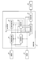
- FIG. 17 is a detailed configuration example of the image processing unit in the second embodiment.
- FIG. 18 is a detailed configuration example of the exclusion target identification unit.
- FIG. 19 is a detailed configuration example of the excluded subject identification unit.
- FIG. 20 shows an example of a captured image when inserting forceps.
- 21 (A) to 21 (C) are explanatory diagrams of exclusion target identification processing in the case where the treatment tool is to be excluded.
- FIG. 22 is a detailed configuration example of the excluded scene identification unit.
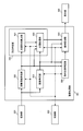
- FIG. 23 is a detailed configuration example of the image processing unit in the third embodiment.
- FIG. 24A is a view showing the relationship between an imaging unit and an object when observing an abnormal part.
- FIG. 24B is an example of the acquired image.
- FIG. 25 is an explanatory diagram of classification processing.
- FIG. 26 is a detailed configuration example of a biological mucous membrane identifying unit in the third embodiment.
- FIG. 27 is a detailed configuration example of the image processing unit in the first modified example of the third embodiment.
- FIG. 28 is a detailed configuration example of the image processing unit in the second modified example of the third embodiment.
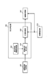
- FIG. 29 is a detailed configuration example of the image processing unit in the fourth embodiment.
- FIG. 30 is a detailed structural example of the uneven
- 31 (A) and 31 (B) are explanatory diagrams of processing performed by the surface shape calculation unit.
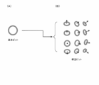
- FIG. 32 (A) shows an example of a basic pit.
- FIG. 32 (B) shows an example of a correction pit.
- FIG. 33 is a detailed configuration example of the surface shape calculation unit.
- FIG. 32 (A) shows an example of a basic pit.
- FIG. 32 (B) shows an example of a correction pit.
- FIG. 33 is a detailed configuration example of the surface shape calculation unit.
- FIG. 34 shows a detailed configuration example of a classification processing unit in the first classification processing method.
- 35 (A) to 35 (F) are explanatory views of a specific example of classification processing.
- FIG. 36 shows a detailed configuration example of a classification processing unit in the second classification processing method.
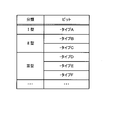
- FIG. 37 shows an example of classification types in the case of using a plurality of classification types.
- FIGS. 38A to 38F show examples of pit patterns.
- Method of this embodiment As a method of emphasizing the unevenness of the subject, there is a method of imaging the subject after the change by causing some change on the subject side.
- the endoscope apparatus for the living body there is a method of staining the living body itself and applying a contrast to the surface mucous membrane by dispersing a pigment such as indigo carmine.
- pigment dispersion is time-consuming and costly, and there is a risk that the inherent pigmentation may impair the original color of the subject, and the visibility of structures other than irregularities may be reduced.
- pigment dispersion to a living body may cause a problem of being highly invasive to the patient.
- the unevenness of the subject is emphasized by image processing.
- the uneven portion itself but also the uneven portion may be classified, and emphasis may be performed according to the classification result.
- the emphasizing process for example, various methods such as reproduction of the pigment dispersion described above and emphasizing of high frequency components can be adopted.
- emphasizing by image processing there is a problem that the unevenness of the subject to be emphasized and the unevenness of the subject not to be emphasized are similarly emphasized.
- the emphasis process is performed on the subject to be emphasized.
- the image is an image of an object (or a scene) to be emphasized, the emphasis process on the object (or the entire image) is excluded or suppressed.
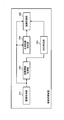
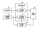
- FIG. 1 shows a first configuration example of an image processing apparatus as a configuration example in the case of performing enhancement processing on a subject to be enhanced.
- the image processing apparatus includes an image acquisition unit 310, a distance information acquisition unit 320, an unevenness specifying unit 350, a biological mucous membrane specifying unit 370, and an emphasis processing unit 340.
- the image acquisition unit 310 acquires a captured image including an image of a subject.
- the distance information acquisition unit 320 acquires distance information based on the distance from the imaging unit to the subject when capturing a captured image.
- the concavo-convex specifying unit 350 specifies the concavo-convex portion of the subject that matches the characteristic identified by the known characteristic information based on the distance information and the known characteristic information that is information representing the known characteristic regarding the structure of the subject. Perform unevenness identification processing.
- the in-vivo mucous membrane identifying unit 370 identifies an area of the in-vivo mucous membrane in the captured image.
- the emphasizing unit 340 emphasizes the identified area of the mucous membrane of the living body based on the information of the uneven portion specified by the uneven part specifying process.
- this configuration example it is possible to specify a living body mucous membrane which is a subject to be emphasized, and to perform an emphasizing process on the specified living body mucous membrane. That is, it is possible to apply emphasis processing to a living mucous membrane and not apply or suppress emphasizing processing to a region other than a living mucous membrane that does not need to be emphasized. This makes it easy for the user to distinguish between the mucous membrane of the living body and the other area, thereby improving the examination accuracy and reducing the user's fatigue.
- the distance information is information in which each position of the captured image is associated with the distance to the subject at each position.
- the distance information is a distance map.
- the distance map for example, when the optical axis direction of the imaging unit 200 in FIG. 3 is the Z axis, the distance (depth / depth) in the Z axis direction to the subject at each point (for example, each pixel) in the XY plane Is a map with the value of that point.
- the distance information may be various information acquired based on the distance from the imaging unit 200 to the subject. For example, in the case of triangulation with a stereo optical system, a distance based on an arbitrary point on a surface connecting two lenses generating parallax may be used as distance information. Alternatively, in the case of using the Time of Flight method, for example, a distance based on each pixel position of the imaging device surface may be acquired as distance information.
- the reference point for distance measurement is set in the imaging unit 200, but the reference point is an arbitrary location other than the imaging unit 200, for example, an arbitrary location in a three-dimensional space including the imaging unit and the subject. It may be set, and information when using such a reference point is also included in the distance information of the present embodiment.
- the distance from the imaging unit 200 to the subject may be, for example, the distance from the imaging unit 200 to the subject in the depth direction.
- the distance in the optical axis direction of the imaging unit 200 may be used.
- the viewpoint is set in a direction perpendicular to the optical axis of the imaging unit 200, the distance observed from the viewpoint (from the imaging unit 200 on the line parallel to the optical axis passing through the Distance)).
- the distance information acquisition unit 320 performs a known coordinate conversion process on the coordinates of each corresponding point in the first coordinate system with the first reference point of the imaging unit 200 as the origin, as a second coordinate in the three-dimensional space.
- the coordinates may be converted into the coordinates of the corresponding point in the second coordinate system with the reference point as the origin, and the distance may be measured based on the converted coordinates.
- the distance from the second reference point in the second coordinate system to each corresponding point is the distance from the first reference point in the first coordinate system to each corresponding point, that is, “the corresponding points from the imaging unit The distance between the two is the same.
- the distance information acquisition unit 320 is virtual at a position where the same magnitude relationship as the magnitude relationship between distance values between pixels on the distance map acquired when the reference point is set in the imaging unit 200 can be maintained.
- distance information based on the distance from the imaging unit 200 to the corresponding point may be acquired. For example, when the actual distances from the imaging unit 200 to the three corresponding points are “3”, “4”, and “5”, for example, the distance information acquiring unit 320 maintains the magnitude relationship of the distance values between the pixels. It is also possible to obtain “1.5”, “2”, “2.5” in which the distances are uniformly halved. As described later in FIG.
- the unevenness information acquisition unit 380 acquires unevenness information using the extraction processing parameter
- the unevenness information acquisition unit 380 extracts as compared with the case where the reference point is set in the imaging unit 200.
- Different parameters will be used as processing parameters. Since it is necessary to use distance information to determine the extraction processing parameter, the method of determining the extraction processing parameter also changes when the way of representing the distance information is changed due to the change of the reference point of the distance measurement. For example, when extracting extraction unevenness information by morphology processing as described later, the size (for example, the diameter of a sphere) of the structural element used for the extraction process is adjusted, and extraction of the unevenness portion is performed using the adjusted structural element Perform the process.
- the known characteristic information is information which can separate the structure useful in the present embodiment and the structure not so among the structures of the object surface.
- information on uneven portions that is useful to emphasize may be used as known characteristic information, in which case a subject that matches the known characteristic information is the target of emphasis processing.
- a structure that is not useful even if emphasized may be used as known characteristic information, in which case an object that does not match the known characteristic information is to be emphasized.
- information on both the useful unevenness and the non-useful structure may be held, and the range of the useful unevenness may be set with high accuracy.
- the known characteristic information is information that can classify the structure of the subject into a particular type or state.
- it is information for classifying a structure of a living body into types such as blood vessels, polyps, cancer, and other lesions, and information such as shape, color, size, etc. characteristic of those structures.
- it may be information that can determine whether a specific structure (for example, a pit pattern present in the large intestine mucosa) is normal or abnormal, etc., and the shape of the normal or abnormal structure. It may be information such as color and size.
- the area of the in-vivo mucous membrane is not limited to the entire in-vivo mucous membrane shown in the captured image, but a part thereof may be specified as the in-vivo mucous membrane. That is, the part which is the implementation object of emphasis processing among the body mucous membranes should just be specified as a field of the body mucous membrane.
- a groove region which is a part of the surface of the living body is specified as a region of the living mucous membrane, and the region is emphasized.
- a portion where a feature (for example, color) other than the unevenness on the surface of the living body meets a predetermined condition is specified as the region of the living mucous membrane.
- FIG. 2 shows a second configuration example of the image processing apparatus as a configuration example in the case of excluding or suppressing enhancement processing on a subject (or a scene) that should not be enhanced.
- the image processing apparatus includes an image acquisition unit 310, a distance information acquisition unit 320, an unevenness information acquisition unit 380, an exclusion target identification unit 330, and an emphasis processing unit 340.
- the image acquisition unit 310 acquires a captured image including an image of a subject.
- the distance information acquisition unit 320 acquires distance information based on the distance from the imaging unit to the subject when capturing a captured image.
- the concavo-convex specifying unit 350 specifies the concavo-convex portion of the subject that matches the characteristic identified by the known characteristic information based on the distance information and the known characteristic information that is information representing the known characteristic regarding the structure of the subject. Perform unevenness identification processing.
- the emphasizing processing unit 340 performs emphasizing processing on the captured image based on the information of the concavo-convex portion specified by the concavo-convex specifying processing.
- the exclusion target specifying unit 330 specifies an exclusion target area in the captured image for which enhancement processing is not performed. At this time, the emphasizing processing unit 340 does not apply or suppresses emphasizing processing on the identified exclusion target area.
- the emphasizing process is applied to the area other than the exclusion target, and as a result, the emphasizing process can be performed on the biological mucous membrane to be emphasized. This makes it easy for the user to distinguish between the mucous membrane of the living body and the other area, thereby improving the examination accuracy and reducing the user's fatigue.
- the exclusion target is a subject or scene that does not need to be emphasized (for example, not a living body) or a subject or a scene that is not useful to emphasize (for example, to enhance the doctor's medical examination by emphasizing).
- a subject such as a residue or a blood clot, a treatment tool, a sunken (blackout) area, a whiteout (highlight) area, or a treatment with, for example, water supply or IT knife.
- mist is generated when the knife cauterizes a living body. If an image in which such mist is captured is enhanced, there is a possibility that the image will be rather difficult to observe.
- the enhancement processing of the area is not applied (or suppressed), and in the case of an image obtained by capturing the scene to be excluded, the entire image Do not apply (or suppress) emphasis processing of
- a local uneven structure eg, polyp, eyebrows, etc.
- a desired size eg, width, height, depth, etc.
- the extraction process is performed excluding the global structure (for example, the surface undulation larger than the scale).
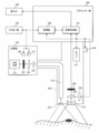
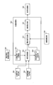
- FIG. 3 shows an example of the configuration of the endoscope apparatus according to the first embodiment.
- the endoscope apparatus includes a light source unit 100, an imaging unit 200, a processor unit 300, a display unit 400, and an external I / F unit 500.
- the light source unit 100 includes a white light source 110, a light source diaphragm 120, a light source diaphragm driving unit 130 for driving the light source diaphragm 120, and a rotational color filter 140 having filters of a plurality of spectral transmittances.
- the light source unit 100 also includes a rotary drive unit 150 for driving the rotary color filter 140, and a condenser lens 160 for condensing light transmitted through the rotary color filter 140 on the incident end face of the light guide fiber 210.
- the light source diaphragm drive unit 130 adjusts the light amount by opening and closing the light source diaphragm 120 based on a control signal from the control unit 302 of the processor unit 300.
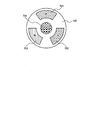
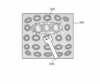
- FIG. 4 shows a detailed configuration example of the rotary color filter 140.
- the rotating color filter 140 is composed of three primary color red (abbreviated as R) filters 701, a green (abbreviated as G) filter 702, a blue (abbreviated as B) filter 703, and a rotating motor 704.
- R red
- G green
- B blue
- the R filter 701 transmits light having a wavelength of 580 nm to 700 nm
- the G filter 702 transmits light having a wavelength of 480 nm to 600 nm
- the B filter 703 transmits light having a wavelength of 400 nm to 500 nm.
- the rotation drive unit 150 rotates the rotation color filter 140 at a predetermined rotation speed in synchronization with the imaging period of the imaging device 260 based on the control signal from the control unit 302. For example, if the rotary color filter 140 is rotated 20 times per second, each color filter will cross incident white light at intervals of 1/60 second. In this case, the imaging device 260 completes the imaging and transfer of the image signal at an interval of 1/60 of a second.
- the imaging device 260 is, for example, a monochrome single-plate imaging device, and is configured of, for example, a CCD, a CMOS image sensor, or the like. That is, in the present embodiment, imaging in a plane-sequential method is performed in which images of respective primary colors (R, G, or B) of three primary colors are captured at an interval of 1/60 second.
- the imaging unit 200 is formed to be elongated and bendable, for example, to allow insertion into a body cavity.
- the imaging unit 200 diffuses the light guided to the tip by the light guide fiber 210 for guiding the light collected by the light source unit 100 to the illumination lens 220 and irradiates the observation target with the light And an illumination lens 220.
- the imaging unit 200 includes an objective lens 230 for condensing reflected light returning from an observation target, a focus lens 240 for adjusting a focal position, and a lens driving unit 250 for moving the position of the focus lens 240.
- an imaging element 260 for detecting the collected reflected light.
- the lens driving unit 250 is, for example, a VCM (Voice Coil Motor), and is connected to the focus lens 240.
- the lens drive unit 250 adjusts the in-focus object position by switching the position of the focus lens 240 at a continuous position.
- the imaging unit 200 is provided with a switch 270 for allowing the user to instruct on / off of the emphasizing process.
- a switch 270 for allowing the user to instruct on / off of the emphasizing process.
- an on / off instruction signal of enhancement processing is output from the switch 270 to the control unit 302.
- the imaging unit 200 also includes a memory 211 in which information of the imaging unit 200 is recorded.
- a scope ID indicating the use of the imaging unit 200
- information of optical characteristics of the imaging unit 200 information of a function of the imaging unit 200, and the like are recorded.
- the scope ID is, for example, an ID corresponding to a scope for the lower digestive tract (large intestine) or a scope for the upper digestive tract (esophagus, stomach).
- the information of the optical characteristic is, for example, information such as the magnification (angle of view) of the optical system.
- the information of the function is information representing the execution state of the function such as water supply provided in the scope.
- the processor unit 300 (control device) performs control of each unit of the endoscope apparatus and image processing.
- the processor unit 300 includes a control unit 302 and an image processing unit 301.
- the control unit 302 is bidirectionally connected to each unit of the endoscope apparatus, and controls each unit. For example, the control unit 302 transfers the control signal to the lens drive unit 250 to change the position of the focus lens 240.
- the image processing unit 301 performs a process of specifying an area of a biological mucous membrane from a captured image, an enhancement process of the specified area of a biological mucous membrane, and the like. Details of the image processing unit 301 will be described later.
- the display unit 400 displays the endoscopic image transferred from the processor unit 300.
- the display unit 400 is an image display device capable of displaying moving images, such as an endoscope monitor, for example.
- the external I / F unit 500 is an interface for performing input from the user to the endoscope apparatus.
- the external I / F unit 500 starts, for example, a power switch for turning on / off the power, a mode switching button for switching the shooting mode and other various modes, and an autofocus operation for automatically focusing on the subject.
- Is configured to include an AF button and the like.
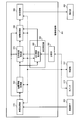
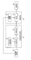
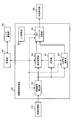
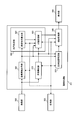
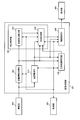
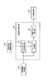
- FIG. 5 shows a configuration example of the image processing unit 301 in the first embodiment.
- the image processing unit 301 includes an image acquisition unit 310, a distance information acquisition unit 320, a biological mucous membrane identification unit 370, an emphasis processing unit 340, a post-processing unit 360, an unevenness identification unit 350, and a storage unit 390.
- the unevenness identification unit 350 includes an unevenness information acquisition unit 380.
- the image acquisition unit 310 is connected to the distance information acquisition unit 320, the biological mucous membrane identification unit 370, and the emphasis processing unit 340.
- the distance information acquisition unit 320 is connected to the in-vivo mucous membrane identification unit 370 and the unevenness information acquisition unit 380.
- the biological mucous membrane identification unit 370 is connected to the emphasis processing unit 340.
- the emphasizing processing unit 340 is connected to the post-processing unit 360.
- the post-processing unit 360 is connected to the display unit 400.
- the unevenness information acquisition unit 380 is connected to the in-vivo mucous membrane identification unit 370 and the emphasis processing unit 340.
- the storage unit 390 is connected to the unevenness information acquisition unit 380.
- the control unit 302 is bidirectionally connected to each unit of the image processing unit 301, and controls each unit. For example, the control unit 302 synchronizes the image acquisition unit 310, the post-processing unit 360, and the light source aperture drive unit 130. Further, the switch 270 (or the external I / F unit 500) transfers an emphasis processing on / off instruction signal to the emphasis processing unit 340.
- the image acquisition unit 310 converts an analog image signal transferred from the imaging device 260 into a digital image signal by A / D conversion processing. Then, OB clamp processing, gain correction processing, and WB correction processing are performed on the digital image signal using the OB clamp value, gain correction value, and WB coefficient value stored in advance in the control unit 302. Further, the synchronization processing is performed on the R image, the G image, and the B image captured by the field sequential method, and a color image having RGB pixel values for each pixel is acquired. The color image is transferred as an endoscopic image (captured image) to the distance information acquisition unit 320, the biological mucous membrane identification unit 370, and the emphasis processing unit 340.
- the A / D conversion process may be performed at a stage before the image processing unit 301 (for example, built in the imaging unit 200).
- the distance information acquisition unit 320 acquires distance information to the subject based on the endoscope image, and transfers the distance information to the biological mucous membrane identification unit 370 and the unevenness information acquisition unit 380.
- the distance information acquisition unit 320 detects the distance to the subject by calculating the blur parameter from the endoscopic image.
- the imaging unit 200 may have an optical system for capturing a stereo image, and the distance information acquisition unit 320 performs stereo matching processing on the stereo image to detect the distance to the subject. Good.
- the imaging unit 200 may have a sensor that detects TOF (Time Of Flight), and the distance information acquisition unit 320 may detect the distance to the subject based on the sensor output. The details of the distance information acquisition unit 320 will be described later.
- TOF Time Of Flight
- the distance information is, for example, a distance map having distance information corresponding to each pixel of the endoscopic image.
- the distance information includes both information representing the rough structure of the subject and information representing the unevenness relatively smaller than the rough structure.
- the information representing the rough structure corresponds to, for example, the rough structure of the luminal structure or mucous membrane originally possessed by the organ, and is, for example, a low frequency component of distance information.
- the information representing the unevenness corresponds to, for example, the unevenness of the mucous membrane surface or the lesion, and is, for example, a high frequency component of the distance information.
- the concavo-convex information acquisition unit 380 extracts the extracted concavo-convex information representing the concavo-convex part on the surface of the living body from the distance information, based on the known characteristic information stored in the storage unit 390. Specifically, the concavo-convex information acquisition unit 380 acquires, as known characteristic information, the size (dimension information such as width, height, depth, etc.) of the concavo-convex portion unique to the living body desired to be extracted, and the desired dimension represented by the known characteristic information. Extract asperities having characteristics. Details of the unevenness information acquisition unit 380 will be described later.
- the biological mucous membrane identification unit 370 identifies an area of a biological mucous membrane (for example, a part of a biological body in which a lesion may be present) to be subjected to enhancement processing in an endoscopic image. As described later, for example, based on an endoscopic image, a region that matches the color feature of the in-vivo mucous membrane is specified as the in-vivo mucous membrane region.
- a region matching the feature of the biological mucous membrane (for example, a recess or a groove) to be emphasized is specified as a region of the biological mucous membrane among the concavity and convexity represented by the extracted concavity and convexity information.
- the in-vivo mucous membrane identification unit 370 determines whether each pixel is in-vivo mucous membrane, and outputs positional information (coordinates) of the pixel determined to be in-vivo mucous membrane to the emphasis processing unit 340.
- a set of pixels determined to be the in-vivo mucous membrane corresponds to the area of the in-vivo mucous membrane.
- the emphasizing processing unit 340 performs emphasizing processing on the identified area of the mucous membrane of the living body, and outputs the endoscopic image to the post-processing unit 360.
- the biological mucous membrane identification unit 370 specifies the region of the biological mucous membrane by color
- the emphasizing unit 340 emphasizes the region of the biological mucous membrane based on the extracted unevenness information.
- the in-vivo mucous membrane identification unit 370 identifies the area of the in-vivo mucous membrane based on the extracted unevenness information
- the emphasizing unit 340 emphasizes the in-vivo mucous membrane area. In any case, the emphasizing process is performed based on the extracted unevenness information.
- the emphasizing process may be, for example, a process of emphasizing a concavo-convex structure (for example, a high frequency component of an image) of a living mucous membrane, or a process of emphasizing a predetermined color component according to the concavo-convex of the living mucous membrane.
- processing for reproducing pigment dispersion may be performed by making predetermined color components darker in concave portions than in convex portions.
- the post-processing unit 360 performs tone conversion on the endoscope image transferred from the enhancement processing unit 340 using tone conversion coefficients, color conversion coefficients, and edge enhancement coefficients stored in advance in the control unit 302. Performs processing, color processing, and edge enhancement processing.
- the post-processing unit 360 transfers the post-processed endoscopic image to the display unit 400.
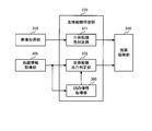
- FIG. 6 shows a detailed configuration example of the biological mucous membrane identification unit 370.
- the biological mucous membrane identification unit 370 includes a biological mucous membrane color judgment unit 371 and a biological mucous membrane unevenness judgment unit 372.
- at least one of the in-vivo mucous membrane color determination unit 371 and the in-vivo mucous membrane unevenness determination unit 372 identifies the region of the in-vivo mucous membrane.
- the endoscopic image is transferred from the image acquisition unit 310 to the in-vivo mucous membrane color determination unit 371.
- the biological mucous membrane color determination unit 371 compares the hue value at each pixel of the endoscopic image with the range of hue values possessed by the biological mucous membrane, and determines whether each pixel corresponds to the biological mucous membrane.
- a pixel whose hue value H satisfies the following expression (1) is determined as a pixel corresponding to a biological mucous membrane (hereinafter referred to as a biological mucous membrane pixel). 10 ° ⁇ H ⁇ 30 ° (1)
- the hue value H is calculated from the RGB pixel values by the following equation (2), and takes a range of 0 ° to 360 °.
- max (R, G, B) is the maximum value among R pixel value, G pixel value, and B pixel value
- min (R, G, B) is R pixel value, G pixel Value, which is the minimum value of B pixel values.
- the emphasizing process can be performed by limiting to a region in which the in-vivo mucous membrane can be determined from the color feature. As a result, it is possible to perform an emphasizing process suitable for medical examination, in order not to emphasize a subject that does not need to be emphasized.
- the distance information is transferred from the distance information acquisition unit 320 to the biological mucous membrane unevenness determination unit 372, and the extracted unevenness information is transferred from the unevenness information acquisition unit 380.
- the biological mucous membrane unevenness judgment unit 372 judges whether each pixel corresponds to a biological mucous membrane based on the distance information and the extracted unevenness information. Specifically, based on the extracted asperity information, a groove on the surface of the living body (for example, a recess with a width of 1000 ⁇ m or less (including its value) and a depth of 100 ⁇ m or less (including its value)) is detected.
- the above equation (4) represents that the pixel at the coordinates (p, q) is a pixel detected as a groove on the surface of the living body.
- D (x, y) is the distance to the subject at the pixel at coordinate (x, y)
- D (p, q) is the distance to the subject at the pixel at coordinate (p, q) It is a distance.
- Tneighbor is a threshold for the distance difference between pixels.
- the distance information acquisition unit 320 acquires a distance map as distance information.
- the distance map means, for example, the distance (depth / depth) in the Z-axis direction to the subject at each point (for example, each pixel) in the XY plane when the optical axis direction of the imaging unit 200 is the Z axis. It is the map which made the value of the point concerned.
- the distance D (x, y) at the coordinate (x, y) of the endoscopic image is the coordinate (x, y) of the distance map. It is the value in).
- the biological mucous membrane on which enhancement processing is to be performed is specified in the endoscopic image, and the specified biological mucous membrane on the subject surface is Emphasize unevenness information.
- the emphasizing process can be performed on the area requiring the emphasizing process, so the ability to distinguish between the area requiring the emphasizing process and the area not requiring the emphasizing process is improved, and the user feels tired in image observation when the emphasizing process is performed. Can be minimized.
- the biological mucous membrane specifying unit 370 specifies a region in which the feature amount based on the pixel value of the captured image satisfies the predetermined condition corresponding to the biological mucous membrane as the region of the biological mucous membrane. More specifically, the in-vivo mucous membrane identification unit 370 uses, as the in-vivo mucous membrane area, a region in which color information (for example, hue value) that is a feature amount satisfies a predetermined condition (for example, a range of hue values) Identify.
- a predetermined condition for example, a range of hue values
- the subject to be emphasized can be identified based on the feature amount of the image. That is, by setting the feature of the mucous membrane of the living body as the condition of the feature amount and detecting the region meeting the predetermined condition, it is possible to specify the subject to be emphasized. For example, by setting a color characteristic of the mucous membrane of the living body as a predetermined condition, it is possible to specify an area matching the color condition as a subject to be emphasized.
- the in-vivo mucous membrane identifying unit 370 identifies an area in which the extracted asperity information matches the asperity characteristic that is the known characteristic information as the in-vivo mucous membrane area. More specifically, the in-vivo mucous membrane identification unit 370 acquires, as known characteristic information, dimension information representing at least one of the width and the depth of the recess (groove) of the subject, and among the irregularities included in the extracted unevenness information, Extract a recess that matches the characteristics specified by the dimension information. Then, the recessed area which is an area on the captured image corresponding to the extracted recessed area and the area near the recessed area are specified as the area of the mucous membrane of the living body.
- the subject to be emphasized can be identified based on the uneven shape of the subject. That is, by setting the feature of the mucous membrane of the living body as the condition of the concavo-convex shape and detecting the region meeting the predetermined condition, the subject to be emphasized can be specified. Further, by specifying the recessed area as the area of the mucous membrane of the living body, the emphasizing process can be performed on the recessed area. As will be described later, in the case of dye dispersion, since the concave portions on the surface of the living body tend to be dyed deeply, it is possible to reproduce the dye dispersion by image processing by emphasizing the concave portions.
- the concavo-convex characteristic is a characteristic of the concavo-convex portion specified by the concavo-convex characteristic information.
- the asperity characteristic information is information for specifying the asperity characteristic of the subject that is desired to be extracted from the distance information. Specifically, it includes at least one of information indicating the characteristics of the unevenness to be non-extracted and the information indicating the characteristics of the unevenness to be extracted among the unevenness included in the distance information.
- the emphasizing process is performed such that the emphasizing process is turned on for the area of the mucous membrane of the living body and the emphasizing process is turned off for the other areas.
- the emphasizing processing unit 340 performs emphasizing processing with an emphasizing amount that changes continuously at the boundary between the region of the mucous membrane of the body and the other region.
- the amount of enhancement is multi-valued (for example, 0% to 100%) by applying a low-pass filter to the amount of enhancement at the boundary between the region of the body mucous membrane and the other region. Make it continuous.
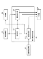
- FIG. 8 shows a detailed configuration example of the unevenness information acquisition unit 380.
- the unevenness information acquisition unit 380 includes a known characteristic information acquisition unit 381, an extraction processing unit 383 and an extraction unevenness information output unit 385.
- an uneven portion having a desired dimension characteristic (in a narrow sense, an uneven portion whose width is in a desired range) is extracted as extracted uneven information. Since the three-dimensional structure of the subject is reflected in the distance information, the distance information is a rough surface corresponding to the eyebrow structure, which is a larger structure than the desired uneven portion, and the wall surface structure of the lumen. Structure is included. That is, it can also be said that the extraction unevenness information acquisition process of the present embodiment is a process of excluding the eyelid structure and the lumen structure from the distance information.
- the extraction unevenness information acquisition process is not limited to this.
- the known characteristic information may not be used in the process of acquiring the extracted unevenness information.
- various modifications can be made as to what kind of information is used as the known characteristic information.
- information on lumen structure may be excluded from distance information, but extraction processing may be performed to leave information on hemorrhoid structure.
- known property information for example, dimension information of a recess
- the known characteristic information acquisition unit 381 acquires known characteristic information from the storage unit 390. Specifically, the size of the unevenness inherent in the living body that is desired to be extracted from the lesion surface (dimension information such as width, height, depth, etc.), and the size of the area specific lumen and fold based on the observation area information ( Dimension information such as width, height, and depth is acquired as known characteristic information.
- the observation site information is information indicating a site to be observed, which is determined based on, for example, scope ID information, and the observation site information may also be included in the known characteristic information.
- the observation site is the esophagus, the stomach, and the duodenum
- the observation site is the information determined to be the large intestine. Since the dimension information of the uneven portion to be extracted and the lumen and ⁇ region specific information of the region are different depending on the region, the known characteristic information acquisition unit 381 obtains the standard information acquired based on the observation region information. The information such as the size of the lumen and the fistula is output to the extraction processing unit 383.
- the observation site information is not limited to the one determined by the scope ID information, but may be determined by another method such as being selected using a switch operable by the user in the external I / F unit 500.
- the extraction processing unit 383 determines an extraction processing parameter based on the known characteristic information, and performs extraction processing of the extracted unevenness information based on the determined extraction processing parameter.
- the extraction processing unit 383 performs low-pass filter processing of a predetermined size of N ⁇ N pixels on the input distance information to extract rough distance information. Then, based on the extracted rough distance information, an extraction processing parameter is determined adaptively. Details of the extraction processing parameters will be described later, for example, the kernel size of the morphology (size of structural element) adapted to the distance information at the plane position orthogonal to the distance information of the distance map or the distance information of the plane position. It is the low pass characteristic of the adapted low pass filter or the high pass characteristic of the high pass filter adapted to the planar position. That is, it is change information for changing an adaptive non-linear and linear low-pass filter or high-pass filter according to distance information.
- the low-pass filter processing here is intended to suppress the reduction in the accuracy of the extraction processing due to frequent or extreme changes of the extraction processing parameters according to the position on the image, and the accuracy reduction is a problem. If not, it is not necessary to perform low pass filter processing.
- the extraction processing unit 383 performs extraction processing based on the determined extraction processing parameter, thereby extracting only the uneven portion of a desired size existing in the subject.
- the extraction concavo-convex information output unit 385 sends the extracted concavo-convex portion to the biological mucous membrane identification unit 370 or the emphasis processing unit 340 as extraction concavo-convex information (concave and convexity image) of the same size as the captured image (image to be enhanced). Output.
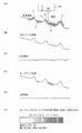
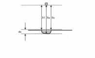
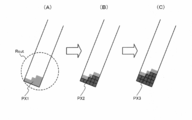
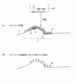
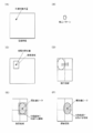
- FIGS. 9A to 9F are the diameters of structural elements (spheres) used for the opening processing of the morphological processing and the closing processing.
- FIG. 9A is a view schematically showing a cross section in the vertical direction of the living body surface of the subject and the imaging unit 200.
- the wrinkles 2, 3 and 4 on the living body surface are, for example, the wrinkles of the stomach wall. Further, it is assumed that the early lesions 10, 20, 30 are formed on the surface of the living body.
- the extraction processing parameter determination processing in the extraction processing unit 383 is the extraction for extracting only the early lesions 10, 20, 30 without extracting the wrinkles 2, 3, 4 from such a living body surface It is to determine processing parameters.
- the diameter of the sphere is smaller than the size of the region-specific lumen and eyebrow based on the observation region information, and the diameter is set larger than the size of the body-specific unevenness to be extracted due to the lesion. More specifically, it is preferable to set the diameter smaller than half of the size of the eyebrows to be equal to or larger than the size of the unevenness inherent in the living body to be extracted due to the lesion.
- FIGS. 9 (A) to 9 (F) An example in which a sphere satisfying the above conditions is used for the opening process and the closing process is depicted in FIGS. 9 (A) to 9 (F).
- FIG. 9 (B) shows the surface of the living body after the closing process.
- extraction processing parameters size of the structural element
- extraction is performed while maintaining the distance change due to the biological wall and the structure such as wrinkles. It can be seen that, among the uneven portions of the target dimension, information in which the concave portion is filled can be obtained.
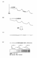
- FIG. 9C By taking the difference between the information obtained by the closing process and the original living body surface (corresponding to FIG. 9A), it is possible to extract only the recess on the living body surface as shown in FIG. 9C.
- FIG. 9D shows the surface of the living body after the opening process, and it is understood that among the uneven portions of the dimension to be extracted, information in which the convex portion is scraped can be obtained. Therefore, by taking the difference between the information obtained by the opening process and the original living body surface, it is possible to extract only the convex portion of the living body surface as shown in FIG. 9 (E).
- control may be performed to increase the diameter of the sphere when the distance information is close and reduce the diameter of the sphere when the distance information is far.
- control is performed such that the diameter of the sphere is changed with respect to average distance information in the case of performing opening processing and closing processing on the distance map. That is, in order to extract a desired uneven portion with respect to the distance map, it is necessary to correct with the optical magnification in order to make the real size of the living body surface coincide with the size of the pixel pitch on the image formed on the imaging device . Therefore, it is preferable that the extraction processing unit 383 acquire the optical magnification and the like of the imaging unit 200 determined based on the scope ID information.
- the size of a structural element which is the extraction process parameter when the process by the structural element is performed on the shape which is a non-extraction object such as a weir (in FIG. In the case of (1), the size of a structural element which does not collapse the shape (the ball moves following the shape) is determined.
- the processing by the structural element is performed on the uneven portion to be extracted as the extracted uneven portion information, the uneven portion is eliminated (if it is slid from above, it does not enter into the depressed portion, or is slid from below) In such a case, the size of the structural element which does not enter the convex portion) may be determined.
- the morphological processing is a widely known method, so detailed description will be omitted.
- the asperity information acquisition unit 380 determines the extraction processing parameter based on the known characteristic information, and extracts the asperity portion of the subject as the extraction asperity information based on the determined extraction process parameter.
- extraction processing for example, separation processing
- a specific method of the extraction process may be considered to be the morphological process described above, a filter process described later, etc., in any case, in order to accurately extract the extracted unevenness information, information of various structures included in the distance information From this, it is necessary to control to exclude other structures (for example, a structure unique to a living body such as wrinkles) while extracting information on a desired uneven portion.
- control is realized by setting extraction processing parameters based on known characteristic information.
- the captured image is an in-vivo image obtained by imaging the inside of a living body
- the known characteristic information acquisition unit 381 indicates region information indicating which part of the living body the subject corresponds to; Concavo-convex characteristic information which is information on a part may be acquired as known characteristic information.
- the asperity information acquisition unit 380 determines an extraction processing parameter based on the part information and the asperity characteristic information.
- the site information on the site of the subject of the in-vivo image is , It becomes possible to acquire as known characteristic information.
- extraction of a concavo-convex structure useful for detection of an early lesion and the like as extraction concavities and convexity information is assumed.
- the characteristics (for example, dimension information) of the uneven portion may differ depending on the part.
- the structure unique to the living body to be excluded such as wrinkles naturally varies depending on the site. Therefore, if a living body is targeted, it is necessary to perform appropriate processing according to the site, and in the present embodiment, the process is performed based on the site information.
- the unevenness information acquisition unit 380 determines the size of the structural element used for the opening process and the closing process as the extraction process parameter based on the known property information, and uses the structural element of the determined size.
- the opening process and closing process described above are performed to extract the uneven portion of the subject as the extracted uneven information.
- the extraction process parameter at that time is the size of the structural element used in the opening process and the closing process. Since a sphere is assumed as a structural element in FIG. 9A, the extraction processing parameter is a parameter that represents the diameter of the sphere and the like.
- the extraction process of the present embodiment is not limited to the morphological process, and may be performed by a filter process.
- the unevenness inherent in the living body desired to be extracted due to the lesion can be smoothed, and the characteristics of the low pass filter in which the structure of the lumen and eyebrow specific to the observation site is retained are determined. Since the characteristics of the uneven portion to be extracted, the wrinkles to be excluded, and the lumen structure are known from the known characteristic information, their spatial frequency characteristics become known, and the characteristics of the low pass filter can be determined.
- the low-pass filter may be a well-known Gaussian filter or bilateral filter, the characteristics of which are controlled by ⁇ , and a ⁇ map corresponding to the pixels of the distance map may be created (in the case of the bilateral filter, ⁇ of the luminance difference
- the ⁇ map may be created by using either one or both of the distances ⁇ ).
- the Gaussian filter can be expressed by the following equation (5)
- the bilateral filter can be expressed by the following equation (6).
- a thinned ⁇ map may be created, and a desired low-pass filter may be applied to the distance map by the ⁇ map.
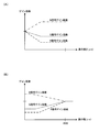
- the ⁇ which determines the characteristics of the low-pass filter is, for example, larger than a predetermined multiple ⁇ (> 1) of the interpixel distance D1 of the distance map corresponding to the size of the unevenness unique to the living body to be extracted
- a value smaller than a predetermined multiple ⁇ ( ⁇ 1) of the inter-pixel distance D2 of the distance map corresponding to the size is set.
- ⁇ ( ⁇ * D1 + ⁇ * D2) / 2 * R ⁇ may be used.
- the filter characteristic is controlled not by ⁇ but by the cutoff frequency fc.
- R ⁇ is a function of the local average distance, and the output value increases as the local average distance decreases, and decreases as the local average distance increases.
- Rf is a function in which the output value decreases as the local average distance decreases and increases as the local average distance increases.
- the recess image can be output by subtracting the low pass processing result from the distance map not subjected to the low pass processing and extracting only a region that is negative. Further, the convex image can be output by subtracting the low-pass processing result from the distance map not subjected to the low-pass processing and extracting only a region that is positive.
- FIGS. 10 (A) to 10 (D) show explanatory views of a process of extracting a desired uneven portion derived from a lesion by a low pass filter.
- filter processing using a low pass filter on the distance map of FIG. 10A, as shown in FIG. 10B, while maintaining the distance change due to the living body wall surface and the structure such as wrinkles, It can be seen that information can be obtained from which the uneven portion of the dimension to be extracted has been removed.
- the low pass filter processing results in the reference phase (FIG. 10 (B)) for extracting the desired uneven portion even without performing the opening processing and the closing processing as described above, the distance map (FIG. 10 (A) By the subtraction process with), the uneven portion can be extracted as shown in FIG.
- FIG. 10 (D) An example is shown in FIG. 10 (D).
- high pass filter processing may be performed instead of low pass filter processing, in which case a high pass filter which holds the unevenness inherent in the living body to be extracted due to the lesion and cuts the structure of the lumen and eyebrow specific to the observation site Determine the characteristics.
- the filter characteristic is controlled at the cutoff frequency fhc.
- the cutoff frequency fhc may be specified to pass the frequency F1 of the D1 cycle and to cut the frequency F2 of the D2 cycle.
- Rf is a function in which the output value decreases as the local average distance decreases, and increases as the local average distance increases.
- the high-pass filter processing it is possible to extract an uneven portion to be extracted directly from the lesion. Specifically, as shown in FIG. 10C, the extracted asperity information is directly acquired without taking the difference.
- the concavo-convex information acquisition unit 380 determines the frequency characteristic of the filter used for the filtering process on the distance information as the extraction process parameter based on the known characteristic information, and determines the determined frequency characteristic.
- a filtering process using a filter is performed to extract the uneven portion of the subject as extracted uneven information.
- the extraction processing parameter at that time is the characteristic (spatial frequency characteristic in a narrow sense) of the filter used in the filter processing.
- the value of ⁇ and the cut-off frequency may be determined based on the frequency corresponding to the exclusion target such as wrinkles and the frequency corresponding to the uneven portion.
- Body mucous membrane unevenness judgment processing emphasizing processing
- the body mucous membrane unevenness judgment unit 372 extracts a recess on the surface of the living body (hereinafter referred to as a groove) and its vicinity as a biological mucous membrane, and the emphasizing processor 340 emphasizes the area of the biological mucous membrane
- the process to be performed will be described in detail.
- an image simulating an image in which indigo carmine is dispersed to improve the contrast of a minute uneven portion on the surface of a living body is created.
- the pixel values of the groove area and the neighboring area are multiplied by a gain that increases bluish.
- the extracted asperity information transferred from the asperity information acquisition unit 380 is in one-to-one correspondence with the endoscopic image input from the image acquisition unit 310 for each pixel.
- FIG. 11 shows a detailed configuration example of the biological mucous membrane unevenness judgment unit 372.
- the biological mucous membrane unevenness determination unit 372 includes a dimension information acquisition unit 601, a recess extraction unit 602, and a vicinity extraction unit 604.
- the dimension information acquisition unit 601 acquires known characteristic information (here, particularly, dimension information) from the storage unit 390 or the like.
- the concave portion extraction unit 602 extracts the concave portion to be emphasized among the concave and convex portions included in the extracted concave and convex information based on the known characteristic information.
- the vicinity extraction unit 604 extracts the surface of the living body within (a vicinity of) a predetermined distance from the extracted recess.
- the groove of the biological body surface is detected from the extracted unevenness information based on the known characteristic information.
- the known characteristic information refers to the width and depth of the groove on the surface of the living body.
- the width of a minute groove on the surface of a living body is several thousand ⁇ m or less (including its value), and the depth is several hundred ⁇ m or less (including its value).
- the width and the depth of the groove on the surface of the living body are calculated from the extracted unevenness information.
- FIG. 12 shows one-dimensional extracted asperity information.
- the distance from the imaging element 260 to the surface of the living body is assumed to be a positive value in the depth direction, with the position of the imaging element 260 (imaging surface) being zero.
- FIG. 13 shows a method of calculating the width of the groove.
- the end of a point separated by a threshold value x1 or more (including that value) from the imaging plane which is farther than the reference plane is detected (Points A and B in FIG. 13) ).
- the distance x1 is a reference plane.
- the number N of pixels corresponding to the inside of the detected point is calculated.
- the average value of the distances x1 to xN from the image pickup element is calculated with respect to the internal point, and is defined as xave.
- the equation for calculating the width w of the groove is shown in the following equation (7).
- p is the width per pixel of the imaging device 260
- K is the optical magnification corresponding to the distance xave from the imaging device on a one-to-one basis.
- w N x p x K (7)
- FIG. 14 shows a method of calculating the depth of the groove.
- the formula for calculating the depth d of the groove is shown in the following formula (8).
- the maximum value of x1 to xN is xM
- the smaller one of x1 and xN is xmin.
- d xM-xmin1 (8)
- the user may set an arbitrary value via the external I / F unit 500 for the reference plane (the plane of the distance x1 from the imaging device). If the calculated groove width and depth match the known characteristic information, the pixel position of the corresponding endoscopic image is determined to be a pixel of the groove area. Here, it is determined whether the width of the groove is equal to or less than 3000 ⁇ m (including its value) and the depth of the groove is equal to or less than 500 ⁇ m (including its value). It is determined that the pixel
- the width and depth of the groove serving as the threshold may be set by the user via the external I / F unit 500.
- the proximity extraction unit 604 detects a pixel on the surface of the living body whose distance in the depth direction is within a predetermined distance from the groove area as a proximity pixel.
- the pixels in the groove area and the pixels in the vicinity area are output to the emphasis processing unit 340 as pixels of the biological mucous membrane.
- the emphasis processing unit 340 includes an emphasis amount setting unit 341 and a correction unit 342.
- the emphasizing processing unit 340 multiplies the pixel value of the biological mucous membrane pixel by the gain coefficient. Specifically, the gain coefficient of one or more (including its value) is multiplied to increase the B signal of the pixel of interest, and the gain coefficient of one or less (including its value) is reduced to decrease the R and G signals. Do. As a result, the grooves (recesses) on the surface of the living body can be bluish to obtain an image as if indigo carmine has been dispersed.
- the correction unit 342 performs a correction process that enhances the visibility of the emphasis target. Details will be described later. At this time, the emphasis amount may be set by the emphasis amount setting unit 341 and correction processing may be performed according to the set emphasis amount.
- an on / off instruction signal of enhancement processing is input from the switch 270 and the external I / F unit 500 via the control unit 302.
- the enhancement processing unit 340 transfers the endoscopic image input from the image acquisition unit 310 to the post-processing unit 360 without performing the enhancement processing.
- emphasis processing is performed.
- the enhancement process may be uniformly performed on the biological mucous membrane pixel. Specifically, it is conceivable to perform enhancement processing using the same gain coefficient for all living body mucous membrane pixels.
- the method of emphasizing processing may be changed among the biological mucous membrane pixels that are targets of the emphasizing processing.
- the gain coefficient may be changed according to the width and depth of the groove, and the enhancement processing using the gain coefficient may be performed. Specifically, the gain coefficient is multiplied so that the bluishness becomes thinner as the depth of the groove becomes shallower. By doing this, it is possible to obtain an image close to that obtained by actual dye dispersion.
- An example of setting of the gain coefficient in this case is shown in FIG.
- the fine structure is useful for lesion detection etc.
- the more the amount of emphasis may be, the finer the groove width is, that is, the setting example of the gain coefficient in this case. Is shown in FIG.
- the color to be colored may be changed according to the depth of the groove.
- the continuity of the grooves can be visually recognized as compared with the emphasizing processing in which the same color tone is applied to all the grooves regardless of their depths, and therefore, a more accurate range diagnosis can be performed.
- the gain is increased to raise the B signal and to lower the R and G signals as emphasis processing, but the gain is not limited to this, and the gain is multiplied to increase the B signal and decrease the R signal. There is no need to multiply. As a result, since the signal values of the B and G signals remain even in the concave portion where the bluishness is increased, the structure in the concave portion is displayed in cyan.
- the target of the enhancement processing is not limited to the living body mucous membrane pixels, and the entire image may be processed.
- processing is performed to increase the visibility, such as increasing the gain coefficient, for the region specified as a biological mucous membrane, and the gain coefficient is decreased to 1 for other regions (same as the original color Or conversion to a specific color (for example, to enhance the visibility of the target to be emphasized so as to be complementary to the target color to be emphasized).
- the enhancement processing of the present embodiment is not limited to the generation of a pseudo image similar to that in the case of using indigo carmine, and can be realized by various types of processing for improving the visibility of an object to be noted.
- FIG. 16 shows a detailed configuration example of the distance information acquisition unit 320.
- the distance information acquisition unit 320 includes a luminance signal calculation unit 323, a difference calculation unit 324, a second derivative calculation unit 325, a blur parameter calculation unit 326, a storage unit 327, and a LUT storage unit 328.
- the calculated luminance signal Y is transferred to the difference calculation unit 324, the second derivative calculation unit 325, and the storage unit 327.
- the difference calculation unit 324 calculates the difference of the luminance signal Y from a plurality of images required for blur parameter calculation.
- the second derivative calculation unit 325 calculates a second derivative of the luminance signal Y in the image, and calculates an average value of second derivatives obtained from a plurality of luminance signals Y different in blur.
- the blur parameter calculation unit 326 calculates a blur parameter by dividing the average value of the second derivative calculated by the second derivative calculator 325 from the difference of the luminance signal Y of the image calculated by the difference calculator 324.
- the storage unit 327 stores the luminance signal Y and the result of the second derivative of the first captured image.
- the distance information acquisition unit 320 can arrange the focus lens at different positions via the control unit 302, and acquire a plurality of luminance signals Y at different times.
- the LUT storage unit 328 stores the relationship between the blur parameter and the subject distance in the form of a look-up table (LUT).
- the control unit 302 is bidirectionally connected to the luminance signal calculation unit 323, the difference calculation unit 324, the second derivative calculation unit 325, and the blur parameter calculation unit 326, and controls them.
- the control unit 302 uses the known contrast detection method, phase difference detection method, or the like based on the photographing mode preset by the external I / F unit 500 to obtain the optimum focus lens position. calculate.
- the lens drive unit 250 drives the focus lens 240 to the calculated focus lens position.
- the first image of the subject is acquired by the imaging device 260 at the driven focus lens position.
- the acquired image is stored in the storage unit 327 via the image acquisition unit 310 and the luminance signal calculation unit 323.
- the lens driving unit 250 drives the focus lens 240 to a second focus lens position different from the focus lens position at which the first image was obtained, and the image sensor 260 obtains a second image of the subject. Do.
- the second image thus acquired is output to the distance information acquisition unit 320 via the image acquisition unit 310.
- the difference calculation unit 324 reads the luminance signal Y of the first image from the storage unit 327, and outputs the luminance signal Y of the first image and the luminance signal calculation unit 323. The difference with the luminance signal Y in the first image is calculated.
- the second derivative calculation unit 325 calculates the second derivative of the luminance signal Y in the second image output from the luminance signal calculation unit 323. Thereafter, the luminance signal Y in the first image is read from the storage unit 327, and the second derivative thereof is calculated. Then, the average value of the calculated second derivative of the first and second images is calculated.
- the blur parameter calculation unit 326 calculates a blur parameter by dividing the average value of the second derivative calculated by the second derivative calculation unit 325 from the difference calculated by the difference calculation unit 324.
- the blur parameter has a linear relationship with the reciprocal of the subject distance. Furthermore, the relationship between the subject distance and the focus lens position is one-to-one correspondence. Therefore, the relationship between the blur parameter and the focus lens position is also in a one-to-one correspondence relationship.
- the relationship between the blur parameter and the focus lens position is stored in the LUT storage unit 328 as a table. Distance information corresponding to the value of the subject distance is represented by the position of the focus lens. Therefore, the blur parameter calculation unit 326 uses the blur parameter and the table information stored in the LUT storage unit 328 to obtain the subject distance with respect to the optical system from the blur parameter by linear interpolation. Thereby, the blur parameter calculation unit 326 calculates the value of the subject distance corresponding to the blur parameter. The calculated subject distance is output to the unevenness information acquisition unit 380 as distance information.
- the imaging unit 200 has an optical system for capturing a left image and a right image (parallax image). Then, the distance information acquisition unit 320 calculates parallax information by performing block matching on the epipolar line with the processing target pixel and its surrounding area (block of a predetermined size) using the left image as a reference image and the parallax information Convert information to distance information. This conversion includes correction processing of the optical magnification of the imaging unit 200. The converted distance information is output to the unevenness information acquisition unit 380 as a distance map consisting of pixels of the same size as the stereo image in a narrow sense.
- the distance information may be obtained by the Time of Flight method or the like using infrared light or the like.
- Time of Flight modification implementation of using not blue light but infrared light is possible.
- Second embodiment 3.1. Image Processing Unit A second embodiment will be described. Similar to the first embodiment, the uneven portion is identified by the extracted uneven information, but unlike the identification of the biological mucous membrane in the first embodiment, an exclusion target for which enhancement processing is not performed (or suppressed) is specified.
- FIG. 17 shows a configuration example of the image processing unit 301 in the second embodiment.
- the image processing unit 301 includes an image acquisition unit 310, a distance information acquisition unit 320, an exclusion target identification unit 330, an emphasis processing unit 340, a post-processing unit 360, an unevenness information acquisition unit 380, and a storage unit 390. including.
- the same components as the components described in the first embodiment will be assigned the same reference numerals and descriptions thereof will be omitted as appropriate.
- the image processing unit 301 is connected to the distance information acquisition unit 320, the exclusion target identification unit 330, and the emphasis processing unit 340.
- the distance information acquisition unit 320 is connected to the exclusion target identification unit 330 and the unevenness information acquisition unit 380.
- the exclusion target identification unit 330 is connected to the emphasis processing unit 340.
- the control unit 302 is bidirectionally connected to each unit of the image processing unit 301, and controls each unit.
- the exclusion target specifying unit 330 specifies an exclusion target for which enhancement processing is not performed (or suppressed) in an endoscopic image based on the endoscopic image from the image acquisition unit 310 and the distance information from the distance information acquisition unit 320. Do. Details of the exclusion target identification unit 330 will be described later.
- the emphasizing processing unit 340 performs emphasizing processing on the endoscopic image based on the extracted concavity and convexity information from the concavity and convexity information acquiring unit 380, and transfers the endoscopic image after the emphasizing processing to the post-processing unit 360.
- the exclusion targets identified by the exclusion target identification unit 330 are excluded from the targets of the emphasizing process (or the emphasizing process is suppressed).
- the emphasis processing may be performed by continuously changing the amount of emphasis at the boundary between the exclusion target area and the other area.
- the emphasizing process for example, the emphasizing process simulating the dye dispersion described in the first embodiment is performed.
- the emphasis processing unit 340 includes the dimension information acquisition unit 601 and the recess extraction unit 602 in FIG. 11, extracts the groove area on the surface of the living body, and emphasizes the B component on the groove area.
- this embodiment is not limited to this, For example, various emphasis processes, such as a structure emphasis process, are employable.
- FIG. 18 shows a detailed configuration example of the exclusion target identification unit 330.
- the exclusion target identification unit 330 includes an exclusion subject identification unit 331, a control information reception unit 332, an exclusion scene identification unit 333, and a determination unit 334.
- the excluded subject identification unit 331 is connected to the determination unit 334.
- the control information accepting unit 332 is connected to the excluded scene identifying unit 333.
- the excluded scene identification unit 333 is connected to the determination unit 334.
- the determination unit 334 is connected to the emphasis processing unit 340.
- the excluded subject specifying unit 331 determines whether or not each pixel of the endoscopic image corresponds to an exclusion target based on the endoscopic image from the image acquiring unit 310 and the distance information from the distance information acquiring unit 320. .
- a set of pixels determined to be excluded (hereinafter, referred to as excluded pixels) is specified as an excluded subject in the endoscopic image.
- the excluded subject is a part of the exclusion target, and the exclusion target includes the excluded scene described later.
- the control information accepting unit 332 extracts control information for controlling the endoscope function related to the exclusion target from the control signals output from the control unit 302, and the extracted control information is excluded scene identification unit Transfer to 333.
- the control information is control information related to the operating state of the endoscope function in which an excluded scene described later may occur. For example, it is control information on on / off of a water supply function provided in the endoscope.
- the excluded scene identification unit 333 identifies an endoscopic image not to be enhanced (or suppressed) based on the endoscopic image from the image acquisition unit 310 and the control information from the control information reception unit 332. With respect to the identified endoscopic image, the enhancement processing is not performed (or suppressed) on the entire image.
- the determination unit 334 specifies the exclusion target in the endoscopic image based on the identification result of the excluded subject identification unit 331 and the identification result of the excluded scene identification unit 333. Specifically, when the endoscopic image is identified as an excluded scene, the entire endoscopic image is identified as an exclusion target. In addition, when the endoscopic image is not identified as an excluded scene, a set of exclusion target pixels is specified as an exclusion target. The determination unit 334 transfers the identified exclusion target to the emphasis processing unit 340.
- FIG. 19 shows a detailed configuration example of the excluded object identification unit 331.
- the excluded subject identification unit 331 includes a color determination unit 611, a brightness determination unit 612, and a distance determination unit 613.
- the image acquisition unit 310 transfers the endoscopic image to the color determination unit 611 and the brightness determination unit 612.
- the distance information acquisition unit 320 transfers the distance information to the distance determination unit 613.
- the color determination unit 611, the brightness determination unit 612, and the distance determination unit 613 are connected to the determination unit 334.
- the control unit 302 is bi-directionally connected to each unit of the excluded subject specifying unit 331, and controls each unit.
- the color determination unit 611 determines whether or not to be an exclusion target pixel based on the color in each pixel of the endoscopic image. Specifically, the color determination unit 611 compares the hue at each pixel of the endoscope image with the predetermined hue corresponding to the excluded subject to determine the exclusion target pixel.
- the excluded subject is, for example, a residue in an endoscopic image. The residue appears generally yellow in endoscopic images.
- the hue H of a pixel satisfies the following expression (10)
- the pixel is determined as an exclusion target pixel because it is a residue. 30 ° ⁇ H ⁇ 50 ° (10)
- the excluded subject is not limited to the residue.
- it may be a subject other than a biological mucous membrane that exhibits a characteristic color in an endoscopic image, such as a metallic color of a treatment tool.
- the excluded subject is determined only by the hue, but it may be determined by further adding saturation.
- the determination target pixel is close to an achromatic color, the hue changes largely even with a slight change in pixel value due to the influence of noise, and it may be difficult to stably determine. In such a case, the excluded subject can be determined more stably by making the determination further taking into consideration the saturation.
- the brightness determination unit 612 determines whether or not to be an exclusion target pixel based on the brightness of each pixel of the endoscopic image. Specifically, the brightness determination unit 612 compares the brightness at each pixel of the endoscope image with the predetermined brightness corresponding to the excluded subject to determine the exclusion target pixel.
- the exclusion target pixel is, for example, a blackout area or a whiteout area.
- the sunk region is a region where improvement in detection accuracy of a lesion can not be expected due to lack of brightness even if enhancement processing is performed on an endoscopic image.
- the overexposed area is an area in the endoscopic image in which a pixel value is saturated and a body mucous membrane to be emphasized is not imaged.
- the brightness determination unit 612 determines that the region satisfying the following equation (11) is a dark region, and determines the region satisfying the following equation (12) as a whiteout region. Y ⁇ T low (11) Y> T high (12)
- Y is a luminance value calculated by the above equation (9).
- T low is a predetermined threshold value for determining the darkened area
- T high is a predetermined threshold value for determining the whiteout area.
- the brightness is not limited to the brightness, and the G pixel value may be adopted as the brightness, or the maximum value among the R pixel value, the G pixel value and the B pixel value may be adopted as the brightness. It is also good.
- the region that does not contribute to the improvement of the detection accuracy of the lesion can be excluded from the target for the enhancement processing.
- the distance determination unit 613 determines whether or not each pixel is an exclusion target pixel constituting an exclusion subject based on the distance information in each pixel of the endoscope image.
- the excluded subject is, for example, a treatment tool.
- the treatment tool exists in a roughly fixed range (treatment tool presence region R tool ) in the endoscopic image EP. Therefore, the distance information in the forceps opening vicinity region Rout on the tip end side of the imaging unit 200 is also known from the design information of the endoscope. Therefore, it is determined in the following procedure whether or not each pixel is an exclusion target pixel that constitutes a treatment tool.
- the distance determination unit 613 determines whether a treatment tool is inserted into the forceps port. Specifically, as shown in FIG. 21A, in the forceps opening vicinity region Rout, the determination is made based on the number of pixels PX1 whose distance satisfies the following expressions (13) and (14). When the number of pixels is equal to or more than a predetermined threshold value, it is determined that the treatment tool is inserted. If it is determined that the treatment tool is inserted, the pixel PX1 is set as the exclusion target pixel. D (x, y) ⁇ T dist (13)
- D (x, y) is the distance (value of the distance map) at the pixel of the coordinates (x, y).
- T dist is a distance threshold in the forceps opening vicinity region Rout, and is set based on the design information of the endoscope.
- the above equation (14) represents that the pixel at the coordinates (x, y) is a pixel present in the forceps opening neighborhood region Rout in the endoscopic image.
- the distance determination unit 613 newly determines a pixel PX2 adjacent to the exclusion target pixel and satisfying the following equations (15) and (16) as the exclusion target pixel.
- D remove (p, q) is the distance (value of the distance map) at the exclusion target pixel adjacent to the pixel at the coordinate (x, y), and (p, q) is the coordinate of the pixel .
- the above equation (16) represents that the pixel at the coordinate (x, y) is a pixel in the treatment tool existing region R tool in the endoscopic image.
- Tneighbor is a threshold value for the difference between the distance at the pixel in the treatment tool existing region R tool and the distance at the exclusion target pixel.
- the distance determination unit 613 repeatedly executes the above determination as shown in FIG. 21 (C).
- the pixel PX3 satisfying the above equations (15) and (16) does not exist any more, or when the number of exclusion target pixels becomes equal to or more than a predetermined number, the repetition of the determination is ended.
- the termination condition is not limited to the above, and the repetition may be terminated when it is determined that the exclusion determination pixel is different from the shape of the treatment instrument, for example, by a known technique such as template matching.
- each component of the excluded object identification unit 331 determines the exclusion target pixel based on different determination criteria (color, brightness, distance), but the present embodiment is not limited to this, and excluded object identification The unit 331 may determine the exclusion target pixel by combining the determination criteria.
- determination criteria color, brightness, distance
- excluded object identification The unit 331 may determine the exclusion target pixel by combining the determination criteria. For example, the case where blood clots at the time of bleeding are specified as excluded subjects will be described. First, in an endoscopic image, blood clots exhibit the color of blood itself. Also, the surface of the blood clot is roughly flat. Therefore, by determining the blood color by the color determination unit 611 and the flatness of the surface of the blood clot by the distance determination unit 613, the blood clot can be identified as an excluded subject.
- the flatness of the surface of the blood clot is determined, for example, by locally summing up the absolute values of the extracted unevenness information. If the local sum of the absolute values of the extracted asper
- the treatment tool can be excluded from the target of the emphasizing process.
- the exclusion target specifying unit 330 specifies, as the exclusion target area, a region where the feature amount based on the pixel value of the captured image satisfies the predetermined condition corresponding to the exclusion target. More specifically, the exclusion target specifying unit 330 determines that color information (for example, hue value) that is a feature amount is a predetermined condition (for example, a color range corresponding to a residue or a color range corresponding to a treatment tool) The area that satisfies) is specified as the area to be excluded.
- color information for example, hue value
- a predetermined condition for example, a color range corresponding to a residue or a color range corresponding to a treatment tool
- the exclusion target specifying unit 330 sets the brightness information (for example, the brightness value) that is the feature amount to a predetermined condition related to the brightness of the exclusion target (for example, the brightness range corresponding to An area satisfying the brightness range corresponding to the area is specified as the exclusion target area.
- the brightness information for example, the brightness value
- a predetermined condition related to the brightness of the exclusion target for example, the brightness range corresponding to An area satisfying the brightness range corresponding to the area is specified as the exclusion target area.
- the color information is not limited to the hue value, and for example, index values representing various colors such as saturation can be adopted.
- the brightness information is not limited to the brightness value, and for example, an index value representing various brightness such as a G pixel value can be adopted.
- the exclusion target specifying unit 330 specifies an area in which the distance information matches the predetermined condition on the distance to be excluded as an area to be excluded. More specifically, the exclusion target specifying unit 330 specifies an area in which the distance to the subject represented by the distance information changes continuously (for example, the area of the forceps shown in the captured image) as the area to be excluded.
- objects to be emphasized can be identified based on the distance. That is, by setting the feature to be excluded as the condition of the distance and detecting the region meeting the predetermined condition, it is possible to specify the subject that should not be emphasized.
- the excluded subject specified by the distance information is not limited to the forceps, and may be any treatment tool that may appear in the captured image.
- FIG. 22 shows a detailed configuration example of the exclusion scene identification unit 333.
- the excluded scene identification unit 333 includes an image analysis unit 621 and a control information determination unit 622. In the present embodiment, when any one of the image analysis unit 621 and the control information determination unit 622 determines that the scene is an excluded scene, the excluded scene identification unit 333 identifies an excluded scene.
- the image acquisition unit 310 transfers the endoscopic image to the image analysis unit 621.
- Control information accepting unit 332 transfers the extracted control information to control information determining unit 622.
- the image analysis unit 621 is connected to the determination unit 334.
- the control information determination unit 622 is connected to the determination unit 334.
- the image analysis unit 621 analyzes the endoscopic image, and determines whether the endoscopic image is an image obtained by capturing an excluded scene.
- the excluded scene is, for example, a water supply scene. During water supply, almost the entire surface of the endoscopic image is covered with flowing water, and there is no subject useful for lesion detection, and there is no need for enhancement processing.
- the image analysis unit 621 calculates an image feature amount from the endoscopic image, compares it with the image feature amount stored in advance in the control unit 302, and determines the water supply scene if the similarity is equal to or more than a predetermined value.
- the image feature quantity stored in advance is a feature quantity calculated from an endoscopic image at the time of water supply, and is, for example, a Haar-like feature quantity.
- the Haar-like feature is described, for example, in Non-Patent Document 1.
- the image feature amount is not limited to the Haar-like feature amount, and another known image feature amount may be used.
- the excluded scene is not limited to the water supply scene, and it may be a scene where a subject useful for lesion detection can not be seen in the endoscopic image, for example, when mist (smoke generated at the time of biological cauterization) is generated.
- mist smoke generated at the time of biological cauterization
- the control information determination unit 622 determines the excluded scene based on the control information from the control information reception unit 332. For example, when control information in which the water supply function is on is input, it is determined that the scene is an excluded scene. Control information for determining an excluded scene is not limited to the ON state of the water supply function. For example, when the function of the IT knife that generates mist is turned on, it may be control information of a function in which a subject useful for lesion detection can not be seen in an endoscopic image.
- the excluded scene identification unit 333 identifies an excluded scene if any one of the image analysis unit 621 and the control information determination unit 622 determines that it is an excluded scene, but the present embodiment is not limited to this. And the determination results of both may be combined to specify an excluded scene. For example, even if there is a possibility of mist generation because the IT knife is turned on, if the IT knife is not in contact with the living body or if the generation of smoke is very small, the subject to be emphasized is displayed. Is desirable. However, since the control information determination unit 622 determines that the scene is an excluded scene when the IT knife is turned on, the emphasizing process is not performed.
- Unnecessary emphasizing processing can be suppressed by determining the excluded scene based on the operation of the function in which the excluded scene may occur.
- the exclusion target for which enhancement processing is not performed is specified in the endoscopic image based on the endoscopic image and the distance information, and the unevenness information of the object surface based on the distance information other than the exclusion target. Emphasize.
- the user's sense of fatigue in image observation can be reduced as compared to the case where emphasis processing is performed.
- the exclusion target identification unit 330 includes the control information reception unit 332 that receives control information of the endoscope apparatus, and the exclusion target identification unit 330 receives the control information received by the control information reception unit 332.
- the captured image is specified as an exclusion target area.
- an image of a scene not to be emphasized can be identified based on the control information of the endoscope apparatus. That is, by setting control information that causes a scene to be excluded as a condition and detecting control information that matches the predetermined condition, it is possible to specify an image of a scene that should not be emphasized. This makes it possible to turn off the enhancement processing when the subject to be observed does not appear in the first place, resulting in enhancement processing only when necessary, thus providing the user with an image suitable for medical examination. it can.
- a process of specifying the uneven portion of the subject a process of classifying the uneven portion into a specific type or state is performed.
- the scale and size of the uneven portion to be classified may be different from or similar to those of the first and second embodiments.
- mucus and polyps of mucous membrane are extracted.
- smaller pit patterns present on mucous surface such as mucus and polyp are classified.
- FIG. 23 shows a configuration example of the image processing unit 301 in the third embodiment.
- the image processing unit 301 includes a distance information acquisition unit 320, an emphasis processing unit 340, an unevenness specifying unit 350, a biological mucous membrane specifying unit 370, and an image configuration unit 810.
- the unevenness identifying unit 350 includes a surface shape calculating unit 820 (three-dimensional shape calculating unit) and a classification processing unit 830.
- the endoscope apparatus can be configured as shown in FIG.
- the same components as those in the first and second embodiments are denoted by the same reference numerals, and the description thereof will be appropriately omitted.
- the image configuration unit 810 is connected to the classification processing unit 830, the biological mucous membrane identification unit 370, and the enhancement processing unit 340.
- the distance information acquisition unit 320 is connected to the surface shape calculation unit 820, the classification processing unit 830, and the biological mucous membrane identification unit 370.
- the surface shape calculation unit 820 is connected to the classification processing unit 830.
- the classification processing unit 830 is connected to the emphasis processing unit 340.
- the biological mucous membrane identification unit 370 is connected to the emphasis processing unit 340.
- the emphasis processing unit 340 is connected to the display unit 400.
- a control unit 302 is bi-directionally connected to each unit of the image processing unit 301 and controls them. The control unit 302 also outputs the optical magnification recorded in the memory 211 of the imaging unit 200 to the image processing unit 301.
- the image configuration unit 810 acquires a captured image output from the imaging unit 200, and performs image processing for converting the captured image into an image that can be output to the display unit 400.
- the imaging unit 200 may have an A / D conversion unit (not shown), and the image configuration unit 810 performs OB processing, gain processing, ⁇ processing, etc. on the digital image from the A / D conversion unit.
- the image configuration unit 810 outputs the processed image to the classification processing unit 830, the biological mucous membrane identification unit 370, and the emphasis processing unit 340.
- the concavo-convex specifying unit 350 classifies pixels corresponding to the image of the structure in the image based on the distance information and the classification reference. The details of the classification process will be described later, and an outline will be described here.
- FIG. 24A shows the relationship between the imaging unit 200 and the subject when observing an abnormal part (for example, an early lesion). Further, FIG. 24B shows an example of the image acquired at that time.
- the normal duct 40 exhibits a normal pit pattern
- the abnormal duct 50 exhibits an abnormal pit pattern having an irregular shape
- the duct disappearance region 60 is an abnormal region in which the pit pattern is lost due to a lesion.
- the normal gland duct 40 is a structure classified as a normal part
- the abnormal gland duct 50 and the duct loss region 60 are structures classified as an abnormal part (non-normal part).
- the normal part is a structure that is unlikely to be a lesion
- the abnormal part is a structure that is suspected to be a lesion.
- the imaging part 200 is brought close to the abnormal part, and the imaging part 200 and the abnormal part are faced as much as possible.
- FIG. 24B in the pit pattern of the normal part, regular structures are arranged in a uniform array.
- known characteristic information look-ahead information
- the pit pattern of the abnormal part exhibits or disappears in an irregular shape, it takes various shapes compared to the normal part. Therefore, it is difficult to detect an abnormal part based on prior known characteristic information.
- the pit pattern is classified into a normal part and an abnormal part by classifying an area not detected as a normal part as an abnormal part.
- the surface shape calculation unit 820 calculates a normal vector of the object surface at each pixel of the distance map as surface shape information (three-dimensional shape information in a broad sense). Then, the classification processing unit 830 projects the reference pit pattern (classification reference) on the object surface based on the normal vector. Also, based on the distance at the pixel position, the size of the reference pit pattern is adjusted to the size on the image (that is, the apparent size decreases on the image as the distance is larger). The classification processing unit 830 performs matching processing between the reference pit pattern thus corrected and the image, and detects an area that matches the reference pit pattern.
- the classification processing unit 830 sets the shape of a normal pit pattern as a reference pit pattern, and classifies the area GR1 matching the reference pit pattern as a "normal part” and does not match the area GR2. , GR3 is classified as "abnormal part (non-normal part)".
- the area GR3 is an area where, for example, a treatment tool (for example, a forceps, a scalpel, etc.) is captured, and is classified as "abnormality" because no pit pattern is captured.
- the biological mucous membrane identification unit 370 includes a biological mucous membrane color judgment unit 371, a biological mucous membrane unevenness judgment unit 372, and a unevenness information acquisition unit 380 as shown in FIG.
- the concavo-convex information acquisition unit 380 does not specify the concavo-convex portion for emphasizing processing, but extracts concavo-convex information for specifying the living mucous membrane by concavities and convexities (for example, grooves and the like).
- the operations of the biological mucous membrane color judgment unit 371, the biological mucous membrane unevenness judgment unit 372, and the unevenness information acquisition unit 380 are the same as in the first embodiment, and thus the description thereof is omitted.
- the emphasizing processing unit 340 performs emphasizing processing on the image of the area which is specified as the living body mucous membrane by the living body mucous membrane specifying unit 370 and is classified as an abnormal part by the classification processing unit 830, and displays the processed image Output to 400.
- the regions GR1 and GR2 are identified as the mucous membrane of the living body, and the regions GR2 and GR3 are classified as an abnormal part. That is, the emphasizing process is performed on the area GR2.
- the emphasis processing unit 340 performs filter processing and color emphasis for emphasizing the structure of the pit pattern on the area GR2 which is the in-vivo mucous membrane and the abnormal part.
- the emphasizing process is not limited to the above, and may be a process of making a specific object on an image stand out or identify it.
- the process of highlighting an area classified into a specific type or state, the process of surrounding the area with a line, or the process of adding a mark indicating the area may be used.
- processing such as adding a specific color to an area other than the specific area (GR1 and GR3 in the example of FIG. 25), the specific area (GR2) is highlighted (or identified) ) Is also good.
- the unevenness identification unit 350 generates a classification reference based on the surface shape calculation unit 820 for obtaining surface shape information of the subject based on the distance information and the known characteristic information, and the surface shape information. And a classification processing unit 830 that performs classification processing using the generated classification standard. Then, the unevenness specifying unit 350 performs a classification process using the classification reference as an unevenness specifying process.
- FIG. 27 shows a configuration example of the image processing unit 301 in the first modified example of the third embodiment.
- the image processing unit 301 includes a distance information acquisition unit 320, an emphasis processing unit 340, an unevenness specifying unit 350, a biological mucous membrane specifying unit 370, and an image configuration unit 810.
- the unevenness identifying unit 350 includes a surface shape calculating unit 820 and a classification processing unit 830.
- the same components as those in the configuration example of FIG. 23 will be assigned the same reference numerals and descriptions thereof will be omitted as appropriate.
- the biological mucous membrane identification unit 370 is connected to the classification processing unit 830.
- the classification processing unit 830 is connected to the emphasis processing unit 340. That is, in the configuration example of FIG. 23, the living body mucous membrane identifying process and the classifying process are performed in parallel, but in this modification, the classifying process is performed in series after the biological mucous membrane identifying process.
- the classification processing unit 830 performs classification processing on the image of the area (GR1 and GR2 in FIG. 25) identified as the in-vivo mucous membrane by the in-vivo mucous membrane identifying unit 370, and identifies the area identified as the in-vivo mucous membrane. Further, it is classified into a normal part (GR1) and an abnormal part (GR2).
- the emphasizing processing unit 340 performs emphasizing processing on the image of the area (GR2) classified into the abnormal portion by the classification processing unit 830.
- the unevenness specifying unit 350 performs classification processing on the area of the in-vivo mucous membrane specified by the in-vivo mucous membrane specifying unit 370.
- FIG. 28 shows a configuration example of an image processing unit 301 in a second modified example of the third embodiment.
- the image processing unit 301 includes a distance information acquisition unit 320, an emphasis processing unit 340, an unevenness specifying unit 350, a biological mucous membrane specifying unit 370, and an image configuration unit 810.
- the unevenness identifying unit 350 includes a surface shape calculating unit 820 and a classification processing unit 830.
- the same components as those in the configuration example of FIG. 23 will be assigned the same reference numerals and descriptions thereof will be omitted.
- the classification processing unit 830 is connected to the in-vivo mucous membrane identification unit 370.
- the biological mucous membrane identification unit 370 is connected to the emphasis processing unit 340. That is, in the present modification, the biological mucous membrane identification process is performed in series after the classification process. Specifically, the biological mucous membrane identification unit 370 performs a biological mucous membrane identification process on the image of the area (GR2 and GR3 in FIG. 25) classified as an abnormal part by the classification processing unit 830, and is classified as an abnormal part.
- the area (GR2) of the in-vivo mucous membrane is further specified from the area.
- the enhancement processing unit 340 performs enhancement processing on the image of the area (GR2) specified as the in-vivo mucous membrane by the in-vivo mucous membrane identifying unit 370.
- the in-vivo mucous membrane identifying unit 370 performs a process of identifying an area of in-vivo mucous membrane for an object determined to be a particular classification (for example, an abnormal part) by classification processing.
- the pit pattern is classified into a normal part and an abnormal part as in the third embodiment, but unlike the identification of the biological mucous membrane in the third embodiment, the emphasizing process is not performed (or Identify the exclusion target.
- FIG. 29 shows a configuration example of the image processing unit 301 in the fourth embodiment.
- the image processing unit 301 includes a distance information acquisition unit 320, an emphasis processing unit 340, an unevenness specifying unit 350, an exclusion target specifying unit 330, and an image configuration unit 810.
- the unevenness identifying unit 350 includes a surface shape calculating unit 820 and a classification processing unit 830.
- the endoscope apparatus can be configured as shown in FIG.
- the same components as those of the third embodiment are denoted by the same reference numerals, and the description thereof will be appropriately omitted.
- the image configuration unit 810 is connected to the classification processing unit 830, the exclusion target identification unit 330, and the emphasis processing unit 340.
- the distance information acquisition unit 320 is connected to the surface shape calculation unit 820, the classification processing unit 830, and the exclusion target identification unit 330.
- the surface shape calculation unit 820 is connected to the classification processing unit 830.
- the classification processing unit 830 is connected to the emphasis processing unit 340.
- the exclusion target identification unit 330 is connected to the emphasis processing unit 340.
- the emphasis processing unit 340 is connected to the display unit 400.
- a control unit 302 is bi-directionally connected to each unit of the image processing unit 301 and controls them.
- the control unit 302 also outputs information related to the execution state of the function of the endoscope (hereinafter referred to as function information), which is recorded in the memory 211 of the imaging unit 200, to the image processing unit 301.
- function information information related to the execution state of the function of the endoscope
- the function of the endoscope is, for example, a "water supply” function of discharging the water to the subject and washing out the object that interferes with the observation.
- the exclusion target specifying unit 330 specifies a specific subject (for example, a residue, a treatment tool, a sunken area, etc.) or a specific scene (for example, water supply, treatment with an IT knife, etc.) as an exclusion target.
- the emphasizing processing unit 340 is other than the area specified as the exclusion target (for example, GR3 in FIG. 25) by the exclusion target specifying unit 330 (GR1, GR2), and the classification processing unit 830 displays the abnormal portion (GR2, GR3). Emphasis processing is performed on the classified area (GR2). If a specific scene is detected, the entire image is excluded and no emphasis processing is performed.
- the classification process may be performed in series after the exclusion target identification process is performed. That is, when a specific subject is detected, classification processing may be performed on images other than the specific subject. On the other hand, when a specific scene is detected, classification processing may be performed if the specific scene is not detected.
- the exclusion target identification process may be performed in series after the classification process. That is, when a specific subject is detected, the exclusion target identification process may be performed on the image of the area classified as the abnormal part.
- the present embodiment by emphasizing only the structures other than the exclusion target and classified as the abnormal part, it is possible to suppress the emphasis of the subject that should be emphasized but not the abnormal part such as the water supply location. Can. As described above, since it is different from the normal shape of the living body surface, the qualitative diagnosis of the lesion / non-lesion can be assisted by excluding and emphasizing the structure other than the mucous membrane which is classified as a lesion.
- FIG. 30 shows a detailed configuration example of the unevenness specifying unit 350.
- the unevenness specifying unit 350 includes a known characteristic information acquiring unit 840, a surface shape calculating unit 820, and a classification processing unit 830.
- the living body surface 1 of the large intestine to be observed has a polyp 5 of a raised lesion, and the mucosal surface of the polyp 5 has a normal duct 40 and an abnormal duct 50. It is assumed that at the root of the polyp 5, it is assumed that there is a depressed lesion 60 in which the duct structure has disappeared.
- the normal gland duct 40 exhibits a substantially circular shape, and the abnormal gland duct 50 has a shape different from that of the normal gland duct 40. It is presenting.
- the surface shape calculation unit 820 performs the closing process or the adaptive low-pass filter process on the distance information (for example, the distance map) input from the distance information acquisition unit 320 to obtain the size equal to or larger than the size of the predetermined structural element. Extract the structure you have.
- the predetermined structural element is a glandular structure (pit pattern) to be classified and determined which is formed on the living body surface 1 at the observation site.
- known characteristic information acquisition unit 840 acquires structural element information as one of known characteristic information, and outputs the structural element information to surface shape calculation unit 820.
- the structural element information is size information determined by the optical magnification of the imaging unit 200 and the size (information of width) of the duct structure to be classified from the surface structure of the living body surface 1. That is, the optical magnification is determined in accordance with the distance to the subject, and by performing size adjustment with the optical magnification, the size on the image of the duct structure imaged at that distance is acquired as structure element information.
- the control unit 302 of the processor unit 300 stores the standard size of the duct structure, and the known characteristic information acquisition unit 840 acquires the size from the control unit 302 and performs size adjustment by the optical magnification.
- the control unit 302 determines the observation site based on scope ID information input from the memory 211 of the imaging unit 200. For example, when the imaging unit 200 is an upper digestive scope, the observation site is determined to be the esophagus, the stomach, and the duodenum. When the imaging unit 200 is a lower digestive scope, the observation site is determined to be the large intestine. In the control unit 302, standard duct sizes according to these observation sites are recorded in advance.
- the external I / F part 500 has a switch which a user can operate, for example, and there exists a method of a user selecting an observation site
- the surface shape calculation unit 820 adaptively generates surface shape calculation information based on the input distance information, and calculates surface shape information of the subject using the surface shape calculation information.
- the surface shape information is, for example, a normal vector NV shown in FIG. 31 (B).
- the details of the surface shape calculation information will be described later, for example, the kernel size (size of structural element) of the morphology adapted to the distance information at the target position of the distance map, or the low pass of the filter adapted to the distance information It is characteristic. That is, the surface shape calculation information is information that adaptively changes the characteristics of the non-linear or linear low-pass filter according to the distance information.
- the generated surface shape information is input to the classification processing unit 830 together with the distance map.
- the classification processing unit 830 adapts the basic pits to the three-dimensional shape of the living body surface of the captured image to generate corrected pits (classification criteria).
- the basic pit is a model of one normal duct structure for classifying duct structures, and is, for example, a binary image.
- the terms basic pit and correction pit are used, but it is possible to replace the reference pattern and the correction pattern as broader terms.
- the classification processing unit 830 performs classification processing using the generated classification standard (corrected pit). Specifically, the image from the image configuration unit 810 is further input to the classification processing unit 830. The classification processing unit 830 determines whether or not a correction pit exists on the captured image by known pattern matching processing, and outputs a classification map obtained by grouping classification regions to the emphasis processing unit 340.
- the classification map is a map in which the captured image is classified into the area where the correction pits are present and the other area.
- the binary image is a binary image in which “1” is assigned to the pixels in the area where the correction pits exist, and “0” is assigned to the pixels in the other areas.
- the image (the same size as the classified image) from the image configuration unit 810 is further input to the enhancement processing unit 340. Then, the enhancement processing unit 340 performs enhancement processing on the image output from the image configuration unit 810 using the information indicating the classification result.
- FIG. 31A is a cross-sectional view of the living body surface 1 of the subject and the imaging unit 200 in a cross section along the optical axis of the imaging unit 200, in which the surface shape is calculated by morphology processing (closing processing). It is a model.
- the radius of the sphere SP (structural element) used for the closing process is, for example, twice or more (including the value) of the size of the duct structure to be classified (surface shape calculation information).
- the size of the duct structure is adjusted to the size on the image according to the distance to the subject at each pixel.
- the living body surface 1 3 which is smoother than the minute bumps and dips thereof.
- the dimensional surface shape can be extracted. Therefore, the correction error can be reduced as compared with the case where the basic pit is corrected to the correction pit using the surface shape with the minute unevenness left.
- FIG. 31 (B) is a cross-sectional view of the surface of the living body after the closing process, which schematically shows the result of calculation of the normal vector NV with respect to the surface of the living body.
- the surface shape information is this normal vector NV.
- the surface shape information is not limited to the normal vector NV, and may be the curved surface itself after the closing process shown in FIG. 31 (B), or other information capable of expressing the surface shape, It is also good.
- the known characteristic information acquisition unit 840 acquires the size (such as the width in the longitudinal direction) of the inherent duct of the living body as the known characteristic information, and uses the information to trace the actual living body surface by the closing process.
- the radius of the sphere SP (radius according to the size of the duct on the image) is determined. At this time, the radius of the sphere SP is set to a radius larger than the size of the duct on the image.
- the surface shape calculation unit 820 can extract only a desired surface shape by performing the closing process using the sphere SP.
- FIG. 33 shows a detailed configuration example of the surface shape calculation unit 820.
- the surface shape calculation unit 820 includes a morphology characteristic setting unit 821, a closing processing unit 822, and a normal vector calculation unit 823.
- the known characteristic information acquisition unit 840 inputs the size (such as the width in the longitudinal direction) of the inherent duct of the living body, which is the known characteristic information, to the morphology characteristic setting unit 821.
- the morphological property setting unit 821 determines surface shape calculation information (such as the radius of the sphere SP used for the closing process) based on the size of the duct and the distance map.
- the determined radius information of the sphere SP is input to the closing processing unit 822 as, for example, a radius map having the same number of pixels as the distance map.
- the radius map is a map in which each pixel is associated with information on the radius of the sphere SP at that pixel.
- the closing processing unit 822 changes the radius on a pixel-by-pixel basis according to the radius map, performs closing processing, and outputs the processing result to the normal vector calculation unit 823.
- the normal vector calculation unit 823 receives the distance map after the closing process.
- the normal vector calculation unit 823 calculates three-dimensional information (for example, coordinates of the pixel and distance information at the coordinates) of the sample position of interest on the distance map and three of the two sample positions adjacent to the sample position of interest.
- a plane is defined by the dimensional information and a normal vector of the defined plane is calculated.
- the normal vector calculation unit 823 outputs the calculated normal vector to the classification processing unit 830 as a normal vector map having the same number of samplings as the distance map.
- the surface shape calculated in the present embodiment is basically different from the irregularities extracted in the first and second embodiments. That is, as shown in FIG. 10C, the extracted asperity information is information of fine asperities excluding global asperities (FIG. 10B), and as shown in FIG. 31B, the surface shape is as shown in FIG.
- the information of is the information of global unevenness that smoothed the duct structure.
- the scale of the structure to be smoothed is different between the morphology processing in the case of calculating the surface shape and the morphology processing (e.g., FIG. 9B) in the case of obtaining the global unevenness to obtain the extracted unevenness information.
- the size of the structuring element is different. Therefore, it is basically configured as a separate processing unit.
- the extraction of unevenness it is a groove or polyp to be extracted, and a structure corresponding to the size is used.
- the structure is smaller than in the case of the extraction of the concavities and convexities in order to smooth a fine pit pattern which can not be seen unless close observation is performed.
- the morphological processing may be performed by a common processing unit.
- FIG. 34 shows a detailed configuration example of the classification processing unit 830.
- the classification processing unit 830 includes a classification reference data storage unit 831, a projective transformation unit 832, a search area size setting unit 833, a similarity calculation unit 834, and an area setting unit 835.
- the classification reference data storage unit 831 stores basic pits obtained by modeling a normal gland duct exposed on the surface of a living body shown in FIG. This basic pit is a binary image, and is an image of a size corresponding to a case where a normal duct at a predetermined distance is imaged.
- the classification reference data storage unit 831 outputs the basic pits to the projective transformation unit 832.
- the projection conversion unit 832 receives the distance map from the distance information acquisition unit 320, the normal vector map from the surface shape calculation unit 820, and the optical magnification from the control unit 302 (not shown).
- the projective transformation unit 832 extracts distance information of the sample position of interest from the distance map, and extracts a normal vector of the corresponding sample position from the normal vector map. Then, as shown in FIG. 32B, the basic pit is projective-transformed using the normal vector, and magnification correction is further performed in accordance with the optical magnification to generate a correction pit.
- the projective transformation unit 832 outputs the corrected pit as a classification reference to the similarity calculation unit 834, and outputs the size of the corrected pit to the search area size setting unit 833.
- the search area size setting unit 833 sets an area twice as large and smaller than the size of the correction pit as a search area for similarity calculation processing, and outputs information on the search area to the similarity calculation unit 834.
- the corrected pit at the sample position of interest is input from the projective transformation unit 832 to the similarity calculation unit 834, and a search area corresponding to the corrected pit is input from the search area size setting unit 833.
- the similarity calculation unit 834 extracts the image of the search area from the image input from the image configuration unit 810.
- the similarity calculation unit 834 performs high-pass filter processing or band-pass filter processing on the image of the extracted search area to cut low frequency components, and performs binarization processing on the image after the filter processing. To generate a binary image of the search area. Then, the inside of the binary image of the search area is subjected to pattern matching processing with correction pits to calculate a correlation value, and a map of the peak position of the correlation value and the maximum correlation value is output to the area setting unit 835.
- the correlation value is the sum of absolute differences
- the maximum correlation value is the minimum value of the sum of absolute differences.
- POC Phase Only Correlation
- the region setting unit 835 extracts a region whose sum of absolute differences is equal to or less than a predetermined threshold T (including its value) on the basis of the maximum correlation value map input from the similarity calculation unit 834, and further extracts that region. A three-dimensional distance between the position of the maximum correlation value and the position of the maximum correlation value in the adjacent search range is calculated. Then, if the calculated three-dimensional distance is included in the range of the predetermined error, an area including the maximum correlation position is grouped as a normal area to generate a classification map. The region setting unit 835 outputs the generated classification map to the emphasis processing unit 340.
- T including its value
- FIG. 35 (A) to FIG. 35 (F) Specific examples of the classification process are shown in FIG. 35 (A) to FIG. 35 (F).
- a certain in-image position is set as a processing target position.
- the projective transformation unit 832 deforms the reference pattern based on the surface shape information at the processing target position, thereby acquiring a correction pattern at the processing target position.
- the search area size setting unit 833 uses the acquired correction pattern to search for a search area around the processing target position (in the above example, an area that is twice the size of the correction pattern). Set).
- the similarity calculating unit 834 matches the imaged structure with the correction pattern in the search area. If this matching is performed in pixel units, the similarity is calculated for each pixel. Then, as shown in FIG. 35E, the area setting unit 835 specifies a pixel corresponding to the peak of the similarity in the search area, and the similarity in the pixel is equal to or greater than a given threshold value. Determine if If the similarity is equal to or higher than the threshold value, the area of the size of the correction pattern based on the peak position (in FIG. 35E, the central portion of the correction pattern is taken as the reference position) Since the pattern is detected, the area can be classified as an area that matches the reference pattern.
- the inside of the shape representing the correction pattern may be a region that matches the classification reference, and various modifications can be made.
- the similarity is less than the threshold value, it means that there is no structure matching the reference pattern in the peripheral area of the processing target position.
- an area that matches zero, one, or a plurality of reference patterns and an area other than the reference pattern are set in the captured image.
- classification processing based on the degree of similarity described here is an example, and classification processing may be performed by another method.
- various methods for calculating the degree of similarity between images and the degree of difference between images are known, and thus the detailed description will be omitted.
- the unevenness specifying unit 350 generates a classification reference based on the surface shape information and the surface shape calculating unit 820 for obtaining the surface shape information of the subject based on the distance information and the known characteristic information. And a classification processing unit 830 that performs classification processing using the generated classification standard.
- the known characteristic information acquisition unit 840 acquires a reference pattern corresponding to the structure of the subject in a given state as known characteristic information
- the classification processing unit 830 is based on surface shape information with respect to the reference pattern.
- the correction pattern acquired by performing the deformation process may be generated as a classification standard, and the classification process may be performed using the generated classification standard.
- the known characteristic information acquisition unit 840 acquires a reference pattern corresponding to the structure of the subject in the normal state as acquisition of known characteristic information.
- An area that is not normal is, for example, an area suspected of being a lesion of a living body in the case of a living body endoscope. Since it is assumed that such a region has a high degree of attention for the user, it is possible to prevent missing of the region to be noted by appropriately classifying.
- the subject has a global three-dimensional structure and a local uneven structure as compared to the global three-dimensional structure
- the surface shape calculation unit 820 has a global three-dimensional structure that the subject has.
- Surface shape information may be obtained by extracting a global three-dimensional structure from the distance information among the local uneven structures.
- FIG. 36 shows a detailed configuration example of the classification processing unit 830 in the second classification processing method.
- the classification processing unit 830 includes a classification reference data storage unit 831, a projection conversion unit 832, a search area size setting unit 833, a similarity calculation unit 834, an area setting unit 835, and a second classification reference data generation unit 836.
- symbol is attached
- the basic pit that is the classification reference is prepared not only for the normal duct but also for the abnormal duct, and the pits of the actual captured image are extracted, and the second classification reference data
- the second embodiment is different from the first classification processing method in that the classification reference data is replaced as (second reference pattern) and the similarity is calculated again based on the replaced second classification reference data.
- the pit pattern on the surface of the living body corresponds to the normal state or the abnormal state, and the lesion in the abnormal state.
- the shape changes according to the degree of progress of For example, in the case of normal mucous membrane, as shown in FIG. 38 (A), the pit pattern is close to circular, and when the lesion progresses, the star-like shape of FIG. 38 (B), FIG. 38 (C), FIG. It becomes a complicated shape such as a tubular mold, and if it proceeds further, the pit pattern disappears as shown in FIG. 38 (F). Therefore, the state of the subject can be determined by holding these typical patterns as a reference pattern and determining the similarity between the surface of the subject imaged in the captured image and the reference pattern. .
- the classification reference data storage unit 831 records not only the basic pits of a normal duct but also a plurality of pits as shown in FIG. 37, and these pits are output to the projective transformation unit 832.
- the processing of the projective transformation unit 832 is the same as the first classification processing method. That is, projection conversion processing is performed on all the pits stored in the classification reference data storage unit 831, and correction pits for a plurality of classification types are output to the search area size setting unit 833 and the similarity calculation unit 834.
- the similarity calculation unit 834 generates maximum correlation value maps for a plurality of correction pits. Note that the maximum correlation value map at this time point is not used for generation of the classification map (generation of the final output of the classification process), and is output to the second classification reference data generation unit 836, and new classification reference data is generated. Will be used to generate
- the second classification reference data generation unit 836 newly classifies the pit image of the position on the image determined to have a high degree of similarity (for example, the difference absolute value is equal to or less than a predetermined threshold) by the similarity calculation unit 834 Adopt as.
- a high degree of similarity for example, the difference absolute value is equal to or less than a predetermined threshold
- the second classification reference data generation unit 836 includes the maximum correlation value map for each classification from the similarity calculation unit 834, the image from the image configuration unit 810, and the distance from the distance information acquisition unit 320.
- the map, the optical magnification from the control unit 302, and the size of the gland for each classification from the known characteristic information acquisition unit 840 are input. Then, the second classification reference data generation unit 836 extracts image data corresponding to the sample position of the maximum correlation value for each classification based on the distance information of the position, the size of the duct and the optical magnification.
- the second classification reference data generation unit 836 acquires a gray scale image (for canceling the difference in brightness) obtained by removing the low frequency component from the extracted real image, and performs the second classification of the gray scale image. As the reference data, it is output to the classification reference data storage unit 831 together with the normal vector and the distance information.
- the classification reference data storage unit 831 stores the second classification reference data and the related information. As a result, in each classification, it is possible to collect second classification reference data highly correlated with the subject.
- the second classification reference data described above excludes the influence of deformation (change in size) due to the angle between the optical axis direction of the imaging unit 200 and the object surface and the distance from the imaging unit 200 to the object surface.
- the second classification reference data generation unit 836 may generate the second classification reference data after performing processing for canceling those influences. Specifically, as a result of performing deformation processing (projective conversion processing and scaling processing) to correspond to the case where the gray scale image is imaged as being at a given distance from a given reference direction As the second classification reference data.
- the projective transformation unit 832, the search area size setting unit 833, and the similarity calculation unit 834 may perform the process again on the second classification reference data. Specifically, projective transformation processing is performed on the second classification reference data to generate a second correction pattern, and the same processing as the first classification processing method using the generated second correction pattern as a classification reference I do.
- the basic pit of the abnormal gland duct used in the present embodiment is mostly not a point target. Therefore, in similarity calculation (both in the case of using the correction pattern and in the case of using the second correction pattern) in the similarity calculation unit 834, rotation invariant phase only correction (POC) is performed to calculate the similarity. It is desirable to calculate.
- similarity calculation both in the case of using the correction pattern and in the case of using the second correction pattern
- POC rotation invariant phase only correction
- the area setting unit 835 is classified into the classification map grouped by classification (type I, type II,%) In FIG. 37, or by classification type (type A, B,...) In FIG. Generate a classification map. Specifically, a classification map of the area in which the correlation is obtained in the correction pit classified into the normal duct is generated, and the classification map of the area in which the correlation is obtained in the correction pit classified into the abnormal gland is classified Generate by type or type. Then, a classification map (multi-valued image) is generated by combining these classification maps. At the time of synthesis, the overlap region of the region in which the correlation is obtained in each classification may be an unclassified region, or may be replaced with a classification of higher malignant level. The region setting unit 835 outputs the combined classification map to the emphasis processing unit 340.
- the enhancement processing unit 340 performs, for example, enhancement processing of luminance or color based on the classification map of the multivalued image.
- the known characteristic information acquisition unit 840 acquires, as known characteristic information acquisition, the reference pattern corresponding to the structure of the subject in the abnormal state.
- the known characteristic information acquisition unit 840 acquires a reference pattern corresponding to the structure of the subject in a given state as known characteristic information
- the classification processing unit 830 is based on surface shape information with respect to the reference pattern.
- the correction pattern is acquired by performing the deformation processing, and the similarity between the structure of the subject imaged in the captured image and the correction pattern is determined at each position in the image of the captured image, based on the determined similarity.
- the second reference pattern candidate may be acquired.
- the classification processing unit 830 generates a second reference pattern, which is a new reference pattern, based on the acquired second reference pattern candidate and the surface shape information, and the surface with respect to the second reference pattern is generated.
- the second correction pattern acquired by performing the deformation process based on the shape information may be generated as a classification standard, and the classification process may be performed using the generated classification standard.
- the classification standard since the classification standard can be created from the subject actually captured in the captured image, the classification standard reflects the characteristics of the subject to be processed well, and the reference pattern acquired as the known characteristic information is As compared with the case of using as it is, it becomes possible to further improve the accuracy of the classification process.
- the image processing unit 301 of the present embodiment may realize part or most of the processing by a program.
- the processor such as the CPU executes the program, whereby the image processing unit 301 of the present embodiment is realized.
- a program stored in the information storage medium is read, and a processor such as a CPU executes the read program.
- the information storage medium (a medium readable by a computer) stores programs, data, etc., and its function is an optical disc (DVD, CD, etc.), an HDD (hard disk drive), or a memory (card type). It can be realized by memory, ROM, etc.
- processors, such as CPU perform various processings of this embodiment based on a program (data) stored in an information storage medium.
- a program for causing a computer (a device including an operation unit, a processing unit, a storage unit, and an output unit) to function as each unit of the present embodiment (a program for causing a computer to execute processing of each unit) Is stored.
- the method may be executed by the image processing apparatus of hardware in the same manner, and the processing procedure of the method is described.
- the program may be executed by the CPU.
Abstract
An image processing device for endoscopes, including: an image acquisition unit (310) that obtains captured images including images of a photographic subject; a distance information acquisition unit (320) that obtains distance information on the basis of the distance from an imaging unit to the photographic subject when the captured image is being captured; an unevenness identification unit (350) that performs unevenness identification whereby uneven sections of the photographic subject that match characteristics identified by known characteristics information, being information indicating known characteristics relating to the structure of the photographic subject, are identified, on the basis of the distance information and the known characteristics information; an organism mucosa identification unit (370) that identifies an organism mucosa region in captured images; and a highlighting unit (340) that highlights the identified organism mucosa region, on the basis of information about the uneven sections identified by the unevenness identification unit.
Description
本発明は、内視鏡用画像処理装置、内視鏡装置、画像処理方法及び画像処理プログラム等に関する。
The present invention relates to an endoscope image processing apparatus, an endoscope apparatus, an image processing method, an image processing program, and the like.
内視鏡装置を用いた生体内部の観察、診断においては、生体の微小な凹凸状態を観察することで早期病変部か否かの識別を行う手法が広く用いられている。また、生体用の内視鏡装置ではなく、工業用の内視鏡装置においても、被写体(狭義には被写体表面)の凹凸構造を観察することは有用であり、例えば直接の目視が難しいパイプ内部等に発生した亀裂の検出等が可能になる。また、内視鏡装置以外の画像処理装置においても、処理対象となる画像から被写体の凹凸構造を検出することが有用であることは多い。
In observation and diagnosis of the inside of a living body using an endoscope apparatus, a method of discriminating whether or not it is an early lesion area by observing a minute uneven state of the living body is widely used. Moreover, it is useful to observe the concavo-convex structure of the subject (subject surface in a narrow sense) in the industrial endoscope apparatus, not the endoscope apparatus for the living body, for example, the inside of the pipe where direct visual observation is difficult It becomes possible to detect cracks etc. that have occurred in etc. Further, also in image processing apparatuses other than the endoscope apparatus, it is often useful to detect the uneven structure of the subject from the image to be processed.
撮像画像の構造(例えば溝等の凹凸構造)を画像処理により強調する手法として、例えば、特定の空間周波数を強調する画像処理や、以下の特許文献1に開示される手法が知られている。或は、画像処理ではなく、被写体側に何らかの変化(例えば色素散布)を生じさせて、変化後の被写体を撮像する手法が知られている。
As a method of emphasizing a structure of a captured image (for example, a concavo-convex structure such as a groove) by image processing, for example, image processing of emphasizing a specific spatial frequency and a method disclosed in Patent Document 1 below are known. Alternatively, instead of image processing, a method is known in which an object after change is imaged by causing some change (for example, pigment dispersion) on the object side.
特許文献1には、局所的な抽出領域の注目画素をその周辺画素の輝度レベルを比較し、注目領域が周辺領域よりも暗い場合には着色される処理を行うことで、凹凸構造を強調する手法が開示されている。
Patent Document 1 emphasizes a concavo-convex structure by comparing the luminance level of a target pixel in a local extraction area with the luminance level of its peripheral pixels and performing coloring processing when the target area is darker than the peripheral area. An approach is disclosed.
さて、被写体の凹凸情報を画像処理により強調すると、強調すべき被写体と強調すべきでない被写体とが同様に強調されるという課題がある。例えば、強調すべきでない被写体が強調されると、ユーザーが本来見たい被写体との区別がつきにくくなってしまう。
Now, when the unevenness information of the subject is emphasized by image processing, there is a problem that the subject to be emphasized and the subject not to be emphasized are similarly emphasized. For example, when an object that should not be emphasized is emphasized, it becomes difficult to distinguish the object that the user originally wants to see.
本発明の幾つかの態様によれば、強調すべき被写体に対して強調処理を適用することが可能な、内視鏡用画像処理装置、内視鏡装置、画像処理方法及び画像処理プログラム等を提供できる。
According to some aspects of the present invention, an endoscope image processing apparatus, an endoscope apparatus, an image processing method, an image processing program, and the like that can apply enhancement processing to a subject to be enhanced. Can be provided.
本発明の一態様は、被写体の像を含む撮像画像を取得する画像取得部と、前記撮像画像を撮像する際の撮像部から前記被写体までの距離に基づく距離情報を取得する距離情報取得部と、前記距離情報と、前記被写体の構造に関する既知の特性を表す情報である既知特性情報とに基づいて、前記既知特性情報により特定される特性と合致する前記被写体の凹凸部を特定する凹凸特定処理を行う凹凸特定部と、前記撮像画像における生体粘膜の領域を特定する生体粘膜特定部と、特定された前記生体粘膜の領域を、前記凹凸特定処理により特定された前記凹凸部の情報に基づいて強調処理する強調処理部と、を含む内視鏡用画像処理装置に関係する。
One aspect of the present invention is an image acquisition unit that acquires a captured image including an image of a subject, and a distance information acquisition unit that acquires distance information based on a distance from the imaging unit when capturing the captured image to the subject Concavo-convex specifying processing for specifying the concavo-convex portion of the subject that matches the property specified by the known property information based on the distance information and the known property information that is information representing the known property about the structure of the subject An unevenness specifying unit that performs an operation, a biological mucous membrane specifying unit that specifies an area of a biological mucous membrane in the captured image, and an area of the specified biological mucous membrane, based on the information of the uneven part specified by the unevenness specifying process And an emphasizing processing unit for emphasizing processing.
本発明の一態様によれば、撮像画像における生体粘膜の領域が特定され、その特定された生体粘膜の領域が、既知特性情報と距離情報とに基づいて取得された凹凸部の情報に基づいて強調処理される。これにより、強調すべき被写体に対して強調処理を適用することが可能になる。
According to one aspect of the present invention, the region of the in-vivo mucous membrane in the captured image is identified, and the identified region of the in-vivo mucous membrane is based on the information of the uneven portion obtained based on the known characteristic information and the distance information. It is emphasized. This makes it possible to apply emphasis processing to the subject to be emphasized.
また本発明の他の態様は、被写体の像を含む撮像画像を取得する画像取得部と、前記撮像画像を撮像する際の撮像部から前記被写体までの距離に基づく距離情報を取得する距離情報取得部と、前記距離情報と、前記被写体の構造に関する既知の特性を表す情報である既知特性情報とに基づいて、前記既知特性情報により特定される特性と合致する前記被写体の凹凸部を特定する凹凸特定処理を行う凹凸特定部と、前記撮像画像における除外対象の領域を特定する除外対象特定部と、前記凹凸特定処理により特定された前記凹凸部の情報に基づいて前記撮像画像に対して強調処理を行い、特定された前記除外対象の領域に対する前記強調処理を非適用にする又は抑制する強調処理部と、を含む内視鏡用画像処理装置に関係する。
Further, according to another aspect of the present invention, an image acquisition unit for acquiring a captured image including an image of a subject, and distance information acquisition for acquiring distance information based on a distance from the imaging unit when capturing the captured image to the subject A concavo-convex portion of the subject matching the property specified by the known property information, based on the part, the distance information, and the known property information which is information indicating the known property about the structure of the subject Emphasis processing is performed on the captured image based on the information of the unevenness specifying unit performing the specifying process, the exclusion target specifying unit specifying the area to be excluded in the captured image, and the uneven portion specified by the unevenness identifying process And an emphasizing processing unit that applies or suppresses the emphasizing process to the identified exclusion target area.
本発明の一態様によれば、撮像画像における除外対象の領域が特定され、既知特性情報と距離情報とに基づいて取得された凹凸部の情報に基づく強調処理が、除外対象の領域に対して不適用にされ又は抑制される。これにより、強調すべきでない被写体に対して強調処理を不適用にでき又は抑制でき、結果的に、強調すべき被写体に対して強調処理を適用することが可能になる。
According to one aspect of the present invention, the exclusion target area in the captured image is identified, and the emphasizing process based on the information of the uneven portion acquired based on the known characteristic information and the distance information is performed on the exclusion target area. Inapplicable or suppressed. This makes it possible to invalidate or suppress the emphasis process on objects that should not be emphasized, and as a result, it is possible to apply the emphasis process to objects to be emphasized.
また本発明の更に他の態様は、上記のいずれかに記載された内視鏡用画像処理装置を含む内視鏡装置に関係する。
Yet another aspect of the present invention relates to an endoscope apparatus including the endoscope image processing apparatus described in any of the above.
また本発明の更に他の態様は、被写体の像を含む撮像画像を取得し、前記撮像画像を撮像する際の撮像部から前記被写体までの距離に基づく距離情報を取得し、前記距離情報と、前記被写体の構造に関する既知の特性を表す情報である既知特性情報とに基づいて、前記既知特性情報により特定される特性と合致する前記被写体の凹凸部を特定する凹凸特定処理を行い、前記撮像画像における生体粘膜の領域を特定し、特定された前記生体粘膜の領域を、前記凹凸特定処理により特定された前記凹凸部の情報に基づいて強調処理する画像処理方法に関係する。
In still another aspect of the present invention, a captured image including an image of a subject is acquired, distance information based on a distance from the imaging unit when capturing the captured image to the subject, and the distance information; An unevenness specifying process for specifying the uneven portion of the subject matching the property specified by the known property information is performed based on the known property information which is information indicating the known property regarding the structure of the subject, and the captured image The present invention relates to an image processing method of specifying the area of the in-vivo mucous membrane and emphasizing the specified area of the in-vivo mucous membrane based on the information of the uneven part specified by the uneven part specifying process.
また本発明の更に他の態様は、被写体の像を含む撮像画像を取得し、前記撮像画像を撮像する際の撮像部から前記被写体までの距離に基づく距離情報を取得し、前記距離情報と、前記被写体の構造に関する既知の特性を表す情報である既知特性情報とに基づいて、前記既知特性情報により特定される特性と合致する前記被写体の凹凸部を特定する凹凸特定処理を行い、前記撮像画像における除外対象の領域を特定し、前記凹凸特定処理により特定された前記凹凸部の情報に基づいて前記撮像画像に対して強調処理を行うと共に、特定された前記除外対象の領域に対する前記強調処理を非適用にする又は抑制する画像処理方法に関係する。
In still another aspect of the present invention, a captured image including an image of a subject is acquired, distance information based on a distance from the imaging unit when capturing the captured image to the subject, and the distance information; An unevenness specifying process for specifying the uneven portion of the subject matching the property specified by the known property information is performed based on the known property information which is information indicating the known property regarding the structure of the subject, and the captured image While specifying the exclusion target area in step (c), emphasizing processing on the captured image based on the information of the concavo-convex portion specified by the concavo-convex specifying processing, the emphasizing processing on the specified exclusion target area is performed. It relates to an image processing method which is not applied or suppressed.
また本発明の更に他の態様は、被写体の像を含む撮像画像を取得し、前記撮像画像を撮像する際の撮像部から前記被写体までの距離に基づく距離情報を取得し、前記距離情報と、前記被写体の構造に関する既知の特性を表す情報である既知特性情報とに基づいて、前記既知特性情報により特定される特性と合致する前記被写体の凹凸部を特定する凹凸特定処理を行い、前記撮像画像における生体粘膜の領域を特定し、特定された前記生体粘膜の領域を、前記凹凸特定処理により特定された前記凹凸部の情報に基づいて強調処理するステップを、コンピューターに実行させる画像処理プログラムに関係する。
In still another aspect of the present invention, a captured image including an image of a subject is acquired, distance information based on a distance from the imaging unit when capturing the captured image to the subject, and the distance information; An unevenness specifying process for specifying the uneven portion of the subject matching the property specified by the known property information is performed based on the known property information which is information indicating the known property regarding the structure of the subject, and the captured image Relates to an image processing program that causes the computer to execute the step of identifying the area of the in-vivo mucous membrane and emphasizing the identified area of the in-vivo mucous membrane based on the information of the uneven part identified by the uneven part identifying process Do.
また本発明の更に他の態様は、被写体の像を含む撮像画像を取得し、前記撮像画像を撮像する際の撮像部から前記被写体までの距離に基づく距離情報を取得し、前記距離情報と、前記被写体の構造に関する既知の特性を表す情報である既知特性情報とに基づいて、前記既知特性情報により特定される特性と合致する前記被写体の凹凸部を特定する凹凸特定処理を行い、前記撮像画像における除外対象の領域を特定し、前記凹凸特定処理により特定された前記凹凸部の情報に基づいて前記撮像画像に対して強調処理を行うと共に、特定された前記除外対象の領域に対する前記強調処理を非適用にする又は抑制するステップを、コンピューターに実行させる画像処理プログラムに関係する。
In still another aspect of the present invention, a captured image including an image of a subject is acquired, distance information based on a distance from the imaging unit when capturing the captured image to the subject, and the distance information; An unevenness specifying process for specifying the uneven portion of the subject matching the property specified by the known property information is performed based on the known property information which is information indicating the known property regarding the structure of the subject, and the captured image While specifying the exclusion target area in step (c), emphasizing processing on the captured image based on the information of the concavo-convex portion specified by the concavo-convex specifying processing, the emphasizing processing on the specified exclusion target area is performed. The step of not applying or suppressing relates to an image processing program that causes a computer to execute.
以下、本実施形態について説明する。なお、以下に説明する本実施形態は、請求の範囲に記載された本発明の内容を不当に限定するものではない。また本実施形態で説明される構成の全てが、本発明の必須構成要件であるとは限らない。
Hereinafter, the present embodiment will be described. Note that the embodiments described below do not unduly limit the contents of the present invention described in the claims. Further, not all of the configurations described in the present embodiment are necessarily essential configuration requirements of the present invention.
1.本実施形態の手法
被写体の凹凸を強調する手法として、被写体側に何らかの変化を生じさせて、変化後の被写体を撮像する手法がある。一例として、生体用の内視鏡装置では、インジゴカルミン等の色素を散布することで、生体自体を染色し表層粘膜にコントラストをつける手法がある。しかしながら、色素散布は手間やコストがかかる上、散布した色素により被写体本来の色味が損なわれるおそれや、凹凸以外の構造の視認性が落ちるおそれがある。また、生体に対する色素散布では、患者にとって侵襲性が高いという問題も生じうる。 1. Method of this embodiment As a method of emphasizing the unevenness of the subject, there is a method of imaging the subject after the change by causing some change on the subject side. As an example, in the endoscope apparatus for the living body, there is a method of staining the living body itself and applying a contrast to the surface mucous membrane by dispersing a pigment such as indigo carmine. However, pigment dispersion is time-consuming and costly, and there is a risk that the inherent pigmentation may impair the original color of the subject, and the visibility of structures other than irregularities may be reduced. In addition, pigment dispersion to a living body may cause a problem of being highly invasive to the patient.
被写体の凹凸を強調する手法として、被写体側に何らかの変化を生じさせて、変化後の被写体を撮像する手法がある。一例として、生体用の内視鏡装置では、インジゴカルミン等の色素を散布することで、生体自体を染色し表層粘膜にコントラストをつける手法がある。しかしながら、色素散布は手間やコストがかかる上、散布した色素により被写体本来の色味が損なわれるおそれや、凹凸以外の構造の視認性が落ちるおそれがある。また、生体に対する色素散布では、患者にとって侵襲性が高いという問題も生じうる。 1. Method of this embodiment As a method of emphasizing the unevenness of the subject, there is a method of imaging the subject after the change by causing some change on the subject side. As an example, in the endoscope apparatus for the living body, there is a method of staining the living body itself and applying a contrast to the surface mucous membrane by dispersing a pigment such as indigo carmine. However, pigment dispersion is time-consuming and costly, and there is a risk that the inherent pigmentation may impair the original color of the subject, and the visibility of structures other than irregularities may be reduced. In addition, pigment dispersion to a living body may cause a problem of being highly invasive to the patient.
そこで本実施形態では、画像処理により被写体の凹凸を強調する。或は、凹凸部そのものに限らず、凹凸部の分類処理を行い、その分類結果に応じた強調を行ってもよい。強調処理としては、例えば上述した色素散布の再現や高周波成分の強調等種々の手法を採用できる。しかしながら、画像処理により強調を行うと、強調すべき被写体の凹凸と強調すべきでない被写体の凹凸とが同様に強調されるという課題がある。
Therefore, in the present embodiment, the unevenness of the subject is emphasized by image processing. Alternatively, not only the uneven portion itself but also the uneven portion may be classified, and emphasis may be performed according to the classification result. As the emphasizing process, for example, various methods such as reproduction of the pigment dispersion described above and emphasizing of high frequency components can be adopted. However, when emphasizing by image processing, there is a problem that the unevenness of the subject to be emphasized and the unevenness of the subject not to be emphasized are similarly emphasized.
例えば、強調すべき生体粘膜の凹凸と強調する必要のない処置具等の凹凸とが同様に強調されるため、生体粘膜に存在する早期病変の検出精度を向上させるという強調の効果が限定的となってしまう。
For example, since the unevenness of the mucous membrane of the body to be emphasized and the unevenness of the treatment tool or the like which does not need to be emphasized are similarly emphasized, the effect of emphasizing the improvement of the detection accuracy of the early lesion existing in the mucous membrane is limited. turn into.
或は、特定のシーン(例えば送水やミスト発生等)では、そもそも強調すべき被写体が画像内に存在しないため、ユーザーは不必要に強調された画像を観察することになり、強調処理が行われない場合に比べて疲労感が増す恐れがある。
Or, in a specific scene (for example, water supply, mist generation, etc.), since the subject to be emphasized does not exist in the image in the first place, the user observes the image emphasized unnecessarily, and the emphasizing process is performed. There is a fear that the feeling of fatigue may increase compared to the case without.
そこで本実施形態では、強調すべき被写体である生体粘膜が画像に含まれる場合に、その強調すべき被写体に対して強調処理を行う。或は、画像が、強調すべきでない被写体(又はシーン)を撮像したものである場合に、その被写体(又は画像全体)に対する強調処理を除外又は抑制する。
Therefore, in the present embodiment, when the body mucous membrane that is the subject to be emphasized is included in the image, the emphasis process is performed on the subject to be emphasized. Alternatively, if the image is an image of an object (or a scene) to be emphasized, the emphasis process on the object (or the entire image) is excluded or suppressed.
図1に、強調すべき被写体に対して強調処理を行う場合の構成例として、画像処理装置の第1構成例を示す。この画像処理装置は、画像取得部310と、距離情報取得部320と、凹凸特定部350と、生体粘膜特定部370と、強調処理部340と、を含む。
FIG. 1 shows a first configuration example of an image processing apparatus as a configuration example in the case of performing enhancement processing on a subject to be enhanced. The image processing apparatus includes an image acquisition unit 310, a distance information acquisition unit 320, an unevenness specifying unit 350, a biological mucous membrane specifying unit 370, and an emphasis processing unit 340.
画像取得部310は、被写体の像を含む撮像画像を取得する。距離情報取得部320は、撮像画像を撮像する際の撮像部から被写体までの距離に基づく距離情報を取得する。凹凸特定部350は、その距離情報と、被写体の構造に関する既知の特性を表す情報である既知特性情報とに基づいて、その既知特性情報により特定される特性と合致する被写体の凹凸部を特定する凹凸特定処理を行う。生体粘膜特定部370は、撮像画像における生体粘膜の領域を特定する。強調処理部340は、特定された生体粘膜の領域を、凹凸特定処理により特定された凹凸部の情報に基づいて強調処理する。
The image acquisition unit 310 acquires a captured image including an image of a subject. The distance information acquisition unit 320 acquires distance information based on the distance from the imaging unit to the subject when capturing a captured image. The concavo-convex specifying unit 350 specifies the concavo-convex portion of the subject that matches the characteristic identified by the known characteristic information based on the distance information and the known characteristic information that is information representing the known characteristic regarding the structure of the subject. Perform unevenness identification processing. The in-vivo mucous membrane identifying unit 370 identifies an area of the in-vivo mucous membrane in the captured image. The emphasizing unit 340 emphasizes the identified area of the mucous membrane of the living body based on the information of the uneven portion specified by the uneven part specifying process.
この構成例によれば、強調すべき被写体である生体粘膜を特定し、その特定した生体粘膜に対して強調処理を行うことが可能となる。即ち、生体粘膜に対して強調処理を適用し、強調する必要のない生体粘膜以外の領域に対して強調処理を非適用又は抑制することが可能となる。これにより、生体粘膜とそれ以外の領域とをユーザーが弁別しやすくなり、検査精度の向上や、ユーザーの疲労軽減を実現できる。
According to this configuration example, it is possible to specify a living body mucous membrane which is a subject to be emphasized, and to perform an emphasizing process on the specified living body mucous membrane. That is, it is possible to apply emphasis processing to a living mucous membrane and not apply or suppress emphasizing processing to a region other than a living mucous membrane that does not need to be emphasized. This makes it easy for the user to distinguish between the mucous membrane of the living body and the other area, thereby improving the examination accuracy and reducing the user's fatigue.
ここで距離情報とは、撮像画像の各位置と、その各位置での被写体までの距離とが対応付けられた情報である。例えば距離情報は距離マップである。距離マップとは、例えば図3の撮像部200の光軸方向をZ軸とした場合に、XY平面の各点(例えば各画素)について、被写体までのZ軸方向での距離(奥行き・深度)を当該点の値としたマップのことである。
Here, the distance information is information in which each position of the captured image is associated with the distance to the subject at each position. For example, the distance information is a distance map. With the distance map, for example, when the optical axis direction of the imaging unit 200 in FIG. 3 is the Z axis, the distance (depth / depth) in the Z axis direction to the subject at each point (for example, each pixel) in the XY plane Is a map with the value of that point.
なお距離情報は、撮像部200から被写体までの距離に基づいて取得される種々の情報であればよい。例えば、ステレオ光学系で三角測量する場合は、視差を生む2つのレンズを結ぶ面の任意の点を基準にした距離を距離情報とすればよい。或は、Time of Flight方式を用いた場合は、例えば、撮像素子面の各画素位置を基準にした距離を距離情報として取得すればよい。これらは、距離計測の基準点を撮像部200に設定した例であるが、基準点は、撮像部200以外の任意の場所、例えば、撮像部や被写体を含む3次元空間内の任意の場所に設定してもよく、そのような基準点を用いた場合の情報も本実施形態の距離情報に含まれる。
The distance information may be various information acquired based on the distance from the imaging unit 200 to the subject. For example, in the case of triangulation with a stereo optical system, a distance based on an arbitrary point on a surface connecting two lenses generating parallax may be used as distance information. Alternatively, in the case of using the Time of Flight method, for example, a distance based on each pixel position of the imaging device surface may be acquired as distance information. These are examples in which the reference point for distance measurement is set in the imaging unit 200, but the reference point is an arbitrary location other than the imaging unit 200, for example, an arbitrary location in a three-dimensional space including the imaging unit and the subject. It may be set, and information when using such a reference point is also included in the distance information of the present embodiment.
撮像部200から被写体までの距離とは、例えば撮像部200から被写体までの奥行き方向の距離であることが考えられる。一例としては、撮像部200の光軸方向での距離を用いればよい。例えば、撮像部200の光軸に対して垂直な方向に視点を設定した場合には、当該視点において観察される距離(当該視点を通る、光軸に平行な線上での撮像部200から被写体までの距離)であってもよい。
The distance from the imaging unit 200 to the subject may be, for example, the distance from the imaging unit 200 to the subject in the depth direction. As an example, the distance in the optical axis direction of the imaging unit 200 may be used. For example, when the viewpoint is set in a direction perpendicular to the optical axis of the imaging unit 200, the distance observed from the viewpoint (from the imaging unit 200 on the line parallel to the optical axis passing through the Distance)).
例えば、距離情報取得部320は、撮像部200の第1の基準点を原点とした第1の座標系における各対応点の座標を、公知の座標変換処理によって、3次元空間内の第2の基準点を原点とした第2の座標系における対応点の座標に変換し、その変換後の座標をもとに距離を計測してもよい。この場合、第2の座標系における第2の基準点から各対応点までの距離は、第1の座標系における第1の基準点から各対応点までの距離、すなわち「撮像部から各対応点までの距離」となり、両者は一致する。
For example, the distance information acquisition unit 320 performs a known coordinate conversion process on the coordinates of each corresponding point in the first coordinate system with the first reference point of the imaging unit 200 as the origin, as a second coordinate in the three-dimensional space. The coordinates may be converted into the coordinates of the corresponding point in the second coordinate system with the reference point as the origin, and the distance may be measured based on the converted coordinates. In this case, the distance from the second reference point in the second coordinate system to each corresponding point is the distance from the first reference point in the first coordinate system to each corresponding point, that is, “the corresponding points from the imaging unit The distance between the two is the same.
また、距離情報取得部320は、撮像部200に基準点を設定した場合に取得される距離マップ上の各画素間の距離値の大小関係と同様の大小関係が維持できるような位置に仮想の基準点を設置することで、撮像部200から対応点までの距離をもとにした距離情報を取得してもよい。例えば、距離情報取得部320は、撮像部200から3つの対応点までの実際の距離が「3」、「4」、「5」である場合、各画素間の距離値の大小関係が維持されたまま、それら距離が一律に半分にされた「1.5」、「2」、「2.5」を取得してもよい。図8等で後述するように凹凸情報取得部380が抽出処理パラメーターを用いて凹凸情報を取得する場合、凹凸情報取得部380は、撮像部200に基準点を設定した場合と比較して、抽出処理パラメーターとして異なるパラメーターを用いることになる。抽出処理パラメーターの決定には距離情報を用いる必要があるため、距離計測の基準点が変わることで距離情報の表し方が変化した場合には、抽出処理パラメーターの決定手法も変化するためである。例えば、後述するようにモルフォロジー処理により抽出凹凸情報を抽出する場合には、抽出処理に用いる構造要素のサイズ(例えば球の直径)を調整して、調整後の構造要素を用いて凹凸部の抽出処理を実施する。
In addition, the distance information acquisition unit 320 is virtual at a position where the same magnitude relationship as the magnitude relationship between distance values between pixels on the distance map acquired when the reference point is set in the imaging unit 200 can be maintained. By setting a reference point, distance information based on the distance from the imaging unit 200 to the corresponding point may be acquired. For example, when the actual distances from the imaging unit 200 to the three corresponding points are “3”, “4”, and “5”, for example, the distance information acquiring unit 320 maintains the magnitude relationship of the distance values between the pixels. It is also possible to obtain “1.5”, “2”, “2.5” in which the distances are uniformly halved. As described later in FIG. 8 and the like, when the unevenness information acquisition unit 380 acquires unevenness information using the extraction processing parameter, the unevenness information acquisition unit 380 extracts as compared with the case where the reference point is set in the imaging unit 200. Different parameters will be used as processing parameters. Since it is necessary to use distance information to determine the extraction processing parameter, the method of determining the extraction processing parameter also changes when the way of representing the distance information is changed due to the change of the reference point of the distance measurement. For example, when extracting extraction unevenness information by morphology processing as described later, the size (for example, the diameter of a sphere) of the structural element used for the extraction process is adjusted, and extraction of the unevenness portion is performed using the adjusted structural element Perform the process.
また既知特性情報とは、被写体表面の構造のうち、本実施形態において有用な構造とそうでない構造とを分離可能な情報である。具体的には、強調することが有用な(例えば早期病変部の発見に役立つ)凹凸部の情報を既知特性情報としてもよく、その場合、当該既知特性情報と合致する被写体が強調処理の対象となる。或いは、強調しても有用でない構造の情報を既知特性情報としてもよく、その場合既知特性情報と合致しない被写体が強調対象となる。或いは、有用な凹凸部と有用でない構造の両方の情報を保持しておき、有用な凹凸部の範囲を精度よく設定するものとしてもよい。
Further, the known characteristic information is information which can separate the structure useful in the present embodiment and the structure not so among the structures of the object surface. Specifically, information on uneven portions that is useful to emphasize (for example, for finding an early lesion) may be used as known characteristic information, in which case a subject that matches the known characteristic information is the target of emphasis processing. Become. Alternatively, information of a structure that is not useful even if emphasized may be used as known characteristic information, in which case an object that does not match the known characteristic information is to be emphasized. Alternatively, information on both the useful unevenness and the non-useful structure may be held, and the range of the useful unevenness may be set with high accuracy.
或は既知特性情報は、被写体の構造物を特定の種類や状態に分類することが可能な情報である。例えば、生体の構造物を血管やポリープ、癌、その他の病変部等の種類に分類するための情報であり、それらの構造に特徴的な形状や色、サイズ等の情報である。或は、特定の構造物(例えば大腸粘膜に存在するピットパターン)が正常であるか非正常であるか等の状態を判別可能な情報であってもよく、その正常又は非正常な構造の形状や色、サイズ等の情報であってもよい。
Alternatively, the known characteristic information is information that can classify the structure of the subject into a particular type or state. For example, it is information for classifying a structure of a living body into types such as blood vessels, polyps, cancer, and other lesions, and information such as shape, color, size, etc. characteristic of those structures. Alternatively, it may be information that can determine whether a specific structure (for example, a pit pattern present in the large intestine mucosa) is normal or abnormal, etc., and the shape of the normal or abnormal structure. It may be information such as color and size.
また生体粘膜の領域は、撮像画像に写った生体粘膜の全体に限らず、その一部が生体粘膜の領域として特定されてもよい。即ち、生体粘膜のうち強調処理の実施対象である部分が生体粘膜の領域として特定されればよい。後述するように、例えば生体表面の一部である溝領域を生体粘膜の領域として特定し、その領域を強調することが想定される。或は、生体表面の凹凸以外の特徴量(例えば色)が所定条件に合致する部分を生体粘膜の領域として特定することが想定される。
Further, the area of the in-vivo mucous membrane is not limited to the entire in-vivo mucous membrane shown in the captured image, but a part thereof may be specified as the in-vivo mucous membrane. That is, the part which is the implementation object of emphasis processing among the body mucous membranes should just be specified as a field of the body mucous membrane. As will be described later, for example, it is assumed that a groove region which is a part of the surface of the living body is specified as a region of the living mucous membrane, and the region is emphasized. Alternatively, it is assumed that a portion where a feature (for example, color) other than the unevenness on the surface of the living body meets a predetermined condition is specified as the region of the living mucous membrane.
図2に、強調すべきでない被写体(又はシーン)に対する強調処理を除外又は抑制する場合の構成例として、画像処理装置の第2構成例を示す。この画像処理装置は、画像取得部310と、距離情報取得部320と、凹凸情報取得部380と、除外対象特定部330と、強調処理部340と、を含む。
FIG. 2 shows a second configuration example of the image processing apparatus as a configuration example in the case of excluding or suppressing enhancement processing on a subject (or a scene) that should not be enhanced. The image processing apparatus includes an image acquisition unit 310, a distance information acquisition unit 320, an unevenness information acquisition unit 380, an exclusion target identification unit 330, and an emphasis processing unit 340.
画像取得部310は、被写体の像を含む撮像画像を取得する。距離情報取得部320は、撮像画像を撮像する際の撮像部から被写体までの距離に基づく距離情報を取得する。凹凸特定部350は、その距離情報と、被写体の構造に関する既知の特性を表す情報である既知特性情報とに基づいて、その既知特性情報により特定される特性と合致する被写体の凹凸部を特定する凹凸特定処理を行う。強調処理部340は、凹凸特定処理により特定された凹凸部の情報に基づいて、撮像画像に対して強調処理を行う。除外対象特定部330は、撮像画像における、強調処理を実施しない除外対象の領域を特定する。このとき、強調処理部340は、特定された除外対象の領域に対する強調処理を非適用にする又は抑制する。
The image acquisition unit 310 acquires a captured image including an image of a subject. The distance information acquisition unit 320 acquires distance information based on the distance from the imaging unit to the subject when capturing a captured image. The concavo-convex specifying unit 350 specifies the concavo-convex portion of the subject that matches the characteristic identified by the known characteristic information based on the distance information and the known characteristic information that is information representing the known characteristic regarding the structure of the subject. Perform unevenness identification processing. The emphasizing processing unit 340 performs emphasizing processing on the captured image based on the information of the concavo-convex portion specified by the concavo-convex specifying processing. The exclusion target specifying unit 330 specifies an exclusion target area in the captured image for which enhancement processing is not performed. At this time, the emphasizing processing unit 340 does not apply or suppresses emphasizing processing on the identified exclusion target area.
この構成例によれば、強調すべきでない被写体を特定し、その特定した被写体に対する強調処理を非適用又は抑制できる。即ち、除外対象以外の領域に強調処理が適用され、結果的に、強調すべき生体粘膜に対して強調処理を行うことができる。これにより、生体粘膜とそれ以外の領域とをユーザーが弁別しやすくなり、検査精度の向上や、ユーザーの疲労軽減を実現できる。
According to this configuration example, it is possible to specify a subject that should not be emphasized, and to not apply or suppress the emphasis processing on the specified subject. That is, the emphasizing process is applied to the area other than the exclusion target, and as a result, the emphasizing process can be performed on the biological mucous membrane to be emphasized. This makes it easy for the user to distinguish between the mucous membrane of the living body and the other area, thereby improving the examination accuracy and reducing the user's fatigue.
ここで除外対象とは、本来強調する必要が無い(例えば生体でない)被写体又はシーンや、強調することが有用でない(例えば強調することにより医師の診察を妨げる)被写体又はシーンである。後述するように、例えば残渣や血だまり、処置具、黒沈み(黒つぶれ)領域、白飛び(ハイライト)領域等の被写体や、例えば送水やITナイフによる処置等の特定のシーンである。例えばITナイフによる処置では、ナイフが生体を焼灼することによりミストが発生する。そのようなミストが撮影された画像を強調処理すると、かえって観察しにくい画像となる可能性がある。上記のような除外対象の被写体が撮像画像に写っている場合には、その領域の強調処理を非適用にし(又は抑制し)、除外対象のシーンを撮像した画像の場合には、その画像全体の強調処理を非適用にする(又は抑制する)。
Here, the exclusion target is a subject or scene that does not need to be emphasized (for example, not a living body) or a subject or a scene that is not useful to emphasize (for example, to enhance the doctor's medical examination by emphasizing). As will be described later, it is a specific scene, for example, a subject such as a residue or a blood clot, a treatment tool, a sunken (blackout) area, a whiteout (highlight) area, or a treatment with, for example, water supply or IT knife. For example, in the treatment with an IT knife, mist is generated when the knife cauterizes a living body. If an image in which such mist is captured is enhanced, there is a possibility that the image will be rather difficult to observe. If the subject to be excluded as described above appears in the captured image, the enhancement processing of the area is not applied (or suppressed), and in the case of an image obtained by capturing the scene to be excluded, the entire image Do not apply (or suppress) emphasis processing of
2.第1実施形態
2.1.内視鏡装置
次に、上記の画像処理装置を適用した詳細な実施形態について説明する。第1実施形態では、被写体の凹凸部を特定する処理として、所望のサイズ(例えば幅や高さ、深さ等)を有する局所的な凹凸構造(例えばポリープ、襞等)を、それよりも大きい大局的な構造(例えば襞よりも大きな表面のうねり)を除いて抽出する処理を行う。 2. First embodiment 2.1. Endoscope Apparatus Next, a detailed embodiment to which the above-described image processing apparatus is applied will be described. In the first embodiment, a local uneven structure (eg, polyp, eyebrows, etc.) having a desired size (eg, width, height, depth, etc.) is made larger than that as a process of identifying the uneven portion of the subject. The extraction process is performed excluding the global structure (for example, the surface undulation larger than the scale).
図3に、第1実施形態における内視鏡装置の構成例を示す。この内視鏡装置は、光源部100と、撮像部200と、プロセッサー部300と、表示部400と、外部I/F部500と、を含む。
FIG. 3 shows an example of the configuration of the endoscope apparatus according to the first embodiment. The endoscope apparatus includes a light source unit 100, an imaging unit 200, a processor unit 300, a display unit 400, and an external I / F unit 500.
光源部100は、白色光源110と、光源絞り120と、光源絞り120を駆動させる光源絞り駆動部130と、複数の分光透過率のフィルターを有する回転色フィルター140と、を有する。また光源部100は、回転色フィルター140を駆動させる回転駆動部150と、回転色フィルター140を透過した光をライトガイドファイバー210の入射端面に集光させる集光レンズ160と、を含む。光源絞り駆動部130は、プロセッサー部300の制御部302からの制御信号に基づいて、光源絞り120の開閉を行うことで光量の調整を行う。
The light source unit 100 includes a white light source 110, a light source diaphragm 120, a light source diaphragm driving unit 130 for driving the light source diaphragm 120, and a rotational color filter 140 having filters of a plurality of spectral transmittances. The light source unit 100 also includes a rotary drive unit 150 for driving the rotary color filter 140, and a condenser lens 160 for condensing light transmitted through the rotary color filter 140 on the incident end face of the light guide fiber 210. The light source diaphragm drive unit 130 adjusts the light amount by opening and closing the light source diaphragm 120 based on a control signal from the control unit 302 of the processor unit 300.
図4に回転色フィルター140の詳細な構成例を示す。回転色フィルター140は、三原色の赤色(以下Rと略す)フィルター701と、緑色(以下Gと略す)フィルター702と、青色(以下Bと略す)フィルター703と、回転モーター704と、から構成されている。例えば、Rフィルター701は例えば波長580nm~700nmの光を透過し、Gフィルター702は波長480nm~600nmの光を透過し、Bフィルター703は波長400nm~500nmの光を透過する。
FIG. 4 shows a detailed configuration example of the rotary color filter 140. As shown in FIG. The rotating color filter 140 is composed of three primary color red (abbreviated as R) filters 701, a green (abbreviated as G) filter 702, a blue (abbreviated as B) filter 703, and a rotating motor 704. There is. For example, the R filter 701 transmits light having a wavelength of 580 nm to 700 nm, the G filter 702 transmits light having a wavelength of 480 nm to 600 nm, and the B filter 703 transmits light having a wavelength of 400 nm to 500 nm.
回転駆動部150は、制御部302からの制御信号に基づいて、撮像素子260の撮像期間と同期して回転色フィルター140を所定回転数で回転させる。例えば、回転色フィルター140を1秒間に20回転させると、各色フィルターは60分の1秒間隔で入射白色光を横切ることになる。この場合、撮像素子260は、60分の1秒間隔で画像信号の撮像と転送を完了することになる。ここで、撮像素子260は例えばモノクロ単板撮像素子であり、例えばCCDやCMOSイメージセンサー等により構成される。即ち、本実施形態では、3原色の各色光(R或はG或はB)の画像が60分の1秒間隔で撮像される面順次方式の撮像が行われる。
The rotation drive unit 150 rotates the rotation color filter 140 at a predetermined rotation speed in synchronization with the imaging period of the imaging device 260 based on the control signal from the control unit 302. For example, if the rotary color filter 140 is rotated 20 times per second, each color filter will cross incident white light at intervals of 1/60 second. In this case, the imaging device 260 completes the imaging and transfer of the image signal at an interval of 1/60 of a second. Here, the imaging device 260 is, for example, a monochrome single-plate imaging device, and is configured of, for example, a CCD, a CMOS image sensor, or the like. That is, in the present embodiment, imaging in a plane-sequential method is performed in which images of respective primary colors (R, G, or B) of three primary colors are captured at an interval of 1/60 second.
撮像部200は、例えば、体腔への挿入を可能にするため細長くかつ湾曲可能に形成されている。撮像部200は、光源部100で集光された光を照明レンズ220に導くためのライトガイドファイバー210と、そのライトガイドファイバー210により先端まで導かれてきた光を拡散させて観察対象に照射する照明レンズ220と、を含む。また、撮像部200は、観察対象から戻る反射光を集光する対物レンズ230と、焦点位置を調整するためのフォーカスレンズ240と、フォーカスレンズ240の位置を移動するためのレンズ駆動部250と、集光した反射光を検出するための撮像素子260と、を含む。レンズ駆動部250は、例えばVCM(Voice Coil Motor)であり、フォーカスレンズ240と接続されている。レンズ駆動部250は、フォーカスレンズ240の位置を連続的な位置で切り替えることで、合焦物体位置を調整する。
The imaging unit 200 is formed to be elongated and bendable, for example, to allow insertion into a body cavity. The imaging unit 200 diffuses the light guided to the tip by the light guide fiber 210 for guiding the light collected by the light source unit 100 to the illumination lens 220 and irradiates the observation target with the light And an illumination lens 220. Further, the imaging unit 200 includes an objective lens 230 for condensing reflected light returning from an observation target, a focus lens 240 for adjusting a focal position, and a lens driving unit 250 for moving the position of the focus lens 240. And an imaging element 260 for detecting the collected reflected light. The lens driving unit 250 is, for example, a VCM (Voice Coil Motor), and is connected to the focus lens 240. The lens drive unit 250 adjusts the in-focus object position by switching the position of the focus lens 240 at a continuous position.
また、撮像部200には、ユーザーが強調処理のオン/オフ指示を行うスイッチ270が設けられている。ユーザーがスイッチ270を操作することで、スイッチ270から強調処理のオン/オフ指示信号が制御部302に出力される。
Further, the imaging unit 200 is provided with a switch 270 for allowing the user to instruct on / off of the emphasizing process. When the user operates the switch 270, an on / off instruction signal of enhancement processing is output from the switch 270 to the control unit 302.
また、撮像部200は、撮像部200の情報が記録されたメモリー211を含む。メモリー211には、例えば撮像部200の用途を表すスコープIDや、撮像部200が有する光学特性の情報や、撮像部200が有する機能の情報等が記録される。スコープIDは、例えば下部消化管(大腸)用のスコープや、上部消化管(食道、胃)用のスコープ等に対応したIDである。光学特性の情報は、例えば光学系の倍率(画角)等の情報である。機能の情報は、スコープに備わる例えば送水等の機能の実行状態を表す情報である。
The imaging unit 200 also includes a memory 211 in which information of the imaging unit 200 is recorded. In the memory 211, for example, a scope ID indicating the use of the imaging unit 200, information of optical characteristics of the imaging unit 200, information of a function of the imaging unit 200, and the like are recorded. The scope ID is, for example, an ID corresponding to a scope for the lower digestive tract (large intestine) or a scope for the upper digestive tract (esophagus, stomach). The information of the optical characteristic is, for example, information such as the magnification (angle of view) of the optical system. The information of the function is information representing the execution state of the function such as water supply provided in the scope.
プロセッサー部300(制御装置)は、内視鏡装置の各部の制御や画像処理を行う。プロセッサー部300は、制御部302と、画像処理部301と、を含む。制御部302は、内視鏡装置の各部と双方向に接続されており、その各部を制御する。例えば、制御部302は、レンズ駆動部250に制御信号を転送することで、フォーカスレンズ240の位置を変更する。画像処理部301は、撮像画像から生体粘膜の領域を特定する処理や、特定した生体粘膜の領域に対する強調処理等を行う。画像処理部301の詳細については後述する。
The processor unit 300 (control device) performs control of each unit of the endoscope apparatus and image processing. The processor unit 300 includes a control unit 302 and an image processing unit 301. The control unit 302 is bidirectionally connected to each unit of the endoscope apparatus, and controls each unit. For example, the control unit 302 transfers the control signal to the lens drive unit 250 to change the position of the focus lens 240. The image processing unit 301 performs a process of specifying an area of a biological mucous membrane from a captured image, an enhancement process of the specified area of a biological mucous membrane, and the like. Details of the image processing unit 301 will be described later.
表示部400は、プロセッサー部300から転送される内視鏡画像を表示する。表示部400は、例えば内視鏡モニタ等の動画表示可能な画像表示装置である。
The display unit 400 displays the endoscopic image transferred from the processor unit 300. The display unit 400 is an image display device capable of displaying moving images, such as an endoscope monitor, for example.
外部I/F部500は、内視鏡装置に対するユーザーからの入力等を行うためのインターフェースである。外部I/F部500は、例えば電源のオン/オフを行うための電源スイッチや、撮影モードやその他各種のモードを切り換えるためのモード切換ボタン、被写体に自動的に焦点を合わせるオートフォーカス動作を開始するAFボタン等を含んで構成される。
The external I / F unit 500 is an interface for performing input from the user to the endoscope apparatus. The external I / F unit 500 starts, for example, a power switch for turning on / off the power, a mode switching button for switching the shooting mode and other various modes, and an autofocus operation for automatically focusing on the subject. Is configured to include an AF button and the like.
2.2.画像処理部
図5に、第1実施形態における画像処理部301の構成例を示す。この画像処理部301は、画像取得部310と、距離情報取得部320と、生体粘膜特定部370と、強調処理部340と、後処理部360と、凹凸特定部350と、記憶部390と、を含む。凹凸特定部350は、凹凸情報取得部380を含む。 2.2. Image Processing Unit FIG. 5 shows a configuration example of theimage processing unit 301 in the first embodiment. The image processing unit 301 includes an image acquisition unit 310, a distance information acquisition unit 320, a biological mucous membrane identification unit 370, an emphasis processing unit 340, a post-processing unit 360, an unevenness identification unit 350, and a storage unit 390. including. The unevenness identification unit 350 includes an unevenness information acquisition unit 380.
図5に、第1実施形態における画像処理部301の構成例を示す。この画像処理部301は、画像取得部310と、距離情報取得部320と、生体粘膜特定部370と、強調処理部340と、後処理部360と、凹凸特定部350と、記憶部390と、を含む。凹凸特定部350は、凹凸情報取得部380を含む。 2.2. Image Processing Unit FIG. 5 shows a configuration example of the
画像取得部310は、距離情報取得部320と、生体粘膜特定部370と、強調処理部340に接続されている。距離情報取得部320は、生体粘膜特定部370と、凹凸情報取得部380に接続されている。生体粘膜特定部370は、強調処理部340に接続されている。強調処理部340は、後処理部360に接続されている。後処理部360は、表示部400に接続されている。凹凸情報取得部380は、生体粘膜特定部370と、強調処理部340に接続されている。記憶部390は、凹凸情報取得部380に接続されている。制御部302は、画像処理部301の各部と双方向に接続されており、その各部を制御する。例えば制御部302は、画像取得部310と、後処理部360と、光源絞り駆動部130との同期を行う。また、スイッチ270(又は外部I/F部500)から強調処理部340へ強調処理のオン/オフ指示信号を転送する。
The image acquisition unit 310 is connected to the distance information acquisition unit 320, the biological mucous membrane identification unit 370, and the emphasis processing unit 340. The distance information acquisition unit 320 is connected to the in-vivo mucous membrane identification unit 370 and the unevenness information acquisition unit 380. The biological mucous membrane identification unit 370 is connected to the emphasis processing unit 340. The emphasizing processing unit 340 is connected to the post-processing unit 360. The post-processing unit 360 is connected to the display unit 400. The unevenness information acquisition unit 380 is connected to the in-vivo mucous membrane identification unit 370 and the emphasis processing unit 340. The storage unit 390 is connected to the unevenness information acquisition unit 380. The control unit 302 is bidirectionally connected to each unit of the image processing unit 301, and controls each unit. For example, the control unit 302 synchronizes the image acquisition unit 310, the post-processing unit 360, and the light source aperture drive unit 130. Further, the switch 270 (or the external I / F unit 500) transfers an emphasis processing on / off instruction signal to the emphasis processing unit 340.
画像取得部310は、撮像素子260から転送されるアナログ画像信号を、A/D変換処理によりディジタル画像信号に変換する。そして、そのディジタル画像信号に対して、制御部302に予め保存されているOBクランプ値、ゲイン補正値、WB係数値を用いて、OBクランプ処理、ゲイン補正処理、WB補正処理を実施する。また、面順次方式で撮像されたR画像、G画像、B画像に同時化処理を実施し、画素毎にRGBの画素値を有するカラー画像を取得する。そのカラー画像を内視鏡画像(撮像画像)として距離情報取得部320と、生体粘膜特定部370と、強調処理部340に転送する。なお、A/D変換処理は画像処理部301の前段(例えば撮像部200に内蔵)で行われてもよい。
The image acquisition unit 310 converts an analog image signal transferred from the imaging device 260 into a digital image signal by A / D conversion processing. Then, OB clamp processing, gain correction processing, and WB correction processing are performed on the digital image signal using the OB clamp value, gain correction value, and WB coefficient value stored in advance in the control unit 302. Further, the synchronization processing is performed on the R image, the G image, and the B image captured by the field sequential method, and a color image having RGB pixel values for each pixel is acquired. The color image is transferred as an endoscopic image (captured image) to the distance information acquisition unit 320, the biological mucous membrane identification unit 370, and the emphasis processing unit 340. The A / D conversion process may be performed at a stage before the image processing unit 301 (for example, built in the imaging unit 200).
距離情報取得部320は、内視鏡画像に基づいて被写体までの距離情報を取得し、その距離情報を、生体粘膜特定部370と、凹凸情報取得部380に転送する。例えば距離情報取得部320は、内視鏡画像からぼけパラメーターを算出することにより被写体までの距離を検出する。或は、撮像部200がステレオ画像を撮像する光学系を有してもよく、距離情報取得部320が、そのステレオ画像に対してステレオマッチング処理を行うことで被写体までの距離を検出してもよい。或は、撮像部200がTOF(Time Of Flight)を検出するセンサを有してもよく、距離情報取得部320が、そのセンサ出力に基づいて被写体までの距離を検出してもよい。なお、距離情報取得部320の詳細については後述する。
The distance information acquisition unit 320 acquires distance information to the subject based on the endoscope image, and transfers the distance information to the biological mucous membrane identification unit 370 and the unevenness information acquisition unit 380. For example, the distance information acquisition unit 320 detects the distance to the subject by calculating the blur parameter from the endoscopic image. Alternatively, the imaging unit 200 may have an optical system for capturing a stereo image, and the distance information acquisition unit 320 performs stereo matching processing on the stereo image to detect the distance to the subject. Good. Alternatively, the imaging unit 200 may have a sensor that detects TOF (Time Of Flight), and the distance information acquisition unit 320 may detect the distance to the subject based on the sensor output. The details of the distance information acquisition unit 320 will be described later.
ここで距離情報は、例えば内視鏡画像の各画素に対応して距離情報を有する距離マップである。この距離情報は、被写体の大まかな構造を表す情報と、その大まかな構造よりも相対的に小さい凹凸を表す情報との双方を含んでいる。大まかな構造を表す情報は、例えば臓器が本来もっている管腔構造や粘膜の大まかな起伏に対応し、例えば距離情報の低周波成分である。凹凸を表す情報は、例えば粘膜表面や病変が持つ凹凸に対応し、例えば距離情報の高周波成分である。
Here, the distance information is, for example, a distance map having distance information corresponding to each pixel of the endoscopic image. The distance information includes both information representing the rough structure of the subject and information representing the unevenness relatively smaller than the rough structure. The information representing the rough structure corresponds to, for example, the rough structure of the luminal structure or mucous membrane originally possessed by the organ, and is, for example, a low frequency component of distance information. The information representing the unevenness corresponds to, for example, the unevenness of the mucous membrane surface or the lesion, and is, for example, a high frequency component of the distance information.
凹凸情報取得部380は、記憶部390に記憶された既知特性情報に基づいて、生体表面の凹凸部を表す抽出凹凸情報を距離情報から抽出する。具体的には、凹凸情報取得部380は、抽出したい生体固有の凹凸部のサイズ(幅や高さや深さ等のディメンジョン情報)を既知特性情報として取得し、その既知特性情報が表す所望のディメンジョン特性を有する凹凸部を抽出する。凹凸情報取得部380の詳細については後述する。
The concavo-convex information acquisition unit 380 extracts the extracted concavo-convex information representing the concavo-convex part on the surface of the living body from the distance information, based on the known characteristic information stored in the storage unit 390. Specifically, the concavo-convex information acquisition unit 380 acquires, as known characteristic information, the size (dimension information such as width, height, depth, etc.) of the concavo-convex portion unique to the living body desired to be extracted, and the desired dimension represented by the known characteristic information. Extract asperities having characteristics. Details of the unevenness information acquisition unit 380 will be described later.
生体粘膜特定部370は、内視鏡画像において強調処理の実施対象となる生体粘膜(例えば病変が存在する可能性がある生体の一部)の領域を特定する。後述するように、例えば内視鏡画像に基づいて、生体粘膜の色の特徴に合致する領域を生体粘膜の領域として特定する。或は、抽出凹凸情報と距離情報に基づいて、抽出凹凸情報が表す凹凸部の中で、強調すべき生体粘膜(例えば凹部や溝)の特徴に合致する領域を生体粘膜の領域として特定する。生体粘膜特定部370は、例えば各画素について生体粘膜か否かを判定し、生体粘膜と判定した画素の位置情報(座標)を強調処理部340へ出力する。この場合、生体粘膜と判定した画素の集合が生体粘膜の領域に対応する。
The biological mucous membrane identification unit 370 identifies an area of a biological mucous membrane (for example, a part of a biological body in which a lesion may be present) to be subjected to enhancement processing in an endoscopic image. As described later, for example, based on an endoscopic image, a region that matches the color feature of the in-vivo mucous membrane is specified as the in-vivo mucous membrane region. Alternatively, based on the extracted concavity and convexity information and the distance information, a region matching the feature of the biological mucous membrane (for example, a recess or a groove) to be emphasized is specified as a region of the biological mucous membrane among the concavity and convexity represented by the extracted concavity and convexity information. For example, the in-vivo mucous membrane identification unit 370 determines whether each pixel is in-vivo mucous membrane, and outputs positional information (coordinates) of the pixel determined to be in-vivo mucous membrane to the emphasis processing unit 340. In this case, a set of pixels determined to be the in-vivo mucous membrane corresponds to the area of the in-vivo mucous membrane.
強調処理部340は、特定された生体粘膜の領域に対して強調処理を行い、その内視鏡画像を後処理部360へ出力する。生体粘膜特定部370が色で生体粘膜の領域を特定する場合、強調処理部340は、抽出凹凸情報に基づいて生体粘膜の領域を強調処理する。生体粘膜特定部370が抽出凹凸情報に基づいて生体粘膜の領域を特定する場合、強調処理部340は、その生体粘膜の領域を強調処理する。いずれの場合にも、抽出凹凸情報に基づいて強調処理が行われることになる。強調処理は、例えば生体粘膜の凹凸構造(例えば画像の高周波成分)を強調する処理であってもよいし、或は所定の色成分を生体粘膜の凹凸に応じて強調する処理であってもよい。色成分の強調では、例えば凸部よりも凹部で所定の色成分を濃くすることで、色素散布を再現する処理を行ってもよい。
The emphasizing processing unit 340 performs emphasizing processing on the identified area of the mucous membrane of the living body, and outputs the endoscopic image to the post-processing unit 360. When the biological mucous membrane identification unit 370 specifies the region of the biological mucous membrane by color, the emphasizing unit 340 emphasizes the region of the biological mucous membrane based on the extracted unevenness information. When the in-vivo mucous membrane identification unit 370 identifies the area of the in-vivo mucous membrane based on the extracted unevenness information, the emphasizing unit 340 emphasizes the in-vivo mucous membrane area. In any case, the emphasizing process is performed based on the extracted unevenness information. The emphasizing process may be, for example, a process of emphasizing a concavo-convex structure (for example, a high frequency component of an image) of a living mucous membrane, or a process of emphasizing a predetermined color component according to the concavo-convex of the living mucous membrane. . In emphasizing color components, for example, processing for reproducing pigment dispersion may be performed by making predetermined color components darker in concave portions than in convex portions.
後処理部360は、強調処理部340から転送される内視鏡画像に対して、制御部302に予め保存されている階調変換係数や色変換係数、輪郭強調係数を用いて、階調変換処理や色処理、輪郭強調処理を行う。後処理部360は、後処理後の内視鏡画像を表示部400へ転送する。
The post-processing unit 360 performs tone conversion on the endoscope image transferred from the enhancement processing unit 340 using tone conversion coefficients, color conversion coefficients, and edge enhancement coefficients stored in advance in the control unit 302. Performs processing, color processing, and edge enhancement processing. The post-processing unit 360 transfers the post-processed endoscopic image to the display unit 400.
2.3.生体粘膜特定処理
図6に、生体粘膜特定部370の詳細な構成例を示す。生体粘膜特定部370は、生体粘膜色判定部371と、生体粘膜凹凸判定部372と、を含む。なお本実施形態では、生体粘膜色判定部371と生体粘膜凹凸判定部372の少なくともいずれか一方により生体粘膜の領域を特定する。 2.3. Biological Mucous Membrane Identification Process FIG. 6 shows a detailed configuration example of the biological mucousmembrane identification unit 370. The biological mucous membrane identification unit 370 includes a biological mucous membrane color judgment unit 371 and a biological mucous membrane unevenness judgment unit 372. In the present embodiment, at least one of the in-vivo mucous membrane color determination unit 371 and the in-vivo mucous membrane unevenness determination unit 372 identifies the region of the in-vivo mucous membrane.
図6に、生体粘膜特定部370の詳細な構成例を示す。生体粘膜特定部370は、生体粘膜色判定部371と、生体粘膜凹凸判定部372と、を含む。なお本実施形態では、生体粘膜色判定部371と生体粘膜凹凸判定部372の少なくともいずれか一方により生体粘膜の領域を特定する。 2.3. Biological Mucous Membrane Identification Process FIG. 6 shows a detailed configuration example of the biological mucous
生体粘膜色判定部371には、画像取得部310から内視鏡画像が転送される。生体粘膜色判定部371は、内視鏡画像の各画素における色相値と、生体粘膜が有する色相値の範囲とを比較し、各画素が生体粘膜に該当するか否かを判定する。一例として、色相値Hが下式(1)を満たす画素を、生体粘膜に該当する画素(以下では、生体粘膜画素と呼ぶ)と判定する。
10°<H≦30° (1) The endoscopic image is transferred from theimage acquisition unit 310 to the in-vivo mucous membrane color determination unit 371. The biological mucous membrane color determination unit 371 compares the hue value at each pixel of the endoscopic image with the range of hue values possessed by the biological mucous membrane, and determines whether each pixel corresponds to the biological mucous membrane. As an example, a pixel whose hue value H satisfies the following expression (1) is determined as a pixel corresponding to a biological mucous membrane (hereinafter referred to as a biological mucous membrane pixel).
10 ° <H ≦ 30 ° (1)
10°<H≦30° (1) The endoscopic image is transferred from the
10 ° <H ≦ 30 ° (1)
ここで、色相値HはRGBの画素値より下式(2)で算出し、0°~360°の範囲をとる。下式(2)において、max(R,G,B)はR画素値、G画素値、B画素値のうちの最大値であり、min(R,G,B)はR画素値、G画素値、B画素値のうちの最小値である。下式(2)で算出した色相値Hが負の場合、色相値Hに360°を加算する。

Here, the hue value H is calculated from the RGB pixel values by the following equation (2), and takes a range of 0 ° to 360 °. In the following equation (2), max (R, G, B) is the maximum value among R pixel value, G pixel value, and B pixel value, and min (R, G, B) is R pixel value, G pixel Value, which is the minimum value of B pixel values. When the hue value H calculated by the following equation (2) is negative, 360 ° is added to the hue value H.
このように画素の色で生体粘膜を判定することで、色の特徴から生体粘膜と判断できる領域に限定して強調処理を実施することができる。結果的に、強調する必要がない被写体を強調しないため、診察に適した強調処理を行うことが可能となる。
As described above, by determining the in-vivo mucous membrane by the color of the pixel, the emphasizing process can be performed by limiting to a region in which the in-vivo mucous membrane can be determined from the color feature. As a result, it is possible to perform an emphasizing process suitable for medical examination, in order not to emphasize a subject that does not need to be emphasized.
生体粘膜凹凸判定部372には、距離情報取得部320から距離情報が転送され、凹凸情報取得部380から抽出凹凸情報が転送される。生体粘膜凹凸判定部372は、距離情報と抽出凹凸情報に基づいて、各画素が生体粘膜に該当するか否かを判定する。具体的には、抽出凹凸情報に基づいて生体表面の溝(例えば幅1000μm以下(その値を含む)で深さ100μm以下(その値を含む)の凹部)を検出する。そして、生体表面の溝として検出された画素及び、下式(3)、(4)を満たす画素を、生体粘膜画素と判定する。なお溝の検出手法については後述する。
|D(x,y)-D(p,q)|<Tneighbor (3)

The distance information is transferred from the distance information acquisition unit 320 to the biological mucous membrane unevenness determination unit 372, and the extracted unevenness information is transferred from the unevenness information acquisition unit 380. The biological mucous membrane unevenness judgment unit 372 judges whether each pixel corresponds to a biological mucous membrane based on the distance information and the extracted unevenness information. Specifically, based on the extracted asperity information, a groove on the surface of the living body (for example, a recess with a width of 1000 μm or less (including its value) and a depth of 100 μm or less (including its value)) is detected. Then, it is determined that the pixel detected as a groove on the surface of the living body and the pixel satisfying the following formulas (3) and (4) are living mucous membrane pixels. The groove detection method will be described later.
| D (x, y) -D (p, q) | <T neighbor (3)
|D(x,y)-D(p,q)|<Tneighbor (3)
| D (x, y) -D (p, q) | <T neighbor (3)
ここで上式(4)は、座標(p,q)の画素が生体表面の溝として検出された画素であることを表す。上式(3)のD(x,y)は、座標(x,y)の画素における被写体までの距離であり、D(p,q)は、座標(p,q)の画素における被写体までの距離である。これらの距離は、距離情報取得部320が取得した距離情報である。Tneighborは、画素間の距離差分に対する閾値である。
Here, the above equation (4) represents that the pixel at the coordinates (p, q) is a pixel detected as a groove on the surface of the living body. In the above equation (3), D (x, y) is the distance to the subject at the pixel at coordinate (x, y), and D (p, q) is the distance to the subject at the pixel at coordinate (p, q) It is a distance. These distances are distance information acquired by the distance information acquisition unit 320. Tneighbor is a threshold for the distance difference between pixels.
例えば、距離情報取得部320は距離マップを距離情報として取得する。ここで距離マップとは、例えば撮像部200の光軸方向をZ軸とした場合に、XY平面の各点(例えば各画素)について、被写体までのZ軸方向での距離(奥行き・深度)を当該点の値としたマップのことである。例えば内視鏡画像の画素と距離マップの画素が一対一に対応する場合、内視鏡画像の座標(x,y)での距離D(x,y)は、距離マップの座標(x,y)での値である。
For example, the distance information acquisition unit 320 acquires a distance map as distance information. Here, the distance map means, for example, the distance (depth / depth) in the Z-axis direction to the subject at each point (for example, each pixel) in the XY plane when the optical axis direction of the imaging unit 200 is the Z axis. It is the map which made the value of the point concerned. For example, when the pixel of the endoscopic image and the pixel of the distance map correspond one to one, the distance D (x, y) at the coordinate (x, y) of the endoscopic image is the coordinate (x, y) of the distance map. It is the value in).
このように距離情報及び抽出凹凸情報に基づいて生体表面の溝及びその近傍領域を生体粘膜として判定することで、その生体表面の溝及びその近傍領域に限定して強調処理を実施することができる。結果的に、強調する必要がない被写体を強調しないため、診察に適した強調処理を行うことが可能となる。
By thus determining the groove on the surface of the living body and its vicinity as the living body mucous membrane on the basis of the distance information and the extracted unevenness information, it is possible to limit the groove on the surface of the living body and its vicinity and carry out emphasizing processing . As a result, it is possible to perform an emphasizing process suitable for medical examination, in order not to emphasize a subject that does not need to be emphasized.
以上の実施形態によれば、内視鏡画像及び距離情報に基づいて、内視鏡画像において強調処理を実施する生体粘膜を特定し、その特定した生体粘膜について、距離情報に基づいて被写体表面の凹凸情報を強調する。これにより、強調処理が必要な領域に対して強調処理を実施できるため、強調処理が必要な領域と不要な領域の弁別能を向上させ、強調処理を実施した場合の画像観察におけるユーザーの疲労感を最低限に抑制することができる。
According to the above-described embodiment, based on the endoscopic image and the distance information, the biological mucous membrane on which enhancement processing is to be performed is specified in the endoscopic image, and the specified biological mucous membrane on the subject surface is Emphasize unevenness information. Thereby, the emphasizing process can be performed on the area requiring the emphasizing process, so the ability to distinguish between the area requiring the emphasizing process and the area not requiring the emphasizing process is improved, and the user feels tired in image observation when the emphasizing process is performed. Can be minimized.
また本実施形態では、生体粘膜特定部370は、撮像画像の画素値に基づく特徴量が、生体粘膜に対応する所定条件を満たす領域を、生体粘膜の領域として特定する。より具体的には、生体粘膜特定部370は、特徴量である色情報(例えば色相値)が、生体粘膜の色に関する所定条件(例えば色相値の範囲)を満たす領域を、生体粘膜の領域として特定する。
Further, in the present embodiment, the biological mucous membrane specifying unit 370 specifies a region in which the feature amount based on the pixel value of the captured image satisfies the predetermined condition corresponding to the biological mucous membrane as the region of the biological mucous membrane. More specifically, the in-vivo mucous membrane identification unit 370 uses, as the in-vivo mucous membrane area, a region in which color information (for example, hue value) that is a feature amount satisfies a predetermined condition (for example, a range of hue values) Identify.
このようにすれば、強調すべき被写体を画像の特徴量に基づいて特定することができる。即ち、生体粘膜の特徴を特徴量の条件として設定し、その所定条件に合致する領域を検出することにより、強調すべき被写体を特定できる。例えば、生体粘膜に特徴的な色を所定条件に設定することで、その色の条件に合致する領域を強調すべき被写体として特定できる。
In this way, the subject to be emphasized can be identified based on the feature amount of the image. That is, by setting the feature of the mucous membrane of the living body as the condition of the feature amount and detecting the region meeting the predetermined condition, it is possible to specify the subject to be emphasized. For example, by setting a color characteristic of the mucous membrane of the living body as a predetermined condition, it is possible to specify an area matching the color condition as a subject to be emphasized.
また、生体粘膜特定部370は、抽出凹凸情報が、既知特性情報である凹凸特性に合致する領域を、生体粘膜の領域として特定する。より具体的には、生体粘膜特定部370は、被写体の凹部(溝)の幅及び深さの少なくとも一方を表すディメンジョン情報を既知特性情報として取得し、抽出凹凸情報に含まれる凹凸部のうち、ディメンジョン情報により特定される特性と合致する凹部を抽出する。そして、抽出した凹部に対応する撮像画像上の領域である凹部領域と、その凹部領域の近傍領域と、を生体粘膜の領域として特定する。
Further, the in-vivo mucous membrane identifying unit 370 identifies an area in which the extracted asperity information matches the asperity characteristic that is the known characteristic information as the in-vivo mucous membrane area. More specifically, the in-vivo mucous membrane identification unit 370 acquires, as known characteristic information, dimension information representing at least one of the width and the depth of the recess (groove) of the subject, and among the irregularities included in the extracted unevenness information, Extract a recess that matches the characteristics specified by the dimension information. Then, the recessed area which is an area on the captured image corresponding to the extracted recessed area and the area near the recessed area are specified as the area of the mucous membrane of the living body.
このようにすれば、強調すべき被写体を被写体の凹凸形状に基づいて特定することができる。即ち、生体粘膜が持つ特徴を凹凸形状の条件として設定し、その所定条件に合致する領域を検出することにより、強調すべき被写体を特定できる。また凹部領域を生体粘膜の領域として特定することで、凹部領域に対して強調処理を行うことができる。後述するように、色素散布では生体表面の凹部が濃く染色される傾向にあるため、凹部を強調することで画像処理により色素散布を再現することが可能となる。
In this way, the subject to be emphasized can be identified based on the uneven shape of the subject. That is, by setting the feature of the mucous membrane of the living body as the condition of the concavo-convex shape and detecting the region meeting the predetermined condition, the subject to be emphasized can be specified. Further, by specifying the recessed area as the area of the mucous membrane of the living body, the emphasizing process can be performed on the recessed area. As will be described later, in the case of dye dispersion, since the concave portions on the surface of the living body tend to be dyed deeply, it is possible to reproduce the dye dispersion by image processing by emphasizing the concave portions.
ここで凹凸特性とは、凹凸特性情報によって特定される凹凸部の特性である。凹凸特性情報とは、距離情報から抽出したい被写体の凹凸の特性を特定する情報である。具体的には、距離情報に含まれる凹凸のうち、非抽出対象である凹凸の特性を表す情報と、抽出対象とする凹凸の特性を表す情報との少なくとも一方の情報を含む。
Here, the concavo-convex characteristic is a characteristic of the concavo-convex portion specified by the concavo-convex characteristic information. The asperity characteristic information is information for specifying the asperity characteristic of the subject that is desired to be extracted from the distance information. Specifically, it includes at least one of information indicating the characteristics of the unevenness to be non-extracted and the information indicating the characteristics of the unevenness to be extracted among the unevenness included in the distance information.
また本実施形態では、図7(A)に示すように、生体粘膜の領域に対しては強調処理をオンにし、それ以外の領域に対しては強調処理をオフにするというように、強調処理を二値的に実施する。なお本実施形態はこれに限定されず、図7(B)に示すように、強調処理部340は、生体粘膜の領域とそれ以外の領域との境界で連続的に変化する強調量で強調処理を行ってもよい。具体的には、強調量を多値化(例えば0%~100%)して、生体粘膜の領域とそれ以外の領域との境界で強調量に対してローパスフィルターをかけることで、強調量を連続的にする。
Further, in the present embodiment, as shown in FIG. 7A, the emphasizing process is performed such that the emphasizing process is turned on for the area of the mucous membrane of the living body and the emphasizing process is turned off for the other areas. In a binary manner. Note that the present embodiment is not limited to this, and as shown in FIG. 7B, the emphasizing processing unit 340 performs emphasizing processing with an emphasizing amount that changes continuously at the boundary between the region of the mucous membrane of the body and the other region. You may Specifically, the amount of enhancement is multi-valued (for example, 0% to 100%) by applying a low-pass filter to the amount of enhancement at the boundary between the region of the body mucous membrane and the other region. Make it continuous.
このようにすることで、強調処理オン/オフの境界が明確でなくなるため、境界で不連続に強調量を変える場合に比べてユーザーの内視鏡画像に対する印象を自然にできる。これにより、内視鏡画像が不自然に見えるリスクを低減できる。
By doing this, since the boundary of the enhancement processing on / off is not clear, it is possible to make the user's impression of the endoscopic image natural as compared with the case where the amount of enhancement is changed discontinuously at the boundary. This can reduce the risk that the endoscopic image looks unnatural.
2.4.第1の凹凸情報取得処理
図8に、凹凸情報取得部380の詳細な構成例を示す。凹凸情報取得部380は、既知特性情報取得部381と、抽出処理部383と、抽出凹凸情報出力部385と、を含む。 2.4. First unevenness information acquisition process FIG. 8 shows a detailed configuration example of the unevennessinformation acquisition unit 380. As shown in FIG. The unevenness information acquisition unit 380 includes a known characteristic information acquisition unit 381, an extraction processing unit 383 and an extraction unevenness information output unit 385.
図8に、凹凸情報取得部380の詳細な構成例を示す。凹凸情報取得部380は、既知特性情報取得部381と、抽出処理部383と、抽出凹凸情報出力部385と、を含む。 2.4. First unevenness information acquisition process FIG. 8 shows a detailed configuration example of the unevenness
なお、ここでは既知特性情報に基づいて抽出処理パラメーターを設定し、設定した抽出処理パラメーターを用いた抽出処理により、距離情報から抽出凹凸情報を抽出する手法を説明する。具体的には、既知特性情報を用いて、所望のディメンジョン特性を有する凹凸部(狭義にはその幅が所望の範囲にある凹凸部)を抽出凹凸情報として抽出する。距離情報には被写体の3次元構造が反映されることから、当該距離情報には所望の凹凸部の他、それよりも大きな構造である襞構造や、管腔の壁面構造に対応した大局的な構造が含まれる。即ち、本実施形態の抽出凹凸情報取得処理は、距離情報から襞、管腔構造を除外する処理であると言うこともできる。
Here, a method for setting extraction processing parameters based on known characteristic information and extracting extraction unevenness information from distance information by extraction processing using the set extraction processing parameters will be described. Specifically, using the known characteristic information, an uneven portion having a desired dimension characteristic (in a narrow sense, an uneven portion whose width is in a desired range) is extracted as extracted uneven information. Since the three-dimensional structure of the subject is reflected in the distance information, the distance information is a rough surface corresponding to the eyebrow structure, which is a larger structure than the desired uneven portion, and the wall surface structure of the lumen. Structure is included. That is, it can also be said that the extraction unevenness information acquisition process of the present embodiment is a process of excluding the eyelid structure and the lumen structure from the distance information.
ただし、抽出凹凸情報取得処理はこれに限定されるものではない。例えば、抽出凹凸情報の取得処理においては既知特性情報を用いないものとしてもよい。また、既知特性情報を用いる場合にも、当該既知特性情報としてどのような情報を用いるかは、種々の変形実施が可能である。例えば、距離情報から管腔構造に関する情報は除外するが、襞構造に関する情報は残すような抽出処理を行ってもよい。そのような場合であっても、生体粘膜凹凸判定処理では更に既知特性情報(例えば凹部のディメンジョン情報)を用いるため、所望の被写体を生体粘膜として特定することが可能である。
However, the extraction unevenness information acquisition process is not limited to this. For example, the known characteristic information may not be used in the process of acquiring the extracted unevenness information. Further, even when using known characteristic information, various modifications can be made as to what kind of information is used as the known characteristic information. For example, information on lumen structure may be excluded from distance information, but extraction processing may be performed to leave information on hemorrhoid structure. Even in such a case, it is possible to specify a desired subject as a living body mucous membrane because known property information (for example, dimension information of a recess) is further used in the living body mucous membrane unevenness determination process.
既知特性情報取得部381は、記憶部390から既知特性情報を取得する。具体的には、生体表面から病変部起因の抽出したい生体固有の凹凸部のサイズ(幅や高さや深さ等のディメンジョン情報)、及び観察部位情報に基づく部位固有の管腔及び襞のサイズ(幅や高さや奥行き等のディメンジョン情報)等を、既知特性情報として取得する。ここで観察部位情報は、例えばスコープID情報に基づいて決定される、観察対象としている部位を表す情報であり、当該観察部位情報も既知特性情報に含まれてもよい。例えば上部消化器用スコープだと観察部位は食道、胃、十二指腸であり、下部消化器用スコープだと観察部位は大腸と判定される情報である。抽出したい凹凸部のディメンジョン情報、及び部位固有の管腔及び襞のディメンジョン情報は、部位に応じて異なるものであるため、既知特性情報取得部381では、観察部位情報に基づいて取得された標準的な管腔及び襞のサイズ等の情報を抽出処理部383へ出力する。なお、観察部位情報はスコープID情報により決定されるものに限定されず、外部I/F部500においてユーザーが操作可能なスイッチを用いて選択される等、他の手法により決定されてもよい。
The known characteristic information acquisition unit 381 acquires known characteristic information from the storage unit 390. Specifically, the size of the unevenness inherent in the living body that is desired to be extracted from the lesion surface (dimension information such as width, height, depth, etc.), and the size of the area specific lumen and fold based on the observation area information ( Dimension information such as width, height, and depth is acquired as known characteristic information. Here, the observation site information is information indicating a site to be observed, which is determined based on, for example, scope ID information, and the observation site information may also be included in the known characteristic information. For example, in the upper digestive scope, the observation site is the esophagus, the stomach, and the duodenum, and in the lower digestive scope, the observation site is the information determined to be the large intestine. Since the dimension information of the uneven portion to be extracted and the lumen and 固有 region specific information of the region are different depending on the region, the known characteristic information acquisition unit 381 obtains the standard information acquired based on the observation region information. The information such as the size of the lumen and the fistula is output to the extraction processing unit 383. The observation site information is not limited to the one determined by the scope ID information, but may be determined by another method such as being selected using a switch operable by the user in the external I / F unit 500.
抽出処理部383は、既知特性情報に基づいて抽出処理パラメーターを決定し、決定された抽出処理パラメーターに基づいて抽出凹凸情報の抽出処理を行う。
The extraction processing unit 383 determines an extraction processing parameter based on the known characteristic information, and performs extraction processing of the extracted unevenness information based on the determined extraction processing parameter.
まず抽出処理部383は、入力された距離情報に対してN×N画素の所定サイズのローパスフィルター処理を施し、大まかな距離情報を抽出する。そして抽出された大まかな距離情報に基づいて、適応的に抽出処理パラメーターを決定する。抽出処理パラメーターの詳細については以降で説明するが、例えば距離マップの距離情報と直交する平面位置での距離情報に適応したモルフォロジーのカーネルサイズ(構造要素のサイズ)や、上記平面位置の距離情報に適応したローパスフィルターのローパス特性や、上記平面位置に適応したハイパスフィルターのハイパス特性である。即ち、距離情報に応じた適応的な非線形、及び線形のローパスフィルターやハイパスフィルターを変更する変更情報となる。なお、ここでのローパスフィルター処理は、抽出処理パラメーターが画像上位置に応じて頻繁に、或いは極端に変化することによる抽出処理の精度低下を抑止するためのものであり、当該精度低下が問題とならないのであればローパスフィルター処理を行わなくてもよい。
First, the extraction processing unit 383 performs low-pass filter processing of a predetermined size of N × N pixels on the input distance information to extract rough distance information. Then, based on the extracted rough distance information, an extraction processing parameter is determined adaptively. Details of the extraction processing parameters will be described later, for example, the kernel size of the morphology (size of structural element) adapted to the distance information at the plane position orthogonal to the distance information of the distance map or the distance information of the plane position. It is the low pass characteristic of the adapted low pass filter or the high pass characteristic of the high pass filter adapted to the planar position. That is, it is change information for changing an adaptive non-linear and linear low-pass filter or high-pass filter according to distance information. The low-pass filter processing here is intended to suppress the reduction in the accuracy of the extraction processing due to frequent or extreme changes of the extraction processing parameters according to the position on the image, and the accuracy reduction is a problem. If not, it is not necessary to perform low pass filter processing.
次に、抽出処理部383は、決定された抽出処理パラメーターに基づいて、抽出処理を行うことで被写体に実在する所望サイズの凹凸部のみを抽出する。抽出凹凸情報出力部385は、抽出された凹凸部を、撮像画像(強調処理の対象となる画像)と同一サイズの抽出凹凸情報(凹凸画像)として、生体粘膜特定部370や強調処理部340へ出力する。
Next, the extraction processing unit 383 performs extraction processing based on the determined extraction processing parameter, thereby extracting only the uneven portion of a desired size existing in the subject. The extraction concavo-convex information output unit 385 sends the extracted concavo-convex portion to the biological mucous membrane identification unit 370 or the emphasis processing unit 340 as extraction concavo-convex information (concave and convexity image) of the same size as the captured image (image to be enhanced). Output.
続いて抽出処理部383における抽出処理パラメーターの決定処理の詳細を、図9(A)~図9(F)を用いて説明する。図9(A)~図9(F)の抽出処理パラメーターはモルフォロジー処理のオープニング処理とクロージング処理に利用する構造要素(球)の直径である。図9(A)は、被写体の生体表面と撮像部200の垂直方向の断面を模式的に示した図である。生体表面にある襞2、3、4は例えば胃壁の襞であるとする。また早期病変部10、20、30が生体表面に形成されているものとする。
Next, details of extraction processing parameter determination processing in the extraction processing unit 383 will be described with reference to FIGS. 9A to 9F. The extraction processing parameters in FIGS. 9A to 9F are the diameters of structural elements (spheres) used for the opening processing of the morphological processing and the closing processing. FIG. 9A is a view schematically showing a cross section in the vertical direction of the living body surface of the subject and the imaging unit 200. The wrinkles 2, 3 and 4 on the living body surface are, for example, the wrinkles of the stomach wall. Further, it is assumed that the early lesions 10, 20, 30 are formed on the surface of the living body.
抽出処理部383における抽出処理パラメーターの決定処理にて実現したいのは、このような生体表面から襞2、3、4は抽出せずに早期病変部10、20、30のみを抽出するための抽出処理パラメーターを決定することである。
What is desired to be realized by the extraction processing parameter determination processing in the extraction processing unit 383 is the extraction for extracting only the early lesions 10, 20, 30 without extracting the wrinkles 2, 3, 4 from such a living body surface It is to determine processing parameters.
これを実現するには、記憶部390からの病変部起因の抽出したい生体固有の凹凸部のサイズ(幅や高さや深さ等のディメンジョン情報)、及び観察部位情報に基づく部位固有の管腔及び襞のサイズ(幅や高さや奥行き等のディメンジョン情報)を用いる必要がある。
In order to realize this, the size (the dimension information such as width, height, depth, etc.) of the inherent part of the living body desired to be extracted due to the lesioned part from the storage part 390, the part specific lumen based on the observation part information and It is necessary to use the size of the eyelid (dimension information such as width, height, and depth).
この2つの情報を使って実際の生体表面をオープニング処理及びクロージング処理でなぞる球の直径を決定すれば所望の凹凸部のみを抽出できる。球の直径は観察部位情報に基づく部位固有の管腔及び襞のサイズよりも小さく、病変部起因の抽出したい生体固有の凹凸部のサイズよりも大きい直径を設定する。より詳細には襞のサイズの半分以下の直径で病変起因の抽出したい生体固有の凹凸部のサイズ以上に設定するのがよい。上記条件を満たす球をオープニング処理とクロージング処理に使用した例が、図9(A)~図9(F)に描かれている。
By using the two pieces of information to determine the diameter of the sphere traced by the opening process and the closing process on the actual living body surface, it is possible to extract only the desired unevenness. The diameter of the sphere is smaller than the size of the region-specific lumen and eyebrow based on the observation region information, and the diameter is set larger than the size of the body-specific unevenness to be extracted due to the lesion. More specifically, it is preferable to set the diameter smaller than half of the size of the eyebrows to be equal to or larger than the size of the unevenness inherent in the living body to be extracted due to the lesion. An example in which a sphere satisfying the above conditions is used for the opening process and the closing process is depicted in FIGS. 9 (A) to 9 (F).
図9(B)はクロージング処理した後の生体表面であり、適切な抽出処理パラメーター(構造要素のサイズ)を決定することで、生体壁面による距離変化や、襞等の構造を維持しつつ、抽出対象としているディメンジョンの凹凸部のうち、凹部が埋められた情報が得られることがわかる。クロージング処理により得られた情報と、元の生体表面(図9(A)に対応)との差分を取る事で図9(C)のような生体表面の凹部のみを抽出できる。
FIG. 9 (B) shows the surface of the living body after the closing process. By determining appropriate extraction processing parameters (size of the structural element), extraction is performed while maintaining the distance change due to the biological wall and the structure such as wrinkles. It can be seen that, among the uneven portions of the target dimension, information in which the concave portion is filled can be obtained. By taking the difference between the information obtained by the closing process and the original living body surface (corresponding to FIG. 9A), it is possible to extract only the recess on the living body surface as shown in FIG. 9C.
同様に図9(D)はオープニング処理した後の生体表面であり、抽出対象としているディメンジョンの凹凸部のうち、凸部が削られた情報が得られることがわかる。よってオープニング処理により得られた情報と、元の生体表面との差分を取る事で図9(E)のような生体表面の凸部のみを抽出できる。
Similarly, FIG. 9D shows the surface of the living body after the opening process, and it is understood that among the uneven portions of the dimension to be extracted, information in which the convex portion is scraped can be obtained. Therefore, by taking the difference between the information obtained by the opening process and the original living body surface, it is possible to extract only the convex portion of the living body surface as shown in FIG. 9 (E).
上記のように実際の生体表面に対して全て同一サイズの球を使ったオープニング処理やクロージング処理を行えばよいのだが、撮像画像は距離情報が遠い程小さい領域として撮像素子上に結像されるので、所望サイズの凹凸部を抽出するには、距離情報が近い場合には上記球の直径を大きく、距離情報が遠い場合は上記球の直径を小さくするように制御すれば良い。
As described above, it is sufficient to perform the opening process and closing process using all the same size spheres on the actual living body surface, but the captured image is imaged on the imaging device as a smaller area as the distance information is farther. Therefore, in order to extract an uneven portion of a desired size, control may be performed to increase the diameter of the sphere when the distance information is close and reduce the diameter of the sphere when the distance information is far.
図9(F)に示すように、距離マップに対するオープニング処理やクロージング処理を行う場合の平均的な距離情報に対して、球の直径を変更する様に制御する。即ち、距離マップに対して所望の凹凸部を抽出するには生体表面のリアルな大きさを撮像素子上の結像画像上の画素ピッチの大きさと一致させるために光学倍率で補正する必要がある。そのため、抽出処理部383は、スコープID情報に基づいて決定される撮像部200の光学倍率等を取得しておくとよい。
As shown in FIG. 9F, control is performed such that the diameter of the sphere is changed with respect to average distance information in the case of performing opening processing and closing processing on the distance map. That is, in order to extract a desired uneven portion with respect to the distance map, it is necessary to correct with the optical magnification in order to make the real size of the living body surface coincide with the size of the pixel pitch on the image formed on the imaging device . Therefore, it is preferable that the extraction processing unit 383 acquire the optical magnification and the like of the imaging unit 200 determined based on the scope ID information.
即ち、抽出処理パラメーターである構造要素のサイズの決定処理は、襞等の非抽出対象である形状に対して構造要素による処理を行った場合(図9(A)では表面で球を滑らせた場合)には、当該形状を潰さない(形状に追従して球が移動する)ような構造要素のサイズを決定するものとなる。逆に、抽出凹凸情報として抽出対象となる凹凸部に対して構造要素による処理を行った場合には、当該凹凸部をなくす(上から滑らせた場合に凹部に入り込まない、或いは下から滑らせた場合に凸部に入り込まない)ような構造要素のサイズを決定すればよい。なおモルフォロジー処理については広く知られた手法であるため詳細な説明は省略する。
That is, in the determination process of the size of the structural element which is the extraction process parameter, when the process by the structural element is performed on the shape which is a non-extraction object such as a weir (in FIG. In the case of (1), the size of a structural element which does not collapse the shape (the ball moves following the shape) is determined. On the contrary, when the processing by the structural element is performed on the uneven portion to be extracted as the extracted uneven portion information, the uneven portion is eliminated (if it is slid from above, it does not enter into the depressed portion, or is slid from below) In such a case, the size of the structural element which does not enter the convex portion) may be determined. The morphological processing is a widely known method, so detailed description will be omitted.
以上の実施形態によれば、凹凸情報取得部380は、既知特性情報に基づいて抽出処理パラメーターを決定し、決定された抽出処理パラメーターに基づいて、被写体の凹凸部を抽出凹凸情報として抽出する。
According to the above embodiment, the asperity information acquisition unit 380 determines the extraction processing parameter based on the known characteristic information, and extracts the asperity portion of the subject as the extraction asperity information based on the determined extraction process parameter.
これにより、既知特性情報により決定された抽出処理パラメーターを用いて抽出凹凸情報の抽出処理(例えば分離処理)を行うことが可能になる。抽出処理の具体的な手法は、上述したモルフォロジー処理や、後述するフィルター処理等が考えられるが、いずれにせよ抽出凹凸情報を精度よく抽出するためには、距離情報に含まれる種々の構造の情報から、所望の凹凸部に関する情報を抽出しつつ、他の構造(例えば襞等の生体固有の構造)を除外する制御が必要になる。ここでは既知特性情報に基づいて抽出処理パラメーターを設定することで、そのような制御を実現する。
This makes it possible to perform extraction processing (for example, separation processing) of the extracted unevenness information using the extraction processing parameter determined by the known characteristic information. Although a specific method of the extraction process may be considered to be the morphological process described above, a filter process described later, etc., in any case, in order to accurately extract the extracted unevenness information, information of various structures included in the distance information From this, it is necessary to control to exclude other structures (for example, a structure unique to a living body such as wrinkles) while extracting information on a desired uneven portion. Here, such control is realized by setting extraction processing parameters based on known characteristic information.
また本実施形態では、撮像画像が、生体の内部を撮像した生体内画像であり、既知特性情報取得部381は、被写体が生体のいずれの部位に対応するかを表す部位情報と、生体の凹凸部に関する情報である凹凸特性情報を、既知特性情報として取得してもよい。そして凹凸情報取得部380は、部位情報と、凹凸特性情報に基づいて、抽出処理パラメーターを決定する。
Further, in the present embodiment, the captured image is an in-vivo image obtained by imaging the inside of a living body, and the known characteristic information acquisition unit 381 indicates region information indicating which part of the living body the subject corresponds to; Concavo-convex characteristic information which is information on a part may be acquired as known characteristic information. Then, the asperity information acquisition unit 380 determines an extraction processing parameter based on the part information and the asperity characteristic information.
このようにすれば、生体内画像を対象とする場合(例えば生体用の内視鏡装置に本実施形態の画像処理装置が用いられる場合)に、当該生体内画像の被写体の部位に関する部位情報を、既知特性情報として取得することが可能になる。本実施形態の手法を生体内画像を対象として適用する場合には、早期病変部の検出等に有用な凹凸構造を抽出凹凸情報として抽出することが想定されるが、早期病変部に特徴的な凹凸部の特性(例えばディメンジョン情報)は部位によって異なる可能性がある。また、除外対象である生体固有の構造(襞等)は部位によって当然異なる。よって、生体を対象とするのであれば、部位に応じた適切な処理を行う必要があり、本実施形態では部位情報に基づいて当該処理を行うものとする。
According to this configuration, when an in-vivo image is to be processed (for example, when the image processing apparatus of the present embodiment is used for an endoscope apparatus for living body), the site information on the site of the subject of the in-vivo image is , It becomes possible to acquire as known characteristic information. When the method of the present embodiment is applied to an in-vivo image, extraction of a concavo-convex structure useful for detection of an early lesion and the like as extraction concavities and convexity information is assumed. The characteristics (for example, dimension information) of the uneven portion may differ depending on the part. In addition, the structure unique to the living body to be excluded (such as wrinkles) naturally varies depending on the site. Therefore, if a living body is targeted, it is necessary to perform appropriate processing according to the site, and in the present embodiment, the process is performed based on the site information.
また本実施形態では、凹凸情報取得部380は、既知特性情報に基づいて、オープニング処理及びクロージング処理に用いられる構造要素のサイズを、抽出処理パラメーターとして決定し、決定されたサイズの構造要素を用いたオープニング処理及びクロージング処理を行って、被写体の凹凸部を抽出凹凸情報として抽出する。
Further, in the present embodiment, the unevenness information acquisition unit 380 determines the size of the structural element used for the opening process and the closing process as the extraction process parameter based on the known property information, and uses the structural element of the determined size. The opening process and closing process described above are performed to extract the uneven portion of the subject as the extracted uneven information.
このようにすれば、オープニング処理及びクロージング処理(広義にはモルフォロジー処理)に基づいて抽出凹凸情報を抽出することが可能になる。その際の抽出処理パラメーターは、オープニング処理及びクロージング処理で用いられる構造要素のサイズである。図9(A)では構造要素として球を想定しているため、抽出処理パラメーターとは球の直径等を表すパラメーターとなる。
In this way, it is possible to extract the extracted unevenness information based on the opening process and the closing process (morphological process in a broad sense). The extraction process parameter at that time is the size of the structural element used in the opening process and the closing process. Since a sphere is assumed as a structural element in FIG. 9A, the extraction processing parameter is a parameter that represents the diameter of the sphere and the like.
2.5.第2の凹凸情報取得処理
本実施形態の抽出処理はモルフォロジー処理には限定されず、フィルター処理により行ってもよい。例えばローパスフィルター処理を用いる場合には、上記病変部起因の抽出したい生体固有の凹凸部は平滑化可能で、観察部位固有の管腔及び襞の構造が保持されるローパスフィルターの特性を決定する。既知特性情報から、抽出対象である凹凸部や、除外対象である襞、管腔構造の特性がわかるため、それらの空間周波数特性は既知となり、ローパスフィルターの特性は決定可能である。 2.5. Second unevenness information acquisition process The extraction process of the present embodiment is not limited to the morphological process, and may be performed by a filter process. For example, in the case of using low pass filter processing, the unevenness inherent in the living body desired to be extracted due to the lesion can be smoothed, and the characteristics of the low pass filter in which the structure of the lumen and eyebrow specific to the observation site is retained are determined. Since the characteristics of the uneven portion to be extracted, the wrinkles to be excluded, and the lumen structure are known from the known characteristic information, their spatial frequency characteristics become known, and the characteristics of the low pass filter can be determined.
本実施形態の抽出処理はモルフォロジー処理には限定されず、フィルター処理により行ってもよい。例えばローパスフィルター処理を用いる場合には、上記病変部起因の抽出したい生体固有の凹凸部は平滑化可能で、観察部位固有の管腔及び襞の構造が保持されるローパスフィルターの特性を決定する。既知特性情報から、抽出対象である凹凸部や、除外対象である襞、管腔構造の特性がわかるため、それらの空間周波数特性は既知となり、ローパスフィルターの特性は決定可能である。 2.5. Second unevenness information acquisition process The extraction process of the present embodiment is not limited to the morphological process, and may be performed by a filter process. For example, in the case of using low pass filter processing, the unevenness inherent in the living body desired to be extracted due to the lesion can be smoothed, and the characteristics of the low pass filter in which the structure of the lumen and eyebrow specific to the observation site is retained are determined. Since the characteristics of the uneven portion to be extracted, the wrinkles to be excluded, and the lumen structure are known from the known characteristic information, their spatial frequency characteristics become known, and the characteristics of the low pass filter can be determined.
ローパスフィルターは公知のガウスフィルターやバイラテラルフィルターとし、その特性はσで制御し、距離マップの画素に一対一対応するσマップを作成してもよい(バイラテラルフィルターの場合は輝度差のσと距離のσの両方或いはどちらか1つでσマップを作成してもよい)。なお、ガウスフィルターは下式(5)、バイラテラルフィルターは下式(6)で表すことができる。


The low-pass filter may be a well-known Gaussian filter or bilateral filter, the characteristics of which are controlled by σ, and a σ map corresponding to the pixels of the distance map may be created (in the case of the bilateral filter, σ of the luminance difference The σ map may be created by using either one or both of the distances σ). The Gaussian filter can be expressed by the following equation (5), and the bilateral filter can be expressed by the following equation (6).
例えばここでこのσマップは画素単位でなくても間引き処理したσマップを作成して、当該σマップにより距離マップに対して所望のローパスフィルターを作用させてもよい。
For example, even if the σ map is not in units of pixels, a thinned σ map may be created, and a desired low-pass filter may be applied to the distance map by the σ map.
ローパスフィルターの特性を決めるσは、例えば抽出したい生体固有の凹凸部のサイズに対応する距離マップの画素間距離D1の所定倍α(>1)よりも大きく、観察部位固有の管腔及び襞のサイズに対応する距離マップの画素間距離D2の所定倍β(<1)よりも小さい値を設定する。例えば、σ=(α*D1+β*D2)/2*Rσとしてもよい。
The σ which determines the characteristics of the low-pass filter is, for example, larger than a predetermined multiple α (> 1) of the interpixel distance D1 of the distance map corresponding to the size of the unevenness unique to the living body to be extracted A value smaller than a predetermined multiple β (<1) of the inter-pixel distance D2 of the distance map corresponding to the size is set. For example, σ = (α * D1 + β * D2) / 2 * Rσ may be used.
また、ローパスフィルターの特性として、より急峻な特性を設定することもできる。この場合はσではなくカットオフ周波数fcでフィルター特性を制御することになる。カットオフ周波数fcは、上記D1周期の周波数F1をカットし、D2周期の周波数F2を通過するように指定すればよい。例えば、fc=(F1+F2)/2*Rfとしてもよい。
Further, steeper characteristics can also be set as the characteristics of the low pass filter. In this case, the filter characteristic is controlled not by σ but by the cutoff frequency fc. The cutoff frequency fc may be specified to cut the frequency F1 of the D1 cycle and to pass the frequency F2 of the D2 cycle. For example, fc = (F1 + F2) / 2 * Rf may be used.
ここでRσは局所平均距離の関数であり、局所平均距離が小さくなれば出力値が大きく、局所平均距離が大きくなれば小さくなる。一方、Rfは局所平均距離が小さくなれば出力値が小さく、局所平均距離が大きくなれば大きくなる関数である。
Here, Rσ is a function of the local average distance, and the output value increases as the local average distance decreases, and decreases as the local average distance increases. On the other hand, Rf is a function in which the output value decreases as the local average distance decreases and increases as the local average distance increases.
ローパス処理していない距離マップからローパス処理結果を減算して負となる領域だけ抽出することで凹部画像を出力できる。また、ローパス処理していない距離マップからローパス処理結果を減算して正となる領域だけ抽出することで凸部画像を出力できる。
The recess image can be output by subtracting the low pass processing result from the distance map not subjected to the low pass processing and extracting only a region that is negative. Further, the convex image can be output by subtracting the low-pass processing result from the distance map not subjected to the low-pass processing and extracting only a region that is positive.
図10(A)~図10(D)に、ローパスフィルターによる病変由来の所望の凹凸部を抽出する処理の説明図を示す。図10(A)の距離マップに対して、ローパスフィルターを用いたフィルター処理を行うことで、図10(B)に示すように、生体壁面による距離変化や、襞等の構造を維持しつつ、抽出対象としているディメンジョンの凹凸部が除かれた情報が得られることがわかる。上述したようなオープニング処理とクロージング処理の2つの処理を行わなくてもローパスフィルター処理結果が所望の凹凸部を抽出する基準局面(図10(B))となるので、距離マップ(図10(A))との減算処理で、図10(C)に示したように凹凸部を抽出できる。オープニング処理とクロージング処理で大まかな距離情報に応じて構造要素のサイズを適応的に変更したのと同様に、ローパスフィルター処理では、大まかな距離情報に応じてローパスフィルターの特性を変更するとよく、その例を図10(D)に示す。
FIGS. 10 (A) to 10 (D) show explanatory views of a process of extracting a desired uneven portion derived from a lesion by a low pass filter. By performing filter processing using a low pass filter on the distance map of FIG. 10A, as shown in FIG. 10B, while maintaining the distance change due to the living body wall surface and the structure such as wrinkles, It can be seen that information can be obtained from which the uneven portion of the dimension to be extracted has been removed. Since the low pass filter processing results in the reference phase (FIG. 10 (B)) for extracting the desired uneven portion even without performing the opening processing and the closing processing as described above, the distance map (FIG. 10 (A) By the subtraction process with), the uneven portion can be extracted as shown in FIG. As in the case of adaptively changing the size of the structural element according to the rough distance information in the opening process and closing process, in the low-pass filter process, it is better to change the characteristics of the low-pass filter according to the rough distance information, An example is shown in FIG. 10 (D).
また、ローパスフィルター処理ではなくハイパスフィルター処理を行ってもよく、その場合病変部起因の抽出したい生体固有の凹凸部を保持し、観察部位固有の管腔及び襞の構造がカットされるハイパスフィルターの特性を決定する。
In addition, high pass filter processing may be performed instead of low pass filter processing, in which case a high pass filter which holds the unevenness inherent in the living body to be extracted due to the lesion and cuts the structure of the lumen and eyebrow specific to the observation site Determine the characteristics.
ハイパスフィルターの特性として、例えばカットオフ周波数fhcでフィルター特性を制御する。カットオフ周波数fhcは、上記D1周期の周波数F1を通過し、D2周期の周波数F2をカットするように指定すればよい。例えば、fhc=(F1+F2)/2*Rfとしてもよい。ここで、Rfは局所平均距離が小さくなれば出力値が小さく、局所平均距離が大きくなれば大きくなる関数である。
As a characteristic of the high pass filter, for example, the filter characteristic is controlled at the cutoff frequency fhc. The cutoff frequency fhc may be specified to pass the frequency F1 of the D1 cycle and to cut the frequency F2 of the D2 cycle. For example, fhc = (F1 + F2) / 2 * Rf may be used. Here, Rf is a function in which the output value decreases as the local average distance decreases, and increases as the local average distance increases.
ハイパスフィルター処理では、直接病変部起因の抽出したい凹凸部を抽出できる。具体的には、図10(C)に示したように、差分を取らなくとも直接抽出凹凸情報が取得されることになる。
In the high-pass filter processing, it is possible to extract an uneven portion to be extracted directly from the lesion. Specifically, as shown in FIG. 10C, the extracted asperity information is directly acquired without taking the difference.
以上の実施形態によれば、凹凸情報取得部380は、既知特性情報に基づいて、距離情報に対するフィルターリング処理に用いられるフィルターの周波数特性を、抽出処理パラメーターとして決定し、決定された周波数特性を有するフィルター用いたフィルターリング処理を行って、被写体の凹凸部を抽出凹凸情報として抽出する。
According to the above embodiment, the concavo-convex information acquisition unit 380 determines the frequency characteristic of the filter used for the filtering process on the distance information as the extraction process parameter based on the known characteristic information, and determines the determined frequency characteristic. A filtering process using a filter is performed to extract the uneven portion of the subject as extracted uneven information.
このようにすれば、フィルター処理に基づいて抽出凹凸情報を抽出することが可能になる。その際の抽出処理パラメーターは、フィルター処理で用いられるフィルターの特性(狭義には空間周波数特性)である。具体的には上述したように、襞等の除外対象に対応する周波数と、凹凸部に対応する周波数とに基づいてσの値やカットオフ周波数を決定すればよい。
In this way, it is possible to extract the extracted unevenness information based on the filter processing. The extraction processing parameter at that time is the characteristic (spatial frequency characteristic in a narrow sense) of the filter used in the filter processing. Specifically, as described above, the value of σ and the cut-off frequency may be determined based on the frequency corresponding to the exclusion target such as wrinkles and the frequency corresponding to the uneven portion.
2.6.生体粘膜凹凸判定処理、強調処理
生体粘膜凹凸判定部372が生体表面の凹部(以下、溝と呼ぶ)及びその近傍を生体粘膜として抽出する処理と、その生体粘膜の領域を強調処理部340が強調する処理について詳細に説明する。強調処理の一例として、生体表面の微小な凹凸部のコントラストを向上させるインジゴカルミンを散布した画像を模擬した画像を作成する。具体的には、溝領域及び近傍領域の画素値に対して、青味を増すゲインを乗算する。ここで、凹凸情報取得部380から転送される抽出凹凸情報は、画像取得部310から入力される内視鏡画像と、画素毎に一対一で対応している。 2.6. Body mucous membrane unevenness judgment processing, emphasizing processing The body mucous membraneunevenness judgment unit 372 extracts a recess on the surface of the living body (hereinafter referred to as a groove) and its vicinity as a biological mucous membrane, and the emphasizing processor 340 emphasizes the area of the biological mucous membrane The process to be performed will be described in detail. As an example of the emphasizing process, an image simulating an image in which indigo carmine is dispersed to improve the contrast of a minute uneven portion on the surface of a living body is created. Specifically, the pixel values of the groove area and the neighboring area are multiplied by a gain that increases bluish. Here, the extracted asperity information transferred from the asperity information acquisition unit 380 is in one-to-one correspondence with the endoscopic image input from the image acquisition unit 310 for each pixel.
生体粘膜凹凸判定部372が生体表面の凹部(以下、溝と呼ぶ)及びその近傍を生体粘膜として抽出する処理と、その生体粘膜の領域を強調処理部340が強調する処理について詳細に説明する。強調処理の一例として、生体表面の微小な凹凸部のコントラストを向上させるインジゴカルミンを散布した画像を模擬した画像を作成する。具体的には、溝領域及び近傍領域の画素値に対して、青味を増すゲインを乗算する。ここで、凹凸情報取得部380から転送される抽出凹凸情報は、画像取得部310から入力される内視鏡画像と、画素毎に一対一で対応している。 2.6. Body mucous membrane unevenness judgment processing, emphasizing processing The body mucous membrane
図11に、生体粘膜凹凸判定部372の詳細な構成例を示す。生体粘膜凹凸判定部372は、ディメンジョン情報取得部601と、凹部抽出部602と、近傍抽出部604と、を含む。
FIG. 11 shows a detailed configuration example of the biological mucous membrane unevenness judgment unit 372. The biological mucous membrane unevenness determination unit 372 includes a dimension information acquisition unit 601, a recess extraction unit 602, and a vicinity extraction unit 604.
ディメンジョン情報取得部601は、記憶部390等から既知特性情報(ここでは特にディメンジョン情報)を取得する。凹部抽出部602は、既知特性情報に基づいて、抽出凹凸情報に含まれる凹凸部のうち、強調対象となる凹部を抽出する。近傍抽出部604は、抽出された凹部から所定距離以内(近傍)の生体表面を抽出する。
The dimension information acquisition unit 601 acquires known characteristic information (here, particularly, dimension information) from the storage unit 390 or the like. The concave portion extraction unit 602 extracts the concave portion to be emphasized among the concave and convex portions included in the extracted concave and convex information based on the known characteristic information. The vicinity extraction unit 604 extracts the surface of the living body within (a vicinity of) a predetermined distance from the extracted recess.
生体粘膜凹凸判定処理を開始すると、既知特性情報に基づいて、抽出凹凸情報から生体表面の溝を検出する。ここで、既知特性情報とは生体表面の溝の幅、深さを指す。一般的に、生体表面の微小な溝の幅は数1000μm以下(その値を含む)、深さは数100μm以下(その値を含む)である。ここでは、抽出凹凸情報から生体表面上での溝の幅および深さを算出する。
When the biological mucous membrane unevenness judgment processing is started, the groove of the biological body surface is detected from the extracted unevenness information based on the known characteristic information. Here, the known characteristic information refers to the width and depth of the groove on the surface of the living body. In general, the width of a minute groove on the surface of a living body is several thousand μm or less (including its value), and the depth is several hundred μm or less (including its value). Here, the width and the depth of the groove on the surface of the living body are calculated from the extracted unevenness information.
図12に1次元の抽出凹凸情報を示す。撮像素子260から生体表面までの距離は、撮像素子260(撮像面)の位置を0として、奥行き方向に正の値を取るものとする。図13に溝の幅の算出方法を示す。ここでは、抽出凹凸情報から、基準面より距離が遠く連続した撮像面からの距離がある閾値x1以上(その値を含む)離れた点の端部を検出する(図13のA点とB点)。ここでは、距離x1が基準面になっている。そして、検出された点の内部に含まれるに対応する、画素数Nを算出する。更に内部の点について撮像素子からの距離x1~xNの平均値を算出しxaveとする。下式(7)に溝の幅wの算出式を示す。ここで、pは撮像素子260の1画素当たりの幅、Kは撮像素子からの距離xaveに一対一で対応する光学倍率を示している。
w=N×p×K (7) FIG. 12 shows one-dimensional extracted asperity information. The distance from theimaging element 260 to the surface of the living body is assumed to be a positive value in the depth direction, with the position of the imaging element 260 (imaging surface) being zero. FIG. 13 shows a method of calculating the width of the groove. Here, from the extracted asperity information, the end of a point separated by a threshold value x1 or more (including that value) from the imaging plane which is farther than the reference plane is detected (Points A and B in FIG. 13) ). Here, the distance x1 is a reference plane. Then, the number N of pixels corresponding to the inside of the detected point is calculated. Further, the average value of the distances x1 to xN from the image pickup element is calculated with respect to the internal point, and is defined as xave. The equation for calculating the width w of the groove is shown in the following equation (7). Here, p is the width per pixel of the imaging device 260, and K is the optical magnification corresponding to the distance xave from the imaging device on a one-to-one basis.
w = N x p x K (7)
w=N×p×K (7) FIG. 12 shows one-dimensional extracted asperity information. The distance from the
w = N x p x K (7)
図14に溝の深さの算出方法を示す。下式(8)に溝の深さdの算出式を示す。ここで、x1~xNのうちの最大値をxMとし、x1とxNのうち小さい方をxminとする。d=xM-xmin1 (8)
FIG. 14 shows a method of calculating the depth of the groove. The formula for calculating the depth d of the groove is shown in the following formula (8). Here, the maximum value of x1 to xN is xM, and the smaller one of x1 and xN is xmin. d = xM-xmin1 (8)
基準面(撮像素子からの距離x1の面)はユーザーが外部I/F部500を介して任意の値を設定してもよい。算出した溝の幅、及び深さが既知特性情報に合致する場合は、対応する内視鏡画像の画素位置を溝領域の画素と判定する。既知特性情報に合致するか否かの判定は、ここでは例えば、溝の幅が3000μm以下(その値を含む)、溝の深さが500μm以下(その値を含む)の場合の画素を溝領域の画素と判定する。ここで、閾値となる溝の幅、深さは外部I/F部500を介してユーザーが設定してもよい。
The user may set an arbitrary value via the external I / F unit 500 for the reference plane (the plane of the distance x1 from the imaging device). If the calculated groove width and depth match the known characteristic information, the pixel position of the corresponding endoscopic image is determined to be a pixel of the groove area. Here, it is determined whether the width of the groove is equal to or less than 3000 μm (including its value) and the depth of the groove is equal to or less than 500 μm (including its value). It is determined that the pixel Here, the width and depth of the groove serving as the threshold may be set by the user via the external I / F unit 500.
近傍抽出部604は、図6で説明したように、奥行き方向の距離が溝領域から所定距離以内である生体表面の画素を、近傍画素として検出する。溝領域の画素と近傍領域の画素が生体粘膜の画素として強調処理部340へ出力される。
As described in FIG. 6, the proximity extraction unit 604 detects a pixel on the surface of the living body whose distance in the depth direction is within a predetermined distance from the groove area as a proximity pixel. The pixels in the groove area and the pixels in the vicinity area are output to the emphasis processing unit 340 as pixels of the biological mucous membrane.
以上の処理により、強調処理の対象となる被写体(狭義には強調処理の対象となる画素)を決定することができる。
By the above processing, it is possible to determine a subject to be a target of the emphasizing process (in a narrow sense, a pixel to be a target of the emphasizing process).
次に、その被写体に対する強調処理について説明する。強調処理部340は、強調量設定部341と、補正部342と、を含む。強調処理部340は、生体粘膜画素の画素値にゲイン係数を乗算する。具体的には、注目画素のB信号は増加するように1以上(その値を含む)のゲイン係数を、R,G信号は減少するように1以下(その値を含む)のゲイン係数を乗算する。これにより、生体表面の溝(凹部)は青味を増すことで、インジゴカルミンを散布したような画像を得ることができる。
Next, emphasis processing for the subject will be described. The emphasis processing unit 340 includes an emphasis amount setting unit 341 and a correction unit 342. The emphasizing processing unit 340 multiplies the pixel value of the biological mucous membrane pixel by the gain coefficient. Specifically, the gain coefficient of one or more (including its value) is multiplied to increase the B signal of the pixel of interest, and the gain coefficient of one or less (including its value) is reduced to decrease the R and G signals. Do. As a result, the grooves (recesses) on the surface of the living body can be bluish to obtain an image as if indigo carmine has been dispersed.
補正部342は、強調対象の視認性を高める補正処理を行う。詳細は後述する。その際、強調量設定部341で強調量を設定しておき、設定された強調量に従って補正処理を行ってもよい。
The correction unit 342 performs a correction process that enhances the visibility of the emphasis target. Details will be described later. At this time, the emphasis amount may be set by the emphasis amount setting unit 341 and correction processing may be performed according to the set emphasis amount.
また、スイッチ270、外部I/F部500から強調処理のオン/オフ指示信号が制御部302を介して入力される。指示信号がオフの場合は、強調処理部340は強調処理を行わずに画像取得部310から入力された内視鏡画像を後処理部360へ転送する。指示信号がオンの場合は強調処理を行う。
In addition, an on / off instruction signal of enhancement processing is input from the switch 270 and the external I / F unit 500 via the control unit 302. When the instruction signal is off, the enhancement processing unit 340 transfers the endoscopic image input from the image acquisition unit 310 to the post-processing unit 360 without performing the enhancement processing. When the instruction signal is on, emphasis processing is performed.
強調処理を行う場合、生体粘膜画素に対しては一律に強調処理を行ってもよい。具体的には、全ての生体粘膜画素に対して同一のゲイン係数を用いた強調処理を行うことが考えられる。ただし、強調処理の対象である生体粘膜画素のなかでも、強調処理の手法を変更してもよい。例えば溝の幅、深さに応じてゲイン係数を変化させて、当該ゲイン係数を用いた強調処理を行ってもよい。具体的には、溝の深さが浅いほど青味が薄くなるようゲイン係数を乗算する。こうすることで、実際の色素散布を行った場合に近い画像を得ることができる。この場合のゲイン係数の設定例を図15(A)に示す。或いは、細かい構造が病変発見等に有用であることがわかっている場合には、より細かいほど、つまり溝の幅が狭いほど強調量を多くするものとしてもよく、この場合のゲイン係数の設定例を図15(B)に示す。
When the enhancement process is performed, the enhancement process may be uniformly performed on the biological mucous membrane pixel. Specifically, it is conceivable to perform enhancement processing using the same gain coefficient for all living body mucous membrane pixels. However, the method of emphasizing processing may be changed among the biological mucous membrane pixels that are targets of the emphasizing processing. For example, the gain coefficient may be changed according to the width and depth of the groove, and the enhancement processing using the gain coefficient may be performed. Specifically, the gain coefficient is multiplied so that the bluishness becomes thinner as the depth of the groove becomes shallower. By doing this, it is possible to obtain an image close to that obtained by actual dye dispersion. An example of setting of the gain coefficient in this case is shown in FIG. Alternatively, if it is known that the fine structure is useful for lesion detection etc., the more the amount of emphasis may be, the finer the groove width is, that is, the setting example of the gain coefficient in this case. Is shown in FIG.
また、強調処理は青味が増すように処理を行ったが、これに限定されない。例えば溝の深さに応じて着色する色味を変えてもよい。これにより、全ての溝に対してその深さによらず同様の色味をつける強調処理に比べて、溝の連続性が視認できるようになるためより高精度な範囲診断が可能となる。
Moreover, although emphasis processing was performed so that a bluish taste might increase, it is not limited to this. For example, the color to be colored may be changed according to the depth of the groove. As a result, the continuity of the grooves can be visually recognized as compared with the emphasizing processing in which the same color tone is applied to all the grooves regardless of their depths, and therefore, a more accurate range diagnosis can be performed.
また、強調処理としてB信号を上げて、R,G信号を下げるようゲインを乗算したが、これに限らず、B信号を上げて、R信号を下げるようゲインを乗算し、G信号はゲインを乗算しなくてもよい。これにより、青味を増した凹部についてもB,G信号の信号値が残るため、凹部内の構造がシアンで表示されることになる。
In addition, the gain is increased to raise the B signal and to lower the R and G signals as emphasis processing, but the gain is not limited to this, and the gain is multiplied to increase the B signal and decrease the R signal. There is no need to multiply. As a result, since the signal values of the B and G signals remain even in the concave portion where the bluishness is increased, the structure in the concave portion is displayed in cyan.
また、強調処理の対象を生体粘膜画素に限定せず、画像全体に対して処理を行うものとしてもよい。この場合、生体粘膜として特定された領域については、ゲイン係数を高くする等の視認性を高める処理を行い、その他の領域については、ゲイン係数を低くする、1にする(元の色と同じにする)、或いは特定の色に変換する(例えば強調対象の目標色の補色となるようにして、強調対象の視認性を高める)等の処理を行う。つまり、本実施形態の強調処理は、インジゴカルミンを用いた場合と同様の疑似画像を生成するものには限定されず、注目すべき対象の視認性を向上させる種々の処理により実現可能である。
Further, the target of the enhancement processing is not limited to the living body mucous membrane pixels, and the entire image may be processed. In this case, processing is performed to increase the visibility, such as increasing the gain coefficient, for the region specified as a biological mucous membrane, and the gain coefficient is decreased to 1 for other regions (same as the original color Or conversion to a specific color (for example, to enhance the visibility of the target to be emphasized so as to be complementary to the target color to be emphasized). That is, the enhancement processing of the present embodiment is not limited to the generation of a pseudo image similar to that in the case of using indigo carmine, and can be realized by various types of processing for improving the visibility of an object to be noted.
2.7.距離情報取得処理
図16に、距離情報取得部320の詳細な構成例を示す。距離情報取得部320は、輝度信号算出部323と、差分演算部324と、2次微分演算部325と、ぼけパラメーター演算部326と、記憶部327と、LUT記憶部328と、を含む。 2.7. Distance Information Acquisition Process FIG. 16 shows a detailed configuration example of the distanceinformation acquisition unit 320. The distance information acquisition unit 320 includes a luminance signal calculation unit 323, a difference calculation unit 324, a second derivative calculation unit 325, a blur parameter calculation unit 326, a storage unit 327, and a LUT storage unit 328.
図16に、距離情報取得部320の詳細な構成例を示す。距離情報取得部320は、輝度信号算出部323と、差分演算部324と、2次微分演算部325と、ぼけパラメーター演算部326と、記憶部327と、LUT記憶部328と、を含む。 2.7. Distance Information Acquisition Process FIG. 16 shows a detailed configuration example of the distance
輝度信号算出部323は、制御部302の制御に基づいて、画像取得部310から出力された撮像画像から輝度信号Yを下式(9)により求める。
Y=0.299×R+0.587×G+0.114×B (9) The luminancesignal calculation unit 323 obtains the luminance signal Y from the captured image output from the image acquisition unit 310 by the following equation (9) based on the control of the control unit 302.
Y = 0.299 x R + 0.587 x G + 0.114 x B (9)
Y=0.299×R+0.587×G+0.114×B (9) The luminance
Y = 0.299 x R + 0.587 x G + 0.114 x B (9)
算出された輝度信号Yは、差分演算部324、2次微分演算部325、記憶部327へ転送される。差分演算部324は、ぼけパラメーター算出のために必要な複数の画像から輝度信号Yの差分を算出する。2次微分演算部325は、画像における輝度信号Yの2次微分を算出し、ぼけの異なる複数の輝度信号Yから得られる2次微分の平均値を算出する。ぼけパラメーター演算部326は、差分演算部324で算出された画像の輝度信号Yの差分から2次微分演算部325で算出された2次微分の平均値を除算して、ぼけパラメーターを算出する。
The calculated luminance signal Y is transferred to the difference calculation unit 324, the second derivative calculation unit 325, and the storage unit 327. The difference calculation unit 324 calculates the difference of the luminance signal Y from a plurality of images required for blur parameter calculation. The second derivative calculation unit 325 calculates a second derivative of the luminance signal Y in the image, and calculates an average value of second derivatives obtained from a plurality of luminance signals Y different in blur. The blur parameter calculation unit 326 calculates a blur parameter by dividing the average value of the second derivative calculated by the second derivative calculator 325 from the difference of the luminance signal Y of the image calculated by the difference calculator 324.
記憶部327は、1枚目に撮影した画像における輝度信号Yとその2次微分の結果を記憶する。これによって、距離情報取得部320は、制御部302を介してフォーカスレンズを異なる位置に配置し、複数の輝度信号Yを異なる時刻で取得することができる。LUT記憶部328は、ぼけパラメーターと被写体距離との関係をルックアップテーブル(LUT)の形で記憶する。
The storage unit 327 stores the luminance signal Y and the result of the second derivative of the first captured image. Thus, the distance information acquisition unit 320 can arrange the focus lens at different positions via the control unit 302, and acquire a plurality of luminance signals Y at different times. The LUT storage unit 328 stores the relationship between the blur parameter and the subject distance in the form of a look-up table (LUT).
制御部302は、輝度信号算出部323と、差分演算部324と、2次微分演算部325と、ぼけパラメーター演算部326と、に双方向に接続しており、これらを制御する。
The control unit 302 is bidirectionally connected to the luminance signal calculation unit 323, the difference calculation unit 324, the second derivative calculation unit 325, and the blur parameter calculation unit 326, and controls them.
次に、被写体距離の算出方法について説明する。被写体距離の算出を開始すると、制御部302は、外部I/F部500により予め設定された撮影モードに基づいて、公知のコントラス検出方式、位相差検出方式等を用いて最適なフォーカスレンズ位置を算出する。次に、レンズ駆動部250は、制御部302からの信号に基づいて、フォーカスレンズ240を、算出したフォーカスレンズ位置に駆動する。そして、駆動したフォーカスレンズ位置で、撮像素子260により被写体の1枚目の画像を取得する。取得した画像は、画像取得部310と輝度信号算出部323を介して、記憶部327に記憶される。
Next, a method of calculating the subject distance will be described. When calculation of the subject distance is started, the control unit 302 uses the known contrast detection method, phase difference detection method, or the like based on the photographing mode preset by the external I / F unit 500 to obtain the optimum focus lens position. calculate. Next, based on the signal from the control unit 302, the lens drive unit 250 drives the focus lens 240 to the calculated focus lens position. Then, the first image of the subject is acquired by the imaging device 260 at the driven focus lens position. The acquired image is stored in the storage unit 327 via the image acquisition unit 310 and the luminance signal calculation unit 323.
その後、レンズ駆動部250によって、フォーカスレンズ240を、1枚目の画像を取得したフォーカスレンズ位置とは異なる第2のフォーカスレンズ位置に駆動し、撮像素子260によって被写体の2枚目の画像を取得する。これにより取得された2枚目の画像は、画像取得部310を介して、距離情報取得部320へ出力される。
Thereafter, the lens driving unit 250 drives the focus lens 240 to a second focus lens position different from the focus lens position at which the first image was obtained, and the image sensor 260 obtains a second image of the subject. Do. The second image thus acquired is output to the distance information acquisition unit 320 via the image acquisition unit 310.
2枚目の画像の取得が完了すると、ぼけパラメーターの算出を行う。距離情報取得部320において、差分演算部324は、1枚目の画像における輝度信号Yを記憶部327から読み出し、1枚目の画像における輝度信号Yと、輝度信号算出部323から出力される2枚目の画像における輝度信号Yと、の差分を算出する。
When acquisition of the second image is completed, blur parameters are calculated. In the distance information acquisition unit 320, the difference calculation unit 324 reads the luminance signal Y of the first image from the storage unit 327, and outputs the luminance signal Y of the first image and the luminance signal calculation unit 323. The difference with the luminance signal Y in the first image is calculated.
また、2次微分演算部325は、輝度信号算出部323から出力される2枚目の画像における輝度信号Yの2次微分を算出する。その後、1枚目の画像における輝度信号Yを記憶部327から読み出して、その2次微分を算出する。そして、算出した1枚目と2枚目の2次微分の平均値を算出する。
In addition, the second derivative calculation unit 325 calculates the second derivative of the luminance signal Y in the second image output from the luminance signal calculation unit 323. Thereafter, the luminance signal Y in the first image is read from the storage unit 327, and the second derivative thereof is calculated. Then, the average value of the calculated second derivative of the first and second images is calculated.
その後、ぼけパラメーター演算部326は、差分演算部324で演算した差分から2次微分演算部325で演算した2次微分の平均値を除算して、ぼけパラメーターを算出する。
After that, the blur parameter calculation unit 326 calculates a blur parameter by dividing the average value of the second derivative calculated by the second derivative calculation unit 325 from the difference calculated by the difference calculation unit 324.
ぼけパラメーターは、被写体距離の逆数に対して線形な関係がある。更に、被写体距離とフォーカスレンズ位置の関係は1対1対応である。そのため、ぼけパラメーターとフォーカスレンズ位置の関係も、1対1対応の関係にある。ぼけパラメーターとフォーカスレンズ位置の関係は、LUT記憶部328にテーブルとして記憶されている。被写体距離の値に対応する距離情報は、フォーカスレンズの位置で表される。よって、ぼけパラメーター演算部326では、ぼけパラメーターとLUT記憶部328に記憶されているテーブルの情報を使用して、ぼけパラメーターから光学系に対する被写体距離を線形補間によって求める。これによって、ぼけパラメーター演算部326は、ぼけパラメーターに対応する被写体距離の値を算出する。算出された被写体距離は、距離情報として凹凸情報取得部380に出力される。
The blur parameter has a linear relationship with the reciprocal of the subject distance. Furthermore, the relationship between the subject distance and the focus lens position is one-to-one correspondence. Therefore, the relationship between the blur parameter and the focus lens position is also in a one-to-one correspondence relationship. The relationship between the blur parameter and the focus lens position is stored in the LUT storage unit 328 as a table. Distance information corresponding to the value of the subject distance is represented by the position of the focus lens. Therefore, the blur parameter calculation unit 326 uses the blur parameter and the table information stored in the LUT storage unit 328 to obtain the subject distance with respect to the optical system from the blur parameter by linear interpolation. Thereby, the blur parameter calculation unit 326 calculates the value of the subject distance corresponding to the blur parameter. The calculated subject distance is output to the unevenness information acquisition unit 380 as distance information.
なお本実施形態では、上記の距離情報取得処理に限定されず、例えばステレオマッチングにより距離情報を取得してもよい。この場合、撮像部200が左画像及び右画像(視差画像)を撮像する光学系を有する。そして、距離情報取得部320が、左画像を基準画像として、処理対象画素とその周辺領域(所定サイズのブロック)が右画像に対してエピポーラ線上をブロックマッチングして視差情報を算出し、その視差情報を距離情報に変換する。この変換は撮像部200の光学倍率の補正処理を含んでいる。変換された距離情報は、狭義にはステレオ画像と同一サイズの画素からなる距離マップとして凹凸情報取得部380へ出力される。
In addition, in this embodiment, it is not limited to said distance information acquisition process, For example, you may acquire distance information by stereo matching. In this case, the imaging unit 200 has an optical system for capturing a left image and a right image (parallax image). Then, the distance information acquisition unit 320 calculates parallax information by performing block matching on the epipolar line with the processing target pixel and its surrounding area (block of a predetermined size) using the left image as a reference image and the parallax information Convert information to distance information. This conversion includes correction processing of the optical magnification of the imaging unit 200. The converted distance information is output to the unevenness information acquisition unit 380 as a distance map consisting of pixels of the same size as the stereo image in a narrow sense.
或は本実施形態では、赤外光等を用いたTime of Flight方式等により距離情報を求めてもよい。また、Time of Flightを用いる場合にも、赤外光ではなく青色光を用いる等の変形実施が可能である。
Alternatively, in the present embodiment, the distance information may be obtained by the Time of Flight method or the like using infrared light or the like. Moreover, also when using Time of Flight, modification implementation of using not blue light but infrared light is possible.
3.第2実施形態
3.1.画像処理部
第2実施形態について説明する。第1実施形態と同様に抽出凹凸情報により凹凸部を特定するが、第1実施形態における生体粘膜の特定とは異なり、強調処理を実施しない(又は抑制する)除外対象を特定する。 3. Second embodiment 3.1. Image Processing Unit A second embodiment will be described. Similar to the first embodiment, the uneven portion is identified by the extracted uneven information, but unlike the identification of the biological mucous membrane in the first embodiment, an exclusion target for which enhancement processing is not performed (or suppressed) is specified.
第2実施形態における内視鏡装置は、第1実施形態と同様に構成できる。図17に、第2実施形態における画像処理部301の構成例を示す。画像処理部301は、画像取得部310と、距離情報取得部320と、除外対象特定部330と、強調処理部340と、後処理部360と、凹凸情報取得部380と、記憶部390と、を含む。なお以下では、第1実施形態で説明した構成要素と同一の構成要素については同一の符号を付し、適宜説明を省略する。
The endoscope apparatus in the second embodiment can be configured in the same manner as the first embodiment. FIG. 17 shows a configuration example of the image processing unit 301 in the second embodiment. The image processing unit 301 includes an image acquisition unit 310, a distance information acquisition unit 320, an exclusion target identification unit 330, an emphasis processing unit 340, a post-processing unit 360, an unevenness information acquisition unit 380, and a storage unit 390. including. In the following, the same components as the components described in the first embodiment will be assigned the same reference numerals and descriptions thereof will be omitted as appropriate.
画像処理部301は、距離情報取得部320と、除外対象特定部330と、強調処理部340に接続されている。距離情報取得部320は、除外対象特定部330と、凹凸情報取得部380に接続されている。除外対象特定部330は、強調処理部340に接続されている。制御部302は、画像処理部301の各部と双方向に接続されており、その各部を制御する。
The image processing unit 301 is connected to the distance information acquisition unit 320, the exclusion target identification unit 330, and the emphasis processing unit 340. The distance information acquisition unit 320 is connected to the exclusion target identification unit 330 and the unevenness information acquisition unit 380. The exclusion target identification unit 330 is connected to the emphasis processing unit 340. The control unit 302 is bidirectionally connected to each unit of the image processing unit 301, and controls each unit.
除外対象特定部330は、画像取得部310からの内視鏡画像及び距離情報取得部320からの距離情報に基づいて、内視鏡画像において強調処理を実施しない(又は抑制する)除外対象を特定する。除外対象特定部330の詳細については後述する。
The exclusion target specifying unit 330 specifies an exclusion target for which enhancement processing is not performed (or suppressed) in an endoscopic image based on the endoscopic image from the image acquisition unit 310 and the distance information from the distance information acquisition unit 320. Do. Details of the exclusion target identification unit 330 will be described later.
強調処理部340は、凹凸情報取得部380からの抽出凹凸情報に基づいて、内視鏡画像に対して強調処理を実施し、強調処理後の内視鏡画像を後処理部360へ転送する。除外対象特定部330が特定した除外対象は、強調処理の対象から除外する(又は強調処理を抑制する)。第1実施形態と同様に、除外対象領域とそれ以外の領域との境界で強調量を連続的に変化させて強調処理を行ってもよい。強調処理としては、例えば第1実施形態で説明した色素散布を模擬した強調処理を行う。即ち、強調処理部340は、図11のディメンジョン情報取得部601と凹部抽出部602とを有し、生体表面の溝領域を抽出し、その溝領域に対してB成分の強調を行う。なお本実施形態はこれに限定されず、例えば構造強調処理等の種々の強調処理を採用できる。
The emphasizing processing unit 340 performs emphasizing processing on the endoscopic image based on the extracted concavity and convexity information from the concavity and convexity information acquiring unit 380, and transfers the endoscopic image after the emphasizing processing to the post-processing unit 360. The exclusion targets identified by the exclusion target identification unit 330 are excluded from the targets of the emphasizing process (or the emphasizing process is suppressed). As in the first embodiment, the emphasis processing may be performed by continuously changing the amount of emphasis at the boundary between the exclusion target area and the other area. As the emphasizing process, for example, the emphasizing process simulating the dye dispersion described in the first embodiment is performed. That is, the emphasis processing unit 340 includes the dimension information acquisition unit 601 and the recess extraction unit 602 in FIG. 11, extracts the groove area on the surface of the living body, and emphasizes the B component on the groove area. In addition, this embodiment is not limited to this, For example, various emphasis processes, such as a structure emphasis process, are employable.
3.2.除外対象特定処理
図18に、除外対象特定部330の詳細な構成例を示す。除外対象特定部330は、除外被写体特定部331と、制御情報受付部332と、除外シーン特定部333と、判定部334と、を含む。 3.2. Exclusion Target Identification Process FIG. 18 shows a detailed configuration example of the exclusiontarget identification unit 330. The exclusion target identification unit 330 includes an exclusion subject identification unit 331, a control information reception unit 332, an exclusion scene identification unit 333, and a determination unit 334.
図18に、除外対象特定部330の詳細な構成例を示す。除外対象特定部330は、除外被写体特定部331と、制御情報受付部332と、除外シーン特定部333と、判定部334と、を含む。 3.2. Exclusion Target Identification Process FIG. 18 shows a detailed configuration example of the exclusion
除外被写体特定部331は、判定部334に接続されている。制御情報受付部332は、除外シーン特定部333に接続されている。除外シーン特定部333は、判定部334に接続されている。判定部334は、強調処理部340に接続されている。
The excluded subject identification unit 331 is connected to the determination unit 334. The control information accepting unit 332 is connected to the excluded scene identifying unit 333. The excluded scene identification unit 333 is connected to the determination unit 334. The determination unit 334 is connected to the emphasis processing unit 340.
除外被写体特定部331は、画像取得部310からの内視鏡画像及び距離情報取得部320からの距離情報に基づいて、内視鏡画像の各画素について除外対象に該当するか否かを判定する。除外対象と判定した画素(以下では除外対象画素と呼ぶ)の集合を、内視鏡画像における除外被写体として特定する。除外被写体は除外対象の一部であり、除外対象には後述する除外シーンも含まれる。
The excluded subject specifying unit 331 determines whether or not each pixel of the endoscopic image corresponds to an exclusion target based on the endoscopic image from the image acquiring unit 310 and the distance information from the distance information acquiring unit 320. . A set of pixels determined to be excluded (hereinafter, referred to as excluded pixels) is specified as an excluded subject in the endoscopic image. The excluded subject is a part of the exclusion target, and the exclusion target includes the excluded scene described later.
制御情報受付部332は、制御部302から出力される制御信号の中から、除外対象に関連する内視鏡機能を制御するための制御情報を抽出し、その抽出した制御情報を除外シーン特定部333に転送する。ここで制御情報とは、後述する除外シーンが起こりうる内視鏡機能の動作状態に関する制御情報である。例えば、内視鏡に備わっている送水機能のオン/オフに関する制御情報である。
The control information accepting unit 332 extracts control information for controlling the endoscope function related to the exclusion target from the control signals output from the control unit 302, and the extracted control information is excluded scene identification unit Transfer to 333. Here, the control information is control information related to the operating state of the endoscope function in which an excluded scene described later may occur. For example, it is control information on on / off of a water supply function provided in the endoscope.
除外シーン特定部333は、画像取得部310からの内視鏡画像及び制御情報受付部332からの制御情報に基づいて、強調処理しない(又は抑制する)内視鏡画像を特定する。特定された内視鏡画像については、画像全体に対して強調処理が行われない(又は抑制される)。
The excluded scene identification unit 333 identifies an endoscopic image not to be enhanced (or suppressed) based on the endoscopic image from the image acquisition unit 310 and the control information from the control information reception unit 332. With respect to the identified endoscopic image, the enhancement processing is not performed (or suppressed) on the entire image.
判定部334は、除外被写体特定部331の特定結果及び除外シーン特定部333の特定結果に基づいて、内視鏡画像における除外対象を特定する。具体的には、内視鏡画像が除外シーンであると特定された場合、内視鏡画像全体を除外対象と特定する。また、内視鏡画像が除外シーンと特定されていない場合、除外対象画素の集合を除外対象と特定する。判定部334は、特定した除外対象を、強調処理部340に転送する。
The determination unit 334 specifies the exclusion target in the endoscopic image based on the identification result of the excluded subject identification unit 331 and the identification result of the excluded scene identification unit 333. Specifically, when the endoscopic image is identified as an excluded scene, the entire endoscopic image is identified as an exclusion target. In addition, when the endoscopic image is not identified as an excluded scene, a set of exclusion target pixels is specified as an exclusion target. The determination unit 334 transfers the identified exclusion target to the emphasis processing unit 340.
3.3.除外被写体特定処理
図19に、除外被写体特定部331の詳細な構成例を示す。除外被写体特定部331は、色判定部611と、明るさ判定部612と、距離判定部613と、を含む。 3.3. Excluded Object Identification Process FIG. 19 shows a detailed configuration example of the excludedobject identification unit 331. The excluded subject identification unit 331 includes a color determination unit 611, a brightness determination unit 612, and a distance determination unit 613.
図19に、除外被写体特定部331の詳細な構成例を示す。除外被写体特定部331は、色判定部611と、明るさ判定部612と、距離判定部613と、を含む。 3.3. Excluded Object Identification Process FIG. 19 shows a detailed configuration example of the excluded
画像取得部310は内視鏡画像を、色判定部611と、明るさ判定部612に転送する。距離情報取得部320は距離情報を距離判定部613に転送する。色判定部611、明るさ判定部612、距離判定部613は、判定部334に接続される。制御部302は、除外被写体特定部331の各部に双方向に接続され、その各部を制御する。
The image acquisition unit 310 transfers the endoscopic image to the color determination unit 611 and the brightness determination unit 612. The distance information acquisition unit 320 transfers the distance information to the distance determination unit 613. The color determination unit 611, the brightness determination unit 612, and the distance determination unit 613 are connected to the determination unit 334. The control unit 302 is bi-directionally connected to each unit of the excluded subject specifying unit 331, and controls each unit.
色判定部611は、内視鏡画像の各画素における色に基づいて、除外対象画素か否かを判定する。具体的には色判定部611は、内視鏡画像の各画素における色相と、除外被写体に対応する所定の色相とを比較し、除外対象画素を判定する。ここで除外被写体とは、例えば内視鏡画像における残渣である。内視鏡画像において残渣は概ね黄色を呈する。例えば、画素の色相Hが下式(10)を満たす場合、当該画素は残渣であるため除外対象画素と判定する。
30°<H≦50° (10) Thecolor determination unit 611 determines whether or not to be an exclusion target pixel based on the color in each pixel of the endoscopic image. Specifically, the color determination unit 611 compares the hue at each pixel of the endoscope image with the predetermined hue corresponding to the excluded subject to determine the exclusion target pixel. Here, the excluded subject is, for example, a residue in an endoscopic image. The residue appears generally yellow in endoscopic images. For example, when the hue H of a pixel satisfies the following expression (10), the pixel is determined as an exclusion target pixel because it is a residue.
30 ° <H ≦ 50 ° (10)
30°<H≦50° (10) The
30 ° <H ≦ 50 ° (10)
なお、色判定部611で判定する除外被写体として残渣を例示したが、除外被写体は残渣に限定されない。例えば処置具の金属色等、内視鏡画像において特徴的な色を呈する生体粘膜以外の被写体であればよい。また、本実施形態では色相のみで除外被写体を判定したが、更に彩度を加えて判定してもよい。判定対象画素が無彩色に近い場合、ノイズの影響によるわずかな画素値の変化でも色相は大きく変化するため、安定的に判定することが困難な場合がある。このような場合は彩度を更に加味して判定することで、より安定的に除外被写体を判定することができる。
Although the residue is exemplified as the excluded subject determined by the color determination unit 611, the excluded subject is not limited to the residue. For example, it may be a subject other than a biological mucous membrane that exhibits a characteristic color in an endoscopic image, such as a metallic color of a treatment tool. Further, in the present embodiment, the excluded subject is determined only by the hue, but it may be determined by further adding saturation. When the determination target pixel is close to an achromatic color, the hue changes largely even with a slight change in pixel value due to the influence of noise, and it may be difficult to stably determine. In such a case, the excluded subject can be determined more stably by making the determination further taking into consideration the saturation.
以上ように色で除外被写体を判定することで、生体粘膜以外の特徴的な色を呈する被写体を、強調処理の対象から除外することができる。
As described above, by determining the excluded subject by color, it is possible to exclude a subject exhibiting a characteristic color other than the mucous membrane of the body from the target of the emphasizing process.
明るさ判定部612は、内視鏡画像の各画素の明るさに基づいて、除外対象画素か否かを判定する。具体的には明るさ判定部612は、内視鏡画像の各画素における明るさと、除外被写体に対応する所定の明るさとを比較し、除外対象画素を判定する。ここで除外対象画素とは、例えば黒沈み領域や白飛び領域である。黒沈み領域とは、内視鏡画像において、強調処理を実施しても明るさ不足により病変の検出精度向上が期待できない領域である。また白飛び領域とは、内視鏡画像において、画素値が飽和しているため強調処理対象である生体粘膜が撮像されていない領域である。明るさ判定部612は、下式(11)を満たす領域を黒沈み領域と判定し、下式(12)を満たす領域を白飛び領域と判定する。Y<Tlow (11)
Y>Thigh (12) Thebrightness determination unit 612 determines whether or not to be an exclusion target pixel based on the brightness of each pixel of the endoscopic image. Specifically, the brightness determination unit 612 compares the brightness at each pixel of the endoscope image with the predetermined brightness corresponding to the excluded subject to determine the exclusion target pixel. Here, the exclusion target pixel is, for example, a blackout area or a whiteout area. The sunk region is a region where improvement in detection accuracy of a lesion can not be expected due to lack of brightness even if enhancement processing is performed on an endoscopic image. In addition, the overexposed area is an area in the endoscopic image in which a pixel value is saturated and a body mucous membrane to be emphasized is not imaged. The brightness determination unit 612 determines that the region satisfying the following equation (11) is a dark region, and determines the region satisfying the following equation (12) as a whiteout region. Y <T low (11)
Y> T high (12)
Y>Thigh (12) The
Y> T high (12)
ここで、Yは上式(9)により算出される輝度値である。Tlowは、黒沈み領域を判定するための所定閾値であり、Thighは、白飛び領域を判定するための所定閾値である。なお、明るさとしては輝度に限るものではなく、G画素値を明るさとして採用してもよいし、R画素値、G画素値、B画素値のうちの最大値を明るさとして採用してもよい。
Here, Y is a luminance value calculated by the above equation (9). T low is a predetermined threshold value for determining the darkened area, and T high is a predetermined threshold value for determining the whiteout area. The brightness is not limited to the brightness, and the G pixel value may be adopted as the brightness, or the maximum value among the R pixel value, the G pixel value and the B pixel value may be adopted as the brightness. It is also good.
以上のように明るさで除外対象画素を判定することで、病変の検出精度向上に寄与しない領域を強調処理に対象から除外することができる。
As described above, by determining the exclusion target pixel based on the brightness, the region that does not contribute to the improvement of the detection accuracy of the lesion can be excluded from the target for the enhancement processing.
距離判定部613は、内視鏡画像の各画素における距離情報に基づいて、各画素が除外被写体を構成する除外対象画素か否かを判定する。ここで除外被写体とは例えば処置具である。図5に示すように、処置具は内視鏡画像EPにおいて、おおよそ定まった範囲(処置具存在領域Rtool)に存在する。そのため、撮像部200先端側の鉗子口近傍領域Routにおける距離情報も内視鏡の設計情報より既知である。このため以下の手順で、各画素が処置具を構成する除外対象画素か否かを判定する。
The distance determination unit 613 determines whether or not each pixel is an exclusion target pixel constituting an exclusion subject based on the distance information in each pixel of the endoscope image. Here, the excluded subject is, for example, a treatment tool. As shown in FIG. 5, the treatment tool exists in a roughly fixed range (treatment tool presence region R tool ) in the endoscopic image EP. Therefore, the distance information in the forceps opening vicinity region Rout on the tip end side of the imaging unit 200 is also known from the design information of the endoscope. Therefore, it is determined in the following procedure whether or not each pixel is an exclusion target pixel that constitutes a treatment tool.
まず距離判定部613は、鉗子口に処置具が挿入されているかを判定する。具体的には図21(A)に示すように、鉗子口近傍領域Routにおいて、距離が下式(13)、(14)を満たす画素PX1の数で判定する。その画素数が所定の閾値以上の場合に、処置具が挿入されていると判定する。処置具が挿入されていると判定した場合、画素PX1を除外対象画素に設定する。
D(x,y)<Tdist (13)

First, the distance determination unit 613 determines whether a treatment tool is inserted into the forceps port. Specifically, as shown in FIG. 21A, in the forceps opening vicinity region Rout, the determination is made based on the number of pixels PX1 whose distance satisfies the following expressions (13) and (14). When the number of pixels is equal to or more than a predetermined threshold value, it is determined that the treatment tool is inserted. If it is determined that the treatment tool is inserted, the pixel PX1 is set as the exclusion target pixel.
D (x, y) <T dist (13)
D(x,y)<Tdist (13)
D (x, y) <T dist (13)
ここで、D(x,y)は座標(x,y)の画素での距離(距離マップの値)である。Tdistは、鉗子口近傍領域Routにおける距離閾値であり、内視鏡の設計情報に基づいて設定されている。上式(14)は、座標(x,y)の画素が、内視鏡画像における鉗子口近傍領域Routに存在する画素であることを表す。
Here, D (x, y) is the distance (value of the distance map) at the pixel of the coordinates (x, y). T dist is a distance threshold in the forceps opening vicinity region Rout, and is set based on the design information of the endoscope. The above equation (14) represents that the pixel at the coordinates (x, y) is a pixel present in the forceps opening neighborhood region Rout in the endoscopic image.
次に図21(B)に示すように、距離判定部613は、除外対象画素と隣接すると共に下式(15)、(16)を満たす画素PX2を新たに除外対象画素として判定する。
|D(x,y)-Dremove(p,q)|<Tneighbor (15)

Next, as shown in FIG. 21B, the distance determination unit 613 newly determines a pixel PX2 adjacent to the exclusion target pixel and satisfying the following equations (15) and (16) as the exclusion target pixel.
| D (x, y)-D remove (p, q) | <T neighbor (15)
|D(x,y)-Dremove(p,q)|<Tneighbor (15)
| D (x, y)-D remove (p, q) | <T neighbor (15)
ここでDremove(p,q)は、座標(x,y)の画素に隣接する除外対象画素での距離(距離マップの値)であり、(p,q)は、その画素の座標である。上式(16)は、座標(x,y)の画素が、内視鏡画像において処置具存在領域Rtool内の画素であることを表す。Tneighborは、処置具存在領域Rtool内の画素での距離と除外対象画素での距離との差分に対する閾値である。
Here, D remove (p, q) is the distance (value of the distance map) at the exclusion target pixel adjacent to the pixel at the coordinate (x, y), and (p, q) is the coordinate of the pixel . The above equation (16) represents that the pixel at the coordinate (x, y) is a pixel in the treatment tool existing region R tool in the endoscopic image. Tneighbor is a threshold value for the difference between the distance at the pixel in the treatment tool existing region R tool and the distance at the exclusion target pixel.
距離判定部613は、図21(C)に示すように上記の判定を繰り返し実行する。新たに上式(15)、(16)を満たす画素PX3が存在しなくなった場合、又は除外対象画素数が所定数以上となった場合、判定の繰り返しを終了する。
The distance determination unit 613 repeatedly executes the above determination as shown in FIG. 21 (C). When the pixel PX3 satisfying the above equations (15) and (16) does not exist any more, or when the number of exclusion target pixels becomes equal to or more than a predetermined number, the repetition of the determination is ended.
後者の終了条件について説明する。処置具が生体と接触している場合、生体を構成する画素も上式(15)、(16)を満たすため、除外対象画素数はRtoolの画素数と等しくなるまで増大するおそれがある。一方、内視鏡画像における処置具の径及び最大長により、その最大画素数は既知である。その最大画素数を繰り返しの終了条件とすることにより、処置具以外で除外対象画素と判定される画素を低減することができる。
The latter termination condition will be described. If the treatment tool is in contact with the living body, to meet the even pixels constituting the living body above equation (15), (16), excluded the number of pixels is likely to increase to equal the number of pixels of R tool. On the other hand, the maximum number of pixels is known by the diameter and the maximum length of the treatment tool in the endoscopic image. By setting the maximum number of pixels as the repetition end condition, it is possible to reduce the pixels determined to be exclusion target pixels other than the treatment tool.
なお終了条件は上記に限定されず、例えばテンプレートマッチング等の既知の技術により、除外判定画素が処置具の形状と異なると判定した場合に、繰り返しを終了してもよい。
The termination condition is not limited to the above, and the repetition may be terminated when it is determined that the exclusion determination pixel is different from the shape of the treatment instrument, for example, by a known technique such as template matching.
上記の実施形態では、除外被写体特定部331の各構成要件は各々異なる判定基準(色、明るさ、距離)で除外対象画素を判定したが、本実施形態はこれに限定されず、除外被写体特定部331は各判定基準を組み合わせて除外対象画素を判定してもよい。例えば、出血時の血だまりを除外被写体として特定する場合について説明する。まず、内視鏡画像において血だまりは血液の色そのものを呈している。また、血だまりの表面はおおよそ平坦である。よって、血液の色を色判定部611で、血だまり表面の平坦度を距離判定部613で判定することにより、血だまりを除外被写体として特定することができる。ここで血だまり表面の平坦度は、例えば抽出凹凸情報の絶対値を局所的に合算することで判定する。抽出凹凸情報の絶対値の局所的総和が小さければ、平坦であると判定できる。
In the above embodiment, each component of the excluded object identification unit 331 determines the exclusion target pixel based on different determination criteria (color, brightness, distance), but the present embodiment is not limited to this, and excluded object identification The unit 331 may determine the exclusion target pixel by combining the determination criteria. For example, the case where blood clots at the time of bleeding are specified as excluded subjects will be described. First, in an endoscopic image, blood clots exhibit the color of blood itself. Also, the surface of the blood clot is roughly flat. Therefore, by determining the blood color by the color determination unit 611 and the flatness of the surface of the blood clot by the distance determination unit 613, the blood clot can be identified as an excluded subject. Here, the flatness of the surface of the blood clot is determined, for example, by locally summing up the absolute values of the extracted unevenness information. If the local sum of the absolute values of the extracted asperity information is small, it can be determined as flat.
以上のように鉗子口の位置及び処置具における各画素の距離マップの連続性で処置具を判定することで、処置具を強調処理の対象から除外することができる。
As described above, by determining the treatment tool based on the position of the forceps port and the continuity of the distance map of each pixel in the treatment tool, the treatment tool can be excluded from the target of the emphasizing process.
以上の実施形態によれば、除外対象特定部330は、撮像画像の画素値に基づく特徴量が、除外対象に対応する所定条件を満たす領域を、除外対象の領域として特定する。より具体的には、除外対象特定部330は、特徴量である色情報(例えば色相値)が、除外対象の色に関する所定条件(例えば残渣に対応する色範囲、又は処置具に対応する色範囲)を満たす領域を、除外対象の領域として特定する。
According to the above embodiment, the exclusion target specifying unit 330 specifies, as the exclusion target area, a region where the feature amount based on the pixel value of the captured image satisfies the predetermined condition corresponding to the exclusion target. More specifically, the exclusion target specifying unit 330 determines that color information (for example, hue value) that is a feature amount is a predetermined condition (for example, a color range corresponding to a residue or a color range corresponding to a treatment tool) The area that satisfies) is specified as the area to be excluded.
また本実施形態では、除外対象特定部330は、特徴量である明るさ情報(例えば輝度値)が、除外対象の明るさに関する所定条件(例えば黒沈み領域に対応する明るさ範囲、又は白飛び領域に対応する明るさ範囲)を満たす領域を、除外対象の領域として特定する。
Further, in the present embodiment, the exclusion target specifying unit 330 sets the brightness information (for example, the brightness value) that is the feature amount to a predetermined condition related to the brightness of the exclusion target (for example, the brightness range corresponding to An area satisfying the brightness range corresponding to the area is specified as the exclusion target area.
このようにすれば、強調すべきでない被写体を画像の特徴量に基づいて特定することができる。即ち、除外対象の特徴を特徴量の条件として設定し、その所定条件に合致する領域を検出することにより、強調すべきでない被写体を特定できる。なお上述したように、色情報は色相値に限定されず、例えば彩度等の種々の色を表す指標値を採用できる。また明るさ情報は輝度値に限定されず、例えばG画素値等の種々の明るさを表す指標値を採用できる。
In this way, subjects to be emphasized can be identified based on the feature quantities of the image. That is, by setting the feature of the exclusion target as the condition of the feature amount and detecting the region meeting the predetermined condition, it is possible to specify the subject that should not be emphasized. As described above, the color information is not limited to the hue value, and for example, index values representing various colors such as saturation can be adopted. Further, the brightness information is not limited to the brightness value, and for example, an index value representing various brightness such as a G pixel value can be adopted.
また本実施形態では、除外対象特定部330は、距離情報が、除外対象の距離に関する所定条件に合致する領域を、除外対象の領域として特定する。より具体的には、除外対象特定部330は、距離情報が表す被写体までの距離が連続的に変化する領域(例えば撮像画像に写った鉗子の領域)を、除外対象の領域として特定する。
Further, in the present embodiment, the exclusion target specifying unit 330 specifies an area in which the distance information matches the predetermined condition on the distance to be excluded as an area to be excluded. More specifically, the exclusion target specifying unit 330 specifies an area in which the distance to the subject represented by the distance information changes continuously (for example, the area of the forceps shown in the captured image) as the area to be excluded.
このようにすれば、強調すべきでない被写体を距離に基づいて特定することができる。即ち、除外対象の特徴を距離の条件として設定し、その所定条件に合致する領域を検出することにより、強調すべきでない被写体を特定できる。なお、距離情報で特定する除外被写体は鉗子に限定されず、撮像画像に写る可能性がある処置具であればよい。
In this way, objects to be emphasized can be identified based on the distance. That is, by setting the feature to be excluded as the condition of the distance and detecting the region meeting the predetermined condition, it is possible to specify the subject that should not be emphasized. The excluded subject specified by the distance information is not limited to the forceps, and may be any treatment tool that may appear in the captured image.
3.4.除外シーン特定処理
図22に、除外シーン特定部333の詳細な構成例を示す。除外シーン特定部333は、画像解析部621と、制御情報判定部622と、を含む。本実施形態では、画像解析部621及び制御情報判定部622のいずれか一方が除外シーンと判定すれば、除外シーン特定部333は除外シーンと特定する。 3.4. Exclusion Scene Identification Process FIG. 22 shows a detailed configuration example of the exclusionscene identification unit 333. The excluded scene identification unit 333 includes an image analysis unit 621 and a control information determination unit 622. In the present embodiment, when any one of the image analysis unit 621 and the control information determination unit 622 determines that the scene is an excluded scene, the excluded scene identification unit 333 identifies an excluded scene.
図22に、除外シーン特定部333の詳細な構成例を示す。除外シーン特定部333は、画像解析部621と、制御情報判定部622と、を含む。本実施形態では、画像解析部621及び制御情報判定部622のいずれか一方が除外シーンと判定すれば、除外シーン特定部333は除外シーンと特定する。 3.4. Exclusion Scene Identification Process FIG. 22 shows a detailed configuration example of the exclusion
画像取得部310は、内視鏡画像を画像解析部621に転送する。制御情報受付部332は、抽出した制御情報を制御情報判定部622に転送する。画像解析部621は、判定部334に接続されている。制御情報判定部622は、判定部334に接続されている。
The image acquisition unit 310 transfers the endoscopic image to the image analysis unit 621. Control information accepting unit 332 transfers the extracted control information to control information determining unit 622. The image analysis unit 621 is connected to the determination unit 334. The control information determination unit 622 is connected to the determination unit 334.
画像解析部621は、内視鏡画像を解析し、その内視鏡画像が除外シーンを撮像した画像であるか否かを判定する。ここで除外シーンとは、例えば送水シーンである。送水時は、内視鏡画像のほぼ全面が流水に覆われるため病変検出に有用な被写体が存在せず、強調処理の必要がないためである。
The image analysis unit 621 analyzes the endoscopic image, and determines whether the endoscopic image is an image obtained by capturing an excluded scene. Here, the excluded scene is, for example, a water supply scene. During water supply, almost the entire surface of the endoscopic image is covered with flowing water, and there is no subject useful for lesion detection, and there is no need for enhancement processing.
画像解析部621は、内視鏡画像より画像特徴量を算出し、制御部302に予め保存されている画像特徴量と比較し、類似度が所定値以上であれば送水シーンと判定する。予め保存されている画像特徴量は、送水時の内視鏡画像より算出した特徴量であり、例えばHaar-like特徴量である。Haar-like特徴量については、例えば非特許文献1に記載されている。なお画像特徴量はHaar-like特徴量に限定されず、他の既知の画像特徴量を利用してもよい。
The image analysis unit 621 calculates an image feature amount from the endoscopic image, compares it with the image feature amount stored in advance in the control unit 302, and determines the water supply scene if the similarity is equal to or more than a predetermined value. The image feature quantity stored in advance is a feature quantity calculated from an endoscopic image at the time of water supply, and is, for example, a Haar-like feature quantity. The Haar-like feature is described, for example, in Non-Patent Document 1. The image feature amount is not limited to the Haar-like feature amount, and another known image feature amount may be used.
ここで、除外シーンは送水シーンに限定するものではなく、例えばミスト(生体焼灼時に発生する煙)発生時等、内視鏡画像において病変検出に有用な被写体が映らなくなるシーンであればよい。このように、内視鏡画像に基づいて除外シーンを判定することで、不必要な強調処理を抑制することができる。
Here, the excluded scene is not limited to the water supply scene, and it may be a scene where a subject useful for lesion detection can not be seen in the endoscopic image, for example, when mist (smoke generated at the time of biological cauterization) is generated. As described above, by determining the excluded scene based on the endoscopic image, unnecessary enhancement processing can be suppressed.
制御情報判定部622は、制御情報受付部332からの制御情報に基づいて除外シーンを判定する。例えば、送水機能がオンである制御情報が入力された場合、除外シーンと判定する。除外シーンと判定する制御情報は、送水機能のオン状態に限るものではない。例えばミストが発生するITナイフの機能をオンにした場合等、内視鏡画像において病変検出に有用な被写体が映らなくなる機能の制御情報であればよい。
The control information determination unit 622 determines the excluded scene based on the control information from the control information reception unit 332. For example, when control information in which the water supply function is on is input, it is determined that the scene is an excluded scene. Control information for determining an excluded scene is not limited to the ON state of the water supply function. For example, when the function of the IT knife that generates mist is turned on, it may be control information of a function in which a subject useful for lesion detection can not be seen in an endoscopic image.
上記の実施形態では、除外シーン特定部333は、画像解析部621及び制御情報判定部622のいずれか一方が除外シーンと判定すれば除外シーンと特定したが、本実施形態はこれに限定されず、双方の判定結果を組み合わせて除外シーンを特定してもよい。例えばITナイフをオンにしたためミスト発生の可能性がある場合でも、ITナイフが生体に接触していない或は煙の発生が微少であれば強調すべき被写体が映っているため、強調処理の実施が望ましい。しかしながら、ITナイフオンにより制御情報判定部622で除外シーンと判定されるため、強調処理は実施されない。そこで、ミスト発生の場合には、画像解析部621及び制御情報判定部622の双方とも除外シーンと判定した場合に、除外シーンと特定することが望ましい。このように、対象となる除外シーン毎に、画像解析部621及び制御情報判定部622の判定を最適に組み合わせて、除外シーンを特定することが望ましい。
In the above embodiment, the excluded scene identification unit 333 identifies an excluded scene if any one of the image analysis unit 621 and the control information determination unit 622 determines that it is an excluded scene, but the present embodiment is not limited to this. And the determination results of both may be combined to specify an excluded scene. For example, even if there is a possibility of mist generation because the IT knife is turned on, if the IT knife is not in contact with the living body or if the generation of smoke is very small, the subject to be emphasized is displayed. Is desirable. However, since the control information determination unit 622 determines that the scene is an excluded scene when the IT knife is turned on, the emphasizing process is not performed. Therefore, in the case of mist generation, it is desirable to specify an excluded scene when both the image analysis unit 621 and the control information determination unit 622 determine that the scene is an excluded scene. As described above, it is desirable to identify the excluded scene by optimally combining the determinations of the image analysis unit 621 and the control information determination unit 622 for each of the targeted excluded scenes.
このように除外シーンが発生しうる機能の動作に基づいて除外シーンを判定することで、不必要な強調処理を抑制することができる。
Unnecessary emphasizing processing can be suppressed by determining the excluded scene based on the operation of the function in which the excluded scene may occur.
以上の実施形態によれば、内視鏡画像及び距離情報に基づいて、内視鏡画像において強調処理を実施しない除外対象を特定し、除外対象以外について、距離情報に基づいて被写体表面の凹凸情報を強調する。これにより、強調処理が不要な領域に対して強調処理を実施しない(又は抑制する)ことができるため、強調処理が必要な領域と不要な領域の弁別能を向上させ、不要な領域も含んで強調処理を実施した場合と比較して画像観察におけるユーザーの疲労感を低減することができる。
According to the above embodiment, the exclusion target for which enhancement processing is not performed is specified in the endoscopic image based on the endoscopic image and the distance information, and the unevenness information of the object surface based on the distance information other than the exclusion target. Emphasize. As a result, it is possible to not carry out (or suppress) the emphasis process on the area where the emphasis process is unnecessary, thereby improving the discrimination ability between the area where the emphasis process is necessary and the unnecessary area and including the unnecessary area. The user's sense of fatigue in image observation can be reduced as compared to the case where emphasis processing is performed.
以上の実施形態によれば、除外対象特定部330は、内視鏡装置の制御情報を受け付ける制御情報受付部332を含み、除外対象特定部330は、制御情報受付部332が受け付けた制御情報が、除外対象である除外シーンに対応する所定の制御情報(例えば送水動作を指示する情報、又はITナイフを動作状態にする指示情報)である場合に、撮像画像を除外対象の領域として特定する。
According to the above embodiment, the exclusion target identification unit 330 includes the control information reception unit 332 that receives control information of the endoscope apparatus, and the exclusion target identification unit 330 receives the control information received by the control information reception unit 332. In the case of predetermined control information (for example, information instructing a water supply operation or instruction information for making an IT knife in an operation state) corresponding to an exclusion scene to be an exclusion target, the captured image is specified as an exclusion target area.
このようにすれば、強調すべきでないシーンの画像を内視鏡装置の制御情報に基づいて特定することができる。即ち、除外対象となるシーンを生じさせる制御情報を条件として設定し、その所定条件に合致する制御情報を検出することにより、強調すべきでないシーンの画像を特定できる。これにより、そもそも観察すべき被写体が写っていない場合に、強調処理をオフにすることが可能となり、結果的に必要なときだけ強調処理されるので、ユーザーに対して診察に適した画像を提供できる。
In this way, an image of a scene not to be emphasized can be identified based on the control information of the endoscope apparatus. That is, by setting control information that causes a scene to be excluded as a condition and detecting control information that matches the predetermined condition, it is possible to specify an image of a scene that should not be emphasized. This makes it possible to turn off the enhancement processing when the subject to be observed does not appear in the first place, resulting in enhancement processing only when necessary, thus providing the user with an image suitable for medical examination. it can.
4.第3実施形態
4.1.画像処理部
第3実施形態では、被写体の凹凸部を特定する処理として、凹凸部を特定の種類や状態に分類する処理を行う。分類対象となる凹凸部のスケールやサイズは、第1、第2の実施形態と異なってもよいし、同程度であってもよい。例えば第1、第2実施形態では粘膜の襞やポリープ等を抽出するが、第3実施形態では、その襞やポリープ等の粘膜表面に存在する更に小さなピットパターンを分類する。 4. Third embodiment 4.1. Image Processing Unit In the third embodiment, as a process of specifying the uneven portion of the subject, a process of classifying the uneven portion into a specific type or state is performed. The scale and size of the uneven portion to be classified may be different from or similar to those of the first and second embodiments. For example, in the first and second embodiments, mucus and polyps of mucous membrane are extracted. In the third embodiment, smaller pit patterns present on mucous surface such as mucus and polyp are classified.
図23に、第3の実施形態における画像処理部301の構成例を示す。画像処理部301は、距離情報取得部320、強調処理部340、凹凸特定部350、生体粘膜特定部370、画像構成部810を含む。凹凸特定部350は、表面形状算出部820(3次元形状算出部)、分類処理部830を含む。なお内視鏡装置は図3と同様に構成できる。ここで以下では、第1、第2実施形態と同様の構成要素については同一の符号を付し、適宜説明を省略する。
FIG. 23 shows a configuration example of the image processing unit 301 in the third embodiment. The image processing unit 301 includes a distance information acquisition unit 320, an emphasis processing unit 340, an unevenness specifying unit 350, a biological mucous membrane specifying unit 370, and an image configuration unit 810. The unevenness identifying unit 350 includes a surface shape calculating unit 820 (three-dimensional shape calculating unit) and a classification processing unit 830. The endoscope apparatus can be configured as shown in FIG. Here, in the following, the same components as those in the first and second embodiments are denoted by the same reference numerals, and the description thereof will be appropriately omitted.
画像構成部810は、分類処理部830と、生体粘膜特定部370と、強調処理部340に接続されている。距離情報取得部320は、表面形状算出部820と、分類処理部830と、生体粘膜特定部370に接続されている。表面形状算出部820は、分類処理部830に接続されている。分類処理部830は、強調処理部340に接続されている。生体粘膜特定部370は、強調処理部340に接続されている。強調処理部340は、表示部400に接続されている。制御部302は、画像処理部301の各部と双方向に接続されておりこれらを制御する。また制御部302は、撮像部200のメモリー211に記録されている光学倍率を、画像処理部301に出力する。
The image configuration unit 810 is connected to the classification processing unit 830, the biological mucous membrane identification unit 370, and the enhancement processing unit 340. The distance information acquisition unit 320 is connected to the surface shape calculation unit 820, the classification processing unit 830, and the biological mucous membrane identification unit 370. The surface shape calculation unit 820 is connected to the classification processing unit 830. The classification processing unit 830 is connected to the emphasis processing unit 340. The biological mucous membrane identification unit 370 is connected to the emphasis processing unit 340. The emphasis processing unit 340 is connected to the display unit 400. A control unit 302 is bi-directionally connected to each unit of the image processing unit 301 and controls them. The control unit 302 also outputs the optical magnification recorded in the memory 211 of the imaging unit 200 to the image processing unit 301.
画像構成部810は、撮像部200から出力される撮像画像を取得し、その撮像画像を表示部400に出力可能な画像にするための画像処理を行う。例えば撮像部200は不図示のA/D変換部を有してもよく、画像構成部810は、そのA/D変換部からのディジタル画像に対してOB処理、ゲイン処理、γ処理等を行う。画像構成部810は、処理後の画像を分類処理部830、生体粘膜特定部370、強調処理部340へ出力する。
The image configuration unit 810 acquires a captured image output from the imaging unit 200, and performs image processing for converting the captured image into an image that can be output to the display unit 400. For example, the imaging unit 200 may have an A / D conversion unit (not shown), and the image configuration unit 810 performs OB processing, gain processing, γ processing, etc. on the digital image from the A / D conversion unit. . The image configuration unit 810 outputs the processed image to the classification processing unit 830, the biological mucous membrane identification unit 370, and the emphasis processing unit 340.
凹凸特定部350は、距離情報と分類基準とに基づいて、画像内の構造物の像に対応する画素の分類処理を行う。なお分類処理の詳細については後述し、ここでは概要について説明する。
The concavo-convex specifying unit 350 classifies pixels corresponding to the image of the structure in the image based on the distance information and the classification reference. The details of the classification process will be described later, and an outline will be described here.
図24(A)に、異常部(例えば早期病変)を観察する際の撮像部200と被写体の関係を示す。また、図24(B)に、その際に取得した画像の例を示す。正常腺管40は正常なピットパターンを示し、異常腺管50は不整な形状を呈する異常なピットパターンを示し、腺管消失領域60(陥凹型病変)は、病変によりピットパターンが消失した異常領域を示す。正常腺管40は正常部に分類される構造物であり、異常腺管50と腺管消失領域60は異常部(非正常部)に分類される構造物である。ここで、正常部とは病変である可能性が低い構造物であること表し、異常部とは病変であることが疑わしい構造物であることを表す。
FIG. 24A shows the relationship between the imaging unit 200 and the subject when observing an abnormal part (for example, an early lesion). Further, FIG. 24B shows an example of the image acquired at that time. The normal duct 40 exhibits a normal pit pattern, the abnormal duct 50 exhibits an abnormal pit pattern having an irregular shape, and the duct disappearance region 60 (concave lesion) is an abnormal region in which the pit pattern is lost due to a lesion. Indicates The normal gland duct 40 is a structure classified as a normal part, and the abnormal gland duct 50 and the duct loss region 60 are structures classified as an abnormal part (non-normal part). Here, the normal part is a structure that is unlikely to be a lesion, and the abnormal part is a structure that is suspected to be a lesion.
図24(A)に示すように、術者は異常部を発見すると、撮像部200を異常部に近接させ、撮像部200と異常部を極力正対させる。図24(B)に示すように、正常部のピットパターンでは規則的な構造が一様な配列で並んでいる。このような正常部を画像処理により検出するには、既知特性情報(先見情報)として正常なピットパターン構造を事前に登録又は学習することで、例えばマッチング処理等により正常部を検出することができる。一方、異常部のピットパターンは不整な形状を呈したり消失したりしているため、正常部に比べ多様な形状をとる。そのため、事前の既知特性情報に基づいて異常部を検出することは困難である。本実施形態では、正常部として検出されなかった領域を異常部として分類することで、ピットパターンを正常部と異常部に分類する。このようにして分類した異常部を強調表示することで、異常部の見落とし防止や質的診断の精度を上げることが可能となる。
As shown in FIG. 24A, when the operator finds an abnormal part, the imaging part 200 is brought close to the abnormal part, and the imaging part 200 and the abnormal part are faced as much as possible. As shown in FIG. 24B, in the pit pattern of the normal part, regular structures are arranged in a uniform array. In order to detect such a normal part by image processing, it is possible to detect the normal part by, for example, matching processing or the like by registering or learning a normal pit pattern structure in advance as known characteristic information (look-ahead information). . On the other hand, since the pit pattern of the abnormal part exhibits or disappears in an irregular shape, it takes various shapes compared to the normal part. Therefore, it is difficult to detect an abnormal part based on prior known characteristic information. In the present embodiment, the pit pattern is classified into a normal part and an abnormal part by classifying an area not detected as a normal part as an abnormal part. By highlighting the abnormal portion classified in this manner, it is possible to prevent the abnormal portion from being overlooked and to improve the accuracy of the qualitative diagnosis.
具体的には、表面形状算出部820は、距離マップの各画素における被写体表面の法線ベクトルを表面形状情報(広義には3次元形状情報)として算出する。そして、分類処理部830は、法線ベクトルに基づいて基準ピットパターン(分類基準)を被写体表面に射影する。また、その画素位置での距離に基づいて基準ピットパターンの大きさを画像上での大きさ(即ち距離が遠いほど画像上では小さくなる見かけの大きさ)に調整する。分類処理部830は、このようにして修正した基準ピットパターンと画像とのマッチング処理を行い、基準ピットパターンに合致する領域を検出する。
Specifically, the surface shape calculation unit 820 calculates a normal vector of the object surface at each pixel of the distance map as surface shape information (three-dimensional shape information in a broad sense). Then, the classification processing unit 830 projects the reference pit pattern (classification reference) on the object surface based on the normal vector. Also, based on the distance at the pixel position, the size of the reference pit pattern is adjusted to the size on the image (that is, the apparent size decreases on the image as the distance is larger). The classification processing unit 830 performs matching processing between the reference pit pattern thus corrected and the image, and detects an area that matches the reference pit pattern.
例えば図25に示すように、分類処理部830は、正常なピットパターンの形状を基準ピットパターンとし、その基準ピットパターンに合致した領域GR1を「正常部」に分類し、合致しなかった領域GR2、GR3を「異常部(非正常部)」に分類する。領域GR3は例えば処置具(例えば鉗子やメス等)が写った領域であり、ピットパターンが写らないため「異常部」に分類される。
For example, as shown in FIG. 25, the classification processing unit 830 sets the shape of a normal pit pattern as a reference pit pattern, and classifies the area GR1 matching the reference pit pattern as a "normal part" and does not match the area GR2. , GR3 is classified as "abnormal part (non-normal part)". The area GR3 is an area where, for example, a treatment tool (for example, a forceps, a scalpel, etc.) is captured, and is classified as "abnormality" because no pit pattern is captured.
生体粘膜特定部370は、図26に示すように生体粘膜色判定部371、生体粘膜凹凸判定部372、凹凸情報取得部380を含む。第3実施形態では、凹凸情報取得部380は強調処理のために凹凸部を特定するのではなく、生体粘膜を凹凸により特定(例えば溝等)するための凹凸情報を抽出する。生体粘膜色判定部371、生体粘膜凹凸判定部372、凹凸情報取得部380の動作については第1実施形態と同様であるため、説明を省略する。
The biological mucous membrane identification unit 370 includes a biological mucous membrane color judgment unit 371, a biological mucous membrane unevenness judgment unit 372, and a unevenness information acquisition unit 380 as shown in FIG. In the third embodiment, the concavo-convex information acquisition unit 380 does not specify the concavo-convex portion for emphasizing processing, but extracts concavo-convex information for specifying the living mucous membrane by concavities and convexities (for example, grooves and the like). The operations of the biological mucous membrane color judgment unit 371, the biological mucous membrane unevenness judgment unit 372, and the unevenness information acquisition unit 380 are the same as in the first embodiment, and thus the description thereof is omitted.
強調処理部340は、生体粘膜特定部370により生体粘膜と特定され、且つ、分類処理部830により異常部と分類された領域の画像に対して強調処理を実施し、処理後の画像を表示部400へ出力する。図25の例では、領域GR1、GR2が生体粘膜と特定され、領域GR2、GR3が異常部と分類される。即ち、領域GR2に対して強調処理が行われる。例えば、強調処理部340は、生体粘膜且つ異常部である領域GR2に対して、ピットパターンの構造を強調するためのフィルター処理や色強調を行う。
The emphasizing processing unit 340 performs emphasizing processing on the image of the area which is specified as the living body mucous membrane by the living body mucous membrane specifying unit 370 and is classified as an abnormal part by the classification processing unit 830, and displays the processed image Output to 400. In the example of FIG. 25, the regions GR1 and GR2 are identified as the mucous membrane of the living body, and the regions GR2 and GR3 are classified as an abnormal part. That is, the emphasizing process is performed on the area GR2. For example, the emphasis processing unit 340 performs filter processing and color emphasis for emphasizing the structure of the pit pattern on the area GR2 which is the in-vivo mucous membrane and the abnormal part.
なお強調処理は、上記に限定されず、画像上の特定の対象を目立たせる処理或は識別させる処理であればよい。例えば、特定の種類や状態に分類された領域をハイライトする処理や、その領域を線で囲む処理や、その領域を示すマークを付す処理であってもよい。また、特定の領域以外の領域(図25の例ではGR1、GR3)に対して例えば特定色を付す処理等を行うことによって、その特定の領域(GR2)を目立たせて(或は識別させて)もよい。
The emphasizing process is not limited to the above, and may be a process of making a specific object on an image stand out or identify it. For example, the process of highlighting an area classified into a specific type or state, the process of surrounding the area with a line, or the process of adding a mark indicating the area may be used. Further, by performing processing such as adding a specific color to an area other than the specific area (GR1 and GR3 in the example of FIG. 25), the specific area (GR2) is highlighted (or identified) ) Is also good.
以上の実施形態によれば、凹凸特定部350は、距離情報と既知特性情報に基づいて、被写体の表面形状情報を求める表面形状算出部820と、その表面形状情報に基づいて分類基準を生成し、生成した分類基準を用いた分類処理を行う分類処理部830と、を含む。そして、凹凸特定部350は、その分類基準を用いた分類処理を、凹凸特定処理として行う。
According to the above embodiment, the unevenness identification unit 350 generates a classification reference based on the surface shape calculation unit 820 for obtaining surface shape information of the subject based on the distance information and the known characteristic information, and the surface shape information. And a classification processing unit 830 that performs classification processing using the generated classification standard. Then, the unevenness specifying unit 350 performs a classification process using the classification reference as an unevenness specifying process.
このようにすれば、生体粘膜と特定され且つ異常部と分類された構造物に限定して強調処理を行うことが可能となる。これにより、例えば処置具等のピットパターンの無い被写体が異常部と分類される場合であっても、その生体粘膜でない被写体に対する強調を抑制できる。このように、病変が疑わしい構造物に限定して強調することで、病変/非病変の質的診断をアシストできる。
In this way, it is possible to perform the emphasizing process by limiting to a structure that has been identified as a biological mucous membrane and classified as an abnormal part. Thereby, for example, even when a subject having no pit pattern, such as a treatment tool, is classified as an abnormal part, it is possible to suppress emphasis on a subject that is not a mucous membrane of the living body. In this way, by emphasizing the structure where the lesion is suspicious, it is possible to assist qualitative diagnosis of the lesion / non-lesion.
4.2.第1変形例
図27に、第3実施形態の第1変形例における画像処理部301の構成例を示す。画像処理部301は、距離情報取得部320、強調処理部340、凹凸特定部350、生体粘膜特定部370、画像構成部810を含む。凹凸特定部350は、表面形状算出部820、分類処理部830を含む。なお以下では、図23の構成例と同様の構成要素については同一の符号を付し、適宜説明を省略する。 4.2. First Modified Example FIG. 27 shows a configuration example of theimage processing unit 301 in the first modified example of the third embodiment. The image processing unit 301 includes a distance information acquisition unit 320, an emphasis processing unit 340, an unevenness specifying unit 350, a biological mucous membrane specifying unit 370, and an image configuration unit 810. The unevenness identifying unit 350 includes a surface shape calculating unit 820 and a classification processing unit 830. In the following, the same components as those in the configuration example of FIG. 23 will be assigned the same reference numerals and descriptions thereof will be omitted as appropriate.
図27に、第3実施形態の第1変形例における画像処理部301の構成例を示す。画像処理部301は、距離情報取得部320、強調処理部340、凹凸特定部350、生体粘膜特定部370、画像構成部810を含む。凹凸特定部350は、表面形状算出部820、分類処理部830を含む。なお以下では、図23の構成例と同様の構成要素については同一の符号を付し、適宜説明を省略する。 4.2. First Modified Example FIG. 27 shows a configuration example of the
生体粘膜特定部370は分類処理部830に接続される。分類処理部830は強調処理部340に接続される。即ち、図23の構成例では生体粘膜特定処理と分類処理を並列的に行ったが、本変形例では、生体粘膜特定処理の後に分類処理を直列的に行う。具体的には、分類処理部830は、生体粘膜特定部370により生体粘膜と特定された領域(図25のGR1、GR2)の画像に対して分類処理を行い、生体粘膜と特定された領域を更に正常部(GR1)と異常部(GR2)に分類する。強調処理部340は、分類処理部830により異常部に分類された領域(GR2)の画像に対して強調処理を行う。
The biological mucous membrane identification unit 370 is connected to the classification processing unit 830. The classification processing unit 830 is connected to the emphasis processing unit 340. That is, in the configuration example of FIG. 23, the living body mucous membrane identifying process and the classifying process are performed in parallel, but in this modification, the classifying process is performed in series after the biological mucous membrane identifying process. Specifically, the classification processing unit 830 performs classification processing on the image of the area (GR1 and GR2 in FIG. 25) identified as the in-vivo mucous membrane by the in-vivo mucous membrane identifying unit 370, and identifies the area identified as the in-vivo mucous membrane. Further, it is classified into a normal part (GR1) and an abnormal part (GR2). The emphasizing processing unit 340 performs emphasizing processing on the image of the area (GR2) classified into the abnormal portion by the classification processing unit 830.
本変形例によれば、凹凸特定部350は、生体粘膜特定部370により特定された生体粘膜の領域に対して分類処理を行う。
According to the present modification, the unevenness specifying unit 350 performs classification processing on the area of the in-vivo mucous membrane specified by the in-vivo mucous membrane specifying unit 370.
このような処理によっても、図23の構成例と同様に、生体粘膜以外の異常部に対する強調を抑制できる。また、生体粘膜と特定された領域に限定して分類処理を行うことで、演算コストを低減できる。また、生体粘膜と特定された領域に限定して分類基準を生成することで、分類基準をより高精度にすることができる。
With such processing, as in the configuration example of FIG. 23, emphasis on abnormal parts other than the mucous membrane of the body can be suppressed. In addition, calculation processing can be reduced by performing classification processing limited to the region specified as the in-vivo mucous membrane. Further, the classification criterion can be made more accurate by generating the classification criterion limited to the region specified as the in-vivo mucous membrane.
4.3.第2変形例
図28に、第3実施形態の第2変形例における画像処理部301の構成例を示す。画像処理部301は、距離情報取得部320、強調処理部340、凹凸特定部350、生体粘膜特定部370、画像構成部810を含む。凹凸特定部350は、表面形状算出部820、分類処理部830を含む。なお以下では、図23の構成例と同様の構成要素については同一の符号を付し、適宜説明を省略する。 4.3. Second Modified Example FIG. 28 shows a configuration example of animage processing unit 301 in a second modified example of the third embodiment. The image processing unit 301 includes a distance information acquisition unit 320, an emphasis processing unit 340, an unevenness specifying unit 350, a biological mucous membrane specifying unit 370, and an image configuration unit 810. The unevenness identifying unit 350 includes a surface shape calculating unit 820 and a classification processing unit 830. In the following, the same components as those in the configuration example of FIG. 23 will be assigned the same reference numerals and descriptions thereof will be omitted.
図28に、第3実施形態の第2変形例における画像処理部301の構成例を示す。画像処理部301は、距離情報取得部320、強調処理部340、凹凸特定部350、生体粘膜特定部370、画像構成部810を含む。凹凸特定部350は、表面形状算出部820、分類処理部830を含む。なお以下では、図23の構成例と同様の構成要素については同一の符号を付し、適宜説明を省略する。 4.3. Second Modified Example FIG. 28 shows a configuration example of an
分類処理部830は生体粘膜特定部370に接続される。生体粘膜特定部370は強調処理部340に接続される。即ち本変形例では、分類処理の後に生体粘膜特定処理を直列的に行う。具体的には、生体粘膜特定部370は、分類処理部830により異常部に分類された領域(図25のGR2、GR3)の画像に対して生体粘膜特定処理を行い、異常部に分類された領域から更に生体粘膜の領域(GR2)を特定する。強調処理部340は、生体粘膜特定部370により生体粘膜と特定された領域(GR2)の画像に対して強調処理を行う。
The classification processing unit 830 is connected to the in-vivo mucous membrane identification unit 370. The biological mucous membrane identification unit 370 is connected to the emphasis processing unit 340. That is, in the present modification, the biological mucous membrane identification process is performed in series after the classification process. Specifically, the biological mucous membrane identification unit 370 performs a biological mucous membrane identification process on the image of the area (GR2 and GR3 in FIG. 25) classified as an abnormal part by the classification processing unit 830, and is classified as an abnormal part. The area (GR2) of the in-vivo mucous membrane is further specified from the area. The enhancement processing unit 340 performs enhancement processing on the image of the area (GR2) specified as the in-vivo mucous membrane by the in-vivo mucous membrane identifying unit 370.
本変形例によれば、生体粘膜特定部370は、分類処理により特定の分類(例えば異常部)に判定された被写体に対して、生体粘膜の領域を特定する処理を行う。
According to the present modification, the in-vivo mucous membrane identifying unit 370 performs a process of identifying an area of in-vivo mucous membrane for an object determined to be a particular classification (for example, an abnormal part) by classification processing.
このような処理によっても、図23の構成例と同様に、生体粘膜以外の異常部に対する強調を抑制できる。また、特定の分類(例えば異常部)に判定された領域に限定して生体粘膜特定処理を行うことで、演算コストを低減できる。
With such processing, as in the configuration example of FIG. 23, emphasis on abnormal parts other than the mucous membrane of the living body can be suppressed. Moreover, calculation cost can be reduced by performing the biological mucous membrane identification process by limiting to the area determined to a specific classification (for example, an abnormal part).
5.第4実施形態
第4実施形態では、第3実施形態と同様にピットパターンを正常部と異常部に分類するが、第3実施形態における生体粘膜の特定とは異なり、強調処理を実施しない(又は抑制する)除外対象を特定する。 5. Fourth Embodiment In the fourth embodiment, the pit pattern is classified into a normal part and an abnormal part as in the third embodiment, but unlike the identification of the biological mucous membrane in the third embodiment, the emphasizing process is not performed (or Identify the exclusion target.
第4実施形態では、第3実施形態と同様にピットパターンを正常部と異常部に分類するが、第3実施形態における生体粘膜の特定とは異なり、強調処理を実施しない(又は抑制する)除外対象を特定する。 5. Fourth Embodiment In the fourth embodiment, the pit pattern is classified into a normal part and an abnormal part as in the third embodiment, but unlike the identification of the biological mucous membrane in the third embodiment, the emphasizing process is not performed (or Identify the exclusion target.
図29に、第4実施形態における画像処理部301の構成例を示す。画像処理部301は、距離情報取得部320、強調処理部340、凹凸特定部350、除外対象特定部330、画像構成部810を含む。凹凸特定部350は、表面形状算出部820、分類処理部830を含む。なお内視鏡装置は図3と同様に構成できる。ここで以下では、第3実施形態と同様の構成要素については同一の符号を付し、適宜説明を省略する。
FIG. 29 shows a configuration example of the image processing unit 301 in the fourth embodiment. The image processing unit 301 includes a distance information acquisition unit 320, an emphasis processing unit 340, an unevenness specifying unit 350, an exclusion target specifying unit 330, and an image configuration unit 810. The unevenness identifying unit 350 includes a surface shape calculating unit 820 and a classification processing unit 830. The endoscope apparatus can be configured as shown in FIG. Here, in the following, the same components as those of the third embodiment are denoted by the same reference numerals, and the description thereof will be appropriately omitted.
画像構成部810は、分類処理部830と、除外対象特定部330と、強調処理部340に接続されている。距離情報取得部320は、表面形状算出部820と、分類処理部830と、除外対象特定部330に接続されている。表面形状算出部820は、分類処理部830に接続されている。分類処理部830は、強調処理部340に接続されている。除外対象特定部330は、強調処理部340に接続されている。強調処理部340は、表示部400に接続されている。制御部302は、画像処理部301の各部と双方向に接続されておりこれらを制御する。また制御部302は、撮像部200のメモリー211に記録されている、内視鏡の有する機能の実行状態に関わる情報(以下、機能情報と呼ぶ)を、画像処理部301に出力する。ここで、内視鏡の有する機能とは例えば、被写体に対して放水し観察の妨げとなる物体を洗い流す、“送水”機能である。
The image configuration unit 810 is connected to the classification processing unit 830, the exclusion target identification unit 330, and the emphasis processing unit 340. The distance information acquisition unit 320 is connected to the surface shape calculation unit 820, the classification processing unit 830, and the exclusion target identification unit 330. The surface shape calculation unit 820 is connected to the classification processing unit 830. The classification processing unit 830 is connected to the emphasis processing unit 340. The exclusion target identification unit 330 is connected to the emphasis processing unit 340. The emphasis processing unit 340 is connected to the display unit 400. A control unit 302 is bi-directionally connected to each unit of the image processing unit 301 and controls them. The control unit 302 also outputs information related to the execution state of the function of the endoscope (hereinafter referred to as function information), which is recorded in the memory 211 of the imaging unit 200, to the image processing unit 301. Here, the function of the endoscope is, for example, a "water supply" function of discharging the water to the subject and washing out the object that interferes with the observation.
除外対象特定部330は、第2実施形態と同様に、特定の被写体(例えば残渣や処置具、黒沈み領域等)や特定のシーン(例えば送水やITナイフによる処置等)を除外対象として特定する。強調処理部340は、除外対象特定部330により除外対象(例えば図25のGR3)と特定された領域以外(GR1、GR2)であり、且つ、分類処理部830により異常部(GR2、GR3)に分類された領域(GR2)に対して強調処理を行う。特定のシーンが検出された場合には、画像全体が除外対象となり、強調処理が行われない。
Similarly to the second embodiment, the exclusion target specifying unit 330 specifies a specific subject (for example, a residue, a treatment tool, a sunken area, etc.) or a specific scene (for example, water supply, treatment with an IT knife, etc.) as an exclusion target. . The emphasizing processing unit 340 is other than the area specified as the exclusion target (for example, GR3 in FIG. 25) by the exclusion target specifying unit 330 (GR1, GR2), and the classification processing unit 830 displays the abnormal portion (GR2, GR3). Emphasis processing is performed on the classified area (GR2). If a specific scene is detected, the entire image is excluded and no emphasis processing is performed.
なお、第3実施形態と同様に、除外対象特定処理を行った後に分類処理を直列的に行ってもよい。即ち、特定の被写体を検出する場合には、その特定の被写体以外の画像に対して分類処理を行ってもよい。一方、特定のシーンを検出する場合には、その特定のシーンが検出されなかった場合に分類処理を行ってもよい。或は、分類処理を行った後に除外対象特定処理を直列的に行ってもよい。即ち、特定の被写体を検出する場合に、異常部に分類された領域の画像に対して除外対象特定処理を行ってもよい。
As in the third embodiment, the classification process may be performed in series after the exclusion target identification process is performed. That is, when a specific subject is detected, classification processing may be performed on images other than the specific subject. On the other hand, when a specific scene is detected, classification processing may be performed if the specific scene is not detected. Alternatively, the exclusion target identification process may be performed in series after the classification process. That is, when a specific subject is detected, the exclusion target identification process may be performed on the image of the area classified as the abnormal part.
本実施形態によれば、除外対象以外であって異常部と分類された構造物に限定して強調することで、送水箇所など異常部ではあるものの、強調すべきでない被写体の強調を抑制することができる。このように、正常な生体表面形状とは異なるため、病変と分類されてしまう生体粘膜以外の構造物を除外して強調することで、病変/非病変の質的診断をアシストできる。
According to the present embodiment, by emphasizing only the structures other than the exclusion target and classified as the abnormal part, it is possible to suppress the emphasis of the subject that should be emphasized but not the abnormal part such as the water supply location. Can. As described above, since it is different from the normal shape of the living body surface, the qualitative diagnosis of the lesion / non-lesion can be assisted by excluding and emphasizing the structure other than the mucous membrane which is classified as a lesion.
6.第1の分類処理手法
6.1.分類部
上述した第3、第4の実施形態の凹凸特定部350が行う分類処理について詳細に説明する。図30に、凹凸特定部350の詳細な構成例を示す。凹凸特定部350は、既知特性情報取得部840、表面形状算出部820、分類処理部830を含む。 6. First classification processing method 6.1. Classification Unit The classification process performed by theunevenness identification unit 350 of the third and fourth embodiments described above will be described in detail. FIG. 30 shows a detailed configuration example of the unevenness specifying unit 350. The unevenness specifying unit 350 includes a known characteristic information acquiring unit 840, a surface shape calculating unit 820, and a classification processing unit 830.
6.1.分類部
上述した第3、第4の実施形態の凹凸特定部350が行う分類処理について詳細に説明する。図30に、凹凸特定部350の詳細な構成例を示す。凹凸特定部350は、既知特性情報取得部840、表面形状算出部820、分類処理部830を含む。 6. First classification processing method 6.1. Classification Unit The classification process performed by the
以下では観察対象を大腸とする場合を例にとり、凹凸特定部350の動作について説明する。図31(A)に示すように、観察対象である大腸の生体表面1は隆起病変のポリープ5を有しており、ポリープ5の粘膜表層は正常腺管40と異常腺管50を有しているものとする。また、ポリープ5の付け根には、腺管構造が消失した陥凹型病変60が存在しているものとする。このポリープ5の上部を上から見た場合、例えば図24(B)に示すように、正常腺管40は略円形の形状を示し、異常腺管50は正常腺管40とは異形な形状を呈している。
The operation of the unevenness identifying unit 350 will be described below, taking the case where the observation target is the large intestine as an example. As shown in FIG. 31 (A), the living body surface 1 of the large intestine to be observed has a polyp 5 of a raised lesion, and the mucosal surface of the polyp 5 has a normal duct 40 and an abnormal duct 50. It is assumed that In addition, at the root of the polyp 5, it is assumed that there is a depressed lesion 60 in which the duct structure has disappeared. When the upper portion of the polyp 5 is viewed from above, for example, as shown in FIG. 24 (B), the normal gland duct 40 exhibits a substantially circular shape, and the abnormal gland duct 50 has a shape different from that of the normal gland duct 40. It is presenting.
表面形状算出部820は、距離情報取得部320から入力される距離情報(例えば距離マップ)に対して、クロージング処理、或いは適応的ローパスフィルター処理を施すことで、所定構造要素のサイズ以上のサイズをもつ構造を抽出する。ここで所定構造要素は、観察部位の生体表面1に形成されている分類判定したい腺管構造(ピットパターン)である。
The surface shape calculation unit 820 performs the closing process or the adaptive low-pass filter process on the distance information (for example, the distance map) input from the distance information acquisition unit 320 to obtain the size equal to or larger than the size of the predetermined structural element. Extract the structure you have. Here, the predetermined structural element is a glandular structure (pit pattern) to be classified and determined which is formed on the living body surface 1 at the observation site.
具体的には、既知特性情報取得部840が、既知特性情報の一つとして構造要素情報を取得し、その構造要素情報を表面形状算出部820へ出力する。構造要素情報は、撮像部200の光学倍率と、生体表面1の表面構造から分類したい腺管構造のサイズ(幅の情報)と、で決定される大きさ情報である。即ち、光学倍率は被写体までの距離に応じて決まっており、その光学倍率でサイズ調整を行うことにより、その距離で撮像された腺管構造の画像上でのサイズを構造要素情報として取得する。
Specifically, known characteristic information acquisition unit 840 acquires structural element information as one of known characteristic information, and outputs the structural element information to surface shape calculation unit 820. The structural element information is size information determined by the optical magnification of the imaging unit 200 and the size (information of width) of the duct structure to be classified from the surface structure of the living body surface 1. That is, the optical magnification is determined in accordance with the distance to the subject, and by performing size adjustment with the optical magnification, the size on the image of the duct structure imaged at that distance is acquired as structure element information.
例えば、プロセッサー部300の制御部302が腺管構造の標準的なサイズを記憶しており、既知特性情報取得部840は、そのサイズを制御部302から取得し、光学倍率によるサイズ調整を行う。具体的には、制御部302は、撮像部200のメモリー211から入力されるスコープID情報に基づいて、観察部位を決定する。例えば撮像部200が上部消化器用スコープである場合、観察部位は食道、胃、十二指腸と判定され、下部消化器用スコープである場合、観察部位は大腸と判定される。制御部302には、これらの観察部位に応じた標準的な腺管サイズが、予め記録されている。なお、観察部位の決定をスコープID以外で行う手法として、例えばユーザーが操作可能なスイッチを外部I/F部500が有し、そのスイッチによりユーザーが観察部位を選択する手法がある。
For example, the control unit 302 of the processor unit 300 stores the standard size of the duct structure, and the known characteristic information acquisition unit 840 acquires the size from the control unit 302 and performs size adjustment by the optical magnification. Specifically, the control unit 302 determines the observation site based on scope ID information input from the memory 211 of the imaging unit 200. For example, when the imaging unit 200 is an upper digestive scope, the observation site is determined to be the esophagus, the stomach, and the duodenum. When the imaging unit 200 is a lower digestive scope, the observation site is determined to be the large intestine. In the control unit 302, standard duct sizes according to these observation sites are recorded in advance. In addition, as a method of performing determination of an observation site | part other than scope ID, the external I / F part 500 has a switch which a user can operate, for example, and there exists a method of a user selecting an observation site | part by the switch.
表面形状算出部820は、入力される距離情報に基づいて適応的に表面形状算出情報を生成し、その表面形状算出情報を用いて被写体の表面形状情報を算出する。表面形状情報は、例えば図31(B)に示す法線ベクトルNVである。表面形状算出情報の詳細については以降で説明するが、例えば距離マップの注目位置での距離情報に適応したモルフォロジーのカーネルサイズ(構造要素のサイズ)であったり、その距離情報に適応したフィルターのローパス特性であったりする。即ち、表面形状算出情報は、距離情報に応じて適応的に、非線形或は線形のローパスフィルターの特性を変更する情報である。
The surface shape calculation unit 820 adaptively generates surface shape calculation information based on the input distance information, and calculates surface shape information of the subject using the surface shape calculation information. The surface shape information is, for example, a normal vector NV shown in FIG. 31 (B). The details of the surface shape calculation information will be described later, for example, the kernel size (size of structural element) of the morphology adapted to the distance information at the target position of the distance map, or the low pass of the filter adapted to the distance information It is characteristic. That is, the surface shape calculation information is information that adaptively changes the characteristics of the non-linear or linear low-pass filter according to the distance information.
生成された表面形状情報は、距離マップと共に分類処理部830に入力される。図32(A)、図32(B)に示すように、分類処理部830は、基本ピットを撮像画像の生体表面の3次元形状に適応させて修正ピット(分類基準)を生成する。基本ピットは、腺管構造を分類するための1つの正常腺管構造をモデル化したものであり、例えば2値画像である。なお、ここではピットパターンを想定しているため、基本ピット、修正ピットという用語を用いるが、より広義な用語として基準パターン、修正パターンと置き換えることが可能である。
The generated surface shape information is input to the classification processing unit 830 together with the distance map. As shown in FIGS. 32A and 32B, the classification processing unit 830 adapts the basic pits to the three-dimensional shape of the living body surface of the captured image to generate corrected pits (classification criteria). The basic pit is a model of one normal duct structure for classifying duct structures, and is, for example, a binary image. Here, since a pit pattern is assumed, the terms basic pit and correction pit are used, but it is possible to replace the reference pattern and the correction pattern as broader terms.
分類処理部830は、生成した分類基準(修正ピット)による分類処理を行う。具体的には、分類処理部830には、更に画像構成部810からの画像が入力される。分類処理部830は、修正ピットが撮像画像上に存在するか否かを公知のパターンマッチング処理により判定し、分類領域をグルーピングした分類マップを強調処理部340へ出力する。分類マップは、修正ピットが存在する領域とそれ以外の領域に撮像画像を分類したマップである。例えば、修正ピットが存在する領域の画素に“1”を割り当て、それ以外の領域の画素に“0”を割り当てた2値画像である。
The classification processing unit 830 performs classification processing using the generated classification standard (corrected pit). Specifically, the image from the image configuration unit 810 is further input to the classification processing unit 830. The classification processing unit 830 determines whether or not a correction pit exists on the captured image by known pattern matching processing, and outputs a classification map obtained by grouping classification regions to the emphasis processing unit 340. The classification map is a map in which the captured image is classified into the area where the correction pits are present and the other area. For example, the binary image is a binary image in which “1” is assigned to the pixels in the area where the correction pits exist, and “0” is assigned to the pixels in the other areas.
強調処理部340には、更に画像構成部810からの画像(分類画像と同一サイズ)が入力される。そして強調処理部340は、分類結果を表す情報を用いて、画像構成部810から出力される画像に対して強調処理を行う。
The image (the same size as the classified image) from the image configuration unit 810 is further input to the enhancement processing unit 340. Then, the enhancement processing unit 340 performs enhancement processing on the image output from the image configuration unit 810 using the information indicating the classification result.
6.2.表面形状算出部
図31(A)、図31(B)を用いて表面形状算出部820が行う処理について詳細に説明する。 6.2. Surface Shape Calculation Unit A process performed by the surfaceshape calculation unit 820 will be described in detail with reference to FIGS. 31 (A) and 31 (B).
図31(A)、図31(B)を用いて表面形状算出部820が行う処理について詳細に説明する。 6.2. Surface Shape Calculation Unit A process performed by the surface
図31(A)は、撮像部200の光軸に沿った断面における、被写体の生体表面1と撮像部200の断面図であり、モルフォロジー処理(クロージング処理)により表面形状を算出している状態を模式化したものである。クロージング処理に利用する球SP(構造要素)の半径は、分類したい腺管構造のサイズ(表面形状算出情報)の例えば2倍以上(その値を含む)とする。腺管構造のサイズは、上述のように、各画素での被写体までの距離に応じて、画像上でのサイズに調整されたものである。
FIG. 31A is a cross-sectional view of the living body surface 1 of the subject and the imaging unit 200 in a cross section along the optical axis of the imaging unit 200, in which the surface shape is calculated by morphology processing (closing processing). It is a model. The radius of the sphere SP (structural element) used for the closing process is, for example, twice or more (including the value) of the size of the duct structure to be classified (surface shape calculation information). As described above, the size of the duct structure is adjusted to the size on the image according to the distance to the subject at each pixel.
このようなサイズの球SPを用いることで、正常腺管40と異常腺管50と腺管消失領域60の微小な凹凸を拾わずに、それらの微小な凹凸よりも滑らかな生体表面1の3次元表面形状を抽出できる。そのため、微小な凹凸を残したままの表面形状を用いて基本ピットを修正ピットに修正した場合に比べて、修正誤差を低減することができる。
By using the sphere SP of such a size, without picking up the minute unevenness of the normal duct 40, the abnormal duct 50, and the missing area 60, the living body surface 1 3 which is smoother than the minute bumps and dips thereof. The dimensional surface shape can be extracted. Therefore, the correction error can be reduced as compared with the case where the basic pit is corrected to the correction pit using the surface shape with the minute unevenness left.
図31(B)は、クロージング処理した後の生体表面の断面図であり、生体表面に対して法線ベクトルNVを算出した結果を模式化したものである。表面形状情報は、この法線ベクトルNVである。なお、表面形状情報は法線ベクトルNVに限定されるものではなく、図31(B)に示すクロージング処理後の曲面そのものであってもよいし、その他表面形状を表現できる他の情報であってもよい。
FIG. 31 (B) is a cross-sectional view of the surface of the living body after the closing process, which schematically shows the result of calculation of the normal vector NV with respect to the surface of the living body. The surface shape information is this normal vector NV. The surface shape information is not limited to the normal vector NV, and may be the curved surface itself after the closing process shown in FIG. 31 (B), or other information capable of expressing the surface shape, It is also good.
具体的には、既知特性情報取得部840が、生体固有の腺管のサイズ(長手方向の幅など)を既知特性情報として取得し、その情報を用いて、実際の生体表面をクロージング処理でなぞる球SPの半径(画像上での腺管のサイズに応じた半径)を決定する。このとき、球SPの半径を、画像上での腺管のサイズよりも大きい半径に設定する。表面形状算出部820は、この球SPを用いてクロージング処理を行うことにより、所望の表面形状のみを抽出できる。
Specifically, the known characteristic information acquisition unit 840 acquires the size (such as the width in the longitudinal direction) of the inherent duct of the living body as the known characteristic information, and uses the information to trace the actual living body surface by the closing process. The radius of the sphere SP (radius according to the size of the duct on the image) is determined. At this time, the radius of the sphere SP is set to a radius larger than the size of the duct on the image. The surface shape calculation unit 820 can extract only a desired surface shape by performing the closing process using the sphere SP.
図33に、表面形状算出部820の詳細な構成例を示す。表面形状算出部820は、モルフォロジー特性設定部821、クロージング処理部822、法線ベクトル算出部823を含む。
FIG. 33 shows a detailed configuration example of the surface shape calculation unit 820. The surface shape calculation unit 820 includes a morphology characteristic setting unit 821, a closing processing unit 822, and a normal vector calculation unit 823.
既知特性情報取得部840から、既知特性情報である生体固有の腺管のサイズ(長手方向の幅など)がモルフォロジー特性設定部821に入力される。モルフォロジー特性設定部821は、その腺管のサイズと距離マップとに基づいて、表面形状算出情報(クロージング処理に用いる球SPの半径等)を決定する。
The known characteristic information acquisition unit 840 inputs the size (such as the width in the longitudinal direction) of the inherent duct of the living body, which is the known characteristic information, to the morphology characteristic setting unit 821. The morphological property setting unit 821 determines surface shape calculation information (such as the radius of the sphere SP used for the closing process) based on the size of the duct and the distance map.
決定した球SPの半径情報は、例えば距離マップと同一の画素数を持つ半径マップとしてクロージング処理部822へ入力される。半径マップは、各画素に、その画素での球SPの半径の情報が対応付けられたマップである。クロージング処理部822は、その半径マップにより画素単位で半径を変更してクロージング処理を行い、その処理結果を法線ベクトル算出部823へ出力する。
The determined radius information of the sphere SP is input to the closing processing unit 822 as, for example, a radius map having the same number of pixels as the distance map. The radius map is a map in which each pixel is associated with information on the radius of the sphere SP at that pixel. The closing processing unit 822 changes the radius on a pixel-by-pixel basis according to the radius map, performs closing processing, and outputs the processing result to the normal vector calculation unit 823.
法線ベクトル算出部823には、クロージング処理後の距離マップが入力される。法線ベクトル算出部823は、その距離マップ上の注目サンプル位置での3次元情報(例えば画素の座標と、その座標での距離情報)と、注目サンプル位置に隣接する2つのサンプル位置での3次元情報とにより平面を定義し、その定義した平面の法線ベクトルを算出する。法線ベクトル算出部823は、算出した法線ベクトルを、距離マップと同一サンプリング数の法線ベクトルマップとして分類処理部830へ出力する。
The normal vector calculation unit 823 receives the distance map after the closing process. The normal vector calculation unit 823 calculates three-dimensional information (for example, coordinates of the pixel and distance information at the coordinates) of the sample position of interest on the distance map and three of the two sample positions adjacent to the sample position of interest. A plane is defined by the dimensional information and a normal vector of the defined plane is calculated. The normal vector calculation unit 823 outputs the calculated normal vector to the classification processing unit 830 as a normal vector map having the same number of samplings as the distance map.
なお本実施形態で算出する表面形状は、第1、第2実施形態において抽出する凹凸とは基本的に異なるものである。即ち、図10(C)に示すように、抽出凹凸情報は大局的な凹凸(図10(B))を除いた微細な凹凸の情報であり、図31(B)に示すように、表面形状の情報は、腺管構造を平滑化した大局的な凹凸の情報である。
The surface shape calculated in the present embodiment is basically different from the irregularities extracted in the first and second embodiments. That is, as shown in FIG. 10C, the extracted asperity information is information of fine asperities excluding global asperities (FIG. 10B), and as shown in FIG. 31B, the surface shape is as shown in FIG. The information of is the information of global unevenness that smoothed the duct structure.
このとき、表面形状を算出する場合のモルフォロジー処理と、抽出凹凸情報を得るために大局的な凹凸を求める場合のモルフォロジー処理(例えば図9(B))とでは、平滑化する構造のスケールが異なっており、構造要素のサイズが異なる。そのため、基本的には別個の処理部として構成される。例えば、凹凸抽出では、抽出するのは溝やポリープであり、そのサイズに応じた構造体を用いる。一方、表面形状の算出では、近接して拡大観察しないと見えないような微細なピットパターンを平滑化するため、構造体は凹凸抽出の場合よりも小さくなる。但し、例えば構造要素のサイズが同程度である場合等には、これらのモルフォロジー処理を共通の処理部で行う構成としてもよい。
At this time, the scale of the structure to be smoothed is different between the morphology processing in the case of calculating the surface shape and the morphology processing (e.g., FIG. 9B) in the case of obtaining the global unevenness to obtain the extracted unevenness information. And the size of the structuring element is different. Therefore, it is basically configured as a separate processing unit. For example, in the extraction of unevenness, it is a groove or polyp to be extracted, and a structure corresponding to the size is used. On the other hand, in the calculation of the surface shape, the structure is smaller than in the case of the extraction of the concavities and convexities in order to smooth a fine pit pattern which can not be seen unless close observation is performed. However, for example, when the sizes of the structural elements are approximately the same, the morphological processing may be performed by a common processing unit.
6.3.分類処理部
図34に、分類処理部830の詳細な構成例を示す。分類処理部830は、分類基準データ記憶部831、射影変換部832、探索領域サイズ設定部833、類似度算出部834、領域設定部835を含む。 6.3. Classification Processing Unit FIG. 34 shows a detailed configuration example of theclassification processing unit 830. The classification processing unit 830 includes a classification reference data storage unit 831, a projective transformation unit 832, a search area size setting unit 833, a similarity calculation unit 834, and an area setting unit 835.
図34に、分類処理部830の詳細な構成例を示す。分類処理部830は、分類基準データ記憶部831、射影変換部832、探索領域サイズ設定部833、類似度算出部834、領域設定部835を含む。 6.3. Classification Processing Unit FIG. 34 shows a detailed configuration example of the
分類基準データ記憶部831には、図32(A)に示す生体表面に露出している正常腺管をモデル化した基本ピットが記憶されている。この基本ピットは2値画像であり、所定距離にある正常腺管を撮像した場合に相当する大きさの画像である。分類基準データ記憶部831は、この基本ピットを射影変換部832へ出力する。
The classification reference data storage unit 831 stores basic pits obtained by modeling a normal gland duct exposed on the surface of a living body shown in FIG. This basic pit is a binary image, and is an image of a size corresponding to a case where a normal duct at a predetermined distance is imaged. The classification reference data storage unit 831 outputs the basic pits to the projective transformation unit 832.
射影変換部832には、距離情報取得部320からの距離マップと、表面形状算出部820からの法線ベクトルマップと、制御部302(図示省略)からの光学倍率と、が入力される。射影変換部832は、注目サンプル位置の距離情報を距離マップから抽出し、それに対応するサンプル位置の法線ベクトルを法線ベクトルマップから抽出する。そして、図32(B)に示すように、その法線ベクトルを用いて基本ピットを射影変換し、更に光学倍率に合わせて倍率補正を行い、修正ピットを生成する。射影変換部832は、その修正ピットを分類基準として類似度算出部834へ出力し、修正ピットのサイズを探索領域サイズ設定部833へ出力する。
The projection conversion unit 832 receives the distance map from the distance information acquisition unit 320, the normal vector map from the surface shape calculation unit 820, and the optical magnification from the control unit 302 (not shown). The projective transformation unit 832 extracts distance information of the sample position of interest from the distance map, and extracts a normal vector of the corresponding sample position from the normal vector map. Then, as shown in FIG. 32B, the basic pit is projective-transformed using the normal vector, and magnification correction is further performed in accordance with the optical magnification to generate a correction pit. The projective transformation unit 832 outputs the corrected pit as a classification reference to the similarity calculation unit 834, and outputs the size of the corrected pit to the search area size setting unit 833.
探索領域サイズ設定部833は、修正ピットのサイズの縦横2倍の領域を、類似度算出処理の探索領域として設定し、その探索領域の情報を類似度算出部834へ出力する。
The search area size setting unit 833 sets an area twice as large and smaller than the size of the correction pit as a search area for similarity calculation processing, and outputs information on the search area to the similarity calculation unit 834.
類似度算出部834には、注目サンプル位置での修正ピットが射影変換部832から入力され、その修正ピットに対応する探索領域が探索領域サイズ設定部833から入力される。類似度算出部834は、その探索領域の画像を、画像構成部810から入力される画像から抽出する。
The corrected pit at the sample position of interest is input from the projective transformation unit 832 to the similarity calculation unit 834, and a search area corresponding to the corrected pit is input from the search area size setting unit 833. The similarity calculation unit 834 extracts the image of the search area from the image input from the image configuration unit 810.
類似度算出部834は、その抽出した探索領域の画像に対してハイパスフィルター処理、或はバンドパスフィルター処理を施して低周波成分をカットし、そのフィルター処理後の画像に対して2値化処理を行い、探索領域の2値画像を生成する。そして、その探索領域の2値画像内を修正ピットでパターンマッチング処理して相関値を算出し、その相関値のピーク位置と最大相関値のマップを領域設定部835へ出力する。例えば、相関値は差分絶対値和であり、最大相関値は差分絶対値和の最小値である。
The similarity calculation unit 834 performs high-pass filter processing or band-pass filter processing on the image of the extracted search area to cut low frequency components, and performs binarization processing on the image after the filter processing. To generate a binary image of the search area. Then, the inside of the binary image of the search area is subjected to pattern matching processing with correction pits to calculate a correlation value, and a map of the peak position of the correlation value and the maximum correlation value is output to the area setting unit 835. For example, the correlation value is the sum of absolute differences, and the maximum correlation value is the minimum value of the sum of absolute differences.
なお、相関値の算出方法としてはPOC(Phase Only Correlation)等、他の手法を用いてもよい。POCを用いる場合には、回転や倍率変化について不変となるので、相関算出の精度を高めることが可能である。
As a method of calculating the correlation value, other methods such as POC (Phase Only Correlation) may be used. When POC is used, the accuracy of the correlation calculation can be increased because the rotation and magnification change are invariant.
領域設定部835は、類似度算出部834から入力される最大相関値マップに基づいて、差分絶対値和が所定閾値T以下(その値を含む)である領域を抽出し、更にその領域内の最大相関値の位置と隣接探索範囲の最大相関値の位置との間の3次元距離を算出する。そして、算出した3次元距離が所定誤差の範囲に含まれている場合は、その最大相関位置を含む領域を正常領域としてグルーピングし、分類マップを生成する。領域設定部835は、生成した分類マップを強調処理部340へ出力する。
The region setting unit 835 extracts a region whose sum of absolute differences is equal to or less than a predetermined threshold T (including its value) on the basis of the maximum correlation value map input from the similarity calculation unit 834, and further extracts that region. A three-dimensional distance between the position of the maximum correlation value and the position of the maximum correlation value in the adjacent search range is calculated. Then, if the calculated three-dimensional distance is included in the range of the predetermined error, an area including the maximum correlation position is grouped as a normal area to generate a classification map. The region setting unit 835 outputs the generated classification map to the emphasis processing unit 340.
上記分類処理の具体例を、図35(A)~図35(F)に示す。図35(A)に示すように、ある画像内位置を処理対象位置とする。図35(B)に示すように、射影変換部832は、当該処理対象位置での表面形状情報により基準パターンを変形することで、当該処理対象位置での修正パターンを取得する。図35(C)に示すように、探索領域サイズ設定部833は、取得された修正パターンから、処理対象位置の周辺の探索領域(上述の例であれば修正パターンの縦横2倍のサイズの領域)を設定する。
Specific examples of the classification process are shown in FIG. 35 (A) to FIG. 35 (F). As shown in FIG. 35A, a certain in-image position is set as a processing target position. As shown in FIG. 35 (B), the projective transformation unit 832 deforms the reference pattern based on the surface shape information at the processing target position, thereby acquiring a correction pattern at the processing target position. As shown in FIG. 35C, the search area size setting unit 833 uses the acquired correction pattern to search for a search area around the processing target position (in the above example, an area that is twice the size of the correction pattern). Set).
図35(D)に示すように、類似度算出部834は、当該探索領域において、撮像された構造物と修正パターンとのマッチングをとる。このマッチングを画素単位で行ったとすれば、画素毎に類似度が算出される。そして、図35(E)に示すように、領域設定部835は、探索領域での類似度のピークに対応する画素を特定し、当該画素での類似度が所与の閾値以上であるか否かを判定する。類似度が閾値以上であれば、当該ピーク位置を基準とする修正パターンの大きさの領域(図35(E)では修正パターンの中心部を基準位置としているが、これに限定されない)に、修正パターンが検出されたということであるから、当該領域は基準パターンに合致する領域であるという分類をすることができる。
As shown in FIG. 35 (D), the similarity calculating unit 834 matches the imaged structure with the correction pattern in the search area. If this matching is performed in pixel units, the similarity is calculated for each pixel. Then, as shown in FIG. 35E, the area setting unit 835 specifies a pixel corresponding to the peak of the similarity in the search area, and the similarity in the pixel is equal to or greater than a given threshold value. Determine if If the similarity is equal to or higher than the threshold value, the area of the size of the correction pattern based on the peak position (in FIG. 35E, the central portion of the correction pattern is taken as the reference position) Since the pattern is detected, the area can be classified as an area that matches the reference pattern.
なお、図35(F)に示すように、修正パターンを表す形状の内部を分類基準に合致する領域としてもよく、種々の変形実施が可能である。一方、類似度が閾値未満の場合には、処理対象位置の周辺領域では基準パターンにマッチングする構造はないということになる。この処理を各画像内位置で行うことで、撮像画像内に、0個、1個、或いは複数の基準パターンに合致する領域と、それ以外の領域とが設定されることになる。そして、基準パターンに合致する領域が複数ある場合には、それらのうち重なり合うものや近接するものを統合していくことで、最終的に分類結果が得られることになる。ただし、ここで述べた類似度に基づく分類処理の手法は一例であり、他の手法により分類処理を行ってもよい。また、類似度の具体的な算出手法については、画像間類似度、画像間相違度を算出する種々の手法が知られているため、詳細な説明は省略する。
As shown in FIG. 35F, the inside of the shape representing the correction pattern may be a region that matches the classification reference, and various modifications can be made. On the other hand, if the similarity is less than the threshold value, it means that there is no structure matching the reference pattern in the peripheral area of the processing target position. By performing this process at each position in each image, an area that matches zero, one, or a plurality of reference patterns and an area other than the reference pattern are set in the captured image. Then, in the case where there are a plurality of regions matching the reference pattern, by combining overlapping ones or neighboring ones among them, classification results are finally obtained. However, the method of classification processing based on the degree of similarity described here is an example, and classification processing may be performed by another method. Further, as a specific calculation method of the degree of similarity, various methods for calculating the degree of similarity between images and the degree of difference between images are known, and thus the detailed description will be omitted.
以上の実施形態によれば、凹凸特定部350は、距離情報と既知特性情報に基づいて、被写体の表面形状情報を求める表面形状算出部820と、表面形状情報に基づいて分類基準を生成し、生成した分類基準を用いた分類処理を行う分類処理部830と、を含む。
According to the above embodiment, the unevenness specifying unit 350 generates a classification reference based on the surface shape information and the surface shape calculating unit 820 for obtaining the surface shape information of the subject based on the distance information and the known characteristic information. And a classification processing unit 830 that performs classification processing using the generated classification standard.
これにより、表面形状情報により表される表面形状に基づいて、適応的に分類基準を生成し分類処理を行うことが可能となる。上述した撮像部200の光軸方向と被写体表面のなす角度に起因する撮像画像上での構造物の変形等、表面形状による分類処理の精度低下要因は種々考えられるが、本実施形態の手法によれば、そのような場合でも精度よく分類処理できる。
As a result, it becomes possible to adaptively generate classification criteria and perform classification processing based on the surface shape represented by the surface shape information. There are various factors that cause the accuracy of classification processing based on the surface shape, such as deformation of a structure on the captured image due to the angle between the optical axis direction of the imaging unit 200 and the object surface described above. According to this, even in such a case, classification processing can be performed accurately.
また、既知特性情報取得部840は、所与の状態における被写体の構造物に対応する基準パターンを、既知特性情報として取得し、分類処理部830は、基準パターンに対して、表面形状情報に基づく変形処理を行うことで取得される修正パターンを分類基準として生成し、生成した分類基準を用いて分類処理を行ってもよい。
Also, the known characteristic information acquisition unit 840 acquires a reference pattern corresponding to the structure of the subject in a given state as known characteristic information, and the classification processing unit 830 is based on surface shape information with respect to the reference pattern. The correction pattern acquired by performing the deformation process may be generated as a classification standard, and the classification process may be performed using the generated classification standard.
これにより、被写体の構造物が表面形状によって変形された状態で撮像された場合にも、精度よく分類処理を行うことが可能になる。具体的には、円形の腺管構造は図1(B)等に示すように、種々の変形をされた状態で撮像されるが、基準パターン(図32(A)の基準ピット)から表面形状に応じて適切な修正パターン(図32(B)の修正ピット)を生成して分類基準とすることで、変形された領域においても適切にピットパターンを検出し、分類できる。
This makes it possible to perform classification processing with high accuracy even when the structure of the subject is imaged in a state of being deformed by the surface shape. Specifically, as shown in FIG. 1 (B) and the like, a circular duct structure is imaged in a state of being subjected to various deformations, but from the reference pattern (reference pits in FIG. 32 (A)) the surface shape By generating an appropriate corrected pattern (corrected pit in FIG. 32B) according to the above and using it as a classification reference, it is possible to detect and classify a pit pattern appropriately even in a deformed area.
また、既知特性情報取得部840は、正常状態における被写体の構造物に対応する基準パターンを、既知特性情報取得として取得する。
Also, the known characteristic information acquisition unit 840 acquires a reference pattern corresponding to the structure of the subject in the normal state as acquisition of known characteristic information.
これにより、撮像画像を正常である領域と正常でない領域とに分類する分類処理を行うことが可能になる。正常でない領域とは、例えば生体用内視鏡であれば、生体の病変部であることが疑われる領域である。このような領域はユーザーにとって注目度が高いことが想定されるため、適切に分類することで注目すべき領域の見逃しを抑止すること等が可能になる。
This makes it possible to perform classification processing that classifies the captured image into a normal area and a non-normal area. An area that is not normal is, for example, an area suspected of being a lesion of a living body in the case of a living body endoscope. Since it is assumed that such a region has a high degree of attention for the user, it is possible to prevent missing of the region to be noted by appropriately classifying.
また、被写体は、大局的な3次元構造と、その大局的な3次元構造に比べて局所的な凹凸構造とを有し、表面形状算出部820は、被写体が有する大局的な3次元構造と局所的な凹凸構造のうち、大局的な3次元構造を距離情報から抽出することで、表面形状情報を求めてもよい。
Further, the subject has a global three-dimensional structure and a local uneven structure as compared to the global three-dimensional structure, and the surface shape calculation unit 820 has a global three-dimensional structure that the subject has. Surface shape information may be obtained by extracting a global three-dimensional structure from the distance information among the local uneven structures.
これにより、被写体の構造を大局的なものと局所的なものに分けた場合に、大局的な構造から表面形状情報を求めることが可能になる。撮像画像上での基準パターンの変形は、その基準パターンに比べて大きい構造である大局的な構造に起因するものが支配的である。そのため、本実施形態では大局的な3次元構造から表面形状情報を求めることで、精度よく分類処理を行うことができる。
This makes it possible to obtain surface shape information from the global structure when the object structure is divided into global and local ones. The deformation of the reference pattern on the captured image is dominated by the global structure, which is a large structure compared to the reference pattern. Therefore, in the present embodiment, by obtaining the surface shape information from the global three-dimensional structure, the classification processing can be performed with high accuracy.
7.第2の分類処理手法
図36に、第2の分類処理手法における分類処理部830の詳細な構成例を示す。分類処理部830は、分類基準データ記憶部831、射影変換部832、探索領域サイズ設定部833、類似度算出部834、領域設定部835、第2の分類基準データ生成部836を含む。なお、第2の分類処理手法における構成要素と同一の構成要素については同一の符号を付し、適宜説明を省略する。 7. Second Classification Processing Method FIG. 36 shows a detailed configuration example of theclassification processing unit 830 in the second classification processing method. The classification processing unit 830 includes a classification reference data storage unit 831, a projection conversion unit 832, a search area size setting unit 833, a similarity calculation unit 834, an area setting unit 835, and a second classification reference data generation unit 836. In addition, about the component same as the component in a 2nd classification processing method, the same code | symbol is attached | subjected and description is abbreviate | omitted suitably.
図36に、第2の分類処理手法における分類処理部830の詳細な構成例を示す。分類処理部830は、分類基準データ記憶部831、射影変換部832、探索領域サイズ設定部833、類似度算出部834、領域設定部835、第2の分類基準データ生成部836を含む。なお、第2の分類処理手法における構成要素と同一の構成要素については同一の符号を付し、適宜説明を省略する。 7. Second Classification Processing Method FIG. 36 shows a detailed configuration example of the
第2の分類処理手法では、分類基準である基本ピットが正常腺管だけでなく、異常腺管に対しても用意する点と、実際の撮像画像のピットを抽出し、第2の分類基準データ(第2の基準パターン)として分類基準データを置き換え、その置き換え後の第2の分類基準データに基づいて類似度を算出し直す点と、が第1の分類処理手法と異なっている。
In the second classification processing method, the basic pit that is the classification reference is prepared not only for the normal duct but also for the abnormal duct, and the pits of the actual captured image are extracted, and the second classification reference data The second embodiment is different from the first classification processing method in that the classification reference data is replaced as (second reference pattern) and the similarity is calculated again based on the replaced second classification reference data.
具体的には図38(A)~図38(F)に示すように、生体表面のピットパターンは、正常状態であるか異常状態であるかに応じて、また異常状態である場合には病変の進行度等に応じて、その形状が変化することが知られている。例えば、正常粘膜であれば図38(A)に示すようにピットパターンは円形に近く、病変が進行すると図38(B)の星芒状や、図38(C)、図38(D)の管状型といった複雑な形状になり、さらに進行すると図38(F)に示したようにピットパターンが消失したりする。よって、これらの典型的なパターンを基準パターンとして保持しておき、撮像画像に撮像された被写体表面と、当該基準パターンとの類似度等を判定することで、被写体の状態を判定することができる。
Specifically, as shown in FIGS. 38 (A) to 38 (F), the pit pattern on the surface of the living body corresponds to the normal state or the abnormal state, and the lesion in the abnormal state. It is known that the shape changes according to the degree of progress of For example, in the case of normal mucous membrane, as shown in FIG. 38 (A), the pit pattern is close to circular, and when the lesion progresses, the star-like shape of FIG. 38 (B), FIG. 38 (C), FIG. It becomes a complicated shape such as a tubular mold, and if it proceeds further, the pit pattern disappears as shown in FIG. 38 (F). Therefore, the state of the subject can be determined by holding these typical patterns as a reference pattern and determining the similarity between the surface of the subject imaged in the captured image and the reference pattern. .
第1の分類処理手法との相違点について詳細に説明する。分類基準データ記憶部831には、正常腺管の基本ピットだけでなく、図37に示すような複数のピットが記録されており、これらのピットは射影変換部832へ出力される。射影変換部832の処理は第1の分類処理手法と同様である。即ち、分類基準データ記憶部831に格納されている全てのピットに対して射影変換処理を行い、複数の分類タイプに対する修正ピットを探索領域サイズ設定部833と類似度算出部834へ出力する。
The differences from the first classification processing method will be described in detail. The classification reference data storage unit 831 records not only the basic pits of a normal duct but also a plurality of pits as shown in FIG. 37, and these pits are output to the projective transformation unit 832. The processing of the projective transformation unit 832 is the same as the first classification processing method. That is, projection conversion processing is performed on all the pits stored in the classification reference data storage unit 831, and correction pits for a plurality of classification types are output to the search area size setting unit 833 and the similarity calculation unit 834.
類似度算出部834は、複数の修正ピットに対して、それぞれの最大相関値マップを生成する。なお、この時点での最大相関値マップは、分類マップの生成(分類処理の最終出力の生成)に用いられるものではなく、第2の分類基準データ生成部836に出力され、新たな分類基準データの生成に用いられることになる。
The similarity calculation unit 834 generates maximum correlation value maps for a plurality of correction pits. Note that the maximum correlation value map at this time point is not used for generation of the classification map (generation of the final output of the classification process), and is output to the second classification reference data generation unit 836, and new classification reference data is generated. Will be used to generate
第2の分類基準データ生成部836は、類似度算出部834で類似度が高い(例えば差分絶対値が所定閾値以下である)と判定された画像上の位置のピット画像を、新たに分類基準として採用する。これにより、予め用意されている標準的なモデル化したピットではなく、実際の画像から抽出したピットを分類基準にするため、より最適な精度の高い分類判定が可能となる。
The second classification reference data generation unit 836 newly classifies the pit image of the position on the image determined to have a high degree of similarity (for example, the difference absolute value is equal to or less than a predetermined threshold) by the similarity calculation unit 834 Adopt as. As a result, not the standard modeled pits prepared in advance but the pits extracted from the actual image are used as the classification reference, and it is possible to perform the classification determination with more optimal precision.
具体的には、第2の分類基準データ生成部836には、類似度算出部834からの分類毎の最大相関値マップと、画像構成部810からの画像と、距離情報取得部320からの距離マップと、制御部302からの光学倍率と、既知特性情報取得部840からの分類毎の腺管のサイズと、が入力される。そして第2の分類基準データ生成部836は、分類毎の最大相関値のサンプル位置に対応する画像データを、その位置の距離情報と腺管のサイズと光学倍率に基づいて抽出する。
Specifically, the second classification reference data generation unit 836 includes the maximum correlation value map for each classification from the similarity calculation unit 834, the image from the image configuration unit 810, and the distance from the distance information acquisition unit 320. The map, the optical magnification from the control unit 302, and the size of the gland for each classification from the known characteristic information acquisition unit 840 are input. Then, the second classification reference data generation unit 836 extracts image data corresponding to the sample position of the maximum correlation value for each classification based on the distance information of the position, the size of the duct and the optical magnification.
更に第2の分類基準データ生成部836は、抽出された実画像から低周波成分を除いたグレースケール画像(明るさの違いをキャンセルする為)を取得し、当該グレースケール画像を第2の分類基準データとして、法線ベクトル及び距離情報と併せて分類基準データ記憶部831へ出力する。分類基準データ記憶部831は、その第2の分類基準データ及び関連情報を記憶する。これにより、各分類で、被写体との相関性が高い第2の分類基準データを収集できたことになる。
Furthermore, the second classification reference data generation unit 836 acquires a gray scale image (for canceling the difference in brightness) obtained by removing the low frequency component from the extracted real image, and performs the second classification of the gray scale image. As the reference data, it is output to the classification reference data storage unit 831 together with the normal vector and the distance information. The classification reference data storage unit 831 stores the second classification reference data and the related information. As a result, in each classification, it is possible to collect second classification reference data highly correlated with the subject.
なお、上記の第2の分類基準データは、撮像部200の光軸方向と被写体表面とがなす角度、及び撮像部200から被写体面までの距離による変形(大きさの変化)の影響が排除されていない。よって、第2の分類基準データ生成部836は、それらの影響をキャンセルする処理を行った上で第2の分類基準データを生成してもよい。具体的には、上記グレースケール画像に対して、所与の基準方向から所与の距離にあるものとして撮像した場合に相当するように変形処理(射影変換処理及び変倍処理)を行った結果を第2の分類基準データとすればよい。
Note that the second classification reference data described above excludes the influence of deformation (change in size) due to the angle between the optical axis direction of the imaging unit 200 and the object surface and the distance from the imaging unit 200 to the object surface. Not. Therefore, the second classification reference data generation unit 836 may generate the second classification reference data after performing processing for canceling those influences. Specifically, as a result of performing deformation processing (projective conversion processing and scaling processing) to correspond to the case where the gray scale image is imaged as being at a given distance from a given reference direction As the second classification reference data.
第2の分類基準データが生成された後は、当該第2の分類基準データを対象として、射影変換部832、探索領域サイズ設定部833、類似度算出部834において、再度処理を行えばよい。具体的には、第2の分類基準データに対して射影変換処理を行って第2の修正パターンを生成し、生成した第2の修正パターンを分類基準として第1の分類処理手法と同様の処理を行う。
After the second classification reference data is generated, the projective transformation unit 832, the search area size setting unit 833, and the similarity calculation unit 834 may perform the process again on the second classification reference data. Specifically, projective transformation processing is performed on the second classification reference data to generate a second correction pattern, and the same processing as the first classification processing method using the generated second correction pattern as a classification reference I do.
なお、本実施形態で用いる異常腺管の基本ピットは、点対象で無い場合がほとんどである。よって、類似度算出部834での類似度算出(修正パターンを用いる場合と、第2の修正パターンを用いる場合の両方において)では、回転不変のPOC(Phase Only Correction)を実施して類似度を算出することが望ましい。
In addition, the basic pit of the abnormal gland duct used in the present embodiment is mostly not a point target. Therefore, in similarity calculation (both in the case of using the correction pattern and in the case of using the second correction pattern) in the similarity calculation unit 834, rotation invariant phase only correction (POC) is performed to calculate the similarity. It is desirable to calculate.
領域設定部835は、図37の分類別(I型、II型、・・・)にグルーピングした分類マップ、或は図37の分類のタイプ別(タイプA、B、・・・)にグルーピングした分類マップを生成する。具体的には、正常腺管に分類される修正ピットで相関が得られた領域の分類マップを生成し、異常腺管に分類される修正ピットで相関が得られた領域の分類マップを分類別やタイプ別に生成する。そして、これらの分類マップを合成した分類マップ(多値画像)を生成する。合成する際、それぞれの分類で相関が得られた領域のオーバーラップ領域は分類未確定領域としてもよいし、悪性レベルの高い方の分類に置き換えてもよい。領域設定部835は、この合成した分類マップを強調処理部340へ出力する。
The area setting unit 835 is classified into the classification map grouped by classification (type I, type II,...) In FIG. 37, or by classification type (type A, B,...) In FIG. Generate a classification map. Specifically, a classification map of the area in which the correlation is obtained in the correction pit classified into the normal duct is generated, and the classification map of the area in which the correlation is obtained in the correction pit classified into the abnormal gland is classified Generate by type or type. Then, a classification map (multi-valued image) is generated by combining these classification maps. At the time of synthesis, the overlap region of the region in which the correlation is obtained in each classification may be an unclassified region, or may be replaced with a classification of higher malignant level. The region setting unit 835 outputs the combined classification map to the emphasis processing unit 340.
強調処理部340は、多値画像の分類マップに基づいて、例えば輝度或は色の強調処理等を行う。
The enhancement processing unit 340 performs, for example, enhancement processing of luminance or color based on the classification map of the multivalued image.
以上の実施形態によれば、既知特性情報取得部840は、異常状態における被写体の構造物に対応する基準パターンを、既知特性情報取得として取得する。
According to the above embodiment, the known characteristic information acquisition unit 840 acquires, as known characteristic information acquisition, the reference pattern corresponding to the structure of the subject in the abnormal state.
これにより、例えば図37に示すように、複数の基準パターンを取得し、それらを用いて分類基準を生成し、分類処理を行うことが可能になる。即ち、図38(A)~図38(F)に示すような典型的なパターンを基準パターンとして分類処理を行うことで、被写体の状態を詳細に分類することができる。
As a result, for example, as shown in FIG. 37, it is possible to acquire a plurality of reference patterns, generate classification references using them, and perform classification processing. That is, the state of the subject can be classified in detail by performing classification processing using the typical patterns as shown in FIGS. 38A to 38F as reference patterns.
また、既知特性情報取得部840は、所与の状態における被写体の構造物に対応する基準パターンを、既知特性情報として取得し、分類処理部830は、基準パターンに対して、表面形状情報に基づく変形処理を行うことで修正パターンを取得し、撮像画像に撮像された被写体の構造物と、修正パターンとの類似度を、撮像画像の各画像内位置で求め、求めた類似度に基づいて、第2の基準パターン候補を取得してもよい。そして、分類処理部830は、取得した第2の基準パターン候補と、表面形状情報に基づいて、新たな基準パターンである第2の基準パターンを生成し、第2の基準パターンに対して、表面形状情報に基づく変形処理を行うことで取得される第2の修正パターンを分類基準として生成し、生成した分類基準を用いて分類処理を行ってもよい。
Also, the known characteristic information acquisition unit 840 acquires a reference pattern corresponding to the structure of the subject in a given state as known characteristic information, and the classification processing unit 830 is based on surface shape information with respect to the reference pattern. The correction pattern is acquired by performing the deformation processing, and the similarity between the structure of the subject imaged in the captured image and the correction pattern is determined at each position in the image of the captured image, based on the determined similarity. The second reference pattern candidate may be acquired. Then, the classification processing unit 830 generates a second reference pattern, which is a new reference pattern, based on the acquired second reference pattern candidate and the surface shape information, and the surface with respect to the second reference pattern is generated. The second correction pattern acquired by performing the deformation process based on the shape information may be generated as a classification standard, and the classification process may be performed using the generated classification standard.
これにより、撮像画像に基づいて第2の基準パターンを生成し、当該第2の基準パターンを用いて分類処理を行うことが可能になる。よって、実際に撮像画像に撮像された被写体から分類基準を作成することができるため、当該分類基準は処理対象としている被写体の特性をよく反映したものとなり、既知特性情報として取得された基準パターンをそのまま用いる場合に比べて、分類処理の精度をより向上させること等が可能になる。
As a result, it is possible to generate a second reference pattern based on the captured image and perform classification processing using the second reference pattern. Therefore, since the classification standard can be created from the subject actually captured in the captured image, the classification standard reflects the characteristics of the subject to be processed well, and the reference pattern acquired as the known characteristic information is As compared with the case of using as it is, it becomes possible to further improve the accuracy of the classification process.
8.ソフトウェアによる処理
なお、本実施形態の画像処理部301は、その処理の一部または大部分をプログラムにより実現してもよい。この場合には、CPU等のプロセッサーがプログラムを実行することで、本実施形態の画像処理部301が実現される。具体的には、情報記憶媒体に記憶されたプログラムが読み出され、読み出されたプログラムをCPU等のプロセッサーが実行する。ここで、情報記憶媒体(コンピューターにより読み取り可能な媒体)は、プログラムやデータなどを格納するものであり、その機能は、光ディスク(DVD、CD等)、HDD(ハードディスクドライブ)、或いはメモリー(カード型メモリー、ROM等)などにより実現できる。そして、CPU等のプロセッサーは、情報記憶媒体に格納されるプログラム(データ)に基づいて本実施形態の種々の処理を行う。即ち、情報記憶媒体には、本実施形態の各部としてコンピューター(操作部、処理部、記憶部、出力部を備える装置)を機能させるためのプログラム(各部の処理をコンピューターに実行させるためのプログラム)が記憶される。ここで、画像処理方法(画像処理装置の作動方法、制御方法)を実現する場合も同様に、ハードウェアの画像処理装置にその方法を実行させてもよいし、その方法の処理手順を記述したプログラムをCPUに実行させてもよい。 8. Processing by Software Theimage processing unit 301 of the present embodiment may realize part or most of the processing by a program. In this case, the processor such as the CPU executes the program, whereby the image processing unit 301 of the present embodiment is realized. Specifically, a program stored in the information storage medium is read, and a processor such as a CPU executes the read program. Here, the information storage medium (a medium readable by a computer) stores programs, data, etc., and its function is an optical disc (DVD, CD, etc.), an HDD (hard disk drive), or a memory (card type). It can be realized by memory, ROM, etc. And processors, such as CPU, perform various processings of this embodiment based on a program (data) stored in an information storage medium. That is, a program for causing a computer (a device including an operation unit, a processing unit, a storage unit, and an output unit) to function as each unit of the present embodiment (a program for causing a computer to execute processing of each unit) Is stored. Here, also in the case of realizing the image processing method (the operation method of the image processing apparatus, the control method), the method may be executed by the image processing apparatus of hardware in the same manner, and the processing procedure of the method is described. The program may be executed by the CPU.
なお、本実施形態の画像処理部301は、その処理の一部または大部分をプログラムにより実現してもよい。この場合には、CPU等のプロセッサーがプログラムを実行することで、本実施形態の画像処理部301が実現される。具体的には、情報記憶媒体に記憶されたプログラムが読み出され、読み出されたプログラムをCPU等のプロセッサーが実行する。ここで、情報記憶媒体(コンピューターにより読み取り可能な媒体)は、プログラムやデータなどを格納するものであり、その機能は、光ディスク(DVD、CD等)、HDD(ハードディスクドライブ)、或いはメモリー(カード型メモリー、ROM等)などにより実現できる。そして、CPU等のプロセッサーは、情報記憶媒体に格納されるプログラム(データ)に基づいて本実施形態の種々の処理を行う。即ち、情報記憶媒体には、本実施形態の各部としてコンピューター(操作部、処理部、記憶部、出力部を備える装置)を機能させるためのプログラム(各部の処理をコンピューターに実行させるためのプログラム)が記憶される。ここで、画像処理方法(画像処理装置の作動方法、制御方法)を実現する場合も同様に、ハードウェアの画像処理装置にその方法を実行させてもよいし、その方法の処理手順を記述したプログラムをCPUに実行させてもよい。 8. Processing by Software The
以上、本発明を適用した実施形態及びその変形例について説明したが、本発明は、各実施形態やその変形例そのままに限定されるものではなく、実施段階では、発明の要旨を逸脱しない範囲内で構成要素を変形して具体化することができる。また、上記した各実施形態や変形例に開示されている複数の構成要素を適宜組み合わせることによって、種々の発明を形成することができる。例えば、各実施形態や変形例に記載した全構成要素からいくつかの構成要素を削除してもよい。更に、異なる実施の形態や変形例で説明した構成要素を適宜組み合わせてもよい。このように、発明の主旨を逸脱しない範囲内において種々の変形や応用が可能である。また、明細書又は図面において、少なくとも一度、より広義または同義な異なる用語と共に記載された用語は、明細書又は図面のいかなる箇所においても、その異なる用語に置き換えることができる。
Although the embodiments to which the present invention is applied and the modifications thereof have been described above, the present invention is not limited to the respective embodiments and the modifications thereof as they are, and within the scope not departing from the scope of the invention Can be transformed and embodied. In addition, various inventions can be formed by appropriately combining a plurality of constituent elements disclosed in the above-described embodiments and modifications. For example, some components may be deleted from all the components described in each embodiment or modification. Furthermore, the components described in the different embodiments and modifications may be combined as appropriate. Thus, various modifications and applications are possible without departing from the spirit of the invention. Further, in the specification or the drawings, the terms described together with the broader or synonymous different terms at least once can be replaced with the different terms anywhere in the specification or the drawings.
1 生体表面、2~4 襞、5 ポリープ、10 早期病変部、
40 正常腺管、50 異常腺管、60 腺管消失領域、
100 光源部、110 白色光源、130 駆動部、
140 回転色フィルター、150 回転駆動部、
160 集光レンズ、200 撮像部、210 ライトガイドファイバー、
211 メモリー、220 照明レンズ、230 対物レンズ、
240 フォーカスレンズ、250 レンズ駆動部、260 撮像素子、
270 スイッチ、300 プロセッサー部、300 制御部、
300 プロセッサー部、301 画像処理部、302 制御部、
310 画像取得部、320 距離情報取得部、323 輝度信号算出部、
324 差分演算部、325 2次微分演算部、
326 パラメーター演算部、327 記憶部、328 LUT記憶部、
330 除外対象特定部、331 除外被写体特定部、
332 制御情報受付部、333 除外シーン特定部、334 判定部、
340 強調処理部、341 強調量設定部、342 補正部、
350 凹凸特定部、360 後処理部、370 生体粘膜特定部、
371 生体粘膜色判定部、372 生体粘膜凹凸判定部、
380 凹凸情報取得部、381 既知特性情報取得部、
383 抽出処理部、385 抽出凹凸情報出力部、390 記憶部、
400 表示部、500 外部I/F部、
601 ディメンジョン情報取得部、602 凹部抽出部、
604 近傍抽出部、611 色判定部、612 判定部、
613 距離判定部、621 画像解析部、622 制御情報判定部、
701 赤色フィルター、702 緑色フィルター、
703 青色フィルター、704 回転モーター、810 画像構成部、
820 表面形状算出部、821 モルフォロジー特性設定部、
822 クロージング処理部、823 法線ベクトル算出部、
830 分類処理部、831 分類基準データ記憶部、
832 射影変換部、833 探索領域サイズ設定部、
834 類似度算出部、835 領域設定部、
836 分類基準データ生成部、840 既知特性情報取得部、
EP 撮像画像、GR1~GR3 領域、NV 法線ベクトル、
Rout 鉗子口近傍領域、Rtool 処置具存在領域、SP 球 1 biological surface, 2 to 4 spines, 5 polyps, 10 early lesions,
40 normal ducts, 50 abnormal ducts, 60 dead ducts,
100 light source unit, 110 white light source, 130 drive unit,
140 rotating color filters, 150 rotating drivers,
160 condenser lens, 200 imaging unit, 210 light guide fiber,
211 memory, 220 illumination lens, 230 objective lens,
240 focus lens, 250 lens driver, 260 image sensor,
270 switches, 300 processors, 300 controllers,
300 processor unit, 301 image processing unit, 302 control unit,
310image acquisition unit 320 distance information acquisition unit 323 luminance signal calculation unit
324 difference operation unit, 325 second derivative operation unit,
326 parameter operation unit, 327 storage unit, 328 LUT storage unit,
330 exclusion target identification unit, 331 exclusion object identification unit,
332 control information reception unit, 333 exclusion scene identification unit, 334 determination unit,
340 enhancement processing unit, 341 enhancement amount setting unit, 342 correction unit,
350 unevenness identification unit, 360 post-processing unit, 370 biological mucous membrane identification unit,
371 biological mucous membrane color judgment unit, 372 biological mucous membrane unevenness judgment unit,
380 Irregularity information acquisition unit, 381 Known characteristic information acquisition unit,
383 extraction processing unit, 385 extraction unevenness information output unit, 390 storage unit,
400 display, 500 external I / F,
601 dimension information acquisition unit, 602 recess extraction unit,
604 neighborhood extraction unit, 611 color judgment unit, 612 judgment unit,
613 distance determination unit, 621 image analysis unit, 622 control information determination unit,
701 red filter, 702 green filter,
703 blue filter, 704 rotary motor, 810 image component,
820 Surfaceshape calculation unit 821 Morphological characteristic setting unit
822 closing processing unit, 823 normal vector calculation unit,
830 classification processing unit, 831 classification reference data storage unit,
832 projection transformation unit, 833 search area size setting unit,
834 Similarity calculation unit, 835 area setting unit,
836 Classification reference data generation unit, 840 Known characteristic information acquisition unit,
EP captured image, GR1 to GR3 area, NV normal vector,
Rout forceps near area, R tool treatment area, SP sphere
40 正常腺管、50 異常腺管、60 腺管消失領域、
100 光源部、110 白色光源、130 駆動部、
140 回転色フィルター、150 回転駆動部、
160 集光レンズ、200 撮像部、210 ライトガイドファイバー、
211 メモリー、220 照明レンズ、230 対物レンズ、
240 フォーカスレンズ、250 レンズ駆動部、260 撮像素子、
270 スイッチ、300 プロセッサー部、300 制御部、
300 プロセッサー部、301 画像処理部、302 制御部、
310 画像取得部、320 距離情報取得部、323 輝度信号算出部、
324 差分演算部、325 2次微分演算部、
326 パラメーター演算部、327 記憶部、328 LUT記憶部、
330 除外対象特定部、331 除外被写体特定部、
332 制御情報受付部、333 除外シーン特定部、334 判定部、
340 強調処理部、341 強調量設定部、342 補正部、
350 凹凸特定部、360 後処理部、370 生体粘膜特定部、
371 生体粘膜色判定部、372 生体粘膜凹凸判定部、
380 凹凸情報取得部、381 既知特性情報取得部、
383 抽出処理部、385 抽出凹凸情報出力部、390 記憶部、
400 表示部、500 外部I/F部、
601 ディメンジョン情報取得部、602 凹部抽出部、
604 近傍抽出部、611 色判定部、612 判定部、
613 距離判定部、621 画像解析部、622 制御情報判定部、
701 赤色フィルター、702 緑色フィルター、
703 青色フィルター、704 回転モーター、810 画像構成部、
820 表面形状算出部、821 モルフォロジー特性設定部、
822 クロージング処理部、823 法線ベクトル算出部、
830 分類処理部、831 分類基準データ記憶部、
832 射影変換部、833 探索領域サイズ設定部、
834 類似度算出部、835 領域設定部、
836 分類基準データ生成部、840 既知特性情報取得部、
EP 撮像画像、GR1~GR3 領域、NV 法線ベクトル、
Rout 鉗子口近傍領域、Rtool 処置具存在領域、SP 球 1 biological surface, 2 to 4 spines, 5 polyps, 10 early lesions,
40 normal ducts, 50 abnormal ducts, 60 dead ducts,
100 light source unit, 110 white light source, 130 drive unit,
140 rotating color filters, 150 rotating drivers,
160 condenser lens, 200 imaging unit, 210 light guide fiber,
211 memory, 220 illumination lens, 230 objective lens,
240 focus lens, 250 lens driver, 260 image sensor,
270 switches, 300 processors, 300 controllers,
300 processor unit, 301 image processing unit, 302 control unit,
310
324 difference operation unit, 325 second derivative operation unit,
326 parameter operation unit, 327 storage unit, 328 LUT storage unit,
330 exclusion target identification unit, 331 exclusion object identification unit,
332 control information reception unit, 333 exclusion scene identification unit, 334 determination unit,
340 enhancement processing unit, 341 enhancement amount setting unit, 342 correction unit,
350 unevenness identification unit, 360 post-processing unit, 370 biological mucous membrane identification unit,
371 biological mucous membrane color judgment unit, 372 biological mucous membrane unevenness judgment unit,
380 Irregularity information acquisition unit, 381 Known characteristic information acquisition unit,
383 extraction processing unit, 385 extraction unevenness information output unit, 390 storage unit,
400 display, 500 external I / F,
601 dimension information acquisition unit, 602 recess extraction unit,
604 neighborhood extraction unit, 611 color judgment unit, 612 judgment unit,
613 distance determination unit, 621 image analysis unit, 622 control information determination unit,
701 red filter, 702 green filter,
703 blue filter, 704 rotary motor, 810 image component,
820 Surface
822 closing processing unit, 823 normal vector calculation unit,
830 classification processing unit, 831 classification reference data storage unit,
832 projection transformation unit, 833 search area size setting unit,
834 Similarity calculation unit, 835 area setting unit,
836 Classification reference data generation unit, 840 Known characteristic information acquisition unit,
EP captured image, GR1 to GR3 area, NV normal vector,
Rout forceps near area, R tool treatment area, SP sphere
Claims (37)
- 被写体の像を含む撮像画像を取得する画像取得部と、
前記撮像画像を撮像する際の撮像部から前記被写体までの距離に基づく距離情報を取得する距離情報取得部と、
前記距離情報と、前記被写体の構造に関する既知の特性を表す情報である既知特性情報とに基づいて、前記既知特性情報により特定される特性と合致する前記被写体の凹凸部を特定する凹凸特定処理を行う凹凸特定部と、
前記撮像画像における生体粘膜の領域を特定する生体粘膜特定部と、
特定された前記生体粘膜の領域を、前記凹凸特定処理により特定された前記凹凸部の情報に基づいて強調処理する強調処理部と、
を含むことを特徴とする内視鏡用画像処理装置。 An image acquisition unit that acquires a captured image including an image of a subject;
A distance information acquisition unit that acquires distance information based on a distance from an imaging unit at the time of imaging the captured image to the subject;
Concavo-convex specifying processing for specifying the concavo-convex portion of the subject matching the property specified by the known property information based on the distance information and the known property information which is information representing the known property relating to the structure of the subject The unevenness identification portion to be performed,
A biological mucous membrane identification unit for specifying a region of a biological mucous membrane in the captured image
An emphasizing processing unit for emphasizing processing of the identified area of the body mucous membrane based on the information of the concavo-convex portion specified by the concavo-convex specifying process;
An image processing apparatus for an endoscope, comprising: - 請求項1において、
前記生体粘膜特定部は、
前記撮像画像の画素値に基づく特徴量が、前記生体粘膜に対応する所定条件を満たす領域を、前記生体粘膜の領域として特定することを特徴とする内視鏡用画像処理装置。 In claim 1,
The biological mucous membrane identification unit is
An image processing apparatus for endoscope, wherein a region based on a feature value based on pixel values of the captured image satisfies a predetermined condition corresponding to the mucous membrane of the living body as a region of the mucous membrane of the living body. - 請求項2において、
前記生体粘膜特定部は、
前記特徴量である色情報が、前記生体粘膜の色に関する前記所定条件を満たす領域を、前記生体粘膜の領域として特定することを特徴とする内視鏡用画像処理装置。 In claim 2,
The biological mucous membrane identification unit is
An image processing apparatus for endoscopes, wherein a region that satisfies the predetermined condition regarding the color of the mucous membrane of the living body, which is the color information that is the feature amount, is specified as a region of the mucous membrane of the living body. - 請求項1において、
前記距離情報と前記既知特性情報とに基づいて、前記既知特性情報により特定される特性と合致する前記被写体の凹凸部を、抽出凹凸情報として前記距離情報から抽出する凹凸情報取得部を含み、
前記生体粘膜特定部は、
前記抽出凹凸情報が、前記既知特性情報である凹凸特性に合致する領域を、前記生体粘膜の領域として特定することを特徴とする内視鏡用画像処理装置。 In claim 1,
And a concavo-convex information acquisition unit that extracts the concavo-convex part of the subject matching the characteristic specified by the known characteristic information based on the distance information and the known characteristic information as the extracted concavo-convex information from the distance information;
The biological mucous membrane identification unit is
An image processing apparatus for an endoscope, wherein a region in which the extracted unevenness information matches the unevenness characteristic which is the known characteristic information is specified as an area of the living mucous membrane. - 請求項4において、
前記生体粘膜特定部は、
前記被写体の凹部の幅及び深さの少なくとも一方を表すディメンジョン情報を前記既知特性情報として取得し、
前記抽出凹凸情報に含まれる凹凸部のうち、前記ディメンジョン情報により特定される特性と合致する前記凹部を抽出し、
抽出した前記凹部に対応する前記撮像画像上の領域である凹部領域と、前記凹部領域の近傍領域と、を前記生体粘膜の領域として特定することを特徴とする内視鏡用画像処理装置。 In claim 4,
The biological mucous membrane identification unit is
Obtaining, as the known characteristic information, dimension information representing at least one of the width and the depth of the concave portion of the subject;
Among the concavo-convex parts included in the extracted concavo-convex information, the concave part that matches the characteristic specified by the dimension information is extracted;
An endoscope image processing apparatus, wherein a recessed area which is an area on the captured image corresponding to the extracted recessed area and an area near the recessed area are specified as an area of the living mucous membrane. - 請求項5において、
前記生体粘膜特定部は、
前記凹部領域内の画素での前記被写体までの距離と、前記凹部領域外の画素での前記被写体までの距離との差分が所定距離より小さい場合に、前記凹部領域外の画素を前記近傍領域として検出することを特徴とする内視鏡用画像処理装置。 In claim 5,
The biological mucous membrane identification unit is
When the difference between the distance to the subject in the pixel in the recessed area and the distance to the subject in the pixel outside the recessed area is smaller than a predetermined distance, the pixel outside the recessed area is regarded as the near area An image processing apparatus for an endoscope characterized by detecting. - 請求項1において、
前記強調処理部は、
前記生体粘膜の領域とそれ以外の領域との境界で連続的に変化する強調量で前記強調処理を行うことを特徴とする内視鏡用画像処理装置。 In claim 1,
The emphasis processing unit
An image processing apparatus for endoscopes, wherein the enhancement processing is performed with an amount of enhancement that continuously changes at the boundary between the region of the body mucous membrane and the other region. - 請求項1において、
前記距離情報と前記既知特性情報とに基づいて、前記既知特性情報により特定される特性と合致する前記被写体の凹凸部を、抽出凹凸情報として前記距離情報から抽出する凹凸情報取得部を含み、
前記強調処理部は、
前記抽出凹凸情報が表す前記被写体までの距離に応じて特定の色を強調する前記強調処理を行うことを特徴とする内視鏡用画像処理装置。 In claim 1,
And a concavo-convex information acquisition unit that extracts the concavo-convex part of the subject matching the characteristic specified by the known characteristic information based on the distance information and the known characteristic information as the extracted concavo-convex information from the distance information;
The emphasis processing unit
An endoscope image processing apparatus characterized by performing the emphasizing process of emphasizing a specific color according to the distance to the subject represented by the extracted unevenness information. - 請求項1において、
前記凹凸特定部は、
前記距離情報と前記既知特性情報とに基づいて、前記既知特性情報により特定される特性と合致する前記被写体の凹凸部を、抽出凹凸情報として前記距離情報から抽出する凹凸情報取得部を含み、
前記凹凸特定部は、
前記凹凸部を抽出する処理を前記凹凸特定処理として行うことを特徴とする内視鏡用画像処理装置。 In claim 1,
The asperity identification unit
And a concavo-convex information acquisition unit that extracts the concavo-convex part of the subject matching the characteristic specified by the known characteristic information based on the distance information and the known characteristic information as the extracted concavo-convex information from the distance information;
The asperity identification unit
An image processing apparatus for an endoscope, wherein the process of extracting the uneven portion is performed as the uneven portion specifying process. - 請求項1において、
前記凹凸特定部は、
前記距離情報と前記既知特性情報に基づいて、前記被写体の表面形状情報を求める表面形状算出部と、
前記表面形状情報に基づいて分類基準を生成し、生成した前記分類基準を用いた分類処理を行う分類処理部と、
を含み、
前記凹凸特定部は、
前記分類基準を用いた前記分類処理を、前記凹凸特定処理として行うことを特徴とする内視鏡用画像処理装置。 In claim 1,
The asperity identification unit
A surface shape calculation unit for obtaining surface shape information of the subject based on the distance information and the known characteristic information;
A classification processing unit that generates a classification standard based on the surface shape information and performs classification processing using the generated classification standard;
Including
The asperity identification unit
An image processing apparatus for an endoscope, wherein the classification processing using the classification reference is performed as the concavo-convex specifying processing. - 請求項10において、
前記凹凸特定部は、
前記生体粘膜特定部により特定された前記生体粘膜の領域に対して前記分類処理を行うことを特徴とする内視鏡用画像処理装置。 In claim 10,
The asperity identification unit
An image processing apparatus for an endoscope, which performs the classification process on a region of the mucous membrane of the living body identified by the in vivo mucous membrane identifying unit. - 請求項10において、
前記生体粘膜特定部は、
前記分類処理により特定の分類に判定された前記被写体に対して、前記生体粘膜の領域を特定する処理を行うことを特徴とする内視鏡用画像処理装置。 In claim 10,
The biological mucous membrane identification unit is
An endoscope image processing apparatus characterized by performing processing of specifying an area of the body mucous membrane on the subject determined to be in a specific classification by the classification processing. - 請求項12において、
前記分類処理部は、
前記撮像画像の画素又は領域が正常な構造物の分類基準に合致するか否かを判定することにより前記画素又は前記領域を正常部と非正常部に分類し、
前記生体粘膜特定部は、
前記非正常部に分類された前記画素又は前記領域に対して、前記生体粘膜の領域を特定する処理を行うことを特徴とする内視鏡用画像処理装置。 In claim 12,
The classification processing unit
Classify the pixels or the area into the normal part and the non-normal part by determining whether the pixel or the area of the captured image matches the classification standard of the normal structure;
The biological mucous membrane identification unit is
An image processing apparatus for endoscopes, which performs processing for specifying an area of the mucous membrane of the body with respect to the pixels or the area classified into the non-normal part. - 被写体の像を含む撮像画像を取得する画像取得部と、
前記撮像画像を撮像する際の撮像部から前記被写体までの距離に基づく距離情報を取得する距離情報取得部と、
前記距離情報と、前記被写体の構造に関する既知の特性を表す情報である既知特性情報とに基づいて、前記既知特性情報により特定される特性と合致する前記被写体の凹凸部を特定する凹凸特定処理を行う凹凸特定部と、
前記撮像画像における除外対象の領域を特定する除外対象特定部と、
前記凹凸特定処理により特定された前記凹凸部の情報に基づいて前記撮像画像に対して強調処理を行い、特定された前記除外対象の領域に対する前記強調処理を非適用にする又は抑制する強調処理部と、
を含むことを特徴とする内視鏡用画像処理装置。 An image acquisition unit that acquires a captured image including an image of a subject;
A distance information acquisition unit that acquires distance information based on a distance from an imaging unit at the time of imaging the captured image to the subject;
Concavo-convex specifying processing for specifying the concavo-convex portion of the subject matching the property specified by the known property information based on the distance information and the known property information which is information representing the known property relating to the structure of the subject The unevenness identification portion to be performed,
An exclusion target identification unit that identifies an exclusion target area in the captured image;
An emphasizing processing unit which performs emphasizing processing on the captured image based on the information of the concavo-convex portion specified by the concavo-convex specifying processing, and disables or suppresses the emphasizing processing on the identified exclusion target area When,
An image processing apparatus for an endoscope, comprising: - 請求項14において、
前記除外対象特定部は、
前記撮像画像の画素値に基づく特徴量が、前記除外対象に対応する所定条件を満たす領域を、前記除外対象の領域として特定することを特徴とする内視鏡用画像処理装置。 In claim 14,
The exclusion target identification unit
An image processing apparatus for endoscope, wherein a region in which a feature amount based on a pixel value of the captured image satisfies a predetermined condition corresponding to the exclusion target is specified as the region of the exclusion target. - 請求項15において、
前記除外対象特定部は、
前記特徴量である色情報が、前記除外対象の色に関する前記所定条件を満たす領域を、前記除外対象の領域として特定することを特徴とする内視鏡用画像処理装置。 In claim 15,
The exclusion target identification unit
An image processing apparatus for endoscopes, wherein an area satisfying the predetermined condition regarding the color of the exclusion target is specified as color information which is the feature amount, as the area of the exclusion target. - 請求項16において、
前記所定条件は、
前記色情報が、残渣に対応する色範囲又は処置具に対応する色範囲に属するという条件であることを特徴とする内視鏡用画像処理装置。 In claim 16,
The predetermined condition is
An endoscope image processing apparatus characterized in that the color information belongs to a color range corresponding to a residue or a color range corresponding to a treatment tool. - 請求項15において、
前記除外対象特定部は、
前記特徴量である明るさ情報が、前記除外対象の明るさに関する前記所定条件を満たす領域を、前記除外対象の領域として特定することを特徴とする内視鏡用画像処理装置。 In claim 15,
The exclusion target identification unit
The image processing apparatus for endoscopes, wherein an area that satisfies the predetermined condition related to the brightness of the exclusion target is specified as the area to be excluded. - 請求項18において、
前記所定条件は、
前記明るさ情報が、前記撮像画像の黒沈み領域に対応する明るさ範囲又は前記撮像画像の白飛び領域に対応する明るさ範囲に属するという条件であることを特徴とする内視鏡用画像処理装置。 In claim 18,
The predetermined condition is
The endoscope image processing is characterized in that the brightness information belongs to a brightness range corresponding to a dark area of the captured image or a brightness range corresponding to a whiteout area of the captured image. apparatus. - 請求項14において、
前記除外対象特定部は、
前記距離情報が、前記除外対象の距離に関する所定条件に合致する領域を、前記除外対象の領域として特定することを特徴とする内視鏡用画像処理装置。 In claim 14,
The exclusion target identification unit
An image processing apparatus for endoscopes, wherein an area in which the distance information meets a predetermined condition regarding the distance of the exclusion target is specified as the area of the exclusion target. - 請求項20において、
前記除外対象特定部は、
前記距離情報が表す前記被写体までの距離が連続的に変化する領域を、前記除外対象の領域として特定することを特徴とする内視鏡用画像処理装置。 In claim 20,
The exclusion target identification unit
An endoscope image processing apparatus, wherein a region where the distance to the subject represented by the distance information changes continuously is specified as the region to be excluded. - 請求項21において、
前記除外対象特定部は、
前記撮像画像における鉗子口近傍領域の画素のうち、前記被写体までの距離が所定距離よりも小さい画素の数が、所定数以上である場合には処置具が挿入されていると判定し、
前記処置具が挿入されていると判定した場合に、前記鉗子口近傍領域の画素のうち前記被写体までの距離が前記所定距離よりも小さい画素を前記除外対象の領域に設定し、
前記除外対象の領域の画素での前記被写体までの距離と、前記除外対象の領域の画素に隣接する画素での前記被写体までの距離との差分が、所定距離より小さい場合に、前記隣接する画素を更に前記除外対象の領域に設定することを特徴とする内視鏡用画像処理装置。 In claim 21,
The exclusion target identification unit
It is determined that a treatment tool is inserted when the number of pixels whose distance to the subject is smaller than a predetermined distance among the pixels in the region near the forceps opening in the captured image is a predetermined number or more,
When it is determined that the treatment tool is inserted, a pixel of which the distance to the subject is smaller than the predetermined distance among the pixels in the region near the forceps opening is set as the exclusion target region,
When the difference between the distance to the subject in the pixels of the exclusion target area and the distance to the subject in the pixels adjacent to the pixels of the exclusion target area is smaller than a predetermined distance, the adjacent pixels The endoscope image processing apparatus, further comprising: - 請求項14において、
前記距離情報と前記既知特性情報とに基づいて、前記既知特性情報により特定される特性と合致する前記被写体の凹凸部を、抽出凹凸情報として前記距離情報から抽出する凹凸情報取得部を含み、
前記除外対象特定部は、
前記抽出凹凸情報が、前記除外対象の凹凸に関する所定条件を満たす領域を、前記除外対象の領域として特定することを特徴とする内視鏡用画像処理装置。 In claim 14,
And a concavo-convex information acquisition unit that extracts the concavo-convex part of the subject matching the characteristic specified by the known characteristic information based on the distance information and the known characteristic information as the extracted concavo-convex information from the distance information;
The exclusion target identification unit
The image processing apparatus for endoscopes, wherein the extracted asperity information specifies a region satisfying a predetermined condition regarding the asperity to be excluded as the region to be excluded. - 請求項23において、
前記所定条件は、
前記被写体の平坦部を表す条件であることを特徴とする内視鏡用画像処理装置。 In claim 23,
The predetermined condition is
An image processing apparatus for an endoscope, the condition representing a flat portion of the subject. - 請求項14において、
前記除外対象特定部は、
内視鏡装置の制御情報を受け付ける制御情報受付部を含み、
前記除外対象特定部は、
前記制御情報受付部が受け付けた前記制御情報が、前記除外対象である除外シーンに対応する所定の制御情報である場合に、前記撮像画像を前記除外対象の領域として特定することを特徴とする内視鏡用画像処理装置。 In claim 14,
The exclusion target identification unit
A control information receiving unit for receiving control information of the endoscope apparatus;
The exclusion target identification unit
In the case where the control information accepted by the control information accepting unit is predetermined control information corresponding to the excluded scene which is the exclusion target, the captured image is specified as the area of the exclusion target. Image processing device for endoscopes. - 請求項25において、
前記所定の制御情報は、前記被写体に対する送水動作を指示する情報、又はITナイフを動作状態にする指示情報であることを特徴とする内視鏡用画像処理装置。 In claim 25,
The endoscope image processing apparatus, wherein the predetermined control information is information instructing a water supply operation for the subject, or instruction information for bringing an IT knife into operation. - 請求項14において、
前記強調処理部は、
前記除外対象の領域の境界で連続的に変化する強調量で前記強調処理を行うことを特徴とする内視鏡用画像処理装置。 In claim 14,
The emphasis processing unit
An image processing apparatus for endoscopes, wherein the enhancement processing is performed with an amount of enhancement continuously changing at the boundary of the exclusion target area. - 請求項14において、
前記除外対象は、生体粘膜以外の被写体であることを特徴とする内視鏡用画像処理装置。 In claim 14,
The image processing apparatus for endoscopes, wherein the exclusion target is a subject other than a mucous membrane of a living body. - 請求項28において、
前記生体粘膜以外の被写体は、残渣、又は処置具、黒沈み領域、白飛び領域であることを特徴とする内視鏡用画像処理装置。 In claim 28,
The image processing apparatus for endoscopes, wherein the subject other than the body mucous membrane is a residue, a treatment tool, a sunk area, or an overexposure area. - 請求項14において、
前記凹凸特定部は、
前記距離情報と前記既知特性情報とに基づいて、前記既知特性情報により特定される特性と合致する前記被写体の凹凸部を、抽出凹凸情報として前記距離情報から抽出する凹凸情報取得部を含み、
前記凹凸特定部は、
前記凹凸部を抽出する処理を前記凹凸特定処理として行うことを特徴とする内視鏡用画像処理装置。 In claim 14,
The asperity identification unit
And a concavo-convex information acquisition unit that extracts the concavo-convex part of the subject matching the characteristic specified by the known characteristic information based on the distance information and the known characteristic information as the extracted concavo-convex information from the distance information;
The asperity identification unit
An image processing apparatus for an endoscope, wherein the process of extracting the uneven portion is performed as the uneven portion specifying process. - 請求項14において、
前記凹凸特定部は、
前記距離情報と前記既知特性情報に基づいて、前記被写体の表面形状情報を求める表面形状算出部と、
前記表面形状情報に基づいて分類基準を生成し、生成した前記分類基準を用いた分類処理を行う分類処理部と、
を含み、
前記凹凸特定部は、
前記分類基準を用いた前記分類処理を、前記凹凸特定処理として行うことを特徴とする内視鏡用画像処理装置。 In claim 14,
The asperity identification unit
A surface shape calculation unit for obtaining surface shape information of the subject based on the distance information and the known characteristic information;
A classification processing unit that generates a classification standard based on the surface shape information and performs classification processing using the generated classification standard;
Including
The asperity identification unit
An image processing apparatus for an endoscope, wherein the classification processing using the classification reference is performed as the concavo-convex specifying processing. - 請求項1に記載された内視鏡用画像処理装置を含むことを特徴とする内視鏡装置。 An endoscope apparatus comprising the image processing apparatus for an endoscope according to claim 1.
- 請求項14に記載された内視鏡用画像処理装置を含むことを特徴とする内視鏡装置。 An endoscope apparatus comprising the image processing apparatus for an endoscope according to claim 14.
- 被写体の像を含む撮像画像を取得し、
前記撮像画像を撮像する際の撮像部から前記被写体までの距離に基づく距離情報を取得し、
前記距離情報と、前記被写体の構造に関する既知の特性を表す情報である既知特性情報とに基づいて、前記既知特性情報により特定される特性と合致する前記被写体の凹凸部を特定する凹凸特定処理を行い、
前記撮像画像における生体粘膜の領域を特定し、
特定された前記生体粘膜の領域を、前記凹凸特定処理により特定された前記凹凸部の情報に基づいて強調処理することを特徴とする画像処理方法。 Acquire a captured image including the image of the subject,
Acquiring distance information based on a distance from an imaging unit to the subject when capturing the captured image;
Concavo-convex specifying processing for specifying the concavo-convex portion of the subject matching the property specified by the known property information based on the distance information and the known property information which is information representing the known property relating to the structure of the subject Do,
Identifying a region of a body mucous membrane in the captured image;
An image processing method characterized by emphasizing the identified area of the living body mucous membrane based on the information of the uneven part specified by the uneven part specifying process. - 被写体の像を含む撮像画像を取得し、
前記撮像画像を撮像する際の撮像部から前記被写体までの距離に基づく距離情報を取得し、
前記距離情報と、前記被写体の構造に関する既知の特性を表す情報である既知特性情報とに基づいて、前記既知特性情報により特定される特性と合致する前記被写体の凹凸部を特定する凹凸特定処理を行い、
前記撮像画像における除外対象の領域を特定し、
前記凹凸特定処理により特定された前記凹凸部の情報に基づいて前記撮像画像に対して強調処理を行うと共に、特定された前記除外対象の領域に対する前記強調処理を非適用にする又は抑制することを特徴とする画像処理方法。 Acquire a captured image including the image of the subject,
Acquiring distance information based on a distance from an imaging unit to the subject when capturing the captured image;
Concavo-convex specifying processing for specifying the concavo-convex portion of the subject matching the property specified by the known property information based on the distance information and the known property information which is information representing the known property relating to the structure of the subject Do,
Identifying an area to be excluded in the captured image;
While performing an emphasizing process on the captured image based on the information of the concavo-convex portion specified by the concavo-convex specifying process, not applying or suppressing the emphasizing process on the identified exclusion target area Characteristic image processing method. - 被写体の像を含む撮像画像を取得し、
前記撮像画像を撮像する際の撮像部から前記被写体までの距離に基づく距離情報を取得し、
前記距離情報と、前記被写体の構造に関する既知の特性を表す情報である既知特性情報とに基づいて、前記既知特性情報により特定される特性と合致する前記被写体の凹凸部を特定する凹凸特定処理を行い、
前記撮像画像における生体粘膜の領域を特定し、
特定された前記生体粘膜の領域を、前記凹凸特定処理により特定された前記凹凸部の情報に基づいて強調処理するステップを、
コンピューターに実行させる画像処理プログラム。 Acquire a captured image including the image of the subject,
Acquiring distance information based on a distance from an imaging unit to the subject when capturing the captured image;
Concavo-convex specifying processing for specifying the concavo-convex portion of the subject matching the property specified by the known property information based on the distance information and the known property information which is information representing the known property relating to the structure of the subject Do,
Identifying a region of a body mucous membrane in the captured image;
Emphasizing the identified area of the living body mucous membrane based on the information of the uneven portion specified by the uneven portion specifying process,
Image processing program to be run on a computer. - 被写体の像を含む撮像画像を取得し、
前記撮像画像を撮像する際の撮像部から前記被写体までの距離に基づく距離情報を取得し、
前記距離情報と、前記被写体の構造に関する既知の特性を表す情報である既知特性情報とに基づいて、前記既知特性情報により特定される特性と合致する前記被写体の凹凸部を特定する凹凸特定処理を行い、
前記撮像画像における除外対象の領域を特定し、
前記凹凸特定処理により特定された前記凹凸部の情報に基づいて前記撮像画像に対して強調処理を行うと共に、特定された前記除外対象の領域に対する前記強調処理を非適用にする又は抑制するステップを、
コンピューターに実行させる画像処理プログラム。 Acquire a captured image including the image of the subject,
Acquiring distance information based on a distance from an imaging unit to the subject when capturing the captured image;
Concavo-convex specifying processing for specifying the concavo-convex portion of the subject matching the property specified by the known property information based on the distance information and the known property information which is information representing the known property relating to the structure of the subject Do,
Identifying an area to be excluded in the captured image;
Performing an emphasizing process on the captured image based on the information of the concavo-convex portion identified by the concavo-convex specifying process, and non-applying or suppressing the emphasizing process on the identified exclusion target area ,
Image processing program to be run on a computer.
Priority Applications (1)
| Application Number | Priority Date | Filing Date | Title |
|---|---|---|---|
| US14/813,618 US20150339817A1 (en) | 2013-01-31 | 2015-07-30 | Endoscope image processing device, endoscope apparatus, image processing method, and information storage device |
Applications Claiming Priority (4)
| Application Number | Priority Date | Filing Date | Title |
|---|---|---|---|
| JP2013016464 | 2013-01-31 | ||
| JP2013-016464 | 2013-01-31 | ||
| JP2013077613A JP6176978B2 (en) | 2013-01-31 | 2013-04-03 | Endoscope image processing apparatus, endoscope apparatus, operation method of endoscope image processing apparatus, and image processing program |
| JP2013-077613 | 2013-04-03 |
Related Child Applications (1)
| Application Number | Title | Priority Date | Filing Date |
|---|---|---|---|
| US14/813,618 Continuation US20150339817A1 (en) | 2013-01-31 | 2015-07-30 | Endoscope image processing device, endoscope apparatus, image processing method, and information storage device |
Publications (1)
| Publication Number | Publication Date |
|---|---|
| WO2014119047A1 true WO2014119047A1 (en) | 2014-08-07 |
Family
ID=51261783
Family Applications (1)
| Application Number | Title | Priority Date | Filing Date |
|---|---|---|---|
| PCT/JP2013/077286 WO2014119047A1 (en) | 2013-01-31 | 2013-10-08 | Image processing device for endoscopes, endoscope device, image processing method, and image processing program |
Country Status (3)
| Country | Link |
|---|---|
| US (1) | US20150339817A1 (en) |
| JP (1) | JP6176978B2 (en) |
| WO (1) | WO2014119047A1 (en) |
Cited By (6)
| Publication number | Priority date | Publication date | Assignee | Title |
|---|---|---|---|---|
| EP3029629A1 (en) * | 2014-11-07 | 2016-06-08 | Casio Computer Co., Ltd. | Diagnostic apparatus and image processing method in the same apparatus |
| US9818183B2 (en) | 2014-11-07 | 2017-11-14 | Casio Computer Co., Ltd. | Disease diagnostic apparatus, image processing method in the same apparatus, and medium storing program associated with the same method |
| US9836836B2 (en) | 2014-11-07 | 2017-12-05 | Casio Computer Co., Ltd. | Disease diagnostic apparatus, image processing method in the same apparatus, and medium storing program associated with the same method |
| CN110232408A (en) * | 2019-05-30 | 2019-09-13 | 清华-伯克利深圳学院筹备办公室 | A kind of endoscopic image processing method and relevant device |
| US11457795B2 (en) * | 2017-11-06 | 2022-10-04 | Hoya Corporation | Processor for electronic endoscope and electronic endoscope system |
| US11544875B2 (en) | 2018-03-30 | 2023-01-03 | Canon Kabushiki Kaisha | Image processing apparatus, image processing method, and storage medium |
Families Citing this family (24)
| Publication number | Priority date | Publication date | Assignee | Title |
|---|---|---|---|---|
| US10586341B2 (en) | 2011-03-04 | 2020-03-10 | General Electric Company | Method and device for measuring features on or near an object |
| US10157495B2 (en) * | 2011-03-04 | 2018-12-18 | General Electric Company | Method and device for displaying a two-dimensional image of a viewed object simultaneously with an image depicting the three-dimensional geometry of the viewed object |
| US9875574B2 (en) * | 2013-12-17 | 2018-01-23 | General Electric Company | Method and device for automatically identifying the deepest point on the surface of an anomaly |
| US9465995B2 (en) * | 2013-10-23 | 2016-10-11 | Gracenote, Inc. | Identifying video content via color-based fingerprint matching |
| EP3085295A4 (en) * | 2013-12-16 | 2017-10-04 | Olympus Corporation | Endoscope device |
| US9818039B2 (en) * | 2013-12-17 | 2017-11-14 | General Electric Company | Method and device for automatically identifying a point of interest in a depth measurement on a viewed object |
| JP6442209B2 (en) | 2014-09-26 | 2018-12-19 | キヤノン株式会社 | Image processing apparatus and control method thereof |
| JP6259747B2 (en) * | 2014-09-30 | 2018-01-10 | 富士フイルム株式会社 | Processor device, endoscope system, operating method of processor device, and program |
| EP3248528A4 (en) | 2015-01-21 | 2018-09-12 | HOYA Corporation | Endoscope system |
| JPWO2016208016A1 (en) * | 2015-06-24 | 2018-04-05 | オリンパス株式会社 | Image processing apparatus, image processing method, and image processing program |
| JP6581923B2 (en) | 2016-03-03 | 2019-09-25 | 富士フイルム株式会社 | Image processing apparatus, operating method thereof and operating program |
| JP6581723B2 (en) * | 2016-05-30 | 2019-09-25 | シャープ株式会社 | Image processing apparatus, image processing method, and image processing program |
| EP3476272A4 (en) * | 2016-06-28 | 2019-07-31 | Sony Corporation | Image |
| JP6636963B2 (en) | 2017-01-13 | 2020-01-29 | 株式会社東芝 | Image processing apparatus and image processing method |
| WO2018163644A1 (en) * | 2017-03-07 | 2018-09-13 | ソニー株式会社 | Information processing device, assist system, and information processing method |
| WO2019039354A1 (en) * | 2017-08-23 | 2019-02-28 | 富士フイルム株式会社 | Light source device and endoscope system |
| JP7062926B2 (en) * | 2017-11-24 | 2022-05-09 | 凸版印刷株式会社 | Color reaction detection system, color reaction detection method and program |
| KR102141541B1 (en) * | 2018-06-15 | 2020-08-05 | 계명대학교 산학협력단 | Endoscope apparatus for measuring lesion volume using depth map and method for measuring lesion volume using the apparatus |
| JP6727276B2 (en) * | 2018-11-26 | 2020-07-22 | キヤノン株式会社 | Image processing apparatus, control method thereof, and program |
| CN109730683B (en) * | 2018-12-21 | 2021-11-05 | 重庆金山医疗技术研究院有限公司 | Endoscope target size calculation method and analysis system |
| JP7143504B2 (en) | 2019-02-26 | 2022-09-28 | 富士フイルム株式会社 | Medical image processing device, processor device, endoscope system, operating method and program for medical image processing device |
| US20220148182A1 (en) * | 2019-03-12 | 2022-05-12 | Nec Corporation | Inspection device, inspection method and storage medium |
| GB2585691B (en) * | 2019-07-11 | 2024-03-20 | Cmr Surgical Ltd | Anonymising robotic data |
| CN112971688A (en) * | 2021-02-07 | 2021-06-18 | 杭州海康慧影科技有限公司 | Image processing method and device and computer equipment |
Citations (7)
| Publication number | Priority date | Publication date | Assignee | Title |
|---|---|---|---|---|
| JPH11221194A (en) * | 1998-02-06 | 1999-08-17 | Olympus Optical Co Ltd | Endoscope |
| JP2008036243A (en) * | 2006-08-08 | 2008-02-21 | Olympus Medical Systems Corp | Medical image processing apparatus and method |
| JP2008229219A (en) * | 2007-03-23 | 2008-10-02 | Hoya Corp | Electronic endoscope system |
| JP2010005095A (en) * | 2008-06-26 | 2010-01-14 | Fujinon Corp | Distance information acquisition method in endoscope apparatus and endoscope apparatus |
| JP2011234931A (en) * | 2010-05-11 | 2011-11-24 | Olympus Corp | Image processing apparatus, image processing method and image processing program |
| JP2012192051A (en) * | 2011-03-16 | 2012-10-11 | Olympus Corp | Image processor, image processing method, and image processing program |
| JP2013013481A (en) * | 2011-07-01 | 2013-01-24 | Panasonic Corp | Image acquisition device and integrated circuit |
Family Cites Families (6)
| Publication number | Priority date | Publication date | Assignee | Title |
|---|---|---|---|---|
| JP5336760B2 (en) * | 2008-05-01 | 2013-11-06 | オリンパスメディカルシステムズ株式会社 | Endoscope system |
| JP5467754B2 (en) * | 2008-07-08 | 2014-04-09 | Hoya株式会社 | Signal processing apparatus for electronic endoscope and electronic endoscope apparatus |
| JP5535725B2 (en) * | 2010-03-31 | 2014-07-02 | 富士フイルム株式会社 | Endoscope observation support system, endoscope observation support device, operation method thereof, and program |
| JP5658931B2 (en) * | 2010-07-05 | 2015-01-28 | オリンパス株式会社 | Image processing apparatus, image processing method, and image processing program |
| JP5959168B2 (en) * | 2011-08-31 | 2016-08-02 | オリンパス株式会社 | Image processing apparatus, operation method of image processing apparatus, and image processing program |
| JP2013085715A (en) * | 2011-10-18 | 2013-05-13 | Fujifilm Corp | Humidity detecting method and device for endoscope, and endoscope apparatus |
-
2013
- 2013-04-03 JP JP2013077613A patent/JP6176978B2/en active Active
- 2013-10-08 WO PCT/JP2013/077286 patent/WO2014119047A1/en active Application Filing
-
2015
- 2015-07-30 US US14/813,618 patent/US20150339817A1/en not_active Abandoned
Patent Citations (7)
| Publication number | Priority date | Publication date | Assignee | Title |
|---|---|---|---|---|
| JPH11221194A (en) * | 1998-02-06 | 1999-08-17 | Olympus Optical Co Ltd | Endoscope |
| JP2008036243A (en) * | 2006-08-08 | 2008-02-21 | Olympus Medical Systems Corp | Medical image processing apparatus and method |
| JP2008229219A (en) * | 2007-03-23 | 2008-10-02 | Hoya Corp | Electronic endoscope system |
| JP2010005095A (en) * | 2008-06-26 | 2010-01-14 | Fujinon Corp | Distance information acquisition method in endoscope apparatus and endoscope apparatus |
| JP2011234931A (en) * | 2010-05-11 | 2011-11-24 | Olympus Corp | Image processing apparatus, image processing method and image processing program |
| JP2012192051A (en) * | 2011-03-16 | 2012-10-11 | Olympus Corp | Image processor, image processing method, and image processing program |
| JP2013013481A (en) * | 2011-07-01 | 2013-01-24 | Panasonic Corp | Image acquisition device and integrated circuit |
Cited By (11)
| Publication number | Priority date | Publication date | Assignee | Title |
|---|---|---|---|---|
| EP3029629A1 (en) * | 2014-11-07 | 2016-06-08 | Casio Computer Co., Ltd. | Diagnostic apparatus and image processing method in the same apparatus |
| EP3163534A3 (en) * | 2014-11-07 | 2017-05-17 | Casio Computer Co., Ltd. | Diagnostic apparatus and image processing method in the same apparatus |
| US9818183B2 (en) | 2014-11-07 | 2017-11-14 | Casio Computer Co., Ltd. | Disease diagnostic apparatus, image processing method in the same apparatus, and medium storing program associated with the same method |
| US9836836B2 (en) | 2014-11-07 | 2017-12-05 | Casio Computer Co., Ltd. | Disease diagnostic apparatus, image processing method in the same apparatus, and medium storing program associated with the same method |
| US9881368B2 (en) | 2014-11-07 | 2018-01-30 | Casio Computer Co., Ltd. | Disease diagnostic apparatus, image processing method in the same apparatus, and medium storing program associated with the same method |
| US9996928B2 (en) | 2014-11-07 | 2018-06-12 | Casio Computer Co., Ltd. | Disease diagnostic apparatus, image processing method in the same apparatus, and medium storing program associated with the same method |
| US10055844B2 (en) | 2014-11-07 | 2018-08-21 | Casio Computer Co., Ltd. | Disease diagnostic apparatus, image processing method in the same apparatus, and medium storing program associated with the same method |
| US11457795B2 (en) * | 2017-11-06 | 2022-10-04 | Hoya Corporation | Processor for electronic endoscope and electronic endoscope system |
| US11544875B2 (en) | 2018-03-30 | 2023-01-03 | Canon Kabushiki Kaisha | Image processing apparatus, image processing method, and storage medium |
| CN110232408A (en) * | 2019-05-30 | 2019-09-13 | 清华-伯克利深圳学院筹备办公室 | A kind of endoscopic image processing method and relevant device |
| CN110232408B (en) * | 2019-05-30 | 2021-09-10 | 清华-伯克利深圳学院筹备办公室 | Endoscope image processing method and related equipment |
Also Published As
| Publication number | Publication date |
|---|---|
| JP6176978B2 (en) | 2017-08-09 |
| JP2014166298A (en) | 2014-09-11 |
| US20150339817A1 (en) | 2015-11-26 |
Similar Documents
| Publication | Publication Date | Title |
|---|---|---|
| WO2014119047A1 (en) | Image processing device for endoscopes, endoscope device, image processing method, and image processing program | |
| JP6045417B2 (en) | Image processing apparatus, electronic apparatus, endoscope apparatus, program, and operation method of image processing apparatus | |
| JP6150583B2 (en) | Image processing apparatus, endoscope apparatus, program, and operation method of image processing apparatus | |
| JP6049518B2 (en) | Image processing apparatus, endoscope apparatus, program, and operation method of image processing apparatus | |
| JP6112879B2 (en) | Image processing apparatus, endoscope apparatus, operation method of image processing apparatus, and image processing program | |
| JP6253230B2 (en) | Image processing apparatus, program, and method of operating image processing apparatus | |
| CN105308651B (en) | Detection device, learning device, detection method, and learning method | |
| JP6150554B2 (en) | Image processing apparatus, endoscope apparatus, operation method of image processing apparatus, and image processing program | |
| JP6150555B2 (en) | Endoscope apparatus, operation method of endoscope apparatus, and image processing program | |
| JP2014161355A (en) | Image processor, endoscope device, image processing method and program | |
| JP6150617B2 (en) | Detection device, learning device, detection method, learning method, and program | |
| JP6128989B2 (en) | Image processing apparatus, endoscope apparatus, and operation method of image processing apparatus | |
| CN115311405A (en) | Three-dimensional reconstruction method of binocular endoscope | |
| JP2016067779A (en) | Endoscope system, processor device, method for operating endoscope system, and method for operating processor device | |
| JP6168878B2 (en) | Image processing apparatus, endoscope apparatus, and image processing method |
Legal Events
| Date | Code | Title | Description |
|---|---|---|---|
| 121 | Ep: the epo has been informed by wipo that ep was designated in this application |
Ref document number: 13873570 Country of ref document: EP Kind code of ref document: A1 |
|
| NENP | Non-entry into the national phase |
Ref country code: DE |
|
| 122 | Ep: pct application non-entry in european phase |
Ref document number: 13873570 Country of ref document: EP Kind code of ref document: A1 |