WO2014115868A1 - 吸音構造体及び吸音構造積層体 - Google Patents
吸音構造体及び吸音構造積層体 Download PDFInfo
- Publication number
- WO2014115868A1 WO2014115868A1 PCT/JP2014/051642 JP2014051642W WO2014115868A1 WO 2014115868 A1 WO2014115868 A1 WO 2014115868A1 JP 2014051642 W JP2014051642 W JP 2014051642W WO 2014115868 A1 WO2014115868 A1 WO 2014115868A1
- Authority
- WO
- WIPO (PCT)
- Prior art keywords
- absorbing structure
- sound
- sound absorbing
- protrusion
- shape
- Prior art date
Links
- 230000007423 decrease Effects 0.000 claims abstract description 9
- 239000000463 material Substances 0.000 claims description 53
- 238000000465 moulding Methods 0.000 claims description 47
- 238000005452 bending Methods 0.000 claims description 29
- 230000002093 peripheral effect Effects 0.000 claims description 21
- 239000004745 nonwoven fabric Substances 0.000 claims description 18
- 239000004033 plastic Substances 0.000 claims description 17
- 239000002184 metal Substances 0.000 claims description 12
- 238000010030 laminating Methods 0.000 claims description 6
- RNFJDJUURJAICM-UHFFFAOYSA-N 2,2,4,4,6,6-hexaphenoxy-1,3,5-triaza-2$l^{5},4$l^{5},6$l^{5}-triphosphacyclohexa-1,3,5-triene Chemical compound N=1P(OC=2C=CC=CC=2)(OC=2C=CC=CC=2)=NP(OC=2C=CC=CC=2)(OC=2C=CC=CC=2)=NP=1(OC=1C=CC=CC=1)OC1=CC=CC=C1 RNFJDJUURJAICM-UHFFFAOYSA-N 0.000 claims description 3
- 239000003963 antioxidant agent Substances 0.000 claims description 3
- 230000003078 antioxidant effect Effects 0.000 claims description 3
- 239000003063 flame retardant Substances 0.000 claims description 3
- 239000003205 fragrance Substances 0.000 claims description 3
- 239000002917 insecticide Substances 0.000 claims description 3
- 239000003795 chemical substances by application Substances 0.000 claims description 2
- 230000001877 deodorizing effect Effects 0.000 claims 1
- 238000010521 absorption reaction Methods 0.000 description 53
- 239000000123 paper Substances 0.000 description 17
- 238000005520 cutting process Methods 0.000 description 14
- 230000000052 comparative effect Effects 0.000 description 12
- 239000000853 adhesive Substances 0.000 description 9
- 230000001070 adhesive effect Effects 0.000 description 9
- 238000004519 manufacturing process Methods 0.000 description 8
- 238000012360 testing method Methods 0.000 description 8
- 239000011230 binding agent Substances 0.000 description 7
- 230000015572 biosynthetic process Effects 0.000 description 7
- 239000003814 drug Substances 0.000 description 7
- 238000009413 insulation Methods 0.000 description 7
- 229940079593 drug Drugs 0.000 description 6
- 238000013461 design Methods 0.000 description 5
- 239000003292 glue Substances 0.000 description 5
- 238000009434 installation Methods 0.000 description 5
- 238000003825 pressing Methods 0.000 description 5
- 238000007493 shaping process Methods 0.000 description 5
- 238000010276 construction Methods 0.000 description 4
- 238000000034 method Methods 0.000 description 4
- 230000012447 hatching Effects 0.000 description 3
- 239000007788 liquid Substances 0.000 description 3
- 238000005192 partition Methods 0.000 description 3
- 239000002985 plastic film Substances 0.000 description 3
- 238000005507 spraying Methods 0.000 description 3
- 238000005034 decoration Methods 0.000 description 2
- 239000002781 deodorant agent Substances 0.000 description 2
- 238000010438 heat treatment Methods 0.000 description 2
- 239000003973 paint Substances 0.000 description 2
- 238000012545 processing Methods 0.000 description 2
- 239000011343 solid material Substances 0.000 description 2
- JOYRKODLDBILNP-UHFFFAOYSA-N Ethyl urethane Chemical compound CCOC(N)=O JOYRKODLDBILNP-UHFFFAOYSA-N 0.000 description 1
- 238000004040 coloring Methods 0.000 description 1
- 230000000694 effects Effects 0.000 description 1
- 239000002650 laminated plastic Substances 0.000 description 1
- 238000003475 lamination Methods 0.000 description 1
- 238000010248 power generation Methods 0.000 description 1
- 239000011347 resin Substances 0.000 description 1
- 229920005989 resin Polymers 0.000 description 1
- 239000002356 single layer Substances 0.000 description 1
- 238000012546 transfer Methods 0.000 description 1
Images


Classifications
-
- E—FIXED CONSTRUCTIONS
- E04—BUILDING
- E04B—GENERAL BUILDING CONSTRUCTIONS; WALLS, e.g. PARTITIONS; ROOFS; FLOORS; CEILINGS; INSULATION OR OTHER PROTECTION OF BUILDINGS
- E04B1/00—Constructions in general; Structures which are not restricted either to walls, e.g. partitions, or floors or ceilings or roofs
- E04B1/62—Insulation or other protection; Elements or use of specified material therefor
- E04B1/74—Heat, sound or noise insulation, absorption, or reflection; Other building methods affording favourable thermal or acoustical conditions, e.g. accumulating of heat within walls
- E04B1/82—Heat, sound or noise insulation, absorption, or reflection; Other building methods affording favourable thermal or acoustical conditions, e.g. accumulating of heat within walls specifically with respect to sound only
- E04B1/84—Sound-absorbing elements
-
- G—PHYSICS
- G10—MUSICAL INSTRUMENTS; ACOUSTICS
- G10K—SOUND-PRODUCING DEVICES; METHODS OR DEVICES FOR PROTECTING AGAINST, OR FOR DAMPING, NOISE OR OTHER ACOUSTIC WAVES IN GENERAL; ACOUSTICS NOT OTHERWISE PROVIDED FOR
- G10K11/00—Methods or devices for transmitting, conducting or directing sound in general; Methods or devices for protecting against, or for damping, noise or other acoustic waves in general
- G10K11/16—Methods or devices for protecting against, or for damping, noise or other acoustic waves in general
- G10K11/172—Methods or devices for protecting against, or for damping, noise or other acoustic waves in general using resonance effects
-
- E—FIXED CONSTRUCTIONS
- E04—BUILDING
- E04B—GENERAL BUILDING CONSTRUCTIONS; WALLS, e.g. PARTITIONS; ROOFS; FLOORS; CEILINGS; INSULATION OR OTHER PROTECTION OF BUILDINGS
- E04B1/00—Constructions in general; Structures which are not restricted either to walls, e.g. partitions, or floors or ceilings or roofs
- E04B1/62—Insulation or other protection; Elements or use of specified material therefor
- E04B1/74—Heat, sound or noise insulation, absorption, or reflection; Other building methods affording favourable thermal or acoustical conditions, e.g. accumulating of heat within walls
- E04B1/82—Heat, sound or noise insulation, absorption, or reflection; Other building methods affording favourable thermal or acoustical conditions, e.g. accumulating of heat within walls specifically with respect to sound only
- E04B1/84—Sound-absorbing elements
- E04B2001/8414—Sound-absorbing elements with non-planar face, e.g. curved, egg-crate shaped
Definitions
- the present invention is used for building structures such as walls, doors, ceilings, floors, interior decorations such as partitions and blinds, soundproof walls arranged on the sides of roads and railway lines, etc., or as these surface materials
- the present invention relates to a sound absorbing structure and a sound absorbing structure laminate.
- the sound insulation performance in the low sound range is required rather than the high sound range.
- noise in the deep bass range has become a problem, and is regarded as a hindrance to its spread.
- a main object of the present invention is to provide a sound absorbing structure and a sound absorbing structure laminate that are lightweight, easy to handle, and have excellent sound absorbing characteristics.
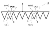
- the sound absorbing structure of the present invention is provided with a plurality of conical protrusions 1 having a hollow shape and having recesses 4 on the inside thereof in a predetermined arrangement.
- the plurality of conical protrusions 1 are rear protrusions 1X that protrude from the reference plane 6 in the back direction while positioning the openings of the recesses 4 on the reference plane 6, and the recesses 4 of the plurality of back protrusions 1X are In addition to being opened on the front side of the reference plane 6, it is formed in a conical shape whose opening area decreases in the depth direction.
- the term “conical shape” is used in a broad sense including not only a cone having a tip as a vertex but also a cone having a tip as a side and a frustum having a tip as a surface.
- the above sound-absorbing structure has the characteristics that it can be manufactured at a low cost with a simple structure and a light weight as a whole. That is, the sound absorbing structure described above has a plurality of conical protrusions that are hollow and have recesses on the inside, and a back protrusion that protrudes in the back direction with the opening of the recess positioned on the reference plane. This is because the rear protrusions are arranged in a predetermined arrangement so that the recesses are opened to the front side of the reference plane, and are formed in a cone shape whose opening area decreases in the depth direction. With the above configuration, there is an advantage that a hollow sound-absorbing structure can be formed to reduce the overall weight and cost.
- the sound absorbing structure having a predetermined size is mass-produced while being transported. By stacking them together, they can be efficiently transported without being bulky, and at the construction site, they can be easily and easily processed to the size required for the installation place by connecting them.
- a plurality of sound absorbing structures can be connected and processed into a predetermined shape, each sound absorbing structure can be manufactured to a size suitable for transportation, and a large number of sound absorbing structures can be carried to the site. Can be connected and assembled.
- the conical protrusions of the other sound absorbing structure can be fitted into the recesses of the one sound absorbing structure so that they can be easily connected and processed to a predetermined size. Therefore, the sound absorbing structure can be assembled and installed at an optimum size on the site without being restricted in size in manufacturing, transportation, installation work, and the like, and the connecting portion can be finished with a beautiful appearance. .
- the conical protrusion 1 has a plurality of back protrusions 1X protruding from the reference plane 6 in the back direction, and the recess 4 inside the hollow shape protruding from the reference plane 6 in the front direction. And a plurality of front protrusions 1Y.
- the front protrusion 1Y is provided without closing the opening of the back protrusion 1X, and the recess 4 of the front protrusion 1Y is opened on the back side of the reference plane 6 so as to open in the depth direction.
- the above sound-absorbing structure has the characteristics that it can be manufactured at a low cost with a simple structure and a light weight as a whole. That is, the above sound-absorbing structure has a plurality of conical protrusions that are hollow and have recesses on the inside, a back protrusion that protrudes in the back direction with the opening of the recess positioned on the reference plane, and a front direction.
- the front protrusion is formed in a state that does not close the opening of the rear protrusion, and the concave portion of the front protrusion is opened on the back side of the reference plane so as to face in the depth direction. This is because the opening area is reduced to a conical shape.
- a hollow conical protrusion can be formed from the reference plane so as to protrude on both the back side and the front side, and in addition to opening the recess of the back protrusion to the front side, the recess of the front protrusion can be formed. It can be opened also on the back side.
- the conical protrusions and the openings of the recesses can be arranged on either side of the front and back, so that the sound absorption performance can be exhibited on both the front and back sides.
- this sound absorbing structure is provided with a plurality of conical protrusions having recess openings on both the back side and the front side in a predetermined arrangement, a sound absorbing structure having a predetermined size is mass-produced.
- this sound absorbing structure is in a state in which the conical protrusions provided on both surfaces are fitted to each other, that is, the back protrusion of the other sound absorbing structure is inserted into the recess of the back protrusion of one of the sound absorbing structures.
- the sound absorbing structure can be stacked while being positioned easily, and can be connected and processed to a predetermined size.
- a some sound-absorbing structure can be connected with higher connection intensity
- the plurality of conical protrusions 1 can share the opening edges 5 of the concavities 4 of the conical protrusions 1 adjacent to each other, with the opening edges 5 of the concavities 4 being polygonal. .
- the above sound-absorbing structure can realize excellent sound-absorbing characteristics by arranging a large number of conical protrusions without gaps on the reference plane of the sound-absorbing structure.
- the concavity 4 of the conical protrusion 1 can be a quadrangular pyramid concavity 4A having a square opening edge 5.
- the quadrangular pyramid recess 4 ⁇ / b> A can be formed by four triangular surfaces 3 extending inward from the opening edge 5.
- the concave portion 4 of the conical protrusion 1 can be a honeycomb concave portion 4B in which the opening edge 5 has a honeycomb shape.
- the honeycomb concave portion 4B includes two inclined surfaces 2 formed by connecting two inclined surfaces 2X in a V shape, and two triangular surfaces 3 formed on both side edges of the two inclined surfaces 2, The two inclined surfaces 2 and the triangular surface 3 can be connected to each other at the boundary edge 3c to form an outer peripheral surface having a horizontal cross-sectional shape of a hexagon.
- the sound absorbing structure can connect the two inclined surfaces 2 of the adjacent honeycomb recesses 4B with the opening edge 5 and connect the triangular surfaces 3 of the adjacent honeycomb recesses 4B with the opening edge 5.
- the plurality of conical protrusions 1 can be integrally formed with a sheet material or plate material having a predetermined thickness.
- the plurality of conical protrusions can be integrally formed of a thin and light material, so that excellent sound absorbing characteristics can be realized while making the whole lightweight.
- the sound-absorbing structure of the present invention can be formed by press-molding a plurality of conical protrusions 1 with a base material sheet 11 made of a sheet material or a plate material.
- the above sound-absorbing structure can be integrally formed with a plurality of conical protrusions in a predetermined arrangement easily and easily.
- the sound absorbing structure is manufactured by press molding a sheet material or a plate material, it can be mass-produced efficiently and at low cost.
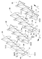
- the sound-absorbing structure of the present invention can be formed by bending and bonding the pattern sheets 22, 32, and 52 cut into a predetermined pattern from the plurality of conical protrusions 1.
- the above sound absorbing structure can be mass-produced extremely easily and easily at a low cost. This is because a pattern sheet cut into a predetermined pattern is bent and bonded to form a large number of conical protrusions.
- the sound absorbing structure of the present invention includes a plurality of conical protrusions 1 connected in a first direction at open edges 5 where adjacent conical protrusions 1 face each other and arranged in a line.
- the conical structure row 39 can be configured.
- This sound absorbing structure can connect the conical structure rows 39 adjacent to each other at the opening edge 5 facing each other to connect the plurality of conical structure rows 39 in the second direction. Since the above sound absorbing structure is formed by connecting a plurality of conical structure rows, it is possible to mass-produce each of the conical structure rows and connect them into a sound absorbing structure having a predetermined width. it can.
- the conical structure rows can be connected and manufactured to a predetermined width, the conical structure rows can be brought into the site and connected and assembled at the construction site. Therefore, it can be assembled and installed at an optimum size on site without being restricted in size in manufacturing, transportation, installation work, and the like. Further, since a plurality of conical structure rows are connected, different materials, materials, and characteristics can be used for each conical structure row, and these can be suitably combined.
- the sound-absorbing structure of the present invention can be formed by integrally forming a plurality of conical projections 1 by bending and bonding pattern sheets 22 and 52 cut into a predetermined pattern.
- 52 includes a protruding portion forming block 23 formed by connecting two inclined surfaces 2X forming the conical protruding portion 1 and four triangular surfaces 3 at a boundary edge 3c, and also connecting a plurality of protruding portion forming blocks 23 to each other. And can be formed into a single sheet. Since the above sound absorbing structure can be processed by forming the pattern sheet into a single sheet, it can be manufactured efficiently.
- the sheet material or the plate material can be any of paper, plastic, metal plate, and nonwoven fabric.
- the above sound-absorbing structure can be bent into a desired shape by bending it with paper or sheet material and making it bendable at each folding line.
- the sound absorbing structure having this structure is arranged along the cylinder or the curved surface as a curved shape by changing the bending angle of the bending line, or the sound absorbing structure can be expanded and contracted. can do.
- the outer peripheral surface and / or the inner peripheral surface of the cone-shaped projecting portion 1 is coated with one or more of a deodorant, a fragrance, an insecticide, a flame retardant, and an antioxidant.
- a deodorant e.g., peppermint, a sulfate, a sulfate, a sulfate, a sulfate, a sulfate, a sulfate, a sulfate, a sulfate, a sulfate, a stylitol, a nitride, nitride, nitride, nitride, nitride, nitride, nitride, nitride, nitride, nitride, nitride, nitride, nitride, nitride, nitride, nitride, nitride
- the sound absorbing structure of the present invention comprises two or more sound absorbing structures 10, 20, 30, 40, 50 according to any one of claims 1 to 11, which are stacked and connected to each other, and between the opposing reference planes 6.
- the hollow part 7 can be formed.
- the above sound-absorbing structure laminate has a simple structure because the sound-absorbing structure is formed by laminating a plurality of cone-shaped protrusions that are hollow and have recesses on the inside in a predetermined arrangement to provide a hollow portion inside.
- the whole can be made light and an excellent sound absorption characteristic can be realized by the hollow portion formed inside.
- this sound absorbing structure laminate is formed by laminating a plurality of sound absorbing structures and processed into a predetermined shape, the sound absorbing structure can be brought into the site and connected and assembled at the construction site. Therefore, it can be assembled and installed at the optimum size on site without being restricted by size in manufacturing, transportation, installation work, etc., and the connected part is made inconspicuous and finished with a beautiful appearance. be able to. Furthermore, since a plurality of sound absorbing structures are connected, different materials, materials, and characteristics can be used for each sound absorbing structure, and an ideal sound absorbing structure laminate can be realized by suitably combining them.
- the recess 4 of the cone-shaped protrusion 1 of the sound-absorbing structure is a honeycomb recess 4B having an opening edge 5 in a honeycomb shape
- the honeycomb recess 4B has two inclined surfaces 2X in a V shape.
- Two inclined surfaces 2 connected to each other, and two triangular surfaces 3 arranged on both side edges of the two inclined surfaces 2, and the two inclined surfaces 2 and the triangular surfaces 3 are connected to each boundary. It can connect with the edge 3c and can form the outer peripheral surface which makes a horizontal cross-sectional shape hexagon.
- the sound absorbing structure can connect the two inclined surfaces 2 of the conical protrusions 1 adjacent to each other with the opening edge 5 and connect the triangular surfaces 3 of the adjacent honeycomb recesses 4B with the opening edge 5. it can.
- the sound absorbing structures stacked on each other can be joined by laminating and adhering two opposing inclined surfaces 2.
- the sound-absorbing structure laminate of the present invention can connect sound-absorbing structures stacked on each other via side connecting members that are connected to the side surfaces.
- the intermediate laminate member 80 can be laminated between the sound absorbing structures 10, 20, 30, 40, and 50 laminated together.
- the intermediate laminated member 80 has one surface adhered to the rear protrusion 1X of the sound absorbing structure stacked on the front side, and the other surface attached to the front protruding portion 1Y of the sound absorbing structure stacked on the rear side. Can be glued.
- the intermediate laminated member 80 includes a plurality of rectangular tubes 82, and the outer peripheral surfaces of the rectangular tubes 82 are bonded and connected to the conical protrusions 1 of the sound absorbing structures 10 and 30 facing each other. be able to.
- the intermediate laminate member 80 can be a corrugated plate 83 having a zigzag cross-sectional shape.
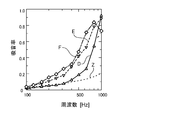
- FIGS. 1 and 4 are graphs showing the results of the sound absorption coefficient test of the sound absorbing structure and sound absorbing structure laminate of the present invention and the sound absorbing structure of the comparative example.
- the normal incident sound absorption coefficient was measured using a measuring apparatus based on the transfer function method.
- the sound absorbing structure of the present invention used for the sound absorption test was formed by bending and bonding a paper base sheet having a thickness of 0.15 mm to form a large number of conical protrusions in a predetermined arrangement. I used something.
- the sound absorbing structures of Example 1 and Example 2 are those in which only a back protrusion is provided as a conical protrusion on the reference plane, and Example 3 and Example 3 are implemented.
- the sound absorbing structure of Example 5 uses a reference plane provided with a back protrusion and a front protrusion as conical protrusions, and a sound absorbing structure laminate of Example 6
- a laminate of two sound absorbing structures of Example 5 shown in FIG. 10 is used, and the sound absorbing structure laminated body of Example 7 is shown in FIG.
- a laminate of three sound absorbing structures of Example 5 shown was used.
- the inner recess 4 is a square with one side of the square opening edge 5A being 15 mm in height (depth).
- a square pyramidal recess 4A having a regular pyramid shape of 18 mm.
- the inner concave portion 4 has a rectangular shape 2 with a lateral width (W) of 8 mm.
- a honeycomb concave portion 4B formed by connecting a triangular surface 3 having a common edge 3a of 15 mm to the side edge of the inclined surface 2 was formed.
- the interval between the opposing parallel edges 2a was 21 mm, and the height (depth) was 18 mm.
- a sound absorbing structure made of urethane having a shape in which a large number of conical convex portions are regularly arranged on the front surface was used.
- the convex portion had a bottom area of about 250 mm 2 and a height of 18 mm.
- FIG. 27 shows the sound absorption coefficient characteristics of the sound absorbing structures of Examples 1 and 2 of the present invention and the comparative example.
- curve A shows the sound absorption coefficient characteristic of the sound absorbing structure of Example 1
- curve B shows the sound absorption characteristic of the sound absorbing structure of Example 3
- curve Z shows the sound absorption characteristic of the sound absorbing structure of the comparative example.
- the sound absorbing structures of Example 1 and Example 2 of the present invention have 1.3 to 1.8 times the frequency around 800 Hz compared to the sound absorbing structure of the comparative example. In the vicinity of 1000 Hz, it has an excellent sound absorption coefficient characteristic of 1.8 to 2.5 times, and in a frequency range of 1000 Hz or higher, it has been demonstrated to have a high sound absorption coefficient of 50% or higher.
- FIG. 28 has shown the sound absorption coefficient characteristic of the sound-absorbing structure of Example 3 and Example 5 of this invention, and a comparative example.
- curve C represents the sound absorption coefficient characteristic of the sound absorbing structure of Example 3
- curve D represents the sound absorption characteristic of the sound absorbing structure of Example 5
- curve Z represents the sound absorption characteristic of the sound absorbing structure of the comparative example.
- Each rate characteristic is shown.
- the sound absorbing structures of Example 3 and Example 5 of the present invention have a frequency of 1.5 times or more near 500 Hz compared with the sound absorbing structure of the comparative example.
- FIG. 29 shows the sound absorption coefficient characteristics of the sound absorbing structure of Example 5 of the present invention, the sound absorbing structure laminates of Examples 6 and 7, and the sound absorbing structure of the comparative example.
- curve D represents the sound absorption coefficient characteristic of the sound absorption structure of Example 5
- curve E represents the sound absorption characteristic of the sound absorption structure laminate of Example 6
- curve F represents the sound absorption structure lamination of Example 7.
- the sound absorption characteristics of the body are shown
- the curve Z shows the sound absorption characteristics of the sound absorption structure of the comparative example.
- the frequency is 1.5 or more near 200 Hz and in the region of 300 to 400 Hz compared to the sound absorbing structure of the comparative example. It has been demonstrated that it has a sound absorption characteristic of 3 to 5 times in the region of 2 times or more and 500 to 1000 Hz, and a high sound absorption rate of 50% or more in the frequency region of 600 Hz or more.
- the sound absorbing structure laminate of Example 7 of the present invention has a sound absorption coefficient characteristic that is 2.5 or more when the frequency is around 200 Hz, and 3 to 5 times higher in the region of 300 to 1000 Hz than the sound absorbing structure of the comparative example.
- the sound-absorbing structure and sound-absorbing structure laminate of the present invention have excellent sound-absorbing characteristics compared to conventional sound-absorbing structures, and in particular, have excellent sound-absorbing characteristics in a low frequency range. Recognize.
- the conventional sound absorbing structure the sound insulation performance has been improved by increasing the density with a solid material.
- a unique structure in which hollow conical protrusions having recesses on the inside are provided in a predetermined arrangement. This structure achieves excellent sound absorption characteristics. For this reason, as a simple structure, there is a feature that an excellent sound absorption coefficient characteristic can be realized while being mass-produced at a low weight and at a low cost. In particular, it is possible to ideally improve the sound insulation characteristics in the bottom frequency region where sound insulation is difficult for the high frequency region.
- FIG. 2 is a cross-sectional view of the sound absorbing structure shown in FIG. 1 taken along the line II-II. It is an expansion perspective view which shows the cone-shaped protrusion part of the sound-absorbing structure shown in FIG. It is a perspective view of the sound absorption structure concerning Example 2 of this invention. It is an expansion perspective view which shows the cone-shaped protrusion part of the sound-absorbing structure shown in FIG. It is a perspective view of the sound absorption structure concerning Example 3 of this invention.
- FIG. 7 is a cross-sectional view of the sound absorbing structure shown in FIG. 6 taken along the line VII-VII.
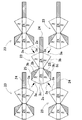
- FIG. 2 is an exploded cross-sectional view showing an example of a press die for forming the sound absorbing structure shown in FIG. 1.
- FIG. 7 is an exploded cross-sectional view showing an example of a press die for forming the sound absorbing structure shown in FIG. 6.
- FIG. 6 is an expanded view which shows an example of the pattern sheet which manufactures the sound-absorbing structure shown in FIG.
- FIG. 11 is a cross-sectional view showing a state in which the sound absorbing structure shown in FIG. 10 is expanded and contracted in the front-rear direction, corresponding to a cross section taken along line XVIII-XVIII of the sound absorbing structure shown in FIG.
- FIG. 11 is a disassembled perspective view which shows the state which divided
- the sound absorbing structure of the present invention is applied to building structures such as walls, doors, ceilings and floors, partitions and blinds, interior decorations such as accordion curtains, surface covers, and soundproof walls arranged on the side surfaces of roads and railway lines. Used as these surface materials.
- This sound absorbing structure can be used as a single layer, or a plurality of sound absorbing structures can be used as a sound absorbing structure laminate.
- FIG. 1 is a perspective view of the sound absorbing structure according to the first embodiment
- FIG. 2 is a cross-sectional view taken along the line II-II of the sound absorbing structure shown in FIG. 1
- FIG. 3 is an enlarged view of the conical protrusion of the sound absorbing structure shown in FIG. 4 is a perspective view of the sound absorbing structure according to the second embodiment.
- FIG. 5 is an enlarged perspective view of the cone-shaped protrusion of the sound absorbing structure shown in FIG. 4.
- FIG. 6 is a perspective view of the sound absorbing structure according to the third embodiment.
- FIG. 7 is a sectional view taken along the line VII-VII of the sound absorbing structure shown in FIG. 6, FIG.
- FIG. 8 is an enlarged perspective view of the cone-shaped protrusion of the sound absorbing structure shown in FIG. 6, and FIG. FIG. 10 is a perspective view of the sound absorbing structure according to the fifth embodiment, and FIG. 11 is an enlarged perspective view of the conical protrusion of the sound absorbing structure shown in FIG.
- the sound absorbing structure shown in these drawings shows a state where the upper surface is the sound source side, that is, a state where the upper surface is the sound absorbing surface.
- the sound absorbing structures 10 and 20 shown in FIGS. 1, 2, and 4 are provided with a plurality of conical protrusions 1 that are hollow and have recesses 4 on the inside thereof, arranged regularly.
- the sound absorbing structures 10 and 20 shown in FIGS. 1, 2, and 4 have a plurality of conical protrusions 1, and the openings of the recesses 4 are positioned on the reference plane 6, and from the reference plane 6 to the back direction.
- the rear protruding portion 1X protrudes.
- the back protrusion 1X in the figure has a cup shape with a hollow recess 4 on the inside.
- the recesses 4 of the plurality of rear protrusions 1X are opened to the front side of the reference plane 6, and are formed in a conical shape whose opening area decreases in the depth direction.
- the sound absorbing structures 10 and 20 shown in the figure have a polygonal shape at the opening edge 5 of the recess 4 of the conical protrusion 1, and are connected so as to share the opening edges 5 of the recesses 4 adjacent to each other.
- the opening edge 5 of the recessed part 4 of the cone-shaped protrusion part 1 is arrange
- a plurality of conical protrusions 1 are integrally formed of a sheet material or a plate material having a predetermined thickness.
- the sound absorbing structures 10 and 20 are manufactured by processing a sheet material or a plate material such as paper, plastic, metal plate, or nonwoven fabric into a predetermined uneven shape.
- a sound absorbing structure 10 shown in FIGS. 1 and 2 is provided with a quadrangular pyramid recess 4A having a horizontal cross-sectional shape of a quadrangle on the inner side of a back projection 1X which is a cone-shaped projection 1.
- the illustrated sound absorbing structure 10 is provided with a large number of quadrangular pyramid recesses 4A each having a square opening edge 5 arranged regularly and vertically.
- the quadrangular pyramid recess 4A of the back projection 1X has the square opening edge 5A positioned on the reference plane 6 and has a vertex arranged on the back side as a quadrangular pyramid projecting toward the back side.
- the sound absorbing structure 10 shown in the figure is connected so as to share the square opening edge 5A of the quadrangular pyramid recesses 4A adjacent to each other on the reference plane 6, and the openings of the numerous quadrangular pyramid recesses 4A are arranged on the front side.
- the vertical direction is the vertical direction in the figure, and means the direction in which the conical protrusions 1 protrude with respect to the reference plane 6. Therefore, the horizontal cross section of the conical protrusion 1 means a cut surface in a plane parallel to the reference plane 6.
- the quadrangular pyramid recess 4 ⁇ / b> A of the rear protrusion 1 ⁇ / b> X is formed by four triangular surfaces 3 that extend inward from the square opening edge 5 ⁇ / b> A.
- the triangular surface 3 has one side as a shared edge 3a constituting the square opening edge 5A, and the other two sides as boundary edges 3b of the adjacent triangular surface 3.
- the four triangular surfaces 3 are connected by opposing boundary edges 3b having the same length to form a quadrangular pyramid recess 4A, and the four shared edges 3a form a square opening edge 5A.
- each triangular surface 3 is a congruent isosceles triangle
- the entire shape is a regular quadrangular pyramid.
- the quadrangular pyramid concave portion of the rear protrusion does not necessarily have to be a regular quadrangular pyramid, and all the four triangular surfaces may have different shapes or a combination of congruent triangular surfaces and noncongruent triangles.
- the quadrangular pyramid recess of the rear protrusion does not necessarily have a square opening edge, but may be a rhombus, rectangle, trapezoid, or parallelogram. Therefore, the shape of the triangular surface that forms the quadrangular pyramid recess of the back protrusion also varies depending on the shape of the square opening edge.
- the sound absorbing structure 10 shown in FIGS. 1 and 2 on the reference plane 6, a large number of quadrangular pyramid recesses 4 ⁇ / b> A of the rear protrusions 1 ⁇ / b> X are regularly arranged in the vertical and horizontal directions. That is, the sound absorbing structure 10 has a large number of back protrusions 1X arranged in the vertical direction and the horizontal direction intersecting each other.
- the vertical direction is the extension direction (the x-axis direction in FIG. 1) of one of the two shared edges 3a that are two adjacent sides of the square opening edge 5A
- the horizontal direction is a square.
- the extending direction of the other shared edge 3a of the opening edge 5A is the y-axis direction in FIG.
- the sound absorbing structure 10 shown in FIGS. 1 and 2 has a square opening edge 5A of the rear protrusion 1X as a square, the vertical direction and the horizontal direction, which are extension directions of two adjacent sides of the square opening edge 5A, are The direction is orthogonal.
- the sound absorbing structure does not limit the square opening edge of the rear protrusion to a square, the vertical direction and the horizontal direction, which are extension directions of two adjacent sides of the square opening edge, are not necessarily orthogonal.
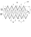
- the sound absorbing structure 20 shown in FIG. 4 is provided with a honeycomb concave portion 4B having a horizontal cross-sectional shape of a honeycomb shape inside the back surface protruding portion 1X which is the cone-shaped protruding portion 1.
- the sound absorbing structure 20 shown in the figure is provided with a large number of honeycomb recesses 4B having an opening edge 5 in a honeycomb shape and arranged regularly in a honeycomb shape.
- the honeycomb recess 4B of the back protrusion 1X has the honeycomb opening edge 5B positioned on the reference plane 6 and has a top portion arranged on the back side as a substantially hexagonal pyramid shape protruding toward the back side.
- the sound absorbing structure 20 shown in the figure is connected so as to share the honeycomb opening edges 5B of the adjacent honeycomb recesses 4B on the reference plane 6, and the openings of the many honeycomb recesses 4B are arranged on the front side. .
- the honeycomb recess 4 ⁇ / b> B of the rear protrusion 1 ⁇ / b> X is arranged on two inclined surfaces 2 formed by connecting two inclined surfaces 2 ⁇ / b> X in a V shape and on both side edges of the two inclined surfaces 2. It is composed of two triangular surfaces 3 each.
- the honeycomb concave portion 4B of the rear protrusion 1X has an inner peripheral surface in which the horizontal cross-sectional shape is hexagonal by connecting the two inclined surfaces 2 and the triangular surface 3 at the respective boundary edges 3c.
- the honeycomb recess 4B of the rear protrusion 1X shown in the figure has a rectangular inclined surface 2X, two rectangles constituting the two inclined surfaces 2, and two connected to one side edge of the two inclined surfaces 2.
- the inner peripheral surface is formed by six surfaces including the triangular surface 3 and two triangular surfaces 3 connected to the other side edge of the two inclined surfaces 2.
- the opening edge 5 of the honeycomb recessed part 4B of the back protrusion part 1X has a hexagonal shape with the parallel edge 2a and the shared edge 3a as a shape in which the parallel edges 2a arranged in parallel to each other are connected by the zigzag shared edge 3a.
- the honeycomb opening edge 5B is formed.
- the two inclined surfaces 2 of the honeycomb recessed portion 4 ⁇ / b> B have a shape that extends inward from the parallel edges 2 a and is inclined downward toward the center between the two parallel edges 2 a facing each other.
- the two inclined surfaces 2 of the honeycomb recess 4B shown in the figure have a shape formed by connecting two rectangles in a V shape.
- the two inclined surfaces 2 composed of two rectangles form a parallel edge 2a with the first side of the rectangle located at the upper edge of the V-shape, and the third side of the rectangle located at the lower edge of the V-shape.
- the bottom line 2b is configured, and further, a boundary edge 3c between the triangular surface 3 adjacent to the rectangular second side and the fourth side located on both sides of the two inclined surfaces 2 is configured.
- the two triangular surfaces 3 connected to the adjacent side edges of the two inclined surfaces 2 are the boundary edges 3c connecting the first side to the side edges of the two inclined surfaces 2 and the second side is the adjacent triangular surface 3.
- the boundary edge 3b is the mutual edge 3b
- the third side is the shared edge 3a of the honeycomb opening edge 5B.
- the honeycomb recess 4B is formed by adjusting the ratio of the lengths of the first side, the second side, and the third side of the two triangular surfaces 3 connected to the side edges of the two inclined surfaces 2 to form a honeycomb.
- the hexagonal shape that is the horizontal cross-sectional shape of the recess 4B can be adjusted.
- the two inclined surfaces 2X have a congruent rectangle, and two triangular surfaces 3 arranged on both side edges of the rectangle are all congruent triangles.
- the honeycomb recess 4B can be formed in a line-symmetric and point-symmetric shape in plan view.
- a large number of congruent inclined surfaces 2X and triangular surfaces 3 are regularly arranged. Excellent design can be realized with a beautiful and beautiful appearance.
- the honeycomb recessed part of the back protrusion part does not necessarily need to make two inclined surfaces into a congruent rectangle, and it can be a congruent trapezoid or a parallelogram, or a rectangle, a trapezoid, or a parallelogram with different shapes. You can also Therefore, the shape of the four triangular surfaces connected to both side edges of the two inclined surfaces can be variously changed according to the shape of the inclined surface.
- the honeycomb recess 4B of the rear protrusion 1X shown in FIG. 5 has a rectangular width 2W of the inclined surface 2X shorter than the shared edge 3a of the triangular surface 3, and the overall shape of the honeycomb recess 4B is a quadrangular pyramid. The shape is approximated.
- the rear protrusion 1X can reduce the opening area with respect to the depth of the honeycomb recess 4B, and can sharpen the entire rear protrusion 1X.
- the honeycomb recess 4B of the rear protrusion 1X can make the width (Ws) of the bottom line 2b of the two inclined surfaces 2 close to zero.
- the lateral width (W) of the inclined surfaces is gradually narrowed from the parallel edge toward the bottom line so that the lateral width (Ws) at the top of the rear protrusion is close to zero.
- This back protrusion can be formed into a hexagonal pyramid shape in which all the sides in the horizontal section become gradually smaller toward the tip, with the shape of the inclined surface being a tapered isosceles trapezoid. Further, the back protrusion can be formed in a hexagonal pyramid shape with the lateral width (Ws) at the top being 0, that is, the inclined surface constituting the two inclined surfaces of the honeycomb concave portion is a triangle and the tip is the apex.
- the illustrated sound absorbing structure 20 connects a number of rear protrusions 1X in the front-rear direction and the left-right direction that intersect each other.
- the front-rear direction is a direction (y-axis direction in FIG. 4) orthogonal to the parallel edge 2a constituting the honeycomb opening edge 5B
- the left-right direction is an extension direction of the parallel edge 2a (x-axis direction in FIG. 4). It is said.
- the sound absorbing structure 20 in FIG. 4 is configured by connecting two inclined surfaces 2 of the rear protrusions 1X adjacent in the front-rear direction with the parallel edges 2a facing each other, and connecting a large number of two inclined surfaces 2 in the front-rear direction. While extending, the back surface protrusions 1X adjacent in the left-right direction are shifted by a half pitch in the front-rear direction, and are connected to each other in a state in which the opposing shared edges 3a are fitted.
- the honeycomb recesses 4B adjacent to each other are connected by the parallel edge 2a and the shared edge 3a, and the large number of back protrusions 1X are connected so that the honeycomb opening edge 5B is located on the same plane.
- the above sound absorbing structures 10 and 20 shown in FIG. 1, FIG. 2 and FIG. 4 are installed in such a posture that the openings of the numerous recesses 4 arranged on the reference plane 6 are on the sound source side. That is, the sound absorbing structures 10 and 20 use the reference plane 6 on which the openings of the many recesses 4 are arranged as the sound absorbing surface.
- the sound absorbing structures 30, 40, 50 shown in FIGS. 6, 7, 9, and 10 have a plurality of conical protrusions 1 that are hollow and have recesses 4 inside, and the openings of the recesses 4 have openings.
- the rear projection 1X is located on the reference plane 6 and projects from the reference plane 6 in the rear direction
- the front projection 1Y projects from the reference plane 6 in the front direction.
- the sound absorbing structures 30, 40, 50 shown in the drawing have a cap shape in which the rear protrusion 1 ⁇ / b> X has a cup shape having a hollow recess 4 inside and the front protrusion 1 ⁇ / b> Y has a hollow recess 4 inside. Yes.
- the sound absorbing structures 30, 40, 50 are arranged adjacent to each other on the reference plane 6 so that the plurality of rear surface protrusions 1 ⁇ / b> X and the plurality of front surface protrusions 1 ⁇ / b> Y do not close each other's openings.
- the recesses 4 of the plurality of rear protrusions 1X are opened to the front side of the reference plane 6, and are formed in a conical shape whose opening area decreases in the depth direction.
- the recesses 4 of the plurality of front protrusions 1Y are opened on the back side of the reference plane 6 and are formed in a cone shape whose opening area decreases in the depth direction. That is, the front protrusion 1Y is formed in a conical shape whose cross-sectional shape decreases in the protrusion direction.
- the sound absorbing structures 30 and 50 have the shape of the front protrusion 1 ⁇ / b> Y that is the shape in which the rear protrusion 1 ⁇ / b> X is inverted up and down in the drawing. That is, the front protrusion 1 ⁇ / b> Y and the back protrusion 1 ⁇ / b> X are congruent with each other and are arranged in a posture protruding in the opposite direction with respect to the reference plane 6.
- the sound absorbing structures 30 and 50 having the shape in which the front protrusion 1Y and the rear protrusion 1X are inverted with respect to the reference plane 6 can be conveniently used with the front and back being the same shape.
- the recessed part 4 of the back protrusion part 1X can be made into the same shape as the recessed part 4 of the above-mentioned back protrusion part 1X. Moreover, since the recessed part 4 of the back protrusion part 1X is made into the shape which turned upside down also about the recessed part 4 of the front protrusion part 1Y, it can be set as the same shape as the recessed part 4 of the back protrusion part 1X. However, the back protrusion and the front protrusion do not necessarily need to be congruent. Like the sound absorbing structure 40 shown in FIG. 9, the front protrusion 1 ⁇ / b> Y and the back protrusion 1 ⁇ / b> X can have different shapes. For example, the front protrusion and the rear protrusion can have different recess depths and inner shapes while having the same opening edge.
- the sound absorbing structures 30, 40, and 50 have a polygonal shape of the opening edge 5 of the concave portion 4 of the rear protrusion 1 ⁇ / b> X and the front protrusion 1 ⁇ / b> Y, and are adjacent to each other.
- the opening edge 5 of the recessed part 4 of the some cone-shaped protrusion part 1 is arrange
- the sound absorbing structures 30, 40, 50 in these drawings also integrally form the plurality of conical protrusions 1 with a sheet material or plate material having a predetermined thickness.
- the recesses 4 of the rear protrusion 1X and the front protrusion 1Y are formed as a quadrangular pyramid recess 4A having a square opening edge 5.
- the illustrated sound absorbing structure 30 is provided with a large number of back protrusions 1X and front protrusions 1Y, each having an opening edge 5 that is a quadrangle, alternately arranged vertically and horizontally.
- the quadrangular pyramid recess 4A of the back projection 1X has the square opening edge 5A positioned on the reference plane 6 and has a vertex arranged on the back side as a quadrangular pyramid projecting toward the back side.
- the quadrangular pyramid recess 4A of the front protrusion 1Y has the square opening edge 5A positioned on the reference plane 6 and has a vertex arranged on the front side as a quadrangular pyramid protruding toward the front side.
- the sound absorbing structure 30 shown in the figure is connected to the reference plane 6 so as to share the square opening edges 5A of the back protrusion 1X and the front protrusion 1Y adjacent to each other, and the quadrangular pyramid recess 4A of the back protrusion 1X is connected to the front.
- the quadrangular pyramid recesses 4A of the front protrusion 1Y are arranged open on the back side.
- the quadrangular pyramid recess 4A of the rear projection 1X and the quadrangular pyramid recess 4A of the front projection 1Y are formed by four triangular surfaces 3 extending inward from the square opening edge 5A.
- the triangular surface 3 has one side as a supply edge 3a constituting the square opening edge 5A, and the other two sides as boundary edges 3b of the adjacent triangular surface 3.
- the four triangular surfaces 3 are connected by opposing boundary edges 3b having the same length to form a quadrangular pyramid recess 4A, and the four shared edges 3a form a square opening edge 5A.
- the quadrangular pyramid recess 4A of the rear protrusion 1X shown in FIG. 8 has a square opening edge 5A in a square shape, and each triangular surface 3 has a congruent isosceles triangle, and the entire shape is a regular quadrangular pyramid.
- the quadrangular pyramid recess 4A of the front protrusion 1Y also has a square opening edge 5A in a square shape, and each triangular surface 3 has a congruent isosceles triangle, and the entire shape is a regular quadrangular pyramid.
- the sound absorbing structure 30 in which the quadrangular pyramid recesses 4A of all the rear protrusions 1X are congruent regular quadrangular pyramids, and the quadrangular pyramid recesses 4A of all the front protrusions 1Y are congruent regular quadrangular pyramids An excellent design can be realized as a geometrically beautiful appearance in which congruent regular quadrangular pyramids are regularly arranged.
- the back protrusion and the front protrusion do not necessarily have to be regular quadrangular pyramids, and the four triangular surfaces may all have different shapes, or a combination of congruent triangular surfaces and non-congruent triangles.
- the back protrusion and the front back protrusion do not necessarily have a square square opening edge, and may be a rhombus, rectangle, trapezoid, or parallelogram. Therefore, the shape of the triangular surface that forms the rear protrusion and the front protrusion is also variously changed according to the shape of the square opening edge.
- the sound absorbing structure 30 shown in FIG. 6 and FIG. 7 has a back protrusion 1X and a front protrusion 1Y provided on both sides in a congruent shape. That is, the front protrusion 1Y has a shape in which the back protrusion 1X is turned upside down, and the triangular surface 3 forming the front protrusion 1Y and the triangular surface 3 forming the back protrusion 1X are all congruent triangles.
- the sound absorbing structure 30 having this structure makes the protrusion amount and the inclination of the back protrusion 1X and the front protrusion 1Y adjacent to each other equal.
- the structure in which the adjacent back surface protruding portion 1X and front surface protruding portion 1Y are congruent quadrangular pyramids is a state in which the two opposing triangular surfaces 3 are connected by the shared edge 3a and bent at the shared edge 3a.
- the two triangular surfaces 3 can be connected in a planar shape to form a rhombus or a parallelogram. Therefore, the two triangular surfaces 3 connected at the boundary between the back protrusion 1X and the front protrusion 1Y adjacent to each other can have a beautiful appearance without a bent line.
- the shared edge 3a is shown by a broken line for easy understanding.
- Example 4 it is not always necessary for the sound absorbing structure to have the same height and inclination of the rear protrusion and the front protrusion formed on both sides.
- the height and inclination of the back protrusion and the front protrusion formed so as to protrude from both surfaces of the sound absorbing structure can also be changed.
- An example of such a sound absorbing structure is shown in FIG.
- the front projecting portion 1Y and the rear projecting portion 1X of the sound absorbing structure 40 shown in this figure have the same shape of the square opening edge 4A of the quadrangular pyramid recess 4A, but have different depths of the quadrangular pyramid recess 4A.
- the shape of the triangular surface 3 which forms the back protrusion part 1X and the front protrusion part 1Y differs.
- the sound absorbing structure 40 formed by connecting these triangular surfaces 3 to each other has two triangular surfaces 3 that are connected at the boundary between the back protrusion 1X and the front protrusion 1Y adjacent to each other. However, it becomes a structure bent in the shared edge 3a.
- the sound absorbing structures 30 and 40 have a large number of rear protrusions 1X and front protrusions 1Y arranged alternately and vertically on the reference plane 6. That is, in the sound absorbing structures 30 and 40, the rear protrusions 1X and the front protrusions 1Y are alternately arranged in the vertical direction, and the rear protrusions 1X and the front protrusions 1Y are alternately arranged in the horizontal direction.
- the vertical direction is the extension direction (the x-axis direction in FIGS. 6 and 9) of one of the two shared edges 3a that are two adjacent sides of the square opening edge 5A
- the recesses 4 of the rear protrusion 1X and the front protrusion 1Y are formed as honeycomb recesses 4B having an opening edge 5 in a honeycomb shape.
- the illustrated sound absorbing structure 50 is provided with a large number of rear protrusions 1X and front protrusions 1Y having an opening edge 5 in a honeycomb shape and arranged regularly in a honeycomb shape.
- the honeycomb recess 4B of the back protrusion 1X has the honeycomb opening edge 5B positioned on the reference plane 6 and has a top portion arranged on the back side as a substantially hexagonal pyramid shape protruding toward the back side.
- the honeycomb recess 4B of the front protrusion 1Y has the honeycomb opening edge 5B positioned on the reference plane 6 and has a top portion arranged on the front side as a substantially hexagonal pyramid shape protruding toward the front.
- the sound absorbing structure shown in the figure is connected so that the honeycomb opening edges 5B of the conical protrusions 1 adjacent to each other are shared on the reference plane 6, and the honeycomb recessed part 4B of the rear protrusion 1X protrudes frontward.
- the honeycomb concave portions 4B of the portion 1Y are opened on the back side.
- the honeycomb recessed portion 4B of the rear protruding portion 1X and the honeycomb recessed portion 4B of the front protruding portion 1Y include two inclined surfaces 2 formed by connecting two inclined surfaces 2X in a V shape, and the two inclined surfaces. 2 is formed of two triangular surfaces 3 arranged on both side edges.
- the honeycomb recessed portion 4B of the rear protruding portion 1X and the honeycomb recessed portion 4B of the front protruding portion 1Y are formed by connecting these two inclined surfaces 2 and the triangular surface 3 at respective boundary edges 3c so that the horizontal sectional shape is a hexagon.
- a peripheral surface is formed.
- the inclined surface 2X is rectangular, and two rectangles constituting the two inclined surfaces 2 and one of the two inclined surfaces 2 are formed.
- the inner peripheral surface is formed by six surfaces including two triangular surfaces 3 connected to the side edges and two triangular surfaces 3 connected to the other side edge of the two inclined surfaces 2. .
- the two inclined surfaces 2 of the honeycomb concave portion 4B of the rear protruding portion 1X have a shape that is inclined downward from the two parallel edges 2a facing each other toward the center.
- the two inclined surfaces 2 of the honeycomb recessed portion 4B of the back surface protruding portion 1X shown in the figure are formed by connecting two rectangles in a V shape, forming a parallel edge 2a with the side located at the upper edge of the V shape,
- the bottom line 2b is constituted by the side located at the lower end edge of the V shape, and the boundary edge 3c with the adjacent triangular surface 3 is constituted by the sides located at both sides of the two inclined surfaces 2. Further, as shown in FIG.
- the two inclined surfaces 2 of the honeycomb concave portion 4B of the front protruding portion 1Y have a shape that inclines upwardly from the two parallel edges 2a facing each other.
- the two inclined surfaces 2 of the honeycomb recessed portion 4B of the front protrusion 1Y shown in the figure connect two rectangles in an inverted V shape, and form a parallel edge 2a with the side located at the lower end edge of the inverted V shape.
- the bottom line 2b is constituted by the side located at the upper edge of the inverted V shape
- the border edge c with the adjacent triangular face 3 is constituted by the sides located at both sides of the two inclined surfaces 2.
- the two triangular surfaces 3 connected to the adjacent side edges of the two inclined surfaces 2 are the boundary edges 3c connecting the first side to the side edges of the two inclined surfaces 2 and the second side is the adjacent triangular surface 3.
- the boundary edge 3b is a boundary edge 3b
- the third edge is a common edge 3a of the honeycomb opening edge 5B.
- the honeycomb recess 4B is formed by adjusting the ratio of the lengths of the first side, the second side, and the third side of the two triangular surfaces 3 connected to the side edges of the two inclined surfaces 2 to form a honeycomb.
- the hexagonal shape that is the horizontal cross-sectional shape of the recess 4B can be adjusted.
- the honeycomb recess 4B of the back protrusion 1X and the front protrusion 1Y shown in FIG. 11 has two inclined surfaces 2X having a congruent rectangle and two triangular surfaces 3 arranged on both side edges of the rectangle. All are congruent triangles.
- the honeycomb recess 4B can be formed in a line-symmetric and point-symmetric shape in plan view. As described above, in the sound absorbing structure 50 in which all the rear protrusions 1X and the front protrusions 1Y are line-symmetric and point-symmetric, a large number of congruent inclined surfaces 2X and triangular surfaces 3 are regularly arranged. Excellent design can be realized as a beautiful geometric appearance.
- the rear and front protrusions do not necessarily require the two inclined surfaces to be congruent rectangles, but can also be congruent trapezoids or parallelograms, or different shapes, rectangles, trapezoids, or parallelograms. It can also be. Therefore, the shape of the four triangular surfaces connected to both side edges of the two inclined surfaces can be variously changed according to the shape of the inclined surface.
- the honeycomb recess 4B of the rear protrusion 1X and the front protrusion 1Y shown in FIG. 11 has a lateral width (W) of the rectangular inclined surface 2X shorter than the shared edge 3a of the triangular surface 3, so that the honeycomb recess 4B
- the overall shape is approximated to a quadrangular pyramid shape.
- the rear projecting portion 1X and the front projecting portion 1Y can make the rear projecting portion 1X and the front projecting portion 1Y sharper by reducing the opening area with respect to the depth of the honeycomb recess 4B.
- the rear protrusion 1X and the front protrusion 1Y can make the width (Ws) of the bottom line 2b of the two inclined surfaces 2 close to zero.
- the rear protrusion 1X and the front protrusion 1Y have a hexagonal pyramid with the lateral width (Ws) at the top being 0, that is, the inclined surface 2X constituting the two inclined surfaces 2 of the honeycomb recess 4B as a triangle and the tip as the apex. It can also be made into a shape.
- the rear protrusion 1X and the front protrusion 1Y provided on both sides have a congruent shape. That is, the front protrusion 1Y has a shape in which the rear protrusion 1X is inverted upside down, and the inclined surface 2X and the triangular surface 3 forming the front protrusion 1Y and the inclined surface 2X and the triangular surface 3 forming the rear protrusion 1X are all combined. Shape.
- the sound absorbing structure 50 having this structure makes the protrusion amount and the inclination of the back protrusion 1X and the front protrusion 1Y adjacent to each other equal.
- the structure which makes back projection part 1X and front projection part 1Y congruent is the state where two opposing triangular surfaces 3 are connected by common edge 3a, without bending at this common edge 3a.
- Two triangular surfaces 3 can be connected in a planar shape to form a rhombus or a parallelogram. Therefore, the two triangular surfaces 3 connected at the boundary between the back protrusion 1X and the front protrusion 1Y adjacent to each other can have a beautiful appearance without a bent line.
- the shared edge 3a is indicated by a broken line for easy understanding.
- it is not always necessary for the sound absorbing structure to have the same height and inclination of the rear protrusion and the front protrusion formed on both sides. The height and inclination of the back protrusion and the front protrusion formed so as to protrude from both surfaces of the sound absorbing structure can also be changed.
- the illustrated sound absorbing structure 50 connects a large number of rear protrusions 1X and front protrusions 1Y in the front-rear direction and the left-right direction that intersect each other.
- the front-rear direction is a direction (y-axis direction in FIG. 10) orthogonal to the parallel edge 2a constituting the honeycomb opening edge 5B
- the left-right direction is an extension direction of the parallel edge 2a (x-axis direction in FIG. 10). It is said.
- the sound absorbing structure 50 in FIG. 10 extends in the front-rear direction by connecting the two inclined surfaces 2 of the rear protrusions 1X adjacent in the front-rear direction with the parallel edges 2a facing each other, and is adjacent to the front protrusion in the front-rear direction.
- the two inclined surfaces 2 of the portion 1Y are connected to each other by parallel edges 2a facing each other and connected in the front-rear direction, and the back-side protruding portion 1X and the front-side protruding portion 1Y adjacent in the left-right direction are shifted by a half pitch in the front-rear direction. These are connected to each other in a state in which the shared edges 3a facing each other are fitted. As described above, the adjacent cone-shaped protrusions 1 are connected such that the honeycomb opening edges 5B are connected by the parallel edges 2a and the shared edges 3a, and the honeycomb opening edges 5B are located on the same plane. .
- the above sound-absorbing structures 30, 40, and 50 shown in FIGS. 6, 7, 9, and 10 are the opening of the recess 4 of the back protrusion 1X and the protrusion of the front protrusion 1Y arranged on the reference plane 6. It is installed with the posture that the part becomes the sound source side. That is, in these sound absorbing structures, the reference plane 6 on which the opening of the rear protrusion 1X and the protrusion of the front protrusion 1Y are arranged is used as the sound absorbing surface.
- the sound absorbing structure 10, 20, 30, 40, 50 formed from a sheet material or plate material having a predetermined thickness is either the outer peripheral surface or the inner peripheral surface of the conical protrusion 1, or Various drugs can be applied to both.
- an agent any one or more of a deodorant, a fragrance, an insecticide, a flame retardant, an antioxidant, a paint, and the like can be applied.
- the sound absorbing structure formed by applying the drug to the surface of the cone-shaped protrusion 1 can be made multifunctional by applying the drug according to the application and purpose.
- a sound absorbing structure in which a sheet material or a plate material is made of paper or non-woven fabric can be effective for a long time by impregnating the surface of the cone-shaped protruding portion 1 with a drug to be applied.
- a sound absorbing structure in which a sheet material or a plate material is paper, plastic, or a metal plate can exhibit its effectiveness efficiently by attaching a drug to be applied to the surface of the cone-shaped protrusion 1.
- the sound absorbing structure can have a beautiful appearance by coloring the surface with a paint or the like.
- a sheet material or a plate material made of any one of paper, plastic, metal plate, and nonwoven fabric is processed into a predetermined concavo-convex shape to form a large number of conical protrusions.
- a sound absorbing structure made of a sheet material or a plate material is manufactured as follows.
- the sound absorbing structure is formed by pressing a base sheet 11 made of any one of paper, plastic, metal plate, and non-woven fabric from both sides with a pair of press dies 70 to form a large number of cones.
- the protrusion 1 can be integrally formed in a predetermined arrangement.
- the base sheet 11 that is press-molded and made of paper, plastic, or metal plate is made of a sheet material or thickness that can be bent by press molding.
- a base sheet made of non-woven fabric a base sheet made by applying or spraying a binder to the non-woven fabric or curing a non-woven fabric immersed in a liquid containing the binder to form a sheet can be used. Further, the strength of the paper base sheet can be improved by applying or spraying a binder on the surface or curing a material immersed in a liquid containing the binder.
- a base sheet made of plastic can be molded into a predetermined shape by pressing a plastic plate molded to a predetermined thickness while heating and deforming it, or by laminating a plurality of plastic sheets.
- the laminated plastic sheets can be molded into a predetermined shape by applying pressure while heating.
- a plurality of non-woven fabrics or papers can be press-molded while being heated with a plastic sheet that is thermally melted between them, and formed into a predetermined shape.
- This structure can be reinforced by connecting a plurality of non-woven fabrics or paper sheets with a plastic sheet that is heated and melted as a binder.
- the pair of press dies 70 includes a first press die 71 that molds the front side of the sound absorbing structures 10 and 30, and a second press that molds the back side of the sound absorbing structures 10 and 30. It consists of a press die 72. 12 shows a press die 70A for molding the sound absorbing structure 10 shown in FIG. 1, and FIG. 13 shows a press die 70B for molding the sound absorbing structure 30 shown in FIG.
- a press die 70A shown in FIG. 12 presses the base sheet 11 from both sides with a first press die 71A and a second press die 72A, and a large number of back protrusions 1X that are conical protrusions 1 are arranged in a predetermined arrangement. Molded in one piece.
- the first press die 71A is provided with first forming convex portions 73 for forming the concave portions 4 of the rear protruding portion 1X in a predetermined arrangement in the vertical and horizontal directions
- the second press die 72A is formed on the outer peripheral surface of the rear protruding portion 1X.
- the first molding recesses 74 are provided in a predetermined arrangement vertically and horizontally.
- the first molding convex portion 73 and the first molding concave portion 74 that mold the rear protrusion 1X are arranged at positions facing each other.
- molds are making the external shape of the 1st shaping
- the inner shape of the first molding recess 74 is a shape that follows the outer shape of the rear protrusion 1X to be molded. Since the sound absorbing structure 10 shown in FIG.
- the press die 70A for molding the sound absorbing structure 10 is the first press die 71A.
- the outer shape of the first molding convex part 73 is a quadrangular pyramid
- the inner shape of the first molding concave part 74 of the second press die 72A is a quadrangular pyramid.
- the inner shape of the first molding concave portion 74 is slightly larger than the outer shape of the first molding convex portion 73, and the base sheet 11 sandwiched therebetween is molded into a predetermined shape to form the rear protrusion 1X. It can be molded.
- a press die for forming the sound absorbing structure 20 in which the outer shape of the rear protruding portion 1X that is the cone-shaped protruding portion 1 and the inner shape of the concave portion 4 are formed in a honeycomb shape is not shown.
- the outer shape of the first pressing convex portion of the 1-press mold is made to conform to the inner shape of the honeycomb-shaped rear protruding portion, and the inner shape of the first pressing concave portion of the second press die is changed to the outer shape of the honeycomb-shaped rear protruding portion. A shape to follow.
- the press die 70B shown in FIG. 13 presses the base sheet 11 from both sides with the first press die 71B and the second press die 72B, and the front surface and the rear surface protrusions 1X, which are conical protrusions 1, and the front surface.
- the protrusion 1Y is integrally formed with a predetermined arrangement.
- mold 71B has arranged the 1st shaping
- the first molding recess 74 that molds the outer peripheral surface of the rear projection 1X and the second molding projection 75 that molds the recess 4 of the front projection 1Y are alternately arranged in a predetermined arrangement. Yes.
- the first molding convex portion 73 and the first molding concave portion 74 that mold the back surface protruding portion 1X are arranged at positions facing each other, and the front protruding portion 1Y is molded.
- molding recessed part 76 are arrange
- the first press die 71B has an outer shape of the first molding convex portion 73 along the concave portion 4 of the rear protruding portion 1X to be molded, and an inner shape of the second molding concave portion 76 of the front protruding portion 1Y to be molded. The shape is in line with the outer shape. Further, the second press die 72B has an inner shape of the first molding concave portion 74 along the outer shape of the rear projection 1X to be molded, and an outer shape of the second molding convex portion 75 as the front projection 1Y to be molded. It is set as the shape along the recessed part 4. Since the sound absorbing structure 30 shown in FIG.
- the press die 70B for forming the sound absorbing structure 30 is The outer shape of the first molding convex portion 73 and the second molding convex portion 75 is a quadrangular pyramid, and the inner shape of the first molding concave portion 74 and the second molding concave portion 76 is a quadrangular pyramid. Further, the inner shape of the first molding concave portion 74 is slightly larger than the outer shape of the first molding convex portion 73, and the inner shape of the second molding concave portion 76 is slightly larger than the outer shape of the second molding convex portion 75.
- the base sheet 11 sandwiched therebetween is formed into a predetermined shape so that the rear protrusion 1X and the front protrusion 1Y can be formed.
- the press mold for forming the sound absorbing structure 50 in which the outer shape of the rear protruding portion 1X and the front protruding portion 1Y, which are the cone-shaped protruding portions 1, and the inner shape of the concave portion 4 is formed into a honeycomb shape
- the outer shapes of the first molding convex portion and the second molding convex portion are shaped so as to conform to the inner shapes of the honeycomb-shaped rear protruding portion and the front protruding portion, and the inner shapes of the first molding concave portion and the second molding concave portion. Is formed in a shape that conforms to the outer shape of the honeycomb-shaped rear protrusion and front protrusion.
- the press die 70 presses the base sheet 11 from both sides to form the sound absorbing structure 10 in which a large number of back protrusions 1X are arranged in a predetermined arrangement vertically and horizontally.
- the sound absorbing structure 30 in which a large number of back protrusions 1X and front protrusions 1Y are alternately arranged in a predetermined arrangement is formed.
- the base sheet 11 is sandwiched between a pair of press dies 70 and press-molded into a predetermined uneven shape.
- the above sound absorbing structures 10 and 30 can be mass-produced efficiently by press-molding the base sheet 11.
- the plurality of back protrusions 1X and front protrusions 1Y can be integrally molded while having a seamless and beautiful appearance.
- the plastic sound absorbing structure can be formed into a predetermined uneven shape by pouring a molten resin into a molding chamber of a mold formed by forming the inner shape into a predetermined uneven shape. Since this sound absorbing structure can be molded as a whole to a predetermined thickness with plastic, there is a feature that the strength can be increased.
- the sound-absorbing structure formed of plastic can also have a translucent structure.
- the sound-absorbing structure having translucency can visually recognize an object, a wall surface, and the like arranged on the back side from the outside, or by arranging a light source on the back side to transmit light transmitted through the sound-absorbing structure to the outside. There is also a feature that can irradiate toward.
- many sound absorbing structures are formed by forming a pattern sheet obtained by cutting a base sheet made of paper, plastic, metal plate, or nonwoven fabric into a predetermined pattern into a predetermined uneven shape by bending and bonding. Can be integrally formed in a predetermined arrangement.
- a base material sheet made of paper, plastic, or metal plate is made of a material and a thickness that can be bent freely in a folding line.
- As the base material sheet made of a nonwoven fabric a sheet formed by applying or spraying a binder to the nonwoven fabric or curing the nonwoven fabric immersed in a liquid containing the binder can also be used.
- a base sheet made of any one of paper, plastic, metal plate, and nonwoven fabric can be used alone, but a base material sheet made of different materials can be laminated in multiple layers.
- FIGS. 14 and 15 show an example of the cutting pattern of the pattern sheet 22 for manufacturing the sound absorbing structure 20 shown in FIG. 4, and FIGS. 16 and 17 show the pattern sheet 52 for manufacturing the sound absorbing structure 50 shown in FIG.
- An example of the cutting pattern is shown.
- the pattern sheet 22 shown in FIG. 14 includes a plurality of projecting portion forming blocks 23 that form the rear projecting portion 1 ⁇ / b> X projecting to the rear side at a common edge 3 a that is a boundary between the opposing triangular surfaces 3.
- the structure is a connected structure.
- the pattern sheet 52 shown in FIG. 16 includes a plurality of first protrusion forming blocks 23 ⁇ / b> A that form a rear protrusion 1 ⁇ / b> X that protrudes toward the back side, and a front protrusion that protrudes toward the front side.
- a plurality of second projecting portion forming blocks 23 ⁇ / b> B that form 1 ⁇ / b> Y are alternately connected by the shared edge 3 a of the opposing triangular surface 3.
- Each projecting portion forming block 23 connects two rectangles constituting the two inclined surfaces 22 of the rear projecting portion 1X in a strip shape at the first side which becomes the bottom line 2b, and one rectangle (left side in the figure).
- the third side to be the parallel edge 2a is a cutting edge, and the third side to be the parallel edge 2a of the other rectangle (right side in the figure) is bonded to the two inclined surfaces 2 of the adjacent rear projection 1X.
- a first fixing piece 24 serving as a glue margin is connected.
- the protruding portion forming block 23 connects the triangular surface 3 to the second side and the fourth side, which are both side edges of each rectangle, and two triangles connected to one side of the two inclined surfaces 2.
- the surfaces 3 are connected to each other at opposing boundary edges 3c.
- the protruding portion forming block 23 shown in the figure has a cutting edge as a boundary edge 3b of the triangular surface 3 connected to both side edges of one rectangle (right side in the figure), and both side edges of the other rectangle (left side in the figure).
- a second fixing piece 25 serving as an adhesive margin is connected to the boundary edge 3b of the triangular surface 3 connected to.
- the first fixing piece 24 is a rectangle congruent with the rectangle of the two inclined surfaces 22, and the second fixing piece 25 is a triangle smaller than the triangular surface 3.
- the first fixing piece and the second fixing piece do not necessarily have the above shape, and do not need to be provided at the positions shown in the drawing.
- a 1st fixing piece can be provided in the position which can connect these as a shape which can connect 2 inclined surfaces which adjoin.
- a 2nd fixing piece can also be provided in the position which can connect these as a shape which can connect adjacent triangular surfaces.
- the projecting portion forming blocks 23 adjacent to each other are connected to each other without being separated at the common edge 3a of the opposing triangular surface 3.
- the pattern sheet 22 shown in FIG. 14 is formed as a single sheet by connecting projecting portion forming blocks 23 adjacent to each other at four corners.
- the pattern sheet 52 shown in FIG. 16 includes a shared edge 3a of the triangular surface 3 where the first protruding portion forming block 23A and the second protruding portion forming block 23B adjacent to each other face each other. They are connected without being cut off (indicated by broken lines in the figure).
- the pattern sheet 52 shown in FIG. 16 is also formed as a single sheet by connecting the first protruding portion forming block 23A and the second protruding portion forming block 23B adjacent to each other at the four corners. .
- the pattern sheet 22 shown in FIGS. 14 and 15 is cut into the following cutting patterns, and is bent in a predetermined direction along each folding line, and the first fixing piece 24 and the second fixing piece. 25 is bonded to a predetermined position to form a sound absorbing structure 20 shown in FIG. 4 in which a large number of back protrusions 1X are formed on the back side of the reference plane 6.
- the cutting line is indicated by a solid line
- the folding line for valley folding is indicated by a one-dot chain line
- the folding line for mountain folding is indicated by a two-dot chain line.
- the pattern sheet 22 shown in the drawing shows the cross-hatching of the bonding surfaces of the first fixed piece 24 and the second fixed piece 25 that are used as adhesive margins.
- n is a natural number.
- the pattern sheet 22 is cut along a cutting line indicated by a bold solid line.
- the boundary edge 3c between the inclined surface 2X and the triangular surface 3 is bent at a predetermined angle.
- side A (5n-4) A (5n-3), side A (5n-3) A (5n-2), side B (being the boundary edge 3c between the inclined surface 2X and the triangular surface 3 5n-4) B (5n-3) and side B (5n-3) B (5n-2) are valley-folded by a predetermined angle.
- the side C (5n) C (5n + 1), side C (5n + 1) C (5n + 2), side which becomes the boundary edge 3c between the inclined surface 2X and the triangular surface 3 D (5n) D (5n + 1) and side D (5n + 1) D (5n + 2) are also valley-folded by a predetermined angle.
- side C (5n) C (5n + 1), side C (5n + 1) C (5n + 2), side D (5n) D (5n + 1), side D (5n + 1) D ( The bending of 5n + 2) can be performed before and after the process (6) described later. However, by folding these boundary edges 3c in advance, the subsequent folding process becomes smooth.
- the second fixing pieces 25 in the nth column from the left are bent along the bending line and bonded to the opposing triangular surface 3.
- the triangle A (5n-3) D (5n-3) D (5n-2) which is the second fixed piece 25 is connected to the side A (5n-3) D (5n-3) which is the bent line.
- the first fixing piece 24 in the nth column from the left is bent along the folding line.
- a square C (5n-3) D (5n-3) D (5n-1) C (5n-1), which is the first fixed piece 24, is replaced by a side C (5n-3) D (5n- Fold it in 3).
- the common edge 3a of the triangular surface 3 formed by connecting the adjacent protruding portion forming blocks 23, and the n + 1-th column from the left in the figure is bent in a predetermined direction.
- side B (5n-2) C (5n) and side A (5n-2) D (5n) which are shared edges 3a of adjacent triangular surfaces 3, are folded in a mountain.
- the first fixing piece 24 bent in the step (5) is bonded to the opposing inclined surface 2X.
- the quadrangle C (5n-3) D (5n-3) D (5n-1) C (5n-1) which is the first fixed piece 24 is replaced by the quadrangle C ( 5n) D (5n) D (5n + 1) C (5n + 1) are stacked and bonded.
- the quadrangle C (5n-3) D (5n-3) D (5n-1) C (5n-1), which is the first fixing piece 24, is bonded with the surface side as the bonding surface in the drawing.
- each rear protrusion 1X is adjusted such that a boundary edge 3c between the inclined surface 2X and the triangular surface 3 and a boundary edge 3b that is a boundary between the adjacent triangular surfaces 3 are at a predetermined angle. And formed in a predetermined honeycomb shape.
- the pattern sheet 52 shown in FIGS. 16 and 17 is cut into the following cutting patterns, and is bent in a predetermined direction in each folding line, and the first fixing piece 24 and the second The fixed piece 25 is bonded to a predetermined position, and the sound absorbing structure 50 shown in FIG. 10 in which a large number of back protrusions 1X and front protrusions 1Y are formed on both surfaces of the reference plane 6 is formed.
- the cutting line is indicated by a solid line
- the folding line for valley folding is indicated by a one-dot chain line
- the folding line for mountain folding is indicated by a two-dot chain line.
- the bonding surface bonded on the front surface is shown by cross-hatching and bonded on the back surface.
- the bonded part is indicated by broken line hatching.
- n is a natural number.
- the pattern sheet 52 is cut along a cutting line indicated by a bold solid line.
- Two rectangles constituting the two inclined surfaces 22 of the first projecting portion forming block 23A are bent in a predetermined direction by a folding line serving as a bottom line 2b, and opposing rectangles and opposing triangular surfaces 3 Overlap each other.
- the side A (5n-3) B (5n-3) which becomes the bottom line 2b of the first projecting portion forming block 23A is valley-folded, and the side A (5n) which is the boundary edge 3b of the opposing triangle.
- the second fixing piece 25 of the first projecting portion forming block 23A is bent along a folding line and bonded to the opposing triangular surface 3. Further, the first fixing piece 24 of the second projecting portion forming block 23B is bent along a folding line and bonded to the inclined surface 2X of the opposing second projecting portion forming block 23B. In FIG.
- the triangle B (5n-3) C (5n-3) C (5n-2) is a valley fold at the side B (5n-3) C (5n-3) which is a bent line, and the opposing triangular surface 3.
- quadrangle C (5n-3) D (5n-3) D (5n-1) C (5n-1), which is the first fixed piece 24 of the second projecting portion forming block 23B, is replaced by the side C (5n- 3)
- Quadrangle C (5n) D (5n) D (5n + 1) C (5n + 1), which is the inclined surface 2X of the second projecting portion forming block 23B facing each other, is folded at D (5n-3). Glue to the top.
- the second fixing piece 25 of the second projecting portion forming block 23B is bent along a folding line and bonded to the opposing triangular surface 3. Further, the first fixing piece 24 of the first protruding portion forming block 23A is bent along a bending line and bonded to the inclined surface 2X of the opposing first protruding portion forming block 23A.
- FIG. 1 The second fixing piece 25 of the second projecting portion forming block 23B is bent along a folding line and bonded to the opposing triangular surface 3. Further, the first fixing piece 24 of the first protruding portion forming block 23A is bent along a bending line and bonded to the inclined surface 2X of the opposing first protruding portion forming block 23A.
- the triangle D (5n + 1) A (5n-2) A (5n-1) which is the piece 25 is bent at the side D (5n + 1) A (5n-2) which is the bent line, and faces each other.
- the quadrangle A (5n-2) B (5n-2) B (5n) A (5n) which is the first fixing piece 24 of the first projecting portion forming block 23A is replaced with the side A (5n-2) B ( 5n-2) is folded into a square, and the quadrangle A (5n + 1) B (5n + 1) B (5n + 2) A (5n + 2) which is the inclined surface 2X of the first projecting portion forming block 23A facing each other Glue to the top.
- the triangle C (5n + 1) B (5n-2) B (5n-1) and the triangle D (5n + 1) A (5n-2) A (5n-1) which are 25 are bonded to the back side in the figure. Glue as a surface.
- each of the rear protrusion 1X and the front protrusion 1Y has a boundary edge that is a boundary between adjacent triangular faces 3 by bending a boundary edge 3c between the inclined surface 2X and the triangular face 3 at a predetermined angle. 3b is bent at a predetermined angle.
- the sound absorbing structure 50 in which the plurality of rear protrusions 1X and front protrusions 1Y protrude on both surfaces of the reference plane 6 is formed.
- the above sound-absorbing structure 50 can be made to be a stretchable structure by using a material that can be bent in the folding line. As shown by the arrow A in FIG. 18, the sound absorbing structure 50 is folded at the boundary edges 3 b and 3 c of the inclined surface 2 ⁇ / b> X and the triangular surface 3 forming the respective cone-shaped protrusions 1 while being pressed from both sides. By changing the bending angle, the honeycomb shape that becomes the opening edge 5 of the conical protrusion 1 can be contracted in the front-rear direction (y-axis direction in FIG. 10). Further, as shown by the arrow B in FIG.
- the sound absorbing structure is folded at the boundary edges 3b and 3c of the inclined surface 2X and the triangular surface 3 forming the respective cone-shaped protrusions 1 even when pulled on both sides.
- the honeycomb shape that becomes the opening edge 5 of the conical protrusion 1 can be extended in the front-rear direction (y-axis direction in FIG. 10).
- the sound absorbing structure that can freely expand and contract in the front-rear direction can be suitably used for applications that change the length, such as blinds, partitions, and accordion curtains.
- a hollow portion is formed on the back surface side, and excellent heat insulating characteristics can be realized.
- the sound absorbing structure described above is divided into a plurality of conical structure rows 39 formed by connecting a plurality of conical protrusions 1 in one direction (x-axis direction in the figure).
- a plurality of conical structure rows 39 can be connected in the intersecting direction (y-axis direction in the figure) to constitute a sound absorbing structure.
- the plurality of conical structure rows 39 can constitute a sound absorbing structure by connecting the opening edges 5 facing each other.
- FIG. 19 shows an example in which the sound absorbing structure 30 shown in FIG. 6 is configured by a plurality of conical structure rows 39.
- Each of the conical structure rows 39 is formed by processing a sheet material or a plate material made of paper, plastic, metal plate, or nonwoven fabric into a predetermined three-dimensional shape. As described above, the structure in which the sound absorbing structure 30 is composed of the plurality of conical structure rows 39 can be produced in large quantities and connected to each other to be processed to a predetermined width.
- a conical structure array 39 shown in FIG. 19 connects a plurality of conical protrusions 1 in a straight line.
- the conical structure row 39 shown in the figure has a shape formed by alternately connecting the back protrusions 1X and the front protrusions 1Y, each of which is a quadrangular pyramid formed of four triangular faces 3.
- these conical structure rows 39 are arranged in the left-right direction, and are connected so that the rear protrusions 1X and the front protrusions 1Y are alternately arranged.
- the above conical structure row 39 is formed by forming a pattern sheet obtained by cutting a base sheet made of paper, plastic, metal plate, or nonwoven fabric into a predetermined pattern into a predetermined uneven shape by bending and bonding.
- a large number of conical protrusions 1 can be integrally formed in a predetermined arrangement.
- this pattern sheet is also made of a material and a thickness that can be bent freely in the folding line.
- the pattern sheet 32 shown in this figure has a protruding formation block 33 formed by connecting four triangular surfaces 3 constituting a pyramidal protruding portion 1 having a quadrangular pyramid shape by a boundary edge 3b, and is connected by an opposing shared edge 3a. The shape becomes.
- Each projecting portion forming block 33 connects the four triangular surfaces 3 with the boundary edge 3b, and the boundary edge 3b of the triangular surface 3 located at one end serves as a glue margin for bonding the opposing triangular surface 3 to each other.
- the two fixed pieces 35 are connected.
- the protruding portion forming block 33 connects the protruding portion forming blocks 33 adjacent to each other at the opposing shared edge 3 a among the four shared edges 3 a constituting the opening edge 5.
- the protrusion forming blocks 33 adjacent to each other are connected to each other without being separated at the common edge 3a of the opposing triangular surface 3.
- the 20 is formed as a single sheet as a whole by connecting the protruding portion forming blocks 33 adjacent to each other at the common edge 3a. Further, the protruding portion forming block 33 shown in the drawing is connected to the other supply edge 3a with a first fixing piece 34 serving as an adhesive margin. The plurality of conical structure rows 39 can be connected to each other via the first fixing piece 34.
- each protruding portion forming block 33 the four triangular surfaces 3 are bent at a boundary edge 3b in a predetermined direction, and the second fixed piece 35 provided at one end faces the triangular shape.
- a quadrangular pyramid-shaped conical protrusion 1 is formed by being bonded to the surface 3.
- the cutting line is indicated by a solid line
- the folding line for valley folding is indicated by a one-dot chain line
- the folding line for mountain folding is indicated by a two-dot chain line.
- the adhesive surface of the first fixing piece 34 serving as an adhesive margin is indicated by hatching
- the adhesive surface of the second fixing piece 35 serving as an adhesive margin is indicated by cross hatching.
- the pattern sheet 32 is in the bending step.
- the back protrusion 1X and the front protrusion 1Y are alternately formed by changing the bending direction of the adjacent protrusion forming blocks 33.
- the pattern sheet 32 shown in the drawing alternately connects the first protruding portion forming blocks 33A and the second protruding portion forming blocks 33B having different bending directions.
- the first protruding portion forming block 33A is formed by forming the rear protruding portion 1X by valley-folding all the boundary edges 3b serving as folding lines, and the second protruding portion forming block adjacent thereto.
- all the boundary edges 3b used as a bending line are mountain-folded, and the front protrusion part 1Y is shape
- seat 32 does not bend the continuous protrusion part formation blocks 33 alternately, but bends all the protrusion part formation blocks 33 in the same direction, ie, the boundary edge used as a bending line
- the pattern sheet 32 shown in FIG. 20 changes the bending direction of the bending edge 3b, which is a bending line, to each of the sound absorbing structure 30 shown in FIG. 6 and the sound absorbing structure 10 shown in FIG.
- Corresponding conical structure rows can be formed.
- the sound absorbing structure manufactured as described above can be used alone, but as shown in FIGS. 21 to 26, a plurality of sound absorbing structures are laminated and bonded together to form a sound absorbing structure laminate. be able to.
- the sound absorbing structures stacked on each other preferably have a plurality of sound absorbing structures 30 and 50 provided with conical protrusions 1 on both sides of the reference plane 6, that is, a plurality of sound absorbing structures on the back side.
- the sound-absorbing structures 30 and 50 having a plurality of front protrusions 1Y on the front side are provided.
- the sound absorbing structures 10, 20 provided with the back protrusion 1 ⁇ / b> X that is the conical protrusion 1 only on the back side of the reference plane 6, as shown in FIGS. 1 and 4. Can also be used.
- the sound absorbing structure laminate 110 shown in FIGS. 21 and 22 has two sound absorbing structures 50 having the structure shown in FIG.
- the first sound absorbing structure 50A stacked on the upper side and the second sound absorbing structure 50B stacked on the lower side are connected to each other by bonding opposing surfaces facing each other.
- the sound absorbing structure laminate 110 shown in the figure includes a back side surface of the two inclined surfaces 2 constituting the back protrusion 1X of the first sound absorbing structure 50A located on the upper side in the figure, and a second side located on the lower side in the figure.
- the front side surfaces of the two inclined surfaces 2 constituting the front protrusion 1Y of the sound absorbing structure 50B are bonded as opposing surfaces facing each other.
- the two inclined surfaces 2 constituting the back protrusion 1X of the first sound absorbing structure 50A are connected in the front-rear direction at the opening edge 5, and the back side of the plurality of continuous two inclined surfaces 2 is defined as a laminated connecting surface 58. Yes.
- the two inclined surfaces 2 constituting the front protrusion 1Y of the second sound absorbing structure 50B are also connected in the front-rear direction at the opening edge 5, and the front side surfaces of a plurality of continuous two inclined surfaces 2 are stacked and connected.
- the surface 58 is used.
- the first sound absorbing structure 50A and the second sound absorbing structure 50B stacked on each other are connected to each other by adhering the stacked connection surfaces 58 facing each other.
- the sound absorbing structure laminate 120 shown in FIGS. 23 and 24 has three sound absorbing structures 50 having the structure shown in FIG. In the figure, the first sound absorbing structure 50A laminated on the upper side, the second sound absorbing structure 50B laminated on the middle, and the third sound absorbing structure 50C laminated on the lower side are also bonded to the opposing surfaces. Are connected.
- the sound absorbing structure laminate 120 also includes a laminated connecting surface 58 formed by two inclined surfaces 2 of the rear surface protruding portion 1X of the sound absorbing structure 50 located on the upper side of the opposing surfaces of the sound absorbing structures 50 stacked on each other, and The laminated connection surface 58 formed by the two inclined surfaces 2 of the front protrusion 1Y of the sound absorbing structure 50 located on the side is bonded and connected to each other.
- the hollow portion 7 is formed between the opposing reference planes 6.
- the sound absorbing structure laminates 110 and 120 can realize further excellent sound absorbing characteristics by forming the hollow portion 7 between the sound absorbing structures 50 stacked on each other.
- the above sound-absorbing structure laminate has a structure in which a plurality of sound-absorbing structures 50 are laminated and bonded together, but the sound-absorbing structure laminate has two sound-absorbing structures 10, as shown in FIGS. 25 and 26.
- the intermediate laminated member 80 may be laminated between 30.
- the intermediate laminated member 80 laminated between the two sound absorbing structures 10 and 30 has a laminated concavo-convex portion 81 having a zigzag cross section on the surface facing the sound absorbing structures 10 and 30.
- the sound absorbing structure laminates 130 and 140 having this structure are valleys formed between the plurality of conical protrusions 1 protruding from the sound absorbing structures 10 and 30 on the opposing surfaces of the sound absorbing structures 10 and 30 and the intermediate laminated member 80.
- the laminated uneven portion 81 is inserted and coupled in a fitted state.
- the intermediate laminated member 80 has one surface adhered to the back surface protruding portion 1X of the sound absorbing structure stacked on the front side, and the other surface front surface protruding portion of the sound absorbing structure stacked on the back side. 1Y can be adhered.
- the intermediate laminate member 80 is a plurality of rectangular tubes 82.
- the square tube 82 shown in the figure is a square tube having a diamond-shaped cross section.
- the rectangular tube 82 having a diamond-shaped cross-section has a structure in which the upper and lower corner portions are laminated uneven portions 81 and are fitted in the valleys of the conical protrusions 1 of the sound absorbing structure 30 stacked vertically.
- the upper and lower sound absorbing structures 30 can be reliably connected to each other while the conical protrusions 1 of the sound absorbing structures 30 stacked one above the other are arranged at predetermined positions by the plurality of square tubes 82.
- the conical protrusions 1 of the sound absorbing structure 30 that are stacked one above the other are fixed to the intermediate laminated member 80 with the triangular surface 3 as the outer peripheral surface adhered to the surface of the square tube 82.
- the hollow portion 7 formed between the upper and lower sound absorbing structures 30 is divided into two by an intermediate laminate member 80.
- the plurality of square tubes 82 can be arranged independently of each other or can be integrally connected in the diagonal direction.
- the intermediate laminate member 80 is a corrugated plate 83 having a zigzag cross section.
- the corrugated plate 83 has a structure that fits into the valleys of the cone-shaped protrusions 1 of the sound absorbing structures 10 and 30 that are laminated up and down with the concavo-convex shape on both sides as a laminated concavo-convex portion 81.
- the corrugated plate 83 has an extremely simple structure, and is provided with laminated concave and convex portions 81 on both surfaces, and the conical protrusions 1 of the sound absorbing structures 10 and 30 stacked vertically are arranged at predetermined positions, while The sound absorbing structures 10 and 30 can be connected.
- the cone-shaped protrusions 1 of the sound absorbing structures 10 and 30 that are stacked one above the other are fixed to the intermediate laminated member 80 with the triangular surface 3 that is the outer peripheral surface adhered to the surface of the corrugated plate 83.
- the corrugated plate 83 bisects the hollow portion 7 formed between the upper and lower sound absorbing structures 30.
- the sound absorbing structure laminated on the upper side is the sound absorbing structure 10 shown in FIG. They are arranged side by side.
- the structure in which the plurality of sound absorbing structures 10 and 30 are laminated via the intermediate laminated member 80 is provided with a pyramid-shaped cone-shaped projecting portion whose apex is the apex, as shown in FIGS. 1 and 6.
- the sound absorbing structures 10 and 30 thus formed can be securely bonded and stacked.
- a sound absorbing structure having two inclined surfaces serving as laminated connection surfaces on the opposing surface can also be laminated via an intermediate laminated member.
- the intermediate connecting member is not specified in the above example.
- any other shape or structure that can reliably connect the conical protrusions of the sound absorbing structure positioned above and below in a fitted state can be used.
- the sound absorbing structure laminate can connect the sound absorbing structures stacked on each other via a side connecting member connected to the side surface.
- a side part connecting member a member having a three-dimensional fitting part that fits the concavities and convexities formed by the plurality of conical protrusions can be used on the surface facing the sound absorbing structure.
- the side connecting member can be connected to the sound absorbing structure in a fitted state, and the stacked sound absorbing structures can be connected while accurately positioned.
- second press die 73 ... first molding convex portion 74 ... first molding concave portion 75 ... second molding convex portion 76 ... second molding concave portion 80 ... Intermediate laminated member 81 ... Laminated uneven part 82 ... Square tube 83 ... Corrugated plate 91 ... Projection 110 ... Sound absorbing structure Sotai 120 ... sound absorbing structure laminate 130 ... sound absorbing structure laminate 140 ... sound absorbing structure stack body
Landscapes
- Physics & Mathematics (AREA)
- Acoustics & Sound (AREA)
- Engineering & Computer Science (AREA)
- Architecture (AREA)
- Multimedia (AREA)
- Electromagnetism (AREA)
- Civil Engineering (AREA)
- Structural Engineering (AREA)
- Building Environments (AREA)
- Soundproofing, Sound Blocking, And Sound Damping (AREA)
Abstract
【課題】軽量で扱いやすく、しかも優れた吸音特性を実現する。 【解決手段】吸音構造体は、中空状で内側に凹部4を有する複数の錐状突出部1が所定の配列で設けられている。複数の錐状突出部1は、凹部4の開口部を基準平面6に位置させると共に、基準平面6から背面方向に突出する背面突出部1Xであって、複数の背面突出部1Xの凹部4が、基準平面6の正面側に開口されると共に、深さ方向に向かって開口面積が小さくなる錐状に形成されている。
Description
本発明は、壁やドア、天井、床等の建築構造物、間仕切りやブラインド等の室内装飾物、道路や鉄道路線の側面に配置される防音壁等に使用され、あるいは、これらの表面材として使用される吸音構造体及び吸音構造積層体に関する。
防音性能や遮音性能を高めた吸音壁が開発されている。これらは、材質を工夫することで吸音性能を発揮させている。また、その形状は、図30A、30Bなどに示すように、角錐状の突起91を多数配列したものとすることが多い。一般には、密度が高い程遮音性能が高いとされており、このため、中実な材質が使用されることが多く、重量の重い構造体となることが多かった。
また、遮音性能においては、高音域よりも低音域、特に重低音域での遮音性能が求められている。例えば、近年普及しつつある風力発電においては、重低音域での騒音が問題となっており、普及の妨げとされている。
さらに、従来の吸音構造体は、素材を工夫することで吸音性能の改善を図るものが多く、形状は上述した突起状のものに限られていた。この場合、形状を変更、たとえば、突起の角度などを変更しようとすれば、新たに設計し直す必要があり、非常にコストがかかるという問題もあった。
本発明は、従来のこのような問題点を解決するためになされたものである。本発明の主な目的は、軽量で扱いやすく、しかも優れた吸音特性を有する吸音構造体及び吸音構造積層体を提供することにある。
本発明の吸音構造体は、中空状で内側に凹部4を有する複数の錐状突出部1が所定の配列で設けられている。複数の錐状突出部1は、凹部4の開口部を基準平面6に位置させると共に、基準平面6から背面方向に突出する背面突出部1Xであって、複数の背面突出部1Xの凹部4が、基準平面6の正面側に開口されると共に、深さ方向に向かって開口面積が小さくなる錐状に形成されている。
本明細書において錐状とは、必ずしも先端を頂点とする錐体のみではなく、先端部を辺とする錐体や、先端部を面とする錐台をも含む広い意味で使用する。
本明細書において錐状とは、必ずしも先端を頂点とする錐体のみではなく、先端部を辺とする錐体や、先端部を面とする錐台をも含む広い意味で使用する。
以上の吸音構造体は、簡単な構造としながら、全体を軽量にして、しかも低コストに製造できる特徴がある。それは、以上の吸音構造体が、中空状で内側に凹部を有する複数の錐状突出部を、凹部の開口部が基準平面に位置して背面方向に突出する背面突出部とすると共に、複数の背面突出部を、凹部が基準平面の正面側に開口されるように所定の配列で配置し、深さ方向に向かって開口面積が小さくなる錐状に形成しているからである。上記構成により、中空状の吸音構造体を形成して、全体を軽量にして低コストにできる利点が得られる。
さらに、以上の吸音構造体は、内側に凹部を有する複数の錐状突出部を所定の配列で設けているので、所定の大きさの吸音構造体を多量生産しながら、搬送時においては、これらを互いに積層することで嵩張ることなく効率よく搬送でき、また、施工現場においては、これらを連結することで、簡単かつ容易に設置場所に要求される大きさに加工できる特徴もある。とくに、複数の吸音構造体を連結して所定の形状に加工できるので、個々の吸音構造体を搬送に適した大きさに製造して、多数の吸音構造体を現場に搬入し、施工現場において連結して組みて立できる。また、その連結作業においては、一方の吸音構造体の凹部に他方の吸音構造体の錐状突出部を嵌入させることで、簡単に位置決めしながら連結して所定の大きさに加工できる。したがって、この吸音構造体は、その製造や搬送、設置作業等において大きさの制約を受けることなく、現場で最適な大きさに組み立てて設置できると共に、その連結部分を美しい外観に仕上げることができる。
さらに、本発明の吸音構造体は、錐状突出部1が、基準平面6から背面方向に突出する複数の背面突出部1Xと、基準平面6から正面方向に突出して中空状の内側に凹部4を有する複数の正面突出部1Yとを備えることができる。正面突出部1Yは、背面突出部1Xの開口部を閉塞しない状態で設けられると共に、正面突出部1Yの凹部4が、基準平面6の背面側に開口されて、深さ方向に向かって開口面積が小さくなる錐状に形成することができる。
以上の吸音構造体は、簡単な構造としながら、全体を軽量にして、しかも低コストに製造できる特徴がある。それは、以上の吸音構造体が、中空状で内側に凹部を有する複数の錐状突出部を、凹部の開口部が基準平面に位置して、背面方向に突出する背面突出部と、正面方向に突出する正面突出部とで構成し、正面突出部を、背面突出部の開口部を閉塞しない状態で設けると共に、正面突出部の凹部を基準平面の背面側に開口して、深さ方向に向かって開口面積が小さくなる錐状に形成しているからである。上記構成により、基準平面から中空の錐状突出部を背面側と正面側の両側に突出させて形成でき、背面突出部の凹部を正面側に開口させることに加えて、正面突出部の凹部を背面側にも開口させることができ、結果として表裏のいずれの面においても、錐状突出部と凹部の開口部とを配列して、吸音性能を表裏の両面において発揮できる。
さらに、以上の吸音構造体は、背面側と正面側の両方に凹部の開口部を有する複数の錐状突出部を所定の配列で設けているので、所定の大きさの吸音構造体を多量生産しながら、搬送時においては、これらを互いに積層することで嵩張ることなく効率よく搬送でき、施工現場においては、これらを連結することで、簡単かつ容易に設置場所に要求される大きさに加工できる特徴もある。とくに、この吸音構造体は、両面に設けた錐状突出部を互いに嵌合させる状態で、すなわち、一方の吸音構造体の背面突出部の凹部に他方の吸音構造体の背面突出部を嵌入すると共に、一方の吸音構造体の正面突出部を他方の吸音構造体の正面突出部の凹部に嵌入することで、簡単に位置決めしながら積層でき、また連結して所定の大きさに加工できる。とくに、両面に形成される凹凸を嵌合させる状態で連結できるので、複数の吸音構造体をより高い連結強度で連結できる。
本発明の吸音構造体は、複数の錐状突出部1が、凹部4の開口縁5を多角形状として、互いに隣接する錐状突出部1の凹部4の開口縁5同士を共有することができる。
以上の吸音構造体は、吸音構造体の基準平面に多数の錐状突出部を隙間なく配置して優れた吸音特性を実現できる。
以上の吸音構造体は、吸音構造体の基準平面に多数の錐状突出部を隙間なく配置して優れた吸音特性を実現できる。
本発明の吸音構造体は、錐状突出部1の凹部4を、開口縁5を四角形とする四角錐凹部4Aとすることができる。四角錐凹部4Aは、開口縁5から内側に延びる4つの三角面3で形成することができる。
本発明の吸音構造体は、錐状突出部1の凹部4を、開口縁5をハニカム形状とするハニカム凹部4Bとすることができる。ハニカム凹部4Bは、2つの傾斜面2XをV字状に連結してなる2傾斜面2と、この2傾斜面2の両側縁に配置してなる2個ずつの三角面3を備えて、これらの2傾斜面2と三角面3とを各々の境界縁3cで連結して、水平断面形状を六角形とする外周面を形成することができる。吸音構造体は、互いに隣接するハニカム凹部4Bの2傾斜面2同士を開口縁5で連結し、互いに隣接するハニカム凹部4Bの三角面3同士を開口縁5で連結することができる。
本発明の吸音構造体は、複数の錐状突出部1を、所定の厚さのシート材または板材で一体的に成形することができる。
以上の吸音構造体は、複数の錐状突出部を、薄くて軽い材質で一体的に成形できるので、全体を軽量にしながら優れた吸音特性を実現できる。
以上の吸音構造体は、複数の錐状突出部を、薄くて軽い材質で一体的に成形できるので、全体を軽量にしながら優れた吸音特性を実現できる。
本発明の吸音構造体は、複数の錐状突出部1を、シート材または板材からなる基材シート11をプレス成形して成形することができる。
以上の吸音構造体は、簡単かつ容易に、複数の錐状突出部を所定の配列としながら一体成形できる。とくに、シート材または板材をプレス成形して吸音構造体を製造するので、効率よく、しかも低コストに多量生産できる。
以上の吸音構造体は、簡単かつ容易に、複数の錐状突出部を所定の配列としながら一体成形できる。とくに、シート材または板材をプレス成形して吸音構造体を製造するので、効率よく、しかも低コストに多量生産できる。
本発明の吸音構造体は、複数の錐状突出部1を、所定のパターンに切断されたパターンシート22、32、52を、折曲、接着して成形することができる。
以上の吸音構造体は、極めて簡単かつ容易に、しかも低コストに多量生産できる。それは、所定のパターンに切断されたパターンシートを折曲、接着して多数の錐状突出部を成形するからである。
以上の吸音構造体は、極めて簡単かつ容易に、しかも低コストに多量生産できる。それは、所定のパターンに切断されたパターンシートを折曲、接着して多数の錐状突出部を成形するからである。
本発明の吸音構造体は、複数の錐状突出部1を、第1の方向において、互いに隣接する錐状突出部1同士が対向する開口縁5で連結されて線状に配列された複数列の錐状構造列39で構成することができる。この吸音構造体は、互いに隣接する錐状構造列39同士を対向する開口縁5で連結して、複数列の錐状構造列39を第2の方向に連結することができる。
以上の吸音構造体は、複数列の錐状構造列を連結して成形するので、各々の錐状構造列を多量生産し、これを連結して所定の幅の吸音構造体に加工することができる。とくに、複数列の錐状構造列を連結して所定の幅に製造できるので、錐状構造列を現場に搬入し、施工現場において連結して組み立てできる。したがって、その製造や搬送、設置作業等において大きさの制約を受けることなく、現場で最適な大きさに組み立てて設置できる。さらに、複数列の錐状構造列を連結するので、各々の錐状構造列に、異なる素材や材質、特性のものを使用でき、これらを好適に組み合わせることができる。
以上の吸音構造体は、複数列の錐状構造列を連結して成形するので、各々の錐状構造列を多量生産し、これを連結して所定の幅の吸音構造体に加工することができる。とくに、複数列の錐状構造列を連結して所定の幅に製造できるので、錐状構造列を現場に搬入し、施工現場において連結して組み立てできる。したがって、その製造や搬送、設置作業等において大きさの制約を受けることなく、現場で最適な大きさに組み立てて設置できる。さらに、複数列の錐状構造列を連結するので、各々の錐状構造列に、異なる素材や材質、特性のものを使用でき、これらを好適に組み合わせることができる。
本発明の吸音構造体は、複数の錐状突出部1を、所定のパターンに切断されたパターンシート22、52を折曲、接着して一体的に成形することができ、このパターンシート22、52は、錐状突出部1を形成する2つの傾斜面2Xと4つの三角面3を境界縁3cで連結してなる突出部形成ブロック23を備えると共に、複数の突出部形成ブロック23を互いに連結して1枚のシート状に成形することができる。
以上の吸音構造体は、パターンシートを1枚のシート状に成形して加工できるので、効率よく製造できる。
以上の吸音構造体は、パターンシートを1枚のシート状に成形して加工できるので、効率よく製造できる。
本発明の吸音構造体は、シート材または板材を、紙、プラスチック、金属板、不織布の何れかとすることができる。
以上の吸音構造体は、紙やシート材で折曲加工して成形して各折曲ラインにおいて折曲自在とすることで、全体の形状を所望の形状に変形できる。この構造の吸音構造体は、折曲ラインの折曲角を変更することで、全体を湾曲する形状として筒体や湾曲面に沿って配置し、あるいは、吸音構造体を伸縮可能な構造体とすることができる。
以上の吸音構造体は、紙やシート材で折曲加工して成形して各折曲ラインにおいて折曲自在とすることで、全体の形状を所望の形状に変形できる。この構造の吸音構造体は、折曲ラインの折曲角を変更することで、全体を湾曲する形状として筒体や湾曲面に沿って配置し、あるいは、吸音構造体を伸縮可能な構造体とすることができる。
本発明の吸音構造体は、錐状突出部1の外周面及び/又は内周面に、脱臭剤、芳香剤、殺虫剤、難燃材、酸化防止剤のいずれか、または複数を塗布することができる。
以上の吸音構造体は、錐状突出部の表面に、用途や目的に応じた薬剤を塗布することで多機能にできる。とくに、塗布する薬剤を錐状突出部の表面に含浸または付着させることで、これらの機能を効果的に、かつ有効に発揮できる。
以上の吸音構造体は、錐状突出部の表面に、用途や目的に応じた薬剤を塗布することで多機能にできる。とくに、塗布する薬剤を錐状突出部の表面に含浸または付着させることで、これらの機能を効果的に、かつ有効に発揮できる。
本発明の吸音構造体は、請求項1ないし11の何れかに記載の二以上の吸音構造体10、20、30、40、50を互いに積層して連結して、対向する基準平面6の間に中空部7を形成することができる。
以上の吸音構造積層体は、中空状で内側に凹部を有する複数の錐状突出部を所定の配列で配置してなる吸音構造体を積層して内部に中空部を設けるので、簡単な構造としながら、全体を軽量にして、内部に形成される中空部によって優れた吸音特性を実現できる特徴がある。
また、この吸音構造積層体は、複数の吸音構造体を積層して所定の形状に加工するので、吸音構造体を現場に搬入し、施工現場において連結して組み立てできる。したがって、その製造や搬送、設置作業等において大きさの制約を受けることなく、現場で最適な大きさに連結して組み立てて設置できると共に、その連結部分を目立たないようにして、美しい外観に仕上げることができる。さらに、複数の吸音構造体を連結するので、各々の吸音構造体に、異なる素材や材質、特性のものを使用でき、これらを好適に組み合わせることで、理想的な吸音構造積層体が実現できる。
本発明の吸音構造積層体は、吸音構造体の錐状突出部1の凹部4を、開口縁5をハニカム形状とするハニカム凹部4Bとし、ハニカム凹部4Bを、2つの傾斜面2XをV字状に連結してなる2傾斜面2と、この2傾斜面2の両側縁に配置してなる2個ずつの三角面3を備えて、これらの2傾斜面2と三角面3とを各々の境界縁3cで連結して、水平断面形状を六角形とする外周面を形成しておすることができる。さらに、吸音構造体は、互いに隣接する錐状突出部1の2傾斜面2同士を開口縁5で連結すると共に、互いに隣接するハニカム凹部4Bの三角面3同士を開口縁5で連結することができる。この吸音構造積層体は、互いに積層される吸音構造体を、対向する2傾斜面2を積層、接着して連結することができる。
本発明の吸音構造積層体は、互いに積層される吸音構造体を、側面に連結される側部連結部材を介して連結することができる。
本発明の吸音構造積層体は、互いに積層される吸音構造体10、20、30、40、50の間に中間積層部材80を積層することができる。中間積層部材80は、一の面を、正面側に積層される吸音構造体の背面突出部1Xに接着させると共に、他の面を、背面側に積層される吸音構造体の正面突出部1Yに接着させることができる。
本発明の吸音構造積層体は、中間積層部材80が複数の角筒82を備えて、角筒82の外周面を対向する吸音構造体10、30の錐状突出部1に接着して連結することができる。
本発明の吸音構造積層体は、中間積層部材80を、その断面形状をジグザグ状とする波形プレート83とすることができる。
図27ないし図29は、本発明の吸音構造体及び吸音構造積層体と比較例の吸音構造体の吸音率試験の結果を示すグラフである。この試験は、伝達関数法による測定装置を用いて垂直入射吸音率を測定した。
ここで、吸音試験に用いた本発明の吸音構造体は、厚さを0.15mmとする紙製の基材シートを折曲、接着して多数の錐状突出部を所定の配列で成形したものを使用した。
また、実施例1と実施例2の吸音構造体は、図1と図4に示すように、基準平面に錐状突出部として背面突出部のみを設けたものを使用し、実施例3と実施例5の吸音構造体は、図6と図10に示すように、基準平面に、錐状突出部として背面突出部と正面突出部を設けたものを使用し、実施例6の吸音構造積層体は、図22に示すように、図10に示す実施例5の吸音構造体を2枚積層したものを使用し、実施例7の吸音構造積層体は、図24に示ように、図10に示す実施例5の吸音構造体を3枚積層したものを使用した。
さらに、実施例1と実施例3に示す吸音構造体においては、錐状突出部1の形状として、内側の凹部4を、四角開口縁5Aの1辺を15mmとする正方形とし、高さ(深さ)が18mmの正四角錐状の四角錐凹部4Aとした。また、実施例2と実施例5~7に示す吸音構造体及び吸音構造積層体においては、錐状突出部1の形状として、内側の凹部4を、横幅(W)を8mmとする長方形の2傾斜面2の側縁に、共有縁3aを15mmとする三角面3を連結してなるハニカム凹部4Bとした。このハニカム凹部4Bは、対向する平行縁2aの間隔を21mmとし、高さ(深さ)を18mmとした。
さらに、比較例として、ウレタン製の吸音構造体であって、正面に多数の円錐状の凸部を規則正しく配列してなる形状のものを使用した。この凸部は、底面積を約250mm2とし、高さを18mmとした。
図27は、本発明の実施例1及び実施例2と比較例の吸音構造体の吸音率特性を示している。なお、グラフにおいて、曲線Aは実施例1の吸音構造体の吸音率特性を示し、曲線Bは実施例3の吸音構造体の吸音率特性を示し、曲線Zは比較例の吸音構造体の吸音率特性をそれぞれ示している。
図27の試験結果からもわかるように、本発明の実施例1と実施例2の吸音構造体では、比較例の吸音構造体に比べて、周波数が800Hz付近では1.3~1.8倍、1000Hz付近では1.8~2.5倍と優れた吸音率特性を有し、1000Hz以上の周波数域においては、50%以上の高い吸音率を有することが実証された。
図27の試験結果からもわかるように、本発明の実施例1と実施例2の吸音構造体では、比較例の吸音構造体に比べて、周波数が800Hz付近では1.3~1.8倍、1000Hz付近では1.8~2.5倍と優れた吸音率特性を有し、1000Hz以上の周波数域においては、50%以上の高い吸音率を有することが実証された。
また、図28は、本発明の実施例3及び実施例5と比較例の吸音構造体の吸音率特性を示している。なお、グラフにおいて、曲線Cは実施例3の吸音構造体の吸音率特性を示し、曲線Dは実施例5の吸音構造体の吸音率特性を示し、曲線Zは比較例の吸音構造体の吸音率特性をそれぞれ示している。
図28の試験結果からもわかるように、本発明の実施例3と実施例5の吸音構造体では、比較例の吸音構造体に比べて、周波数が500Hz付近では1.5倍以上、700Hz付近では2倍以上、さらに、800~1000Hzでは3倍以上とさらに優れた吸音率特性を有し、800Hz以上の周波数域においては、50%以上の高い吸音率を有することが実証された。とくに、この試験結果から、低周波数域での吸音率特性が向上していることがわかる。
図28の試験結果からもわかるように、本発明の実施例3と実施例5の吸音構造体では、比較例の吸音構造体に比べて、周波数が500Hz付近では1.5倍以上、700Hz付近では2倍以上、さらに、800~1000Hzでは3倍以上とさらに優れた吸音率特性を有し、800Hz以上の周波数域においては、50%以上の高い吸音率を有することが実証された。とくに、この試験結果から、低周波数域での吸音率特性が向上していることがわかる。
さらにまた、図29は、本発明の実施例5の吸音構造体と実施例6及び実施例7の吸音構造積層体と比較例の吸音構造体の吸音率特性を示している。なお、グラフにおいて、曲線Dは実施例5の吸音構造体の吸音率特性を示し、曲線Eは実施例6の吸音構造積層体の吸音率特性を示し、曲線Fは実施例7の吸音構造積層体の吸音率特性を示し、曲線Zは比較例の吸音構造体の吸音率特性をそれぞれ示している。
図29の試験結果からもわかるように、本発明の実施例6の吸音構造積層体では、比較例の吸音構造体に比べて、周波数が200Hz付近では1.5以上、300~400Hzの領域では2倍以上、500~1000Hzの領域では3~5倍の吸音率特性を有し、600Hz以上の周波数域においては、50%以上の高い吸音率を有することが実証された。また、本発明の実施例7の吸音構造積層体では、比較例の吸音構造体に比べて、周波数が200Hz付近では2.5以上、300~1000Hzの領域では3~5倍の吸音率特性を有し、500Hz以上の周波数域においては、50%以上の高い吸音率を有することが実証された。とくに、この試験結果から、実施例6と実施例7の吸音構造積層体では、低周波数域での吸音率特性がさらに向上していることがわかる。
図29の試験結果からもわかるように、本発明の実施例6の吸音構造積層体では、比較例の吸音構造体に比べて、周波数が200Hz付近では1.5以上、300~400Hzの領域では2倍以上、500~1000Hzの領域では3~5倍の吸音率特性を有し、600Hz以上の周波数域においては、50%以上の高い吸音率を有することが実証された。また、本発明の実施例7の吸音構造積層体では、比較例の吸音構造体に比べて、周波数が200Hz付近では2.5以上、300~1000Hzの領域では3~5倍の吸音率特性を有し、500Hz以上の周波数域においては、50%以上の高い吸音率を有することが実証された。とくに、この試験結果から、実施例6と実施例7の吸音構造積層体では、低周波数域での吸音率特性がさらに向上していることがわかる。
以上のように、本発明の吸音構造体及び吸音構造積層体では、従来の吸音構造体に比べて優れた吸音率特性を有し、とくに、低周波数域における吸音率特性が優れていることがわかる。従来の吸音構造体では、中実な材質で密度を高くすることにより遮音性能を改善していたが、本発明では、内側に凹部を有する中空状の錐状突出部を所定の配列で設ける独特の構造により、優れた吸音率特性を実現している。このため、簡単な構造として、しかも軽量かつ低コストに多量生産しつつも、優れた吸音率特性を実現できる特徴がある。とくに、高周波域に対して遮音が難しいとされる底周波数域での遮音特性を理想的に改善できる。
以下、本発明の実施例を図面に基づいて説明する。ただし、以下に示す実施例は、本発明の技術思想を具体化するための吸音構造体及び吸音構造積層体を例示するものであって、本発明は吸音構造体及び吸音構造積層体を以下のものに特定しない。さらに、この明細書は、特許請求の範囲を理解しやすいように、実施例に示される部材に対応する番号を、「特許請求の範囲」および「課題を解決するための手段の欄」に示される部材に付記している。ただ、特許請求の範囲に示される部材を、実施例の部材に特定するものでは決してない。
本発明の吸音構造体は、壁やドア、天井、床等の建築構造物、間仕切りやブラインド、アコーディオンカーテン、表面カバー等の室内装飾物、道路や鉄道路線の側面に配置される防音壁等に使用され、あるいは、これらの表面材として使用される。この吸音構造体は、単層で使用され、あるいは複数を積層して吸音構造積層体として使用することもできる。
図1は実施例1に係る吸音構造体の斜視図、図2は図1に示す吸音構造体のII-II線断面図、図3は図1に示す吸音構造体の錐状突出部の拡大斜視図、図4は実施例2に係る吸音構造体の斜視図、図5は図4に示す吸音構造体の錐状突出部の拡大斜視図、図6は実施例3に係る吸音構造体の斜視図、図7は図6に示す吸音構造体のVII-VII線断面図、図8は図6に示す吸音構造体の錐状突出部の拡大斜視図、図9は実施例4に係る吸音構造体の斜視図、図10は実施例5に係る吸音構造体の斜視図、図11は図10に示す吸音構造体の錐状突出部の拡大斜視図をそれぞれ示している。
なお、これらの図に示す吸音構造体は、上面を音源側とする状態、すなわち、上面を吸音面とする状態を示している。
なお、これらの図に示す吸音構造体は、上面を音源側とする状態、すなわち、上面を吸音面とする状態を示している。
(実施形態1)
図1、図2、及び図4に示す吸音構造体10、20は、中空状で内側に凹部4を有する複数の錐状突出部1を規則正しく配列して設けている。図1、図2、及び図4に示す吸音構造体10、20は、複数の錐状突出部1を、凹部4の開口部が基準平面6に位置して、この基準平面6から背面方向に突出する背面突出部1Xとしている。図の背面突出部1Xは、内側を中空状の凹部4とするカップ形状としている。複数の背面突出部1Xの凹部4は、基準平面6の正面側に開口されており、深さ方向に向かって開口面積が小さくなる錐状に形成されている。図に示す吸音構造体10、20は、錐状突出部1の凹部4の開口縁5を多角形状としており、互いに隣接する凹部4の開口縁5同士を共有するように連結して、複数の錐状突出部1の凹部4の開口縁5を同一平面上に配置している。図の吸音構造体10、20は、複数の錐状突出部1を、所定の厚さのシート材または板材で一体的に成形している。この吸音構造体10、20は、紙、プラスチック、金属板、不織布等のシート材や板材を所定の凹凸形状に加工して製造される。
図1、図2、及び図4に示す吸音構造体10、20は、中空状で内側に凹部4を有する複数の錐状突出部1を規則正しく配列して設けている。図1、図2、及び図4に示す吸音構造体10、20は、複数の錐状突出部1を、凹部4の開口部が基準平面6に位置して、この基準平面6から背面方向に突出する背面突出部1Xとしている。図の背面突出部1Xは、内側を中空状の凹部4とするカップ形状としている。複数の背面突出部1Xの凹部4は、基準平面6の正面側に開口されており、深さ方向に向かって開口面積が小さくなる錐状に形成されている。図に示す吸音構造体10、20は、錐状突出部1の凹部4の開口縁5を多角形状としており、互いに隣接する凹部4の開口縁5同士を共有するように連結して、複数の錐状突出部1の凹部4の開口縁5を同一平面上に配置している。図の吸音構造体10、20は、複数の錐状突出部1を、所定の厚さのシート材または板材で一体的に成形している。この吸音構造体10、20は、紙、プラスチック、金属板、不織布等のシート材や板材を所定の凹凸形状に加工して製造される。
(実施例1)
図1と図2に示す吸音構造体10は、錐状突出部1である背面突出部1Xの内側に、水平断面形状を四角形とする四角錐凹部4Aを設けている。図の吸音構造体10は、開口縁5を四角形とする多数の四角錐凹部4Aを規則正しく縦横に配列して設けている。背面突出部1Xの四角錐凹部4Aは、四角開口縁5Aを基準平面6に位置させると共に、背面側に向かって突出する四角錐状として頂点を背面側に配置している。図の吸音構造体10は、基準平面6において、互いに隣接する四角錐凹部4Aの四角開口縁5Aを共有するように連結して、多数の四角錐凹部4Aの開口部を正面側に配置している。
なお、この明細書において、上下方向は、図における上下方向であって、基準平面6に対して錐状突出部1が突出する方向を意味するものとする。したがって、錐状突出部1の水平断面とは、基準平面6に平行な平面における切断面を意味している。
背面突出部1Xの四角錐凹部4Aは、図3に示すように、四角開口縁5Aから内側に延びる4つの三角面3で形成している。三角面3は、1辺を四角開口縁5Aを構成する共有縁3aとして、他の2辺を、隣接する三角面3の境界縁3bとしている。4つの三角面3は、対向する長さの等しい境界縁3bで連結されて、四角錐凹部4Aを形成すると共に、4本の共有縁3aで四角開口縁5Aを形成している。
図に示す背面突出部1Xの四角錐凹部4Aは、四角開口縁5Aを正方形とすると共に、各三角面3を合同な二等辺三角形として、全体の形状を正四角錐としている。このように、すべての背面突出部1Xの四角錐凹部4Aを合同な正四角錐とする吸音構造体10は、多数の合同な二等辺三角形の三角面3と正方形の四角開口縁5Aとが規則正しく配列された幾何学的な美しい外観として、優れた意匠を実現できる。ただ、背面突出部の四角錐凹部は、必ずしも正四角錐とする必要はなく、4つの三角面をすべて異なる形状とし、あるいは、合同な三角面と非合同な三角形の組み合わせとすることもできる。また、背面突出部の四角錐凹部は、四角開口縁を必ずしも正方形とする必要はなく、ひし形や長方形、台形、平行四辺形とすることもできる。したがって、背面突出部の四角錐凹部を形成する三角面の形状も四角開口縁の形状に応じて種々に変更される。
図1と図2の吸音構造体10は、基準平面6において、多数の背面突出部1Xの四角錐凹部4Aを縦横に規則正しく配列している。すなわち、吸音構造体10は、多数の背面突出部1Xを、互いに交差する縦方向と横方向に配列している。ここで、縦方向は、四角開口縁5Aの隣り合う2辺である2つの共有縁3aのうちの一方の共有縁3aの延長方向(図1においてx軸方向)としており、横方向は、四角開口縁5Aの他方の共有縁3aの延長方向(図1においてy軸方向)としている。
なお、図1と図2に示す吸音構造体10は、背面突出部1Xの四角開口縁5Aを正方形としているので、四角開口縁5Aの隣り合う2辺の延長方向である縦方向と横方向は直交する方向となる。ただ、吸音構造体は、背面突出部の四角開口縁を正方形には限定しないので、必ずしも四角開口縁の隣り合う2辺の延長方向である縦方向と横方向は直交しない。
なお、図1と図2に示す吸音構造体10は、背面突出部1Xの四角開口縁5Aを正方形としているので、四角開口縁5Aの隣り合う2辺の延長方向である縦方向と横方向は直交する方向となる。ただ、吸音構造体は、背面突出部の四角開口縁を正方形には限定しないので、必ずしも四角開口縁の隣り合う2辺の延長方向である縦方向と横方向は直交しない。
(実施例2)
さらに、図4に示す吸音構造体20は、錐状突出部1である背面突出部1Xの内側に、水平断面形状をハニカム形状とするハニカム凹部4Bを設けている。図の吸音構造体20は、開口縁5をハニカム形状とする多数のハニカム凹部4Bを規則正しくハニカム状に配列して設けている。背面突出部1Xのハニカム凹部4Bは、ハニカム開口縁5Bを基準平面6に位置させると共に、背面側に向かって突出する略六角錐形状として頂部を背面側に配置している。図の吸音構造体20は、基準平面6において、互いに隣接するハニカム凹部4Bのハニカム開口縁5B同士を共有するように連結して、多数のハニカム凹部4Bの開口部を正面側に配置している。
さらに、図4に示す吸音構造体20は、錐状突出部1である背面突出部1Xの内側に、水平断面形状をハニカム形状とするハニカム凹部4Bを設けている。図の吸音構造体20は、開口縁5をハニカム形状とする多数のハニカム凹部4Bを規則正しくハニカム状に配列して設けている。背面突出部1Xのハニカム凹部4Bは、ハニカム開口縁5Bを基準平面6に位置させると共に、背面側に向かって突出する略六角錐形状として頂部を背面側に配置している。図の吸音構造体20は、基準平面6において、互いに隣接するハニカム凹部4Bのハニカム開口縁5B同士を共有するように連結して、多数のハニカム凹部4Bの開口部を正面側に配置している。
背面突出部1Xのハニカム凹部4Bは、図5に示すように、2つの傾斜面2XをV字状に連結してなる2傾斜面2と、この2傾斜面2の両側縁に配置してなる2個ずつの三角面3で構成されている。背面突出部1Xのハニカム凹部4Bは、これらの2傾斜面2と三角面3とを各々の境界縁3cで連結して、水平断面形状を六角形とする内周面を形成している。図に示す背面突出部1Xのハニカム凹部4Bは、傾斜面2Xを長方形としており、2傾斜面2を構成する2個の長方形と、2傾斜面2の一方の側縁に連結してなる2個の三角面3と、2傾斜面2の他方の側縁に連結してなる2個の三角面3とからなる6つの面で内周面を形成している。さらに、背面突出部1Xのハニカム凹部4Bの開口縁5は、互いに平行に配置している平行縁2aをジグザグ状の共有縁3aで連結する形状として、平行縁2aと共有縁3aとで六角形のハニカム開口縁5Bを形成している。
ハニカム凹部4Bの2傾斜面2は、図5に示すように、対向するふたつの平行縁2aの間において、平行縁2aから内側に延びると共に、中央に向かって下り勾配に傾斜する形状としている。図に示すハニカム凹部4Bの2傾斜面2は、2個の長方形をV字状に連結してなる形状としている。2個の長方形からなる2傾斜面2は、V字の上端縁に位置する長方形の第1の辺で平行縁2aを構成すると共に、V字の下端縁に位置する長方形の第3の辺で底ライン2bを構成し、さらに、2傾斜面2の両側に位置する長方形の第2の辺と第4の辺とで隣接する三角面3との境界縁3cを構成している。
2傾斜面2の隣り合う側縁に連結されるふたつの三角面3は、第1の辺を2傾斜面2の側縁に連結する境界縁3cとし、第2の辺を隣接する三角面3同士の境界縁3bとし、第3の辺をハニカム開口縁5Bの共有縁3aとしている。このハニカム凹部4Bは、2傾斜面2の側縁に連結される2個ずつの三角面3の第1の辺と第2の辺と第3の辺の長さの比を調整して、ハニカム凹部4Bの水平断面形状である六角形の形状を調整できる。
図5に示す背面突出部1Xのハニカム凹部4Bは、2つの傾斜面2Xを合同な長方形とすると共に、この長方形の両側縁に配置してなる2個ずつの三角面3をすべて合同な三角形としている。このハニカム凹部4Bは、平面視において、線対称であって、かつ点対称な形状にできる。このように、すべての背面突出部1Xのハニカム凹部4Bを線対称であって、かつ点対称な形状とする吸音構造体20は、多数の合同な傾斜面2Xと三角面3とが規則正しく配列された幾何学的な美しい外観として、優れた意匠を実現できる。ただ、背面突出部のハニカム凹部は、2つの傾斜面を必ずしも合同な長方形とする必要はなく、合同な台形や平行四辺形とすることも、あるいは、形状の異なる長方形や台形、平行四辺形とすることもできる。したがって、2傾斜面の両側縁に連結される4つの三角面の形状も傾斜面の形状に応じて種々に変更される。
さらに、図5に示す背面突出部1Xのハニカム凹部4Bは、長方形である傾斜面2Xの横幅(W)を三角面3の共有縁3aよりも短くして、ハニカム凹部4Bの全体形状を四角錐形状に近似させている。この背面突出部1Xは、ハニカム凹部4Bの深さに対する開口面積を小さくして、背面突出部1X全体を鋭頭にできる。さらに、背面突出部1Xのハニカム凹部4Bは、2傾斜面2の底ライン2bにおける横幅(Ws)を0に近づけることもできる。たとえば、ハニカム凹部の2傾斜面は、図示しないが、傾斜面の横幅(W)を平行縁から底ラインに向かって次第に狭くして、背面突出部の頂部における横幅(Ws)を0に近づけることもできる。この背面突出部は、傾斜面の形状を先細りの等脚台形として、水平断面におけるすべての辺が先端に向かって次第に小さくなる六角錐状に成形することができる。さらに、背面突出部は、頂部における横幅(Ws)を0として、すなわち、ハニカム凹部の2傾斜面を構成する傾斜面を三角形として、先端を頂点とする六角錐状とすることもできる。
図4の吸音構造体20は、多数の背面突出部1Xをハニカム凹部4Bの開口縁5においてハニカム状に連結している。図の吸音構造体20は、多数の背面突出部1Xを、互いに交差する前後方向と左右方向に連結している。ここで、前後方向は、ハニカム開口縁5Bを構成する平行縁2aと直交する方向(図4においてy軸方向)であって、左右方向は平行縁2aの延長方向(図4においてx軸方向)としている。図4の吸音構造体20は、前後方向に隣接する背面突出部1Xを、対向する平行縁2aで連結し、左右方向に隣接する背面突出部1Xを、対向する共有縁3aで連結している。すなわち、図4の吸音構造体20は、前後方向に隣接する背面突出部1Xの2傾斜面2同士を対向する平行縁2aで連結して、多数の2傾斜面2を前後方向に連結して延長すると共に、左右方向に隣接する背面突出部1Xを前後方向に半ピッチずらして、対向する共有縁3aを嵌合させる状態として互いに連結している。以上のように、互いに隣接するハニカム凹部4Bが平行縁2aと共有縁3aで連結されて、ハニカム開口縁5Bが同一平面上に位置するように多数の背面突出部1Xが連結される。
図1、図2、及び図4に示す以上の吸音構造体10、20は、基準平面6に配置される多数の凹部4の開口部が音源側となる姿勢で設置される。すなわち、これらの吸音構造体10、20は、多数の凹部4の開口部が配置される基準平面6を吸音面として使用される。
(実施形態2)
さらに、図6、図7、図9、及び図10に示す吸音構造体30、40、50は、中空状で内側に凹部4を有する複数の錐状突出部1を、凹部4の開口部が基準平面6に位置して、この基準平面6から背面方向に突出する背面突出部1Xと、基準平面6から正面方向に突出する正面突出部1Yとで構成している。図に示す吸音構造体30、40、50は、背面突出部1Xを、内側に中空状の凹部4を有するカップ形状とし、正面突出部1Yを、内側に中空状の凹部4とするキャップ形状としている。この吸音構造体30、40、50は、基準平面6において、複数の背面突出部1Xと複数の正面突出部1Yとが互いの開口部を閉塞しないように、互いに隣接して配列されている。複数の背面突出部1Xの凹部4は、基準平面6の正面側に開口されており、深さ方向に向かって開口面積が小さくなる錐状に形成されている。また、複数の正面突出部1Yの凹部4は、基準平面6の背面側に開口されており、深さ方向に向かって開口面積が小さくなる錐状に形成されている。すなわち、正面突出部1Yは、突出方向に向かって断面形状が小さくなる錐状に成形されている。
さらに、図6、図7、図9、及び図10に示す吸音構造体30、40、50は、中空状で内側に凹部4を有する複数の錐状突出部1を、凹部4の開口部が基準平面6に位置して、この基準平面6から背面方向に突出する背面突出部1Xと、基準平面6から正面方向に突出する正面突出部1Yとで構成している。図に示す吸音構造体30、40、50は、背面突出部1Xを、内側に中空状の凹部4を有するカップ形状とし、正面突出部1Yを、内側に中空状の凹部4とするキャップ形状としている。この吸音構造体30、40、50は、基準平面6において、複数の背面突出部1Xと複数の正面突出部1Yとが互いの開口部を閉塞しないように、互いに隣接して配列されている。複数の背面突出部1Xの凹部4は、基準平面6の正面側に開口されており、深さ方向に向かって開口面積が小さくなる錐状に形成されている。また、複数の正面突出部1Yの凹部4は、基準平面6の背面側に開口されており、深さ方向に向かって開口面積が小さくなる錐状に形成されている。すなわち、正面突出部1Yは、突出方向に向かって断面形状が小さくなる錐状に成形されている。
図6、図7、及び図10に示す吸音構造体30、50は、正面突出部1Yの形状を、背面突出部1Xを図において上下に反転させた形状としている。すなわち、正面突出部1Yと背面突出部1Xとを互いに合同な形状として、基準平面6に対して反対方向に突出する姿勢で配置している。このように、正面突出部1Yと背面突出部1Xを基準平面6に対して反転させた形状とする吸音構造体30、50は、表裏を同一形状として便利に使用できる。背面突出部1Xの凹部4は、前述の背面突出部1Xの凹部4と同じ形状とすることができる。また、正面突出部1Yの凹部4についても、背面突出部1Xの凹部4を上下反転した形状とするので、背面突出部1Xの凹部4と同じ形状とすることができる。ただ、背面突出部と正面突出部は、必ずしも合同な形状とする必要はない。図9に示す吸音構造体40のように、正面突出部1Yと背面突出部1Xとを異なる形状とすることもできる。正面突出部と背面突出部は、たとえば、開口縁を同じ形状としながら、凹部の深さや内形を異なる形状とすることができる。
図6、図7、図9、及び図10に示す吸音構造体30、40、50は、背面突出部1Xと正面突出部1Yの凹部4の開口縁5を多角形状としており、互いに隣接する背面突出部1Xと正面突出部1Yの凹部4の開口縁5同士を共有するように連結して、複数の錐状突出部1の凹部4の開口縁5を同一平面上に配置している。これらの図の吸音構造体30、40、50も、複数の錐状突出部1を、所定の厚さのシート材または板材で一体的に成形している。
(実施例3)
図6と図7に示す吸音構造体30は、背面突出部1Xと正面突出部1Yの凹部4を、開口縁5を四角形とする四角錐凹部4Aとしている。図の吸音構造体30は、開口縁5を四角形とする多数の背面突出部1Xと正面突出部1Yとを縦横に、交互に配列して設けている。背面突出部1Xの四角錐凹部4Aは、四角開口縁5Aを基準平面6に位置させると共に、背面側に向かって突出する四角錐状として頂点を背面側に配置している。正面突出部1Yの四角錐凹部4Aは、四角開口縁5Aを基準平面6に位置させると共に、正面側に向かって突出する四角錐状として頂点を正面側に配置している。図の吸音構造体30は、基準平面6において、互いに隣接する背面突出部1Xと正面突出部1Yの四角開口縁5Aを共有するように連結して、背面突出部1Xの四角錐凹部4Aを正面側に、正面突出部1Yの四角錐凹部4Aを背面側にそれぞれ開口して配置している。
図6と図7に示す吸音構造体30は、背面突出部1Xと正面突出部1Yの凹部4を、開口縁5を四角形とする四角錐凹部4Aとしている。図の吸音構造体30は、開口縁5を四角形とする多数の背面突出部1Xと正面突出部1Yとを縦横に、交互に配列して設けている。背面突出部1Xの四角錐凹部4Aは、四角開口縁5Aを基準平面6に位置させると共に、背面側に向かって突出する四角錐状として頂点を背面側に配置している。正面突出部1Yの四角錐凹部4Aは、四角開口縁5Aを基準平面6に位置させると共に、正面側に向かって突出する四角錐状として頂点を正面側に配置している。図の吸音構造体30は、基準平面6において、互いに隣接する背面突出部1Xと正面突出部1Yの四角開口縁5Aを共有するように連結して、背面突出部1Xの四角錐凹部4Aを正面側に、正面突出部1Yの四角錐凹部4Aを背面側にそれぞれ開口して配置している。
背面突出部1Xの四角錐凹部4Aと正面突出部1Yの四角錐凹部4Aは、図8に示すように、四角開口縁5Aから内側に延びる4つの三角面3で形成している。三角面3は、1辺を四角開口縁5Aを構成する供給縁3aとして、他の2辺を、隣接する三角面3の境界縁3bとしている。4つの三角面3は、対向する長さの等しい境界縁3bで連結されて、四角錐凹部4Aを形成すると共に、4本の共有縁3aで四角開口縁5Aを形成している。
図8に示す背面突出部1Xの四角錐凹部4Aは、四角開口縁5Aを正方形とすると共に、各三角面3を合同な二等辺三角形として、全体の形状を正四角錐としている。また、正面突出部1Yの四角錐凹部4Aも、四角開口縁5Aを正方形とすると共に、各三角面3を合同な二等辺三角形として、全体の形状を正四角錐としている。このように、すべての背面突出部1Xの四角錐凹部4Aを合同な正四角錐とし、かつ、すべての正面突出部1Yの四角錐凹部4Aを合同な正四角錐とする吸音構造体30は、多数の合同な正四角錐が規則正しく配列された幾何学的な美しい外観として、優れた意匠を実現できる。ただ、背面突出部と正面突出部は、必ずしも正四角錐とする必要はなく、4つの三角面をすべて異なる形状とし、あるいは、合同な三角面と非合同な三角形の組み合わせとすることもできる。また、背面突出部と正面背面突出部は、四角開口縁を必ずしも正方形とする必要はなく、ひし形や長方形、台形、平行四辺形とすることもできる。したがって、背面突出部と正面突出部を形成する三角面の形状も四角開口縁の形状に応じて種々に変更される。
さらに、図6と図7に示す吸音構造体30は、両面に設けた背面突出部1Xと正面突出部1Yとを合同な形状としている。すなわち、正面突出部1Yは背面突出部1Xを上下反転した形状として、正面突出部1Yを形成する三角面3と背面突出部1Xを形成する三角面3を全て合同な三角形としている。この構造の吸音構造体30は、互いに隣接する背面突出部1Xと正面突出部1Yの突出量と傾斜を等しくする。このように、隣接する背面突出部1Xと正面突出部1Yを合同な四角錐とする構造は、対向する2枚の三角面3を共有縁3aで連結する状態で、この共有縁3aにおいて折曲することなく、2枚の三角面3を平面状に連結してひし形や平行四辺形を構成することができる。したがって、互いに隣接する背面突出部1Xと正面突出部1Yの境界で連結される2枚の三角面3を、折曲ラインのない美しい外観にできる。なお、図6においては、この共有縁3aをわかりやすくするために破線で示している。
(実施例4)
ただ、吸音構造体は、必ずしも、両面に形成される背面突出部と正面突出部を同じ高さと傾斜にする必要はない。吸音構造体の両面に突出して形成される背面突出部と正面突出部は、高さや傾斜を変更することもできる。このような吸音構造体の一例を図9に示す。この図に示す吸音構造体40の正面突出部1Yと背面突出部1Xは、四角錐凹部4Aの四角開口縁4Aを同じ形状としながら、四角錐凹部4Aの深さが異なる形状としている。このため、図に示す吸音構造体40では、背面突出部1Xと正面突出部1Yを形成する三角面3の形状が異なる。このため、これらの三角面3を互いに連結してなる吸音構造体40は、図に示すように、互いに隣接する背面突出部1Xと正面突出部1Yの境界で連結される2枚の三角面3が、共有縁3aにおいて折曲される構造となる。
ただ、吸音構造体は、必ずしも、両面に形成される背面突出部と正面突出部を同じ高さと傾斜にする必要はない。吸音構造体の両面に突出して形成される背面突出部と正面突出部は、高さや傾斜を変更することもできる。このような吸音構造体の一例を図9に示す。この図に示す吸音構造体40の正面突出部1Yと背面突出部1Xは、四角錐凹部4Aの四角開口縁4Aを同じ形状としながら、四角錐凹部4Aの深さが異なる形状としている。このため、図に示す吸音構造体40では、背面突出部1Xと正面突出部1Yを形成する三角面3の形状が異なる。このため、これらの三角面3を互いに連結してなる吸音構造体40は、図に示すように、互いに隣接する背面突出部1Xと正面突出部1Yの境界で連結される2枚の三角面3が、共有縁3aにおいて折曲される構造となる。
図6と図9の吸音構造体30、40は、基準平面6において、多数の背面突出部1Xと正面突出部1Yを交互に縦横に配列している。すなわち、吸音構造体30、40は、背面突出部1Xと正面突出部1Yを交互に縦方向に並べると共に、背面突出部1Xと正面突出部1Yを交互に横方向に並べている。ここで、縦方向は、四角開口縁5Aの隣り合う2辺である2つの共有縁3aのうちの一方の共有縁3aの延長方向(図6及び図9においてx軸方向)としており、横方向は、四角開口縁5Aの他方の共有縁3aの延長方向(図6及び図9においてy軸方向)としている。
(実施例5)
さらに、図10に示す吸音構造体50は、背面突出部1Xと正面突出部1Yの凹部4を、開口縁5をハニカム形状とするハニカム凹部4Bとしている。図の吸音構造体50は、開口縁5をハニカム形状とする多数の背面突出部1Xと正面突出部1Yを規則正しくハニカム状に配列して設けている。背面突出部1Xのハニカム凹部4Bは、ハニカム開口縁5Bを基準平面6に位置させると共に、背面側に向かって突出する略六角錐形状として頂部を背面側に配置している。正面突出部1Yのハニカム凹部4Bは、ハニカム開口縁5Bを基準平面6に位置させると共に、正面側に向かって突出する略六角錐形状として頂部を正面側に配置している。図の吸音構造体は、基準平面6において、互いに隣接する錐状突出部1のハニカム開口縁5B同士を共有するように連結して、背面突出部1Xのハニカム凹部4Bを正面側に、正面突出部1Yのハニカム凹部4Bを背面側にそれぞれ開口している。
さらに、図10に示す吸音構造体50は、背面突出部1Xと正面突出部1Yの凹部4を、開口縁5をハニカム形状とするハニカム凹部4Bとしている。図の吸音構造体50は、開口縁5をハニカム形状とする多数の背面突出部1Xと正面突出部1Yを規則正しくハニカム状に配列して設けている。背面突出部1Xのハニカム凹部4Bは、ハニカム開口縁5Bを基準平面6に位置させると共に、背面側に向かって突出する略六角錐形状として頂部を背面側に配置している。正面突出部1Yのハニカム凹部4Bは、ハニカム開口縁5Bを基準平面6に位置させると共に、正面側に向かって突出する略六角錐形状として頂部を正面側に配置している。図の吸音構造体は、基準平面6において、互いに隣接する錐状突出部1のハニカム開口縁5B同士を共有するように連結して、背面突出部1Xのハニカム凹部4Bを正面側に、正面突出部1Yのハニカム凹部4Bを背面側にそれぞれ開口している。
背面突出部1Xのハニカム凹部4Bと正面突出部1Yのハニカム凹部4Bは、図11に示すように、2つの傾斜面2XをV字状に連結してなる2傾斜面2と、この2傾斜面2の両側縁に配置してなる2個ずつの三角面3で構成されている。背面突出部1Xのハニカム凹部4Bと正面突出部1Yのハニカム凹部4Bは、これらの2傾斜面2と三角面3とを各々の境界縁3cで連結して、水平断面形状を六角形とする内周面を形成している。図に示す背面突出部1Xのハニカム凹部4Bと正面突出部1Yのハニカム凹部4Bは、傾斜面2Xを長方形としており、2傾斜面2を構成する2個の長方形と、2傾斜面2の一方の側縁に連結してなる2個の三角面3と、2傾斜面2の他方の側縁に連結してなる2個の三角面3とからなる6つの面で内周面を形成している。
背面突出部1Xのハニカム凹部4Bの2傾斜面2は、図11に示すように、対向するふたつの平行縁2aから中央に向かって下り勾配に傾斜する形状としている。図に示す背面突出部1Xのハニカム凹部4Bの2傾斜面2は、2個の長方形をV字状に連結しており、V字の上端縁に位置する辺で平行縁2aを構成すると共に、V字の下端縁に位置する辺で底ライン2bを構成し、さらに、2傾斜面2の両側に位置する辺で隣接する三角面3との境界縁3cを構成している。また、正面突出部1Yのハニカム凹部4Bの2傾斜面2は、図11に示すように、対向するふたつの平行縁2aから中央に向かって上り勾配に傾斜する形状としている。図に示す正面突出部1Yのハニカム凹部4Bの2傾斜面2は、2個の長方形を逆V字状に連結しており、逆V字の下端縁に位置する辺で平行縁2aを構成すると共に、逆V字の上端縁に位置する辺で底ライン2bを構成し、さらに、2傾斜面2の両側に位置する辺で隣接する三角面3との境界縁cを構成している。
2傾斜面2の隣り合う側縁に連結されるふたつの三角面3は、第1の辺を2傾斜面2の側縁に連結する境界縁3cとし、第2の辺を隣接する三角面3同士の境界縁3bとし、第3の辺をハニカム開口縁5Bの共有縁3aとして、互いに隣接して逆方向に突出する錐状突出部1の境界ラインとしている。このハニカム凹部4Bは、2傾斜面2の側縁に連結される2個ずつの三角面3の第1の辺と第2の辺と第3の辺の長さの比を調整して、ハニカム凹部4Bの水平断面形状である六角形の形状を調整できる。
図11に示す背面突出部1Xと正面突出部1Yのハニカム凹部4Bは、2つの傾斜面2Xを合同な長方形とすると共に、この長方形の両側縁に配置してなる2個ずつの三角面3をすべて合同な三角形としている。このハニカム凹部4Bは、平面視において、線対称であって、かつ点対称な形状にできる。このように、すべての背面突出部1Xと正面突出部1Yを線対称であって、かつ点対称な形状とする吸音構造体50は、多数の合同な傾斜面2Xと三角面3とが規則正しく配列された幾何学的な美しい外観として、優れた意匠を実現できる。ただ、背面突出部と正面突出部は、2つの傾斜面を必ずしも合同な長方形とする必要はなく、合同な台形や平行四辺形とすることも、あるいは、形状の異なる長方形や台形、平行四辺形とすることもできる。したがって、2傾斜面の両側縁に連結される4つの三角面の形状も傾斜面の形状に応じて種々に変更される。
さらに、図11に示す背面突出部1Xと正面突出部1Yのハニカム凹部4Bは、長方形である傾斜面2Xの横幅(W)を三角面3の共有縁3aよりも短くして、ハニカム凹部4Bの全体形状を四角錐形状に近似させている。この背面突出部1Xと正面突出部1Yは、ハニカム凹部4Bの深さに対する開口面積を小さくして、背面突出部1Xと正面突出部1Yとを鋭頭にできる。さらに、背面突出部1Xと正面突出部1Yは、2傾斜面2の底ライン2bにおける横幅(Ws)を0に近づけることもできる。さらに、背面突出部1Xと正面突出部1Yは、頂部における横幅(Ws)を0として、すなわち、ハニカム凹部4Bの2傾斜面2を構成する傾斜面2Xを三角形として、先端を頂点とする六角錐状とすることもできる。
さらに、図10に示す吸音構造体50は、両面に設けた背面突出部1Xと正面突出部1Yとを合同な形状としている。すなわち、正面突出部1Yは背面突出部1Xを上下反転した形状として、正面突出部1Yを形成する傾斜面2X及び三角面3と背面突出部1Xを形成する傾斜面2X及び三角面3を全て合同な形状としている。この構造の吸音構造体50は、互いに隣接する背面突出部1Xと正面突出部1Yの突出量と傾斜を等しくする。このように、背面突出部1Xと正面突出部1Yを合同な形状とする構造は、対向する2枚の三角面3を共有縁3aで連結する状態で、この共有縁3aにおいて折曲することなく、2枚の三角面3を平面状に連結してひし形や平行四辺形を構成することができる。したがって、互いに隣接する背面突出部1Xと正面突出部1Yの境界で連結される2枚の三角面3を、折曲ラインのない美しい外観にできる。なお、図10においては、この共有縁3aをわかりやすくするために破線で示している。ただ、吸音構造体は、必ずしも、両面に形成される背面突出部と正面突出部を同じ高さと傾斜にする必要はない。吸音構造体の両面に突出して形成される背面突出部と正面突出部は、高さや傾斜を変更することもできる。
図10の吸音構造体50は、多数の背面突出部1Xと正面突出部1Yをハニカム開口縁5Bにおいてハニカム状に連結している。図の吸音構造体50は、多数の背面突出部1Xと正面突出部1Yとを、互いに交差する前後方向と左右方向に連結している。ここで、前後方向は、ハニカム開口縁5Bを構成する平行縁2aと直交する方向(図10においてy軸方向)であって、左右方向は平行縁2aの延長方向(図10においてx軸方向)としている。図10の吸音構造体50は、前後方向に隣接する背面突出部1Xを対向する平行縁2aで連結すると共に、前後方向に隣接する正面突出部1Yを対向する平行縁2aで連結し、さらに、左右方向に隣接する背面突出部1Xと正面突出部1Yとを、対向する共有縁3aで連結している。すなわち、図10の吸音構造体50は、前後方向に隣接する背面突出部1Xの2傾斜面2同士を対向する平行縁2aで連結して前後方向に延長すると共に、前後方向に隣接する正面突出部1Yの2傾斜面2同士を対向する平行縁2aで連結して前後方向に連結し、さらに、左右方向に隣接する背面突出部1Xと正面突出部1Yとを、前後方向に半ピッチずらして、対向する共有縁3aを嵌合させる状態で互いに連結している。以上のように、互いに隣接する錐状突出部1は、各々のハニカム開口縁5Bが平行縁2aと共有縁3aで連結されて、ハニカム開口縁5Bが同一平面上に位置するように連結される。
図6、図7、図9、及び図10に示す以上の吸音構造体30、40、50は、基準平面6に配置される背面突出部1Xの凹部4の開口部と正面突出部1Yの凸部が音源側となる姿勢で設置される。すなわち、これらの吸音構造体は、背面突出部1Xの開口部と正面突出部1Yの凸部が配置される基準平面6を吸音面として使用される。
以上のように、所定の厚さのシート材または板材で成形される吸音構造体10、20、30、40、50は、錐状突出部1の外周面と内周面のいずれか一方、または両方に種々の薬剤を塗布することができる。このような薬剤として、脱臭剤、芳香剤、殺虫剤、難燃材、酸化防止剤、塗料等のいずれか、または複数を塗布することができる。このように、錐状突出部1の表面に薬剤を塗布してなる吸音構造体は、用途や目的に応じた薬剤を塗布することで多機能にできる。とくに、シート材または板材を、紙や不織布とする吸音構造体は、塗布する薬剤を錐状突出部1の表面に含浸させることで長時間にわたって効能を発揮できる。また、シート材または板材を、紙、プラスチック、金属板とする吸音構造体は、塗布する薬剤を錐状突出部1の表面に付着させることで効率よく効能を発揮できる。また、吸音構造体は、表面を塗料等で着色することで、美しい外観とすることができる。
(製造方法)
以上の吸音構造体は、紙、プラスチック、金属板、不織布のいずれかからなるシート材や板材を所定の凹凸形状に加工して多数の錐状突出部が成形される。シート材や板材からなる吸音構造体は、以下のようにして製造される。
以上の吸音構造体は、紙、プラスチック、金属板、不織布のいずれかからなるシート材や板材を所定の凹凸形状に加工して多数の錐状突出部が成形される。シート材や板材からなる吸音構造体は、以下のようにして製造される。
(プレス成形)
吸音構造体は、図12と図13に示すように、紙、プラスチック、金属板、不織布のいずれかからなる基材シート11を、一対のプレス型70で両面からプレスして、多数の錐状突出部1を所定の配列で一体成形することができる。
吸音構造体は、図12と図13に示すように、紙、プラスチック、金属板、不織布のいずれかからなる基材シート11を、一対のプレス型70で両面からプレスして、多数の錐状突出部1を所定の配列で一体成形することができる。
プレス成形される基材シート11であって、紙、プラスチック、金属板からなる基材シート11は、プレス成形によって折曲加工できる材質と厚さのシート材や板材を使用する。不織布からなる基材シートは、不織布にバインダーを塗布またはスプレーし、あるいは不織布をバインダーを含有する液体に浸漬したものを硬化させてシート状とした基材シートを使用することができる。さらに、紙製の基材シートも、表面にバインダーを塗布またはスプレーし、あるいはバインダーを含有する液体に浸漬したものを硬化させることによって、強度を向上できる。また、プラスチックからなる基材シートは、所定の厚さに成形されたプラスチック板を加熱して熱変形させながらプレスすることで所定の形状に成形することができ、あるいは、複数のプラスチックシートを積層すると共に、積層されたプラスチックシートを加熱しながら加圧することで、所定の形状に成形することもできる。あるいは、複数の不織布や紙を、間に熱溶融するプラスチックシートを介在させた状態で加熱しながらプレス成形して、所定の形状に成形することもできる。この構造は、加熱されて溶融するプラスチックシートをバインダーとして複数の不織布や紙シートを連結して補強できる。
一対のプレス型70は、図12と図13に示すように、吸音構造体10、30の正面側を成形する第1プレス型71と、吸音構造体10、30の背面側を成形する第2プレス型72とからなる。図12は図1に示す吸音構造体10を成形するプレス型70Aを示し、図13は図6に示す吸音構造体30を成形するプレス型70Bを示している。
図12に示すプレス型70Aは、第1プレス型71Aと第2プレス型72Aとで基材シート11を両面からプレスして、錐状突出部1である多数の背面突出部1Xを所定の配列で一体的に成形する。第1プレス型71Aは、背面突出部1Xの凹部4を成形する第1成形凸部73を縦横に所定の配列で備えており、第2プレス型72Aは、背面突出部1Xの外周面を成形する第1成形凹部74を縦横に所定の配列で備えている。第1プレス型71Aと第2プレス型72Aは、背面突出部1Xを成形する第1成形凸部73と第1成形凹部74を互いに対向する位置に配置している。第1プレス型71Aは、第1成形凸部73の外形を、成形される背面突出部1Xの凹部4に沿う形状としている。また、第2プレス型72Aは、第1成形凹部74の内形を、成形される背面突出部1Xの外形に沿う形状としている。図1に示す吸音構造体10は、背面突出部1Xの外形、及び凹部4の内形を四角錐状とするので、この吸音構造体10を成形するプレス型70Aは、第1プレス型71Aの第1成形凸部73の外形を四角錐状とし、第2プレス型72Aの第1成形凹部74の内形を四角錐状としている。さらに、第1成形凹部74の内形は第1成形凸部73の外形よりもわずかに大きくして、間に挟着される基材シート11を所定の形状に成形して背面突出部1Xを成形できるようにしている。
さらに、図4に示すように、錐状突出部1である背面突出部1Xの外形、及び凹部4の内形をハニカム形状とする吸音構造体20を成形するプレス型は、図示しないが、第1プレス型の第1成形凸部の外形を、ハニカム形状の背面突出部の内形に沿う形状とし、第2プレス型の第1成形凹部の内形を、ハニカム形状の背面突出部の外形に沿う形状とする。
さらに、図13に示すプレス型70Bは、第1プレス型71Bと第2プレス型72Bとで基材シート11を両面からプレスして、錐状突出部1である多数の背面突出部1Xと正面突出部1Yとを所定の配列で一体的に成形する。第1プレス型71Bは、背面突出部1Xの凹部4を成形する第1成形凸部73と、正面突出部1Yの外周面を成形する第2成形凹部76を交互に所定の配列で並べている。また、第2プレス型72Bは、背面突出部1Xの外周面を成形する第1成形凹部74と、正面突出部1Yの凹部4を成形する第2成形凸部75を交互に所定の配列で並べている。第1プレス型71Bと第2プレス型72Bは、背面突出部1Xを成形する第1成形凸部73と第1成形凹部74とを互いに対向する位置に配置すると共に、正面突出部1Yを成形する第2成形凸部75と第2成形凹部76とを互いに対向する位置に配置している。第1プレス型71Bは、第1成形凸部73の外形を、成形される背面突出部1Xの凹部4に沿う形状とし、第2成形凹部76の内形を、成形される正面突出部1Yの外形に沿う形状としている。また、第2プレス型72Bは、第1成形凹部74の内形を、成形される背面突出部1Xの外形に沿う形状とし、第2成形凸部75の外形を、成形される正面突出部1Yの凹部4に沿う形状としている。図6に示す吸音構造体30は、背面突出部1Xと正面突出部1Yの外形、及び凹部4の内形を四角錐状とするので、この吸音構造体30を成形するプレス型70Bは、第1成形凸部73と第2成形凸部75の外形を四角錐状とし、第1成形凹部74と第2成形凹部76の内形を四角錐状としている。さらに、第1成形凹部74の内形を第1成形凸部73の外形よりもわずかに大きくすると共に、第2成形凹部76の内形を第2成形凸部75の外形よりもわずかに大きくして、間に挟着される基材シート11を所定の形状に成形して背面突出部1Xと正面突出部1Yとを成形できるようにしている。
さらにまた、図10に示すように、錐状突出部1である背面突出部1Xと正面突出部1Yの外形、及び凹部4の内形をハニカム形状とする吸音構造体50を成形するプレス型は、図示しないが、第1成形凸部と第2成形凸部の外形を、ハニカム形状の背面突出部及び正面突出部の内形に沿う形状とし、第1成形凹部と第2成形凹部の内形を、ハニカム形状の背面突出部及び正面突出部の外形に沿う形状とする。
以上のプレス型70は、図12と図13に示すように、基材シート11を両面からプレスして、多数の背面突出部1Xが縦横に所定の配列で配置された吸音構造体10を成形し、あるいは、多数の背面突出部1Xと正面突出部1Yが交互に所定の配列で配置された吸音構造体30を成形する。基材シート11は、一対のプレス型70で挟着されて、所定の凹凸形状にプレス成形される。以上の吸音構造体10、30は、基材シート11をプレス成形して能率よく多量生産できる。とくに、複数の背面突出部1Xや正面突出部1Yを継ぎ目のない美しい外観としながら一体成形できる。
さらに、プラスチック製の吸音構造体は、内形を所定の凹凸形状に成形してなる金型の成形室に、溶融された樹脂を流し込んで、所定の凹凸形状に成形することもできる。この吸音構造体は、全体をプラスチックで所定の厚さに成形できるので、強度を高くできる特徴がある。このように、プラスチックで成形される吸音構造体は、透光性を有する構造とすることもできる。透光性を有する吸音構造体は、背面側に配置される物体や壁面等を外部から視認することができ、あるいは、背面側に光源を配置することで、吸音構造体を透過する光を外部に向かって照射できる特徴もある。
(折曲、接着による成形)
さらに、吸音構造体は、紙、プラスチック、金属板、不織布のいずれかからなる基材シートを所定のパターンに切断してなるパターンシートを、折曲と接着によって所定の凹凸形状に成形して多数の錐状突出部を所定の配列で一体的に成形することができる。紙、プラスチック、金属板からなる基材シートは、折曲ラインにおいて自由に折曲加工できる材質と厚さのものを使用する。不織布からなる基材シートは、不織布にバインダーを塗布またはスプレーし、あるいは不織布をバインダーを含有する液体に浸漬したものを硬化させてシート状としたものを使用することもできる。紙、プラスチック、金属板、不織布のいずれかからなる基材シートは、単独で使用することもできるが、異なる材質の基材シートを多層に積層したものを使用することもできる。
さらに、吸音構造体は、紙、プラスチック、金属板、不織布のいずれかからなる基材シートを所定のパターンに切断してなるパターンシートを、折曲と接着によって所定の凹凸形状に成形して多数の錐状突出部を所定の配列で一体的に成形することができる。紙、プラスチック、金属板からなる基材シートは、折曲ラインにおいて自由に折曲加工できる材質と厚さのものを使用する。不織布からなる基材シートは、不織布にバインダーを塗布またはスプレーし、あるいは不織布をバインダーを含有する液体に浸漬したものを硬化させてシート状としたものを使用することもできる。紙、プラスチック、金属板、不織布のいずれかからなる基材シートは、単独で使用することもできるが、異なる材質の基材シートを多層に積層したものを使用することもできる。
吸音構造体20、50を製造するパターンシート22の一例を図14ないし図17に示す。図14と図15は、図4に示す吸音構造体20を製造するパターンシート22の切断パターンの一例を、図16と図17は、図10に示す吸音構造体50を製造するパターンシート52の切断パターンの一例をそれぞれ示している。
図14に示すパターンシート22は、図15に示すように、背面側に突出する背面突出部1Xを形成する複数の突出部形成ブロック23を、対向する三角面3の境界である共有縁3aで連結してなる構造としている。さらに、図16に示すパターンシート52は、図17に示すように、背面側に突出する背面突出部1Xを形成する複数の第1の突出部形成ブロック23Aと、正面側に突出する正面突出部1Yを形成する複数の第2の突出部形成ブロック23Bとを、対向する三角面3の共有縁3aで交互に連結してなる構造としている。
各々の突出部形成ブロック23は、背面突出部1Xの2傾斜面22を構成する2つの長方形を、底ライン2bとなる第1の辺で帯状に連結すると共に、一方の長方形(図において左側)の平行縁2aとなる第3の辺を切断縁とし、他方の長方形(図において右側)の平行縁2aとなる第3の辺には、隣接する背面突出部1Xの2傾斜面2に接着する糊代となる第1の固定片24を連結している。さらに、突出部形成ブロック23は、各長方形の両側縁となる第2の辺と第4の辺に各々三角面3を連結しており、2傾斜面2の片側に連結される2個の三角面3同士を、対向する境界縁3cで互いに連結する構造としている。図に示す突出部形成ブロック23は、一方の長方形(図において右側)の両側縁に連結される三角面3の境界縁3bを切断縁とすると共に、他方の長方形(図において左側)の両側縁に連結される三角面3の境界縁3bには、糊代となる第2の固定片25を連結している。
図14ないし図17の突出部形成ブロック23は、第1の固定片24を2傾斜面22の長方形と合同な長方形とし、第2の固定片25を三角面3よりも小さな三角形としている。ただ、第1の固定片と第2の固定片は、必ずしも以上の形状とする必要はなく、また、図に示す位置に設ける必要はない。第1の固定片は、隣接する2傾斜面同士を連結できる形状として、これらを連結できる位置に設けることができる。また、第2の固定片も、隣接する三角面同士を連結できる形状として、これらを連結できる位置に設けることができる。
互いに隣接する突出部形成ブロック23は、対向する三角面3の共有縁3aにおいて切り離すことなく互いに連結されている。図14に示すパターンシート22は、図15に示すように、互いに隣接する突出部形成ブロック23を四隅部において連結して、全体を1枚のシート状に形成している。また、図16に示すパターンシート52は、図17に示すように、互いに隣接する第1の突出部形成ブロック23Aと第2の突出部形成ブロック23Bとが、対向する三角面3の共有縁3a(図において破線で示す)において切り離すことなく連結されている。図16に示すパターンシート52も、互いに隣接する第1の突出部形成ブロック23Aと第2の突出部形成ブロック23Bとを四隅部において連結して、全体を1枚のシート状に形成している。
図14と図15に示すパターンシート22は、以下に示す切断パターンに切断されると共に、各折曲ラインにおいて所定の方向に折曲され、また、第1の固定片24と第2の固定片25が所定の位置に接着されて、基準平面6の背面側に多数の背面突出部1Xが形成された、図4に示す吸音構造体20に成形される。
ここで、図に示すパターンシート22は、切断ラインを実線で、谷折りする折曲ラインを一点鎖線で、山折りする折曲ラインを二点鎖線で表示している。さらに、図に示すパターンシート22は、糊代となる第1の固定片24及び第2の固定片25の接着面をクロスハッチングで示している。
なお、以下の説明において、nは自然数である。
ここで、図に示すパターンシート22は、切断ラインを実線で、谷折りする折曲ラインを一点鎖線で、山折りする折曲ラインを二点鎖線で表示している。さらに、図に示すパターンシート22は、糊代となる第1の固定片24及び第2の固定片25の接着面をクロスハッチングで示している。
なお、以下の説明において、nは自然数である。
(1)図14において、太線の実線で示す切断ラインにおいてパターンシート22を裁断する。
(2)各々の突出部形成ブロック23において、傾斜面2Xと三角面3との境界縁3cを所定の角度折曲する。
図14においては、傾斜面2Xと三角面3との境界縁3cとなる辺A(5n-4)A(5n-3)、辺A(5n-3)A(5n-2)、辺B(5n-4)B(5n-3)、辺B(5n-3)B(5n-2)を所定の角度だけ谷折りする。
さらに、好ましくは、この工程において、傾斜面2Xと三角面3との境界縁3cとなる辺C(5n)C(5n+1)、辺C(5n+1)C(5n+2)、辺D(5n)D(5n+1)、辺D(5n+1)D(5n+2)も所定の角度だけ谷折りする。ここで、辺C(5n)C(5n+1)、辺C(5n+1)C(5n+2)、辺D(5n)D(5n+1)、辺D(5n+1)D(5n+2)の折曲は、後述する(6)の工程の前後における工程とすることもできる。ただ、これらの境界縁3cを予め折曲しておくことで、以後の折曲工程がスムーズになる。
(3)図において左からn列目の2傾斜面2を構成する2つの長方形を底ライン2bとなる折曲ラインで所定の方向に折曲する。
図14においては、2傾斜面2の底ライン2bとなる辺A(5n-3)B(5n-3)を谷折りし、対向する三角形の境界縁3bである辺A(5n-3)D(5n-3)を辺A(5n-3)D(5n)に、辺B(5n-3)C(5n-3)を辺B(5n-3)C(5n)に各々重ね合わせる。
図14においては、2傾斜面2の底ライン2bとなる辺A(5n-3)B(5n-3)を谷折りし、対向する三角形の境界縁3bである辺A(5n-3)D(5n-3)を辺A(5n-3)D(5n)に、辺B(5n-3)C(5n-3)を辺B(5n-3)C(5n)に各々重ね合わせる。
(4)図において左からn列目の第2の固定片25を折曲ラインで折曲して対向する三角面3に接着する。
図14においては、第2の固定片25である三角形A(5n-3)D(5n-3)D(5n-2)を折曲ラインである辺A(5n-3)D(5n-3)で谷折りして、対向する三角面3である三角形A(5n-3)D(5n)A(5n-2)に接着し、第2の固定片25である三角形B(5n-3)C(5n-3)C(5n-2)を折曲ラインである辺B(5n-3)C(5n-3)で谷折りして、対向する三角面3である三角形B(5n-3)C(5n)B(5n-2)に接着する。このとき、第2の固定片25である三角形A(5n-3)D(5n-3)D(5n-2)及び三角形B(5n-3)C(5n-3)C(5n-2)は、図において表面側を接着面として接着する。
図14においては、第2の固定片25である三角形A(5n-3)D(5n-3)D(5n-2)を折曲ラインである辺A(5n-3)D(5n-3)で谷折りして、対向する三角面3である三角形A(5n-3)D(5n)A(5n-2)に接着し、第2の固定片25である三角形B(5n-3)C(5n-3)C(5n-2)を折曲ラインである辺B(5n-3)C(5n-3)で谷折りして、対向する三角面3である三角形B(5n-3)C(5n)B(5n-2)に接着する。このとき、第2の固定片25である三角形A(5n-3)D(5n-3)D(5n-2)及び三角形B(5n-3)C(5n-3)C(5n-2)は、図において表面側を接着面として接着する。
(5)さらに、図において左からn列目の第1の固定片24を折曲ラインで折曲する。
図14においては、第1の固定片24である四角形C(5n-3)D(5n-3)D(5n-1)C(5n-1)を辺C(5n-3)D(5n-3)で谷折りする。
(6)隣接する突出部形成ブロック23を連結してなる三角面3の共有縁3aであって、図において左からn+1列目のを折曲ラインを所定の方向に折曲する。
図14においては、隣接する三角面3の共有縁3aである辺B(5n-2)C(5n)、辺A(5n-2)D(5n)を山折りする。
(7)(5)の工程で折曲した第1の固定片24を対向する傾斜面2Xに接着する。
図14においては、第1の固定片24である四角形C(5n-3)D(5n-3)D(5n-1)C(5n-1)を、対向する傾斜面2Xである四角形C(5n)D(5n)D(5n+1)C(5n+1)に重ねて接着する。このとき、第1の固定片24である四角形C(5n-3)D(5n-3)D(5n-1)C(5n-1)は、図において表面側を接着面として接着する。
(8)(3)と同様に、図において左からn+1列目の2傾斜面2を構成する2つの長方形を底ライン2bとなる折曲ラインで所定の方向に折曲する。
図14においては、2傾斜面2の底ライン2bとなる辺C(5n+1)D(5n+1)を谷折りし、対向する三角形の境界縁3bである辺C(5n+1)B(5n-2)を辺C(5n+1)B(5n+1)に、辺D(5n+1)A(5n-2)を辺D(5n+1)A(5n+1)に各々重ね合わせる。
(9)(4)と同様に、図において左からn+1列目の第2の固定片25を折曲ラインで折曲して対向する三角面3に接着する。
図14においては、第2の固定片25である三角形C(5n+1)B(5n-2)B(5n-1)を折曲ラインである辺C(5n+1)B(5n-2)で山折りして、対向する三角面3である三角形C(5n+1)B(5n+1)C(5n+2)に接着し、第2の固定片25である三角形D(5n+1)A(5n-2)A(5n-1)を折曲ラインである辺D(5n+1)A(5n-2)で折曲して、対向する三角面3である三角形D(5n+1)A(5n+1)D(5n+2)に接着する。このとき、第2の固定片25である三角形C(5n+1)B(5n-2)B(5n-1)及び三角形D(5n+1)A(5n-2)A(5n-1)は、図において表面側を接着面として接着する。
(10)(5)と同様に、図において左からn+1列目の第1の固定片24を折曲ラインで折曲する。
図14においては、第1の固定片24である四角形A(5n-2)B(5n-2)B(5n)A(5n)を辺A(5n-2)B(5n-2)で山折りする。
(11)(6)と同様に、隣接する突出部形成ブロック23を連結してなる三角面3の共有縁3aであって、図において左からn+2列目のを折曲ラインを所定の方向に折曲する。
図14においては、隣接する三角面3の共有縁3aである辺B(5n+1)C(5n+2)、辺A(5n+1)D(5n+2)を山折りする。
(12)(10)の工程で折曲した第1の固定片24を対向する傾斜面2Xに接着する。
図14においては、第1の固定片24である四角形A(5n-2)B(5n-2)B(5n)A(5n)を、対向する傾斜面2Xである四角形A(5n+1)B(5n+1)B(5n+2)A(5n+2)に重ねて接着する。このとき、第1の固定片24である四角形A(5n-2)B(5n-2)B(5n)A(5n)は、図において表面側を接着面として接着する。
(13)以上の(2)~(12)の工程を、n=1、2、3・・・の順に繰り返して、パターンシート22を一端から順に折曲、接着して、全ての突出部形成ブロック23の第1の固定片24と第2の固定片25を所定の位置に連結する。
ただ、以上の(2)~(12)の工程は、必ずしもn=1、2、3・・・の順に行う必要はなく、nが奇数と偶数の場合に分けて行うこともできる。
ただ、以上の(2)~(12)の工程は、必ずしもn=1、2、3・・・の順に行う必要はなく、nが奇数と偶数の場合に分けて行うこともできる。
(14)第1の固定片24と第2の固定片25が定位置に固定された背面突出部1Xの内側の凹部4を広げて所定のハニカム形状とする。このとき、各々の背面突出部1Xは、傾斜面2Xと三角面3との境界縁3cと、互いに隣接する三角面3同士の境界である境界縁3bが所定の角度となるように調整されて、所定のハニカム形状に形成される。
さらに、図16と図17に示すパターンシート52は、以下に示す切断パターンに切断されると共に、各折曲ラインにおいて所定の方向に折曲され、また、第1の固定片24と第2の固定片25が所定の位置に接着されて、基準平面6の両面に多数の背面突出部1Xと正面突出部1Yが形成された、図10に示す吸音構造体50が成形される。
ここで、図16に示すパターンシート52のパターンは、切断ラインを実線で、谷折りする折曲ラインを一点鎖線で、山折りする折曲ラインを二点鎖線で表示している。さらに、図に示すパターンシート52のパターンは、糊代となる第1の固定片24及び第2の固定片25のうち、その表面で接着される接着面をクロスハッチングで示すと共に、裏面において接着される接着部を破線のハッチングで示している。
なお、以下の説明において、nは自然数である。
ここで、図16に示すパターンシート52のパターンは、切断ラインを実線で、谷折りする折曲ラインを一点鎖線で、山折りする折曲ラインを二点鎖線で表示している。さらに、図に示すパターンシート52のパターンは、糊代となる第1の固定片24及び第2の固定片25のうち、その表面で接着される接着面をクロスハッチングで示すと共に、裏面において接着される接着部を破線のハッチングで示している。
なお、以下の説明において、nは自然数である。
(1)図16において、太線の実線で示す切断ラインにおいてパターンシート52を裁断する。
(2)第1の突出部形成ブロック23Aの2傾斜面22を構成する2つの長方形を底ライン2bとなる折曲ラインで所定の方向に折曲して対向する長方形同士及び対向する三角面3同士を重ね合わせる。
図16においては、第1の突出部形成ブロック23Aの底ライン2bとなる辺A(5n-3)B(5n-3)を谷折りし、対向する三角形の境界縁3bである辺A(5n-3)D(5n-3)を辺A(5n-3)D(5n)に、辺B(5n-3)C(5n-3)を辺B(5n-3)C(5n)に各々重ね合わせる。
(2)第1の突出部形成ブロック23Aの2傾斜面22を構成する2つの長方形を底ライン2bとなる折曲ラインで所定の方向に折曲して対向する長方形同士及び対向する三角面3同士を重ね合わせる。
図16においては、第1の突出部形成ブロック23Aの底ライン2bとなる辺A(5n-3)B(5n-3)を谷折りし、対向する三角形の境界縁3bである辺A(5n-3)D(5n-3)を辺A(5n-3)D(5n)に、辺B(5n-3)C(5n-3)を辺B(5n-3)C(5n)に各々重ね合わせる。
(3)第1の突出部形成ブロック23Aの第2の固定片25を折曲ラインで折曲して対向する三角面3に接着する。また、第2の突出部形成ブロック23Bの第1の固定片24を折曲ラインで折曲して、対向する第2の突出部形成ブロック23Bの傾斜面2Xに接着する。
図16においては、第1の突出部形成ブロック23Aの第2の固定片25である三角形A(5n-3)D(5n-3)D(5n-2)を折曲ラインである辺A(5n-3)D(5n-3)で谷折りして、対向する三角面3である三角形A(5n-3)D(5n)A(5n-2)に接着し、第2の固定片25である三角形B(5n-3)C(5n-3)C(5n-2)を折曲ラインである辺B(5n-3)C(5n-3)で谷折りして、対向する三角面3である三角形B(5n-3)C(5n)B(5n-2)に接着する。
また、第2の突出部形成ブロック23Bの第1の固定片24である四角形C(5n-3)D(5n-3)D(5n-1)C(5n-1)を辺C(5n-3)D(5n-3)で谷折りし、対向する第2の突出部形成ブロック23Bの傾斜面2Xである四角形C(5n)D(5n)D(5n+1)C(5n+1)に重ねて接着する。
このとき、第1の固定片24である四角形C(5n-3)D(5n-3)D(5n-1)C(5n-1)は、図において表面側を接着面として接着し、第2の固定片25である三角形A(5n-3)D(5n-3)D(5n-2)及び三角形B(5n-3)C(5n-3)C(5n-2)は、図において表面側を接着面として接着する。
(4)同様に、第2の突出部形成ブロック23Bの2傾斜面2を構成する2つの長方形を底ライン2bとなる折曲ラインで所定の方向に折曲して対向する長方形同士及び対向する三角面3同士を重ね合わせる。
図16においては、第2の突出部形成ブロック23Bの底ライン2bとなる辺C(5n+1)D(5n+1)を山折りし、対向する三角形の境界縁3bである辺C(5n+1)B(5n-2)を辺C(5n+1)B(5n+1)に、辺D(5n+1)A(5n-2)を辺D(5n+1)A(5n+1)に各々重ね合わせる。
(5)第2の突出部形成ブロック23Bの第2の固定片25を折曲ラインで折曲して対向する三角面3に接着する。また、第1の突出部形成ブロック23Aの第1の固定片24を折曲ラインで折曲して、対向する第1の突出部形成ブロック23Aの傾斜面2Xに接着する。
図16においては、第2の突出部形成ブロック23Bの第2の固定片25である三角形C(5n+1)B(5n-2)B(5n-1)を折曲ラインである辺C(5n+1)B(5n-2)で山折りして、対向する三角面3である三角形C(5n+1)B(5n+1)C(5n+2)に接着し、第2の固定片25である三角形D(5n+1)A(5n-2)A(5n-1)を折曲ラインである辺D(5n+1)A(5n-2)で折曲して、対向する三角面3である三角形D(5n+1)A(5n+1)D(5n+2)に接着する。
また、第1の突出部形成ブロック23Aの第1の固定片24である四角形A(5n-2)B(5n-2)B(5n)A(5n)を辺A(5n-2)B(5n-2)で山折りし、対向する第1の突出部形成ブロック23Aの傾斜面2Xである四角形A(5n+1)B(5n+1)B(5n+2)A(5n+2)に重ねて接着する。
このとき、第1の固定片24である四角形A(5n-2)B(5n-2)B(5n)A(5n)は、図において裏面側を接着面として接着し、第2の固定片25である三角形C(5n+1)B(5n-2)B(5n-1)及び三角形D(5n+1)A(5n-2)A(5n-1)は、図において裏面側を接着面として接着する。
(6)以上の(2)~(5)の工程を、n=1、2、3・・・の順に繰り返して、パターンシート52を一端から順に折曲、接着して、全ての突出部形成ブロック23の第1の固定片24と第2の固定片25を所定の位置に連結する。
ただ、以上の(2)~(5)の工程は、必ずしもn=1、2、3・・・の順に行う必要はなく、nが奇数と偶数の場合に分けて行うこともできる。
(7)第1の固定片24と第2の固定片25が定位置に固定された背面突出部1Xと正面突出部1Yの内側の凹部4を広げて所定のハニカム形状とする。このとき、各々の背面突出部1Xと正面突出部1Yは、傾斜面2Xと三角面3との境界縁3cが所定の角度に折曲され、互いに隣接する三角面3同士の境界である境界縁3bが所定の角度に折曲される。
以上のようにして、複数の背面突出部1Xと正面突出部1Yが基準平面6の両面に突出する吸音構造体50が成形される。
ただ、以上の(2)~(5)の工程は、必ずしもn=1、2、3・・・の順に行う必要はなく、nが奇数と偶数の場合に分けて行うこともできる。
(7)第1の固定片24と第2の固定片25が定位置に固定された背面突出部1Xと正面突出部1Yの内側の凹部4を広げて所定のハニカム形状とする。このとき、各々の背面突出部1Xと正面突出部1Yは、傾斜面2Xと三角面3との境界縁3cが所定の角度に折曲され、互いに隣接する三角面3同士の境界である境界縁3bが所定の角度に折曲される。
以上のようにして、複数の背面突出部1Xと正面突出部1Yが基準平面6の両面に突出する吸音構造体50が成形される。
以上の吸音構造体50は、折曲ラインにおいて折曲できる材質とすることで、伸縮可能な構造にできる。この吸音構造体50は、図18の矢印Aで示すように、両側から押圧される状態で、各々の錐状突出部1を形成する傾斜面2Xや三角面3の境界縁3b、3cにおける折曲角を変更させて、錐状突出部1の開口縁5となるハニカム形状を前後方向(図10においてy軸方向)に収縮できる。また、吸音構造体は、図18の矢印Bで示すように、両側に引っ張られる状態においても、各々の錐状突出部1を形成する傾斜面2Xや三角面3の境界縁3b、3cにおける折曲角を変更させて、錐状突出部1の開口縁5となるハニカム形状を前後方向(図10においてy軸方向)に伸長できる。このように、前後方向に自由に伸縮できる吸音構造体は、長さを変更する用途、例えば、ブラインドや間仕切り、アコーデオンカーテン等に好適に使用できる。特に、吸音構造体を伸長させた使用状態においては、背面側に中空部を形成して、優れた断熱特性も実現できる。
さらに、以上の吸音構造体は、図19に示すように、複数の錐状突出部1を一方向(図においてx軸方向)に連結してなる複数列の錐状構造列39に分割して、複数列の錐状構造列39を、交差方向(図においてy軸方向)に連結して吸音構造体を構成することができる。複数列の錐状構造列39は、対向する開口縁5を互いに連結して吸音構造体を構成することができる。ここで、図19は、図6に示す吸音構造体30を複数列の錐状構造列39で構成する例を示している。
各々の錐状構造列39は、紙、プラスチック、金属板、不織布のいずれかからなるシート材や板材を所定の立体形状に加工して成形される。このように、吸音構造体30を複数列の錐状構造列39で構成する構造は、複数列の錐状構造列39を多量生産し、これらを連結して所定の幅に加工できる。
図19に示す錐状構造列39は、複数の錐状突出部1を一直線上に連結している。図に示す錐状構造列39は、4つの三角面3からなる四角錐状である背面突出部1Xと正面突出部1Yを交互に連結してなる形状としている。図に示す吸音構造体は、これらの錐状構造列39を左右方向に並べて、背面突出部1Xと正面突出部1Yが交互に配置されるように連結している。
以上の錐状構造列39は、紙、プラスチック、金属板、不織布のいずれかからなる基材シートを所定のパターンに切断してなるパターンシートを、折曲と接着によって所定の凹凸形状に成形して多数の錐状突出部1を所定の配列で一体的に成形することができる。このパターンシートも、前述のように、折曲ラインにおいて自由に折曲加工できる材質と厚さのものを使用する。
錐状構造列39を製造するパターンシート32の切断パターンの一例を図20に示す。この図に示すパターンシート32は、四角錐形状である錐状突出部1を構成する4つの三角面3を境界縁3bで連結してなる突出形成ブロック33を対向する共有縁3aで連結してなる形状としている。
各々の突出部形成ブロック33は、4つの三角面3を境界縁3bで連結すると共に、一端に位置する三角面3の境界縁3bには、対向する三角面3を接着する糊代となる第2の固定片35を連結している。さらに、突出部形成ブロック33は、開口縁5を構成する4つの共有縁3aのうち、対向する共有縁3aにおいて互いに隣接する突出部形成ブロック33同士を連結している。互いに隣接する突出部形成ブロック33は、対向する三角面3の共有縁3aにおいて切り離すことなく互いに連結されている。図20に示すパターンシート32は、互いに隣接する突出部形成ブロック33を共有縁3aで連結して、全体を1枚のシート状に形成している。また、図に示す突出部形成ブロック33は、他の供給縁3aに、糊代となる第1の固定片34を連結している。複数列の錐状構造列39は、この第1の固定片34を介して互いに連結することができる。
以上のパターンシート32は、各々の突出部形成ブロック33において、4つの三角面3が境界縁3bで所定の方向に折曲されると共に、一端に設けた第2の固定片35が対向する三角面3に接着されて四角錐形状の錐状突出部1が成形される。
ここで、図に示すパターンシート32は、切断ラインを実線で、谷折りする折曲ラインを一点鎖線で、山折りする折曲ラインを二点鎖線で表示している。さらに、図に示すパターンシート32は、糊代となる第1の固定片34の接着面をハッチングで示し、糊代となる第2の固定片35の接着面をクロスハッチングで示している。
ここで、図に示すパターンシート32は、切断ラインを実線で、谷折りする折曲ラインを一点鎖線で、山折りする折曲ラインを二点鎖線で表示している。さらに、図に示すパターンシート32は、糊代となる第1の固定片34の接着面をハッチングで示し、糊代となる第2の固定片35の接着面をクロスハッチングで示している。
ここで、図19に示す錐状構造列39、隣接する錐状突出部1として背面突出部1Xと正面突出部1Yを交互に連結しているので、パターンシート32は、その折曲工程において、隣接する突出部形成ブロック33の折曲方向を変更して背面突出部1Xと正面突出部1Yを交互に成形する。図に示すパターンシート32は、折曲方向が異なる第1の突出部形成ブロック33Aと第2の突出部形成ブロック33Bとを交互に連結している。このパターンシート32は、第1の突出部形成ブロック33Aについては、折曲ラインとなる境界縁3bをすべて谷折りして背面突出部1Xを成形し、これと隣接する第2の突出部形成ブロック33Bについては、折曲ラインとなる境界縁3bをすべて山折りして正面突出部1Yを成形する。このようにして、背面突出部1Xと正面突出部1Yが交互に連結された錐状構造列を成形する。
なお、このパターンシート32は、連続する突出部形成ブロック33を交互に折曲することなく、すべての突出部形成ブロック33を同方向に折曲することで、すなわち、折曲ラインとなる境界縁3bをすべて谷折りして背面突出部1Xを成形することにより、図1に示す吸音構造体10を分割してなる錐状構造列を形成することもできる。したがって、図20に示すパターンシート32は、折曲ラインである折曲縁3bの折曲方向を変更することで、図6に示す吸音構造体30と図1に示す吸音構造体10のそれぞれに対応する錐状構造列を成形できる。
(実施形態3)
以上のようにして製造される吸音構造体は、単独で使用することもできるが、図21ないし図26に示すように、複数の吸音構造体を互いに積層、接着して吸音構造積層体とすることができる。互いに積層される吸音構造体には、好ましくは、図6と図10に示すように、基準平面6の両面に錐状突出部1を設けた吸音構造体30、50、すなわち、背面側に複数の背面突出部1Xを設けて、正面側に複数の正面突出部1Yを設けてなる吸音構造体30、50を使用する。ただ、互いに積層される吸音構造体には、図1や図4に示すように、基準平面6の背面側にのみ錐状突出部1である背面突出部1Xを設けた吸音構造体10、20を使用することもできる。
以上のようにして製造される吸音構造体は、単独で使用することもできるが、図21ないし図26に示すように、複数の吸音構造体を互いに積層、接着して吸音構造積層体とすることができる。互いに積層される吸音構造体には、好ましくは、図6と図10に示すように、基準平面6の両面に錐状突出部1を設けた吸音構造体30、50、すなわち、背面側に複数の背面突出部1Xを設けて、正面側に複数の正面突出部1Yを設けてなる吸音構造体30、50を使用する。ただ、互いに積層される吸音構造体には、図1や図4に示すように、基準平面6の背面側にのみ錐状突出部1である背面突出部1Xを設けた吸音構造体10、20を使用することもできる。
(実施例6)
図21と図22に示す吸音構造積層体110は、図10に示す構造の吸音構造体50を2枚積層している。図において上側に積層される第1の吸音構造体50Aと下側に積層される第2の吸音構造体50Bは、互いに対向する対向面を接着して連結している。図に示す吸音構造積層体110は、図において上側に位置する第1の吸音構造体50Aの背面突出部1Xを構成する2傾斜面2の裏側面と、図において下側に位置する第2の吸音構造体50Bの正面突出部1Yを構成する2傾斜面2の表側面とを互いに対向する対向面として接着している。第1の吸音構造体50Aの背面突出部1Xを構成する2傾斜面2は、開口縁5において前後方向に連結されており、連続する複数の2傾斜面2の背面側を積層連結面58としている。同様に、第2の吸音構造体50Bの正面突出部1Yを構成する2傾斜面2も、開口縁5において前後方向に連結されており、連続する複数の2傾斜面2の表側面を積層連結面58としている。互いに積層される第1の吸音構造体50Aと第2の吸音構造体50Bは、対向する積層連結面58同士を接着して互いに連結される。
図21と図22に示す吸音構造積層体110は、図10に示す構造の吸音構造体50を2枚積層している。図において上側に積層される第1の吸音構造体50Aと下側に積層される第2の吸音構造体50Bは、互いに対向する対向面を接着して連結している。図に示す吸音構造積層体110は、図において上側に位置する第1の吸音構造体50Aの背面突出部1Xを構成する2傾斜面2の裏側面と、図において下側に位置する第2の吸音構造体50Bの正面突出部1Yを構成する2傾斜面2の表側面とを互いに対向する対向面として接着している。第1の吸音構造体50Aの背面突出部1Xを構成する2傾斜面2は、開口縁5において前後方向に連結されており、連続する複数の2傾斜面2の背面側を積層連結面58としている。同様に、第2の吸音構造体50Bの正面突出部1Yを構成する2傾斜面2も、開口縁5において前後方向に連結されており、連続する複数の2傾斜面2の表側面を積層連結面58としている。互いに積層される第1の吸音構造体50Aと第2の吸音構造体50Bは、対向する積層連結面58同士を接着して互いに連結される。
(実施例7)
さらに、図23と図24に示す吸音構造積層体120は、図10に示す構造の吸音構造体50を3枚積層している。図において上側に積層される第1の吸音構造体50Aと中間に積層される第2の吸音構造体50Bと下側に積層される第3の吸音構造体50Cも、互いに対向する対向面を接着して連結している。この吸音構造積層体120も、互いに積層される吸音構造体50の対向面において、上側に位置する吸音構造体50の背面突出部1Xの2傾斜面2で形成される積層連結面58と、下側に位置する吸音構造体50の正面突出部1Yの2傾斜面2で形成される積層連結面58とを接着して互いに連結される。
さらに、図23と図24に示す吸音構造積層体120は、図10に示す構造の吸音構造体50を3枚積層している。図において上側に積層される第1の吸音構造体50Aと中間に積層される第2の吸音構造体50Bと下側に積層される第3の吸音構造体50Cも、互いに対向する対向面を接着して連結している。この吸音構造積層体120も、互いに積層される吸音構造体50の対向面において、上側に位置する吸音構造体50の背面突出部1Xの2傾斜面2で形成される積層連結面58と、下側に位置する吸音構造体50の正面突出部1Yの2傾斜面2で形成される積層連結面58とを接着して互いに連結される。
以上のようにして複数の吸音構造体50を積層してなる吸音構造積層体110、120は、対向する基準平面6の間に中空部7が形成される。この吸音構造積層体110、120は、互いに積層される吸音構造体50の間に中空部7が形成されることによって、さらに優れた吸音特性を実現できる。
以上の吸音構造積層体は、複数の吸音構造体50同士を積層して接着する構造としているが、吸音構造積層体は、図25と図26に示すように、2枚の吸音構造体10、30の間に中間積層部材80を積層することもできる。2枚の吸音構造体10、30の間に積層される中間積層部材80は、吸音構造体10、30との対向面に、断面形状をジグザグ状とする積層凹凸部81を有している。この構造の吸音構造積層体130、140は、吸音構造体10、30と中間積層部材80との対向面において、吸音構造体10、30から突出する複数の錐状突出部1の間にできる谷間に、積層凹凸部81を嵌合させる状態で挿入して結合させる。さらに、中間積層部材80は、一方の面を、正面側に積層される吸音構造体の背面突出部1Xに接着させて、他方の面を、背面側に積層される吸音構造体の正面突出部1Yに接着させることができる。
(実施例8)
図25に示す吸音構造積層体130は、中間積層部材80を複数の角筒82としている。図に示す角筒82は、断面形状をひし形とする四角筒としている。断面形状をひし形とする角筒82は、上下のコーナー部を積層凹凸部81として、上下に積層される吸音構造体30の錐状突出部1の谷間に嵌合する構造としている。この構造は、複数の角筒82によって、上下に積層される吸音構造体30の錐状突出部1を所定の位置に配置しながら、上下の吸音構造体30を確実に連結できる。上下に積層される吸音構造体30の錐状突出部1は、外周面である三角面3が角筒82の表面に接着されて、中間積層部材80に固定される。この吸音構造積層体130は、上下の吸音構造体30の間にできる中空部7が中間積層部材80で二分される。なお、複数の角筒82は、各々独立して配置することも、対角線方向に一体的に連結することもできる。
図25に示す吸音構造積層体130は、中間積層部材80を複数の角筒82としている。図に示す角筒82は、断面形状をひし形とする四角筒としている。断面形状をひし形とする角筒82は、上下のコーナー部を積層凹凸部81として、上下に積層される吸音構造体30の錐状突出部1の谷間に嵌合する構造としている。この構造は、複数の角筒82によって、上下に積層される吸音構造体30の錐状突出部1を所定の位置に配置しながら、上下の吸音構造体30を確実に連結できる。上下に積層される吸音構造体30の錐状突出部1は、外周面である三角面3が角筒82の表面に接着されて、中間積層部材80に固定される。この吸音構造積層体130は、上下の吸音構造体30の間にできる中空部7が中間積層部材80で二分される。なお、複数の角筒82は、各々独立して配置することも、対角線方向に一体的に連結することもできる。
(実施例9)
また、図26に示す吸音構造積層体140は、中間積層部材80を、断面形状をジグザグ状とする波形プレート83としている。この波形プレート83は、両面の凹凸形状を積層凹凸部81として上下に積層される吸音構造体10、30の錐状突出部1の谷間に嵌合する構造としている。この波形プレート83は、極めて簡単な構造で、両面に積層凹凸部81を設けて、上下に積層される吸音構造体10、30の錐状突出部1を所定の位置に配置しながら、上下の吸音構造体10、30を連結できる。上下に積層される吸音構造体10、30の錐状突出部1は、外周面である三角面3が波形プレート83の表面に接着されて、中間積層部材80に固定される。この吸音構造積層体140は、上下の吸音構造体30の間にできる中空部7が波形プレート83で二分される。さらに、図26に示す吸音構造積層体140は、上側に積層される吸音構造体を、図1に示す吸音構造体10として、吸音面側を、錐状突出部1の凹部4のみを縦横に並べた形状としている。
また、図26に示す吸音構造積層体140は、中間積層部材80を、断面形状をジグザグ状とする波形プレート83としている。この波形プレート83は、両面の凹凸形状を積層凹凸部81として上下に積層される吸音構造体10、30の錐状突出部1の谷間に嵌合する構造としている。この波形プレート83は、極めて簡単な構造で、両面に積層凹凸部81を設けて、上下に積層される吸音構造体10、30の錐状突出部1を所定の位置に配置しながら、上下の吸音構造体10、30を連結できる。上下に積層される吸音構造体10、30の錐状突出部1は、外周面である三角面3が波形プレート83の表面に接着されて、中間積層部材80に固定される。この吸音構造積層体140は、上下の吸音構造体30の間にできる中空部7が波形プレート83で二分される。さらに、図26に示す吸音構造積層体140は、上側に積層される吸音構造体を、図1に示す吸音構造体10として、吸音面側を、錐状突出部1の凹部4のみを縦横に並べた形状としている。
以上のように、中間積層部材80を介して複数の吸音構造体10、30を積層する構造は、図1や図6に示すように、先端を頂点とする角錐状の錐状突出部を設けてなる吸音構造体10、30においても確実に接着して積層できる。さらに、図示しないが、図6や図10に示すように、対向面に積層連結面となる2傾斜面を有する吸音構造体についても、中間積層部材を介して積層することができる。さらに、中間連結部材は、以上の例に特定しない。中間連結部材は、上下に位置する吸音構造体の錐状突出部を嵌合状態で確実に連結できる他のすべての形状や構造が使用できる。
さらに、図示しないが、吸音構造積層体は、互いに積層される吸音構造体を、側面に連結される側部連結部材を介して連結することができる。このような側部連結部材として、吸音構造体との対向面に、複数の錐状突出部で形成される凹凸と嵌合する立体形状の嵌合部を有するものが使用できる。この構造は、側部連結部材を吸音構造体に嵌合状態で連結させて、積層される吸音構造体を正確に位置決めしながら連結できる。
1…錐状突出部 1X…背面突出部
1Y…正面突出部
2…傾斜面 2X…傾斜面
2a…平行縁
2b…底ライン
3…三角面 3a…共有縁
3b…境界縁
3c…境界縁
4…凹部 4A…四角錐凹部
4B…ハニカム凹部
5…開口縁 5A…四角開口縁
5B…ハニカム開口縁
6…基準平面
7…中空部
10…吸音構造体
11…基材シート
20…吸音構造体
22…パターンシート
23…突出部形成ブロック 23A…第1の突出部形成ブロック
23B…第2の突出部形成ブロック
24…第1の固定片
25…第2の固定片
30…吸音構造体
32…パターンシート
33…突出部形成ブロック 33A…第1の突出部形成ブロック
33B…第2の突出部形成ブロック
34…第1の固定片
35…第2の固定片
39…錐状構造列
40…吸音構造体
50…吸音構造体 50A…第1の吸音構造体
50B…第2の吸音構造体
50C…第3の吸音構造体
52…パターンシート
58…積層連結面
70…プレス型 70A…プレス型
70B…プレス型
71…第1プレス型 71A…第1プレス型
71B…第1プレス型
72…第2プレス型 72A…第2プレス型
72B…第2プレス型
73…第1成形凸部
74…第1成形凹部
75…第2成形凸部
76…第2成形凹部
80…中間積層部材
81…積層凹凸部
82…角筒
83…波形プレート
91…突起
110…吸音構造積層体
120…吸音構造積層体
130…吸音構造積層体
140…吸音構造積層体
Claims (18)
- 中空状で内側に凹部(4)を有する複数の錐状突出部(1)が所定の配列で設けられてなる吸音構造体であって、
前記複数の錐状突出部(1)は、前記凹部(4)の開口部を基準平面(6)に位置させると共に、前記基準平面(6)から背面方向に突出する背面突出部(1X)であって、
前記複数の背面突出部(1X)の凹部(4)が、前記基準平面(6)の正面側に開口されると共に、深さ方向に向かって開口面積が小さくなる錐状に形成されてなることを特徴とする吸音構造体。 - 前記錐状突出部(1)が、前記基準平面(6)から背面方向に突出する複数の背面突出部(1X)と、前記基準平面(6)から正面方向に突出して中空状の内側に凹部(4)を有する複数の正面突出部(1Y)とを備え、
前記正面突出部(1Y)は、前記背面突出部(1X)の開口部を閉塞しない状態で設けられると共に、前記正面突出部(1Y)の凹部(4)が、前記基準平面(6)の背面側に開口されると共に、深さ方向に向かって開口面積が小さくなる錐状に形成されてなることを特徴とする請求項1に記載される吸音構造体。 - 前記複数の錐状突出部(1)が、前記凹部(4)の開口縁(5)を多角形状としており、互いに隣接する錐状突出部(1)の凹部(4)の開口縁(5)同士を共有してなる請求項1または2に記載される吸音構造体。
- 前記錐状突出部(1)の凹部(4)が、前記開口縁(5)を四角形とする四角錐凹部(4A)で、前記四角錐凹部(4A)が、前記開口縁(5)から内側に延びる4つの三角面(3)で形成されてなる請求項1ないし3のいずれかに記載される吸音構造体。
- 前記錐状突出部(1)の凹部(4)が、前記開口縁(5)をハニカム形状とするハニカム凹部(4B)で、前記ハニカム凹部(4B)は、2つの傾斜面(2X)をV字状に連結してなる2傾斜面(2)と、この2傾斜面(2)の両側縁に配置してなる2個ずつの三角面(3)を備えると共に、これらの2傾斜面(2)と三角面(3)とが各々の境界縁(3c)で連結されて、水平断面形状を六角形とする外周面を形成しており、
互いに隣接するハニカム凹部(4B)の2傾斜面(2)同士を前記開口縁(5)で連結すると共に、互いに隣接するハニカム凹部(4B)の三角面(3)同士を前記開口縁(5)で連結してなる請求項1ないし3のいずれかに記載される吸音構造体。 - 前記複数の錐状突出部(1)が、所定の厚さのシート材または板材で一体的に成形されてなる請求項1ないし5のいずれかに記載される吸音構造体。
- 前記複数の錐状突出部(1)が、シート材または板材からなる基材シート(11)をプレス成形して成形されてなる請求項6に記載される吸音構造体。
- 前記複数の錐状突出部(1)が、所定のパターンに切断されたパターンシート(22;32;52)を、折曲、接着して成形されてなる請求項6に記載される吸音構造体。
- 前記複数の錐状突出部(1)は、第1の方向において、互いに隣接する錐状突出部(1)同士が対向する開口縁(5)で連結されて線状に配列された複数列の錐状構造列(39)で構成されており、
互いに隣接する錐状構造列(39)同士が対向する開口縁(5)で連結されて、複数列の錐状構造列(39)が第2の方向に連結されてなる請求項6ないし8のいずれかに記載される吸音構造体。 - 前記複数の錐状突出部(1)が、所定のパターンに切断されたパターンシート(22;52)を、折曲、接着して一体的に成形されており、
前記パターンシート(22;52)が、前記錐状突出部(1)を形成する2つの傾斜面(2X)と4つの三角面(3)を境界縁(3c)で連結してなる突出部形成ブロック(23;33)を備えると共に、複数の突出部形成ブロック(23;33)を互いに連結して1枚のシート状に成形されてなる請求項5に記載される吸音構造体。 - 前記シート材または板材が、紙、プラスチック、金属板、不織布の何れかである請求項6ないし10のいずれかに記載される吸音構造体。
- 前記錐状突出部(1)の外周面及び/又は内周面に、脱臭剤、芳香剤、殺虫剤、難燃材、酸化防止剤のいずれか、または複数を塗布してなる請求項1ないし11のいずれかに記載される吸音構造体。
- 請求項1ないし12の何れかに記載の二以上の吸音構造体(10;20;30;40;50)を互いに積層して連結しており、
対向する前記基準平面(6)の間に中空部(7)を形成してなることを特徴とする吸音構造積層体。 - 前記吸音構造体(50)の錐状突出部(1)の凹部(4)が、開口縁(5)をハニカム形状とするハニカム凹部(4B)で、前記ハニカム凹部(4B)は、2つの傾斜面(2X)をV字状に連結してなる2傾斜面(2)と、この2傾斜面(2)の両側縁に配置してなる2個ずつの三角面(3)を備えると共に、これらの2傾斜面(2)と三角面(3)とが各々の境界縁(3c)で連結されて、水平断面形状を六角形とする外周面を形成しており、
互いに隣接する錐状突出部(1)の2傾斜面(2)同士を前記開口縁(5)で連結すると共に、互いに隣接するハニカム凹部(4B)の三角面(3)同士を前記開口縁(5)で連結して吸音構造体(50)を形成しており、
互いに積層される吸音構造体(50)が、対向する2傾斜面(2)を積層、接着して連結されてなる請求項13に記載される吸音構造積層体。 - 互いに積層される吸音構造体が、側面に連結される側部連結部材を介して連結されてなる請求項13に記載される吸音構造積層体。
- 互いに積層される吸音構造体(10;20;30;40;50)の間に中間積層部材(80)が積層されており、
前記中間積層部材(80)は、一の面が、正面側に積層される吸音構造体(10;20;30;40;50)の背面突出部(1X)に接着されると共に、他の面が、背面側に積層される吸音構造体(10;20;30;40;50)の正面突出部(1Y)に接着されてなる請求項13または15に記載される吸音構造積層体。 - 前記中間積層部材(80)が複数の角筒(82)を備えており、前記角筒(82)の外周面を対向する吸音構造体(10;20;30;40;50)の錐状突出部(1)に接着して連結してなる請求項16に記載される吸音構造積層体。
- 前記中間積層部材(80)が、その断面形状をジグザグ状とする波形プレート(83)である請求項16に記載される吸音構造積層体。
Applications Claiming Priority (2)
| Application Number | Priority Date | Filing Date | Title |
|---|---|---|---|
| JP2013013305 | 2013-01-28 | ||
| JP2013-013305 | 2013-01-28 |
Publications (1)
| Publication Number | Publication Date |
|---|---|
| WO2014115868A1 true WO2014115868A1 (ja) | 2014-07-31 |
Family
ID=51227656
Family Applications (1)
| Application Number | Title | Priority Date | Filing Date |
|---|---|---|---|
| PCT/JP2014/051642 WO2014115868A1 (ja) | 2013-01-28 | 2014-01-27 | 吸音構造体及び吸音構造積層体 |
Country Status (1)
| Country | Link |
|---|---|
| WO (1) | WO2014115868A1 (ja) |
Cited By (4)
| Publication number | Priority date | Publication date | Assignee | Title |
|---|---|---|---|---|
| CN104464710A (zh) * | 2014-11-21 | 2015-03-25 | 南京航空航天大学 | 声学夹层板 |
| CN112502352A (zh) * | 2020-11-20 | 2021-03-16 | 深圳艾佑都市设计有限公司 | 一种扣板、复合功能板及降噪吸隔音和消导磁方法 |
| CN113124771A (zh) * | 2020-01-15 | 2021-07-16 | 西克Ivp股份公司 | 具有校准目标对象的成像系统 |
| CN116876697A (zh) * | 2023-07-20 | 2023-10-13 | 赵吉青 | 一种用于电台广播的播音室 |
Citations (2)
| Publication number | Priority date | Publication date | Assignee | Title |
|---|---|---|---|---|
| JPH01180598A (ja) * | 1987-10-02 | 1989-07-18 | Helmut Pelzer | 組込部分の被覆部とその製造装置 |
| JPH08232385A (ja) * | 1995-02-24 | 1996-09-10 | Sekisui Chem Co Ltd | 天井用制振材及び天井制振構造 |
-
2014
- 2014-01-27 WO PCT/JP2014/051642 patent/WO2014115868A1/ja active Application Filing
Patent Citations (2)
| Publication number | Priority date | Publication date | Assignee | Title |
|---|---|---|---|---|
| JPH01180598A (ja) * | 1987-10-02 | 1989-07-18 | Helmut Pelzer | 組込部分の被覆部とその製造装置 |
| JPH08232385A (ja) * | 1995-02-24 | 1996-09-10 | Sekisui Chem Co Ltd | 天井用制振材及び天井制振構造 |
Cited By (10)
| Publication number | Priority date | Publication date | Assignee | Title |
|---|---|---|---|---|
| CN104464710A (zh) * | 2014-11-21 | 2015-03-25 | 南京航空航天大学 | 声学夹层板 |
| CN113124771A (zh) * | 2020-01-15 | 2021-07-16 | 西克Ivp股份公司 | 具有校准目标对象的成像系统 |
| EP3851789A1 (en) * | 2020-01-15 | 2021-07-21 | Sick IVP AB | Imaging system with calibration target object |
| JP2021110758A (ja) * | 2020-01-15 | 2021-08-02 | シック アイヴィピー エービー | 校正対象物体を有するイメージングシステム |
| JP7132369B2 (ja) | 2020-01-15 | 2022-09-06 | シック アイヴィピー エービー | 校正対象物体を有するイメージングシステム |
| CN113124771B (zh) * | 2020-01-15 | 2023-02-03 | 西克Ivp股份公司 | 具有校准目标对象的成像系统 |
| US11692815B2 (en) | 2020-01-15 | 2023-07-04 | Sick Ivp Ab | Imaging system with calibration target object |
| CN112502352A (zh) * | 2020-11-20 | 2021-03-16 | 深圳艾佑都市设计有限公司 | 一种扣板、复合功能板及降噪吸隔音和消导磁方法 |
| CN116876697A (zh) * | 2023-07-20 | 2023-10-13 | 赵吉青 | 一种用于电台广播的播音室 |
| CN116876697B (zh) * | 2023-07-20 | 2024-04-30 | 赵吉青 | 一种用于电台广播的播音室 |
Similar Documents
| Publication | Publication Date | Title |
|---|---|---|
| US7051489B1 (en) | Ceiling system with replacement panels | |
| WO2014115868A1 (ja) | 吸音構造体及び吸音構造積層体 | |
| JP4335977B2 (ja) | 折り畳みシートハニカム構造 | |
| US20210299992A1 (en) | Honeycomb, in particular deformable honeycomb, for lightweight components, corresponding production method, and sandwich component | |
| AU2003264650B2 (en) | Architectural panel | |
| US20090183474A1 (en) | Air filter | |
| NZ543832A (en) | Profiled rail and method for producing a profiled rail | |
| US20140004299A1 (en) | Cellular structure for double curvature panel | |
| WO2013031783A1 (ja) | ハニカム構造体 | |
| US7527849B2 (en) | Honeycomb shock absorber | |
| WO2014069420A1 (ja) | ハニカム構造積層体 | |
| AU2004274348B2 (en) | A method of producing honeycomb structure | |
| JP2014141295A (ja) | 中空構造パネル | |
| WO2016098827A1 (ja) | 重ね合わせ複合内装部品 | |
| JP5817013B1 (ja) | 蛇腹接合ハニカム杯体 | |
| JP2001038832A (ja) | ハニカム構造体及びその製法 | |
| JP2000246818A (ja) | ハニカム用シートの製造法 | |
| WO2013154190A1 (ja) | テトラキューブ構造体 | |
| KR20060094348A (ko) | 하니컴코아 | |
| JP2023551055A (ja) | シート包装 | |
| JPWO2020145234A1 (ja) | コルゲートハニカム構造物、コルゲートハニカム積層物、及びこれらの製造方法 | |
| JP2003275066A (ja) | マットレス芯材、及びその製造方法 | |
| JP2002104385A (ja) | プラスチックシート及び組立容器 | |
| JP2000153507A (ja) | 交互に表裏方向に押し出した形状の板 | |
| JPH02301426A (ja) | 格子状折り板構造体 |
Legal Events
| Date | Code | Title | Description |
|---|---|---|---|
| 121 | Ep: the epo has been informed by wipo that ep was designated in this application |
Ref document number: 14743600 Country of ref document: EP Kind code of ref document: A1 |
|
| NENP | Non-entry into the national phase |
Ref country code: DE |
|
| 122 | Ep: pct application non-entry in european phase |
Ref document number: 14743600 Country of ref document: EP Kind code of ref document: A1 |
|
| NENP | Non-entry into the national phase |
Ref country code: JP |