WO2014115774A1 - X線診断装置 - Google Patents
X線診断装置 Download PDFInfo
- Publication number
- WO2014115774A1 WO2014115774A1 PCT/JP2014/051275 JP2014051275W WO2014115774A1 WO 2014115774 A1 WO2014115774 A1 WO 2014115774A1 JP 2014051275 W JP2014051275 W JP 2014051275W WO 2014115774 A1 WO2014115774 A1 WO 2014115774A1
- Authority
- WO
- WIPO (PCT)
- Prior art keywords
- unit
- detection surface
- ray
- detector
- projection
- Prior art date
- Legal status (The legal status is an assumption and is not a legal conclusion. Google has not performed a legal analysis and makes no representation as to the accuracy of the status listed.)
- Ceased
Links
Images









Classifications
-
- A—HUMAN NECESSITIES
- A61—MEDICAL OR VETERINARY SCIENCE; HYGIENE
- A61B—DIAGNOSIS; SURGERY; IDENTIFICATION
- A61B6/00—Apparatus or devices for radiation diagnosis; Apparatus or devices for radiation diagnosis combined with radiation therapy equipment
- A61B6/46—Arrangements for interfacing with the operator or the patient
- A61B6/461—Displaying means of special interest
- A61B6/464—Displaying means of special interest involving a plurality of displays
-
- A—HUMAN NECESSITIES
- A61—MEDICAL OR VETERINARY SCIENCE; HYGIENE
- A61B—DIAGNOSIS; SURGERY; IDENTIFICATION
- A61B6/00—Apparatus or devices for radiation diagnosis; Apparatus or devices for radiation diagnosis combined with radiation therapy equipment
- A61B6/04—Positioning of patients; Tiltable beds or the like
- A61B6/0487—Motor-assisted positioning
-
- A—HUMAN NECESSITIES
- A61—MEDICAL OR VETERINARY SCIENCE; HYGIENE
- A61B—DIAGNOSIS; SURGERY; IDENTIFICATION
- A61B6/00—Apparatus or devices for radiation diagnosis; Apparatus or devices for radiation diagnosis combined with radiation therapy equipment
- A61B6/42—Arrangements for detecting radiation specially adapted for radiation diagnosis
- A61B6/4266—Arrangements for detecting radiation specially adapted for radiation diagnosis characterised by using a plurality of detector units
-
- A—HUMAN NECESSITIES
- A61—MEDICAL OR VETERINARY SCIENCE; HYGIENE
- A61B—DIAGNOSIS; SURGERY; IDENTIFICATION
- A61B6/00—Apparatus or devices for radiation diagnosis; Apparatus or devices for radiation diagnosis combined with radiation therapy equipment
- A61B6/44—Constructional features of apparatus for radiation diagnosis
- A61B6/4429—Constructional features of apparatus for radiation diagnosis related to the mounting of source units and detector units
- A61B6/4435—Constructional features of apparatus for radiation diagnosis related to the mounting of source units and detector units the source unit and the detector unit being coupled by a rigid structure
- A61B6/4441—Constructional features of apparatus for radiation diagnosis related to the mounting of source units and detector units the source unit and the detector unit being coupled by a rigid structure the rigid structure being a C-arm or U-arm
-
- A—HUMAN NECESSITIES
- A61—MEDICAL OR VETERINARY SCIENCE; HYGIENE
- A61B—DIAGNOSIS; SURGERY; IDENTIFICATION
- A61B6/00—Apparatus or devices for radiation diagnosis; Apparatus or devices for radiation diagnosis combined with radiation therapy equipment
- A61B6/44—Constructional features of apparatus for radiation diagnosis
- A61B6/4429—Constructional features of apparatus for radiation diagnosis related to the mounting of source units and detector units
- A61B6/4464—Constructional features of apparatus for radiation diagnosis related to the mounting of source units and detector units the source unit or the detector unit being mounted to ceiling
-
- A—HUMAN NECESSITIES
- A61—MEDICAL OR VETERINARY SCIENCE; HYGIENE
- A61B—DIAGNOSIS; SURGERY; IDENTIFICATION
- A61B6/00—Apparatus or devices for radiation diagnosis; Apparatus or devices for radiation diagnosis combined with radiation therapy equipment
- A61B6/46—Arrangements for interfacing with the operator or the patient
- A61B6/461—Displaying means of special interest
-
- A—HUMAN NECESSITIES
- A61—MEDICAL OR VETERINARY SCIENCE; HYGIENE
- A61B—DIAGNOSIS; SURGERY; IDENTIFICATION
- A61B6/00—Apparatus or devices for radiation diagnosis; Apparatus or devices for radiation diagnosis combined with radiation therapy equipment
- A61B6/04—Positioning of patients; Tiltable beds or the like
- A61B6/0407—Supports, e.g. tables or beds, for the body or parts of the body
Definitions
- Embodiments of the present invention relate to an X-ray diagnostic apparatus.
- the X-ray diagnostic apparatus irradiates a subject with X-rays, detects the transmitted X-rays, and images the structure inside the subject.
- a C-shaped support C-arm
- an X-ray tube provided at one end of the support
- a flat detector provided at the other end of the support
- a bed on which the subject is placed and collected
- An X-ray diagnostic apparatus including an image processing apparatus that processes projection data is known.
- Such an X-ray diagnostic apparatus performs X-ray imaging in parallel with surgery or examination (diagnosis) by a doctor such as insertion of a catheter into a subject. At this time, the doctor performs an operation or examination while grasping the internal structure of the subject by visually recognizing the photographed image.
- the X-ray diagnostic apparatus may receive an instruction to enlarge the image.
- the X-ray diagnostic apparatus converts the enlarged size of the received instruction into a region on the detection surface of the flat detector, and assigns the converted region to the flat detector so as to fix the center of the visual field on the detection surface.
- the X-ray diagnostic apparatus displays an image generated based on the X-rays incident on the assigned area.
- the X-ray tube has a cathode and an anode.
- the anode receives electrons from the cathode, generates X-rays, and irradiates the subject with X-rays.
- the irradiated X-ray has a spread angle.
- the flat detector detects X-rays that have passed through the subject and entered the detection surface.
- the X-ray diagnostic apparatus generates and displays an image based on incident X-rays.
- the image based on the projection data on which the X-ray on the anode side with the divergence angle is incident has a better resolution than the image based on the projection data on which the X-ray on the cathode side with the divergence angle is incident. .
- the resolution of an image decreases from the anode side to the cathode side.
- Conventional X-ray diagnostic apparatuses display an enlarged image so that the center of the visual field on the detection surface of the flat detector is fixed. As a result, the portion where the resolution is lowered in the image before enlargement is displayed in an enlarged manner. Therefore, the doctor has to visually recognize an enlarged image with poor resolution, and there is a problem that visibility of the enlarged image by the doctor is lowered. When the visibility of the image is lowered, there are concerns that the operation or examination time is prolonged and the exposure amount of the subject is increased due to the prolonged time.
- the problem to be solved by the present invention is to provide an X-ray diagnostic apparatus capable of improving the resolution of an enlarged image.
- the X-ray diagnostic apparatus includes a bed unit on which a subject is placed, a projection unit, a display control unit, and a system control unit.
- the projection unit includes an X-ray tube including a cathode and an anode that receives electrons from the cathode and irradiates the subject with X-rays, and a first detector that detects X-rays transmitted through the subject and incident on the detection surface.
- the display control unit causes the display unit to display a first image generated based on the first detection data by the projection unit.
- the system control unit When the system control unit receives an enlargement instruction to display a part of the portion of the subject depicted in the first image as an enlarged image, the system control unit applies a partial detection surface that is a partial region corresponding to the anode side of the detection surface.
- the display control unit is controlled so that the second image generated based on the second detection data obtained by detecting the incident X-ray is displayed on the display unit as an enlarged image.
- FIG. 1 is a block diagram showing the configuration of the X-ray diagnostic apparatus 1 of this embodiment.
- FIG. 2 is a schematic diagram showing the appearance of the X-ray diagnostic apparatus 1.
- the X-ray diagnostic apparatus 1 includes a projection unit 10, a high voltage generation unit 11, a bed unit 12, an X-ray detection unit 13, an image data generation unit 14, a system control unit 15, an operation unit 2, and a display.
- the control unit 16, the display unit 3, the ECG measurement unit 4, and the mechanism unit 17 are included.
- the projection unit 10 includes an X-ray generation unit 100, a flat detector 101, and a C arm 102.
- the X-ray generation unit 100 irradiates the subject E with X-rays.
- the X-ray generation unit 100 includes an X-ray tube 1000 and an X-ray diaphragm unit 1001.
- the X-ray tube 1000 is a vacuum tube that generates X-rays.
- FIG. 3 is a schematic diagram showing an outline of the X-ray tube 1000.
- the X-ray tube 1000 includes a cathode CA and an anode AN.
- the cathode CA emits electrons.
- the anode AN receives electrons from the cathode CA, generates X-rays, and irradiates the subject E with X-rays.
- the negative side of the x-axis is the anode AN side
- the positive side of the x-axis is the cathode CA side.
- the image based on the X-ray on the anode AN side has a better resolution than the image based on the X-ray on the cathode CA side.
- the X-ray diaphragm 1001 is located between the X-ray tube 1000 and the subject E.
- the X-ray diaphragm unit 1001 forms a slit (opening), and adjusts the irradiation field of X-rays generated by the X-ray tube 1000 by changing the size and shape of the slit.
- the flat detector 101 detects X-rays that have passed through the subject E and entered the detection surface. For example, the flat detector 101 converts X-rays incident on the detection surface into charges and accumulates them.
- the flat detector 101 is configured by two-dimensionally arranging a plurality of X-ray detection elements on a detection surface.
- the X-ray detection element includes a photoelectric film, a charge storage capacitor, and a thin film transistor.
- the photoelectric film senses X-rays and generates electric charges according to the sensed X-ray dose.
- the charge storage capacitor stores the charge generated by the photoelectric film.
- the thin film transistor reads the charge accumulated in the charge storage capacitor.
- the flat detector 101 outputs the charge read by the thin film transistor to the charge / voltage conversion unit 1310 as detection data.
- the flat detector 101 corresponds to an example of a “first detector” in the present invention.
- the C arm 102 supports the X-ray generator 100 and the flat detector 101.
- the C-arm 102 is C-shaped and includes an X-ray tube 1000 at one end and a flat detector 101 at the other end.
- the high voltage generation unit 11 generates a high voltage for the X-ray generation unit 100 to irradiate X-rays.
- the high voltage generator 11 includes an X-ray controller 110 and a high voltage generator 111. Based on the input from the system control unit 15, the X-ray control unit 110 outputs a control signal for X-ray irradiation conditions such as tube current, tube voltage, and irradiation time in the X-ray tube 1000 to the high voltage generator 111. .
- the high voltage generator 111 applies a high voltage between the anode AN and the cathode CA of the X-ray tube 1000 based on the input from the X-ray control unit 110.
- a subject E is placed on the bed unit 12.
- the couch unit 12 moves the placed subject E in the body axis direction and the vertical direction based on the input from the couch unit moving mechanism 170.
- the X-ray detection unit 13 includes a gate driver 130 and a projection data generation unit 131.
- the gate driver 130 outputs a driving pulse for reading to the gate terminal of the thin film transistor so that the thin film transistor reads the charge accumulated in the charge storage capacitor.
- Projection data generation unit 131 generates projection data based on detection data from flat detector 101.
- the projection data generation unit 131 includes a charge / voltage conversion unit 1310 and an A / D conversion unit 1311.
- the charge / voltage conversion unit 1310 converts the charge received as detection data from the flat detector 101 into a voltage, and outputs the converted voltage signal to the A / D conversion unit 1311.
- the A / D converter 1311 receives a signal from the charge / voltage converter 1310 and converts it into a digital signal.
- the A / D conversion unit 1311 outputs the converted digital signal to the image data storage unit 140.
- the image data generation unit 14 generates and stores image data representing the internal structure of the subject E based on the projection data from the projection data generation unit 131.
- the image data generation unit 14 includes an image data storage unit 140 and an image calculation unit 141.
- the image data storage unit 140 stores the projection data from the projection data generation unit 131 and the image data from the image calculation unit 141.
- the image data storage unit 140 outputs the projection data to the image calculation unit 141.
- the image data storage unit 140 outputs the image data to the display data generation unit 160.
- the image calculation unit 141 receives the projection data from the image data storage unit 140, performs various image processing on the projection data, and generates image data representing the internal structure of the subject E.
- the image calculation unit 141 outputs the generated image data to the image data storage unit 140.
- the system control unit 15 temporarily stores information such as a command signal by the user input from the operation unit 2 and imaging conditions, and then generates X-ray projection data based on the information, generation and display of image data, mechanism Control of each unit such as control of the unit 17 is performed.
- the system control unit 15 includes, for example, a processing device and a storage device.
- a processing apparatus for example, a CPU (Central Processing Unit), a GPU (Graphic Processing Unit), or an ASIC (Application Specific Integrated Circuit) is used.
- the storage device is configured to include, for example, a ROM (Read Only Memory), a RAM (Random Access Memory), and an HDD (Hard Disc Drive).
- the storage device stores a computer program for executing the function of each unit of the X-ray diagnostic apparatus 1.
- the processing device implements the above functions by executing these computer programs.
- the system control unit 15 includes a side storage unit 150, a calculation unit 151, and a partial detection surface specifying unit 152.
- the side storage unit 150 stores in advance a side corresponding to the anode AN side of the X-ray tube 1000 among the sides of the detection surface of the flat detector 101. This side becomes a reference of a partial detection surface described later.
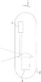
- FIG. 4 is a schematic diagram showing the relationship between the X-ray tube 1000 and the flat panel detector 101 in the projection unit 10.
- the anode AN of the X-ray tube 1000 is located on the ⁇ x side and the cathode CA is located on the + x side.
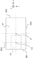
- FIGS. 5A and 5B are schematic views showing the state of the detection surface A1 of the flat detector 101 of FIG. 4 viewed from the ⁇ y side to the + y side and the relationship between the detection surface A1 and the partial detection surface A2. It is.
- the detection surface A1 has a side SD1, a side SD2, a side SD3, and a side SD4.
- the side SD1 located on the ⁇ x side is a side corresponding to the anode AN side.
- the side corresponding to the anode AN side is determined by the positional relationship between the anode AN and the cathode CA of the X-ray tube 1000 in the projection unit 10. This positional relationship may be appropriately designed according to the model of the X-ray diagnostic apparatus 1. For example, in a model in which the anode AN of the X-ray tube 1000 is located on the ⁇ z side and the cathode CA is located on the + z side, the side SD2 is a side corresponding to the anode AN side.
- the side SD3 is a side corresponding to the anode AN side.
- the side SD4 is a side corresponding to the anode AN side.
- the side SD1 is a side corresponding to the anode AN side.
- the partial detection surface A2 will be described later.
- the operation unit 2 In response to an operation by the user, the operation unit 2 inputs a signal and information corresponding to the content of the operation to each unit of the apparatus.
- the operation unit 2 includes, for example, a keyboard, a mouse, various switches, and the like.
- the display control unit 16 causes the display unit 3 to display the first image generated based on the first detection data from the projection unit 10.
- the display control unit 16 detects X-rays incident on a partial detection surface that is a partial region corresponding to the anode AN side of the detection surface A1.
- the second image generated based on the second detection data obtained in this way is enlarged and displayed on the display unit 3.
- the display control unit 16 detects, based on the enlargement size included in the enlargement instruction, and the side corresponding to the anode AN side among the sides of the detection surface A1, using at least a part of the side corresponding to the anode AN side as a side.
- the display control unit 16 includes a display data generation unit 160 and a conversion unit 161.
- the display data generation unit 160 receives image data from the image data storage unit 140, attaches desired character information or the like as incidental information to the received image data, and generates display data.
- the conversion unit 161 receives display data from the display data generation unit 160 and performs D / A conversion and television format conversion on the received display data to generate a video signal.
- the conversion unit 161 outputs the video signal to the display unit 3. Thereby, the display control unit 16 causes the display unit 3 to display an image.
- the display unit 3 receives display data from the display control unit 16 and displays it as an image.
- the display unit 3 includes a display device such as an LCD (Liquid Crystal Display) or a CRT (Cathode Ray Tube).
- the ECG measurement unit 4 measures the ECG (Electrocardiogram) of the subject E and outputs the ECG to the system control unit 15.
- the ECG measurement unit 4 is not necessarily provided as an integral part of the X-ray diagnostic apparatus 1 and may be configured to be installed outside the X-ray diagnostic apparatus 1 via a general interface.
- the mechanism unit 17 relatively moves the bed unit 12 and the projection unit 10.
- the mechanism unit 17 includes a bed unit moving mechanism 170, a C-arm rotating / moving mechanism 171, and a mechanism control unit 172.
- the bed part moving mechanism 170 moves the bed part 12 in the body axis direction of the subject E or in a direction perpendicular to the body axis.
- the C-arm rotation / movement mechanism 171 rotates the C-arm 102 in the direction around the subject E, and moves the C-arm 102 in parallel.
- the mechanism control unit 172 controls the bed unit moving mechanism 170 and the C-arm rotation / movement mechanism 171 based on the input from the system control unit 15.
- FIG. 1 A configuration for causing the X-ray diagnostic apparatus 1 to display a part of the portion of the subject depicted in the image as an enlarged image will be described.
- an image before enlarged display is set as a first image
- an image displayed in accordance with an enlargement instruction is set as a second image.
- the system control unit 15 When receiving the enlargement instruction, the system control unit 15 generates the second detection data generated based on the second detection data obtained by being incident on the partial detection surface that is a partial region corresponding to the anode AN side of the detection surface A1.
- the display control unit 16 is controlled to display the second image on the display unit 3 as an enlarged image.
- the system control unit 15 outputs the enlargement size included in the enlargement instruction and the side corresponding to the anode AN side stored in advance by the side storage unit 150 to the partial detection surface specifying unit 152.
- the enlargement instruction is input to the system control unit 15 by the user via the operation unit 2, for example.
- the system control unit 15 controls the partial detection surface specifying unit 152 to specify the partial detection surface A2.
- the center C2 of the partial detection surface A2 may be on the anode AN side with respect to the center C1 of the detection surface A1.
- the partial detection surface specifying unit 152 specifies a partial area of the detection surface A1 as a partial detection surface A2 based on at least a part of the side SD1 corresponding to the anode AN side based on the enlarged size. For example, when the enlargement size is twice the vertical and horizontal directions of the image (4 times as the area magnification), the partial detection surface A2 is half the length of the detection surface A1 in the vertical and horizontal directions. This is a region having a part of SD1 as a side (see FIG. 5A).
- the partial detection surface specifying unit 152 may specify a part of the detection surface A1 as the partial detection surface A2 with the line segment located at the distance CL from the side SD1 as the side (see FIG. 5B). In other words, the partial detection surface specifying unit 152 may specify a region having a side that is a certain distance CL away from the side SD1 as the partial detection surface A2.
- the distance CL may be preset, for example, or specified by the user.
- the position in the direction parallel to the side SD1 (z-axis coordinates in FIG. 5A or 5B) is the same between the center C1 of the detection surface A1 and the center C2 of the partial detection surface A2. In this way, the partial detection surface A2 may be specified.
- the display control unit 16 receives the partial detection surface A2 from the system control unit 15, and displays a second image generated based on the second detection data obtained by detecting the X-rays incident on the partial detection surface A2.
- the display unit 3 displays an enlarged image.
- the display control unit 16 when the display control unit 16 enlarges and displays the second image on the display unit 3, for example, the display control unit 16 reads the coordinates of the image data received from the image data generation unit 14 and is included in the partial detection surface A2 of the image data. Image data in the area may be generated as display data. The display control unit 16 outputs the display data to the display unit 3 and causes the display unit 3 to enlarge the display data as a second image.
- FIG. 6 is a schematic diagram showing the positional relationship between the first isocenter C3 and the second isocenter C4.
- the first isocenter C3 is an intersection of a straight line connecting the center C2 of the detection surface A1 and the X-ray focal point C5 and the rotation axis AX of the C arm 102.
- the second isocenter C4 is an intersection of a straight line connecting the center of the partial detection surface A2 and the X-ray focal point C5 and the rotation axis AX of the C arm 102.
- the distance between the X-ray focal point C5 and the center C1 of the detection surface A1 and the distance between the X-ray focal point C5 and the first isocenter C3 are known.
- the distance between the center C1 of the detection surface A1 and the center C2 of the partial detection surface A2 is known.
- the calculation unit 151 includes a triangle composed of the X-ray focal point C5, the center C1 of the detection surface A1, and the center C2 of the partial detection surface A2, and a triangle composed of the X-ray focal point C5, the first isocenter C3, and the second isocenter C4.
- the amount of displacement of the second isocenter C4 with respect to the first isocenter C3 is obtained based on the similarity relationship with.
- the calculation unit 151 outputs the obtained displacement amount to the system control unit 15.
- the system control unit 15 outputs a displacement instruction corresponding to the amount of displacement received from the calculation unit 151 to the mechanism unit 17. In the displacement instruction, the bed 17 and the projection unit 10 are relatively moved by controlling the mechanism unit 17 so that the position of the second isocenter C4 matches the position of the first isocenter C3 before the enlargement instruction. It is an instruction to make it.
- the mechanism unit 17 When receiving a displacement instruction from the system control unit 15, the mechanism unit 17 relatively moves the bed unit 12 and the projection unit 10 so that the position of the second isocenter C4 matches the position of the first isocenter C3.
- the mechanism control unit 172 of the mechanism unit 17 controls the C-arm rotation / movement mechanism 171 based on the received displacement instruction, and brings the position of the first isocenter C3 closer to the second isocenter C4.
- the projection unit 10 in the direction, that is, the direction from the second isocenter C4 to the first isocenter C3, the position of the second isocenter C4 is matched with the position of the first isocenter C3.
- the matching accuracy at this time is a design matter of the X-ray diagnostic apparatus 1 and may be designed within an error range that can be practically used.
- the mechanism control unit 172 controls the couch unit moving mechanism 170 to bring the position of the first isocenter C3 closer to the second isocenter C4, that is, from the first isocenter C3 to the second isocenter C4.
- the position of the second isocenter C4 may be matched with the position of the first isocenter C3 by moving the bed portion 12 in the direction of.
- the mechanism control unit 172 controls both the C-arm rotation / movement mechanism 171 and the bed part movement mechanism 170, and moves both the projection part 10 and the bed part 12 to thereby move the second isocenter C4. May be matched with the position of the first isocenter C3. Thereby, the center of the first image and the center of the second image coincide with each other, and the desired portion is enlarged and displayed on the display unit 3.
- the system control unit 15 controls the X-ray diaphragm unit 1001 based on the enlargement size included in the enlargement instruction and the side corresponding to the anode AN side, so that the X is applied to the partial detection surface A2.
- a slit for irradiating a line may be formed. At this time, the size of the slit is reduced before receiving the enlargement instruction, and the position of the slit is biased toward the side corresponding to the anode AN side.
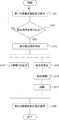
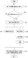
- FIG. 7 is a flowchart showing the operation of the X-ray diagnostic apparatus 1.
- Step S01 The X-ray diagnostic apparatus 1 captures the first image and displays it on the display unit 3.
- the X-ray generator 100 irradiates the detection surface A1 with X-rays, and the flat detector 101 detects the X-rays that have passed through the subject E and entered the detection surface A1.
- the flat detector 101 outputs the first detection data to the projection data generation unit 131.
- the projection data generation unit 131 outputs projection data based on the received first detection data to the image data generation unit 14.
- the image data generation unit 14 generates image data based on the received projection data and outputs it to the display control unit 16.
- the display control unit 16 generates display data based on the received image data and causes the display unit 3 to display the display data.
- Steps S02 and S03 When receiving an enlargement instruction (YES in step S02), the system control unit 15 specifies the partial detection surface by specifying the enlargement size included in the enlargement instruction and the side corresponding to the anode AN stored in the side storage unit 150. Output to the unit 152. The partial detection surface specifying unit 152 outputs the specified partial detection surface A2 to the X-ray diaphragm unit 1001 and the calculation unit 151.
- the system control unit 15 has not received an enlargement instruction (NO in step S02)
- the operation of the X-ray diagnostic apparatus 1 returns to step S01.
- Step S04 X-ray diaphragm unit 1001 changes the slit based on partial detection surface A ⁇ b> 2 received from partial detection surface specifying unit 152. Thereby, X-rays from the X-ray tube 1000 are irradiated toward the partial detection surface A2.
- Step S05 Based on the detection surface A1 and the partial detection surface A2 received from the partial detection surface specifying unit 152, the calculation unit 151 calculates the second isocenter corresponding to the partial detection surface A2 with respect to the first isocenter C3 corresponding to the detection surface A1. The amount of displacement of C4 is obtained. The calculation unit 151 outputs the obtained displacement amount to the system control unit 15. The system control unit 15 outputs a displacement instruction corresponding to the amount of displacement received from the calculation unit 151 to the mechanism unit 17.
- Step S06 The mechanism unit 17 receives a displacement instruction from the system control unit 15 and relatively moves the bed unit 12 and the projection unit 10 so that the position of the second isocenter C4 matches the position of the first isocenter C3.
- Step S04, step S05, and step S06 correspond to a parallel processing relationship.
- Step S07 The X-ray diagnostic apparatus 1 captures the second image and displays it on the display unit 3.
- the X-ray generation unit 100 irradiates the partial detection surface A2 with X-rays
- the flat detector 101 detects the X-rays that have passed through the subject E and entered the partial detection surface A2.
- the flat detector 101 outputs the second detection data to the projection data generation unit 131.
- the projection data generation unit 131 outputs projection data based on the received second detection data to the image data generation unit 14.
- the image data generation unit 14 generates image data based on the received projection data and outputs it to the display control unit 16.
- the display control unit 16 generates display data based on the received image data, and displays the display data on the display unit 3 in an enlarged manner. This completes the operation shown in FIG.
- the X-ray diagnostic apparatus 1 includes a bed unit 12 on which the subject E is placed, a projection unit 10, a display control unit 16, and a system control unit 15.
- the projection unit 10 detects an X-ray tube 1000 having an anode AN that receives the cathode CA and electrons from the cathode CA and irradiates the subject E with X-rays, and X-rays that pass through the subject E and enter the detection surface A1.
- a first detector causes the display unit 3 to display the first image generated based on the first detection data from the projection unit 10.
- the system control unit 15 is a partial region corresponding to the anode AN side of the detection surface A1 when receiving an enlargement instruction to display a part of the portion of the subject E depicted in the first image as an enlarged image.
- the display control unit 16 is controlled so that the second image generated based on the second detection data obtained by detecting the X-rays incident on the partial detection surface A2 is displayed on the display unit 3 as an enlarged image.
- the X-ray diagnostic apparatus 1 enlarges and displays an image based on the X-rays incident on the partial detection surface A2.
- X-rays on the anode AN side of the X-ray tube 1000 are incident on the partial detection surface A2, and an image based on the X-rays on the anode AN side has good resolution. Accordingly, it is possible to provide the X-ray diagnostic apparatus 1 that can improve the resolution of the enlarged image.
- the system control unit 15 has a calculation unit 151.
- the calculation unit 151 calculates the second isocenter C4 corresponding to the partial detection surface A2 corresponding to the first isocenter C3 corresponding to the detection surface A1.
- the displacement amount is obtained and the obtained displacement amount is output to the system control unit 15.
- the system control unit 15 outputs a displacement instruction corresponding to the amount of displacement received from the calculation unit 151 to the mechanism unit 17. Further, when the mechanism unit 17 receives a displacement instruction from the system control unit 15, the mechanism unit 17 moves the bed unit 12 and the projection unit 10 relative to each other so that the position of the second isocenter C4 matches the position of the first isocenter C3. Move to.
- the X-ray diagnostic apparatus 1 that can improve the resolution of the enlarged image and can display the enlarged image while displaying the same part.
- the system control unit 15 When receiving an enlargement instruction, the system control unit 15 connects the center C2 of the partial detection surface A2 and the X-ray focal point C5 to the first straight line connecting the center C1 of the detection surface A1 and the X-ray focal point C5.
- a rotation instruction representing a rotational movement in which the straight lines are parallel is output to the mechanism unit 17.
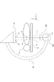
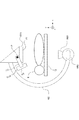
- FIG. 8A is a schematic diagram showing the bed unit 12, the subject E, and the projection unit 10 before the mechanism unit 17 moves the bed unit 12 and the projection unit 10 relatively.
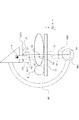
- FIG. 8B is a schematic diagram illustrating the bed unit 12, the subject E, and the projection unit 10 when the mechanism unit 17 relatively moves the bed unit 12 and the projection unit 10.
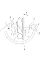
- FIG. 8C is a schematic diagram illustrating the bed unit 12, the subject E, and the projection unit 10 when the mechanism unit 17 relatively rotates the bed unit 12 and the projection unit 10.
- the direction of the first straight line L1 corresponds to the X-ray irradiation direction to the subject E before the enlargement instruction.
- the second straight line L2 direction corresponds to the X-ray irradiation direction to the subject E after the enlargement instruction.
- the system control unit 15 obtains the angle between the direction of the first straight line L1 and the direction of the second straight line L2 based on the amount of displacement calculated by the calculation unit 151.
- the system control unit 15 instructs to relatively rotate the bed unit 12 and the projection unit 10 based on the obtained angle, that is, rotational movement in which the first straight line L1 and the second straight line L2 are parallel to each other. Is output to the mechanism unit 17.
- the mechanism unit 17 When receiving the rotation instruction, the mechanism unit 17 relatively rotates the bed unit 12 and the projection unit 10. At this time, the mechanism control unit 172 of the mechanism unit 17 controls the C-arm rotation / movement mechanism 171 based on the received rotation instruction, and rotates the projection unit 10 to thereby generate the second straight line L2. It is made parallel to the first straight line L1.
- the parallel accuracy at this time is a design matter of the X-ray diagnostic apparatus, and may be designed within a range of errors that can withstand practical use.
- the mechanism control unit 172 may control the bed part moving mechanism 170 and rotate the bed part 12 to make the second straight line L2 parallel to the first straight line L1.
- the mechanism control unit 172 controls both the C-arm rotation / movement mechanism 171 and the bed part movement mechanism 170, and rotates both the projection part 10 and the bed part 12 to thereby generate the second straight line.
- L2 may be parallel to the first straight line L1.
- the mechanism unit 17 may rotate about the isocenter C30 after the bed unit 12 and the projection unit 10 are relatively moved. In this case, a shift occurs between the position of the first isocenter C3 before the enlargement instruction and the position of the second isocenter C4 after the rotation.
- the isocenter C30 is an isocenter on a straight line connecting the X-ray focal point C5 after the bed unit 12 and the projection unit 10 are relatively moved and the center C10 of the detection surface A1 of the flat detector 101.
- the calculation unit 151 obtains the length and direction of the shift based on the position of the first isocenter C3 before the enlargement instruction, the position of the isocenter C30, and the rotation angle of the projection unit 10, and the obtained length. And the direction are output to the system control unit 15.
- the system control unit 15 outputs a displacement instruction based on the length obtained by the calculation unit 151 to the control unit 17.
- the mechanism unit 17 relatively moves the bed unit 12 and the projection unit 10 based on the displacement instruction. As a result, even in this case, the second isocenter matches the position of the first isocenter C3 before the enlargement instruction.
- FIG. 9 is a flowchart showing the operation of the X-ray diagnostic apparatus of this embodiment.
- Step S11 to Step S16 The processing from step S11 to step S16 corresponds to the processing from step S01 to step S06 in the flowchart of FIG.
- Step S17 The system control unit 15 makes the second straight line L2 connecting the center C2 of the partial detection surface A2 and the X-ray focal point C5 parallel to the first straight line L1 connecting the center C1 of the detection surface A1 and the X-ray focal point C5.
- a rotation instruction representing the rotational movement is output to the mechanism unit 17.
- the mechanism unit 17 receives the rotation instruction, and relatively rotates the bed unit 12 and the projection unit 10 to make the second straight line L2 parallel to the first straight line L1.
- Step S18 The process of step S18 corresponds to the process of step S07 in the flowchart of FIG.
- FIG. 10 is a block diagram showing the configuration of the X-ray diagnostic apparatus 1 according to this embodiment.
- FIG. 11A and FIG. 11B are schematic views showing an outline of the projection unit 10 of this embodiment.
- the projection unit 10 includes a first detector 1011 and a second detector 1012.
- the first detector 1011 corresponds to the flat detector 101 in the first embodiment.
- the mechanism unit 17 includes a second detector insertion / extraction mechanism 173.
- the second detector 1012 is configured to be insertable between the first detector 1011 and the subject E.
- the second detector 1012 is inserted and removed between the first detector 1011 and the subject E by the second detector insertion / extraction mechanism 173.
- FIG. 11A schematically shows a state before the second detector 1012 is inserted between the first detector 1011 and the subject E.
- FIG. 11B schematically shows a state in which the second detector 1012 is inserted between the first detector 1011 and the subject E.
- the second detector insertion / extraction mechanism 173 is formed in an arm shape. One end of the second detector insertion / extraction mechanism 173 is rotatably attached to a predetermined position P above the first detector 1011 (in the + y direction in FIGS.
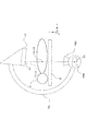
- FIG. 12A is a schematic diagram illustrating the bed part 12, the subject E, and the projection part 10 before the mechanism part 17 relatively moves the bed part 12 and the projection part 10.
- FIG. 12B is a schematic diagram illustrating the bed unit 12, the subject E, and the projection unit 10 when the mechanism unit 17 relatively moves the bed unit 12 and the projection unit 10.
- FIG. 12C is a schematic diagram illustrating the bed unit 12, the subject E, and the projection unit 10 when the mechanism unit 17 relatively rotates the bed unit 12 and the projection unit 10. Details will be described later.
- the second detector 1012 a flat detector having a higher spatial resolution for X-ray detection than that of the first detector 1011 is used. At this time, the image based on the X-ray detected by the second detector 1012 has a higher resolution than the image based on the X-ray detected by the first detector 1011.
- an indirect conversion type flat detector is used as the first detector 1011
- a direct conversion type flat detector is used as the second detector 1012.
- the system control unit 15 When the system control unit 15 receives an insertion instruction for inserting the second second detector 1012, the system control unit 15 moves the second isolator C 1 to the position of the first isocenter C 1 corresponding to the detection surface A 1 of the first detector 1011.
- a displacement instruction indicating the direction in which the third isocenter C6 corresponding to the detection surface A3 of the detector 1012 is brought closer is output to the mechanism unit 17.
- the partial detection surface A2, the center C2 of the partial detection surface A2, and the second isocenter C4 in the first embodiment are the same as the detection surface A3 of the second detector 1012 in the third embodiment. This corresponds to the replacement with the center C7 of the detection surface A3 of the second detector 1012 and the third isocenter C6.
- the position information of the detection surface A3 is specified based on the control information of the second detector insertion / extraction mechanism 173.
- the insertion instruction is input to the system control unit 15 by the user via the operation unit.
- the system control unit 15 When the system control unit 15 receives an insertion instruction for inserting the second detector 1012, the first straight line L 1 connecting the center C 1 of the detection surface A 1 of the first detector 1011 and the X-ray focal point C 5.
- a rotation instruction indicating a rotational movement in which the third straight line L3 connecting the center C6 of the detection surface A3 of the second detector 1012 and the X-ray focal point C5 is parallel may be output to the mechanism unit 17. This corresponds to the replacement of the second straight line L2 in the second embodiment with the third straight line L3 in the third embodiment.
- the mechanism part 17 moves the bed part 12 and the projection part 10 relatively when receiving the displacement instruction.
- the partial detection surface A2, the center C2 of the partial detection surface A2, and the second isocenter C4 in the first embodiment are the same as the detection surface A3 of the second detector 1012 in the third embodiment. This corresponds to the replacement with the center C7 of the detection surface A3 of the second detector 1012 and the third isocenter C6.
- mechanism part 17 rotates the bed part 12 and the projection part 10 relatively, when the rotation instruction
- FIG. 12A is a schematic diagram showing the bed unit 12, the subject E, and the projection unit 10 before the mechanism unit 17 moves the bed unit 12 and the projection unit 10 relatively.
- FIG. 12B is a schematic diagram illustrating the bed unit 12, the subject E, and the projection unit 10 when the mechanism unit 17 relatively moves the bed unit 12 and the projection unit 10.
- FIG. 12C is a schematic diagram showing the bed unit 12, the subject E, and the projection unit 10 when the mechanism unit 17 relatively rotates the bed unit 12 and the projection unit 10.
- the user visually recognizes an image based on the first detector 1011 during fluoroscopy, and then enlarges the image based on the second detector 1012 whose resolution is higher than that of the second detector 1012. You may want to see as.
- the X-ray diagnostic apparatus 1 interlocks with the insertion instruction for inserting the second detector 1012 to match the isocenter after the insertion instruction with the position of the isocenter before the insertion instruction.
- the X-ray irradiation direction with respect to the subject E and the X-ray irradiation direction after the insertion instruction can be made parallel.
- the X-ray diagnostic apparatus 1 When an enlargement instruction for an image based on the X-rays detected by the second detector 1012 is given, the X-ray diagnostic apparatus 1 replaces the flat detector 101 in the first embodiment with the second detector 1012. An enlarged image may be displayed depending on the configuration.
- FIG. 13 is a flowchart showing the operation of the X-ray diagnostic apparatus 1 of this embodiment.
- Step S21 The X-ray diagnostic apparatus 1 captures the first image and displays it on the display unit 3.
- the X-ray generation unit 100 irradiates the detection surface A1 with X-rays, and the first detector 1011 detects X-rays that have passed through the subject E and entered the detection surface A1.
- the first detector 1011 outputs the first detection data to the projection data generation unit 131.
- the projection data generation unit 131 outputs projection data based on the received first detection data to the image data generation unit 14.
- the image data generation unit 14 generates image data based on the received projection data and outputs it to the display control unit 16.
- the display control unit 16 generates display data based on the received image data and causes the display unit 3 to display the display data.
- Steps S22 and S23 When receiving an insertion instruction (YES in step S22), the system control unit 15 controls the mechanism 17 to insert the second detector 1012 between the first detector 1011 and the subject E. When the system control unit 15 has not received an insertion instruction (NO in step S22), the operation of the X-ray diagnostic apparatus 1 returns to step S21.
- Step S24 The X-ray diaphragm unit 1001 changes the slit based on the detection surface A3 of the second detector 1012. Thereby, X-rays from the X-ray tube 1000 are irradiated toward the detection surface A3.
- Step S25 Based on the detection surface A1 and the detection surface A3, the calculation unit 151 obtains a displacement amount of the third isocenter C6 corresponding to the detection surface A3 with respect to the first isocenter C3 corresponding to the detection surface A1. The calculation unit 151 outputs the obtained displacement amount to the system control unit 15. The system control unit 15 outputs a displacement instruction corresponding to the amount of displacement received from the calculation unit 151 to the mechanism unit 17.
- Step S26 The mechanism unit 17 receives a displacement instruction from the system control unit 15 and relatively moves the bed unit 12 and the projection unit 10 so that the position of the third isocenter C6 matches the position of the first isocenter C3.
- Step S24, step S25, and step S26 correspond to a parallel processing relationship.
- Step S27 The system control unit 15 makes the third straight line L3 connecting the center C7 of the detection surface A3 and the X-ray focal point C5 parallel to the first straight line L1 connecting the center C1 of the detection surface A1 and the X-ray focal point C5.
- a rotation instruction representing the rotational movement is output to the mechanism unit 17.
- the mechanism unit 17 receives the rotation instruction, and relatively rotates the bed unit 12 and the projection unit 10 to make the third straight line L3 parallel to the first straight line L1.
- Step S28 The X-ray diagnostic apparatus 1 captures an image based on the X-ray detected by the second detector 1012 and displays the image on the display unit 3.
- the X-ray generation unit 100 irradiates the detection surface A3 with X-rays
- the second detector 1012 detects X-rays that have passed through the subject E and entered the detection surface A3.
- the second detector 1012 outputs detection data to the projection data generation unit 131.
- the projection data generation unit 131 outputs projection data based on the received detection data to the image data generation unit 14.
- the image data generation unit 14 generates image data based on the received projection data and outputs it to the display control unit 16.
- the display control unit 16 generates display data based on the received image data, and displays the display data on the display unit 3 in an enlarged manner. This completes the operation shown in FIG.
- the projection unit 10 includes a first detector 1011 and a second detector 1012.
- the system control unit 15 receives an insertion instruction for inserting the second second detector 1012, the system control unit 15 moves the second isolator C 1 to the position of the first isocenter C 1 corresponding to the detection surface A 1 of the first detector 1011.
- a displacement instruction indicating the direction in which the third isocenter C6 corresponding to the detection surface A3 of the detector 1012 is brought closer is output to the mechanism unit 17.
- the system control unit 15 When the system control unit 15 receives an insertion instruction for inserting the second detector 1012, the first straight line L 1 connecting the center C 1 of the detection surface A 1 of the first detector 1011 and the X-ray focal point C 5.
- a rotation instruction representing a rotational movement in which the third straight line L3 connecting the center C6 of the detection surface A3 of the second detector 1012 and the X-ray focal point C5 is parallel is output to the mechanism unit 17.
- the mechanism unit 17 When the mechanism unit 17 receives the displacement instruction, the mechanism unit 17 relatively moves the bed unit 12 and the projection unit 10. In addition, the mechanism part 17 rotates the bed part 12 and the projection part 10 relatively, when the rotation instruction
- the X-ray diagnostic apparatus 1 makes the isocenter after the insertion instruction coincide with the position of the isocenter before the insertion instruction in conjunction with the insertion instruction to insert the second detector 1012, and the subject E before the insertion instruction.
- the X-ray irradiation direction with respect to the X-ray irradiation direction after the insertion instruction can be made parallel. Therefore, it is possible to provide an X-ray diagnostic apparatus in which the position of the isocenter is matched between the image before and after the second detector is inserted, and the X-ray irradiation direction on the subject can be made parallel. Can do.
Landscapes
- Life Sciences & Earth Sciences (AREA)
- Health & Medical Sciences (AREA)
- Engineering & Computer Science (AREA)
- Medical Informatics (AREA)
- Pathology (AREA)
- Heart & Thoracic Surgery (AREA)
- High Energy & Nuclear Physics (AREA)
- Physics & Mathematics (AREA)
- Nuclear Medicine, Radiotherapy & Molecular Imaging (AREA)
- Optics & Photonics (AREA)
- Veterinary Medicine (AREA)
- Radiology & Medical Imaging (AREA)
- Biomedical Technology (AREA)
- Biophysics (AREA)
- Molecular Biology (AREA)
- Surgery (AREA)
- Animal Behavior & Ethology (AREA)
- General Health & Medical Sciences (AREA)
- Public Health (AREA)
- Human Computer Interaction (AREA)
- Apparatus For Radiation Diagnosis (AREA)
Abstract
拡大表示された画像の解像度を向上することができるX線撮影装置を提供すること。 X線診断装置は、被検体が載置される寝台部と、投影部と、表示制御部と、システム制御部とを有する。投影部は、陰極及び陰極からの電子を受けて被検体にX線を照射する陽極を備えるX線管と被検体を透過し検出面に入射したX線を検出する第1の検出器とを含む。表示制御部は、投影部による第1の検出データに基づいて生成された第1の画像を表示部に表示させる。システム制御部は、第1の画像に描出された被検体の部位の一部を拡大画像として表示させる拡大指示を受けたとき、検出面のうち陽極側に相当する部分領域である部分検出面に入射したX線を検出して得られた第2の検出データに基づいて生成された第2の画像を拡大画像として表示部に表示させるように表示制御部を制御する。
Description
本発明の実施形態はX線診断装置に関する。
X線診断装置は、被検体にX線を照射して、その透過X線を検出し被検体内部の構造を画像化するものである。
従来、C字形状の支持器(Cアーム)、支持器の一端に備えられたX線管、支持器の他端に備えられた平面検出器、被検体が載置される寝台、収集された投影データを処理する画像処理装置等からなるX線診断装置が知られている。
このようなX線診断装置は、被検体へのカテーテルの挿入作業等の医師による手術又は検査(診断)とともに、これに並行したX線撮影を行う。このとき、医師は撮影された画像を視認することによって被検体の内部構造を把握しながら手術又は検査を行う。
このとき、X線診断装置は画像を拡大表示させる指示を受ける場合がある。この場合、X線診断装置は、受けた指示の拡大サイズを平面検出器の検出面における領域に変換し、この変換された領域を、検出面における視野中心を固定するように平面検出器に割り当てる。そして、X線診断装置は割り当てられた領域に入射したX線に基づいて生成された画像を表示する。
また、X線管は陰極及び陽極を備える。陽極は、陰極からの電子を受けてX線を発生し、被検体にX線を照射する。照射されるX線は、広がり角を有する。
平面検出器は、被検体を透過し検出面に入射したX線を検出する。X線診断装置は、入射したX線に基づく画像を生成し表示する。この画像のうち、広がり角の陽極側のX線が入射した投影データに基づく画像は、広がり角の陰極側のX線が入射した投影データに基づく画像よりも解像度が良いことが知られている。換言すると、画像の解像度は、陽極側から陰極側に亘って下がることが知られている。
従来のX線診断装置は、平面検出器の検出面における視野中心を固定するように画像を拡大表示させていた。それにより、拡大前の画像において解像度が下がっている部分が拡大表示されていた。従って、医師は解像度がよくない拡大画像を視認しなければならず、医師による拡大画像の視認性が下がるという問題があった。画像の視認性が下がると、手術又は検査時間の長時間化や、その長時間化による被検体の被ばく量の増加などの懸念が生じた。
本発明が解決しようとする課題は、拡大表示された画像の解像度を向上することができるX線診断装置を提供することである。
実施形態に係るX線診断装置は、被検体が載置される寝台部と、投影部と、表示制御部と、システム制御部とを有する。投影部は、陰極及び陰極からの電子を受けて被検体にX線を照射する陽極を備えるX線管と被検体を透過し検出面に入射したX線を検出する第1の検出器とを含む。表示制御部は、投影部による第1の検出データに基づいて生成された第1の画像を表示部に表示させる。システム制御部は、第1の画像に描出された被検体の部位の一部を拡大画像として表示させる拡大指示を受けたとき、検出面のうち陽極側に相当する部分領域である部分検出面に入射したX線を検出して得られた第2の検出データに基づいて生成された第2の画像を拡大画像として表示部に表示させるように表示制御部を制御する。
〈第1の実施形態〉
図面を参照してこの実施形態のX線診断装置について説明する。
図面を参照してこの実施形態のX線診断装置について説明する。
[基本構成]
図1は、この実施形態のX線診断装置1の構成を表すブロック図である。また、図2は、X線診断装置1の外観を表す模式図である。X線診断装置1は、投影部10と、高電圧発生部11と、寝台部12と、X線検出部13と、画像データ生成部14と、システム制御部15と、操作部2と、表示制御部16と、表示部3と、ECG計測部4と、機構部17とを有する。
図1は、この実施形態のX線診断装置1の構成を表すブロック図である。また、図2は、X線診断装置1の外観を表す模式図である。X線診断装置1は、投影部10と、高電圧発生部11と、寝台部12と、X線検出部13と、画像データ生成部14と、システム制御部15と、操作部2と、表示制御部16と、表示部3と、ECG計測部4と、機構部17とを有する。
(投影部10)
投影部10は、X線発生部100と、平面検出器101と、Cアーム102とを有する。X線発生部100は、被検体EにX線を照射する。X線発生部100は、X線管1000とX線絞り部1001とを有する。X線管1000は、X線を発生する真空管である。図3は、X線管1000の概略を表す模式図である。X線管1000は、陰極CAと陽極ANとを備える。陰極CAは、電子を放出する。陽極ANは、陰極CAからの電子を受けてX線を発生し、被検体EにX線を照射する。ここで、x軸の負側を陽極AN側とし、x軸の正側を陰極CA側とする。前述したように、陽極AN側のX線に基づく画像は陰極CA側のX線に基づく画像よりも解像度が良い。X線絞り部1001は、X線管1000と被検体Eとの間に位置する。X線絞り部1001は、スリット(開口)を形成し、このスリットのサイズ及び形状を変えることで、X線管1000が発生させたX線の照射視野を調整する。
投影部10は、X線発生部100と、平面検出器101と、Cアーム102とを有する。X線発生部100は、被検体EにX線を照射する。X線発生部100は、X線管1000とX線絞り部1001とを有する。X線管1000は、X線を発生する真空管である。図3は、X線管1000の概略を表す模式図である。X線管1000は、陰極CAと陽極ANとを備える。陰極CAは、電子を放出する。陽極ANは、陰極CAからの電子を受けてX線を発生し、被検体EにX線を照射する。ここで、x軸の負側を陽極AN側とし、x軸の正側を陰極CA側とする。前述したように、陽極AN側のX線に基づく画像は陰極CA側のX線に基づく画像よりも解像度が良い。X線絞り部1001は、X線管1000と被検体Eとの間に位置する。X線絞り部1001は、スリット(開口)を形成し、このスリットのサイズ及び形状を変えることで、X線管1000が発生させたX線の照射視野を調整する。
平面検出器101は、被検体Eを透過し検出面に入射したX線を検出する。例えば、平面検出器101は、検出面に入射したX線を電荷に変換して蓄積する。平面検出器101は、検出面に複数のX線検出素子が2次元的に配置されて構成される。X線検出素子は、光電膜と、電荷蓄積コンデンサと、薄膜トランジスタとを備える。光電膜は、X線を感知し、感知したX線の線量に応じて電荷を生成する。電荷蓄積コンデンサは、光電膜が生成した電荷を蓄積する。薄膜トランジスタは、電荷蓄積コンデンサに蓄積された電荷を読み出す。平面検出器101は、薄膜トランジスタが読み出した電荷を検出データとして電荷・電圧変換部1310へ出力する。なお、平面検出器101は、本発明における「第1の検出器」の一例に相当する。
Cアーム102は、X線発生部100と平面検出器101とを支持する。Cアーム102は、C字形状であり、一端にX線管1000を備え、他端に平面検出器101を備える。
(高電圧発生部11)
高電圧発生部11は、X線発生部100がX線を照射するための高電圧を発生する。高電圧発生部11は、X線制御部110と高電圧発生器111とを有する。X線制御部110は、システム制御部15からの入力に基づいて、X線管1000における管電流、管電圧、照射時間等のX線照射条件についての制御信号を高電圧発生器111へ出力する。高電圧発生器111は、X線制御部110からの入力に基づいて、X線管1000の陽極ANと陰極CAとの間に高電圧を印加する。
高電圧発生部11は、X線発生部100がX線を照射するための高電圧を発生する。高電圧発生部11は、X線制御部110と高電圧発生器111とを有する。X線制御部110は、システム制御部15からの入力に基づいて、X線管1000における管電流、管電圧、照射時間等のX線照射条件についての制御信号を高電圧発生器111へ出力する。高電圧発生器111は、X線制御部110からの入力に基づいて、X線管1000の陽極ANと陰極CAとの間に高電圧を印加する。
(寝台部12)
寝台部12には被検体Eが載置される。寝台部12は、寝台部移動機構170からの入力に基づいて、載置された被検体Eをその体軸方向や上下方向に移動させる。
寝台部12には被検体Eが載置される。寝台部12は、寝台部移動機構170からの入力に基づいて、載置された被検体Eをその体軸方向や上下方向に移動させる。
(X線検出部13)
X線検出部13は、ゲートドライバ130と投影データ生成部131とを有する。ゲートドライバ130は、薄膜トランジスタが電荷蓄積コンデンサに蓄積された電荷を読み出すために、薄膜トランジスタのゲート端子へ読み出し用の駆動パルスを出力する。
X線検出部13は、ゲートドライバ130と投影データ生成部131とを有する。ゲートドライバ130は、薄膜トランジスタが電荷蓄積コンデンサに蓄積された電荷を読み出すために、薄膜トランジスタのゲート端子へ読み出し用の駆動パルスを出力する。
投影データ生成部131は、平面検出器101からの検出データに基づいて投影データを生成する。投影データ生成部131は、電荷・電圧変換部1310とA/D変換部1311とを有する。電荷・電圧変換部1310は、平面検出器101から検出データとして受けた電荷を電圧に変換し、変換した電圧の信号をA/D変換部1311に出力する。A/D変換部1311は、電荷・電圧変換部1310からの信号を受け、デジタル信号に変換する。A/D変換部1311は、変換したデジタル信号を画像データ記憶部140へ出力する。
(画像データ生成部14)
画像データ生成部14は、投影データ生成部131による投影データに基づいて、被検体E内部の構造を表す画像データを生成及び記憶する。画像データ生成部14は、画像データ記憶部140と画像演算部141とを有する。画像データ記憶部140は、投影データ生成部131による投影データと画像演算部141による画像データとを記憶する。画像データ記憶部140は、投影データを画像演算部141へ出力する。画像データ記憶部140は、画像データを表示データ生成部160へ出力する。
画像データ生成部14は、投影データ生成部131による投影データに基づいて、被検体E内部の構造を表す画像データを生成及び記憶する。画像データ生成部14は、画像データ記憶部140と画像演算部141とを有する。画像データ記憶部140は、投影データ生成部131による投影データと画像演算部141による画像データとを記憶する。画像データ記憶部140は、投影データを画像演算部141へ出力する。画像データ記憶部140は、画像データを表示データ生成部160へ出力する。
画像演算部141は、画像データ記憶部140による投影データを受け、投影データに種々の画像処理を行って被検体E内部の構造を表す画像データを生成する。画像演算部141は、生成した画像データを画像データ記憶部140へ出力する。
(システム制御部15)
システム制御部15は、操作部2から入力されるユーザによるコマンド信号や撮影条件などの情報を一旦記憶した後、これらの情報に基づいたX線投影データの生成、画像データの生成と表示、機構部17についての制御など各部の制御を行う。システム制御部15は、たとえば処理装置と記憶装置を含んで構成される。処理装置としては、たとえば、CPU(Central Processing Unit)、GPU(Graphic Processing Unit)、又はASIC(Application Specific Integrated Circuit)が用いられる。記憶装置は、たとえば、ROM(Read Only Memory)、RAM(Random Access Memory)、HDD(Hard Disc Drive)を含んで構成される。記憶装置には、X線診断装置1の各部の機能を実行するためのコンピュータプログラムが記憶されている。処理装置は、これらコンピュータプログラムを実行することで、上記機能を実現する。
システム制御部15は、操作部2から入力されるユーザによるコマンド信号や撮影条件などの情報を一旦記憶した後、これらの情報に基づいたX線投影データの生成、画像データの生成と表示、機構部17についての制御など各部の制御を行う。システム制御部15は、たとえば処理装置と記憶装置を含んで構成される。処理装置としては、たとえば、CPU(Central Processing Unit)、GPU(Graphic Processing Unit)、又はASIC(Application Specific Integrated Circuit)が用いられる。記憶装置は、たとえば、ROM(Read Only Memory)、RAM(Random Access Memory)、HDD(Hard Disc Drive)を含んで構成される。記憶装置には、X線診断装置1の各部の機能を実行するためのコンピュータプログラムが記憶されている。処理装置は、これらコンピュータプログラムを実行することで、上記機能を実現する。
システム制御部15は、辺記憶部150と算出部151と部分検出面特定部152とを有する。辺記憶部150は、平面検出器101の検出面の辺のうちX線管1000の陽極AN側に相当する辺を予め記憶する。この辺は、後述する部分検出面の基準となる。図4は、投影部10におけるX線管1000と平面検出器101との関係を表す模式図である。この形態では、X線管1000の陽極ANが-x側、陰極CAが+x側に位置する。すなわち、-x側のX線に基づく画像は+x側のX線に基づく画像よりも解像度が良い。また、図5A及び図5Bは、図4の平面検出器101の検出面A1を-y側から+y側の方向へ見た様子と、検出面A1及び部分検出面A2の関係とを表す模式図である。検出面A1は辺SD1、辺SD2、辺SD3、辺SD4を有する。この形態では、-x側に位置する辺SD1が陽極AN側に相当する辺である。陽極AN側に相当する辺は、投影部10におけるX線管1000の陽極ANと陰極CAとの位置関係によって定まる。この位置関係は、X線診断装置1の機種によって適宜設計してよい。例えば、X線管1000の陽極ANが-z側、陰極CAが+z側に位置する機種において、辺SD2が陽極AN側に相当する辺である。同様に、X線管1000の陽極ANが+x側、陰極CAが-x側に位置する機種において、辺SD3が陽極AN側に相当する辺である。また、X線管1000の陽極ANが+z側、陰極CAが-z側に位置する機種において、辺SD4が陽極AN側に相当する辺である。この実施形態では、辺SD1が陽極AN側に相当する辺である例について説明する。また、部分検出面A2については後述する。
(操作部2)
操作部2は、ユーザによる操作を受けて、この操作の内容に応じた信号や情報を装置各部に入力する。操作部2は、たとえばキーボード、マウス、各種スイッチ等により構成される。
操作部2は、ユーザによる操作を受けて、この操作の内容に応じた信号や情報を装置各部に入力する。操作部2は、たとえばキーボード、マウス、各種スイッチ等により構成される。
(表示制御部16)
表示制御部16は、投影部10による第1の検出データに基づいて生成された第1の画像を表示部3に表示させる。表示制御部16は、第1の画像の一部を拡大表示させる拡大指示を受けたとき、検出面A1のうち陽極AN側に相当する部分領域である部分検出面に入射したX線を検出して得られた第2の検出データに基づいて生成された第2の画像を表示部3に拡大表示させる。例えば、表示制御部16は、拡大指示に含まれる拡大サイズと検出面A1の辺のうち陽極AN側に相当する辺とに基づいて、陽極AN側に相当する辺の少なくとも一部を辺とし検出面A1の部分領域である部分検出面A2に入射したX線を検出して得られた第2の検出データに基づいて生成された第2の画像を表示部3に拡大表示させる。
表示制御部16は、投影部10による第1の検出データに基づいて生成された第1の画像を表示部3に表示させる。表示制御部16は、第1の画像の一部を拡大表示させる拡大指示を受けたとき、検出面A1のうち陽極AN側に相当する部分領域である部分検出面に入射したX線を検出して得られた第2の検出データに基づいて生成された第2の画像を表示部3に拡大表示させる。例えば、表示制御部16は、拡大指示に含まれる拡大サイズと検出面A1の辺のうち陽極AN側に相当する辺とに基づいて、陽極AN側に相当する辺の少なくとも一部を辺とし検出面A1の部分領域である部分検出面A2に入射したX線を検出して得られた第2の検出データに基づいて生成された第2の画像を表示部3に拡大表示させる。
表示制御部16は、表示データ生成部160と変換部161とを有する。表示データ生成部160は、画像データ記憶部140から画像データを受け、受けた画像データに所望の文字情報等を付帯情報として付帯し、表示データを生成する。変換部161は、表示データ生成部160から表示データを受け、受けた表示データにD/A変換とテレビフォーマット変換とを行って映像信号を生成する。変換部161は、映像信号を表示部3へ出力する。それにより、表示制御部16は画像を表示部3に表示させる。
(表示部3)
表示部3は、表示制御部16から表示データを受け、画像として表示する。表示部3は、例えば、LCD(Liquid Crystal Display)、CRT(Cathode Ray Tube)等の表示デバイスによって構成される。
表示部3は、表示制御部16から表示データを受け、画像として表示する。表示部3は、例えば、LCD(Liquid Crystal Display)、CRT(Cathode Ray Tube)等の表示デバイスによって構成される。
(ECG計測部4)
ECG計測部4は、被検体EのECG(Electrocardiogram:心電図)を測定し、そのECGをシステム制御部15に出力する。なお、ECG計測部4は、必ずしもX線診断装置1の一体として備えられる必要はなく、一般的なインターフェイスを介してX線診断装置1の外部に設置される構成でもよい。
ECG計測部4は、被検体EのECG(Electrocardiogram:心電図)を測定し、そのECGをシステム制御部15に出力する。なお、ECG計測部4は、必ずしもX線診断装置1の一体として備えられる必要はなく、一般的なインターフェイスを介してX線診断装置1の外部に設置される構成でもよい。
(機構部17)
機構部17は、寝台部12と投影部10とを相対的に移動させる。機構部17は、寝台部移動機構170と、Cアーム回動・移動機構171と、機構制御部172とを有する。寝台部移動機構170は、寝台部12を被検体Eの体軸方向や体軸に垂直な方向に移動させる。Cアーム回動・移動機構171は、Cアーム102を被検体Eの周囲の方向に回動させ、また、Cアーム102を平行移動させる。機構制御部172は、システム制御部15からの入力に基づいて、寝台部移動機構170とCアーム回動・移動機構171とを制御する。
機構部17は、寝台部12と投影部10とを相対的に移動させる。機構部17は、寝台部移動機構170と、Cアーム回動・移動機構171と、機構制御部172とを有する。寝台部移動機構170は、寝台部12を被検体Eの体軸方向や体軸に垂直な方向に移動させる。Cアーム回動・移動機構171は、Cアーム102を被検体Eの周囲の方向に回動させ、また、Cアーム102を平行移動させる。機構制御部172は、システム制御部15からの入力に基づいて、寝台部移動機構170とCアーム回動・移動機構171とを制御する。
[拡大表示]
X線診断装置1が画像に描出された被検体の部位の一部を拡大画像として表示させるための構成について説明する。ここで、拡大表示前の画像を第1の画像とし、拡大指示によって表示された画像を第2の画像とする。
X線診断装置1が画像に描出された被検体の部位の一部を拡大画像として表示させるための構成について説明する。ここで、拡大表示前の画像を第1の画像とし、拡大指示によって表示された画像を第2の画像とする。
システム制御部15は、拡大指示を受けたとき、検出面A1のうち陽極AN側に相当する部分領域である部分検出面に入射して得られた第2の検出データに基づいて生成された第2の画像を拡大画像として表示部3に表示させるように表示制御部16を制御する。例えば、システム制御部15は、拡大指示に含まれる拡大サイズと辺記憶部150が予め記憶した陽極AN側に相当する辺とを部分検出面特定部152へ出力する。拡大指示は、例えば、ユーザが操作部2を介してシステム制御部15に入力する。
システム制御部15は、部分検出面特定部152を制御して部分検出面A2を特定させる。部分検出面A2の中心C2は、検出面A1の中心C1よりも陽極AN側であればよい。部分検出面特定部152は、拡大サイズに基づいて、陽極AN側に相当する辺SD1の少なくとも一部を辺とし検出面A1の一部の領域を部分検出面A2として特定する。例えば、拡大サイズが画像の縦・横それぞれ2倍(面積倍率としては4倍)であるとき、部分検出面A2は、縦・横それぞれ検出面A1の2分の1の長さであり、辺SD1の一部を辺とする領域となる(図5A参照)。また、部分検出面特定部152は、辺SD1から距離CLに位置する線分を辺とし検出面A1の一部の領域を部分検出面A2として特定してもよい(図5B参照)。換言すると、部分検出面特定部152は、辺SD1から一定の距離CL離れた辺を有する領域を部分検出面A2として特定してもよい。ここで、距離CLは、例えばプリセットされてもよく、ユーザによって指定されてもよい。なお、部分検出面特定部152は、辺SD1に平行な方向の位置(図5A又は図5Bにおけるz軸座標)が、検出面A1の中心C1と部分検出面A2の中心C2とで同じになるように部分検出面A2を特定してもよい。
表示制御部16は、システム制御部15から部分検出面A2を受け、部分検出面A2に入射したX線を検出して得られた第2の検出データに基づいて生成された第2の画像を表示部3に拡大表示させる。
また、表示制御部16は、第2の画像を表示部3に拡大表示させるとき、例えば、画像データ生成部14から受けた画像データの座標を読み、画像データのうち部分検出面A2に含まれる領域における画像データを表示データとして生成してもよい。表示制御部16は、この表示データを表示部3に出力し、第2の画像として表示部3に拡大表示させる。
なお、システム制御部15は、拡大指示を受けたとき、検出面A1と部分検出面A2とに基づいて、検出面A1に対応した第1のアイソセンタの位置と、部分検出面A2に対応する第2のアイソセンタとを近付ける方向を表す変位指示を機構部17に出力してもよい。例えば、算出部151は、第1のアイソセンタに対する第2のアイソセンタの変位量を求める。図6は、第1のアイソセンタC3と第2のアイソセンタC4との位置関係を表す模式図である。第1のアイソセンタC3とは、検出面A1の中心C2とX線焦点C5とを結ぶ直線と、Cアーム102の回動軸AXとの交点である。第2のアイソセンタC4とは、部分検出面A2の中心とX線焦点C5とを結ぶ直線と、Cアーム102の回動軸AXとの交点である。ここで、X線焦点C5と検出面A1の中心C1との距離とX線焦点C5と第1のアイソセンタC3との距離は既知である。また、部分検出面A2が特定されたとき、検出面A1の中心C1と部分検出面A2の中心C2との距離は既知である。算出部151は、X線焦点C5、検出面A1の中心C1、及び部分検出面A2の中心C2からなる三角形と、X線焦点C5、第1のアイソセンタC3、及び第2のアイソセンタC4からなる三角形との相似関係に基づいて、第1のアイソセンタC3に対する第2のアイソセンタC4の変位量を求める。算出部151は、求めた変位量をシステム制御部15に出力する。システム制御部15は、算出部151から受けた変位量に対応した変位指示を機構部17へ出力する。変位指示とは、機構部17を制御して、第2のアイソセンタC4の位置が拡大指示前の第1のアイソセンタC3の位置に合致するように寝台部12と投影部10とを相対的に移動させるための指示である。
機構部17は、システム制御部15から変位指示を受けたとき、第2のアイソセンタC4の位置が第1のアイソセンタC3の位置に合致するように寝台部12と投影部10とを相対的に移動させる。ここで、機構部17の機構制御部172は、受けた変位指示に基づいて、Cアーム回動・移動機構171を制御し、第1のアイソセンタC3の位置と、第2のアイソセンタC4とを近付ける方向、すなわち、第2のアイソセンタC4から第1のアイソセンタC3への方向へ投影部10を移動させることによって、第2のアイソセンタC4の位置を第1のアイソセンタC3の位置に合致させる。なお、このときの合致の精度は、X線診断装置1の設計事項であり、実用に耐えうる誤差の範囲内に設計されてよい。また、機構制御部172は、寝台部移動機構170を制御し、第1のアイソセンタC3の位置と、第2のアイソセンタC4とを近付ける方向、すなわち、第1のアイソセンタC3から第2のアイソセンタC4への方向へ寝台部12を移動させることによって、第2のアイソセンタC4の位置を第1のアイソセンタC3の位置に合致させてもよい。また、機構制御部172は、Cアーム回動・移動機構171と寝台部移動機構170との双方を制御し、投影部10と寝台部12との双方を移動させることによって、第2のアイソセンタC4の位置を第1のアイソセンタC3の位置に合致させてもよい。それにより、第1の画像の中心と第2の画像との中心が合致し、表示部3において、所望の箇所が拡大表示される。
なお、システム制御部15は、拡大指示を受けたとき、その拡大指示に含まれる拡大サイズと陽極AN側に相当する辺とに基づいてX線絞り部1001を制御し、部分検出面A2にX線を照射させるスリットを形成させてもよい。このとき、スリットの大きさは拡大指示を受ける前より縮小し、スリットの位置は、陽極AN側に相当する辺の方向へ偏る。
[動作]
X線診断装置1の動作について説明する。図7は、X線診断装置1の動作を表すフローチャートである。
X線診断装置1の動作について説明する。図7は、X線診断装置1の動作を表すフローチャートである。
(ステップS01)
X線診断装置1は、第1の画像を撮影し、表示部3に表示させる。このとき、X線発生部100は、検出面A1についてX線を照射し、平面検出器101は被検体Eを透過し検出面A1に入射したX線を検出する。平面検出器101は第1の検出データとして投影データ生成部131に出力する。投影データ生成部131は受けた第1の検出データに基づく投影データを画像データ生成部14に出力する。画像データ生成部14は受けた投影データに基づく画像データを生成し、表示制御部16に出力する。表示制御部16は、受けた画像データに基づいて表示データを生成し、表示部3に表示させる。
X線診断装置1は、第1の画像を撮影し、表示部3に表示させる。このとき、X線発生部100は、検出面A1についてX線を照射し、平面検出器101は被検体Eを透過し検出面A1に入射したX線を検出する。平面検出器101は第1の検出データとして投影データ生成部131に出力する。投影データ生成部131は受けた第1の検出データに基づく投影データを画像データ生成部14に出力する。画像データ生成部14は受けた投影データに基づく画像データを生成し、表示制御部16に出力する。表示制御部16は、受けた画像データに基づいて表示データを生成し、表示部3に表示させる。
(ステップS02、S03)
システム制御部15は、拡大指示を受けたとき(ステップS02 YES)、その拡大指示に含まれる拡大サイズと、辺記憶部150に記憶されている陽極AN側に相当する辺とを部分検出面特定部152に出力する。部分検出面特定部152は、特定した部分検出面A2をX線絞り部1001と算出部151とに出力する。なお、システム制御部15が拡大指示を受けていないとき(ステップS02 NO)、X線診断装置1の動作はステップS01に戻る。
システム制御部15は、拡大指示を受けたとき(ステップS02 YES)、その拡大指示に含まれる拡大サイズと、辺記憶部150に記憶されている陽極AN側に相当する辺とを部分検出面特定部152に出力する。部分検出面特定部152は、特定した部分検出面A2をX線絞り部1001と算出部151とに出力する。なお、システム制御部15が拡大指示を受けていないとき(ステップS02 NO)、X線診断装置1の動作はステップS01に戻る。
(ステップS04)
X線絞り部1001は、部分検出面特定部152から受けた部分検出面A2に基づいてスリットを変更する。それにより、X線管1000からのX線が部分検出面A2に向けて照射される。
X線絞り部1001は、部分検出面特定部152から受けた部分検出面A2に基づいてスリットを変更する。それにより、X線管1000からのX線が部分検出面A2に向けて照射される。
(ステップS05)
算出部151は、検出面A1と部分検出面特定部152から受けた部分検出面A2とに基づいて、検出面A1に対応した第1のアイソセンタC3に対する部分検出面A2に対応する第2のアイソセンタC4の変位量を求める。算出部151は求めた変位量をシステム制御部15へ出力する。システム制御部15は、算出部151から受けた変位量に対応した変位指示を機構部17へ出力する。
算出部151は、検出面A1と部分検出面特定部152から受けた部分検出面A2とに基づいて、検出面A1に対応した第1のアイソセンタC3に対する部分検出面A2に対応する第2のアイソセンタC4の変位量を求める。算出部151は求めた変位量をシステム制御部15へ出力する。システム制御部15は、算出部151から受けた変位量に対応した変位指示を機構部17へ出力する。
(ステップS06)
機構部17は、システム制御部15から変位指示を受け、第2のアイソセンタC4の位置が第1のアイソセンタC3の位置に合致するように寝台部12と投影部10とを相対的に移動させる。なお、ステップS04とステップS05及びステップS06とは並列処理関係に相当する。
機構部17は、システム制御部15から変位指示を受け、第2のアイソセンタC4の位置が第1のアイソセンタC3の位置に合致するように寝台部12と投影部10とを相対的に移動させる。なお、ステップS04とステップS05及びステップS06とは並列処理関係に相当する。
(ステップS07)
X線診断装置1は、第2の画像を撮影し、表示部3に表示させる。このとき、X線発生部100は、部分検出面A2についてX線を照射し、平面検出器101は被検体Eを透過し部分検出面A2に入射したX線を検出する。平面検出器101は第2の検出データとして投影データ生成部131に出力する。投影データ生成部131は受けた第2の検出データに基づく投影データを画像データ生成部14に出力する。画像データ生成部14は受けた投影データに基づく画像データを生成し、表示制御部16に出力する。表示制御部16は、受けた画像データに基づいて表示データを生成し、表示部3に拡大表示させる。以上で図7に示す動作を終了する。
X線診断装置1は、第2の画像を撮影し、表示部3に表示させる。このとき、X線発生部100は、部分検出面A2についてX線を照射し、平面検出器101は被検体Eを透過し部分検出面A2に入射したX線を検出する。平面検出器101は第2の検出データとして投影データ生成部131に出力する。投影データ生成部131は受けた第2の検出データに基づく投影データを画像データ生成部14に出力する。画像データ生成部14は受けた投影データに基づく画像データを生成し、表示制御部16に出力する。表示制御部16は、受けた画像データに基づいて表示データを生成し、表示部3に拡大表示させる。以上で図7に示す動作を終了する。
[効果]
この実施形態のX線診断装置1の効果について説明する。
この実施形態のX線診断装置1の効果について説明する。
X線診断装置1は、被検体Eが載置される寝台部12と、投影部10と、表示制御部16と、システム制御部15とを有する。投影部10は、陰極CA及び陰極CAからの電子を受けて被検体EにX線を照射する陽極ANを備えるX線管1000と被検体Eを透過し検出面A1に入射したX線を検出する第1の検出器とを含む。表示制御部16は、投影部10による第1の検出データに基づいて生成された第1の画像を表示部3に表示させる。システム制御部15は、第1の画像に描出された被検体Eの部位の一部を拡大画像として表示させる拡大指示を受けたとき、検出面A1のうち陽極AN側に相当する部分領域である部分検出面A2に入射したX線を検出して得られた第2の検出データに基づいて生成された第2の画像を拡大画像として表示部3に表示させるように表示制御部16を制御する。このように、X線診断装置1は、画像の拡大指示を受けたとき、部分検出面A2に入射したX線に基づく画像を拡大表示させる。また、部分検出面A2にはX線管1000の陽極AN側のX線が入射し、陽極AN側のX線に基づく画像は解像度がよい。それにより、拡大表示された画像の解像度を向上することができるX線診断装置1を提供することができる。
また、システム制御部15は、算出部151を有する。算出部151は、拡大指示を受けたとき、検出面A1と部分検出面A2とに基づいて、検出面A1に対応する第1のアイソセンタC3に対する部分検出面A2に対応する第2のアイソセンタC4の変位量を求め、求めた変位量をシステム制御部15へ出力する。システム制御部15は、算出部151から受けた変位量に対応した変位指示を機構部17へ出力する。また、機構部17は、システム制御部15から変位指示を受けたとき、第2のアイソセンタC4の位置が第1のアイソセンタC3の位置に合致するように寝台部12と投影部10とを相対的に移動させる。このように、拡大前の第1のアイソセンタC3の位置と拡大後の第2のアイソセンタC4の位置とを合致させることにより、拡大前の画像の中心に描出される被検体Eの部位と、拡大後の画像の中心に描出される被検体Eの部位とが合致される。従って、拡大表示された画像の解像度を向上し、さらに、同一部位を描出したまま拡大表示することができるX線診断装置1を提供することができる。
〈第2の実施形態〉
[構成]
第2の実施形態のX線診断装置について説明する。この実施形態は、システム制御部15及び機構部17の構成が第1の実施形態と異なる。以下、第1の実施形態と異なる事項について主に説明する。
[構成]
第2の実施形態のX線診断装置について説明する。この実施形態は、システム制御部15及び機構部17の構成が第1の実施形態と異なる。以下、第1の実施形態と異なる事項について主に説明する。
システム制御部15は、拡大指示を受けたとき、検出面A1の中心C1とX線焦点C5とを結ぶ第1の直線に、部分検出面A2の中心C2とX線焦点C5とを結ぶ第2の直線が平行となる回転移動を表す回動指示を機構部17に出力する。
図8Aは、機構部17が寝台部12と投影部10とを相対的に移動させる前の寝台部12、被検体E、及び投影部10を表す模式図である。図8Bは、機構部17が寝台部12と投影部10とを相対的に移動させたときの寝台部12、被検体E、及び投影部10を表す模式図である。図8Cは、機構部17が寝台部12と投影部10とを相対的に回動させたときの寝台部12、被検体E、及び投影部10を表す模式図である。機構部17が寝台部12と投影部10とを相対的に移動させたとき、第1の直線L1の方向と第2の直線L2の方向とが異なる。第1の直線L1の方向は、拡大指示前における、被検体EへのX線照射方向に相当する。第2の直線L2方向は、拡大指示後における、被検体EへのX線照射方向に相当する。
例えば、システム制御部15は、算出部151が算出した変位量に基づいて、第1の直線L1の方向と第2の直線L2の方向との角度を求める。システム制御部15は、求めた角度に基づいて、寝台部12と投影部10とを相対的に回動させる指示、すなわち、第1の直線L1と第2の直線L2とが平行となる回転移動を表す回動指示を機構部17に出力する。
機構部17は、回動指示を受けたとき、寝台部12と投影部10とを相対的に回動させる。このとき、機構部17の機構制御部172は、受けた回動指示に基づいて、Cアーム回動・移動機構171を制御し、投影部10を回動させることによって、第2の直線L2を第1の直線L1に平行とさせる。なお、このときの平行の精度は、X線診断装置の設計事項であり、実用に耐えうる誤差の範囲内に設計されてよい。また、機構制御部172は、寝台部移動機構170を制御し、寝台部12を回動させることによって、第2の直線L2を第1の直線L1に平行とさせてもよい。また、機構制御部172は、Cアーム回動・移動機構171と寝台部移動機構170との双方を制御し、投影部10と寝台部12との双方を回動させることによって、第2の直線L2を第1の直線L1に平行とさせてもよい。それにより、この実施形態のX線診断装置は、拡大指示前と拡大指示後とで、被検体に対するX線の照射方向が同じX線画像を生成することができる。
なお、機構部17は、投影部10を回動させるとき、寝台部12と投影部10とが相対的に移動された後のアイソセンタC30を中心として回動させる場合がある。この場合、拡大指示前の第1のアイソセンタC3の位置と回動後の第2のアイソセンタC4の位置とにずれが生じる。アイソセンタC30は、寝台部12と投影部10とが相対的に移動された後のX線焦点C5と平面検出器101の検出面A1の中心C10とを結ぶ直線におけるアイソセンタである。例えば、算出部151は、拡大指示前の第1のアイソセンタC3の位置、アイソセンタC30の位置、及び投影部10の回動角度に基づいて、該ずれの長さ及び方向を求め、求めた長さ及び方向をシステム制御部15へ出力する。システム制御部15は、算出部151が求めた長さ及びに基づく変位指示を制御部17へ出力する。機構部17は、該変位指示に基づいて、寝台部12と投影部10とを相対的に移動させる。それにより、この場合においても、拡大指示前の第1のアイソセンタC3の位置に、第2のアイソセンタが合致する。
[動作]
図9は、この実施形態のX線診断装置の動作を表すフローチャートである。
図9は、この実施形態のX線診断装置の動作を表すフローチャートである。
(ステップS11~ステップS16)
ステップS11~ステップS16の処理は、図7のフローチャートにおけるステップS01~ステップS06の処理に相当する。
ステップS11~ステップS16の処理は、図7のフローチャートにおけるステップS01~ステップS06の処理に相当する。
(ステップS17)
システム制御部15は、検出面A1の中心C1とX線焦点C5とを結ぶ第1の直線L1に、部分検出面A2の中心C2とX線焦点C5とを結ぶ第2の直線L2が平行となる回転移動を表す回動指示を機構部17に出力する。機構部17は、回動指示を受け、寝台部12と投影部10とを相対的に回動させることによって、第2の直線L2を第1の直線L1に平行とさせる。
システム制御部15は、検出面A1の中心C1とX線焦点C5とを結ぶ第1の直線L1に、部分検出面A2の中心C2とX線焦点C5とを結ぶ第2の直線L2が平行となる回転移動を表す回動指示を機構部17に出力する。機構部17は、回動指示を受け、寝台部12と投影部10とを相対的に回動させることによって、第2の直線L2を第1の直線L1に平行とさせる。
(ステップS18)
ステップS18の処理は、図7のフローチャートにおけるステップS07の処理に相当する。
ステップS18の処理は、図7のフローチャートにおけるステップS07の処理に相当する。
[効果]
この実施形態のX線診断装置の効果について説明する。システム制御部15は、拡大指示を受けたとき、検出面A1の中心C1とX線焦点C5とを結ぶ第1の直線に、部分検出面A2の中心C2とX線焦点C5とを結ぶ第2の直線が平行となる回転移動を表す回動指示を機構部17に出力する。機構部17は、回動指示を受けたとき、寝台部12と投影部10とを相対的に回動させる。それにより、第2の直線L2は、第1の直線L1に平行となる。したがって、拡大指示前と拡大指示後とで、被検体に対するX線の照射方向が同じX線画像を生成するX線診断装置を提供することができる。
この実施形態のX線診断装置の効果について説明する。システム制御部15は、拡大指示を受けたとき、検出面A1の中心C1とX線焦点C5とを結ぶ第1の直線に、部分検出面A2の中心C2とX線焦点C5とを結ぶ第2の直線が平行となる回転移動を表す回動指示を機構部17に出力する。機構部17は、回動指示を受けたとき、寝台部12と投影部10とを相対的に回動させる。それにより、第2の直線L2は、第1の直線L1に平行となる。したがって、拡大指示前と拡大指示後とで、被検体に対するX線の照射方向が同じX線画像を生成するX線診断装置を提供することができる。
〈第3の実施形態〉
[構成]
第3の実施形態のX線診断装置について説明する。この実施形態は、投影部10、システム制御部15及び機構部17の構成が第1の実施形態及び第2の実施形態と異なる。以下、第1の実施形態及び第2の実施形態と異なる事項について主に説明する。
[構成]
第3の実施形態のX線診断装置について説明する。この実施形態は、投影部10、システム制御部15及び機構部17の構成が第1の実施形態及び第2の実施形態と異なる。以下、第1の実施形態及び第2の実施形態と異なる事項について主に説明する。
図10は、この実施形態X線診断装置1の構成を表すブロック図である。図11A及び図11Bは、この実施形態の投影部10の概略を表す模式図である。投影部10は、第1の検出器1011と第2の検出器1012とを含む。第1の検出器1011は、第1の実施形態における平面検出器101に相当する。機構部17は、第2の検出器挿抜機構173を含む。
第2の検出器1012は、第1の検出器1011と被検体Eとの間に挿入可能に構成される。例えば、第2の検出器1012は、第2の検出器挿抜機構173によって、第1の検出器1011と被検体Eとの間について挿抜される。図11Aは、第2の検出器1012が第1の検出器1011と被検体Eとの間に挿入される前の様子を模式的に表す。図11Bは、第2の検出器1012が第1の検出器1011と被検体Eとの間に挿入された様子を模式的に表す。例えば、第2の検出器挿抜機構173は、アーム状に形成される。第2の検出器挿抜機構173の一端は、投影部10において、第1の検出器1011の上方(図11A、図11Bにおける+y方向)の所定位置Pに回転可能に取り付けられる。第2の検出器挿抜機構173の他端は、第2の検出器1012に固定される。第2の検出器挿抜機構173が所定位置Pを中心として回転することにより、第2の検出器1012は、第1の検出器1011と被検体Eとの間について挿抜される。第2の検出器1012が検出したX線に基づく検出データは、電荷・電圧変換部1310へ出力される。図12Aは、機構部17が寝台部12と投影部10とを相対的に移動させる前の寝台部12、被検体E、及び投影部10を表す模式図である。図12Bは、機構部17が寝台部12と投影部10とを相対的に移動させたときの寝台部12、被検体E、及び投影部10を表す模式図である。図12Cは、機構部17が寝台部12と投影部10とを相対的に回動させたときの寝台部12、被検体E、及び投影部10を表す模式図である。詳細は後述する。
第2の検出器1012としては、第1の検出器1011よりもX線検出の空間分解能が高い平面検出器が用いられる。このとき、第2の検出器1012が検出したX線に基づく画像は、第1の検出器1011が検出したX線に基づく画像よりも解像度が高い。一例として、第1の検出器1011として間接変換型の平面検出器が用いられ、第2の検出器1012として直接変換型の平面検出器が用いられる。
システム制御部15は、第2の第2の検出器1012を挿入させる挿入指示を受けたとき、第1の検出器1011の検出面A1に対応した第1のアイソセンタC1の位置に、第2の検出器1012の検出面A3に対応した第3のアイソセンタC6を近付ける方向を表す変位指示を機構部17に出力する。このことは、第1の実施形態における部分検出面A2、部分検出面A2の中心C2、及び第2のアイソセンタC4が、第3の実施形態において、第2の検出器1012の検出面A3、第2の検出器1012の検出面A3の中心C7、及び第3のアイソセンタC6に置き換えられたことに相当する。なお、検出面A3の位置情報は、第2の検出器挿抜機構173の制御情報に基づいて特定される。挿入指示は、ユーザにより操作部を介してシステム制御部15へ入力される。
なお、システム制御部15は、第2の検出器1012を挿入させる挿入指示を受けたとき、第1の検出器1011の検出面A1の中心C1とX線焦点C5とを結ぶ第1の直線L1に、第2の検出器1012の検出面A3の中心C6とX線焦点C5とを結ぶ第3の直線L3が平行となる回転移動を表す回動指示を機構部17に出力してもよい。このことは、第2の実施形態における第2の直線L2が、第3の実施形態において第3の直線L3に置き換えられたことに相当する。
機構部17は、変位指示を受けたとき、寝台部12と投影部10とを相対的に移動させる。このことは、第1の実施形態における部分検出面A2、部分検出面A2の中心C2、及び第2のアイソセンタC4が、第3の実施形態において、第2の検出器1012の検出面A3、第2の検出器1012の検出面A3の中心C7、及び第3のアイソセンタC6に置き換えられたことに相当する。
なお、機構部17は、回動指示を受けたとき、寝台部12と投影部10とを相対的に回動させる。このことは、第2の実施形態における第2の直線L2が、第3の実施形態において第3の直線L3に置き換えられたことに相当する。
図12Aは、機構部17が寝台部12と投影部10とを相対的に移動させる前の寝台部12、被検体E、及び投影部10を表す模式図である。図12Bは、機構部17が寝台部12と投影部10とを相対的に移動させたときの寝台部12、被検体E、及び投影部10を表す模式図である。図12Cは、機構部17が寝台部12と投影部10とを相対的に回動させたときの寝台部12、被検体E、及び投影部10を表す模式図である。例えば、ユーザは、X線透視中、第1の検出器1011に基づく画像を視認した後、第2の検出器1012をこの画像よりも解像度が高い第2の検出器1012に基づく画像を拡大画像として視認したい場合がある。第3の実施形態のX線診断装置1は、第2の検出器1012を挿入する挿入指示に連動して、挿入指示前のアイソセンタの位置に挿入指示後のアイソセンタを合致させ、挿入指示前の被検体Eに対するX線照射方向と挿入指示後のX線照射方向とを平行にすることができる。
なお、第2の検出器1012が検出したX線に基づく画像に対する拡大指示がなされた場合、X線診断装置1は、第1の実施形態における平面検出器101を第2の検出器1012に置き換えた構成によって拡大画像を表示してもよい。
[動作]
図13は、この実施形態のX線診断装置1動作を表すフローチャートである。
図13は、この実施形態のX線診断装置1動作を表すフローチャートである。
(ステップS21)
X線診断装置1は、第1の画像を撮影し、表示部3に表示させる。このとき、X線発生部100は、検出面A1についてX線を照射し、第1の検出器1011は被検体Eを透過し検出面A1に入射したX線を検出する。第1の検出器1011は第1の検出データとして投影データ生成部131に出力する。投影データ生成部131は受けた第1の検出データに基づく投影データを画像データ生成部14に出力する。画像データ生成部14は受けた投影データに基づく画像データを生成し、表示制御部16に出力する。表示制御部16は、受けた画像データに基づいて表示データを生成し、表示部3に表示させる。
X線診断装置1は、第1の画像を撮影し、表示部3に表示させる。このとき、X線発生部100は、検出面A1についてX線を照射し、第1の検出器1011は被検体Eを透過し検出面A1に入射したX線を検出する。第1の検出器1011は第1の検出データとして投影データ生成部131に出力する。投影データ生成部131は受けた第1の検出データに基づく投影データを画像データ生成部14に出力する。画像データ生成部14は受けた投影データに基づく画像データを生成し、表示制御部16に出力する。表示制御部16は、受けた画像データに基づいて表示データを生成し、表示部3に表示させる。
(ステップS22、S23)
システム制御部15は、挿入指示を受けたとき(ステップS22 YES)、機構17を制御して、第2の検出器1012を第1の検出器1011と被検体Eとの間に挿入する。なお、システム制御部15が挿入指示を受けていないとき(ステップS22 NO)、X線診断装置1の動作はステップS21に戻る。
システム制御部15は、挿入指示を受けたとき(ステップS22 YES)、機構17を制御して、第2の検出器1012を第1の検出器1011と被検体Eとの間に挿入する。なお、システム制御部15が挿入指示を受けていないとき(ステップS22 NO)、X線診断装置1の動作はステップS21に戻る。
(ステップS24)
X線絞り部1001は、第2の検出器1012の検出面A3に基づいてスリットを変更する。それにより、X線管1000からのX線が検出面A3に向けて照射される。
X線絞り部1001は、第2の検出器1012の検出面A3に基づいてスリットを変更する。それにより、X線管1000からのX線が検出面A3に向けて照射される。
(ステップS25)
算出部151は、検出面A1と検出面A3とに基づいて、検出面A1に対応した第1のアイソセンタC3に対する検出面A3に対応する第3のアイソセンタC6の変位量を求める。算出部151は求めた変位量をシステム制御部15へ出力する。システム制御部15は、算出部151から受けた変位量に対応した変位指示を機構部17へ出力する。
算出部151は、検出面A1と検出面A3とに基づいて、検出面A1に対応した第1のアイソセンタC3に対する検出面A3に対応する第3のアイソセンタC6の変位量を求める。算出部151は求めた変位量をシステム制御部15へ出力する。システム制御部15は、算出部151から受けた変位量に対応した変位指示を機構部17へ出力する。
(ステップS26)
機構部17は、システム制御部15から変位指示を受け、第3のアイソセンタC6の位置が第1のアイソセンタC3の位置に合致するように寝台部12と投影部10とを相対的に移動させる。なお、ステップS24とステップS25及びステップS26とは並列処理関係に相当する。
機構部17は、システム制御部15から変位指示を受け、第3のアイソセンタC6の位置が第1のアイソセンタC3の位置に合致するように寝台部12と投影部10とを相対的に移動させる。なお、ステップS24とステップS25及びステップS26とは並列処理関係に相当する。
(ステップS27)
システム制御部15は、検出面A1の中心C1とX線焦点C5とを結ぶ第1の直線L1に、検出面A3の中心C7とX線焦点C5とを結ぶ第3の直線L3が平行となる回転移動を表す回動指示を機構部17に出力する。機構部17は、回動指示を受け、寝台部12と投影部10とを相対的に回動させることによって、第3の直線L3を第1の直線L1に平行とさせる。
システム制御部15は、検出面A1の中心C1とX線焦点C5とを結ぶ第1の直線L1に、検出面A3の中心C7とX線焦点C5とを結ぶ第3の直線L3が平行となる回転移動を表す回動指示を機構部17に出力する。機構部17は、回動指示を受け、寝台部12と投影部10とを相対的に回動させることによって、第3の直線L3を第1の直線L1に平行とさせる。
(ステップS28)
X線診断装置1は、第2の検出器1012が検出したX線に基づく画像を撮影し、表示部3に表示させる。このとき、X線発生部100は、検出面A3についてX線を照射し、第2の検出器1012は被検体Eを透過し検出面A3に入射したX線を検出する。第2の検出器1012は検出データを投影データ生成部131に出力する。投影データ生成部131は受けた検出データに基づく投影データを画像データ生成部14に出力する。画像データ生成部14は受けた投影データに基づく画像データを生成し、表示制御部16に出力する。表示制御部16は、受けた画像データに基づいて表示データを生成し、表示部3に拡大表示させる。以上で図13に示す動作を終了する。
X線診断装置1は、第2の検出器1012が検出したX線に基づく画像を撮影し、表示部3に表示させる。このとき、X線発生部100は、検出面A3についてX線を照射し、第2の検出器1012は被検体Eを透過し検出面A3に入射したX線を検出する。第2の検出器1012は検出データを投影データ生成部131に出力する。投影データ生成部131は受けた検出データに基づく投影データを画像データ生成部14に出力する。画像データ生成部14は受けた投影データに基づく画像データを生成し、表示制御部16に出力する。表示制御部16は、受けた画像データに基づいて表示データを生成し、表示部3に拡大表示させる。以上で図13に示す動作を終了する。
[効果]
この実施形態のX線診断装置1の効果について説明する。投影部10は、第1の検出器1011と第2の検出器1012とを含む。システム制御部15は、第2の第2の検出器1012を挿入させる挿入指示を受けたとき、第1の検出器1011の検出面A1に対応した第1のアイソセンタC1の位置に、第2の検出器1012の検出面A3に対応した第3のアイソセンタC6を近付ける方向を表す変位指示を機構部17に出力する。なお、システム制御部15は、第2の検出器1012を挿入させる挿入指示を受けたとき、第1の検出器1011の検出面A1の中心C1とX線焦点C5とを結ぶ第1の直線L1に、第2の検出器1012の検出面A3の中心C6とX線焦点C5とを結ぶ第3の直線L3が平行となる回転移動を表す回動指示を機構部17に出力する。機構部17は、変位指示を受けたとき、寝台部12と投影部10とを相対的に移動させる。なお、機構部17は、回動指示を受けたとき、寝台部12と投影部10とを相対的に回動させる。それにより、X線診断装置1は、第2の検出器1012を挿入する挿入指示に連動して、挿入指示前のアイソセンタの位置に挿入指示後のアイソセンタを合致させ、挿入指示前の被検体Eに対するX線照射方向と挿入指示後のX線照射方向とを平行にすることができる。したがって、第2の検出器が挿入される前の画像と後の画像とについて、アイソセンタの位置を合致し、被検体に対するX線照射方向を平行とすることができるX線診断装置を提供することができる。
この実施形態のX線診断装置1の効果について説明する。投影部10は、第1の検出器1011と第2の検出器1012とを含む。システム制御部15は、第2の第2の検出器1012を挿入させる挿入指示を受けたとき、第1の検出器1011の検出面A1に対応した第1のアイソセンタC1の位置に、第2の検出器1012の検出面A3に対応した第3のアイソセンタC6を近付ける方向を表す変位指示を機構部17に出力する。なお、システム制御部15は、第2の検出器1012を挿入させる挿入指示を受けたとき、第1の検出器1011の検出面A1の中心C1とX線焦点C5とを結ぶ第1の直線L1に、第2の検出器1012の検出面A3の中心C6とX線焦点C5とを結ぶ第3の直線L3が平行となる回転移動を表す回動指示を機構部17に出力する。機構部17は、変位指示を受けたとき、寝台部12と投影部10とを相対的に移動させる。なお、機構部17は、回動指示を受けたとき、寝台部12と投影部10とを相対的に回動させる。それにより、X線診断装置1は、第2の検出器1012を挿入する挿入指示に連動して、挿入指示前のアイソセンタの位置に挿入指示後のアイソセンタを合致させ、挿入指示前の被検体Eに対するX線照射方向と挿入指示後のX線照射方向とを平行にすることができる。したがって、第2の検出器が挿入される前の画像と後の画像とについて、アイソセンタの位置を合致し、被検体に対するX線照射方向を平行とすることができるX線診断装置を提供することができる。
本発明のいくつかの実施形態を説明したが、これら実施形態は、例として提示したものであり、発明の範囲を限定することは意図していない。これら実施形態は、その他の様々な形態で実施されることが可能であり、発明の要旨を逸脱しない範囲で、種々の省略、置き換え、変更を行うことができる。これら実施形態やその変形は、発明の範囲や要旨に含まれると同様に、特許請求の範囲に記載された発明とその均等の範囲に含まれるものである。
1 X線診断装置
2 操作部
3 表示部
4 ECG計測部
10 投影部
11 高電圧発生部
12 寝台部
13 X線検出部
14 画像データ生成部
15 システム制御部
16 表示制御部
17 機構部
100 X線発生部
101 平面検出器
102 Cアーム
110 X線制御部
111 高電圧発生器
130 ゲートドライバ
131 投影データ生成部
140 画像データ記憶部
141 画像演算部
150 辺記憶部
151 算出部
152 部分検出面特定部
160 表示データ生成部
161 変換部
170 寝台部移動機構
171 Cアーム回動・移動機構
172 機構制御部
173 第2の検出器挿抜機構
1000 X線管
1001 X線絞り部
1011 第1の検出器
1012 第2の検出器
1310 電荷・電圧変換部
1311 A/D変換部
2 操作部
3 表示部
4 ECG計測部
10 投影部
11 高電圧発生部
12 寝台部
13 X線検出部
14 画像データ生成部
15 システム制御部
16 表示制御部
17 機構部
100 X線発生部
101 平面検出器
102 Cアーム
110 X線制御部
111 高電圧発生器
130 ゲートドライバ
131 投影データ生成部
140 画像データ記憶部
141 画像演算部
150 辺記憶部
151 算出部
152 部分検出面特定部
160 表示データ生成部
161 変換部
170 寝台部移動機構
171 Cアーム回動・移動機構
172 機構制御部
173 第2の検出器挿抜機構
1000 X線管
1001 X線絞り部
1011 第1の検出器
1012 第2の検出器
1310 電荷・電圧変換部
1311 A/D変換部
Claims (9)
- 被検体が載置される寝台部と、
陰極及び前記陰極からの電子を受けて被検体にX線を照射する陽極を備えるX線管と前記被検体を透過し検出面に入射したX線を検出する第1の検出器とを含む投影部と、
前記投影部による第1の検出データに基づいて生成された第1の画像を表示部に表示させる表示制御部と
を有するX線診断装置であって、
前記第1の画像に描出された被検体の部位の一部を拡大画像として表示させる拡大指示を受けたとき、前記検出面のうち前記陽極側に相当する部分領域である部分検出面に入射したX線を検出して得られた第2の検出データに基づいて生成された第2の画像を前記拡大画像として表示部に表示させるように前記表示制御部を制御するシステム制御部を有することを特徴とするX線診断装置。 - 前記部分検出面は、前記拡大指示に含まれる拡大サイズと前記検出面の辺のうち前記陽極側に相当する辺とに基づいて、前記陽極側に相当する辺の少なくとも一部を辺とした前記部分領域であることを特徴とする請求項1に記載のX線診断装置。
- 前記寝台部と前記投影部とを相対的に移動させる機構部を更に有し、
前記システム制御部は、前記拡大指示を受けたとき、前記検出面と前記部分検出面とに基づいて、前記検出面に対応した第1のアイソセンタの位置と、前記部分検出面に対応する第2のアイソセンタとを近付ける方向を表す変位指示を前記機構部に出力し、
前記機構部は、前記変位指示を受けたとき、前記寝台部と前記投影部とを相対的に移動させる
ことを特徴とする請求項1に記載のX線診断装置。 - 前記システム制御部は、
前記第1のアイソセンタに対する前記第2のアイソセンタの変位量を求める算出部を有し、前記変位指示に前記変位量を含めて前記機構部に出力し、
前記機構部は、前記変位指示を受けたとき、前記変位量に基づいて、前記第2のアイソセンタが前記第1のアイソセンタの位置に合致するように前記寝台部と前記投影部とを相対的に移動させる
ことを特徴とする請求項3に記載のX線診断装置。 - 前記機構部は、前記変位指示を受けたとき、前記投影部を移動させることを特徴とする請求項3に記載のX線診断装置。
- 前記機構部は、前記変位指示を受けたとき、前記寝台部を移動させることを特徴とする請求項3に記載のX線診断装置。
- 前記システム制御部は、前記拡大指示を受けたとき、前記検出面の中心とX線焦点とを結ぶ第1の直線に、前記部分検出面の中心と前記X線焦点とを結ぶ第2の直線が平行となる回転移動を表す回動指示を前記機構部に出力し、
前記機構部は、前記回動指示を受けたとき、前記寝台部と前記投影部とを相対的に回動させる
ことを特徴とする請求項3に記載のX線診断装置。 - 前記寝台部と前記投影部とを相対的に移動させる機構部を更に有し、
前記投影部は、前記第1の検出器と前記被検体との間に挿入可能な第2の検出器を含み、
前記システム制御部は、前記第2の検出器を挿入させる挿入指示を受けたとき、前記第1の検出器の検出面に対応した第1のアイソセンタの位置に、前記第2の検出器の検出面に対応した第3のアイソセンタを近付ける方向を表す変位指示を前記機構部に出力し、
前記機構部は、前記変位指示を受けたとき、前記寝台部と前記投影部とを相対的に移動させる
ことを特徴とする請求項1に記載のX線診断装置。 - 前記寝台部と前記投影部とを相対的に移動させる機構部を更に有し、
前記投影部は、前記第1の検出器と前記被検体との間に挿入可能な第2の検出器を含み、
前記システム制御部は、前記第2の検出器を挿入させる挿入指示を受けたとき、前記第1の検出器の検出面の中心とX線焦点とを結ぶ第1の直線に、前記第2の検出器の検出面の中心と前記X線焦点とを結ぶ第3の直線が平行となる回転移動を表す回動指示を前記機構部に出力し、
前記機構部は、前記回動指示を受けたとき、前記寝台部と前記投影部とを相対的に回動させる
ことを特徴とする請求項1に記載のX線診断装置。
Priority Applications (2)
| Application Number | Priority Date | Filing Date | Title |
|---|---|---|---|
| CN201480005764.8A CN104955395A (zh) | 2013-01-23 | 2014-01-22 | X射线诊断装置 |
| US14/807,119 US20150320378A1 (en) | 2013-01-23 | 2015-07-23 | X-ray diagnosis apparatus |
Applications Claiming Priority (4)
| Application Number | Priority Date | Filing Date | Title |
|---|---|---|---|
| JP2013-009819 | 2013-01-23 | ||
| JP2013009819 | 2013-01-23 | ||
| JP2014-009046 | 2014-01-22 | ||
| JP2014009046A JP2014158697A (ja) | 2013-01-23 | 2014-01-22 | X線診断装置 |
Related Child Applications (1)
| Application Number | Title | Priority Date | Filing Date |
|---|---|---|---|
| US14/807,119 Continuation US20150320378A1 (en) | 2013-01-23 | 2015-07-23 | X-ray diagnosis apparatus |
Publications (1)
| Publication Number | Publication Date |
|---|---|
| WO2014115774A1 true WO2014115774A1 (ja) | 2014-07-31 |
Family
ID=51227565
Family Applications (1)
| Application Number | Title | Priority Date | Filing Date |
|---|---|---|---|
| PCT/JP2014/051275 Ceased WO2014115774A1 (ja) | 2013-01-23 | 2014-01-22 | X線診断装置 |
Country Status (3)
| Country | Link |
|---|---|
| US (1) | US20150320378A1 (ja) |
| JP (1) | JP2014158697A (ja) |
| WO (1) | WO2014115774A1 (ja) |
Citations (5)
| Publication number | Priority date | Publication date | Assignee | Title |
|---|---|---|---|---|
| JP2007159913A (ja) * | 2005-12-15 | 2007-06-28 | Toshiba Corp | X線診断装置及びその作動方法 |
| JP2008142236A (ja) * | 2006-12-08 | 2008-06-26 | Toshiba Corp | X線診断装置 |
| JP2010094497A (ja) * | 2008-09-16 | 2010-04-30 | Fujifilm Corp | 放射線画像撮影方法および装置 |
| JP2011206534A (ja) * | 2010-03-12 | 2011-10-20 | Morita Mfg Co Ltd | X線撮影装置 |
| JP2012223479A (ja) * | 2011-04-22 | 2012-11-15 | Toshiba Corp | X線画像診断装置 |
Family Cites Families (1)
| Publication number | Priority date | Publication date | Assignee | Title |
|---|---|---|---|---|
| JP5619535B2 (ja) * | 2009-10-23 | 2014-11-05 | 株式会社東芝 | X線診断装置 |
-
2014
- 2014-01-22 JP JP2014009046A patent/JP2014158697A/ja active Pending
- 2014-01-22 WO PCT/JP2014/051275 patent/WO2014115774A1/ja not_active Ceased
-
2015
- 2015-07-23 US US14/807,119 patent/US20150320378A1/en not_active Abandoned
Patent Citations (5)
| Publication number | Priority date | Publication date | Assignee | Title |
|---|---|---|---|---|
| JP2007159913A (ja) * | 2005-12-15 | 2007-06-28 | Toshiba Corp | X線診断装置及びその作動方法 |
| JP2008142236A (ja) * | 2006-12-08 | 2008-06-26 | Toshiba Corp | X線診断装置 |
| JP2010094497A (ja) * | 2008-09-16 | 2010-04-30 | Fujifilm Corp | 放射線画像撮影方法および装置 |
| JP2011206534A (ja) * | 2010-03-12 | 2011-10-20 | Morita Mfg Co Ltd | X線撮影装置 |
| JP2012223479A (ja) * | 2011-04-22 | 2012-11-15 | Toshiba Corp | X線画像診断装置 |
Also Published As
| Publication number | Publication date |
|---|---|
| JP2014158697A (ja) | 2014-09-04 |
| US20150320378A1 (en) | 2015-11-12 |
Similar Documents
| Publication | Publication Date | Title |
|---|---|---|
| JP6425906B2 (ja) | 医用画像診断装置及び医用画像処理装置 | |
| CN103561658B (zh) | X射线诊断装置以及x射线诊断支援方法 | |
| US9384545B2 (en) | X-ray image diagnosis apparatus | |
| US20140037057A1 (en) | X-ray imaging apparatus, and method of setting imaging area of x-ray imaging apparatus | |
| KR20160103518A (ko) | 의료 영상 처리 장치 및 의료 영상 처리 방법 | |
| KR20160069434A (ko) | 엑스선 장치 및 시스템 | |
| JP2008212550A (ja) | X線診断装置及び画像データ生成方法 | |
| CN104869906B (zh) | 医用图像诊断装置以及医用图像处理装置 | |
| US20140093036A1 (en) | Tomographic image generation device and method | |
| WO2015030091A1 (ja) | X線撮影装置およびx線透視画像表示方法 | |
| JP6143425B2 (ja) | X線診断装置 | |
| US20160058399A1 (en) | X ray diagnostic apparatus and puncture needle insertion assistant method | |
| JP2014144053A (ja) | X線診断装置 | |
| US9161728B2 (en) | X-ray diagnosis apparatus and X-ray diagnosis assisting method | |
| JP2007061426A (ja) | X線ct装置及びx線撮影方法 | |
| JP2022022249A (ja) | 放射線画像表示装置および画像表示方法 | |
| JP2010187812A (ja) | 医用寝台装置 | |
| JP2014023611A (ja) | 放射線撮影装置、制御方法およびプログラム | |
| JP2007105345A (ja) | X線画像診断装置 | |
| JP5455290B2 (ja) | 医用画像処理装置及び医用画像診断装置 | |
| WO2014115774A1 (ja) | X線診断装置 | |
| JP5836079B2 (ja) | 医用画像診断装置 | |
| CN104955395A (zh) | X射线诊断装置 | |
| JP2015051236A (ja) | X線撮影装置 | |
| US10973473B2 (en) | X-ray diagnostic apparatus |
Legal Events
| Date | Code | Title | Description |
|---|---|---|---|
| 121 | Ep: the epo has been informed by wipo that ep was designated in this application |
Ref document number: 14743571 Country of ref document: EP Kind code of ref document: A1 |
|
| NENP | Non-entry into the national phase |
Ref country code: DE |
|
| 122 | Ep: pct application non-entry in european phase |
Ref document number: 14743571 Country of ref document: EP Kind code of ref document: A1 |