WO2014115659A1 - 眼科装置 - Google Patents
眼科装置 Download PDFInfo
- Publication number
- WO2014115659A1 WO2014115659A1 PCT/JP2014/050875 JP2014050875W WO2014115659A1 WO 2014115659 A1 WO2014115659 A1 WO 2014115659A1 JP 2014050875 W JP2014050875 W JP 2014050875W WO 2014115659 A1 WO2014115659 A1 WO 2014115659A1
- Authority
- WO
- WIPO (PCT)
- Prior art keywords
- eye
- alignment
- optometry
- touch panel
- moving
- Prior art date
- Legal status (The legal status is an assumption and is not a legal conclusion. Google has not performed a legal analysis and makes no representation as to the accuracy of the status listed.)
- Ceased
Links
Images



Classifications
-
- A—HUMAN NECESSITIES
- A61—MEDICAL OR VETERINARY SCIENCE; HYGIENE
- A61B—DIAGNOSIS; SURGERY; IDENTIFICATION
- A61B3/00—Apparatus for testing the eyes; Instruments for examining the eyes
- A61B3/0016—Operational features thereof
- A61B3/0041—Operational features thereof characterised by display arrangements
- A61B3/005—Constructional features of the display
-
- A—HUMAN NECESSITIES
- A61—MEDICAL OR VETERINARY SCIENCE; HYGIENE
- A61B—DIAGNOSIS; SURGERY; IDENTIFICATION
- A61B3/00—Apparatus for testing the eyes; Instruments for examining the eyes
- A61B3/02—Subjective types, i.e. testing apparatus requiring the active assistance of the patient
- A61B3/028—Subjective types, i.e. testing apparatus requiring the active assistance of the patient for testing visual acuity; for determination of refraction, e.g. phoropters
- A61B3/032—Devices for presenting test symbols or characters, e.g. test chart projectors
Definitions
- the present invention relates to an ophthalmologic apparatus that performs photographing of an eye to be examined or measurement of an eye function, and particularly relates to an ophthalmologic apparatus that performs alignment by touch panel operation.
- a conventional ophthalmic apparatus that automatically performs alignment and then measures the imaging and eye function of an eye to be examined.
- a conventional ophthalmic apparatus has a measuring head that is movable in the left-right direction, the up-down direction, and the front-rear direction with respect to a base, a measurement unit that performs imaging of the eye to be examined and measurement of eye functions, and alignment of the measurement unit with respect to the eye Alignment detecting means for detecting the.
- Some conventional ophthalmologic apparatuses use a touch panel and a control lever as means for inputting a command to move the measurement head for alignment.
- the measurement head moves to the position where the touch panel is pressed, or the measurement head continues to move in the direction in which the touch panel is pressed.
- auto-alignment in the X-axis Y-axis direction is performed.
- the distance to the eye to be examined is not enough for the movement to be pressed once and it has to be pressed continuously. .
- the touch panel when the touch panel is continuously moved, it moves only at a constant speed in the direction in which the touch panel is first pressed. Therefore, when the position of the measuring head is far away from the eye to be examined, it takes time to complete the movement. Furthermore, when the advancing direction is deviated from the eye to be examined, it is necessary to release the finger once and then press again or continue to push toward the eye to be examined. Therefore, in the conventional ophthalmologic apparatus that performs alignment only with the touch panel, the flexible operation as in the case of having the control lever cannot be performed, and the burden on the examiner is large.
- the present invention provides an ophthalmologic apparatus that enables flexible operation even when alignment is performed using only a touch panel.
- the present invention provides an optometry unit having an optical system for photographing or measuring an eye to be examined, and alignment light for projecting index light for aligning the optical system of the optometry unit with respect to the eye to be examined.
- An optical projection system, an imaging unit that images the eye to be examined, a display unit that displays an anterior segment imaged by the imaging unit, the optometry unit, the alignment light projection system, and the imaging unit are provided at least.
- the optometry head the moving means for moving the optometry head left, right, up, down, and forward / backward with respect to the eye to be examined, and the optical means of the optometry unit with respect to the eye to be examined by controlling the movement means Control means, wherein the display means has a touch panel, and the control means determines the advancing direction of the optometry head based on the coordinates of the pressed pixel position of the pressed touch panel, and An ophthalmologic apparatus that calculates the moving speed of the optometry head corresponding to the distance between the pixel position and the center of the screen displayed on the display means and controls the optometry head to move at the calculated speed in the determined direction. It is related to.
- the control means sequentially calculates a traveling direction and a moving speed based on the coordinates of the pressed pixel position of the touch panel while the optometry head is moving.
- the present invention relates to an ophthalmologic apparatus in which the traveling direction and moving speed of the optometry head are changed by changing the coordinates.
- the present invention also relates to an ophthalmologic apparatus in which the movement of the optometry head is stopped when the touch panel is released.
- the present invention provides an ophthalmology in which a range where auto alignment can be started is set, and when the touch panel is released within the range, the control means starts auto alignment at the position where the press is released. It concerns the device.
- the present invention relates to an ophthalmologic apparatus in which when the touch panel is released, the control means performs imaging or measurement of the eye to be examined at a position where the press is released. Furthermore, the present invention is configured such that a mode switching area is formed in the display means, and the movement axis of the moving means for moving the optometry head can be changed by continuously pressing the mode switching area for a predetermined time.
- the present invention relates to an ophthalmologic apparatus.
- an optometry unit having an optical system for photographing or measuring an eye to be examined, and index light for aligning the optical system of the optometry unit with respect to the eye to be examined are projected onto the eye to be examined.
- An alignment light projection system an imaging means for imaging the eye to be examined, a display means for displaying an anterior segment imaged by the imaging means, the optometry section, the alignment light projection system, and the imaging means.
- Optometry head provided at least, moving means for moving the optometry head to the left, right, up, down, front and back with respect to the eye to be examined, and alignment of the optical system of the optometry unit with respect to the eye to be examined by controlling the movement means
- Control means for performing, wherein the display means has a touch panel, the control means determines the traveling direction of the optometry head based on the coordinates of the pressed pixel position of the pressed touch panel, The movement speed of the optometry head corresponding to the distance between the pressed pixel position and the center of the screen displayed on the display means is calculated, and control is performed so that the optometry head moves at the calculated speed in the determined direction.
- the control means sequentially calculates a traveling direction and a moving speed based on the coordinates of the pressed pixel position of the touch panel during movement of the optometry head, and the pressed pixel during movement of the optometry head.
- the moving direction and moving speed of the optometry head are changed, so there is no need to stop the optometry head to change the moving direction, and the moving speed can be changed during movement.
- a flexible operation can be performed only by the operation of the touch panel, the operability can be improved, and the movement time of the optometry head can be shortened.
- the optometry head since the movement of the optometry head is stopped by releasing the pressing of the touch panel, the optometry head can be prevented from moving past the eye to be examined.
- a range in which auto alignment can be started is set, and when the touch panel is released within the range, the control means starts auto alignment at the position where the press is released. Therefore, processing from auto-alignment to imaging or measurement of the eye to be examined can be performed smoothly, and workability can be improved.
- the control means when the touch panel is released, the control means performs imaging or measurement of the eye at the position where the press is released. Even when photographing or measuring, the possibility of performing measurement can be increased.
- a mode switching area is formed in the display means, and the movement axis of the moving means for moving the optometry head can be changed by continuously pressing the mode switching area for a predetermined time. Therefore, even when alignment is performed for the three movement axes of the optometry head, the same interface can be used, and operability and workability can be improved.
- FIG. 1 shows an ophthalmologic apparatus according to an embodiment of the present invention.
- FIG. 1A shows a side view of the ophthalmic apparatus
- FIG. 1B shows a rear view of the ophthalmic apparatus.
- FIG. 2 is an optical arrangement diagram showing the arrangement of the optical system of the ophthalmic apparatus according to the embodiment of the present invention.
- FIG. 3 is a block diagram showing the configuration of the control system of the ophthalmologic apparatus according to the embodiment of the present invention.
- FIG. 4 is an explanatory diagram for explaining alignment in the X-axis direction and the Y-axis direction by the ophthalmologic apparatus according to the embodiment of the present invention.
- FIG. 1A shows a side view of the ophthalmic apparatus
- FIG. 1B shows a rear view of the ophthalmic apparatus.
- FIG. 2 is an optical arrangement diagram showing the arrangement of the optical system of the ophthalmic apparatus according to the embodiment of the present invention.
- FIG. 3 is a block diagram showing the configuration
- FIG. 5 is an explanatory diagram for explaining the change of the alignment screen of the ophthalmologic apparatus according to the embodiment of the present invention
- FIG. 5 (A) is an explanatory diagram before switching the alignment screen
- FIG. 5 (B) is the alignment
- FIG. 5C is an explanatory diagram showing the alignment in the Z-axis direction by the switched alignment screen.
- FIG. 6 is a flowchart for explaining alignment by the ophthalmologic apparatus according to the embodiment of the present invention.
- FIG. 7 is an explanatory view showing a modified example of the alignment screen of the ophthalmologic apparatus according to the embodiment of the present invention.
- the ophthalmologic apparatus 1 includes a base portion 2, an optometry head 3 provided on the base portion 2, a chin receiving portion 4 provided in front of the optometry head 3, and the chin receiving portion 4.
- the subject has a chin placed on the chin rest 4 and is inspected with the forehead resting on the forehead rest 5.
- an optometry unit 6 is provided inside the optometry head 3, and the optometry unit 6 measures an observation optical system for observation and photographing, refractive power, and the like.
- a measuring optical system is provided.
- the optometry unit 6 allows the anterior eye part of the subject, the cornea of the eye to be examined, the fundus oculi, and the like to be observed and photographed, and the fundus can be examined.
- a plurality of anterior eye illumination light sources are arranged in a ring shape at a predetermined interval.
- the light source is also used as a measurement light source for measuring the corneal shape.
- the base portion 2 is provided with a drive portion 8 for driving the optometry head 3.
- a pulse motor (not shown) is used for the drive unit 8.
- the optometry head 3 is driven in the up-down direction, the left-right direction, and the front-back direction with respect to the eye to be examined by operating from a display unit 9 such as a liquid crystal display provided in the optometry head 3.
- the display means 9 is a touch panel 11 and also serves as an operation unit.
- the touch panel 11 is configured by a set of pixels (pixels), and a coordinate system having the origin at the center of the screen (main optical axis O1 described later) is set on the touch panel 11.
- Each pixel can be represented by coordinates of any two axes (for example, X axis and Y axis) with the center of the screen as the origin, and by switching the displayed screen, an axis other than the previous two axes (for example, Z axis) ) Coordinates can also be expressed.
- the touch panel 11 can output the coordinates (for example, (X, Y) coordinates) of the pixel at the pressed position (pressed pixel position) as an analog signal, for example, by touching or pressing with a finger or the like.
- Various operations are performed by depressing or sliding the touch panel 11.
- reference numeral 15 denotes a fixation target projection optical system for projecting an index on the fundus Er to fixate or cloud the eye E
- 16 denotes an observation optical system for observing the anterior segment Ef of the eye E
- 17 Is a scale projection optical system that projects an aiming scale onto the CCD 18
- 19 is a pattern light beam projection optical system (measurement optical system) that projects a pattern light beam on the fundus Er to measure the refractive power of the eye E
- 21 is a fundus Er.
- a light receiving optical system (measuring optical system) that causes the CCD 18 to receive a light beam reflected from the alignment light; and 22, an alignment light that projects an index light toward the eye E to detect an alignment state in a direction perpendicular to the optical axis.
- a projection system 23 is a working distance detection optical system for detecting a working distance between the eye E to be examined and the apparatus main body (the optometry head 3), and 24 is a signal processing unit.
- the pattern light beam projection optical system 19 and the light receiving optical system 21 constitute an optical system of the optometry unit 6.
- the fixation target projection optical system 15 includes a light source 25, a collimator lens 26, an indicator plate 27, a relay lens 28, a mirror 29, a relay lens 31, a dichroic mirror 32, a dichroic mirror 33, and an objective lens 34. Visible light emitted from the light source 25 is converted into a parallel light flux by the collimator lens 26 and then passes through the indicator plate 27.
- the indicator plate 27 is provided with a target mirror for fixing and clouding the eye E to be examined.
- the target light flux that has passed through the indicator plate 27 passes through the relay lens 28, is reflected by the mirror 29, is guided to the dichroic mirror 32 through the relay lens 31, and is reflected by the dichroic mirror 32 to be optical.
- the light is guided to the main optical axis O1 of the system, transmitted through the dichroic mirror 33, and then guided to the eye E through the objective lens.
- the light source 25, the collimator lens 26, and the index plate 27 constitute an index unit 35.
- the index unit 35 is fixed by the driving motor 36 (see FIG. 3) in order to fixate and cloud the eye E. It is possible to move integrally along the optical axis O2 of the fixation target projection optical system 15.
- the observation optical system 16 includes an illumination light source 37, the objective lens 34, the dichroic mirror 33, a relay lens 38 having a diaphragm 37 ', a mirror 39, a relay lens 41, a dichroic mirror 42, an imaging lens 43, a CCD (imaging means). ) 18.
- the illumination light beam emitted from the illumination light source 37 illuminates the anterior segment Ef of the eye E.
- the illumination light beam reflected by the anterior segment Ef is reflected by the dichroic mirror 33 through the objective lens 34. Thereafter, the illumination light beam passes through the stop 37 'of the relay lens 38, is reflected along the optical axis O5 by the mirror 39, passes through the relay lens 41 and the dichroic mirror 42, and then forms the image.
- the lens 43 guides the CCD 18 and forms an anterior ocular segment image to be described later on the imaging surface of the CCD 18.
- the scale projection optical system 17 includes a light source 44, a collimator lens 45 having an aiming scale, a relay lens 46, the dichroic mirror 33, the relay lens 38 having the diaphragm 37 ', the mirror 39, the relay lens 41, and the dichroic.
- a mirror 42, the imaging lens 43, and the CCD 18 are included.
- a light beam emitted from the light source 44 is converted into a parallel light beam when passing through the collimator lens 45, passes through the relay lens 46, the dichroic mirror 33, and the relay lens 38, and is along the optical axis O 5 by the mirror 39.
- the light is reflected and imaged on the CCD 18 by the imaging lens 43 through the relay lens 41 and the dichroic mirror 42.
- a video signal from the imaging surface of the CCD 18 is input to the display means 9 via the signal processing unit 24, and an anterior eye image Ef 'is displayed on the display means 9, and alignment marks 47 and 48 are displayed. Is displayed. Note that the illumination light source 37 and the light source 44 are turned off at the time of photographing and measurement after the alignment is completed.
- the alignment mark 47 indicates a range of an alignment completion area (measurable area), and the alignment mark 48 indicates a rough alignment area range and a mode switching area described later.
- the pattern beam projection optical system 19 includes a light source 49, a collimator lens 51, a conical prism 52, a ring indicator plate 53, a relay lens 54, a mirror 55, a relay lens 56, a perforated prism 57, the dichroic mirror 32, and the dichroic mirror 33.
- the objective lens 34 is provided.
- the light source 49 and the ring indicator plate 53 are optically conjugate, and the ring indicator plate 53 and the pupil EP of the eye E are arranged at optically conjugate positions.
- the light source 49, the collimator lens 51, the conical prism 52, and the ring indicator plate 53 constitute an indicator unit 58.
- the indicator unit 58 is driven along the optical axis O3 by a drive motor 59 (see FIG. 3).
- the light beam emitted from the light source 49 is converted into a parallel light beam by the collimator lens 51, passes through the conical prism 52, and is guided to the ring indicator plate 53.
- a ring-shaped pattern is formed on the ring indicator plate 53, and the light beam guided to the ring indicator plate 53 passes through the pattern portion and becomes a pattern light beam.
- the pattern light beam is reflected by the mirror 55, passes through the relay lens 56, and is reflected by the reflecting surface of the perforated prism 57, and the dichroic along the main optical axis O1.
- Guided to mirror 32 The pattern light beam passes through the dichroic mirrors 32 and 33 and then forms an image on the fundus Er with the objective lens 34.
- the light receiving optical system 21 includes the objective lens 34, the dichroic mirrors 33 and 32, the hole 57a of the perforated prism 57, the relay lens 61, the mirror 62, the relay lens 63, the mirror 64, the focusing lens 65, and the mirror 66.
- the dichroic mirror 42, the imaging lens 43, and the CCD 18 are included.
- the focusing lens 65 is movable along the optical axis O4 in conjunction with the index unit 58.
- the pattern reflected light beam is guided to the fundus Er by the pattern light beam projection optical system 19, and the pattern reflected light beam reflected by the fundus Er is condensed by the objective lens 34 and transmitted through the dichroic mirrors 33 and 32.
- the pattern reflected light beam that has passed through the hole 57a is transmitted through the relay lens 61 and reflected by the mirror 62, and is transmitted through the relay lens 63 and reflected by the mirror 64.
- the pattern reflected light beam reflected by the mirror 64 passes through the focusing lens 65, is reflected by the mirror 66 and the dichroic mirror 42, and is guided to the CCD 18 by the imaging lens 43. As a result, a pattern image is formed on the CCD 18.
- the alignment light projection system 22 includes an LED 67, a pinhole 68, a collimator lens 69, and a half mirror 71, and has a function as an alignment unit that projects an alignment index light beam toward the cornea C of the eye E. Yes.
- the alignment index light beam is projected as parallel light toward the eye E, reflected by the cornea C of the eye E, and aligned on the CCD 18 by the observation optical system 16 (bright spot image). T is projected.
- T is projected.
- the fixation target projection optical system 15, the observation optical system 16, the pattern light beam projection optical system 19, the light receiving optical system 21, and the alignment light projection system 22 have the main optical axis O1 in common.
- the working distance detection optical system 23 has a function as an alignment unit that detects a working distance between the eye E and the optometry head 3.
- the working distance detection optical system 23 has finite distance index projection systems 72R and 72L that are symmetrical with respect to the main optical axis O1, respectively, and the finite distance index projection systems 72R and 72L project an index from a finite distance. ing.
- the finite distance index projection systems 72R and 72L project the light beam from the light source 73 as an index light beam onto the eye E from the left and right sides.
- the index light beams from the finite distance index projection systems 72R and 72L are reflected by the cornea C of the eye E and are imaged on the CCD 18 by the observation optical system 16.
- the signal processing unit 24 Based on the output from the CCD 18, the signal processing unit 24 causes the display means 9 to display index images 72R 'and 72L' based on the index light beams from the finite distance index projection systems 72R and 72L. Note that the same index images as the index images 72R 'and 72L' are formed on the CCD 18. When these index images have a certain positional relationship on the CCD 18, it is detected that the working distance is a distance Wo suitable for measurement. As shown in FIG. 3, the signal processing unit 24 includes an arithmetic control unit 75, an A / D converter 76, a frame memory 77, a D / A converter 78, a D / A converter 79, and an A / D converter 82. And a motor drive circuit 81.
- the arithmetic control unit 75 has a CPU, a ROM, a RAM, and an input / output circuit, and also serves as a drive control unit that controls driving of each pulse motor and a calculation unit that calculates eye characteristics, and the calculation results are stored in the RAM. Is done.
- the calculation control unit 75 has a function as a pupil position detection unit and a function as a calculation unit.
- the pupil position detection means detects the position of the pupil on the image, and the calculation means detects the center position of the pupil or the position of the bright spot image T detected by the pupil position detection means, and the image captured by the CCD 18.
- alignment target position G On the basis of the distance between the pupil center of the eye E to be examined and the main optical axis O1 of the patterned light beam projection optical system 19 and the position of the main optical axis O1 of the light receiving optical system 21 (alignment target position G). The direction of the center position of the pupil is calculated.
- the alignment target position G coincides with the center of the screen displayed on the display means 9, that is, the origin of coordinates output from the touch panel 11.
- the arithmetic control unit 75 is configured to perform the X-axis direction and the Y-axis direction based on the X coordinate and Y coordinate output from the touch panel 11 of the display means 9 or the Z coordinate of the switched screen, or The motor drive amount and movement speed in the Z-axis direction are calculated.
- the arithmetic control unit 75 Based on the distance between the input X coordinate and Y coordinate or Z coordinate and the alignment target position G, the arithmetic control unit 75 increases the moving speed when the distance is large, and slows the moving speed when the distance is small. It has a function of calculating the moving speed so that the motor driving circuit 81 is driven. By giving a drive command to the motor drive circuit 81, the drive of the drive motors 36 and 59 is controlled, and the X-axis drive motor 83, Y-axis drive motor 84, and Z-axis drive motor 85, which are moving means, are driven.
- the X-axis drive motor 83, the Y-axis drive motor 84, and the Z-axis drive motor 85 drive the visual examination head 3 in the X-axis direction, the Y-axis direction, and the Z-axis direction. Yes.
- the X-axis drive motor 83 moves the optometry head 3 in the left-right direction (X-axis direction)
- the Y-axis drive motor 84 moves the optometry head 3 in the up-down direction (Y-axis direction)
- the Z The shaft drive motor 85 moves the inspection head 3 in the front-rear direction (Z-axis direction).
- the arithmetic control unit 75 is connected to a driver (not shown) so as to control lighting of various light sources such as the light source 25, the illumination light source 37, the light source 44, the light source 49, the LED 67, and the light source 73. .
- the calculation control unit 75 calculates the light receiving positions of the bright spot image T, the index image 72R ′ and the index image 72L ′ received by the CCD 18, and calculates the distance and direction to the alignment target position G based on the calculation result. To do.
- a method for calculating the moving speed when performing rough alignment in the X-axis direction and Y-axis direction and rough alignment in the Z-axis direction will be described.
- an analog signal indicating the X coordinate and Y coordinate of the pressed pixel position at the pressed position is output from the touch panel 11 and is converted into a digital signal by the A / D converter 82. After the conversion, it is input to the calculation control unit 75, and the moving speeds in the X-axis direction and the Y-axis direction are calculated based on the following equations.
- the calculation control unit 75 obtains the difference between the pressed pixel position and the alignment target position G, that is, the distance between the pressed pixel position and the alignment target position G on the screen, By multiplying the pulse rate conversion coefficient (PulseRatio) set corresponding to the distance, the moving speed in the X-axis direction and the moving speed in the Y-axis direction ( ⁇ Xpulse, ⁇ Ypulse) are calculated.
- the sign (ten or one) of the calculation result of the moving speed in the X-axis direction and the moving speed in the Y-axis direction can be adjusted by appropriately setting CW and CCW according to the mounting of the motor drive system.
- the moving speed of the optometry head 3 can be made variable in accordance with the distance between the target position G and the pressed pixel position.
- a predetermined position of the touch panel 11 is pressed in the Z-axis direction as well, so that the pressed pixel position at the pressed position from the touch panel 11 is changed.
- An analog signal indicating the Z coordinate is output, converted into a digital signal by the A / D converter 82, and then input to the arithmetic control unit 75.
- the calculation control unit 75 obtains the distance on the screen between the pressed pixel position and the alignment target position G, and sets a pulse rate conversion coefficient (PulseRatio) set in advance corresponding to the obtained distance. By multiplying, the moving speed ( ⁇ Zpulse) in the Z-axis direction is calculated.
- the sign (ten or one) of the calculation result of the moving speed in the Z-axis direction is set between the alignment target position G and the pressed pixel position by appropriately setting CW and CCW according to the mounting of the motor drive system.
- FIG. 4 shows an XY axis alignment screen 90 displayed on the display means 9 for rough alignment in the X axis direction and the Y axis direction.
- 91 is a direction bar indicating the traveling direction of the optometry head 3
- 92 is a plurality of speed scales constituting the direction bar 91
- 93 is the touch panel 11 pressed by a finger 94.
- a speed display scale indicating a pressed pixel position at the time is provided, and a mode switching area 95 is formed inside the alignment mark 48.
- the traveling direction of the optometry head 3 is determined, and the direction bar 91 is displayed so as to connect the pressed pixel position and the alignment target position G. Further, the speed scale 92 positioned at the pressed pixel position is enlarged and turned on as the speed display scale 93, and the optometry head 3 moves from the alignment target position G to the pressed pixel position in the direction in which the direction bar 91 extends. Move at a speed that depends on the distance. In this embodiment, when the position close to the alignment target position G is pressed, the optometry head 3 moves at a low speed, and when a position far from the alignment target position G is pressed, the optometry head 3 moves at a high speed.
- the optometry head 3 continues to move in the direction in which the direction bar 91 extends while the touch panel 11 is being pressed, and the optometry head 3 is stopped by releasing the pressed state of the touch panel 11. It is supposed to do. Further, during the movement of the optometry head 3, the calculation control unit 75 sequentially determines the advancing direction based on the coordinates of the pressed pixel position and calculates the moving speed, while maintaining the pressing of the touch panel 11, When the finger 94 is displaced, the calculation control unit 75 controls the motor drive circuit 81 by the calculation control unit 75 that controls the motor drive circuit 81 based on the determined traveling direction and the calculated moving speed. Thus, the optometry head 3 can be moved while following the deviation of the finger 94 and adjusting the traveling direction and the moving speed.
- the finger 94 When performing rough alignment in the Z-axis direction, the finger 94 is held for a predetermined time in the mode switching area 95 in the area inside the alignment mark 48. By holding the finger 94 in the mode switching area 95 for a predetermined time (see FIG. 5A), the arithmetic control unit 75 outputs a signal to the display means 9 via the D / A converter 79, The display on the display means 9 is switched to a Z-axis alignment screen 96 with the vertical axis as the Z-axis as shown in FIG. On the Z-axis alignment screen 96, a speed scale 97 indicating the traveling direction is displayed with an arrow. Similar to the XY-axis alignment screen 90, the speed scale 97 located at the pressed pixel position is displayed.
- the ophthalmologic apparatus 1 performs photographing of the eye E and measurement of eye function.
- a power supply (not shown) is turned on, and the subject's (patient) jaw is placed on the jaw holder 4.
- an operation unit (not shown) is operated to turn on the illumination light source 37 of the observation optical system 16 and turn on the light source 25 of the fixation target projection optical system 15.
- the illumination light source 37 is turned on, the anterior segment Ef of the eye E is illuminated.
- the light source 25 of the fixation target projection optical system 15 is turned on, a fixation target is presented to the subject, the LED 67 of the alignment light projection system 22 is turned on, and the height of the chin rest 4 is further increased.
- Such adjustments are made.
- an anterior segment image Ef ′ is formed on the imaging surface of the CCD 18 of the observation optical system 16.
- the anterior segment image Ef ′ is stored in the frame memory 77.
- the anterior segment image Ef ′ stored in the frame memory 77 is converted into an analog signal by the D / A converter 78 and displayed on the screen of the display means 9, that is, the XY axis alignment screen 90.
- the automatic alignment performed automatically will be described with reference to the flowchart of FIG. STEP01
- the XY-axis alignment screen 90 is displayed on the screen of the display means 9, and when a predetermined position in the pupil image Ea ′ direction of the touch panel 11 is pressed, the X coordinate of the pressed pixel position from the touch panel 11 is displayed.
- a signal indicating the Y coordinate are output, and the arithmetic control unit 75 determines the traveling direction based on the X coordinate and the Y coordinate of the pressed pixel position, obtains the distance from the alignment target position G, and based on the obtained distance. Then, the moving speed in the X-axis direction and the moving speed in the Y-axis direction are calculated.
- the calculation control unit 75 issues a drive command to the motor drive circuit 81, so that the motor drive circuit 81 has the X-axis drive motor 83 and the Y-axis drive motor 84. Are simultaneously driven according to the calculated moving speed to move the optometry head 3.
- the calculation control unit 75 sequentially calculates from the X coordinate and Y coordinate of the pressed pixel position.
- the motor drive circuit 81 is controlled based on the speed. In other words, the direction of travel is adjusted by turning the direction bar 91, and the moving speed is adjusted by shifting the speed display scale 93 to the center side or the outer periphery side, while moving toward the pupil image Ea ′. Then, the optometry head 3 is moved to perform rough alignment in the X-axis direction and the Y-axis direction.
- STEP03 The optometry head 3 is moved in the processing of STEP02, and it is determined whether or not the rough alignment in the X-axis direction and the Y-axis direction is completed. That is, it is determined whether or not the bright spot image T is within the alignment mark 48. If the bright spot image T is not in the alignment mark 48, the process of STEP02 is performed until the bright spot image T is in the alignment mark 48.
- STEP 04 When it is determined that the bright spot image T has entered the alignment mark 48, the finger 94 is moved to the mode switching area 95 with the touch panel 11 kept pressed, and the mode switching area 95 The calculation control unit 75 switches the screen of the display unit 9 from the XY-axis alignment screen 90 to the Z-axis alignment screen 96 by staying within 95 for a predetermined time.
- STEP05 When a predetermined position of the touch panel 11 is pressed in a state where the screen of the display unit 9 is switched to the Z-axis alignment screen 96, the control calculation unit 75 is based on the Z coordinate of the pressed pixel position.
- the calculation control unit 75 issues a drive command to the motor drive circuit 81 so that the motor drive circuit 81 operates the Z-axis drive motor 85 at the calculated movement speed.
- the calculation control unit 75 sequentially determines the advancing direction based on the Z coordinate of the pressed pixel position by shifting the finger 94 up and down while maintaining the pressing of the touch panel 11.
- the moving speed is calculated and the motor driving circuit 81 is controlled. That is, the optometry head 3 is moved while adjusting the traveling direction and moving speed.
- STEP 06 The optometry head 3 is moved in the process of STEP 05, and it is determined whether or not the rough alignment in the Z-axis direction is completed, that is, whether or not the pupil image Ea ′ has come to the in-focus position or the vicinity of the in-focus position. If the pupil image Ea ′ is not in the in-focus position or in the vicinity of the in-focus position, the processing in STEP 06 is performed until the pupil image Ea ′ is in the in-focus position or in the vicinity of the in-focus position.
- step 07 When it is determined in STEP 06 that the pupil image Ea ′ has come to the in-focus position or the vicinity of the in-focus position, that is, the rough alignment in the Z-axis direction has been completed, the finger 94 is then released from the touch panel 11. Is determined. When the finger 94 is not separated, that is, when the optometry head 3 moves beyond the in-focus position or the vicinity of the in-focus position, the processing of STEP 06 and STEP 07 is performed again. In step 08, when the pupil image Ea ′ is in the in-focus position or in the vicinity of the in-focus position, the finger 94 is released from the touch panel 11, that is, when the rough alignment of the X-axis, Y-axis, and Z-axis is completed.
- auto-alignment of the X-axis, Y-axis, and Z-axis is performed according to the drive command of the control calculation unit 75.
- the motor drive circuit 81 drives the X-axis drive motor 83 and the Y-axis drive motor 84 so that the bright spot image T falls within the alignment mark 47, and the pupil image Ea ′ is in focus.
- the Z-axis drive motor 85 is driven so as to come to, and the alignment process is completed when the auto-alignment is completed.
- predetermined processing such as imaging of the eye E or measurement of the eye function is performed by the ophthalmologic apparatus 1 at the alignment completion position.
- the calculation control unit 75 uses the X coordinate and Y coordinate or Z coordinate of the pressed pixel position as a basis.
- the movement direction is determined at the same time and the movement speed is calculated, and the movement direction determined by the calculation control unit 75 is calculated by moving the finger 94 while keeping the touch panel 11 pressed.
- the motor drive circuit 81 is controlled based on the moving speed, and the X-axis drive motor 83, the Y-axis drive motor 84, and the Z-axis drive motor 85 are driven. That is, the advancing direction and moving speed of the optometry head 3 that is moving following the displaced finger 94 are adjusted in real time.
- the traveling direction during alignment of the main optical axis O1 can be adjusted, even when the traveling direction of the main optical axis O1 is deviated from the bright spot image T, the finger 94 is released from the touch panel 11 and the finger 94 is moved away. After the movement of the optometry head 3 is stopped, it is not necessary to press the touch panel 11 again to move the optometry head 3 toward the bright spot image T, and a flexible operation by the touch panel 11 is possible, and rough alignment is possible. The operability at the time of performing can be improved. Further, since the moving speed of the main optical axis O1 during the rough alignment can be adjusted, when the bright spot image T is far from the alignment target position G, the position away from the alignment target position G on the touch panel 11 is pressed.
- the moving speed of the optometry head 3 is increased.
- the finger 94 is moved closer to the alignment target position G so as to trace the locus of the approached bright spot image T.
- the moving speed can be slowed, the rough alignment time can be shortened, and the operability can be improved.
- the screen displayed on the display means 9 is displayed from the XY-axis alignment screen 90 by holding the finger 94 in the mode switching area 95 for a predetermined time.
- the screen can be switched to the Z-axis alignment screen 96, coarse alignment of all three axes of the X-axis, Y-axis, and Z-axis can be performed with the same interface, and operability can be improved.
- the ophthalmologic apparatus 1 is set to perform predetermined processing such as measurement of the eye E and eye function.
- the operation on the touch panel 11 moves the optometry head 3 in the Z-axis direction so that the pupil image Ea ′ is in the in-focus position, and the pupil image Ea ′ is in the in-focus position.
- the finger 94 is released, the possibility of measuring an eye to be examined or a sick eye that cannot be automatically aligned can be increased.
- the rough alignment in the X-axis direction and the Y-axis direction is first performed on the XY-axis alignment screen 90, and then the rough alignment in the Z-axis direction is performed on the Z-axis alignment screen 96. As shown in FIG.
- a rough alignment in the axial direction may be performed.
- the rough alignment in the Y-axis direction is performed by holding the finger in a mode switching region (not shown) for a certain period of time.
Landscapes
- Life Sciences & Earth Sciences (AREA)
- Health & Medical Sciences (AREA)
- Medical Informatics (AREA)
- Biophysics (AREA)
- Ophthalmology & Optometry (AREA)
- Engineering & Computer Science (AREA)
- Biomedical Technology (AREA)
- Heart & Thoracic Surgery (AREA)
- Physics & Mathematics (AREA)
- Molecular Biology (AREA)
- Surgery (AREA)
- Animal Behavior & Ethology (AREA)
- General Health & Medical Sciences (AREA)
- Public Health (AREA)
- Veterinary Medicine (AREA)
- Eye Examination Apparatus (AREA)
Abstract
被検眼に向けて検眼部の光学系のアライメントを行う為の指標光を投影するアライメント光投影系と、前記被検眼を撮像する撮像手段と、該撮像手段で撮像された像を表示する表示手段と、前記検眼部と前記アライメント光投影系と前記撮像手段とが少なくとも設けられた検眼ヘッドと、該検眼ヘッドを前記被検眼に対して左右、上下、前後に移動させる移動手段と、該移動手段を制御して前記被検眼に対する前記検眼部の光学系のアライメントを行う制御手段とを具備し、前記表示手段はタッチパネルを有し、前記制御手段は押下された前記タッチパネルの押下ピクセル位置の座標を基に前記検眼ヘッドの進行方向を決定すると共に、前記押下ピクセル位置と前記表示手段に表示された画面の中心との距離に対応した前記検眼ヘッドの移動速度を演算し、該検眼ヘッドが決定された方向に演算された速度で移動する様制御する。
Description
本発明は、被検眼の撮影又は眼機能の測定を行う眼科装置、特にタッチパネル操作によるアライメントを行う眼科装置に関するものである。
従来より、自動的にアライメントを行い、その後被検眼の撮影や眼機能を測定する眼科装置がある。
従来の眼科装置は、ベースに対して左右方向、上下方向、前後方向に移動可能に設けた測定ヘッドに、被検眼の撮影や眼機能の測定を行う測定部と、被検眼に対する測定部のアライメントを検出するアライメント検出手段等とを設けている。
従来の眼科装置には、アライメントを行う為に測定ヘッドを移動させる指令を入力する手段として、タッチパネルを用いるもの、コントロールレバーを用いるものがある。タッチパネルの操作により測定ヘッドを操作し、アライメントを行う場合には、タッチパネルを押下した位置に測定ヘッドが移動する、或はタッチパネルを押続けている方向に測定ヘッドが移動し続ける様制御されており、手動によるX軸Y軸方向やZ軸方向の粗アライメントが行われた後、X軸Y軸方向のオートアライメントが行われる様になっている。
然し乍ら、コントロールレバーを搭載せず、タッチパネルのみでアライメントを行う従来の眼科装置の場合、一度押下しただけの移動では被検眼迄の距離が足りず、連続して押下しなければならない場合があった。又、タッチパネルを押続けて移動する場合も最初に押した方向に一定速度でのみ移動する為、測定ヘッドの位置が被検眼と大きく離れていた場合には移動完了迄に時間が掛った。更に、進行方向が被検眼とずれていた場合には、一度指を離してから再度被検眼の方向に向けて押下、或は押続ける必要があり、操作性に難があった。
従って、タッチパネルのみでアライメントを行う従来の眼科装置に於いては、コントロールレバーを有する場合の様な柔軟な操作を行うことができず、検者の負担が大きかった。
従来の眼科装置は、ベースに対して左右方向、上下方向、前後方向に移動可能に設けた測定ヘッドに、被検眼の撮影や眼機能の測定を行う測定部と、被検眼に対する測定部のアライメントを検出するアライメント検出手段等とを設けている。
従来の眼科装置には、アライメントを行う為に測定ヘッドを移動させる指令を入力する手段として、タッチパネルを用いるもの、コントロールレバーを用いるものがある。タッチパネルの操作により測定ヘッドを操作し、アライメントを行う場合には、タッチパネルを押下した位置に測定ヘッドが移動する、或はタッチパネルを押続けている方向に測定ヘッドが移動し続ける様制御されており、手動によるX軸Y軸方向やZ軸方向の粗アライメントが行われた後、X軸Y軸方向のオートアライメントが行われる様になっている。
然し乍ら、コントロールレバーを搭載せず、タッチパネルのみでアライメントを行う従来の眼科装置の場合、一度押下しただけの移動では被検眼迄の距離が足りず、連続して押下しなければならない場合があった。又、タッチパネルを押続けて移動する場合も最初に押した方向に一定速度でのみ移動する為、測定ヘッドの位置が被検眼と大きく離れていた場合には移動完了迄に時間が掛った。更に、進行方向が被検眼とずれていた場合には、一度指を離してから再度被検眼の方向に向けて押下、或は押続ける必要があり、操作性に難があった。
従って、タッチパネルのみでアライメントを行う従来の眼科装置に於いては、コントロールレバーを有する場合の様な柔軟な操作を行うことができず、検者の負担が大きかった。
本発明は斯かる実情に鑑み、タッチパネルのみによりアライメントを行う場合にも、柔軟な操作を可能とする眼科装置を提供するものである。
本発明は、被検眼の撮影又は測定を行う光学系を有する検眼部と、前記被検眼に向けて該被検眼に対する前記検眼部の光学系のアライメントを行う為の指標光を投影するアライメント光投影系と、前記被検眼を撮像する撮像手段と、該撮像手段で撮像された前眼部を表示する表示手段と、前記検眼部と前記アライメント光投影系と前記撮像手段とが少なくとも設けられた検眼ヘッドと、該検眼ヘッドを前記被検眼に対して左右、上下、前後に移動させる移動手段と、該移動手段を制御して前記被検眼に対する前記検眼部の光学系のアライメントを行う制御手段とを具備し、前記表示手段はタッチパネルを有し、前記制御手段は押下された前記タッチパネルの押下ピクセル位置の座標を基に前記検眼ヘッドの進行方向を決定すると共に、前記押下ピクセル位置と前記表示手段に表示された画面の中心との距離に対応した前記検眼ヘッドの移動速度を演算し、該検眼ヘッドが決定された方向に演算された速度で移動する様制御する眼科装置に係るものである。
又本発明は、前記制御手段は、前記検眼ヘッドの移動中前記タッチパネルの押下ピクセル位置の座標を基に逐次進行方向及び移動速度を演算しており、前記検眼ヘッドの移動中前記押下ピクセル位置の座標が変更されることで、前記検眼ヘッドの進行方向及び移動速度が変更される眼科装置に係るものである。
又本発明は、前記タッチパネルの押下が解除されることで前記検眼ヘッドの移動が停止される眼科装置に係るものである。
又本発明は、オートアライメントの開始が可能である範囲が設定され、該範囲内で前記タッチパネルの押下が解除されると、押下が解除された位置にて前記制御手段がオートアライメントを開始する眼科装置に係るものである。
又本発明は、前記タッチパネルの押下が解除されると、押下が解除された位置にて前記制御手段が前記被検眼の撮影又は測定を行う眼科装置に係るものである。
更に又本発明は、前記表示手段中にはモード切替領域が形成され、該モード切替領域を所定時間押下し続けることで前記検眼ヘッドを移動させる前記移動手段の移動軸を変更可能に構成された眼科装置に係るものである。
又本発明は、前記制御手段は、前記検眼ヘッドの移動中前記タッチパネルの押下ピクセル位置の座標を基に逐次進行方向及び移動速度を演算しており、前記検眼ヘッドの移動中前記押下ピクセル位置の座標が変更されることで、前記検眼ヘッドの進行方向及び移動速度が変更される眼科装置に係るものである。
又本発明は、前記タッチパネルの押下が解除されることで前記検眼ヘッドの移動が停止される眼科装置に係るものである。
又本発明は、オートアライメントの開始が可能である範囲が設定され、該範囲内で前記タッチパネルの押下が解除されると、押下が解除された位置にて前記制御手段がオートアライメントを開始する眼科装置に係るものである。
又本発明は、前記タッチパネルの押下が解除されると、押下が解除された位置にて前記制御手段が前記被検眼の撮影又は測定を行う眼科装置に係るものである。
更に又本発明は、前記表示手段中にはモード切替領域が形成され、該モード切替領域を所定時間押下し続けることで前記検眼ヘッドを移動させる前記移動手段の移動軸を変更可能に構成された眼科装置に係るものである。
本発明によれば、被検眼の撮影又は測定を行う光学系を有する検眼部と、前記被検眼に向けて該被検眼に対する前記検眼部の光学系のアライメントを行う為の指標光を投影するアライメント光投影系と、前記被検眼を撮像する撮像手段と、該撮像手段で撮像された前眼部を表示する表示手段と、前記検眼部と前記アライメント光投影系と前記撮像手段とが少なくとも設けられた検眼ヘッドと、該検眼ヘッドを前記被検眼に対して左右、上下、前後に移動させる移動手段と、該移動手段を制御して前記被検眼に対する前記検眼部の光学系のアライメントを行う制御手段とを具備し、前記表示手段はタッチパネルを有し、前記制御手段は押下された前記タッチパネルの押下ピクセル位置の座標を基に前記検眼ヘッドの進行方向を決定すると共に、前記押下ピクセル位置と前記表示手段に表示された画面の中心との距離に対応した前記検眼ヘッドの移動速度を演算し、該検眼ヘッドが決定された方向に演算された速度で移動する様制御するので、前記検眼ヘッドの移動速度を可変とすることができ、操作性を向上させることができる。
又本発明によれば、前記制御手段は、前記検眼ヘッドの移動中前記タッチパネルの押下ピクセル位置の座標を基に逐次進行方向及び移動速度を演算しており、前記検眼ヘッドの移動中前記押下ピクセル位置の座標が変更されることで、前記検眼ヘッドの進行方向及び移動速度が変更されるので、進行方向を変える為に前記検眼ヘッドを停止させる必要がなく、又移動中に移動速度を変更可能としたことで、前記タッチパネルのみによる操作で柔軟な操作が可能となり、操作性を向上させることができると共に、前記検眼ヘッドの移動時間の短縮を図ることができる。
又本発明によれば、前記タッチパネルの押下が解除されることで前記検眼ヘッドの移動が停止されるので、該検眼ヘッドが前記被検眼を通り越して移動してしまうのを防止することができる。
又本発明によれば、オートアライメントの開始が可能である範囲が設定され、該範囲内で前記タッチパネルの押下が解除されると、押下が解除された位置にて前記制御手段がオートアライメントを開始するので、オートアライメントから前記被検眼の撮影又は測定迄の処理をスムーズに行うことができ、作業性を向上させることができる。
又本発明によれば、前記タッチパネルの押下が解除されると、押下が解除された位置にて前記制御手段が前記被検眼の撮影又は測定を行うので、オートアライメントができない被検眼や病眼を撮影又は測定する場合であっても測定を行える可能性を高めることができる。
更に又本発明によれば、前記表示手段中にはモード切替領域が形成され、該モード切替領域を所定時間押下し続けることで前記検眼ヘッドを移動させる前記移動手段の移動軸を変更可能に構成されたので、前記検眼ヘッドの3つの移動軸についてアライメントを行う場合であっても同一のインターフェイスで行うことができ、操作性、作業性を向上させることができる。
又本発明によれば、前記制御手段は、前記検眼ヘッドの移動中前記タッチパネルの押下ピクセル位置の座標を基に逐次進行方向及び移動速度を演算しており、前記検眼ヘッドの移動中前記押下ピクセル位置の座標が変更されることで、前記検眼ヘッドの進行方向及び移動速度が変更されるので、進行方向を変える為に前記検眼ヘッドを停止させる必要がなく、又移動中に移動速度を変更可能としたことで、前記タッチパネルのみによる操作で柔軟な操作が可能となり、操作性を向上させることができると共に、前記検眼ヘッドの移動時間の短縮を図ることができる。
又本発明によれば、前記タッチパネルの押下が解除されることで前記検眼ヘッドの移動が停止されるので、該検眼ヘッドが前記被検眼を通り越して移動してしまうのを防止することができる。
又本発明によれば、オートアライメントの開始が可能である範囲が設定され、該範囲内で前記タッチパネルの押下が解除されると、押下が解除された位置にて前記制御手段がオートアライメントを開始するので、オートアライメントから前記被検眼の撮影又は測定迄の処理をスムーズに行うことができ、作業性を向上させることができる。
又本発明によれば、前記タッチパネルの押下が解除されると、押下が解除された位置にて前記制御手段が前記被検眼の撮影又は測定を行うので、オートアライメントができない被検眼や病眼を撮影又は測定する場合であっても測定を行える可能性を高めることができる。
更に又本発明によれば、前記表示手段中にはモード切替領域が形成され、該モード切替領域を所定時間押下し続けることで前記検眼ヘッドを移動させる前記移動手段の移動軸を変更可能に構成されたので、前記検眼ヘッドの3つの移動軸についてアライメントを行う場合であっても同一のインターフェイスで行うことができ、操作性、作業性を向上させることができる。
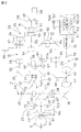
図1は本発明の実施例に係る眼科装置であり、図1(A)は該眼科装置の側面図を示し、図1(B)は該眼科装置の背面図を示している。
図2は本発明の実施例に係る眼科装置の光学系の配置を示す光学配置図である。
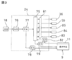
図3は本発明の実施例に係る眼科装置の制御系の構成を示すブロック図である。
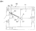
図4は本発明の実施例に係る眼科装置によるX軸方向及びY軸方向のアライメントを説明する説明図である。
図5は本発明の実施例に係る眼科装置のアライメント画面の変更を説明する説明図であり、図5(A)はアライメント画面の切替え前を示す説明図であり、図5(B)はアライメント画面の切替え後を示す説明図であり、図5(C)は切替えたアライメント画面によるZ軸方向のアライメントを示す説明図である。
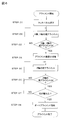
図6は本発明の実施例に係る眼科装置によるアライメントを説明するフローチャートである。
図7は本発明の実施例に係る眼科装置のアライメント画面の変形例を示す説明図である。
図2は本発明の実施例に係る眼科装置の光学系の配置を示す光学配置図である。
図3は本発明の実施例に係る眼科装置の制御系の構成を示すブロック図である。
図4は本発明の実施例に係る眼科装置によるX軸方向及びY軸方向のアライメントを説明する説明図である。
図5は本発明の実施例に係る眼科装置のアライメント画面の変更を説明する説明図であり、図5(A)はアライメント画面の切替え前を示す説明図であり、図5(B)はアライメント画面の切替え後を示す説明図であり、図5(C)は切替えたアライメント画面によるZ軸方向のアライメントを示す説明図である。
図6は本発明の実施例に係る眼科装置によるアライメントを説明するフローチャートである。
図7は本発明の実施例に係る眼科装置のアライメント画面の変形例を示す説明図である。
以下、図面を参照しつつ本発明の実施例を説明する。
先ず、図1(A)、図1(B)に於いて、本発明の実施例に係る眼科装置1について説明する。
該眼科装置1は、ベース部2と、該ベース部2上に設けられた検眼ヘッド3と、該検眼ヘッド3の前方に設けられた顎受部4と、該顎受部4と一体に設けられた額当て5とから構成され、被検者は前記顎受部4に顎を置き、前記額当て5に額を当てた状態で検査を受ける様になっている。
前記検眼ヘッド3の内部には、図1(A)に示される様に、検眼部6が設けられ、該検眼部6には観察・撮影用の観察光学系や、屈折力等を測定する測定光学系が設けられている。前記検眼部6により、被検者の前眼部、被検眼の角膜、眼底等が観察・撮影可能であり、眼底の検査等も行える様になっている。
前記検眼ヘッド3の被検者に対面する側には、複数の前眼部照明用の光源(図示せず)が所定の間隔で環状に配置されている。該光源は、角膜形状を測定する測定光源としても用いられる。
又、前記ベース部2には、図1(A)に示される様に、前記検眼ヘッド3を駆動する為の駆動部8が設けられている。該駆動部8には、例えば図示しないパルスモータが用いられる。
前記検眼ヘッド3は、該検眼ヘッド3に設けられた液晶ディスプレイ等の表示手段9より操作を行うことで、被検眼に対して上下方向、左右方向、前後方向に駆動される。
該表示手段9はタッチパネル11となっており、操作部を兼ねている。該タッチパネル11はピクセル(画素)の集合により構成され、該タッチパネル11には画面の中心(後述する主光軸O1)を原点とした座標系が設定される。各ピクセルは画面の中心を原点とした任意の2軸(例えばX軸、Y軸)の座標により表すことができると共に、表示される画面を切替えることで先の2軸以外の軸(例えばZ軸)の座標についても表すことができる。又、前記タッチパネル11は、例えば指等で接触、或は押下することで、押下した位置のピクセル(押下ピクセル位置)の座標(例えば(X,Y)座標)をアナログ信号で出力可能となっており、前記タッチパネル11を押下し、或はスライドすることにより各種の操作が行われる様になっている。
次に、図2に於いて、前記検眼部6の光学系の一例を説明する。尚、該光学系は図示しないケース内にまとめて配置される。
図2中、15は被検眼Eを固視・雲霧させる為に指標を眼底Erに投影する固視標投影光学系、16は前記被検眼Eの前眼部Efを観察する観察光学系、17は照準スケールをCCD18に投影するスケール投影光学系、19は前記被検眼Eの屈折力を測定する為のパターン光束を眼底Erに投影するパターン光束投影光学系(測定光学系)、21は眼底Erから反射された光束を前記CCD18に受光させる受光光学系(測定光学系)、22は光軸と垂直な方向のアライメント状態を検出する為の指標光を前記被検眼Eに向けて投影するアライメント光投影系、23は前記被検眼Eと装置本体(前記検眼ヘッド3)との間の作動距離を検出する為の作動距離検出光学系、24は信号処理部を示している。尚、前記パターン光束投影光学系19と前記受光光学系21は前記検眼部6の光学系を構成している。
前記固視標投影光学系15は、光源25、コリメータレンズ26、指標板27、リレーレンズ28、ミラー29、リレーレンズ31、ダイクロイックミラー32、ダイクロイックミラー33、対物レンズ34を具備している。
前記光源25から射出された可視光は、前記コリメータレンズ26によって平行光束とされた後、前記指標板27を透過する。該指標板27には、前記被検眼Eを固視・雲霧させる為のターゲットミラーが設けられている。前記指標板27を透過したターゲット光束は、前記リレーレンズ28を透過して前記ミラー29により反射され、前記リレーレンズ31を経て前記ダイクロイックミラー32に導かれ、又該ダイクロイックミラー32により反射されて光学系の主光軸O1に導かれ、前記ダイクロイックミラー33を透過した後、前記対物レンズ34を経て前記被検眼Eに導かれる。
前記光源25、前記コリメータレンズ26、前記指標板27は指標ユニット35を構成し、該指標ユニット35は前記被検眼Eを固視・雲霧させる為に、駆動モータ36(図3参照)によって、前記固視標投影光学系15の光軸O2に沿って一体に移動可能とされている。
前記観察光学系16は、照明光源37、前記対物レンズ34、前記ダイクロイックミラー33、絞り37′を有するリレーレンズ38、ミラー39、リレーレンズ41、ダイクロイックミラー42、結像レンズ43、CCD(撮像手段)18を有している。
前記照明光源37から射出された照明光束は、前記被検眼Eの前眼部Efを照明する。該前眼部Efで反射された照明光束は、前記対物レンズ34を経て前記ダイクロイックミラー33に反射される。その後、照明光束は前記リレーレンズ38の前記絞り37′を通過し、前記ミラー39により光軸O5に沿って反射された後、前記リレーレンズ41、前記ダイクロイックミラー42を透過して、前記結像レンズ43により前記CCD18に導かれ、該CCD18の撮像面に後述する前眼部像が形成される。
前記スケール投影光学系17は、光源44、照準スケールを有するコリメータレンズ45、リレーレンズ46、前記ダイクロイックミラー33、前記絞り37′を有する前記リレーレンズ38、前記ミラー39、前記リレーレンズ41、前記ダイクロイックミラー42、前記結像レンズ43、前記CCD18を有している。
前記光源44から射出された光束は、前記コリメータレンズ45を透過する際に平行光束とされ、前記リレーレンズ46、前記ダイクロイックミラー33、前記リレーレンズ38を経て前記ミラー39により光軸O5に沿って反射され、前記リレーレンズ41、前記ダイクロイックミラー42を経て前記結像レンズ43によって前記CCD18に結像される。該CCD18の撮像面からの映像信号は、前記信号処理部24を介して前記表示手段9に入力され、該表示手段9に前眼部像Ef′が表示されると共に、アライメントマーク47,48が表示される。尚、アライメント完了後の撮影、測定時には、前記照明光源37、前記光源44は消灯される。
前記アライメントマーク47はアライメント完了領域(測定可能エリア)の範囲を示すものであり、前記アライメントマーク48は粗アライメントの領域範囲を示すと共に、後述するモード切替領域を示すものである。
前記パターン光束投影光学系19は、光源49、コリメータレンズ51、円錐プリズム52、リング指標板53、リレーレンズ54、ミラー55、リレーレンズ56、穴あきプリズム57、前記ダイクロイックミラー32、前記ダイクロイックミラー33、前記対物レンズ34を有している。
前記光源49と前記リング指標板53とは光学的に共役であり、該リング指標板53と前記被検眼Eの瞳孔EPとは光学的に共役な位置に配置されている。又、前記光源49、前記コリメータレンズ51、前記円錐プリズム52、前記リング指標板53は、指標ユニット58を構成し、該指標ユニット58は駆動モータ59(図3参照)により光軸O3に沿って進退する様駆動される。
前記光源49から射出された光束は、前記コリメータレンズ51によって平行光束とされ、前記円錐プリズム52を透過して前記リング指標板53に導かれる。該リング指標板53にはリング状のパターンが形成されており、該リング指標板53に導かれた光束は、前記パターン部分を透過してパターン光束となる。該パターン光束は、前記リレーレンズ54を透過した後、前記ミラー55により反射され、前記リレーレンズ56を透過して前記穴あきプリズム57の反射面により反射され、主光軸O1に沿って前記ダイクロイックミラー32に導かれる。前記パターン光束が前記ダイクロイックミラー32,33を透過した後、前記対物レンズ34により眼底Erに結像される。
前記受光光学系21は、前記対物レンズ34、前記ダイクロイックミラー33,32、前記穴あきプリズム57の穴部57a、リレーレンズ61、ミラー62、リレーレンズ63、ミラー64、合焦レンズ65、ミラー66、前記ダイクロイックミラー42、前記結像レンズ43、前記CCD18を有している。尚、前記合焦レンズ65は、前記指標ユニット58と連動して、光軸O4に沿って移動可能となっている。
パターン反射光束は、前記パターン光束投影光学系19によって前記眼底Erに導かれ、該眼底Erで反射された前記パターン反射光束は、前記対物レンズ34により集光され、前記ダイクロイックミラー33,32を透過し、前記穴あきプリズム57の前記穴部57aへと導かれ、該穴部57aを通過する。該穴部57aを通過したパターン反射光束は、前記リレーレンズ61を透過して前記ミラー62によって反射され、前記リレーレンズ63を透過して前記ミラー64により反射される。該ミラー64により反射されたパターン反射光束は、前記合焦レンズ65を透過した後に前記ミラー66、前記ダイクロイックミラー42により反射され、前記結像レンズ43により前記CCD18に導かれる。これにより、該CCD18にパターン像が結像される。
前記アライメント光投影系22は、LED67、ピンホール68、コリメータレンズ69、ハーフミラー71を有し、前記被検眼Eの角膜Cに向けてアライメント指標光束を投影するアライメント手段としての機能を有している。アライメント指標光束は、前記被検眼Eに向けて平行光として投影され、該被検眼Eの前記角膜Cに於いて反射され、前記観察光学系16により前記CCD18上にアライメント指標像(輝点像)Tが投影される。輝点像Tが前記アライメントマーク47内に位置すると、アライメント完了と判断される。
前記固視標投影光学系15、前記観察光学系16、前記パターン光束投影光学系19、前記受光光学系21、前記アライメント光投影系22は前記主光軸O1を共通に有している。
前記作動距離検出光学系23は、前記被検眼Eと前記検眼ヘッド3との間の作動距離を検出するアライメント手段としての機能を有する。前記作動距離検出光学系23は、それぞれ主光軸O1に関して左右対称な有限距離指標投影系72R、72Lを有し、該有限距離指標投影系72R、72Lは有限距離から指標を投影する様になっている。又、該有限距離指標投影系72R、72Lは光源73からの光束を指標光束として前記被検眼Eに左右の斜めから投影する。
前記有限距離指標投影系72R、72Lからの指標光束は、前記被検眼Eの前記角膜Cで反射され、前記観察光学系16により前記CCD18上に結像される。前記信号処理部24は、前記CCD18からの出力に基づいて、前記有限距離指標投影系72R、72Lからの指標光束による指標像72R′、72L′を前記表示手段9に表示させる。尚、前記CCD18上には前記指標像72R′、72L′と同じ指標像が結像されている。これらの指標像が前記CCD18上で一定の位置関係になった場合、作動距離が測定に適した距離Woになったとして検出される。
前記信号処理部24は、図3に示す様に、演算制御部75、A/D変換器76、フレームメモリ77、D/A変換器78、D/A変換器79、A/D変換器82、モータ駆動回路81とを有している。
前記演算制御部75は、CPU、ROM、RAM、入出力回路を有すると共に、各パルスモータを駆動制御する駆動制御手段と眼特性等を演算する演算手段とを兼ね、演算結果等はRAMに記憶される。
又、前記演算制御部75は、瞳孔位置検出手段としての機能と演算手段としての機能を有している。前記瞳孔位置検出手段は画像上での瞳孔の位置を検出し、前記演算手段は前記瞳孔位置検出手段が検出した瞳孔の中心位置又は輝点像Tの位置と、前記CCD18により撮像された画像とに基づいて、前記被検眼Eの瞳孔中心と前記パターン光束投影光学系19の主光軸O1との離間距離と、前記受光光学系21の主光軸O1の位置(アライメント目標位置G)を基準にした瞳孔中心位置の方向とを算出する様になっている。尚、アライメント目標位置Gは、前記表示手段9に表示される画面の中心、即ち前記タッチパネル11から出力される座標の原点と合致している。
又、前記演算制御部75は、前記表示手段9の前記タッチパネル11から出力されたX座標及びY座標、或は切替えられた画面のZ座標を基に、X軸方向及びY軸方向、或はZ軸方向のモータ駆動量及び移動速度を演算する。前記演算制御部75は、入力されたX座標及びY座標、或はZ座標とアライメント目標位置Gとの距離を基に、距離が大きければ移動速度が速くなり、距離が小さければ移動速度が遅くなる様移動速度を演算し、前記モータ駆動回路81へ駆動命令を行う機能を有している。該モータ駆動回路81へ駆動命令を行うことで、前記駆動モータ36,59の駆動が制御されると共に、移動手段であるX軸駆動モータ83、Y軸駆動モータ84、Z軸駆動モータ85の駆動が制御され、前記X軸駆動モータ83、前記Y軸駆動モータ84、前記Z軸駆動モータ85により、前記検視ヘッド3がX軸方向、Y軸方向、Z軸方向に駆動される様になっている。
尚、前記X軸駆動モータ83が前記検眼ヘッド3を左右方向(X軸方向)に移動させ、前記Y軸駆動モータ84が前記検視ヘッド3を上下方向(Y軸方向)に移動させ、前記Z軸駆動モータ85が前記検視ヘッド3を前後方向(Z軸方向)に移動させる。
又、前記演算制御部75は、前記光源25、前記照明光源37、前記光源44、前記光源49、前記LED67、前記光源73の各種光源の点灯制御を行う様、図示しないドライバに接続されている。
前記演算制御部75は、前記CCD18に受光された輝点像T、指標像72R′、指標像72L′の受光位置を演算し、演算結果に基づき、アライメント目標位置G迄の距離や方向を演算する。
以下、X軸方向とY軸方向の粗アライメント、Z軸方向の粗アライメントを行う場合の移動速度の演算方法について説明する。
前記タッチパネル11の所定の位置が押下されると、該タッチパネル11から押下位置にある押下ピクセル位置のX座標、Y座標を示すアナログ信号が出力され、前記A/D変換器82にてデジタル信号に変換された後、前記演算制御部75へと入力され、以下の式に基づきX軸方向、Y軸方向に於ける移動速度が演算される。
ΔXpulse=(Xcenter−Xtouch)×PulseRatio
ΔYpulse=(Ycenter−Ytouch)×PulseRatio
上記式の様に、該演算制御部75は、押下ピクセル位置とアライメント目標位置Gとの位置の差、即ち押下ピクセル位置とアライメント目標位置Gとの画面上の距離を求め、求めた距離に予め距離に対応して設定されたパルスレート変換係数(PulseRatio)を掛けることで、X軸方向に於ける移動速度、Y軸方向に於ける移動速度(ΔXpulse、ΔYpulse)を演算する。
尚、X軸方向に於ける移動速度、Y軸方向に於ける移動速度の計算結果の符号(十又は一)は、モータ駆動系の実装に合わせて適宜CW、CCWを設定することで、アライメント目標位置Gと押下ピクセル位置との距離の大きさに対応して前記検眼ヘッド3の移動速度を可変とすることができる。
又、前記表示手段9の表示画面を切替えた後、Z軸方向に於いても同様に、前記タッチパネル11の所定の位置が押下されることで、該タッチパネル11から押下位置にある押下ピクセル位置のZ座標を示すアナログ信号が出力され、前記A/D変換器82にてデジタル信号に変換された後、前記演算制御部75へと入力され、以下の式に基づきZ軸方向に於ける移動速度が演算される。
ΔZpulse=(Zcenter−Ztouch)×PulseRatio
上記式の様に、該演算制御部75は押下ピクセル位置とアライメント目標位置Gとの画面上の距離を求め、求めた距離に予め距離に対応して設定されたパルスレート変換係数(PulseRatio)を掛けることで、Z軸方向に於ける移動速度(ΔZpulse)を演算する。又、Z軸方向に於ける移動速度の計算結果の符号(十又は一)は、モータ駆動系の実装に合わせて適宜CW、CCWを設定することで、アライメント目標位置Gと押下ピクセル位置との距離の大きさに対応して前記検眼ヘッド3の移動速度を可変とすることができる。
図4は前記表示手段9に表示された、X軸方向及びY軸方向の粗アライメントを行う為のXY軸アライメント画面90を示している。又、図4中、91は前記検眼ヘッド3の進行方向を示す方向バーであり、92は該方向バー91を構成する複数の速度目盛りであり、93は指94により前記タッチパネル11を押下された際の押下ピクセル位置を示す速度表示目盛りとなっており、前記アライメントマーク48の内側にはモード切替領域95が形成されている。
前記タッチパネル11の所定の位置を押下することで前記検眼ヘッド3の進行方向が決定され、押下ピクセル位置とアライメント目標位置Gとを結ぶ様に前記方向バー91が表示される。又、押下ピクセル位置に位置する前記速度目盛り92は、前記速度表示目盛り93として拡大されると共に点灯し、前記検眼ヘッド3は前記方向バー91の延びる方向にアライメント目標位置Gから押下ピクセル位置迄の距離に応じた速度で移動する。
本実施例に於いては、アライメント目標位置Gに近い位置を押下すれば前記検眼ヘッド3が低速で移動し、アライメント目標位置Gから遠い位置を押下すれば前記検眼ヘッド3が高速で移動する様設定されており、前記タッチパネル11を押下している間は前記検眼ヘッド3が前記方向バー91の延びる方向へと移動し続け、前記タッチパネル11の押下状態を解除することで前記検眼ヘッド3が停止する様になっている。
又、前記検眼ヘッド3の移動中、前記演算制御部75は押下ピクセル位置の座標を基に逐次進行方向を決定すると共に移動速度を演算しており、前記タッチパネル11の押下を維持した状態で、前記指94がずらされた場合には、前記演算制御部75は決定した進行方向及び演算した移動速度を基に前記モータ駆動回路81を制御する前記演算制御部75による前記モータ駆動回路81の制御により前記指94のずれに追従して進行方向、移動速度を調整しながら前記検眼ヘッド3を移動させることができる。
Z軸方向の粗アライメントを行う場合には、前記アライメントマーク48の内側の領域にある前記モード切替領域95に所定時間前記指94を留める。前記モード切替領域95に所定時間前記指94を留めることで(図5(A)参照)、前記演算制御部75が前記D/A変換器79を介して前記表示手段9に信号を出力し、前記表示手段9の表示を図5(B)に示される様な、縦軸をZ軸としたZ軸アライメント画面96へと切替える。
該Z軸アライメント画面96に於いては、進行方向を示す速度目盛り97が矢印にて表示される様になっており、前記XY軸アライメント画面90と同様、押下ピクセル位置に位置する前記速度目盛り97が速度表示目盛り98として点灯し(図5(C)参照)、押下ピクセル位置とアライメント目標位置Gとの距離に対応して前記検眼ヘッド3のZ軸方向に於ける移動速度が変動する様になっている。
次に、前記眼科装置1により、前記被検眼Eの撮影、眼機能の測定を行う場合について説明する。
先ず、図示しない電源を入れ、前記顎受部4に被検者(患者)の顎を載せる。次に、図示しない操作部を操作して前記観察光学系16の前記照明光源37を点灯させると共に、前記固視標投影光学系15の前記光源25を点灯させる。前記照明光源37の点灯により前記被検眼Eの前眼部Efが照明される。又、前記固視標投影光学系15の前記光源25の点灯により被検者に固視標が提示され、前記アライメント光投影系22の前記LED67等が点灯され、更に前記顎受部4の高さ等の調整が行われる。
この時、前記観察光学系16の前記照明光源37の点灯によって前眼部Efが照明されていることにより、前記観察光学系16の前記CCD18の撮像面上に前眼部像Ef′が結像され、前記A/D変換器76にてデジタル信号に変換された後、前記フレームメモリ77に前眼部像Ef′が記憶される。前記フレームメモリ77に記憶された前眼部像Ef′は、前記D/A変換器78によりアナログ信号へと変換され、前記表示手段9の画面、即ち前記XY軸アライメント画面90に表示される。
次に、輝点像Tが前記アライメントマーク47内へと入る様前記検眼ヘッド3を移動させるアライメント工程、即ち手動で行われる粗アライメントと、前記アライメントマーク48内に輝点像Tが入った場合に自動で行われるオートアライメントについて、図6のフローチャートを用いて説明する。
STEP01 前記表示手段9の画面には前記XY軸アライメント画面90が表示されており、前記タッチパネル11の瞳孔像Ea′方向の所定の位置が押下されると、前記タッチパネル11から押下ピクセル位置のX座標及びY座標を示す信号が出力され、前記演算制御部75が押下ピクセル位置のX座標及びY座標を基に進行方向を決定すると共に、アライメント目標位置Gとの距離を求め、求めた距離を基にX軸方向に於ける移動速度、Y軸方向に於ける移動速度を演算する。
各軸方向の移動速度が演算されると、前記演算制御部75が前記モータ駆動回路81に駆動命令を出すことで、該モータ駆動回路81が前記X軸駆動モータ83及び前記Y軸駆動モータ84を演算された移動速度に従って同時に駆動させ、前記検眼ヘッド3を移動させる。
STEP02 該検眼ヘッド3の移動中、前記タッチパネル11の押下を維持した状態で、前記指94をずらすことで、前記演算制御部75が押下ピクセル位置のX座標及びY座標から逐次演算している移動速度を基に、前記モータ駆動回路81を制御する。即ち、前記方向バー91を旋回させることで進行方向を調整しつつ、又前記速度表示目盛り93を中心側或は外周側へとずらすことで移動速度を調整しつつ、前記瞳孔像Ea′に向って前記検眼ヘッド3を移動させ、X軸方向、Y軸方向の粗アライメントを行う。
STEP03 STEP02の処理にて該検眼ヘッド3を移動させ、X軸方向及びY軸方向の粗アライメントが完了したかどうかが判断される。即ち輝点像Tが前記アライメントマーク48内に入っているかどうかが判断される。該アライメントマーク48内に輝点像Tが入っていなければ、前記アライメントマーク48内に輝点像Tが入る迄STEP02の処理が行われる。
STEP04 輝点像Tが前記アライメントマーク48内に入ったと判断されると、次に前記タッチパネル11の押下を維持した状態で、前記指94を前記モード切替領域95へと移動させ、該モード切替領域95内に所定時間留めることで、前記演算制御部75が前記表示手段9の画面を前記XY軸アライメント画面90から前記Z軸アライメント画面96へと切替える。
STEP05 前記表示手段9の画面が前記Z軸アライメント画面96へと切替った状態で、前記タッチパネル11の所定の位置が押下されると、前記制御演算部75が押下ピクセル位置のZ座標を基に進行方向を決定すると共に、前記Z軸アライメント画面96中に於ける押下ピクセル位置のZ座標とアライメント目標位置Gとの距離を求め、求めた距離を基にZ軸方向に於ける移動速度を演算する。
Z軸方向の移動速度が演算されると、前記演算制御部75が前記モータ駆動回路81に駆動命令を出すことで、該モータ駆動回路81が前記Z軸駆動モータ85を演算された移動速度で駆動させ、前記検眼ヘッド3を移動させる。
該検眼ヘッド3の移動中、前記タッチパネル11の押下を維持した状態で、前記指94を上下方向にずらすことで、前記演算制御部75が押下ピクセル位置のZ座標を基に逐次進行方向を決定すると共に移動速度を演算し、前記モータ駆動回路81を制御する。即ち進行方向、移動速度を調整しつつ前記検眼ヘッド3を移動させる。
STEP06 STEP05の処理にて該検眼ヘッド3を移動させ、Z軸方向の粗アライメントが完了したか、即ち前記瞳孔像Ea′が合焦位置又は合焦位置の近傍に来たかどうかが判断される。合焦位置又は合焦位置の近傍に該瞳孔像Ea′が来ていなければ、合焦位置又は合焦位置の近傍に該瞳孔像Ea′が来る迄STEP06の処理が行われる。
STEP07 STEP06にて該瞳孔像Ea′が合焦位置又は合焦位置の近傍に来た、即ちZ軸方向の粗アライメントが完了したと判断されると、次に前記タッチパネル11から前記指94が離れたかどうかが判断される。該指94が離れていない、即ち合焦位置又は合焦位置の近傍を越えて前記検眼ヘッド3が移動した場合には、STEP06及びSTEP07の処理が再度行われる。
STEP08 STEP07にて前記瞳孔像Ea′が合焦位置又は合焦位置の近傍に来た状態で、前記タッチパネル11から前記指94が離れる、即ちX軸Y軸及びZ軸の粗アライメントが完了すると、次に前記制御演算部75の駆動命令によりX軸Y軸及びZ軸のオートアライメントが行われる。オートアライメントでは、輝点像Tが前記アライメントマーク47内に入る様前記モータ駆動回路81が前記X軸駆動モータ83及び前記Y軸駆動モータ84を駆動させると共に、前記瞳孔像Ea′が合焦位置に来る様に前記Z軸駆動モータ85を駆動させ、オートアライメントが完了することでアライメント工程が完了する。
アライメントが完了した後は、アライメント完了位置に於いて、前記眼科装置1により前記被検眼Eの撮影、又は眼機能の測定等所定の処理が行われる。
上述の様に、本実施例では、前記検眼ヘッド3の移動中、即ち主光軸O1の移動中に、前記演算制御部75が押下ピクセル位置のX座標及びY座標、或はZ座標を基に逐次進行方向を決定していると共に移動速度を演算しており、前記タッチパネル11の押下を維持した状態で、前記指94をずらすことで、前記演算制御部75が決定した進行方向及び演算した移動速度に基づき前記モータ駆動回路81を制御し、前記X軸駆動モータ83、前記Y軸駆動モータ84、前記Z軸駆動モータ85を駆動させる。即ち、ずらされた前記指94に追従して移動中の前記検眼ヘッド3の進行方向及び移動速度がリアルタイムで調整される様になっている。
主光軸O1のアライメント中の進行方向が調整可能であるので、主光軸O1の進行方向が輝点像Tとずれていた場合であっても、前記タッチパネル11から前記指94を離して前記検眼ヘッド3の移動を停止した後に、再度前記タッチパネル11を押下して前記輝点像Tに向って前記検眼ヘッド3を移動させる必要がなく、前記タッチパネル11による柔軟な操作が可能となり、粗アライメントを行う際の操作性を向上させることができる。
又、主光軸O1の粗アライメント中の移動速度が調整可能であるので、輝点像Tがアライメント目標位置Gから遠い場合には、前記タッチパネル11のアライメント目標位置Gから離れた位置を押下し前記検眼ヘッド3の移動速度を速くする。又、輝点像Tがアライメント目標位置Gに近づいた場合には、近づいた輝点像Tの軌跡をなぞる様に前記指94をアライメント目標位置Gに近づけていくことで、主光軸O1の移動速度を遅くすることができ、粗アライメント時間の短縮及び操作性の向上を図ることができる。
又、X軸方向及びY軸方向の粗アライメントが完了した後、前記指94を前記モード切替領域95に所定時間留めることで、前記表示手段9に表示される画面を前記XY軸アライメント画面90から前記Z軸アライメント画面96へと切替えられる様になっているので、X軸、Y軸、Z軸の3軸の粗アライメントを全て同じインターフェイスで行うことができ、操作性を向上させることができる。
尚、オートアライメントができない被検眼や病眼の撮影や測定を行う場合には、前記Z軸アライメント画面96に於いて、前記タッチパネル11から前記指94を離すと、該指94を離した位置で前記眼科装置1が前記被検眼Eや眼機能の測定等所定の処理を行う様に設定する。この様に設定し、前記タッチパネル11上での操作により、前記瞳孔像Ea′が合焦位置に来る様Z軸方向に前記検眼ヘッド3を移動させ、前記瞳孔像Ea′が合焦位置に来た時に前記指94を離す様にすることで、オートアライメントができない被検眼や病眼の測定を行える可能性を高くすることができる。
尚、本実施例に於いては、先ず前記XY軸アライメント画面90に於いて、X軸方向、Y軸方向の粗アライメントを行った後、前記Z軸アライメント画面96に於いてZ軸方向の粗アライメントを行っているが、図7に示される様に、横軸をX軸、縦軸をZ軸としてXZ軸アライメント画面99にてX軸方向とZ軸方向の粗アライメントを行った後、Y軸方向の粗アライメントを行う様にしてもよい。
この場合、前記XZ軸アライメント画面99にてX軸方向とZ軸方向の粗アライメントが終了した後、モード切替領域(図示せず)に一定時間指を留めることで、Y軸方向の粗アライメントを行う画面に切替え、Y軸方向の粗アライメントを行うことで、本実施例と同様に、同じインターフェイスにてX軸、Y軸、Z軸の粗アライメントを行うことができる。
先ず、図1(A)、図1(B)に於いて、本発明の実施例に係る眼科装置1について説明する。
該眼科装置1は、ベース部2と、該ベース部2上に設けられた検眼ヘッド3と、該検眼ヘッド3の前方に設けられた顎受部4と、該顎受部4と一体に設けられた額当て5とから構成され、被検者は前記顎受部4に顎を置き、前記額当て5に額を当てた状態で検査を受ける様になっている。
前記検眼ヘッド3の内部には、図1(A)に示される様に、検眼部6が設けられ、該検眼部6には観察・撮影用の観察光学系や、屈折力等を測定する測定光学系が設けられている。前記検眼部6により、被検者の前眼部、被検眼の角膜、眼底等が観察・撮影可能であり、眼底の検査等も行える様になっている。
前記検眼ヘッド3の被検者に対面する側には、複数の前眼部照明用の光源(図示せず)が所定の間隔で環状に配置されている。該光源は、角膜形状を測定する測定光源としても用いられる。
又、前記ベース部2には、図1(A)に示される様に、前記検眼ヘッド3を駆動する為の駆動部8が設けられている。該駆動部8には、例えば図示しないパルスモータが用いられる。
前記検眼ヘッド3は、該検眼ヘッド3に設けられた液晶ディスプレイ等の表示手段9より操作を行うことで、被検眼に対して上下方向、左右方向、前後方向に駆動される。
該表示手段9はタッチパネル11となっており、操作部を兼ねている。該タッチパネル11はピクセル(画素)の集合により構成され、該タッチパネル11には画面の中心(後述する主光軸O1)を原点とした座標系が設定される。各ピクセルは画面の中心を原点とした任意の2軸(例えばX軸、Y軸)の座標により表すことができると共に、表示される画面を切替えることで先の2軸以外の軸(例えばZ軸)の座標についても表すことができる。又、前記タッチパネル11は、例えば指等で接触、或は押下することで、押下した位置のピクセル(押下ピクセル位置)の座標(例えば(X,Y)座標)をアナログ信号で出力可能となっており、前記タッチパネル11を押下し、或はスライドすることにより各種の操作が行われる様になっている。
次に、図2に於いて、前記検眼部6の光学系の一例を説明する。尚、該光学系は図示しないケース内にまとめて配置される。
図2中、15は被検眼Eを固視・雲霧させる為に指標を眼底Erに投影する固視標投影光学系、16は前記被検眼Eの前眼部Efを観察する観察光学系、17は照準スケールをCCD18に投影するスケール投影光学系、19は前記被検眼Eの屈折力を測定する為のパターン光束を眼底Erに投影するパターン光束投影光学系(測定光学系)、21は眼底Erから反射された光束を前記CCD18に受光させる受光光学系(測定光学系)、22は光軸と垂直な方向のアライメント状態を検出する為の指標光を前記被検眼Eに向けて投影するアライメント光投影系、23は前記被検眼Eと装置本体(前記検眼ヘッド3)との間の作動距離を検出する為の作動距離検出光学系、24は信号処理部を示している。尚、前記パターン光束投影光学系19と前記受光光学系21は前記検眼部6の光学系を構成している。
前記固視標投影光学系15は、光源25、コリメータレンズ26、指標板27、リレーレンズ28、ミラー29、リレーレンズ31、ダイクロイックミラー32、ダイクロイックミラー33、対物レンズ34を具備している。
前記光源25から射出された可視光は、前記コリメータレンズ26によって平行光束とされた後、前記指標板27を透過する。該指標板27には、前記被検眼Eを固視・雲霧させる為のターゲットミラーが設けられている。前記指標板27を透過したターゲット光束は、前記リレーレンズ28を透過して前記ミラー29により反射され、前記リレーレンズ31を経て前記ダイクロイックミラー32に導かれ、又該ダイクロイックミラー32により反射されて光学系の主光軸O1に導かれ、前記ダイクロイックミラー33を透過した後、前記対物レンズ34を経て前記被検眼Eに導かれる。
前記光源25、前記コリメータレンズ26、前記指標板27は指標ユニット35を構成し、該指標ユニット35は前記被検眼Eを固視・雲霧させる為に、駆動モータ36(図3参照)によって、前記固視標投影光学系15の光軸O2に沿って一体に移動可能とされている。
前記観察光学系16は、照明光源37、前記対物レンズ34、前記ダイクロイックミラー33、絞り37′を有するリレーレンズ38、ミラー39、リレーレンズ41、ダイクロイックミラー42、結像レンズ43、CCD(撮像手段)18を有している。
前記照明光源37から射出された照明光束は、前記被検眼Eの前眼部Efを照明する。該前眼部Efで反射された照明光束は、前記対物レンズ34を経て前記ダイクロイックミラー33に反射される。その後、照明光束は前記リレーレンズ38の前記絞り37′を通過し、前記ミラー39により光軸O5に沿って反射された後、前記リレーレンズ41、前記ダイクロイックミラー42を透過して、前記結像レンズ43により前記CCD18に導かれ、該CCD18の撮像面に後述する前眼部像が形成される。
前記スケール投影光学系17は、光源44、照準スケールを有するコリメータレンズ45、リレーレンズ46、前記ダイクロイックミラー33、前記絞り37′を有する前記リレーレンズ38、前記ミラー39、前記リレーレンズ41、前記ダイクロイックミラー42、前記結像レンズ43、前記CCD18を有している。
前記光源44から射出された光束は、前記コリメータレンズ45を透過する際に平行光束とされ、前記リレーレンズ46、前記ダイクロイックミラー33、前記リレーレンズ38を経て前記ミラー39により光軸O5に沿って反射され、前記リレーレンズ41、前記ダイクロイックミラー42を経て前記結像レンズ43によって前記CCD18に結像される。該CCD18の撮像面からの映像信号は、前記信号処理部24を介して前記表示手段9に入力され、該表示手段9に前眼部像Ef′が表示されると共に、アライメントマーク47,48が表示される。尚、アライメント完了後の撮影、測定時には、前記照明光源37、前記光源44は消灯される。
前記アライメントマーク47はアライメント完了領域(測定可能エリア)の範囲を示すものであり、前記アライメントマーク48は粗アライメントの領域範囲を示すと共に、後述するモード切替領域を示すものである。
前記パターン光束投影光学系19は、光源49、コリメータレンズ51、円錐プリズム52、リング指標板53、リレーレンズ54、ミラー55、リレーレンズ56、穴あきプリズム57、前記ダイクロイックミラー32、前記ダイクロイックミラー33、前記対物レンズ34を有している。
前記光源49と前記リング指標板53とは光学的に共役であり、該リング指標板53と前記被検眼Eの瞳孔EPとは光学的に共役な位置に配置されている。又、前記光源49、前記コリメータレンズ51、前記円錐プリズム52、前記リング指標板53は、指標ユニット58を構成し、該指標ユニット58は駆動モータ59(図3参照)により光軸O3に沿って進退する様駆動される。
前記光源49から射出された光束は、前記コリメータレンズ51によって平行光束とされ、前記円錐プリズム52を透過して前記リング指標板53に導かれる。該リング指標板53にはリング状のパターンが形成されており、該リング指標板53に導かれた光束は、前記パターン部分を透過してパターン光束となる。該パターン光束は、前記リレーレンズ54を透過した後、前記ミラー55により反射され、前記リレーレンズ56を透過して前記穴あきプリズム57の反射面により反射され、主光軸O1に沿って前記ダイクロイックミラー32に導かれる。前記パターン光束が前記ダイクロイックミラー32,33を透過した後、前記対物レンズ34により眼底Erに結像される。
前記受光光学系21は、前記対物レンズ34、前記ダイクロイックミラー33,32、前記穴あきプリズム57の穴部57a、リレーレンズ61、ミラー62、リレーレンズ63、ミラー64、合焦レンズ65、ミラー66、前記ダイクロイックミラー42、前記結像レンズ43、前記CCD18を有している。尚、前記合焦レンズ65は、前記指標ユニット58と連動して、光軸O4に沿って移動可能となっている。
パターン反射光束は、前記パターン光束投影光学系19によって前記眼底Erに導かれ、該眼底Erで反射された前記パターン反射光束は、前記対物レンズ34により集光され、前記ダイクロイックミラー33,32を透過し、前記穴あきプリズム57の前記穴部57aへと導かれ、該穴部57aを通過する。該穴部57aを通過したパターン反射光束は、前記リレーレンズ61を透過して前記ミラー62によって反射され、前記リレーレンズ63を透過して前記ミラー64により反射される。該ミラー64により反射されたパターン反射光束は、前記合焦レンズ65を透過した後に前記ミラー66、前記ダイクロイックミラー42により反射され、前記結像レンズ43により前記CCD18に導かれる。これにより、該CCD18にパターン像が結像される。
前記アライメント光投影系22は、LED67、ピンホール68、コリメータレンズ69、ハーフミラー71を有し、前記被検眼Eの角膜Cに向けてアライメント指標光束を投影するアライメント手段としての機能を有している。アライメント指標光束は、前記被検眼Eに向けて平行光として投影され、該被検眼Eの前記角膜Cに於いて反射され、前記観察光学系16により前記CCD18上にアライメント指標像(輝点像)Tが投影される。輝点像Tが前記アライメントマーク47内に位置すると、アライメント完了と判断される。
前記固視標投影光学系15、前記観察光学系16、前記パターン光束投影光学系19、前記受光光学系21、前記アライメント光投影系22は前記主光軸O1を共通に有している。
前記作動距離検出光学系23は、前記被検眼Eと前記検眼ヘッド3との間の作動距離を検出するアライメント手段としての機能を有する。前記作動距離検出光学系23は、それぞれ主光軸O1に関して左右対称な有限距離指標投影系72R、72Lを有し、該有限距離指標投影系72R、72Lは有限距離から指標を投影する様になっている。又、該有限距離指標投影系72R、72Lは光源73からの光束を指標光束として前記被検眼Eに左右の斜めから投影する。
前記有限距離指標投影系72R、72Lからの指標光束は、前記被検眼Eの前記角膜Cで反射され、前記観察光学系16により前記CCD18上に結像される。前記信号処理部24は、前記CCD18からの出力に基づいて、前記有限距離指標投影系72R、72Lからの指標光束による指標像72R′、72L′を前記表示手段9に表示させる。尚、前記CCD18上には前記指標像72R′、72L′と同じ指標像が結像されている。これらの指標像が前記CCD18上で一定の位置関係になった場合、作動距離が測定に適した距離Woになったとして検出される。
前記信号処理部24は、図3に示す様に、演算制御部75、A/D変換器76、フレームメモリ77、D/A変換器78、D/A変換器79、A/D変換器82、モータ駆動回路81とを有している。
前記演算制御部75は、CPU、ROM、RAM、入出力回路を有すると共に、各パルスモータを駆動制御する駆動制御手段と眼特性等を演算する演算手段とを兼ね、演算結果等はRAMに記憶される。
又、前記演算制御部75は、瞳孔位置検出手段としての機能と演算手段としての機能を有している。前記瞳孔位置検出手段は画像上での瞳孔の位置を検出し、前記演算手段は前記瞳孔位置検出手段が検出した瞳孔の中心位置又は輝点像Tの位置と、前記CCD18により撮像された画像とに基づいて、前記被検眼Eの瞳孔中心と前記パターン光束投影光学系19の主光軸O1との離間距離と、前記受光光学系21の主光軸O1の位置(アライメント目標位置G)を基準にした瞳孔中心位置の方向とを算出する様になっている。尚、アライメント目標位置Gは、前記表示手段9に表示される画面の中心、即ち前記タッチパネル11から出力される座標の原点と合致している。
又、前記演算制御部75は、前記表示手段9の前記タッチパネル11から出力されたX座標及びY座標、或は切替えられた画面のZ座標を基に、X軸方向及びY軸方向、或はZ軸方向のモータ駆動量及び移動速度を演算する。前記演算制御部75は、入力されたX座標及びY座標、或はZ座標とアライメント目標位置Gとの距離を基に、距離が大きければ移動速度が速くなり、距離が小さければ移動速度が遅くなる様移動速度を演算し、前記モータ駆動回路81へ駆動命令を行う機能を有している。該モータ駆動回路81へ駆動命令を行うことで、前記駆動モータ36,59の駆動が制御されると共に、移動手段であるX軸駆動モータ83、Y軸駆動モータ84、Z軸駆動モータ85の駆動が制御され、前記X軸駆動モータ83、前記Y軸駆動モータ84、前記Z軸駆動モータ85により、前記検視ヘッド3がX軸方向、Y軸方向、Z軸方向に駆動される様になっている。
尚、前記X軸駆動モータ83が前記検眼ヘッド3を左右方向(X軸方向)に移動させ、前記Y軸駆動モータ84が前記検視ヘッド3を上下方向(Y軸方向)に移動させ、前記Z軸駆動モータ85が前記検視ヘッド3を前後方向(Z軸方向)に移動させる。
又、前記演算制御部75は、前記光源25、前記照明光源37、前記光源44、前記光源49、前記LED67、前記光源73の各種光源の点灯制御を行う様、図示しないドライバに接続されている。
前記演算制御部75は、前記CCD18に受光された輝点像T、指標像72R′、指標像72L′の受光位置を演算し、演算結果に基づき、アライメント目標位置G迄の距離や方向を演算する。
以下、X軸方向とY軸方向の粗アライメント、Z軸方向の粗アライメントを行う場合の移動速度の演算方法について説明する。
前記タッチパネル11の所定の位置が押下されると、該タッチパネル11から押下位置にある押下ピクセル位置のX座標、Y座標を示すアナログ信号が出力され、前記A/D変換器82にてデジタル信号に変換された後、前記演算制御部75へと入力され、以下の式に基づきX軸方向、Y軸方向に於ける移動速度が演算される。
ΔXpulse=(Xcenter−Xtouch)×PulseRatio
ΔYpulse=(Ycenter−Ytouch)×PulseRatio
上記式の様に、該演算制御部75は、押下ピクセル位置とアライメント目標位置Gとの位置の差、即ち押下ピクセル位置とアライメント目標位置Gとの画面上の距離を求め、求めた距離に予め距離に対応して設定されたパルスレート変換係数(PulseRatio)を掛けることで、X軸方向に於ける移動速度、Y軸方向に於ける移動速度(ΔXpulse、ΔYpulse)を演算する。
尚、X軸方向に於ける移動速度、Y軸方向に於ける移動速度の計算結果の符号(十又は一)は、モータ駆動系の実装に合わせて適宜CW、CCWを設定することで、アライメント目標位置Gと押下ピクセル位置との距離の大きさに対応して前記検眼ヘッド3の移動速度を可変とすることができる。
又、前記表示手段9の表示画面を切替えた後、Z軸方向に於いても同様に、前記タッチパネル11の所定の位置が押下されることで、該タッチパネル11から押下位置にある押下ピクセル位置のZ座標を示すアナログ信号が出力され、前記A/D変換器82にてデジタル信号に変換された後、前記演算制御部75へと入力され、以下の式に基づきZ軸方向に於ける移動速度が演算される。
ΔZpulse=(Zcenter−Ztouch)×PulseRatio
上記式の様に、該演算制御部75は押下ピクセル位置とアライメント目標位置Gとの画面上の距離を求め、求めた距離に予め距離に対応して設定されたパルスレート変換係数(PulseRatio)を掛けることで、Z軸方向に於ける移動速度(ΔZpulse)を演算する。又、Z軸方向に於ける移動速度の計算結果の符号(十又は一)は、モータ駆動系の実装に合わせて適宜CW、CCWを設定することで、アライメント目標位置Gと押下ピクセル位置との距離の大きさに対応して前記検眼ヘッド3の移動速度を可変とすることができる。
図4は前記表示手段9に表示された、X軸方向及びY軸方向の粗アライメントを行う為のXY軸アライメント画面90を示している。又、図4中、91は前記検眼ヘッド3の進行方向を示す方向バーであり、92は該方向バー91を構成する複数の速度目盛りであり、93は指94により前記タッチパネル11を押下された際の押下ピクセル位置を示す速度表示目盛りとなっており、前記アライメントマーク48の内側にはモード切替領域95が形成されている。
前記タッチパネル11の所定の位置を押下することで前記検眼ヘッド3の進行方向が決定され、押下ピクセル位置とアライメント目標位置Gとを結ぶ様に前記方向バー91が表示される。又、押下ピクセル位置に位置する前記速度目盛り92は、前記速度表示目盛り93として拡大されると共に点灯し、前記検眼ヘッド3は前記方向バー91の延びる方向にアライメント目標位置Gから押下ピクセル位置迄の距離に応じた速度で移動する。
本実施例に於いては、アライメント目標位置Gに近い位置を押下すれば前記検眼ヘッド3が低速で移動し、アライメント目標位置Gから遠い位置を押下すれば前記検眼ヘッド3が高速で移動する様設定されており、前記タッチパネル11を押下している間は前記検眼ヘッド3が前記方向バー91の延びる方向へと移動し続け、前記タッチパネル11の押下状態を解除することで前記検眼ヘッド3が停止する様になっている。
又、前記検眼ヘッド3の移動中、前記演算制御部75は押下ピクセル位置の座標を基に逐次進行方向を決定すると共に移動速度を演算しており、前記タッチパネル11の押下を維持した状態で、前記指94がずらされた場合には、前記演算制御部75は決定した進行方向及び演算した移動速度を基に前記モータ駆動回路81を制御する前記演算制御部75による前記モータ駆動回路81の制御により前記指94のずれに追従して進行方向、移動速度を調整しながら前記検眼ヘッド3を移動させることができる。
Z軸方向の粗アライメントを行う場合には、前記アライメントマーク48の内側の領域にある前記モード切替領域95に所定時間前記指94を留める。前記モード切替領域95に所定時間前記指94を留めることで(図5(A)参照)、前記演算制御部75が前記D/A変換器79を介して前記表示手段9に信号を出力し、前記表示手段9の表示を図5(B)に示される様な、縦軸をZ軸としたZ軸アライメント画面96へと切替える。
該Z軸アライメント画面96に於いては、進行方向を示す速度目盛り97が矢印にて表示される様になっており、前記XY軸アライメント画面90と同様、押下ピクセル位置に位置する前記速度目盛り97が速度表示目盛り98として点灯し(図5(C)参照)、押下ピクセル位置とアライメント目標位置Gとの距離に対応して前記検眼ヘッド3のZ軸方向に於ける移動速度が変動する様になっている。
次に、前記眼科装置1により、前記被検眼Eの撮影、眼機能の測定を行う場合について説明する。
先ず、図示しない電源を入れ、前記顎受部4に被検者(患者)の顎を載せる。次に、図示しない操作部を操作して前記観察光学系16の前記照明光源37を点灯させると共に、前記固視標投影光学系15の前記光源25を点灯させる。前記照明光源37の点灯により前記被検眼Eの前眼部Efが照明される。又、前記固視標投影光学系15の前記光源25の点灯により被検者に固視標が提示され、前記アライメント光投影系22の前記LED67等が点灯され、更に前記顎受部4の高さ等の調整が行われる。
この時、前記観察光学系16の前記照明光源37の点灯によって前眼部Efが照明されていることにより、前記観察光学系16の前記CCD18の撮像面上に前眼部像Ef′が結像され、前記A/D変換器76にてデジタル信号に変換された後、前記フレームメモリ77に前眼部像Ef′が記憶される。前記フレームメモリ77に記憶された前眼部像Ef′は、前記D/A変換器78によりアナログ信号へと変換され、前記表示手段9の画面、即ち前記XY軸アライメント画面90に表示される。
次に、輝点像Tが前記アライメントマーク47内へと入る様前記検眼ヘッド3を移動させるアライメント工程、即ち手動で行われる粗アライメントと、前記アライメントマーク48内に輝点像Tが入った場合に自動で行われるオートアライメントについて、図6のフローチャートを用いて説明する。
STEP01 前記表示手段9の画面には前記XY軸アライメント画面90が表示されており、前記タッチパネル11の瞳孔像Ea′方向の所定の位置が押下されると、前記タッチパネル11から押下ピクセル位置のX座標及びY座標を示す信号が出力され、前記演算制御部75が押下ピクセル位置のX座標及びY座標を基に進行方向を決定すると共に、アライメント目標位置Gとの距離を求め、求めた距離を基にX軸方向に於ける移動速度、Y軸方向に於ける移動速度を演算する。
各軸方向の移動速度が演算されると、前記演算制御部75が前記モータ駆動回路81に駆動命令を出すことで、該モータ駆動回路81が前記X軸駆動モータ83及び前記Y軸駆動モータ84を演算された移動速度に従って同時に駆動させ、前記検眼ヘッド3を移動させる。
STEP02 該検眼ヘッド3の移動中、前記タッチパネル11の押下を維持した状態で、前記指94をずらすことで、前記演算制御部75が押下ピクセル位置のX座標及びY座標から逐次演算している移動速度を基に、前記モータ駆動回路81を制御する。即ち、前記方向バー91を旋回させることで進行方向を調整しつつ、又前記速度表示目盛り93を中心側或は外周側へとずらすことで移動速度を調整しつつ、前記瞳孔像Ea′に向って前記検眼ヘッド3を移動させ、X軸方向、Y軸方向の粗アライメントを行う。
STEP03 STEP02の処理にて該検眼ヘッド3を移動させ、X軸方向及びY軸方向の粗アライメントが完了したかどうかが判断される。即ち輝点像Tが前記アライメントマーク48内に入っているかどうかが判断される。該アライメントマーク48内に輝点像Tが入っていなければ、前記アライメントマーク48内に輝点像Tが入る迄STEP02の処理が行われる。
STEP04 輝点像Tが前記アライメントマーク48内に入ったと判断されると、次に前記タッチパネル11の押下を維持した状態で、前記指94を前記モード切替領域95へと移動させ、該モード切替領域95内に所定時間留めることで、前記演算制御部75が前記表示手段9の画面を前記XY軸アライメント画面90から前記Z軸アライメント画面96へと切替える。
STEP05 前記表示手段9の画面が前記Z軸アライメント画面96へと切替った状態で、前記タッチパネル11の所定の位置が押下されると、前記制御演算部75が押下ピクセル位置のZ座標を基に進行方向を決定すると共に、前記Z軸アライメント画面96中に於ける押下ピクセル位置のZ座標とアライメント目標位置Gとの距離を求め、求めた距離を基にZ軸方向に於ける移動速度を演算する。
Z軸方向の移動速度が演算されると、前記演算制御部75が前記モータ駆動回路81に駆動命令を出すことで、該モータ駆動回路81が前記Z軸駆動モータ85を演算された移動速度で駆動させ、前記検眼ヘッド3を移動させる。
該検眼ヘッド3の移動中、前記タッチパネル11の押下を維持した状態で、前記指94を上下方向にずらすことで、前記演算制御部75が押下ピクセル位置のZ座標を基に逐次進行方向を決定すると共に移動速度を演算し、前記モータ駆動回路81を制御する。即ち進行方向、移動速度を調整しつつ前記検眼ヘッド3を移動させる。
STEP06 STEP05の処理にて該検眼ヘッド3を移動させ、Z軸方向の粗アライメントが完了したか、即ち前記瞳孔像Ea′が合焦位置又は合焦位置の近傍に来たかどうかが判断される。合焦位置又は合焦位置の近傍に該瞳孔像Ea′が来ていなければ、合焦位置又は合焦位置の近傍に該瞳孔像Ea′が来る迄STEP06の処理が行われる。
STEP07 STEP06にて該瞳孔像Ea′が合焦位置又は合焦位置の近傍に来た、即ちZ軸方向の粗アライメントが完了したと判断されると、次に前記タッチパネル11から前記指94が離れたかどうかが判断される。該指94が離れていない、即ち合焦位置又は合焦位置の近傍を越えて前記検眼ヘッド3が移動した場合には、STEP06及びSTEP07の処理が再度行われる。
STEP08 STEP07にて前記瞳孔像Ea′が合焦位置又は合焦位置の近傍に来た状態で、前記タッチパネル11から前記指94が離れる、即ちX軸Y軸及びZ軸の粗アライメントが完了すると、次に前記制御演算部75の駆動命令によりX軸Y軸及びZ軸のオートアライメントが行われる。オートアライメントでは、輝点像Tが前記アライメントマーク47内に入る様前記モータ駆動回路81が前記X軸駆動モータ83及び前記Y軸駆動モータ84を駆動させると共に、前記瞳孔像Ea′が合焦位置に来る様に前記Z軸駆動モータ85を駆動させ、オートアライメントが完了することでアライメント工程が完了する。
アライメントが完了した後は、アライメント完了位置に於いて、前記眼科装置1により前記被検眼Eの撮影、又は眼機能の測定等所定の処理が行われる。
上述の様に、本実施例では、前記検眼ヘッド3の移動中、即ち主光軸O1の移動中に、前記演算制御部75が押下ピクセル位置のX座標及びY座標、或はZ座標を基に逐次進行方向を決定していると共に移動速度を演算しており、前記タッチパネル11の押下を維持した状態で、前記指94をずらすことで、前記演算制御部75が決定した進行方向及び演算した移動速度に基づき前記モータ駆動回路81を制御し、前記X軸駆動モータ83、前記Y軸駆動モータ84、前記Z軸駆動モータ85を駆動させる。即ち、ずらされた前記指94に追従して移動中の前記検眼ヘッド3の進行方向及び移動速度がリアルタイムで調整される様になっている。
主光軸O1のアライメント中の進行方向が調整可能であるので、主光軸O1の進行方向が輝点像Tとずれていた場合であっても、前記タッチパネル11から前記指94を離して前記検眼ヘッド3の移動を停止した後に、再度前記タッチパネル11を押下して前記輝点像Tに向って前記検眼ヘッド3を移動させる必要がなく、前記タッチパネル11による柔軟な操作が可能となり、粗アライメントを行う際の操作性を向上させることができる。
又、主光軸O1の粗アライメント中の移動速度が調整可能であるので、輝点像Tがアライメント目標位置Gから遠い場合には、前記タッチパネル11のアライメント目標位置Gから離れた位置を押下し前記検眼ヘッド3の移動速度を速くする。又、輝点像Tがアライメント目標位置Gに近づいた場合には、近づいた輝点像Tの軌跡をなぞる様に前記指94をアライメント目標位置Gに近づけていくことで、主光軸O1の移動速度を遅くすることができ、粗アライメント時間の短縮及び操作性の向上を図ることができる。
又、X軸方向及びY軸方向の粗アライメントが完了した後、前記指94を前記モード切替領域95に所定時間留めることで、前記表示手段9に表示される画面を前記XY軸アライメント画面90から前記Z軸アライメント画面96へと切替えられる様になっているので、X軸、Y軸、Z軸の3軸の粗アライメントを全て同じインターフェイスで行うことができ、操作性を向上させることができる。
尚、オートアライメントができない被検眼や病眼の撮影や測定を行う場合には、前記Z軸アライメント画面96に於いて、前記タッチパネル11から前記指94を離すと、該指94を離した位置で前記眼科装置1が前記被検眼Eや眼機能の測定等所定の処理を行う様に設定する。この様に設定し、前記タッチパネル11上での操作により、前記瞳孔像Ea′が合焦位置に来る様Z軸方向に前記検眼ヘッド3を移動させ、前記瞳孔像Ea′が合焦位置に来た時に前記指94を離す様にすることで、オートアライメントができない被検眼や病眼の測定を行える可能性を高くすることができる。
尚、本実施例に於いては、先ず前記XY軸アライメント画面90に於いて、X軸方向、Y軸方向の粗アライメントを行った後、前記Z軸アライメント画面96に於いてZ軸方向の粗アライメントを行っているが、図7に示される様に、横軸をX軸、縦軸をZ軸としてXZ軸アライメント画面99にてX軸方向とZ軸方向の粗アライメントを行った後、Y軸方向の粗アライメントを行う様にしてもよい。
この場合、前記XZ軸アライメント画面99にてX軸方向とZ軸方向の粗アライメントが終了した後、モード切替領域(図示せず)に一定時間指を留めることで、Y軸方向の粗アライメントを行う画面に切替え、Y軸方向の粗アライメントを行うことで、本実施例と同様に、同じインターフェイスにてX軸、Y軸、Z軸の粗アライメントを行うことができる。
1 眼科装置
3 検眼ヘッド
6 検眼部
8 駆動部
9 表示手段
11 タッチパネル
15 固視標投影光学系
16 観察光学系
18 CCD
21 受光光学系
22 アライメント光投影系
24 信号処理部
75 演算制御部
81 モータ駆動回路
83 X軸駆動モータ
84 Y軸駆動モータ
85 Z軸駆動モータ
90 XY軸アライメント画面
91 方向バー
92 速度目盛り
93 速度表示目盛り
95 モード切替領域
96 Z軸アライメント画面
97 速度目盛り
99 XZ軸アライメント画面
3 検眼ヘッド
6 検眼部
8 駆動部
9 表示手段
11 タッチパネル
15 固視標投影光学系
16 観察光学系
18 CCD
21 受光光学系
22 アライメント光投影系
24 信号処理部
75 演算制御部
81 モータ駆動回路
83 X軸駆動モータ
84 Y軸駆動モータ
85 Z軸駆動モータ
90 XY軸アライメント画面
91 方向バー
92 速度目盛り
93 速度表示目盛り
95 モード切替領域
96 Z軸アライメント画面
97 速度目盛り
99 XZ軸アライメント画面
Claims (6)
- 被検眼の撮影又は測定を行う光学系を有する検眼部と、前記被検眼に向けて該被検眼に対する前記検眼部の光学系のアライメントを行う為の指標光を投影するアライメント光投影系と、前記被検眼を撮像する撮像手段と、該撮像手段で撮像された前眼部を表示する表示手段と、前記検眼部と前記アライメント光投影系と前記撮像手段とが少なくとも設けられた検眼ヘッドと、該検眼ヘッドを前記被検眼に対して左右、上下、前後に移動させる移動手段と、該移動手段を制御して前記被検眼に対する前記検眼部の光学系のアライメントを行う制御手段とを具備し、前記表示手段はタッチパネルを有し、前記制御手段は押下された前記タッチパネルの押下ピクセル位置の座標を基に前記検眼ヘッドの進行方向を決定すると共に、前記押下ピクセル位置と前記表示手段に表示された画面の中心との距離に対応した前記検眼ヘッドの移動速度を演算し、該検眼ヘッドが決定された方向に演算された速度で移動する様制御する眼科装置。
- 前記制御手段は、前記検眼ヘッドの移動中前記タッチパネルの押下ピクセル位置の座標を基に逐次進行方向及び移動速度を演算しており、前記検眼ヘッドの移動中前記押下ピクセル位置の座標が変更されることで、前記検眼ヘッドの進行方向及び移動速度が変更される請求項1の眼科装置。
- 前記タッチパネルの押下が解除されることで前記検眼ヘッドの移動が停止される請求項1又は請求項2の眼科装置。
- オートアライメントの開始が可能である範囲が設定され、該範囲内で前記タッチパネルの押下が解除されると、押下が解除された位置にて前記制御手段がオートアライメントを開始する請求項3の眼科装置。
- 前記タッチパネルの押下が解除されると、押下が解除された位置にて前記制御手段が前記被検眼の撮影又は測定を行う請求項3の眼科装置。
- 前記表示手段中にはモード切替領域が形成され、該モード切替領域を所定時間押下し続けることで前記検眼ヘッドを移動させる前記移動手段の移動軸を変更可能に構成された請求項1~請求項5のうちいずれかの眼科装置。
Applications Claiming Priority (2)
| Application Number | Priority Date | Filing Date | Title |
|---|---|---|---|
| JP2013-010573 | 2013-01-23 | ||
| JP2013010573A JP6134518B2 (ja) | 2013-01-23 | 2013-01-23 | 眼科装置 |
Publications (1)
| Publication Number | Publication Date |
|---|---|
| WO2014115659A1 true WO2014115659A1 (ja) | 2014-07-31 |
Family
ID=51227451
Family Applications (1)
| Application Number | Title | Priority Date | Filing Date |
|---|---|---|---|
| PCT/JP2014/050875 Ceased WO2014115659A1 (ja) | 2013-01-23 | 2014-01-14 | 眼科装置 |
Country Status (2)
| Country | Link |
|---|---|
| JP (1) | JP6134518B2 (ja) |
| WO (1) | WO2014115659A1 (ja) |
Families Citing this family (4)
| Publication number | Priority date | Publication date | Assignee | Title |
|---|---|---|---|---|
| JP6396125B2 (ja) * | 2014-08-29 | 2018-09-26 | 株式会社トプコン | 眼科装置 |
| JP6880562B2 (ja) * | 2016-03-30 | 2021-06-02 | 株式会社ニデック | 眼科装置、および眼科装置制御プログラム |
| WO2018050297A1 (en) * | 2016-09-14 | 2018-03-22 | Essilor International | Systems and methods for vision testing |
| JP7519084B2 (ja) * | 2020-08-31 | 2024-07-19 | 株式会社トーメーコーポレーション | 眼科装置 |
Citations (2)
| Publication number | Priority date | Publication date | Assignee | Title |
|---|---|---|---|---|
| JP2006288610A (ja) * | 2005-04-08 | 2006-10-26 | Tomey Corporation | 眼科装置 |
| JP2010233998A (ja) * | 2009-03-31 | 2010-10-21 | Nidek Co Ltd | 眼科装置 |
Family Cites Families (2)
| Publication number | Priority date | Publication date | Assignee | Title |
|---|---|---|---|---|
| JP2003019117A (ja) * | 2001-07-06 | 2003-01-21 | Topcon Corp | 眼底カメラ |
| JP2005323712A (ja) * | 2004-05-13 | 2005-11-24 | Tomey Corporation | 検査装置 |
-
2013
- 2013-01-23 JP JP2013010573A patent/JP6134518B2/ja active Active
-
2014
- 2014-01-14 WO PCT/JP2014/050875 patent/WO2014115659A1/ja not_active Ceased
Patent Citations (2)
| Publication number | Priority date | Publication date | Assignee | Title |
|---|---|---|---|---|
| JP2006288610A (ja) * | 2005-04-08 | 2006-10-26 | Tomey Corporation | 眼科装置 |
| JP2010233998A (ja) * | 2009-03-31 | 2010-10-21 | Nidek Co Ltd | 眼科装置 |
Also Published As
| Publication number | Publication date |
|---|---|
| JP6134518B2 (ja) | 2017-05-24 |
| JP2014140482A (ja) | 2014-08-07 |
Similar Documents
| Publication | Publication Date | Title |
|---|---|---|
| JP2002291701A (ja) | 眼科装置、及びそのオートアライメント方法 | |
| KR20090088822A (ko) | 안과장치 | |
| KR20090069223A (ko) | 안과장치 | |
| JP7271976B2 (ja) | 眼科装置 | |
| JP6134518B2 (ja) | 眼科装置 | |
| JP5776609B2 (ja) | 角膜内皮細胞撮影装置 | |
| JP4267133B2 (ja) | 眼屈折力測定装置 | |
| JP5766468B2 (ja) | 眼科装置 | |
| JP6003234B2 (ja) | 眼底撮影装置 | |
| JPH11137523A (ja) | 眼科装置 | |
| JP5643662B2 (ja) | 眼科装置 | |
| JP5916301B2 (ja) | 検眼装置 | |
| JP3672447B2 (ja) | 眼科装置 | |
| JP5900919B2 (ja) | 眼科撮影装置 | |
| JP5292079B2 (ja) | 眼科装置 | |
| JPH11318828A (ja) | 眼科装置 | |
| JP6254311B2 (ja) | 眼科装置 | |
| JP5749500B2 (ja) | 眼科装置 | |
| JP6098094B2 (ja) | 眼科装置 | |
| JP6711638B2 (ja) | 眼科装置 | |
| JP5916333B2 (ja) | Zアラインメント装置と眼科装置 | |
| JP2015188519A (ja) | 検眼装置 | |
| JP2013000319A (ja) | 眼科装置 | |
| JP2002143093A (ja) | 眼科装置 | |
| JPH04341233A (ja) | 眼科装置 |
Legal Events
| Date | Code | Title | Description |
|---|---|---|---|
| 121 | Ep: the epo has been informed by wipo that ep was designated in this application |
Ref document number: 14743831 Country of ref document: EP Kind code of ref document: A1 |
|
| NENP | Non-entry into the national phase |
Ref country code: DE |
|
| 122 | Ep: pct application non-entry in european phase |
Ref document number: 14743831 Country of ref document: EP Kind code of ref document: A1 |