WO2014109201A1 - プレス部品の成形方法、プレス部品の製造方法およびプレス部品の成形用金型 - Google Patents
プレス部品の成形方法、プレス部品の製造方法およびプレス部品の成形用金型 Download PDFInfo
- Publication number
- WO2014109201A1 WO2014109201A1 PCT/JP2013/084105 JP2013084105W WO2014109201A1 WO 2014109201 A1 WO2014109201 A1 WO 2014109201A1 JP 2013084105 W JP2013084105 W JP 2013084105W WO 2014109201 A1 WO2014109201 A1 WO 2014109201A1
- Authority
- WO
- WIPO (PCT)
- Prior art keywords
- inclined portion
- preform
- pressed
- cylindrical
- forming
- Prior art date
- Legal status (The legal status is an assumption and is not a legal conclusion. Google has not performed a legal analysis and makes no representation as to the accuracy of the status listed.)
- Ceased
Links
Images


Classifications
-
- B—PERFORMING OPERATIONS; TRANSPORTING
- B21—MECHANICAL METAL-WORKING WITHOUT ESSENTIALLY REMOVING MATERIAL; PUNCHING METAL
- B21D—WORKING OR PROCESSING OF SHEET METAL OR METAL TUBES, RODS OR PROFILES WITHOUT ESSENTIALLY REMOVING MATERIAL; PUNCHING METAL
- B21D28/00—Shaping by press-cutting; Perforating
- B21D28/24—Perforating, i.e. punching holes
- B21D28/28—Perforating, i.e. punching holes in tubes or other hollow bodies
-
- B—PERFORMING OPERATIONS; TRANSPORTING
- B21—MECHANICAL METAL-WORKING WITHOUT ESSENTIALLY REMOVING MATERIAL; PUNCHING METAL
- B21D—WORKING OR PROCESSING OF SHEET METAL OR METAL TUBES, RODS OR PROFILES WITHOUT ESSENTIALLY REMOVING MATERIAL; PUNCHING METAL
- B21D53/00—Making other particular articles
- B21D53/26—Making other particular articles wheels or the like
- B21D53/34—Making other particular articles wheels or the like brake drums
-
- B—PERFORMING OPERATIONS; TRANSPORTING
- B21—MECHANICAL METAL-WORKING WITHOUT ESSENTIALLY REMOVING MATERIAL; PUNCHING METAL
- B21D—WORKING OR PROCESSING OF SHEET METAL OR METAL TUBES, RODS OR PROFILES WITHOUT ESSENTIALLY REMOVING MATERIAL; PUNCHING METAL
- B21D22/00—Shaping without cutting, by stamping, spinning, or deep-drawing
-
- B—PERFORMING OPERATIONS; TRANSPORTING
- B21—MECHANICAL METAL-WORKING WITHOUT ESSENTIALLY REMOVING MATERIAL; PUNCHING METAL
- B21D—WORKING OR PROCESSING OF SHEET METAL OR METAL TUBES, RODS OR PROFILES WITHOUT ESSENTIALLY REMOVING MATERIAL; PUNCHING METAL
- B21D35/00—Combined processes according to or processes combined with methods covered by groups B21D1/00 - B21D31/00
- B21D35/001—Shaping combined with punching, e.g. stamping and perforating
Definitions
- the present invention relates to a method for forming a metal press part in which one end of a cylindrical body is bent inward to form a cup, a method for manufacturing the press part, and a mold for forming the press part.
- components such as a clutch guide, an end plate, a clutch piston, and a plate for a plate carrier, that is, a metal formed into a cup shape having a substantially U-shaped cross section.
- Made press parts are used. Generally, these press parts are formed by drawing, burring, upsetting, punching, cutting and the like.
- Patent Document 1 a flat blank is deep-drawn into a cup shape, and then the end portion including the corner portion is increased in thickness by forming the end portion of the cup shape by compression.
- a method for forming a pressed part is disclosed.
- the present invention has been made to cope with the above-described problems, and the object thereof is to provide a press part molding method and a press part manufacturing method capable of downsizing and simplifying the equipment configuration by reducing the load required for molding. Another object of the present invention is to provide a molding die for press parts.
- a feature of the present invention is a method for forming a metal press part in which one end of a cylindrical body is bent inward and formed into a cup shape, and is formed into a cylindrical shape.
- a preformed part having an inclined part inclined from the cylindrical part on the end part side of the cylindrical part and the cylindrical part, and an inclined part in the preformed part arranged outside the inclined part in the preformed part
- a piercing punch each having an outer cutting edge for cutting a part of the outer cutting edge and a pressing portion for pressing a portion left uncut by the outer cutting edge, and an outer cutting edge disposed inside the inclined portion of the preform.
- Piercing dies each having an inner fixed support part for fixedly supporting the side stretch regulating part and the cylindrical part, and an inclined part arranged outside the inclined part in the preform and pressed by the pressing part
- the molding process is included.
- the press part molding method includes a cylindrical part formed in a cylindrical shape and an inclined part that is inclined from the cylindrical part on the distal end side of the cylindrical part. A part of the inclined portion is cut with respect to the preformed product, and a portion left uncut by this cutting is pushed down toward the piercing die in the forming space and then compressed to form a corner portion. That is, the method for molding a pressed part according to the present invention does not crush the corner forming portion (inclined portion) of the preformed product while buckling the same portion, but plastically deform the portion, in the forming direction.
- the mold is molded by pressing and tilting in the crossing direction, it can be molded while increasing the corners with a small force compared to the conventional technology, and the mold equipped with the molding die and the molding die Miniaturization and simplification of the structure of the mold facility can be realized.
- the method for molding a pressed part according to the present invention there is no need to form a tapered surface at the tip of the blank as in the above prior art.
- the mold equipment equipped with and the process of forming the tapered surface are not required.
- the corner forming portion (inclined portion) of the preform is pressed while being tilted, so that the portion can be accurately formed without causing entanglement. Can do.
- the cup shape in the press part is a shape in which at least one end of the cylindrical body is bent inward to form the bottom and a circular or non-circular through hole is formed in the bottom.
- another feature of the present invention is that, in the method for forming a press part, the preform is formed such that the inclined portion is smoothly curved in an arc from the cylindrical portion.
- the method for forming a pressed part is such that the inclined portion of the preform is smoothly curved into an arc shape from the cylindrical portion.
- the corner portion can be formed by plastic deformation while avoiding the occurrence of a portion where stress is concentrated at the time of molding, and more effectively preventing the entangled portion and the winding-up of the inclined portion.
- the inclined portion in the preform in an arc shape, it is possible to prevent a reduction in plate thickness (so-called thinning) when forming the inclined portion, and as a result, thinning of the corner portion in the pressed part. Can be effectively prevented.
- the radius of the arc shape forming the inclined portion in the preform is increased, it is possible to prevent the thinning of the corner portion in the pressed part.
- the preform in the method for forming a press part, has a cylindrical portion formed in a tapered shape.
- the cylindrical portion of the preform is formed in a tapered shape. For this reason, by forming the inner fixed support portion and the outer fixed support portion in the pierce die and hold body that fixedly support the preformed product into a tapered shape corresponding to the tapered shape of the cylindrical portion, The approach and separation can be realized only by displacement on one axis, the preform can be supported easily and accurately, and the equipment configuration can be reduced in size and simplified.
- the present invention can be implemented not only as an invention of a method for molding a pressed part, but also as an invention of a method for manufacturing a pressed part and a mold for molding the pressed part.
- the method for manufacturing a pressed part is a method for manufacturing a metal pressed part in which one end of a cylindrical body is bent inward and formed into a cup shape, and is formed into a cylindrical shape.
- Preliminary products each having a cylindrical portion and an inclined portion inclined from the cylindrical portion on the distal end side of the cylindrical portion, and an inclined portion of the preform formed on the outer side of the inclined portion in the preform.
- Piercing punches each having an outer cutting edge for cutting a part and a pressing part that presses a portion left uncut by the outer cutting edge, and an inner cutting edge disposed on the inside of the inclined part in the preformed product.
- a holding body having an outer stretching restricting portion that regulates stretching and an outer fixed supporting portion that fixedly supports the inclined portion, respectively, and the preformed product is fixedly supported by the piercing die and the holding body.
- the press part molding die is a metal press part molding die formed in a cup shape by bending one end of a cylindrical body inward, and is molded into a cylindrical shape. A part of the inclined part in the preform is cut by being arranged outside the inclined part in the preform having a cylindrical part and an inclined part inclined from the cylindrical part on the distal end side of the cylindrical part.
- Piercing punch each having an outer cutting edge for pressing and a pressing portion that presses a portion left uncut by the outer cutting edge, and an inclined portion that is disposed inside the inclined portion in the preform and cooperates with the outer cutting edge
- Inner stretch restriction part and cylindrical part Pierce dies each having an inner fixed support part for fixed support, and outer extension for regulating the extension in the length direction of the inclined part which is arranged outside the inclined part in the preform and pressed by the pressing part It is preferable to provide a holding body having an outer fixed support portion that fixedly supports the restricting portion and the inclined portion. According to these, the same effect as the molding method of the above-mentioned press part can be expected.
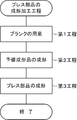
- FIG. 1 It is a flowchart which shows the process in the press molding of the press part by the molding method of the press part which concerns on one Embodiment of this invention. It is a perspective view which shows the outline of the external appearance structure of the blank used as the material before shape
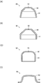
- (A) to (D) are cross-sectional views of a preformed product showing variations in the shape of the preformed product used in the method for molding a pressed part according to a modification of the present invention. It is sectional drawing which shows the shape of the press part which concerns on the modification of this invention.
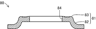
- FIG. 1 is a cross-sectional view showing a schematic configuration of a press part 80 formed by the press part forming method according to the present invention. Note that each drawing referred to in the present specification is schematically represented by exaggerating some of the components in order to facilitate understanding of the present invention. For this reason, the dimension, ratio, etc. between each component may differ.
- This press part 80 is a part used as a clutch guide, an end plate, a clutch piston, a plate carrier cup and the like constituting a clutch device mounted on a vehicle such as an automobile or a motorcycle, and a steel plate material (for example, SPCC, SPCD, SPCE, carbon steel such as S35C and high-tensile steel) are formed into a cylindrical shape.
- the pressed part 80 includes a product cylindrical part 82 in which the outer peripheral part of the body 81 formed in a cylindrical shape is tapered, and one end (the upper side in the figure) of the product cylindrical part 82.
- the portion is constituted by a corner portion 83 that is bent at a right angle toward the inside of the main body 81.
- a punch hole 84 made of a through hole is formed inside the corner portion 83 of the press part 80.
- the molding die 100 is a metal die that molds the pressed part 80 by pressing the preform 90.
- the preform 90 is a semi-processed product before the press part 80 is molded by the molding die 100, and is specifically formed in a bottomed cylindrical shape as shown in FIG.
- the preform 90 mainly includes a cylindrical portion 91 formed in a tapered shape, and an inclined portion 92 that is bent in an arc shape inward from an end portion on the small diameter side of the cylindrical portion 91 and extends in a planar shape.
- a positioning hole 93 made of a through hole is formed in the central portion of the flat portion of the inclined portion 92 of the preform 90.
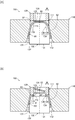
- the molding die 100 is mainly configured by a holding body 110, a piercing punch 120, and a piercing die 130 as shown in FIGS. 3 (A) and 3 (B).
- the holding body 110 is a die for forming the press part 80 in cooperation with the piercing punch 120 and the piercing die 130 while fixingly supporting the preform 90 in cooperation with the piercing die 130.
- Steel is formed in a substantially cylindrical shape. More specifically, the hold body 110 is configured by an outer extension restricting portion 111 and an outer fixed support portion 112 that form a through hole formed in the central portion.
- the outer stretch restricting portion 111 guides a piercing punch 120 described later, and an inclined portion 92 left uncut by an outer cutting edge 122 and an inner cutting blade 135 described later is provided on the radially outer side of the tubular portion 91. It is the cylindrical hole which comprises the wall body for preventing the plastic deformation to extend
- the outer stretch restricting portion 111 is formed with an inner diameter corresponding to the outer diameter of the corner portion 83 in the press part 80.
- the outer fixed support part 112 is a tapered hole for pressing and supporting the preformed product 90 together with the piercing die 130 by pressing the tubular part 91 of the preformed product 90 from the outer side of the tubular part 91. And is formed in a tapered shape corresponding to the tapered shape of the tubular portion 91 in the preform 90.
- the piercing punch 120 is a mold for forming the pressed part 80 by cutting and pressing the preform 90 in cooperation with the piercing die 130 and the holding body 110, and is made of die steel. It is formed in a cylindrical shape. More specifically, the piercing punch 120 has an outer diameter corresponding to the outer diameter of the corner portion 83 in the press part 80, in other words, an outer diameter that fits slidably into the outer extension regulating portion 111 in the hold body 110. And is formed to have an inner diameter corresponding to the inner diameter of the punch hole 84 formed inside the corner portion 83 of the press part 80.
- a pressing portion 121 is formed at the lower end of the piercing punch 120 that faces the piercing die 130.
- the pressing portion 121 is a portion for forming the corner portion 83 of the press part 80 by pressing the inclined portion 92 in the preform 90 toward the piercing die 130 and plastically deforming the shape, and the shape of the outer surface of the corner portion 83 is changed. It is formed in an inverted shape.
- the press part 121 is formed and formed in the convex shape corresponding to the corner
- An outer cutting edge 122 for forming the punch hole 84 of the press part 80 is formed by cutting the inclined portion 92 of the preform 90 at the inner end of the pressing portion 121 formed in the ring shape. Has been.
- the piercing die 130 cuts and presses the preform 90 in cooperation with the piercing punch 120 and the holding body 110 while fixingly supporting the preform 90 in cooperation with the holding body 110.
- This is a mold for forming the pressed part 80, and is formed by forming die steel in a substantially cylindrical shape. More specifically, the piercing die 130 is mainly composed of a die body 131 and a projecting body 134. Among these, the die body 131 is formed of a cylindrical body, and an inner fixed support portion 132 is formed at a tip portion of the cylindrical body on the side facing the piercing punch 120.
- the inner fixed support portion 132 is a portion for supporting the tubular portion 91 in the preform 90 from the inside of the tubular portion 91 and supporting the preform 90 in a fixed manner together with the hold body 110. It is formed in the taper shape corresponding to the taper shape of the cylindrical part 91 in the product 90.
- a protrusion 134 having a smaller diameter than the outer diameter of the tip surface is formed on the tip surface of the die body 131 facing the piercing punch 120, and a receiving portion 133 is provided outside the protrusion 134 on the tip surface. Is formed.
- the receiving portion 133 is a ring-shaped portion that receives the inclined portion 92 of the preform 90 pressed by the piercing punch 120 and plastically deforms the same portion, thereby forming the corner portion 83 of the pressed part 80.
- 83 is formed by reversing the shape of the inner side surface.
- the receiving portion 133 is formed in a planar shape corresponding to the planar shape of the inner surface of the corner portion 83 in the pressed part 80.
- the projecting body 134 is a portion for forming the corner portion 83 of the press part 80 by cutting the inclined portion 92 in the preform 90 and plastically deforming the inclined portion 92 left uncut by the cutting operation. It is formed in a cylindrical shape. More specifically, the projecting body 134 is configured such that an inner cutting edge 135 and an inner stretching regulating portion 136 are formed on the outer periphery thereof.
- the inner cutting edge 135 is a blade part for forming the punch hole 84 in the press part 80 by cutting the inclined part 92 in the preform 90 in cooperation with the outer cutting edge 122.
- the inner extension regulating portion 136 is a wall body for preventing the plastic deformation in which the inclined portion 92 left uncut by the outer cutting edge 122 and the inner cutting edge 135 extends inward in the radial direction of the cylindrical portion 91. That is, the width W of the molding space FS, which is a ring-shaped space between the outer extension restricting portion 111 of the hold body 110 and the inner extension restricting portion 136 of the protrusion 134, is the radial direction at the corner 83 of the press part 80. Corresponds to the width.
- a receiving support 137 is provided on the outer side of the die body 131 in the piercing die 130.
- the receiving support 137 is a mold that receives and supports the lower end portion of the cylindrical portion 91 in the preform 90 when the preform 90 is plastically deformed to form the pressed part 80.
- the receiving support 137 is formed in a ring shape that is fixedly fitted to the outer peripheral portion of the die body 131.
- the holding body 110, the piercing punch 120, and the piercing die 130 constituting the molding die 100 are attached to a press machine (not shown) for forming the press part 80 by pressing the preform 90. .
- the piercing die 130 including the receiver support 137 is fixedly provided on the press machine.
- the holding body 110 and the piercing punch 120 are provided in the press machine so as to be coaxial with the piercing die 130 and displaceable in a direction approaching and separating from the piercing die 130.
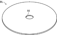
- the operator prepares a blank BL in the first step. Specifically, as shown in FIG. 5, the worker shows a steel plate (for example, carbon steel such as SPCC, SPCD, SPCE, S35C, etc. and high-strength steel) in a central portion of a flat plate formed in a circular shape.
- a blank BL is obtained by forming a positioning hole 93 for positioning using a non-punching press machine. Note that. Since the positioning hole 93 formed in the blank BL is used for positioning in the processing machine for press-molding the preform 90, it can be omitted when the positioning hole is not required in this processing machine (see FIG. 6 (D)).
- the worker forms the preform 90 in the second step.
- the preform 90 is a material that is molded into the pressed part 80 by the molding die 100, and is a half-process that is molded into a cup shape by drawing the blank BL. It is a product.
- the operator sets the blank BL in a drawing machine (not shown) provided with a preforming mold 200 as shown in FIG.
- the preforming die 200 is a die for forming the preformed product 90 by plastic processing a flat blank BL, and is mainly composed of a preforming punch 210, a preforming die 220, and an eject pin 230.
- the preforming punch 210 is a mold for forming the cylindrical portion 91 and the inclined portion 92 by pressing the central portion of the blank BL.
- the preforming punch 210 includes a part formed in a tapered shape corresponding to the cylindrical part 91 in the preformed product 90 and a part formed in an arc shape corresponding to the inclined part 92 at the tip of the part. It is configured.
- the preforming die 220 is a mold for molding the cylindrical portion 91 and the inclined portion 92 while supporting the blank BL that is disposed opposite to the preforming punch 210 and pressed by the preforming punch 210. .
- the preforming die 220 includes a through-hole formed in a tapered shape corresponding to the tubular portion 91 in order to receive the blank BL pressed by the preforming punch 210 and form the tubular portion 91.
- the eject pin 230 is a cylindrical mold for extruding the preform 90 in which the cylindrical portion 91 and the inclined portion 92 are respectively molded from the preforming die 220.
- the operator forms the preform 90 by setting the blank BL in the preforming mold 200 and operating a drawing machine (not shown). Thereby, the operator can obtain the cup-shaped preform 90 which shape
- the preform 90 can be molded while suppressing a decrease in the plate thickness of the cylindrical portion 91 and the inclined portion 92 by forming the inclined portion 91 in an arc shape.
- the worker forms the pressed part 80 in the third step.
- the operator sets the preform 90 molded in the second step in the molding die 100 and operates a press machine (not shown). Press processing to the preform 90 is started.
- the worker arranges the preform 90 so as to cover the protrusion 134 in the piercing die 130.
- the press part 80 is formed by the press machine starting movement of the holding body 110 and the piercing punch 120 toward the piercing die 130 as shown in FIGS. This is performed through the steps 1 and 2.
- Substep 1 First, the molding die 100 cuts the inner portion of the inclined portion 92 with respect to the preform 90. Specifically, as shown in FIG. 3A, in the molding die 100, the holding body 110 moves to the piercing die 130 side, and the outer fixed support portion 112 presses the cylindrical portion 91 in the preform 90. By doing so, the cylindrical portion 91 is fixedly supported by being sandwiched between the outer fixed support portion 112 and the inner fixed support portion 132 of the piercing die 130. Next, in the molding die 100, the piercing punch 120 moves toward the piercing die 130, whereby the pressing portion 121 presses the inclined portion 92 in the preform 90 and the outer cutting edge 122 and the inner cutting edge 135 in the piercing die 130. And the inclined portion 92 is cut. Thereby, as for the preform 90, the inner part including the positioning hole 93 in the inclined part 92 is cut out circularly.
- Substep 2 Next, the molding die 100 forms the corner portion 83 by plastic processing the inclined portion 92 with respect to the preform 90. Specifically, as shown in FIG. 3B, the molding die 100 further advances the piercing punch 120 toward the piercing die 130 after cutting away a part of the inclined portion 92 in the preform 90. The inclined portion 92 left uncut by the step is inclined toward the receiving portion 133 in the molding space FS surrounded by the holding body 110, the piercing punch 120, and the piercing die 130, and then compressed.
- the inclined portion 92 left uncut by the sub-step 1 is formed to bend and extend, it is between the outer extension restricting portion 111 of the holding body 110 and the inner extension restricting portion 136 of the protrusion 134.
- the plastic deformation is regulated by the outer stretch regulation part 111 and the inner stretch regulation part 136 in the width direction in the molding space FS.
- the thickness increases, that is, the wall thickness increases as it is pressed toward the 133 side. Therefore, in the inclined portion 92 in the preform 90, the corner portion 83 is formed in a state where the thickness is increased, and the punch hole 84 is formed on the radially inner side of the corner portion 83.
- the corner 83 is formed to be thicker than the blank BL and the cylindrical portion 91 (later product cylindrical portion 82) including the horizontal portion around the punch hole 84.
- the corner portion 83 Since the corner portion 83 is compressed after the inclined portion 92 is tilted, the corner portion 83 is formed while increasing the thickness with a small force compared to the conventional technique in which the material is formed only by compression all the time. be able to. In addition, since the corner portion 83 is pressed while the inclined portion 92 is tilted, the corner portion 83 can be accurately formed without causing entanglement of the portion.
- the receiving support 137 disposed outside the piercing die 130 is the cylinder of the preform 90 during the cutting process of the inclined portion 92 in the sub-step 1 and the molding process of the corner portion 83 in the sub-step 2. The lower end of the figure 91 in the figure is supported.
- the press part 80 is formed by the cutting process of the inclined portion 92 by the sub-step 1 and the forming process of the corner portion 83 by the sub-step 2. That is, the cutting process of the inclined portion 92 by the sub step 1 and the forming process of the corner portion 83 by the sub step 2 correspond to the corner forming process according to the present invention. Therefore, the press machine moves the piercing punch 120 and the holding body 110 away from the piercing die 130 after the forming process of the corner 83, thereby opening the molding die 100, that is, molding. The pressed part 80 is brought into a state where it can be removed from the molding die 100. Thereby, the operator finishes the molding work of the press part 80 by taking out the press part 80 from the opened molding die 100.
- the method of forming a pressed part is the cylindrical portion 91 formed in a cylindrical shape and the cylindrical portion 91 on the distal end side of the cylindrical portion 91.
- a part of the inclined part 92 is cut with respect to the preform 90 having the inclined parts 92 inclined from each other, and a part left by the cutting is pushed down toward the piercing die 130 in the molding space FS and then compressed.
- the corner 83 is formed. That is, in the method for forming a pressed part according to the present invention, the forming portion (inclined portion 92) of the corner portion 83 in the preform 90 is not crushed and plastically deformed while buckling the same portion.
- the molding die 100 is configured to mold the press part 80 as a finished product by performing cutting and plastic working on the preform 90.
- the molding die 100 molds the press part 80, which is a semi-processed product just before completion, which is completed as the press part 80 by performing a finishing process by performing a cutting process and a plastic process on the preform 90. You may make it do.
- the operator completes the press part 80 by performing a finish molding process using a finishing die (not shown) or the like on the press part 80 that is a semi-processed product immediately before completion.
- the inclined portion 92 in the preform 90 is formed in a shape that smoothly curves from the cylindrical portion 91 into an arc shape.
- the inclined portion 92 in the preform 90 is formed so as to extend in a direction intersecting with the width W so as to be longer than the width W of the molding space FS after the cutting of the inclined portion 92, that is, extending in an inclined manner.
- the present invention is not necessarily limited to the above embodiment. Therefore, the inclined portion 92 in the preform 90 can be formed to extend linearly in an inclined state as shown in FIGS. 6 (A) and 6 (B), for example.
- the cylindrical portion 91 in the preform 90 is formed in a tapered shape that tapers toward the inclined portion 92 side.
- the cylindrical part 91 in the preform 90 need only be formed in a cylindrical shape, and is not necessarily limited to the above embodiment. Therefore, the cylindrical part 91 in the preform 90 can also be formed in a cylindrical shape with a constant outer diameter, as shown in FIGS. 6B and 6C, for example.
- the molding die 100 may be configured to sandwich the cylindrical portion 91 in the preform 90 from the radial direction of the cylindrical portion 91.
- the cylindrical portion 91 can be formed in a so-called trumpet shape in which the end portion opposite to the inclined portion 92 extends in an arc shape.
- the press part 80 formed by the preformed product 90 has a trumpet shape in which the end portion on the opposite side of the corner portion 83 of the product cylindrical portion 82 spreads in an arc shape. It can also be formed into.
- the piercing die 130 in the molding die 100 cuts the die body 131 that fixedly supports the cylindrical portion 91 in the preform 90 and the inclined portion 92 in the preform 90.
- the protrusion 134 was integrally provided.
- the piercing die 130 includes a die body 131 that fixedly supports the cylindrical portion 91 in the preform 90 and a protrusion 134 that cuts the inclined portion 92 in the preform 90 as separate bodies. It can also be configured.
- the piercing die 130 may be configured such that the die body 131 is formed in a cylindrical shape having a through hole, and the projecting body 134 is slidably fitted into a through hole formed in the die body 131.
- the molding die 100 includes the piercing die 130 including the receiver support 137 fixed to the press machine, and the holding body 110 and the piercing punch 120 with respect to the piercing die 130. It is provided movably. However, since the movement of the holding body 110 and the piercing punch 120 relative to the piercing die 130 is relative, it is natural that either of them may be the moving side and the fixed side. For example, the piercing die 130 including the receiver support 137 may move with respect to the holding body 110 and the piercing punch 120.
- the press part 80 is assumed to be a part used as a clutch guide, an end plate, a clutch piston plate carrier cup, and the like constituting a clutch device mounted on a vehicle such as an automobile or a motorcycle.
- parts other than these may be used. That is, the method for forming a press part according to the present invention can be widely applied to a metal press part 80 having a corner 83 bent at one end of a cylindrical body.
- the press part 80 is not limited to a cylindrical shape, and may be a so-called irregular shape such as an ellipse other than a circle or a polygon such as a triangle or a square.
- the hole 84 in the press part 80 is formed in a circular shape.
- the shape of the punch hole 84 in the press part 80 is appropriately determined according to the specifications of the press part 80, and is not limited to the above embodiment. That is, the punching hole 84 in the press part 80 is formed into a shape other than a circle, for example, an ellipse, a polygon such as a triangle or a quadrangle, a gear shape and a spline shape alone or a modified shape appropriately combining them. Can do.
- the material constituting the press part 80 can be a metal material other than a steel plate particularly suitable for drawing such as SPCC, SPCD and SPCE.
- high carbon steel and high strength steel that are generally not suitable for drawing or burring can be formed with high accuracy without causing molding defects such as cracks and cracks.
- Protruding body 135 ... Inner cutting edge, 136 ... Inner extending
- stretching control part 137 ...
- Receiving support body 200 ... mold, 210 ... preforming punch, 220 ... preforming die, 230 ... ejector pin.
Landscapes
- Engineering & Computer Science (AREA)
- Mechanical Engineering (AREA)
- Shaping Metal By Deep-Drawing, Or The Like (AREA)
Abstract
Description
次に、本発明に係るプレス部品の成形方法によってプレス部品80をプレス成形するための成形金型100について説明する。この成形金型100は、予備成形品90にプレス加工を行うことによりプレス部品80を成形する金属製の型である。この場合、予備成形品90は、成形金型100によってプレス部品80を成形する前の半加工品であり、詳しくは図2に示すように、有底筒状に形成されている。この予備成形品90は、主として、テーパ状に形成された筒状部91とこの筒状部91における小径側の端部から内側に円弧状に屈曲した後平面状に延びる傾斜部92とで構成されている。また、予備成形品90の傾斜部92における平面状に延びた部分の中央部には、貫通孔からなる位置決め孔93が形成されている。
次に、上記のように構成した成形金型100を用いたプレス部品の成形方法の作動について図4に示す工程流れ図を参照しながら説明する。まず、作業者は、第1工程にて、ブランクBLを用意する。具体的には、作業者は、図5に示すように、鋼板(例えば、SPCC,SPCD、SPCE、S35Cなどの炭素鋼および高張力鋼など)材を円形状に形成した平板の中央部に図示しない打抜きプレス加工機を用いて位置決め用の位置決め孔93を成形してブランクBLを得る。なお。ブランクBLに形成した位置決め孔93は、予備成形品90をプレス成形する加工機において位置決めに用いるものであるため、この加工機において位置決め用の孔が不要の場合には省略することができる(図6(D)参照)。
プレートキャリア用カップおよびなどとして用いられる部品を想定したが、これら以外の部品であってもよい。すなわち、本発明に係るプレス部品の成形方法は、筒状体の一方の端部に屈曲した角部83を有する金属製のプレス部品80に広く適用することができる。この場合、プレス部品80は、円筒形状に限らず、円以外の楕円、三角や四角などの多角形状などの所謂異形状であってもよい。
80…プレス部品、81…本体、82…製品筒状部、83…角部、84…抜き孔、
90…プレス部品、91…筒状部、92…傾斜部、93…位置決め孔、
100…成形金型、
110…ホールド体、111…外側延伸規制部、112…外側固定支持部、
120…ピアスパンチ、121…押圧部、122…外側切れ刃、
130…ピアスダイス、131…ダイス本体、132…内側固定支持部、133…受け部、134…突出体、135…内側切れ刃、136…内側延伸規制部、137…受け支持体、
200…金型、210…予備成形パンチ、220…予備成形ダイス、230…イジェクタピン。
Claims (5)
- 筒状体の一方の端部が内側に屈曲してカップ状に形成された金属製のプレス部品の成形方法であって、
筒状に成形された筒状部および同筒状部の先端部側に同筒状部から傾斜する傾斜部をそれぞれ有する予備成形品と、
前記予備成形品における前記傾斜部の外側に配置されて同予備成形品における前記傾斜部の一部を切断するための外側切れ刃および同外側切れ刃によって切り残された部分を押圧する押圧部をそれぞれ有するピアスパンチと、
前記予備成形品における前記傾斜部の内側に配置されて前記外側切れ刃と協働して前記傾斜部の一部を切断するための内側切れ刃、前記傾斜部との間に成形空間を介して前記押圧部によって押圧される前記傾斜部を受ける受け部、前記押圧部によって押圧される前記傾斜部の長さ方向の延伸を規制する内側延伸規制部および前記筒状部を固定的に支持するための内側固定支持部をそれぞれ有したピアスダイスと、
前記予備成形品における前記傾斜部の外側に配置されて前記押圧部によって押圧される前記傾斜部の長さ方向の延伸を規制する外側延伸規制部および前記傾斜部を固定的に支持する外側固定支持部をそれぞれ有したホールド体とをそれぞれ用意しておき、
前記ピアスダイスと前記ホールド体とで前記予備成形品を固定支持した状態で前記ピアスパンチと前記ピアスダイスとを相対変位させることによって前記傾斜部の一部を切断するとともに前記切断による前記切り残された部分を傾倒させた後押圧することによって前記角部を成形する角部成形工程を含むことを特徴とするプレス部品の成形方法。 - 請求項1に記載したプレス部品の成形方法において、
前記予備成形品は、
前記傾斜部が前記筒状部から滑らかに円弧状に湾曲して形成されていることを特徴とするプレス部品の形成方法。 - 請求項1または請求項2に記載したプレス部品の成形方法において、
前記予備成形品は、
前記筒状部が先細りのテーパ状に形成されていることを特徴とするプレス部品の形成方法。 - 筒状体の一方の端部が内側に屈曲してカップ状に形成された金属製のプレス部品の製造方法であって、
筒状に成形された筒状部および同筒状部の先端部側に同筒状部から傾斜する傾斜部をそれぞれ有する予備成形品と、
前記予備成形品における前記傾斜部の外側に配置されて同予備成形品における前記傾斜部の一部を切断するための外側切れ刃および同外側切れ刃によって切り残された部分を押圧する押圧部をそれぞれ有するピアスパンチと、
前記予備成形品における前記傾斜部の内側に配置されて前記外側切れ刃と協働して前記傾斜部の一部を切断するための内側切れ刃、前記傾斜部との間に成形空間を介して前記押圧部によって押圧される前記傾斜部を受ける受け部、前記押圧部によって押圧される前記傾斜部の長さ方向の延伸を規制する内側延伸規制部および前記筒状部を固定的に支持するための内側固定支持部をそれぞれ有したピアスダイスと、
前記予備成形品における前記傾斜部の外側に配置されて前記押圧部によって押圧される前記傾斜部の長さ方向の延伸を規制する外側延伸規制部および前記傾斜部を固定的に支持する外側固定支持部をそれぞれ有したホールド体とをそれぞれ用意しておき、
前記ピアスダイスと前記ホールド体とで前記予備成形品を固定支持した状態で前記ピアスパンチと前記ピアスダイスとを相対変位させることによって前記傾斜部の一部を切断するとともに前記切断による前記切り残された部分を傾倒させた後押圧することによって前記角部を成形する角部成形工程を含むことを特徴とするプレス部品の製造方法。 - 筒状体の一方の端部が内側に屈曲してカップ状に形成された金属製のプレス部品の成形用金型であって、
筒状に成形された筒状部および同筒状部の先端部側に同筒状部から傾斜する傾斜部をそれぞれ有する予備成形品における前記傾斜部の外側に配置されて同予備成形品における前記傾斜部の一部を切断するための外側切れ刃および同外側切れ刃によって切り残された部分を押圧する押圧部をそれぞれ有するピアスパンチと、
前記予備成形品における前記傾斜部の内側に配置されて前記外側切れ刃と協働して前記傾斜部の一部を切断するための内側切れ刃、前記傾斜部との間に成形空間を介して前記押圧部によって押圧される前記傾斜部を受ける受け部、前記押圧部によって押圧される前記傾斜部の長さ方向の延伸を規制する内側延伸規制部および前記筒状部を固定的に支持するための内側固定支持部をそれぞれ有したピアスダイスと、
前記予備成形品における前記傾斜部の外側に配置されて前記押圧部によって押圧される前記傾斜部の長さ方向の延伸を規制する外側延伸規制部および前記傾斜部を固定的に支持する外側固定支持部をそれぞれ有したホールド体とを備えることを特徴とするプレス部品の成形金型。
Priority Applications (2)
| Application Number | Priority Date | Filing Date | Title |
|---|---|---|---|
| KR1020157008799A KR102182154B1 (ko) | 2013-01-11 | 2013-12-19 | 프레스 부품의 성형 방법, 프레스 부품의 제조 방법 및 프레스 부품의 성형용 금형 |
| US14/759,833 US10086423B2 (en) | 2013-01-11 | 2013-12-19 | Method for forming a pressed component |
Applications Claiming Priority (2)
| Application Number | Priority Date | Filing Date | Title |
|---|---|---|---|
| JP2013-004112 | 2013-01-11 | ||
| JP2013004112A JP6051052B2 (ja) | 2013-01-11 | 2013-01-11 | プレス部品の成形方法、プレス部品の製造方法およびプレス部品の成形用金型 |
Publications (1)
| Publication Number | Publication Date |
|---|---|
| WO2014109201A1 true WO2014109201A1 (ja) | 2014-07-17 |
Family
ID=51166860
Family Applications (1)
| Application Number | Title | Priority Date | Filing Date |
|---|---|---|---|
| PCT/JP2013/084105 Ceased WO2014109201A1 (ja) | 2013-01-11 | 2013-12-19 | プレス部品の成形方法、プレス部品の製造方法およびプレス部品の成形用金型 |
Country Status (4)
| Country | Link |
|---|---|
| US (1) | US10086423B2 (ja) |
| JP (1) | JP6051052B2 (ja) |
| KR (1) | KR102182154B1 (ja) |
| WO (1) | WO2014109201A1 (ja) |
Cited By (2)
| Publication number | Priority date | Publication date | Assignee | Title |
|---|---|---|---|---|
| CN107442655A (zh) * | 2017-08-16 | 2017-12-08 | 无锡威唐工业技术股份有限公司 | 一种座椅侧板的加工模具 |
| JP7547990B2 (ja) | 2020-12-21 | 2024-09-10 | マツダ株式会社 | プレスによる穴開け加工方法 |
Families Citing this family (16)
| Publication number | Priority date | Publication date | Assignee | Title |
|---|---|---|---|---|
| JP2555471Y2 (ja) | 1996-06-21 | 1997-11-26 | 株式会社島津製作所 | 動釣合試験装置 |
| JP6051053B2 (ja) | 2013-01-11 | 2016-12-21 | 株式会社エフ・シー・シー | プレス部品の成形方法、プレス部品の製造方法およびプレス部品の成形用金型 |
| JP6051052B2 (ja) * | 2013-01-11 | 2016-12-21 | 株式会社エフ・シー・シー | プレス部品の成形方法、プレス部品の製造方法およびプレス部品の成形用金型 |
| JP6769100B2 (ja) * | 2016-05-11 | 2020-10-14 | 株式会社ジェイテクト | 等速ジョイントの外輪の製造方法 |
| US10220433B2 (en) * | 2016-11-16 | 2019-03-05 | Shiroki Corporation | Method of manufacturing door channel |
| CN106964692B (zh) * | 2017-04-20 | 2019-04-12 | 海宁汇豪太阳能科技有限公司 | 一种承压内胆的加工工艺及其加工装置 |
| CN107470416A (zh) * | 2017-08-23 | 2017-12-15 | 柳州市瑞安机械制造有限责任公司 | 一种抽风折弯装置 |
| CN107649549A (zh) * | 2017-08-23 | 2018-02-02 | 柳州市瑞安机械制造有限责任公司 | 一种摄像折弯装置 |
| CN107537899A (zh) * | 2017-08-23 | 2018-01-05 | 柳州市瑞安机械制造有限责任公司 | 一种冲压取件装置 |
| CN107350313A (zh) * | 2017-08-23 | 2017-11-17 | 柳州市瑞安机械制造有限责任公司 | 一种折弯装置 |
| CN107350319A (zh) * | 2017-08-23 | 2017-11-17 | 柳州市瑞安机械制造有限责任公司 | 一种加速折弯装置 |
| CN107597924A (zh) * | 2017-08-23 | 2018-01-19 | 柳州市瑞安机械制造有限责任公司 | 一种吹风折弯装置 |
| CN107442622A (zh) * | 2017-08-23 | 2017-12-08 | 柳州市瑞安机械制造有限责任公司 | 一种定位折弯装置 |
| CN110315296A (zh) * | 2019-07-25 | 2019-10-11 | 南京钢铁股份有限公司 | 一种弧形刀板的制备工艺 |
| CN114082840A (zh) * | 2021-11-24 | 2022-02-25 | 江苏华灿电讯集团股份有限公司 | 一种天线支座成型模具及其成型工艺 |
| JP7558394B2 (ja) * | 2021-12-06 | 2024-09-30 | 株式会社三五 | テーパ部を有する円筒体の成形方法 |
Citations (2)
| Publication number | Priority date | Publication date | Assignee | Title |
|---|---|---|---|---|
| JPH0732068A (ja) * | 1993-07-20 | 1995-02-03 | Yutaka Giken Co Ltd | ボス部形成方法 |
| JP2004358553A (ja) * | 2003-06-09 | 2004-12-24 | Koshin Giken:Kk | 厚肉縁付薄肉筒状製品の成形方法及び装置 |
Family Cites Families (9)
| Publication number | Priority date | Publication date | Assignee | Title |
|---|---|---|---|---|
| US2898788A (en) * | 1955-07-15 | 1959-08-11 | Wheeling Steel Corp | Apparatus for forming a boiler head or the like |
| JPS5351172A (en) * | 1976-10-21 | 1978-05-10 | Wako Kk | Method of fabricating flanged hollow products |
| JPS5732536A (en) * | 1980-08-01 | 1982-02-22 | Hitachi Ltd | Working method for electrode section of electron gun |
| JP2676303B2 (ja) | 1993-01-27 | 1997-11-12 | 株式会社ユタカ技研 | 増肉プレス加工方法 |
| CN1050075C (zh) * | 1993-06-30 | 2000-03-08 | 株式会社金光 | 板材制坯料的轮毂部形成方法及板材制皮带轮的形成方法 |
| CN1049373C (zh) * | 1993-08-30 | 2000-02-16 | 株式会社金光 | 金属板制旋转构件的制造方法 |
| JP4476913B2 (ja) * | 2004-12-13 | 2010-06-09 | ジヤトコ株式会社 | カップ状部材の成形方法及びその装置 |
| JP6051052B2 (ja) * | 2013-01-11 | 2016-12-21 | 株式会社エフ・シー・シー | プレス部品の成形方法、プレス部品の製造方法およびプレス部品の成形用金型 |
| JP6051053B2 (ja) | 2013-01-11 | 2016-12-21 | 株式会社エフ・シー・シー | プレス部品の成形方法、プレス部品の製造方法およびプレス部品の成形用金型 |
-
2013
- 2013-01-11 JP JP2013004112A patent/JP6051052B2/ja not_active Expired - Fee Related
- 2013-12-19 US US14/759,833 patent/US10086423B2/en not_active Expired - Fee Related
- 2013-12-19 KR KR1020157008799A patent/KR102182154B1/ko not_active Expired - Fee Related
- 2013-12-19 WO PCT/JP2013/084105 patent/WO2014109201A1/ja not_active Ceased
Patent Citations (2)
| Publication number | Priority date | Publication date | Assignee | Title |
|---|---|---|---|---|
| JPH0732068A (ja) * | 1993-07-20 | 1995-02-03 | Yutaka Giken Co Ltd | ボス部形成方法 |
| JP2004358553A (ja) * | 2003-06-09 | 2004-12-24 | Koshin Giken:Kk | 厚肉縁付薄肉筒状製品の成形方法及び装置 |
Cited By (3)
| Publication number | Priority date | Publication date | Assignee | Title |
|---|---|---|---|---|
| CN107442655A (zh) * | 2017-08-16 | 2017-12-08 | 无锡威唐工业技术股份有限公司 | 一种座椅侧板的加工模具 |
| CN107442655B (zh) * | 2017-08-16 | 2023-07-25 | 无锡威唐工业技术股份有限公司 | 一种座椅侧板的加工模具 |
| JP7547990B2 (ja) | 2020-12-21 | 2024-09-10 | マツダ株式会社 | プレスによる穴開け加工方法 |
Also Published As
| Publication number | Publication date |
|---|---|
| KR20150106394A (ko) | 2015-09-21 |
| US20150352622A1 (en) | 2015-12-10 |
| US10086423B2 (en) | 2018-10-02 |
| JP2014133260A (ja) | 2014-07-24 |
| JP6051052B2 (ja) | 2016-12-21 |
| KR102182154B1 (ko) | 2020-11-24 |
Similar Documents
| Publication | Publication Date | Title |
|---|---|---|
| JP6051052B2 (ja) | プレス部品の成形方法、プレス部品の製造方法およびプレス部品の成形用金型 | |
| JP5570081B2 (ja) | プレス部品の成形方法、プレス部品の製造方法およびプレス部品の成形用金型 | |
| JP6051053B2 (ja) | プレス部品の成形方法、プレス部品の製造方法およびプレス部品の成形用金型 | |
| US9707617B2 (en) | Press-forming method | |
| CN104736269B (zh) | 冲压加工方法及带底容器 | |
| KR20130115363A (ko) | 치형 부품의 제조 방법 및 치형 부품의 제조 장치 | |
| JP2010172916A (ja) | ワークの成形方法及び成形システム | |
| KR101473948B1 (ko) | 플랜지 구조체의 제조 방법 | |
| US20140298878A1 (en) | Method and system for metal drawing and redrawing | |
| JP4801187B2 (ja) | アンダーカット部の形成方法、部品の製造方法、及びプレス加工部品 | |
| US10974302B2 (en) | Manufacturing method for cylindrical portion | |
| JP5240510B2 (ja) | 絞り成形装置 | |
| US20090229432A1 (en) | Punching method using punch and punch for punching | |
| JP2019089078A (ja) | 歯車の鍛造方法 | |
| KR101714564B1 (ko) | 팁 제거용 프레스 펀치 | |
| CN103722109A (zh) | 横向锻造挤压 | |
| JP2006305600A (ja) | 傘歯車の鍛造成形方法及び装置 | |
| JP6976302B2 (ja) | 金属加工品の製造方法 | |
| JP2002307130A (ja) | リングギヤの製造方法及びそれに用いる装置 | |
| JPH09239482A (ja) | 円筒状部品の製造方法 | |
| RU2548865C9 (ru) | Способ изготовления осесимметричных полых изделий с отверстием в донной части | |
| JP2002137042A (ja) | 球面スパイダーの製造方法 | |
| JPS611441A (ja) | 中空金属円筒の製造方法 | |
| JP2005046871A (ja) | プレス成形方法及びプレス成形金型 |
Legal Events
| Date | Code | Title | Description |
|---|---|---|---|
| 121 | Ep: the epo has been informed by wipo that ep was designated in this application |
Ref document number: 13871182 Country of ref document: EP Kind code of ref document: A1 |
|
| ENP | Entry into the national phase |
Ref document number: 20157008799 Country of ref document: KR Kind code of ref document: A |
|
| WWE | Wipo information: entry into national phase |
Ref document number: 14759833 Country of ref document: US |
|
| NENP | Non-entry into the national phase |
Ref country code: DE |
|
| 122 | Ep: pct application non-entry in european phase |
Ref document number: 13871182 Country of ref document: EP Kind code of ref document: A1 |