WO2014104231A1 - 粘着層付き透明面材、積層体、表示装置、およびそれらの製造方法 - Google Patents
粘着層付き透明面材、積層体、表示装置、およびそれらの製造方法 Download PDFInfo
- Publication number
- WO2014104231A1 WO2014104231A1 PCT/JP2013/084968 JP2013084968W WO2014104231A1 WO 2014104231 A1 WO2014104231 A1 WO 2014104231A1 JP 2013084968 W JP2013084968 W JP 2013084968W WO 2014104231 A1 WO2014104231 A1 WO 2014104231A1
- Authority
- WO
- WIPO (PCT)
- Prior art keywords
- adhesive layer
- surface material
- weir
- curable
- oligomer
- Prior art date
Links
Images


Classifications
-
- C—CHEMISTRY; METALLURGY
- C09—DYES; PAINTS; POLISHES; NATURAL RESINS; ADHESIVES; COMPOSITIONS NOT OTHERWISE PROVIDED FOR; APPLICATIONS OF MATERIALS NOT OTHERWISE PROVIDED FOR
- C09J—ADHESIVES; NON-MECHANICAL ASPECTS OF ADHESIVE PROCESSES IN GENERAL; ADHESIVE PROCESSES NOT PROVIDED FOR ELSEWHERE; USE OF MATERIALS AS ADHESIVES
- C09J175/00—Adhesives based on polyureas or polyurethanes; Adhesives based on derivatives of such polymers
- C09J175/04—Polyurethanes
- C09J175/14—Polyurethanes having carbon-to-carbon unsaturated bonds
- C09J175/16—Polyurethanes having carbon-to-carbon unsaturated bonds having terminal carbon-to-carbon unsaturated bonds
-
- B—PERFORMING OPERATIONS; TRANSPORTING
- B32—LAYERED PRODUCTS
- B32B—LAYERED PRODUCTS, i.e. PRODUCTS BUILT-UP OF STRATA OF FLAT OR NON-FLAT, e.g. CELLULAR OR HONEYCOMB, FORM
- B32B27/00—Layered products comprising a layer of synthetic resin
- B32B27/06—Layered products comprising a layer of synthetic resin as the main or only constituent of a layer, which is next to another layer of the same or of a different material
- B32B27/08—Layered products comprising a layer of synthetic resin as the main or only constituent of a layer, which is next to another layer of the same or of a different material of synthetic resin
-
- B—PERFORMING OPERATIONS; TRANSPORTING
- B32—LAYERED PRODUCTS
- B32B—LAYERED PRODUCTS, i.e. PRODUCTS BUILT-UP OF STRATA OF FLAT OR NON-FLAT, e.g. CELLULAR OR HONEYCOMB, FORM
- B32B27/00—Layered products comprising a layer of synthetic resin
- B32B27/30—Layered products comprising a layer of synthetic resin comprising vinyl (co)polymers; comprising acrylic (co)polymers
- B32B27/308—Layered products comprising a layer of synthetic resin comprising vinyl (co)polymers; comprising acrylic (co)polymers comprising acrylic (co)polymers
-
- B—PERFORMING OPERATIONS; TRANSPORTING
- B32—LAYERED PRODUCTS
- B32B—LAYERED PRODUCTS, i.e. PRODUCTS BUILT-UP OF STRATA OF FLAT OR NON-FLAT, e.g. CELLULAR OR HONEYCOMB, FORM
- B32B27/00—Layered products comprising a layer of synthetic resin
- B32B27/40—Layered products comprising a layer of synthetic resin comprising polyurethanes
-
- B—PERFORMING OPERATIONS; TRANSPORTING
- B32—LAYERED PRODUCTS
- B32B—LAYERED PRODUCTS, i.e. PRODUCTS BUILT-UP OF STRATA OF FLAT OR NON-FLAT, e.g. CELLULAR OR HONEYCOMB, FORM
- B32B7/00—Layered products characterised by the relation between layers; Layered products characterised by the relative orientation of features between layers, or by the relative values of a measurable parameter between layers, i.e. products comprising layers having different physical, chemical or physicochemical properties; Layered products characterised by the interconnection of layers
- B32B7/04—Interconnection of layers
- B32B7/12—Interconnection of layers using interposed adhesives or interposed materials with bonding properties
-
- C—CHEMISTRY; METALLURGY
- C08—ORGANIC MACROMOLECULAR COMPOUNDS; THEIR PREPARATION OR CHEMICAL WORKING-UP; COMPOSITIONS BASED THEREON
- C08F—MACROMOLECULAR COMPOUNDS OBTAINED BY REACTIONS ONLY INVOLVING CARBON-TO-CARBON UNSATURATED BONDS
- C08F290/00—Macromolecular compounds obtained by polymerising monomers on to polymers modified by introduction of aliphatic unsaturated end or side groups
- C08F290/02—Macromolecular compounds obtained by polymerising monomers on to polymers modified by introduction of aliphatic unsaturated end or side groups on to polymers modified by introduction of unsaturated end groups
- C08F290/06—Polymers provided for in subclass C08G
- C08F290/067—Polyurethanes; Polyureas
-
- C—CHEMISTRY; METALLURGY
- C08—ORGANIC MACROMOLECULAR COMPOUNDS; THEIR PREPARATION OR CHEMICAL WORKING-UP; COMPOSITIONS BASED THEREON
- C08G—MACROMOLECULAR COMPOUNDS OBTAINED OTHERWISE THAN BY REACTIONS ONLY INVOLVING UNSATURATED CARBON-TO-CARBON BONDS
- C08G18/00—Polymeric products of isocyanates or isothiocyanates
- C08G18/06—Polymeric products of isocyanates or isothiocyanates with compounds having active hydrogen
- C08G18/28—Polymeric products of isocyanates or isothiocyanates with compounds having active hydrogen characterised by the compounds used containing active hydrogen
- C08G18/40—High-molecular-weight compounds
- C08G18/48—Polyethers
- C08G18/4833—Polyethers containing oxyethylene units
- C08G18/4837—Polyethers containing oxyethylene units and other oxyalkylene units
- C08G18/4841—Polyethers containing oxyethylene units and other oxyalkylene units containing oxyethylene end groups
-
- C—CHEMISTRY; METALLURGY
- C08—ORGANIC MACROMOLECULAR COMPOUNDS; THEIR PREPARATION OR CHEMICAL WORKING-UP; COMPOSITIONS BASED THEREON
- C08G—MACROMOLECULAR COMPOUNDS OBTAINED OTHERWISE THAN BY REACTIONS ONLY INVOLVING UNSATURATED CARBON-TO-CARBON BONDS
- C08G18/00—Polymeric products of isocyanates or isothiocyanates
- C08G18/06—Polymeric products of isocyanates or isothiocyanates with compounds having active hydrogen
- C08G18/70—Polymeric products of isocyanates or isothiocyanates with compounds having active hydrogen characterised by the isocyanates or isothiocyanates used
- C08G18/72—Polyisocyanates or polyisothiocyanates
- C08G18/74—Polyisocyanates or polyisothiocyanates cyclic
- C08G18/75—Polyisocyanates or polyisothiocyanates cyclic cycloaliphatic
- C08G18/751—Polyisocyanates or polyisothiocyanates cyclic cycloaliphatic containing only one cycloaliphatic ring
- C08G18/752—Polyisocyanates or polyisothiocyanates cyclic cycloaliphatic containing only one cycloaliphatic ring containing at least one isocyanate or isothiocyanate group linked to the cycloaliphatic ring by means of an aliphatic group
- C08G18/753—Polyisocyanates or polyisothiocyanates cyclic cycloaliphatic containing only one cycloaliphatic ring containing at least one isocyanate or isothiocyanate group linked to the cycloaliphatic ring by means of an aliphatic group containing one isocyanate or isothiocyanate group linked to the cycloaliphatic ring by means of an aliphatic group having a primary carbon atom next to the isocyanate or isothiocyanate group
- C08G18/755—Polyisocyanates or polyisothiocyanates cyclic cycloaliphatic containing only one cycloaliphatic ring containing at least one isocyanate or isothiocyanate group linked to the cycloaliphatic ring by means of an aliphatic group containing one isocyanate or isothiocyanate group linked to the cycloaliphatic ring by means of an aliphatic group having a primary carbon atom next to the isocyanate or isothiocyanate group and at least one isocyanate or isothiocyanate group linked to a secondary carbon atom of the cycloaliphatic ring, e.g. isophorone diisocyanate
-
- C—CHEMISTRY; METALLURGY
- C09—DYES; PAINTS; POLISHES; NATURAL RESINS; ADHESIVES; COMPOSITIONS NOT OTHERWISE PROVIDED FOR; APPLICATIONS OF MATERIALS NOT OTHERWISE PROVIDED FOR
- C09J—ADHESIVES; NON-MECHANICAL ASPECTS OF ADHESIVE PROCESSES IN GENERAL; ADHESIVE PROCESSES NOT PROVIDED FOR ELSEWHERE; USE OF MATERIALS AS ADHESIVES
- C09J7/00—Adhesives in the form of films or foils
- C09J7/30—Adhesives in the form of films or foils characterised by the adhesive composition
- C09J7/38—Pressure-sensitive adhesives [PSA]
- C09J7/381—Pressure-sensitive adhesives [PSA] based on macromolecular compounds obtained by reactions involving only carbon-to-carbon unsaturated bonds
- C09J7/385—Acrylic polymers
-
- B—PERFORMING OPERATIONS; TRANSPORTING
- B32—LAYERED PRODUCTS
- B32B—LAYERED PRODUCTS, i.e. PRODUCTS BUILT-UP OF STRATA OF FLAT OR NON-FLAT, e.g. CELLULAR OR HONEYCOMB, FORM
- B32B2307/00—Properties of the layers or laminate
- B32B2307/40—Properties of the layers or laminate having particular optical properties
- B32B2307/412—Transparent
-
- B—PERFORMING OPERATIONS; TRANSPORTING
- B32—LAYERED PRODUCTS
- B32B—LAYERED PRODUCTS, i.e. PRODUCTS BUILT-UP OF STRATA OF FLAT OR NON-FLAT, e.g. CELLULAR OR HONEYCOMB, FORM
- B32B2307/00—Properties of the layers or laminate
- B32B2307/50—Properties of the layers or laminate having particular mechanical properties
- B32B2307/542—Shear strength
-
- B—PERFORMING OPERATIONS; TRANSPORTING
- B32—LAYERED PRODUCTS
- B32B—LAYERED PRODUCTS, i.e. PRODUCTS BUILT-UP OF STRATA OF FLAT OR NON-FLAT, e.g. CELLULAR OR HONEYCOMB, FORM
- B32B2457/00—Electrical equipment
- B32B2457/20—Displays, e.g. liquid crystal displays, plasma displays
-
- C—CHEMISTRY; METALLURGY
- C08—ORGANIC MACROMOLECULAR COMPOUNDS; THEIR PREPARATION OR CHEMICAL WORKING-UP; COMPOSITIONS BASED THEREON
- C08G—MACROMOLECULAR COMPOUNDS OBTAINED OTHERWISE THAN BY REACTIONS ONLY INVOLVING UNSATURATED CARBON-TO-CARBON BONDS
- C08G2170/00—Compositions for adhesives
- C08G2170/40—Compositions for pressure-sensitive adhesives
Definitions
- the present invention relates to a transparent surface material with an adhesive layer, a laminate, a display device, and a method for producing them.
- a display device in which a display panel (bonded surface material) is protected by a protective plate (transparent surface material) a display device in which a display panel and a protective plate are bonded via an adhesive layer is known.
- a pressure-sensitive adhesive layer used in a laminate in which a pressure-sensitive adhesive layer is sandwiched between a pair of face materials such as the display device, a layered portion extending along the surface of the face material, and a weir-like portion surrounding the periphery of the layered portion There is proposed an adhesive layer made of a cured product of a curable resin composition in which the layered portion includes a curable compound and a non-curable oligomer (see Patent Documents 1 and 2).
- a manufacturing method of a laminated body like the said display apparatus there exist the following method (i) and (ii), for example.
- (I) After supplying a curable resin composition that forms a layered portion in a region surrounded by an uncured weir-like portion formed on the peripheral edge of the transparent face material surface, a protective film is applied in a reduced-pressure atmosphere. The attached support surface material is stacked, and returned to the atmospheric pressure atmosphere to cure the uncured dam-like portion and the layered portion, whereby an adhesive layer is formed on the transparent surface material, and the adhesive layer is covered with a protective film. A laminated body is obtained.
- the protective film of the laminate is peeled off at a desired time, and the laminate and the surface material to be bonded are stacked and bonded so that the pressure-sensitive adhesive layer is in contact with the surface material to be bonded under a reduced pressure atmosphere. Return this to atmospheric pressure.
- the transparent surface material is stacked in a reduced-pressure atmosphere. Then, the uncured weir portion and the layer portion are cured by returning to an atmospheric pressure atmosphere.
- the interface between the display panel and the adhesive layer Voids are formed in
- the volume of the void decreases due to the differential pressure between the pressure in the void (still reduced pressure) and the pressure applied to the adhesive layer (atmospheric pressure).
- the void disappears.
- the method (ii) even when voids are formed when the transparent face materials are stacked in a reduced pressure atmosphere, the voids disappear when returned to the atmospheric pressure atmosphere.
- the curable resin composition that forms the layered part contains a non-curable oligomer that does not participate in the curing reaction, the fluidity of the layered part formed compared to when the non-curable oligomer is not included. high. Therefore, the layered portion easily flows into the gap, and the gap generated at the interface between the adhesive layer and the face material disappears in a short time. Moreover, a layered part becomes low elasticity because non-curable oligomer is contained. Therefore, the stress applied to the display panel in contact with the adhesive layer is small, and display unevenness of the display device is suppressed.
- the non-curable oligomer diffuses from the layered portion of the adhesive layer to the weir-shaped portion, and the non-curable oligomer is near the interface between the weir-shaped portion and the layered portion. Since the difference between the thicknesses of the dam-like portion and the layer-like portion occurs due to the influence of the diffusion, there is a possibility that a gap may be generated between the surface to be bonded or a bonding failure may occur when bonding.
- the non-curable oligomer diffuses into the weir-shaped portion and the volume of the weir-shaped portion increases. There is a risk that defects or voids in the surface to be bonded will occur.
- the present invention provides a transparent surface material with a pressure-sensitive adhesive layer, a display device, and a laminate that hardly cause defects in the layered portion and the weir-shaped portion even after a predetermined time has elapsed.
- the present invention provides a transparent surface material with a pressure-sensitive adhesive layer and a method for manufacturing a display device, in which defects do not easily occur in a layered portion and a weir-shaped portion even after a predetermined time has elapsed.
- the transparent surface material with an adhesive layer of the present invention has a transparent surface material and an adhesive layer formed on at least one surface of the transparent surface material, and the adhesive layer is along the surface of the transparent surface material. And a weir-like portion surrounding the periphery of the layer-like portion, the weir-like portion containing the following curable compound (I ′) and the following non-curable oligomer (II ′)
- Curable compound (I ′) A urethane acrylate oligomer (A ′) and a monomer (B ′) having a molecular weight of less than 600 and having one or more curable functional groups.
- Non-curable oligomer (II) has a hydroxyl group that does not undergo a curing reaction with the curable compound (I) at the time of curing of both the curable resin composition for forming a layered portion and the curable resin composition for forming a weir-shaped portion Oligomer.
- the urethane acrylate oligomers (A) and (A ′) are preferably urethane acrylate oligomers synthesized using polyoxyalkylene polyol and polyisocyanate as raw materials.
- the non-curable oligomers (II) and (II ′) are preferably polyoxyalkylene polyols.
- the number average molecular weight per hydroxyl group of the non-curable oligomers (II) and (II ′) is preferably 400 to 8000.
- the number average molecular weight of the urethane acrylate oligomer (A) is preferably 1000 to 100,000. It is preferable that the curable resin composition for forming a layered portion includes a photopolymerization initiator (C1), and the curable resin composition for forming a weir-shaped portion includes a photopolymerization initiator (C2).
- the storage shear elastic modulus at 35 ° C. of the weir-shaped part is preferably not less than 15 times and not more than 15 times the storage shear elastic modulus of the layered part at 35 ° C.
- the weir-like portion preferably has a storage shear modulus at 35 ° C. of 1 to 150 kPa.
- the layered portion preferably has a storage shear modulus at 35 ° C. of 1 to 100 kPa.
- the transparent surface material in the transparent surface material with the pressure-sensitive adhesive layer of the present invention includes a light-shielding printing portion formed on the peripheral edge of the surface, and at least a part of the layered portion and the weir-shaped portion is the surface of the transparent surface material. In the in-plane direction, it is preferable to be located inside the light-shielding print portion.
- the weir-like portion preferably contains a cured product made of an oligomer having a number average molecular weight of 30,000 to 100,000.
- the weir-like portion preferably contains a cured product made of a monomer having a molecular weight of 125 to 600 and containing no acid group.
- the weir-like portion preferably has an uncured viscosity of 40 Pa ⁇ s to 100 Pa ⁇ s.
- the transparent face material with an adhesive layer of the present invention may further have a peelable protective film that covers at least a part of the surface of the adhesive layer.
- the method for producing the transparent surface material with an adhesive layer of the present invention having the protective film is a method having the following steps (a) to (e).
- the display apparatus of this invention has a display panel and the transparent surface material with the adhesion layer of this invention bonded together by the display panel so that an adhesion layer may contact
- the manufacturing method of the display device of the present invention is a method in which a display panel and a transparent surface material with an adhesive layer are stacked and bonded so that the adhesive layer is in contact with the display panel in a reduced pressure atmosphere of 10 kPa or less.
- the laminated body of this invention is a laminated body by which the transparent surface material with the adhesion layer of this invention and the to-be-bonded surface material were bonded.
- the transparent face material with an adhesive layer of the present invention If used, it is difficult for defects to occur in the layered portion and the weir-shaped portion even after a predetermined time has elapsed.
- a transparent surface material with an adhesive layer that hardly causes defects in the layered portion and the weir-shaped portion can be obtained even after a predetermined time has elapsed.
- the display device of the present invention is less likely to cause defects in the layered portion and the weir-shaped portion even after a predetermined time has elapsed.
- the display device manufacturing method of the present invention it is possible to obtain a display device in which defects are hardly generated in the layered portion and the weir-shaped portion even after a predetermined time has elapsed.
- the laminated body of the present invention is less likely to cause defects in the layered portion and the weir-shaped portion even after a predetermined time has elapsed.
- transparent means that the whole or a part of the display image of the display panel is optically distorted after the face material and the display surface of the display panel are bonded through the adhesive layer without any gap. It means an aspect that can be seen through the face material without receiving it. Therefore, even if part of the light incident on the face material from the display panel is absorbed and reflected by the face material, or the visible material has a low visible ray transmittance due to a change in optical phase, etc. If the display image on the display panel can be visually recognized without optical distortion through the material, it can be said to be “transparent”.
- the transparent surface material includes a surface material having a polarizing plate.
- curable functional group means a functional group having a radical polymerizable unsaturated bond.
- (Meth) acrylate means acrylate or methacrylate.
- the “average thickness” in the present specification is an average value of thicknesses measured at 10 locations.
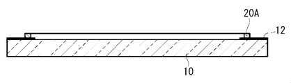
- FIG. 1 is a cross-sectional view showing an example of a transparent surface material with an adhesive layer of the present invention.
- the transparent surface material 1 with an adhesive layer having the protective film 16 includes a transparent surface material 10, a light shielding printing portion 12 formed on the peripheral edge of the surface of the transparent surface material 10, and a transparent surface on which the light shielding printing portion 12 is formed. It has the adhesion layer 14 formed in the surface of the face material 10, and the peelable protective film 16 which covers the surface of the adhesion layer 14.
- the transparent surface material 1 with an adhesive layer shown in FIG. 1 can manufacture a display apparatus by peeling off the protective film 16 and then bonding to the display panel.
- FIG. 1 illustrates the case where the adhesive layer 14 is formed on one side of the transparent surface material 10, the adhesive layer 14 may be formed on both surfaces of the transparent surface material 10.
- the surface of the adhesive layer 14 is also covered with a peelable protective film 16.
- the transparent surface material 10 is preferably a protective plate that is provided on the image display side of the display panel described later and protects the display panel.
- Examples of the transparent face material 10 include a glass plate or a transparent resin plate.
- the transparent surface material 10 has not only high transparency with respect to light emitted from the display panel and reflected light, but also light resistance, low birefringence, high planar accuracy, surface scratch resistance, and high mechanical strength.
- the glass plate is most preferable from the viewpoint of having it.
- it is preferable that the transparent surface material 10 is a glass plate also from the point which permeate
- the material for the glass plate examples include glass materials such as soda lime glass.
- a high transmission glass (white plate glass) having a lower iron content and less bluishness is preferable.
- tempered glass may be used to enhance safety.
- a thin glass plate it is preferable to use a chemically strengthened glass plate.
- the material for the transparent resin plate include highly transparent resin materials (such as polycarbonate and polymethyl methacrylate).
- the transparent face material 10 may be subjected to a surface treatment in order to improve the interfacial adhesive force with the adhesive layer 14.
- a surface treatment method include a method of treating the surface of the transparent face material 10 with a silane coupling agent, a method of forming a silicon oxide thin film by an oxidation flame using a frame burner, and the like.
- the transparent surface material 10 may be provided with an antireflection layer on the surface opposite to the side on which the adhesive layer 14 is formed.
- Examples of the method of providing the antireflection layer include a method of directly forming an inorganic thin film on the surface of the transparent surface material 10, a method of bonding a transparent resin film provided with the antireflection layer to the protective plate 10, and the like. Further, depending on the purpose, a part or the whole of the transparent face material 10 is colored, or a part or the whole of the surface of the transparent face material 10 is polished to form a glass to scatter light, or the surface of the transparent face material 10 is scattered. Further, a minute unevenness or the like may be formed on a part or the whole of the light to refract or reflect the transmitted light. Further, a colored film, a light scattering film, a photorefractive film, a light reflecting film, or the like may be attached to a part or the whole of the surface of the transparent surface material 10.
- the shape of the transparent face material 10 is usually rectangular for the purpose of matching the outer shape of the display device.
- a protective plate that covers the entire display surface of the display panel and has a curved shape in the outer shape can be used. What is necessary is just to set the magnitude
- the size of the transparent surface material 10 is suitably 0.5 m ⁇ 0.4 m or more, and particularly preferably 0.7 m ⁇ 0.4 m or more.
- the upper limit of the size of the transparent surface material 10 is often determined by the size of the display panel. Also, a display device that is too large is likely to be difficult to handle during installation.
- the upper limit of the size of the transparent face material 10 is usually about 2.5 m ⁇ 1.5 m due to these restrictions.
- the thickness of the transparent face material 10 is preferably 0.5 to 25 mm in the case of a glass plate.
- the thickness of the glass is preferably about 0.5 to 1.5 mm in terms of strength.
- the thickness of the transparent resin plate is preferably 2 to 10 mm.
- the light-shielding printing unit 12 hides wiring members and the like connected to the display panel so that areas other than the image display area of the display panel, which will be described later, are not visible from the transparent surface material 10 side.
- the light-shielding printing unit 12 can be formed on the surface on which the adhesive layer 14 is formed or on the opposite surface. In terms of reducing the parallax between the light shielding printing unit 12 and the image display area, it is preferable to form the light shielding printing unit 12 on the surface on the side where the adhesive layer 14 is formed.
- the transparent face material 10 is a glass plate, it is preferable to use ceramic printing containing a black pigment for the light shielding printing portion 12 because of high light shielding properties.
- the light-shielding printing part can also be formed by bonding a transparent film provided with the light-shielding printing part in advance to the protective plate.
- a light shielding printing portion may be provided on the peripheral edge of the transparent film on the surface to be bonded to the protective plate, and a film having an antireflection layer on the back surface thereof, that is, the outermost surface of the display device may be bonded to the protective plate.
- the display panel wiring member has a structure that cannot be seen from the display panel viewing side, or is concealed by another member such as a housing of the display device, or adheres to the bonded surface material other than the display panel
- the light shielding printing portion 12 may not be formed on the transparent face material 10.
- the pressure-sensitive adhesive layer 14 includes a layered portion 18 that extends along the surface of the transparent face material 10, and a weir-shaped portion 20 that touches and surrounds the periphery of the layered portion 18.
- the layered portion 18 is a portion made of a cured product (transparent resin) formed by curing a curable resin composition for forming a layered portion (hereinafter sometimes referred to as “first composition”).
- the weir-shaped portion 20 is formed of a cured product (transparent resin) formed by applying and curing a curable resin composition for forming a weir-shaped portion (hereinafter also referred to as “second composition”). Part.
- the transparent face material 1 with the adhesive layer is composed of a content W1 expressed by mass% of the non-curable oligomer (II) in the layered portion 18 described later and the non-curable oligomer (II ′) in the weir-shaped portion 20.
- the difference (W1 ⁇ W2) from the content W2 expressed in mass% is 40 or less. If the difference (W1-W2) is 40 or less, the difference between the content of the non-curable oligomer (II) in the layered portion and the content of the non-curable oligomer (II ′) in the weir-shaped portion is small.
- the difference (W1-W2) is 40 or less, preferably 30 or less, more preferably 10 or less, and particularly preferably 5 or less. Further, (W1-W2) is preferably more than 0 (that is, W1> W2).
- the measurement of the content W1 of the non-curable oligomer (II) in the layered portion is performed in a region 2 cm or more away from the outermost peripheral portion of the nearest weir-shaped portion in the layered portion. Do. Further, the measurement of the content W2 of the non-curable oligomer (II ′) in the weir-shaped portion is performed in a region separated from the outermost peripheral portion of the weir-shaped portion by a distance half the height of the weir-shaped portion.
- the measurement location in the layered portion As the region, it is possible to eliminate the influence of diffusion of the non-curable oligomer (II) in the vicinity of the interface between the layered portion and the weir-shaped portion. Moreover, even if the outermost peripheral part of a dam-like part touches external air and it becomes inadequate hardening by making the measurement location in a dam-like part into the said area
- the first composition forming the layered portion 18 may be a photocurable resin composition or a thermosetting resin composition.
- the layered portion 18 is preferably a cured product of a photocurable resin composition containing a curable compound and a photopolymerization initiator (C1) because it can be cured at a low temperature and has a high curing rate.
- C1 photopolymerization initiator
- the first photocurable composition is a composition containing a curable compound (I), a non-curable oligomer (II), and a photopolymerization initiator (C1). Moreover, a 1st composition may also contain an additive as needed.
- the first composition preferably has a viscosity at 25 ° C. of 0.05 Pa ⁇ s or more and a viscosity at 40 ° C. of 50 Pa ⁇ s or less, a viscosity at 25 ° C. of 0.2 Pa ⁇ s or more and 40 ° C. More preferably, the viscosity is 10 Pa ⁇ s or less. If the viscosity at 25 ° C.
- the coating shape of the first composition that becomes the layered portion is maintained until the lamination, and after the lamination
- the pressure difference between the pressure in the void (still reduced pressure) and the pressure applied to the adhesive layer (atmospheric pressure) is returned to the atmospheric pressure atmosphere. Since it is easy, a cured film without remaining bubbles can be obtained. If the viscosity at 40 ° C.
- the viscosity of the first composition is measured using an E-type viscometer.
- the viscosity of the first composition can be adjusted by the molecular weight and content ratio of the non-curable oligomer (II). Moreover, it can adjust also by adjusting the molecular weight and content rate of the oligomer (A) mentioned later.
- curable compound (I) The curable compound (I) in the first composition is a urethane acrylate oligomer (A) (hereinafter simply referred to as “oligomer (A)”) and a monomer having a molecular weight of less than 600 and having one or more curable functional groups. (B). It is preferable that curable compound (II) consists of an oligomer (A) and a monomer (B).
- the monomer (B) preferably contains a monomer (B1) having a hydroxyl group. Such a hydroxyl group remains in the layered portion made of the cured product of the first composition containing the monomer (B1). The presence of such a hydroxyl group contributes to the stabilization of the non-curable oligomer (II) in the layered portion.
- the number average molecular weight of the oligomer (A) is preferably from 1,000 to 100,000, more preferably from 10,000 to 70,000, particularly preferably from 10,000 to 40,000. When the number average molecular weight of the oligomer (A) is in this range, the viscosity of the first composition is easily adjusted to the above range.
- the number average molecular weight of the oligomer (A) is a polystyrene equivalent number average molecular weight obtained by measurement by gel permeation chromatography (GPC). In the GPC measurement, when a peak of an unreacted low molecular weight component (monomer or the like) appears, the number average molecular weight is determined by excluding the peak.
- the oligomer (A) has an acryloyloxy group.
- the average number of acryloyloxy groups per molecule of the oligomer (A) is preferably 1.8 to 4 from the viewpoints of curability of the first composition and mechanical properties of the layered portion.
- 1 type may be sufficient as an oligomer (A) and 2 or more types may be sufficient as it.
- oligomer (A1) A polyurethane acrylate oligomer obtained by reacting a polyol and polyisocyanate to obtain a prepolymer having an isocyanate group at the terminal, and then reacting the isocyanate group of the prepolymer with the following monomer (a1).
- Monomer (a1) A monomer having a molecular weight of 125 to 600, having one or more acryloyloxy groups and one group that reacts with an isocyanate group.
- Examples of the monomer (a1) include a monomer having an active hydrogen group (hydroxyl group, amino group, etc.) and an acryloyloxy group.
- Specific examples of the monomer (a1) include hydroxyalkyl acrylates having a C 2-6 hydroxyalkyl group (2-hydroxyethyl acrylate, 2-hydroxypropyl acrylate, 2-hydroxybutyl acrylate, 4-hydroxybutyl acrylate, etc.).
- the monomer (a1) to be reacted with the prepolymer is preferably a hydroxyalkyl acrylate having a hydroxyalkyl group having 2 to 4 carbon atoms.
- polyol and polyisocyanate known compounds can be used.
- polyol (i), diisocyanate (ii) and the like described as raw materials for the urethane-based oligomer (a) described in International Publication No. 2009/016943 can be mentioned.
- polyol examples include polyoxyalkylene polyol (polyoxyethylene glycol, polyoxypropylene polyol, etc.), polyester polyol, and polycardnate polyol.
- polyol polyoxyalkylene polyol
- polyoxypropylene polyol is more preferable.
- a polyol may be used individually by 1 type and may use 2 or more types together.
- the polyisocyanate is preferably at least one diisocyanate selected from the group consisting of aliphatic diisocyanates, alicyclic diisocyanates and non-yellowing aromatic diisocyanates.
- aliphatic polyisocyanate examples include hexamethylene diisocyanate, 2,2,4-trimethyl-hexamethylene diisocyanate, and 2,4,4-trimethyl-hexamethylene diisocyanate.
- Examples of the alicyclic polyisocyanate include 3-isocyanatomethyl-3,5,5-trimethylcyclohexyl isocyanate (also known as isophorone diisocyanate), methylenebis (4-cyclohexyl isocyanate), and the like.
- non-yellowing aromatic diisocyanate examples include xylylene diisocyanate. Polyisocyanate may be used individually by 1 type and may use 2 or more types together.
- the following monomer (a2) may be used as a diluent.
- the diluent remains in the obtained oligomer (A1) and becomes a part of the monomer (B) in the curable compound (I).
- Monomer (a2) A monomer having a molecular weight of 125 to 600, having at least one curable functional group, and having no group capable of reacting with an isocyanate group.
- a monomer (B21) described later is preferable.
- Monomer (B) The molecular weight of the monomer (B) is less than 600, preferably 125 or more and less than 600, and more preferably 140 to 400. The smaller the molecular weight of the monomer (B), the better the adhesion between the transparent surface material and the layered portion. If the molecular weight of the monomer (B) is equal to or higher than the lower limit value, volatilization of the monomer (B) when the display device is produced by the below-described reduced pressure laminating method can be suppressed.
- the monomer (B) may be one type or two or more types.
- the number of curable functional groups per molecule of the monomer (B) is one or more, the curability of the first resin composition 26, and the machine of the layered portion 18 obtained by curing the first resin composition 26 From the viewpoint of physical characteristics, 1 to 3 is preferable.
- the curable compound (I) it is more preferable to use a monomer (B) having one curable functional group and a monomer (B) having two or more curable functional groups.
- the curable functional group of the monomer (B) include addition polymerizable unsaturated groups (acryloyl group, methacryloyl group, acryloyloxy group, methacryloyloxy group, etc.), combinations of unsaturated groups and thiol groups, and the like.
- the curable functional group of the monomer (B) is preferably a group selected from an acryloyloxy group and a methacryloyloxy group from the viewpoint of a high curing rate and a highly transparent layered portion, and the oligomer (A) and the monomer A methacryloyloxy group is particularly preferred because the difference in reactivity of the curable functional group with (B) is reduced and a homogeneous layered portion is obtained.
- the monomer (B1) contributes to the stabilization of the non-curable oligomer (II). Moreover, the favorable adhesiveness of a transparent surface material and a layer part is obtained by containing a monomer (B1).
- the number of hydroxyl groups in the monomer (B1) is preferably 1 or 2.
- Examples of the monomer (B1) having one hydroxyl group include 2-hydroxyethyl (meth) acrylate, 2-hydroxypropyl (meth) acrylate, 2-hydroxybutyl (meth) acrylate, 4-hydroxybutyl (meth) acrylate, 6- Examples thereof include hydroxyhexyl methacrylate.
- Examples of the monomer (B1) having two hydroxyl groups include glycerin monomethacrylate and 2,3-dihydroxypropyl acrylate.
- the monomer (B1) is preferably a hydroxy methacrylate having a hydroxyalkyl group having 1 to 2 hydroxyl groups and 3 to 8 carbon atoms (2-hydroxypropyl methacrylate, 2-hydroxybutyl methacrylate, 4-hydroxybutyl methacrylate, etc.). 2-hydroxybutyl methacrylate is particularly preferred.
- the monomer (B1) may be one type or two or more types.
- Monomer (B2) A monomer having one or more curable functional groups, a molecular weight of less than 600, and no hydroxyl group. A monomer (B2) contributes to providing the softness
- the following monomer (B21) is preferable.
- the content of the monomer (B21) is larger than the content of the monomer (B1) by mass ratio, a laminate in which an adhesive layer is formed on a transparent surface material and a display panel are bonded in a reduced pressure atmosphere. After bonding the face material, when it is returned to the atmospheric pressure atmosphere, the time until the void generated in the adhesive layer disappears tends to be shortened. On the other hand, when the monomer (B21) is contained, the time required for curing the first composition tends to be long.
- Monomer (B21) A methacrylate having no hydroxyl group and having an alkyl group having 8 to 22 carbon atoms or a cyclic alkyl group.
- Examples of the monomer (B21) include n-dodecyl methacrylate, n-octadecyl methacrylate, n-behenyl methacrylate, isobornyl methacrylate, adamantyl methacrylate and the like.
- n-dodecyl methacrylate and n-octadecyl methacrylate are preferable.
- the monomer (B2) may be one type or two or more types.
- the ratio of the oligomer (A) to the total (100% by mass) of the oligomer (A) and the monomer (B) in the first composition is preferably 20 to 90% by mass, and more preferably 30 to 80% by mass. If the ratio of the oligomer (A) is at least the lower limit value, the heat resistance of the layered portion will be good. If the ratio of this oligomer (A) is below an upper limit, the curability of a 1st composition and the adhesiveness of a transparent surface material and a layer part will become favorable.
- the ratio of the monomer (B) to the total (100% by mass) of the oligomer (A) and the monomer (B) in the first composition is preferably 10 to 80% by mass, and more preferably 20 to 70% by mass.
- the ratio of the monomer (B1) to the total (100% by mass) of the oligomer (A) and the monomer (B) in the first composition is preferably 10 to 60% by mass, and more preferably 20 to 50% by mass.
- the ratio of the monomer (B2) to the total (100% by mass) of the oligomer (A) and the monomer (B) in the first composition is preferably 5 to 50% by mass, and more preferably 15 to 40% by mass. If the ratio of the monomer (B2) is at least the lower limit value, the effect of adding the monomer (B2) can be sufficiently obtained.
- Non-curable oligomer (II) is an oligomer having a hydroxyl group that does not undergo a curing reaction with the curable compound (I) when the first composition is cured. Furthermore, it is an oligomer having a hydroxyl group that does not undergo a curing reaction with the curable compound (I) even when the second composition described later (that is, the curable resin composition for forming a weir-like portion) is cured.
- the average number of hydroxyl groups per molecule of non-curable oligomer (II) is preferably 0.8 to 3, more preferably 1.8 to 2.3.
- the number average molecular weight (Mn) per hydroxyl group of the non-curable oligomer (II) is preferably 400 to 8000. If the number average molecular weight per hydroxyl group is 400 or more, the polarity of the non-curable oligomer (II) does not become too high, and good compatibility with the curable compound (I) in the first composition is obtained. It is easy to be done.
- the interaction between the hydroxyl group derived from the curable compound (I) and the hydroxyl group of the non-curable oligomer (II) causes the layered portion after curing to It is easy to obtain the effect of stabilizing the non-curable oligomer (II). Such an interaction is presumed to involve hydrogen bonding.
- a 1st composition can be made low viscosity by containing in a 1st composition.
- Non-curable oligomer (II) may be used individually by 1 type, and may use 2 or more types together.
- non-curable oligomer (II) examples include a high molecular weight polyol.
- polyoxyalkylene polyol examples include polyoxyalkylene diols such as polyoxyethylene glycol, polyoxypropylene diol, polyoxypropylene triol, and polyoxytetramethylene glycol.
- the number average molecular weight (Mn) per hydroxyl group of the polyoxyalkylene polyol is preferably 400 to 8000, more preferably 600 to 5000.
- polyester polyol a residue of an aliphatic diol (ethylene glycol, propylene glycol, 1,4-butanediol, etc.) and a residue of an aliphatic dicarboxylic acid (glutaric acid, adipic acid, sebacic acid, etc.) are used. Examples thereof include aliphatic polyester diols.
- the number average molecular weight (Mn) per hydroxyl group of the polyester polyol is preferably 400 to 8000, more preferably 800 to 6000.
- polycarbonate polyol examples include an aliphatic polycarbonate diol having a residue of a diol (such as 1,6-hexanediol) and an aliphatic polycarbonate diol such as a ring-opening polymer of an aliphatic cyclic carbonate.
- the number average molecular weight (Mn) per hydroxyl group of the polycarbonate polyol is preferably 400 to 8000, more preferably 800 to 6000.
- the number average molecular weight of the non-curable oligomer (II) in the present specification is the hydroxyl value P (mg KOH / g) measured according to JIS K 1557-1 (2007 edition) and the non-curable oligomer (II) 1 This is a value calculated by the following formula (1) from the average number Q of hydroxyl groups per molecule.
- Molecular weight of non-curable oligomer (II) 56.1 ⁇ Q ⁇ 1000 / P (1)
- a polyoxyalkylene polyol is preferably used as the non-curable oligomer (II) in that the elastic modulus of the layered portion after curing tends to be lower, and a polyoxyethylene polyoxypropylene polyol having an oxypropylene group and an oxyethylene group Alternatively, polyoxypropylene polyol is preferably used, and polyoxypropylene polyol is particularly preferable in terms of low viscosity.
- oligomer (A) and noncurable oligomer (II) Preferably have molecular chains having the same structure or a similar structure.
- a compound having a hydroxyl group hereinafter referred to as “hydroxyl group-containing compound” is used as a raw material for the oligomer (A) in the first composition, and the same hydroxyl group-containing compound is converted into a non-curable oligomer (II).
- hydroxyl group-containing compound a compound having a hydroxyl group
- the oligomer (A) is a urethane acrylate oligomer synthesized using polyoxyalkylene polyol and polyisocyanate as raw materials, and the non-curable oligomer (II) is a polyoxyalkylene polyol. It is particularly preferable in terms of solubility.
- the hydroxyl group-containing compound used as the raw material of the oligomer (A) and the hydroxyl group-containing compound used as the non-curable oligomer (II) are not the same, the hydroxyl group-containing compound has a part such as a molecular chain having a common repeating unit. It is preferable that they have a common structure and have the same polarity. If the oligomer (A) and the non-curable oligomer (II) partially have the same molecular structure, the compatibility of the non-curable oligomer (II) in the composition is further increased.
- Examples of the method for adjusting the polarity of the hydroxyl group-containing compound include a method for introducing a polar group and a method for producing a hydroxyl group-containing compound having an oxypropylene group and an oxyethylene group. Introducing a polar group increases the polarity of the hydroxyl group-containing compound. Moreover, if it has an oxypropylene group and an oxyethylene group, the polarity of a hydroxyl-containing compound will go up. These methods may be used in combination.
- the oligomer (A) is a urethane acrylate oligomer synthesized using a polyoxyethylene polyoxypropylene polyol having an oxypropylene group and an oxyethylene group and a polyisocyanate as raw materials
- the non-curable oligomer (II) is A combination which is a polyoxypropylene polyol having no oxyethylene group and having a molecular weight per hydroxyl group smaller than that of the polyol used as the oligomer (A).
- the combination of the curable compound (I) and the non-curable oligomer (II) contained in the first composition includes a curable compound (I-1) containing the following oligomer (A12) and monomer (B1), A combination of curable oligomer (II-1) is most preferred.
- Oligomer (A12) A polyoxyethylene polyoxypropylene diol having an oxypropylene group and an oxyethylene group is reacted with a polyisocyanate to obtain a prepolymer having an isocyanate group at the terminal, and then reacted with the monomer (a1).
- Non-curable oligomer (II-1) The same polyoxyethylene polyoxypropylene diol having an oxypropylene group and an oxyethylene group as the raw material of the oligomer (A12).
- Non-curable oligomer (II-2) A polyoxypropylene diol having no oxyethylene group and having a molecular weight smaller than that of the polyoxyethylene polyoxypropylene diol as a raw material of the oligomer (A12).
- the non-curable oligomer (II) in the first composition is in an atmospheric pressure atmosphere after laminating the laminate in which the adhesive layer is formed on the transparent surface material and the surface material to be bonded in a reduced pressure atmosphere. When it returns, it contributes to shortening of time required for the space
- the content of the non-curable oligomer (II) in the first composition (100% by mass) is preferably 10 to 70% by mass, and more preferably 26 to 60% by mass. If the content of the non-curable oligomer (II) is not less than the lower limit value, voids are unlikely to remain in the adhesive layer.
- the layered portion of the adhesive layer is easily cured. If the layered portion is sufficiently cured, it becomes easy to peel the protective film from the cured adhesive layer.
- a chain transfer agent also contributes to shortening of time until the space
- the non-curable oligomer (100% by mass) in the first composition (100% by mass) is preferably 40 to 70% by mass, and more preferably 50 to 70% by mass.
- the content of the non-curable oligomer (II) in the first composition (100% by mass) is more preferably 30 to 70% by mass, and further preferably 40 to 70% by mass.
- the content of the non-curable oligomer (II) in the composition (100% by mass) is preferably 40 to 70% by mass, and more preferably 50 to 70% by mass.
- the first composition contains monomer (B1) and monomer (B2), the mass ratio of monomer (B2) to monomer (B1) is 1 to 3, and 1 to 100 parts by mass of curable compound (I).
- the chain transfer agent is contained in an amount of not more than part by mass
- the content of the non-curable oligomer (II) in the first composition (100% by mass) is more preferably 5 to 55% by mass, and 10 to 50% by mass. More preferred is 35 to 50% by mass.
- oligomer (A): monomer (B): non-curable oligomer (II) Content ratio (% by mass) is preferably 6 to 80: 3 to 70:10 to 70. If it is this range, a 1st composition can be made into a suitable viscosity.
- Photopolymerization initiator (C1) examples include acetophenone series, ketal series, benzoin or benzoin ether series, phosphine oxide series, benzophenone series, thioxanthone series, and quinone series.
- phosphine oxide and thioxanthone photopolymerization initiators are preferable, and phosphine oxide is particularly preferable in terms of suppressing coloring after the photopolymerization reaction.
- the content of the photopolymerization initiator (C1) in the first photocurable composition is preferably 0.01 to 10 parts by mass with respect to 100 parts by mass in total of the oligomer (A) and the monomer (B). 1 to 5 parts by mass is more preferable.
- Additives include polymerization inhibitors, photocuring accelerators, chain transfer agents, light stabilizers (ultraviolet absorbers, radical scavengers, etc.), antioxidants, flame retardants, adhesion improvers (silane couplings) Agents), pigments, dyes and the like.
- a polymerization inhibitor and a light stabilizer are preferable.
- a polymerization inhibitor in an amount smaller than that of the polymerization initiator, the stability of the first composition can be improved, and the molecular weight of the layered portion after curing can also be adjusted.
- Polymerization inhibitors such as hydroquinone (2,5-di-tert-butylhydroquinone, etc.), catechol (p-tert-butylcatechol, etc.), anthraquinone, phenothiazine, hydroxytoluene, etc. Agents.
- the light stabilizer include ultraviolet absorbers (benzotriazole-based, benzophenone-based, salicylate-based, etc.), radical scavengers (hindered amine-based), and the like.
- the antioxidant include phosphorus compounds and sulfur compounds.
- the content of the additive in the first composition is preferably 10 parts by mass or less and more preferably 5 parts by mass or less with respect to 100 parts by mass in total of the oligomer (A) and the monomer (B).
- the chain transfer agent When the chain transfer agent is contained in the first composition, there is a tendency that the time until the gap generated at the time of bonding with the bonded surface material on which the adhesive layer is formed on the transparent surface material disappears is shortened. Therefore, if a chain transfer agent is used, the addition amount of non-curable oligomer (II) necessary for obtaining the effect of eliminating the voids can be reduced. When the addition amount of the non-curable oligomer (II) is small, the difference in curing shrinkage between the weir-like portion and the layer-like portion tends to be small. On the other hand, in order to obtain a good curing rate, it is preferable that the chain transfer agent is not contained or only a small amount is contained. When the chain transfer agent is contained, the amount added is preferably 1 part by mass or less, more preferably 0.5 parts by mass or less, with respect to 100 parts by mass in total of the oligomer (A) and the monomer (B).
- the thickness of the layered portion 18 is preferably 0.03 to 2 mm, and more preferably 0.1 to 0.8 mm. If the thickness of the layered portion 18 is equal to or greater than the lower limit value, the layered portion 18 can effectively buffer an impact caused by an external force from the transparent surface material 10 side, and the display panel can be protected. Moreover, even if the foreign material which does not exceed the thickness of the layered part 18 mixes between those to-be-bonded surface materials, such as a display panel, and the transparent surface material 1 with an adhesion layer, of the layered part 18 There is little influence on the light transmission performance without the thickness changing greatly. If the thickness of the layered portion 18 is less than or equal to the upper limit value, voids are unlikely to remain in the layered portion 18, and when the display device is formed, the overall thickness does not increase more than necessary.
- the storage shear modulus at 35 ° C. of the layered portion 18 is preferably 1.0 to 100 kPa.
- the upper limit of the storage shear modulus of the layered portion 18 is more preferably 25 kPa, and even more preferably 12 kPa. If the storage shear modulus is 1.0 kPa or more, the shape of the layered portion 18 is easily maintained. Further, even when the thickness of the layered portion 18 is relatively large, the thickness can be maintained uniformly throughout the layered portion 18, and when the transparent surface material with an adhesive layer 1 and the object to be bonded are bonded, It is preferable because voids hardly occur at the interface between the bonded body and the adhesive layer 14.
- the storage shear modulus is 100 kPa or less
- the object to be bonded is returned to the atmospheric pressure atmosphere.
- the void generated at the interface between the adhesive layer 14 and the adhesive layer 14 disappears in a short time and is difficult to remain, which is preferable.
- the second composition forming the weir 20 may be a photocurable resin composition or a thermosetting resin composition.
- the weir-like portion 20 is preferably a cured product of a photocurable resin composition containing a curable compound and a photopolymerization initiator (C2) from the viewpoint that it can be cured at a low temperature and has a high curing rate.
- C2 photopolymerization initiator
- a second composition having the same composition as the first composition used for forming the layered portion is applied to the peripheral edge of the surface of the transparent face material and semi-cured, before being cured in the step (d) described later. It is good also as an uncured weir-like part.
- the photocurable second composition suitable for the present invention will be described.
- the photocurable second composition is a composition containing a curable compound (I ′), a non-curable oligomer (II ′), and a photopolymerization initiator (C2).
- a 2nd composition may also contain an additive as needed.
- the viscosity at 25 ° C. of the second composition is preferably 10 to 3000 Pa ⁇ s, preferably 300 to 3000 Pa ⁇ s, more preferably 500 to 2800 Pa ⁇ s, still more preferably 800 to 2500 Pa ⁇ s, and 1000 to 2000 Pa ⁇ s. Is particularly preferred. If the viscosity at 25 ° C. of the second composition is equal to or higher than the lower limit, the shape of the uncured weir-shaped portion can be easily maintained for a relatively long time, and the height of the uncured weir-shaped portion can be sufficiently maintained. If the viscosity of the second composition is not more than the upper limit value, an uncured weir-like portion can be formed by coating.
- the viscosity of the uncured weir-shaped portion after the light irradiation may be set to the above-mentioned preferable range.
- the viscosity at the time of application of the second composition is preferably 300 Pa ⁇ s or less, and more preferably 200 Pa ⁇ s or less.
- the lower limit of the viscosity of the second composition in this case is not particularly limited, but is preferably 0.01 Pa ⁇ s or more.
- the viscosity of the second composition is measured using an E-type viscometer at 25 ° C.
- the curable compound (I ′) includes a urethane acrylate oligomer (A ′) (hereinafter simply referred to as “oligomer (A ′)”) and a monomer having a molecular weight of less than 600 (B ′) having at least one curable functional group. ) And.
- the curable compound (II ′) is preferably composed of an oligomer (A ′) and a monomer (B ′). As an oligomer (A ') and a monomer (B'), what was mentioned by the oligomer (A) and the monomer (B) is mentioned, for example.
- the oligomer (A ′) an average of 1 curable group per molecule is considered from the viewpoint of the curability of the second composition and the mechanical properties of the weir 20 obtained by curing the second composition. Those having from 8 to 4 are preferred.
- the monomer (B ′) preferably contains a monomer (B′1) having a hydroxyl group. Such a hydroxyl group remains in the weir-shaped portion made of the cured product of the second composition containing the monomer (B′1). The presence of such a hydroxyl group contributes to the stabilization of the non-curable oligomer (II ′) in the weir-like portion.
- the curable functional group of the monomer (B′1) is preferably an acryloyloxy group.
- the monomer (B ′) may include a monomer (B′2) other than the monomer (B′1).
- Examples of the monomer (B′2) include the same compounds as the monomer (B2). However, unlike the monomer (B2), methacrylate is also preferable as the acrylate.
- the monomer (B′2) can be used as a diluent in the synthesis of the oligomer (A ′), similarly to the monomer (B2).
- As the monomer (B′2) a monomer having at least one (meth) acryloyloxy group, a molecular weight of less than 600, and having no hydroxyl group is preferable.
- (meth) acrylate having an alkyl group having 8 to 22 carbon atoms or a cyclic alkyl group n-dodecyl (meth) acrylate, n-octadecyl (meth) acrylate, n-behenyl (meth)) Acrylate, isobornyl (meth) acrylate, adamantyl (meth) acrylate, etc.
- the curable compound (I ′) used in the second composition is preferably the same as the curable compound (I) used in the first composition, but may be different.
- the number average molecular weight of the oligomer (A ′) is preferably 30,000 to 100,000, more preferably 40,000 to 80,000, further preferably 50,000 to 70,000, more preferably 50,000 in that the viscosity of the uncured weir-shaped portion can be easily controlled within the above range. More preferred is ⁇ 65000. Since the oligomer (A ′) having a number average molecular weight of 30,000 to 100,000 is high in viscosity, it is difficult to synthesize by an ordinary method, and even if synthesized, it is difficult to mix with the monomer (B ′).
- the obtained product is used as it is, or the obtained product is used as it is. Further, it is preferably diluted with a monomer (B′1) described later and used as the curable compound (I ′).
- Examples of the monomer (B′1) having a hydroxyl group include hydroxy acrylates having a hydroxyalkyl group having 1 to 2 hydroxyl groups and 3 to 8 carbon atoms (2-hydroxypropyl acrylate, 2-hydroxybutyl acrylate, 4-hydroxybutyl acrylate, 6-hydroxyhexyl acrylate, etc.) or hydroxy methacrylate (2-hydroxypropyl methacrylate, 2-hydroxybutyl methacrylate, 4-hydroxybutyl methacrylate, 6-hydroxyhexyl methacrylate, etc.) is preferred, 4-hydroxybutyl acrylate, or 2- Hydroxybutyl methacrylate is particularly preferred.
- Monomer (B) may be used alone or in combination of two or more.
- the non-curable oligomer (II ′) is an oligomer having a hydroxyl group that does not undergo a curing reaction with the curable compound (I ′) when the second composition is cured. Furthermore, it is an oligomer having a hydroxyl group that does not undergo a curing reaction with the curable compound (I) even when the first composition is cured. Further, the non-curable oligomer (II ′) is preferably the same or similar to the non-curable oligomer (II), and the same oligomer is most preferable.
- the same thing means the same type and number of repeating units.
- the oligomer is composed of different types or numbers of repeating units, it is preferable that the oligomer is similar. Similar oligomers are oligomers having the same main repeating unit and different numbers. As the similar oligomer, those containing the same repeating unit are preferably 30% by mass or more, more preferably 50% by mass or more. If a polyoxyalkylene polyol is used as the non-curable oligomer (II), the elastic modulus of the weir-like part 20 after curing tends to be lower.
- the ratio of the oligomer (A ′) to the total (100% by mass) of the oligomer (A ′) and the monomer (B ′) in the second composition is preferably 20 to 90% by mass, more preferably 30 to 80% by mass. preferable.
- the proportion of the oligomer (A ′) is at least the lower limit value, the heat resistance of the weir-like portion is good. If the ratio of this oligomer (A ') is below an upper limit, sclerosis
- the non-curable oligomer (II) in the first composition is the same type of polyol as the polyol used in the oligomer (A ′), the proportion of the oligomer (A ′) in the second composition is small However, it is easy to suppress diffusion of the non-curable oligomer (II) from the layered portion to the weir-shaped portion.
- the ratio of the monomer (B ′) to the total (100 mass%) of the oligomer (A ′) and the monomer (B ′) in the second composition is preferably 15 to 70 mass%, more preferably 15 to 50 mass%. It is preferably 20 to 45% by mass, more preferably 25 to 40% by mass.
- the content of the non-curable oligomer (II ′) in the second composition depends on the content of the non-curable oligomer (II) in the first composition, and the difference (W1 ⁇ W2) is the predetermined value described above. Set to be less than the difference.
- the content of the non-curable oligomer (II ′) in the second composition is preferably 1% by mass or more, more preferably 2% by mass or more, and particularly preferably 5% by mass or more.
- the content of the non-curable oligomer (II) in the first composition is such that the difference (W1-W2) is 40 or less. However, it is preferably 65% by mass or less from the viewpoint of adhesion to the face material. Further, when the non-curable oligomer (II ′) is contained in the second composition, the refractive index of the dam-like portion and the layer-like portion becomes close in the formed adhesive layer, so that the boundary between the dam-like portion and the layer-like portion Can be made invisible.
- Photopolymerization initiator (C2) examples of the photopolymerization initiator (C2) contained in the photocurable second composition include acetophenone series, ketal series, benzoin or benzoin ether series, phosphine oxide series, benzophenone series, thioxanthone series, and quinone series. Initiators are mentioned. Among these, as the photopolymerization initiator (C2), acetophenone-based, ketal-based, and benzoin ether-based photopolymerization initiators are preferable. When curing with visible light having a short wavelength, a phosphine oxide-based photopolymerization initiator is more preferable from the viewpoint of the absorption wavelength region. By using two or more kinds of photopolymerization initiators (C2) having different absorption wavelength ranges, the curing time can be further accelerated and the surface curability in the weir-like portion can be increased.
- the content of the photopolymerization initiator (C2) in the photocurable second composition is 0.01 to 10 parts by mass with respect to 100 parts by mass in total of the oligomer (A ′) and the monomer (B ′). Preferably, 0.1 to 5 parts by mass is more preferable.
- additive added to the second composition examples include the same additives as those mentioned for the first composition.
- a polymerization inhibitor and a light stabilizer are preferable.
- a polymerization inhibitor in an amount less than the polymerization initiator, the stability of the second composition can be improved, and the molecular weight of the weir-like portion after curing can also be adjusted.
- the total amount of these additives is preferably 10 parts by mass or less, and more preferably 5 parts by mass or less with respect to 100 parts by mass in total of the oligomer (A ′) and the monomer (B ′).
- the width of the weir 20 is narrow in this application.
- the width of the weir 20 is preferably 0.5 to 2 mm, and more preferably 0.8 to 1.6 mm.
- the thickness of the dam-like part 20 is slightly larger than the thickness of the layered part 18 in that a void open to the outside is hardly generated when the bonded surface material and the transparent surface material 1 with the adhesive layer are bonded.
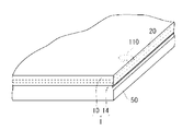
- the thickness of the weir-like portion 20 is larger than the thickness of the layer-like portion 18, as shown in FIG. 13, when the display panel 50 and the laminate 1 are bonded together, Even if the gap 110 remains at the interface between the adhesive layer 14 and the adhesive layer 14, the gap 110 is blocked by the weir-like portion 20, so that the gap 110 does not open to the outside and becomes an independent gap 110.
- the difference between the thickness of the dam-like portion 20 and the thickness of the layer-like portion 18 is preferably 0.05 mm or less, and more preferably 0.03 mm or less, from the viewpoint of suppressing generation of a gap due to a step between the dam-like portion 20 and the layer-like portion 18. .
- the difference between the thickness of the weir 20 and the thickness of the layer 18 is obtained by measuring the total thickness of the transparent surface 10 and the layer 18 or the weir 20 formed thereon using a laser displacement meter. Find from the difference.
- the thickness of the layered portion 18 is the thickness of the peripheral portion of the layered portion 18 in contact with the weir-shaped portion 20.
- the storage shear elastic modulus at 35 ° C. of the weir 20 may be a lower limit of the shear elastic modulus at which the weir 20 can be self-supported, and the upper limit may be 15 times the storage shear elastic modulus of the layer 18 at 35 ° C. More specifically, it is preferably 1 to 150 kPa. By setting the storage shear elastic modulus at 35 ° C. of the weir 20 to 1 kPa or more, the weir 20 can be made independent.
- the storage shear elastic modulus at 35 ° C. of the weir 20 is larger than the storage shear elastic modulus at 35 ° C. of the layered portion 18. If the storage shear elastic modulus of the weir-like part 20 is larger than the storage shear elastic modulus of the layered part 18, when the display panel and the transparent surface material 1 with the adhesive layer are bonded together, Even if voids remain at the interface between the display panel and the adhesive layer 14, the voids are not easily opened to the outside and are likely to become independent voids.
- the transparent surface material 1 with an adhesion layer and a to-be-bonded body are bonded by making the storage shear elastic modulus in 35 degreeC of the weir-like part 20 into 15 times or less of the storage shear elastic modulus in 35 degreeC of the layered part 18.
- the display nonuniformity by the difference in the storage shear elastic modulus of the dam-like part 20 and the layered part 18 can be suppressed.
- the storage shear elastic modulus at 35 ° C. of the weir-shaped portion made of a cured product of the photocurable resin composition is a value measured by the following method.
- the storage shear modulus at 35 ° C. of the layered portion is a value measured in the same manner.
- the storage shear modulus at 35 ° C. of the weir 20 after curing was measured using a rheometer (manufactured by Anton titanium, modular rheometer Physica MCR-301) and a measuring spindle and a transparent plate.
- an uncured second resin composition is disposed in the gap, and curing is performed while irradiating the uncured second resin composition with light necessary for curing.
- the storage shear modulus of the process was measured, and the measured value under the curing conditions when forming the weir 20 was defined as the storage shear modulus of the weir 20.
- the protective film 16 is required not to be firmly adhered to the adhesive layer 14 and to be able to be attached to a support surface material in the manufacturing method of the present invention described later. Therefore, the protective film 16 is preferably a self-adhesive protective film in which one side of a base film having relatively low adhesion, such as polyethylene, polypropylene, and fluorine resin, is an adhesive surface.
- the adhesive strength of the adhesive surface of the protective film 16 is preferably 0.01 to 0.1 N, preferably 0.02 to 0.06 N in a 50 mm wide specimen in a 180 degree peel test with a peel rate of 300 mm / min. Is more preferable. If the said adhesive force is more than a lower limit, sticking to a support surface material is possible. If the said adhesive force is below an upper limit, it is easy to peel the protective film 16 from a support surface material.
- the thickness of the protective film 16 varies depending on the resin to be used, but when a relatively flexible film such as polyethylene or polypropylene is used, it is preferably 0.04 to 0.2 mm, more preferably 0.06 to 0.1 mm. . If the thickness of the protective film 16 is equal to or greater than the lower limit value, deformation of the protective film 16 can be suppressed when the protective film 16 is peeled from the adhesive layer 14. If the thickness of the protective film 16 is not more than the upper limit value, the protective film 16 is easily bent at the time of peeling, and the protective film 16 is easily peeled off from the adhesive layer 14.
- a back layer on the back surface opposite to the adhesive surface of the protective film 16
- peeling from the adhesive layer 14 can be further facilitated.
- a film with relatively low adhesion such as polyethylene, polypropylene, and fluorine resin.
- a release agent such as silicone may be applied to the protective film 16 within a range that does not adversely affect the adhesive layer 14.
- a barrier layer that prevents gas (oxygen gas, nitrogen gas, water vapor, etc.) from passing through the protective film 16 and entering the adhesive layer 14 from a part of the protective film.
- the content W1 (% by mass) of the non-curable oligomer (II) contained in the layered portion and the content W2 of the non-curable oligomer (II ′) contained in the weir-shaped portion Since the difference (W1-W2) with respect to (mass%) is 40 or less, defects will occur in the layered portion and the weir-shaped portion even after a predetermined time has elapsed after bonding with the surface material to be bonded. Difficult to improve product reliability.
- the transparent surface material 1 with the adhesion layer of the example of illustration is an example whose transparent surface material is a protective plate of a display apparatus
- the transparent surface material with an adhesion layer of this invention is not limited to the thing of an example of illustration. Any transparent surface material with an adhesive layer in which a specific adhesive layer is formed on at least one surface of the transparent surface material may be used.
- the transparent surface material with an adhesive layer of the present invention may be a transparent surface material with an adhesive layer in which a specific adhesive layer is formed on both surfaces of the transparent surface material.
- polarizing means film-like absorption polarizer, wire grid polarizer, etc.
- Light modulation means a retardation film such as a quarter-wave plate, a retardation film patterned in a stripe shape, or the like
- the method for producing a transparent surface material with an adhesive layer of the present invention having a protective film is a method having the following steps (a) to (e).
- the first composition is contained between the transparent surface material in a reduced pressure atmosphere and the protective film adhered to the support surface material, under a high pressure atmosphere such as an atmospheric pressure atmosphere, In this method, the encapsulated first composition is cured to form a layered portion.
- the method of containing the first composition under reduced pressure is not a method of injecting the first composition into a narrow and wide space between the transparent surface material and the protective film adhered to the support surface material, but a transparent surface material.
- the first composition is supplied to almost the entire surface of the first composition, and the first composition is then placed between the transparent surface material and the protective film adhered to the supporting surface material by stacking the protective film adhered to the supporting surface material.
- Adopt a method to contain
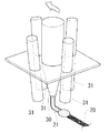
- a photocurable liquid second composition is applied by a dispenser 30 or the like along the light-shielding printing portion 12 at the peripheral edge of the transparent face material 10, and the uncured weir-like portion 20 ⁇ / b> A.
- coating of a 2nd composition is performed using a printing machine, a dispenser, etc.
- step (a) for example, as shown in FIGS.
- the uncured weir 20A may be in an uncured state where no curing reaction is performed, or may be in a partially cured state that is partially cured. Partial curing in the uncured weir 20A is performed by light irradiation when the second composition is a photocurable resin composition.
- the photocurable resin composition is partially cured by irradiating ultraviolet light or short wavelength visible light from a light source (ultraviolet lamp, high pressure mercury lamp, UV-LED, etc.).
- a plurality of UV-LED light sources 31 are disposed so as to surround the dispenser 30, so that a transparent surface material (protection plate)
- the second resin composition 21 applied on the substrate 10 can be uniformly exposed and cured immediately after application.
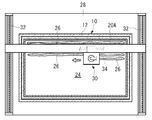
- a liquid first composition 26 is supplied to a rectangular region 24 surrounded by the uncured weir-like portion 20 ⁇ / b> A on the transparent face material 10.
- the supply of the first composition 26 is performed by placing the transparent surface material 10 flat on the lower platen 28 and moving the first composition 26 into a linear or belt shape by a dispenser 30 that moves in the horizontal direction. Or it implements by supplying in a dot form.
- the dispenser 30 of this example is horizontally movable over the entire range of the region 24 by a known horizontal movement mechanism including a pair of feed screws 32 and a feed screw 34 orthogonal to the feed screw 32.
- the supply amount of the first composition 26 is such that the space formed by the uncured weir 20A, the transparent face material 10 and the protective film 16 is filled with the first composition 26, so that the transparent face material 10 and the protective film 16 are filled. Is set in advance to a predetermined interval (that is, the layered portion 18 has a predetermined thickness). At this time, it is preferable to consider in advance volume reduction due to curing shrinkage of the first composition 26. Therefore, the supply amount of the first composition 26 is preferably such that the thickness of the layered portion 18 before curing is slightly larger than the predetermined thickness of the layered portion 18 after curing.
- the peripheral portion of the first composition 26 spreads outward, and the peripheral portion is prevented from being thinned, and the entire thickness of the first composition 26 is made uniform. Can keep. By making the entire thickness of the layered portion 18 uniform, it is preferable to easily prevent a void from remaining at the interface in bonding with the object to be bonded.
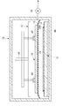
- the transparent surface material 10 and the support surface material 36 to which the protective film 16 is attached are carried into the decompression device 38.
- the protective film 16 is attached to the support surface material 36 by bonding the protective film 16 supplied as a roll-shaped roll to the support surface material 36 using a rubber roll or the like. At this time, a rubber roll can be pressed against the support surface material 36 or bonded in a reduced pressure space so that no gap is generated between the support surface material 36 and the adhesive surface of the protective film 16. It is preferable to use the protective film 16 that is slightly larger than the support surface material 36 so that the end of the protective film 16 can be easily gripped when peeled from the adhesive layer 14.
- An upper surface plate 42 having a plurality of suction pads 40 is disposed in the upper portion of the decompression device 38, and a lower surface plate 44 is disposed in the lower portion.
- the upper surface plate 42 can be moved in the vertical direction by an air cylinder 46.
- the support surface material 36 is attached to the suction pad 40 with the surface to which the protective film 16 is attached facing down.
- the transparent face material 10 is fixed on the lower surface plate 44 with the surface to which the first composition 26 is supplied facing up. In this way, the first composition 26 on the transparent face material 10 and the protective film 16 on the surface of the support face material 36 are opposed to each other without being in contact with each other.
- the support surface material 36 is a transparent surface material such as a glass plate or a resin plate.
- the thickness of the glass plate used as the support surface material 36 is preferably 0.5 to 10 mm, particularly preferably 1.0 to 5.0 mm. If the thickness of the glass plate is equal to or greater than the lower limit, the support surface material 36 is unlikely to warp or bend. If the thickness of the glass plate is equal to or less than the upper limit value, the mass of the support surface material 36 is not unnecessarily increased, and the support surface material 36 is not easily displaced when the precursor laminate before curing of the adhesive layer 14 is moved.
- the reduced-pressure atmosphere is preferably 1 kPa or less, more preferably 10 to 100 Pa, and further preferably 15 to 40 Pa.
- each component curable compound, photopolymerization initiator, polymerization inhibitor, chain transfer agent, light stabilizer, etc. contained in the first composition is difficult to vaporize.
- the time required to achieve the reduced pressure atmosphere is shortened.
- the transparent surface material 10 waiting below is held in a state where the support surface material 36 is adsorbed and held by the adsorption pad 40 of the upper surface plate 42. Then, the air cylinder 46 is moved downward. Then, the transparent surface material 10 and the support surface material 36 to which the protective film 16 is adhered are overlapped via the uncured weir-shaped portion 20A, and the transparent surface material 10, the protective film 16, and the uncured weir.
- the precursor layered body in which the uncured layered part made of the first composition 26 is sealed by the shaped part 20A is configured, and the precursor layered body is held for a predetermined time in a reduced pressure atmosphere. In the precursor laminate, the first composition 26 is expanded by the weight of the support surface material 36, the pressure from the moving support mechanism, and the like, and the space is filled with the first composition 26. Is formed.
- the time from when the transparent face material 10 and the support face material 36 are overlapped to the time when the reduced pressure atmosphere is released is not particularly limited, and the reduced pressure atmosphere may be released immediately after sealing the first composition 26, After sealing the first composition 26, the reduced pressure state may be maintained for a predetermined time.
- the first composition flows in the sealed space, the distance between the transparent surface material 10 and the protective film 16 attached to the support surface material 36 becomes uniform, and the atmospheric pressure Even if it raises, it becomes easy to maintain a sealed state.
- the time for maintaining the reduced pressure state may be several hours or longer, but is preferably within 1 hour, more preferably within 10 minutes from the viewpoint of production efficiency.
- the thickness can be relatively thick, 0.03 to 2 mm.
- step (c) the reduced pressure atmosphere is released, and the precursor laminate is placed in a higher pressure atmosphere than in step (c).
- the precursor laminate is taken out from the decompression device 38.
- the transparent face material 10 and the support face material 36 are pressed in a direction in close contact with the increased pressure. For this reason, even if a void exists in the sealed space in the precursor laminate, the uncured layered portion flows in the void, and the entire sealed space is uniformly filled with the uncured layered portion.
- the pressure atmosphere in step (d) may be an atmospheric pressure atmosphere or a higher pressure.
- the pressure atmosphere in the step (d) is preferably 80 to 120 kPa.
- the pressure atmosphere in the step (d) is most preferably an atmospheric pressure atmosphere because operations such as curing of the layered portion 18 can be performed without requiring special equipment.
- the time from when the precursor laminate is placed in a higher pressure atmosphere than in step (c) to the start of curing of the uncured layered portion is not particularly limited. .
- the time required for the process becomes the high pressure holding time. Therefore, if there is no void in the sealed space of the precursor laminate already when placed in an atmospheric pressure atmosphere, or if the void disappears during the process, the uncured layered part is immediately cured. Can do.
- the precursor laminate is held in an atmosphere at a higher pressure than in step (c) until the voids disappear.
- the high-pressure holding time may be a long time of one day or longer, but is preferably within 6 hours from the viewpoint of production efficiency, more preferably within 1 hour, and particularly within 10 minutes from the viewpoint of further increasing production efficiency. preferable.
- the uncured weir-like portion 20A and the layered portion inside the precursor laminate are cured to form the adhesive layer 14 having the layered portion 18 and the layered portion 20.
- the uncured weir 20A may be cured at the same time as the uncured layer is cured, or the uncured weir 20A may be cured before the uncured layer is cured.
- the uncured layered portion and the uncured weir-shaped portion 20A are made of a photocurable resin composition, light (from the support surface material 36 side to the uncured weir-shaped portion 20A and the uncured layered portion is light ( UV light and short wavelength visible light) to cure.
- the layered portion 18 and the weir-shaped portion 20 are cured by irradiating ultraviolet light or short wavelength visible light from a light source (ultraviolet lamp, high pressure mercury lamp, UV-LED, etc.).
- a light source ultraviolet light or visible light of 450 nm or less is preferable.
- the light shielding printing part is formed in the peripheral part of the transparent surface material, or when the antireflection layer is provided in the transparent surface material, light is irradiated from the support surface material side.
- the layered portion 18 When the layered portion 18 is made of a photocurable first composition and when a suitable shear elastic modulus cannot be obtained by sufficient photocuring, light irradiation is interrupted during curing, and the surface material to be bonded ( After bonding with a display panel or the like), the layered portion 18 may be irradiated with light again or heated to accelerate the curing of the layered portion 18. When curing is accelerated by heating, a small amount of a thermal polymerization initiator may be included in the photocurable first composition. Moreover, even if it is a case where a thermal polymerization initiator is not used together, the hardening state of the layer part 18 can be stabilized by heat-holding after incomplete photocuring, and it is preferable. If the first composition and the second composition are photocurable, the transparent surface material 1 with an adhesive layer can be produced at a low temperature that the film can withstand, which is advantageous in terms of protecting the protective film.
- the support surface material 36 is peeled from the protective film 16. Thereby, the transparent surface material 1 with the adhesion layer with the protective film 16 is obtained.
- the adhesive layer may be cooled. By cooling the pressure-sensitive adhesive layer, deformation of the pressure-sensitive adhesive layer when peeling the protective film can be suppressed, increasing the uniformity of the thickness of the pressure-sensitive adhesive layer after peeling the protective film, and bonding with the display panel The generation of voids can also be suppressed.
- the temperature at which the adhesive layer is cooled varies depending on the glass transition temperature of the resin used as the adhesive layer. It is preferable to set the temperature or lower.
- the lower limit temperature is not particularly defined, but is preferably ⁇ 30 ° C. or higher because some resins used for the protective film may become brittle at low temperatures and tear the film during peeling.
- the cooling time is preferably 5 minutes, but can be adjusted depending on the ease of peeling.
- the transparent surface material 1 with an adhesive layer of the present embodiment can be produced without any problem by the same production method as that of the first embodiment.
- the layered portion 18 and the weir-shaped portion 21 constituting the pressure-sensitive adhesive layer 14 may include the non-curing component, and both may be included.
- the difference between the non-curing component (W1) contained in the layered portion 18 and the non-curing component (W2) contained in the weir-like portion 21 is 40 or less.
- the laminate of the present invention is a laminate in which the transparent surface material with an adhesive layer of the present invention (one having no protective film) and the surface material to be bonded are bonded.
- the transparent surface material with an adhesive layer and a to-be-bonded surface material are bonded so that the adhesive layer of a transparent surface material with an adhesive layer may contact with a to-be-bonded surface material.
- the photocurable resin composition can be cured from the transparent face material side.
- the surface material to be bonded may be transparent or opaque.
- a display device is preferred as the laminate of the present invention.
- FIG. 12 is a cross-sectional view illustrating an example of a display device.
- the display device 2 includes a display panel 50 that is a surface material to be bonded, and a transparent surface material 1 with an adhesive layer that is bonded to the display panel 50 so that the adhesive layer 14 is in contact with the display panel 50 (does not have a protective film). And a flexible printed wiring board 60 (FPC) on which a driving IC for operating the display panel 50 connected to the display panel 50 is mounted.
- the display device 2 includes the transparent surface material 10, the display panel 50, and the adhesive layer 14 sandwiched between the transparent surface material 10 and the display panel 50.
- the surface material 50 to be bonded in the illustrated example is a display panel, and a transparent substrate 52 provided with a color filter and a transparent substrate 54 provided with a TFT (thin film transistor) are bonded via a liquid crystal layer 56, and a pair thereof is bonded.
- a liquid crystal panel having a configuration sandwiched between polarizing plates 58.
- the surface material to be bonded is a display panel, but the surface material to be bonded is not limited to the display panel, and may be a touch panel, for example.
- a display device manufacturing method will be described as an example of the laminate manufacturing method of the present invention.
- a display panel and a transparent surface with an adhesive layer are stacked in a reduced pressure atmosphere of 10 kPa or less so that the adhesive layer is in contact with the display panel. It is a method of pasting.
- the surface of the adhesive layer is covered with a protective film as in the transparent surface material 1 with the adhesive layer shown in FIG. 1, after the protective film is peeled off, the display panel and the transparent surface material with the adhesive layer are bonded.
- the pressure-reduced atmosphere when the display panel and the transparent surface material with the adhesive layer are bonded is 10 kPa or less, preferably 1 to 100 Pa, and more preferably 5 to 50 Pa.
- a step of obtaining a precursor laminate in which is sealed (I) In a state where the precursor laminate is placed under a higher pressure atmosphere than in the step (h), the uncured layer portion and the uncured weir portion are cured, and the layer portion 18 and the weir portion 20 are The process of forming the adhesion layer 14 which has.
- Step (f) The step (f) can be performed in the same manner as in the step (a) except that the display panel 50 is used instead of the transparent surface material 10 (protective plate) in the step (a).
- Step (g) The step (g) can be performed in the same manner as the step (b).
- Step (h) The step (h) can be performed in the same manner as the step (c) except that the transparent face material 10 (protective plate) is used instead of the support face material 36 to which the protective film 16 is bonded in the step (c).
- Step (i) can be performed in the same manner as in step (d).
- the flexible printed wiring board 60 (FPC) may be connected before the step (a) or after the step (a).
- a transparent plate made of soda lime glass having a length of 100 mm, a width of 100 mm, and a thickness of 3 mm On one side of a transparent plate made of soda lime glass having a length of 100 mm, a width of 100 mm, and a thickness of 3 mm, a protective film of 130 mm in length, 130 mm in width, and 0.75 mm in thickness (manufactured by Tosero, Puretect VLH-9) A support surface material-ii having a protective film attached thereto was prepared by attaching using a rubber roll so that the adhesive surface of the protective film was in contact with the glass.
- a polarizing plate with an adhesive layer (Polatechno Co., Ltd., KN-18240T) is attached to one surface of soda lime glass having a length of 100 mm, a width of 100 mm, and a thickness of 1.7 mm.
- a to-be-bonded surface material-iii that substitutes the display panel was used.
- the number of curable functional groups of the oligomer (A-1) was 2, the number average molecular weight was about 24,000, and the viscosity at 25 ° C. was about 830 Pa ⁇ s.
- 40 parts by mass of oligomer (A-1), 30 parts by mass of 2-hydroxybutyl methacrylate (manufactured by Kyoeisha Chemical Co., Ltd., light ester HOB), and 30 parts by mass of n-dodecyl methacrylate were mixed uniformly, To 100 parts by mass of the mixture, 0.3 part by mass of bis (2,4,6-trimethylbenzoyl) -phenylphosphine oxide (photopolymerization initiator, manufactured by Ciba Specialty Chemicals, IRGACURE 819), and 2, 0.04 part by mass of 5-di-tert-butylhydroquinone (polymerization inhibitor, manufactured by Tokyo Chemical Industry Co., Ltd.), 0.3 part by mass of UV absorber (manufactured by Ci
- a base composition -iv. 40 parts by mass of the oligomer (A-1), 40 parts by mass of 2-hydroxybutyl methacrylate (manufactured by Kyoeisha Chemical Co., Ltd., light ester HOB) and 20 parts by mass of n-dodecyl methacrylate were mixed uniformly.
- the base composition-iv or the base composition-v and the non-curable oligomer (II-i) are uniformly dissolved in the proportions shown in Table 1, and the decompression device is opened in the container.
- the defoaming treatment was performed by depressurizing the interior of the decompression device to about 20 Pa and holding it for 10 minutes to obtain a first composition-1 and a first composition-2.
- the non-curable oligomer (II-i) the same bifunctional polypropylene glycol having a molecular terminal modified with ethylene oxide (number average molecular weight calculated from the hydroxyl value: the same as that used in the synthesis of the oligomer (A-1) 4000) was used.
- the prepolymer 2-hydroxyethyl acrylate was added at a molar ratio of 1: 2, reacted at 70 ° C., and diluted with 30% by mass of isobornyl acrylate, urethane acrylate oligomer (A′-2) (hereinafter referred to as “the prepolymer”) And “Oligomer (A′-2)”).
- the number of curable functional groups of the oligomer (A′-2) was 2, the number average molecular weight was 55000, and the viscosity at 60 ° C. was 580 Pa ⁇ s.
- the base composition-vi or the base composition-vii is placed in a container in an open state while being placed in a container, and the pressure reduction apparatus is depressurized to about 20 Pa and held for 10 minutes to perform defoaming treatment.
- a second composition-1 was obtained.
- the base composition-v or the base composition-vii and the non-curable oligomer (II′-i) are uniformly dissolved in the proportions shown in Table 1, and are kept open in the decompression apparatus while being put in the container.
- the defoaming treatment was performed by reducing the pressure in the decompression device to about 20 Pa and holding for 10 minutes to obtain second composition-2 to second composition-7.
- the non-curable oligomer (II′-i) the same non-curable oligomer (II-i) was used.
- Example 1 (Process (a)) The second composition-1 was applied with a dispenser over the entire circumference at a position of about 7 mm from the inner edge of the light-shielding printing portion of the transparent face material-i so that the width was about 1 mm and the coating thickness was about 0.6 mm. A curing weir was formed. Next, UV light from a chemical lamp (manufactured by NEC, FL15BL, peak wavelength: 365 nm, irradiation intensity: 2 mW / cm 2 ) and visible light of 450 nm or less were formed on the transparent surface material-i for 30 seconds. The weir-shaped portion was irradiated uniformly. This thickened the uncured weir.
- a chemical lamp manufactured by NEC, FL15BL, peak wavelength: 365 nm, irradiation intensity: 2 mW / cm 2
- the first composition-1 was supplied to a plurality of locations in a region inside the uncured weir-like portion formed on the transparent face material-i using a dispenser so that the total mass became 2.5 g. During the supply of the first composition-1, there was no breakage such as breakage, and the shape of the uncured weir was maintained.
- the upper and lower surface plates are brought close to each other by the lifting device in the decompression device, and the transparent surface material-i and the support surface material-ii to which the protective film is adhered are pressured at 2 kPa through the first composition-1. And pressed for 10 seconds. Static electricity is removed from the electrostatic chuck, the supporting surface material ii is separated from the upper surface plate, and the pressure reducing device is returned to the atmospheric pressure atmosphere in about 15 seconds. With the transparent surface material i, the protective film, and the uncured weir A precursor laminate-1 in which the uncured layered portion of the first composition-1 was sealed was obtained. In the precursor laminate-1, the shape of the uncured weir-like portion was maintained in an almost initial state.
- Examples 2 to 6, Comparative Example 1 Transparent surface material with adhesive layer-2 to transparent surface material with adhesive layer-7 were obtained in the same manner as in Example 1 except that the types of the first composition and the second composition were changed as shown in Table 2. .
- Step evaluation (1) Acceleration test The protective film was peeled off from the transparent surface material with an adhesive layer obtained in each example, and stored in a thermostatic bath at 80 ° C for 5 days.
- (2) Shape Evaluation of Adhesive Layer For the shape evaluation of the adhesive layer, a digital microscope VHX-1000 manufactured by Keyence Corporation was used, and the shape was measured using the depth of focus. The measurement location was a part extending over a distance of about 5 mm on the adhesive layer surface extending from the outer peripheral edge of the weir-like portion at the center of one side of the adhesive layer on the transparent surface material-i to the layered portion. In the measurement, a silver paste was thinly applied to the surface of the adhesive layer for the purpose of improving measurement sensitivity.
- the measurement was performed before and after the acceleration test (1).
- the step between the weir-like part and the layer-like part before and after the acceleration test was evaluated.
- the difference in height between the highest point and the lowest point in the measurement location was calculated as a step.
- the transparent surface material with an adhesive layer from which the protective film has been peeled off is placed on the lower surface plate in the decompression device in which a pair of surface plate lifting devices are installed. It was placed flat so that the surface of the adhesive layer was on top.
- the surface material to be bonded-iii was held on the lower surface of the upper surface plate of the lifting device in the decompression device using an electrostatic chuck so that the distance from the transparent surface material with adhesive layer-1 was 10 mm.
- the decompression device was sealed and evacuated until the pressure in the decompression device reached about 30 Pa.
- the upper and lower surface plates are brought close to each other by an elevating device in the decompression device, and the surface material to be bonded -iii and the transparent surface material with adhesive layer-1 are pressure-bonded through the adhesive layer at a pressure of 2 kPa and held for 10 seconds. It was. Static electricity is removed from the electrostatic chuck, the surface material to be bonded -iii is separated from the upper platen, and the pressure reducing device is returned to atmospheric pressure in about 20 seconds, and adhesion is made between the transparent surface material -i and the surface material to be bonded -iii. A layered product-1 in which the layers were sandwiched was obtained.
- Laminate-1 When the laminate-1 was observed immediately after lamination, many fine voids (bubbles) were observed at the interface between the surface material to be bonded-iii and the adhesive layer of the transparent surface material with adhesive layer-1. Laminate-1 was allowed to stand, and the time until voids disappeared (void disappearance time) was measured. Laminates-2 to -7 were obtained in the same manner using the transparent face materials with adhesive layer-2 to -7, and the void disappearance time was measured. The results are shown in Table 1. The void disappearance time was the average of the results of two samples.
- Example 7 [Transparent surface material] Soda lime glass having a length of 250 mm, a width of 190 mm, and a thickness of 1.3 mm was used as a transparent surface material. In this example, in order to make it easy to confirm the influence of display unevenness, a glass substrate on which no light-shielding print portion is formed is used as a transparent surface material.
- a transparent plate made of soda lime glass having a length of 100 mm, a width of 100 mm, and a thickness of 3 mm On one side of a transparent plate made of soda lime glass having a length of 100 mm, a width of 100 mm, and a thickness of 3 mm, a protective film of 130 mm in length, 130 mm in width, and 0.75 mm in thickness (manufactured by Tosero, Puretect VLH-9) A support surface material to which the protective film was attached was prepared by sticking using a rubber roll so that the adhesive surface of the protective film was in contact with the glass.
- the base composition vi was used as the third resin composition.
- the storage shear modulus of the resin layer obtained by curing the first to third resin compositions is determined using a rheometer (Physica MCR301, manufactured by Anton Paar).
- the resin composition was sandwiched between a soda lime glass stage and a measuring spindle (D-PP20 / AL / S07, manufactured by Anton Paar), and a black light (35 ° C. under a nitrogen atmosphere)
- a photo-curable resin composition for resin layer formation was cured by applying a 1% dynamic shear strain while irradiating with light of 2 mW / cm 2 for 10 minutes by FL15BL (manufactured by NEC Corporation).
- the storage shear modulus of the resin layer obtained from each resin composition is shown in Table 3 below.
- a second resin composition is applied with a dispenser over the entire circumference at a position of about 25 mm from the outer peripheral edge of the transparent surface material so as to have a width of about 1 mm and a coating thickness of about 0.6 mm, and an LED light source associated with the dispenser. Then, UV light was irradiated to form a partially cured weir-shaped portion (see FIGS. 4 to 5).
- the first resin composition was supplied to a plurality of locations in a region inside the weir-shaped portion using a dispenser so that the total mass was 2.5 g. During the supply of the first resin composition, there was no breakage such as breakage, and the shape of the uncured weir was maintained.
- the surface coated with the first resin composition is placed on the lower surface plate in the decompression device (see FIG. 6) in which the lifting device for the pair of surface plates is installed. And evacuated until the pressure in the decompression device reached about 40 Pa.
- the upper and lower surface plates are brought close to each other by an elevating device in the depressurization apparatus, and the transparent surface material and the support surface material to which the protective film is attached are pressure-bonded through the first resin composition at a pressure of 2 kPa. And held for 10 seconds for bonding.
- the inside of the decompression device was returned to the atmospheric pressure atmosphere to obtain a precursor laminate in which the first resin composition was sealed with a transparent surface material, a protective film, and a weir-shaped portion.
- the precursor laminate is uniformly irradiated with UV light from a chemical lamp (NEC Corporation, FL15BL, peak wavelength: 365 nm, irradiation intensity: 2 mW / cm 2 ) and visible light of 450 nm or less from the support surface material side for 10 minutes.
- a chemical lamp NEC Corporation, FL15BL, peak wavelength: 365 nm, irradiation intensity: 2 mW / cm 2
- visible light 450 nm or less from the support surface material side for 10 minutes.
- the adhesion layer was formed by hardening a weir-like part (2nd resin composition) and a 1st resin composition. Irradiation intensity was measured using an illuminometer (manufactured by USHIO INC., UV intensity meter unimeter UIT-101). The thickness of the layered portion after curing was approximately uniform at 0.4 mm.
- the support surface material was peeled off from the protective film to produce a transparent surface material with an adhesive layer on which the protective film was stuck.
- Example 7 in which the ratio of the elastic modulus between the layered portion and the weir-shaped portion was the lowest, display unevenness was not visible. It was confirmed that good visibility could be maintained by keeping the ratio of elastic modulus between the layered portion and the weir-shaped portion low.
Abstract
透明面材(10)と、透明面材(10)の表面に形成された、層状部(18)および堰状部(20)を有する粘着層(14)とを有し、層状部(18)中の非硬化性オリゴマー(II)の質量%で表される含有量W1と、堰状部(20)中の非硬化性オリゴマー(II')の質量%で表される含有量W2との差(W2-W1)を40以下とすることを特徴とする、粘着層付き透明面材1;並びに、表示パネルと、粘着層が表示パネルに接するように、表示パネルに貼合された粘着層付き透明面材(1)と、を有する表示装置。
Description
本発明は、粘着層付き透明面材、積層体、表示装置、およびそれらの製造方法に関する。
たとえば、保護板(透明面材)により表示パネル(被貼合面材)が保護された表示装置として、表示パネルと保護板とが粘着層を介して貼合された表示装置が知られている。該表示装置のような一対の面材間に粘着層が挟まれた積層体に用いられる粘着層としては、面材の表面に沿って広がる層状部と、前記層状部の周縁を囲む堰状部とを有し、前記層状部が、硬化性化合物と非硬化性オリゴマーとを含む硬化性樹脂組成物の硬化物からなる粘着層が提案されている(特許文献1、2参照)。
前記表示装置のような積層体の製造方法としては、たとえば、下記の方法(i)および(ii)がある。
(i)透明面材表面の周縁部に形成した未硬化の堰状部に囲まれた領域内に層状部を形成する硬化性樹脂組成物を供給した後、減圧雰囲気下にて保護フィルムが貼着された支持面材を重ね、大気圧雰囲気下に戻して未硬化の堰状部と層状部を硬化させて、透明面材上に粘着層が形成され、該粘着層が保護フィルムで覆われた積層体を得る。その後、所望の時点で該積層体の保護フィルムを剥離し、減圧雰囲気下にて該積層体と被貼合面材とを粘着層が被貼合面材に接するように重ねて貼合し、これを大気圧雰囲気下に戻す。
(ii)被貼合面材表面の周縁部に形成した未硬化の堰状部に囲まれた領域に層状部を形成する樹脂組成物を供給した後、減圧雰囲気下にて透明面材を重ね、大気圧雰囲気下に戻して未硬化の堰状部と層状部を硬化させる。
方法(i)では、透明面材上に粘着層が形成された粘着層付き透明面材と被貼合面材とを減圧雰囲気下で貼合した際には、表示パネルと粘着層との界面に空隙が生じる。しかし、貼合したものを大気圧雰囲気下に戻した際に、該空隙内の圧力(減圧のまま)と粘着層にかかる圧力(大気圧)との差圧によって、該空隙の体積が減少し、空隙は消失する。方法(ii)でも同様に、減圧雰囲気下で透明面材を重ねた際に空隙が生じても、該空隙は大気圧雰囲気下に戻した際に消失する。
層状部を形成する硬化性樹脂組成物に、硬化反応に関与しない非硬化性オリゴマーが含まれていると、非硬化性オリゴマーが含まれていない場合に比べて形成される層状部の流動性が高い。そのため、層状部が空隙へと流動しやすく、粘着層と面材との界面に生じた空隙は短時間で消失する。
また、非硬化性オリゴマーが含まれていることで層状部は低弾性となる。そのため、前記粘着層と接する表示パネルにかかる応力は小さく、表示装置の表示ムラが抑制される。
また、非硬化性オリゴマーが含まれていることで層状部は低弾性となる。そのため、前記粘着層と接する表示パネルにかかる応力は小さく、表示装置の表示ムラが抑制される。
しかし、上記粘着層付き透明面材では、所定の時間経過後、粘着層の層状部から堰状部に非硬化性オリゴマーが拡散し、堰状部と層状部との界面付近で非硬化性オリゴマーが拡散した影響により堰状部と層状部の厚みに差が生じるため、貼合した時に、被貼合面との間に空隙が発生したり貼合不良が生じる可能性がある。また、粘着層付き面材と被貼合面材と貼合した積層体を所定時間経過させると、非硬化性オリゴマーが堰状部に拡散して堰状部の体積が増加することにより、接合不良や被貼合面の空隙が生じる恐れがある。
本発明は、所定の時間経過後であっても層状部および堰状部に不良が発生しにくい粘着層付き透明面材、表示装置、および積層体を提供する。また、本発明は、所定の時間経過後であっても層状部および堰状部に不良が発生しにくい粘着層付き透明面材および表示装置の製造方法を提供する。
本発明の粘着層付き透明面材は、透明面材と、前記透明面材の少なくとも一方の表面に形成された粘着層と、を有し、前記粘着層が、前記透明面材の表面に沿って広がる層状部と、前記層状部の周縁を囲む堰状部と、を有し、前記堰状部が、下記硬化性化合物(I’)および下記非硬化性オリゴマー(II’)を含む堰状部形成用硬化性樹脂組成物の硬化物からなり、前記層状部が、下記硬化性化合物(I)および下記非硬化性オリゴマー(II)を含む層状部形成用硬化性樹脂組成物の硬化物からなり、前記層状部中の前記非硬化性オリゴマー(II)の質量%で表される含有量W1と前記堰状部中の前記非硬化性オリゴマー(II’)の質量%で表される含有量W2との差(W1-W2)が40以下であることを特徴とする。
硬化性化合物(I’):ウレタンアクリレートオリゴマー(A’)と、硬化性官能基を1個以上有する分子量600未満のモノマー(B’)とを含む。
非硬化性オリゴマー(II’):前記層状部形成用硬化性樹脂組成物および堰状部形成用硬化性樹脂組成物のいずれの硬化時にも前記硬化性化合物(I’)と硬化反応しない、水酸基を有するオリゴマー。
硬化性化合物(I):ウレタンアクリレートオリゴマー(A)と、硬化性官能基を1個以上有する分子量600未満のモノマー(B)とを含む。
非硬化性オリゴマー(II):前記層状部形成用硬化性樹脂組成物および堰状部形成用硬化性樹脂組成物のいずれの硬化時にも前記硬化性化合物(I)と硬化反応しない、水酸基を有するオリゴマー。
前記ウレタンアクリレートオリゴマー(A)および(A’)は、ポリオキシアルキレンポリオールおよびポリイソシアネートを原料として合成されたウレタンアクリレートオリゴマーであることが好ましい。
前記非硬化性オリゴマー(II)および(II’)は、ポリオキシアルキレンポリオールであることが好ましい。
前記非硬化性オリゴマー(II)および(II’)の水酸基1個当たりの数平均分子量は、400~8000であることが好ましい。
前記ウレタンアクリレートオリゴマー(A)の数平均分子量は、1000~100000であることが好ましい。
前記層状部形成用硬化性樹脂組成物が光重合開始剤(C1)を含み、前記堰状部形成用硬化性樹脂組成物が光重合開始剤(C2)を含むことが好ましい。
前記非硬化性オリゴマー(II)および(II’)は、ポリオキシアルキレンポリオールであることが好ましい。
前記非硬化性オリゴマー(II)および(II’)の水酸基1個当たりの数平均分子量は、400~8000であることが好ましい。
前記ウレタンアクリレートオリゴマー(A)の数平均分子量は、1000~100000であることが好ましい。
前記層状部形成用硬化性樹脂組成物が光重合開始剤(C1)を含み、前記堰状部形成用硬化性樹脂組成物が光重合開始剤(C2)を含むことが好ましい。
本発明の粘着層付き透明面材では、前記堰状部の35℃における貯蔵せん断弾性率は、前記層状部の35℃における貯蔵せん断弾性率以上かつ15倍以下であることが好ましい。
前記堰状部は、35℃における貯蔵せん断弾性率が、1~150kPaであることが好ましい。
前記層状部は、35℃における貯蔵せん断弾性率が、1~100kPaであることが好ましい。
本発明の粘着層付き透明面材における前記透明面材は、その表面の周縁部に形成された遮光印刷部を備え、少なくとも、層状部および堰状部の一部が、前記透明面材の表面の面内方向において、前記遮光印刷部よりも内側に位置することが好ましい。
さらに、前記堰状部は、数平均分子量30000~100000のオリゴマーからなる硬化物を含むことが好ましい。前記堰状部は、分子量125~600の、酸基を含まないモノマーからなる硬化物を含むことが好ましい。前記堰状部は、未硬化時における粘度が40Pa・s~100Pa・sであることが好ましい。
本発明の粘着層付き透明面材は、前記粘着層の少なくとも一部の表面を覆う、剥離可能な保護フィルムをさらに有してもよい。
前記保護フィルムを有する本発明の粘着層付き透明面材の製造方法は、下記の工程(a)~(e)を有する方法である。
(a)透明面材の表面の周縁部に、液状の前記堰状部形成用硬化性樹脂組成物を塗布して未硬化の堰状部を形成する工程。
(b)透明面材の表面の未硬化の堰状部で囲まれた領域に、液状の前記層状部形成用硬化性樹脂組成物を供給する工程。
(c)減圧雰囲気下にて、層状部形成用硬化性樹脂組成物の上に、保護フィルムが貼着された支持面材を、保護フィルムが層状部形成用硬化性樹脂組成物に接するように重ねて、透明面材、保護フィルムおよび未硬化の堰状部で層状部形成用硬化性樹脂組成物からなる未硬化の層状部が密封された前駆積層体を得る工程。
(d)前記工程(c)より高い圧力雰囲気下に前記前駆積層体を置いた状態にて、未硬化の層状部および堰状部を硬化させて、層状部および堰状部を有する粘着層を形成する工程。
(e)支持面材を保護フィルムから剥離する工程。
本発明の表示装置は、表示パネルと、粘着層が表示パネルに接するように、表示パネルに貼合された、本発明の粘着層付き透明面材と、を有する。
本発明の表示装置の製造方法は、10kPa以下の減圧雰囲気にて、表示パネルと粘着層付き透明面材とを、粘着層が表示パネルに接するように重ねて貼合する方法である。
本発明の積層体は、本発明の粘着層付き透明面材と、被貼合面材とが貼合された積層体である。
本発明の表示装置の製造方法は、10kPa以下の減圧雰囲気にて、表示パネルと粘着層付き透明面材とを、粘着層が表示パネルに接するように重ねて貼合する方法である。
本発明の積層体は、本発明の粘着層付き透明面材と、被貼合面材とが貼合された積層体である。
本発明の粘着層付き透明面材を用いれば、所定の時間経過後であっても層状部および堰状部に不良が発生しにくい。
本発明の粘着層付き透明面材の製造方法によれば、所定の時間経過後であっても層状部および堰状部に不良が発生しにくい粘着層付き透明面材が得られる。
本発明の表示装置は、所定の時間経過後であっても層状部および堰状部に不良が発生しにくい。
本発明の表示装置の製造方法によれば、所定の時間経過後であっても層状部および堰状部に不良が発生しにくい表示装置が得られる。
本発明の積層体は、所定の時間経過後であっても層状部および堰状部に不良が発生しにくい。
本発明の粘着層付き透明面材の製造方法によれば、所定の時間経過後であっても層状部および堰状部に不良が発生しにくい粘着層付き透明面材が得られる。
本発明の表示装置は、所定の時間経過後であっても層状部および堰状部に不良が発生しにくい。
本発明の表示装置の製造方法によれば、所定の時間経過後であっても層状部および堰状部に不良が発生しにくい表示装置が得られる。
本発明の積層体は、所定の時間経過後であっても層状部および堰状部に不良が発生しにくい。
本明細書において、「透明」とは、面材と表示パネルの表示面とを粘着層を介して、空隙なく貼合した後に、表示パネルの表示画像の全体または一部が光学的な歪を受けることなく面材を通して視認できる様態を意味する。したがって、表示パネルから面材に入射する光の一部が面材により吸収、反射されたり、または光学的な位相の変化等によって、面材の可視線透過率が低いものであっても、面材を通して光学的な歪なく表示パネルの表示画像を視認することができるものであれば、「透明」であるということができる。例えば、透明面材には偏光板を有する面材も含まれる。
また、「硬化性官能基」とは、ラジカル重合性の不飽和結合を有する官能基を意味する。また、「(メタ)アクリレート」とは、アクリレートまたはメタクリレートを意味する。
本明細書における「平均厚さ」は、10箇所について測定された厚さの平均値とする。
また、「硬化性官能基」とは、ラジカル重合性の不飽和結合を有する官能基を意味する。また、「(メタ)アクリレート」とは、アクリレートまたはメタクリレートを意味する。
本明細書における「平均厚さ」は、10箇所について測定された厚さの平均値とする。
≪粘着層付き透明面材≫
図1は、本発明の粘着層付き透明面材の一例を示す断面図である。
保護フィルム16を有する粘着層付き透明面材1は、透明面材10と、透明面材10の表面の周縁部に形成された遮光印刷部12と、遮光印刷部12が形成された側の透明面材10の表面に形成された粘着層14と、粘着層14の表面を覆う、剥離可能な保護フィルム16と、を有する。
図1に示す粘着層付き透明面材1は、保護フィルム16を剥離した後、表示パネルと貼合することで表示装置を製造することができる。
図1では粘着層14が透明面材10の片面に形成されている場合を図示しているが、粘着層14は透明面材10の両面に形成されていてもよく、その場合にはいずれの粘着層14の表面も剥離可能な保護フィルム16で覆われる。
<透明面材>
透明面材10は、後述する表示パネルの画像表示側に設けられて表示パネルを保護する保護板であることが好ましい。
透明面材10としては、ガラス板、または透明樹脂板が挙げられる。透明面材10としては、表示パネルからの出射光や反射光に対して透明性が高い点はもちろん、耐光性、低複屈折性、高い平面精度、耐表面傷付性、高い機械的強度を有する点からも、ガラス板が最も好ましい。また、光硬化性樹脂組成物の硬化のための光を充分に透過させる点でも、透明面材10はガラス板であることが好ましい。
透明面材10は、後述する表示パネルの画像表示側に設けられて表示パネルを保護する保護板であることが好ましい。
透明面材10としては、ガラス板、または透明樹脂板が挙げられる。透明面材10としては、表示パネルからの出射光や反射光に対して透明性が高い点はもちろん、耐光性、低複屈折性、高い平面精度、耐表面傷付性、高い機械的強度を有する点からも、ガラス板が最も好ましい。また、光硬化性樹脂組成物の硬化のための光を充分に透過させる点でも、透明面材10はガラス板であることが好ましい。
ガラス板の材料としては、ソーダライムガラス等のガラス材料が挙げられる。ガラス板としては、鉄分がより低く、青みの少ない高透過ガラス(白板ガラス)が好ましい。ガラス板としては、安全性を高めるために強化ガラスを用いてもよい。特に薄いガラス板を用いる場合には、化学強化を施したガラス板を用いることが好ましい。
透明樹脂板の材料としては、透明性の高い樹脂材料(ポリカーボネート、ポリメチルメタクリレート等。)が挙げられる。
透明樹脂板の材料としては、透明性の高い樹脂材料(ポリカーボネート、ポリメチルメタクリレート等。)が挙げられる。
透明面材10には、粘着層14との界面接着力を向上させるために、表面処理を施してもよい。表面処理の方法としては、透明面材10の表面をシランカップリング剤で処理する方法、フレームバーナーによる酸化炎によって酸化ケイ素の薄膜を形成する方法等が挙げられる。
透明面材10には、表示画像のコントラスを高めるために、粘着層14が形成された側とは反対側の表面に反射防止層を設けてもよい。反射防止層を設ける方法としては、透明面材10の表面に無機薄膜を直接形成する方法、反射防止層を設けた透明樹脂フィルムを保護板10に貼合する方法等が挙げられる。また、目的に応じて、透明面材10の一部または全体を着色したり、透明面材10の表面の一部または全体を磨りガラス状にして光を散乱させたり、透明面材10の表面の一部または全体に微細な凹凸等を形成して透過光を屈折または反射させたりしてもよい。また、着色フィルム、光散乱フィルム、光屈折フィルム、光反射フィルム等を、透明面材10の表面の一部または全体に貼着してもよい。
透明面材10には、表示画像のコントラスを高めるために、粘着層14が形成された側とは反対側の表面に反射防止層を設けてもよい。反射防止層を設ける方法としては、透明面材10の表面に無機薄膜を直接形成する方法、反射防止層を設けた透明樹脂フィルムを保護板10に貼合する方法等が挙げられる。また、目的に応じて、透明面材10の一部または全体を着色したり、透明面材10の表面の一部または全体を磨りガラス状にして光を散乱させたり、透明面材10の表面の一部または全体に微細な凹凸等を形成して透過光を屈折または反射させたりしてもよい。また、着色フィルム、光散乱フィルム、光屈折フィルム、光反射フィルム等を、透明面材10の表面の一部または全体に貼着してもよい。
透明面材10の形状は、表示装置の外形に合わせる目的で通常矩形である。表示装置の外形によっては、表示パネルの表示面の全面を覆う、外形形状に曲線を含む形状の保護板を用いることもできる。
透明面材10の大きさは、表示装置の外形に合わせて適宜設定すればよい。例えば、表示装置がテレビ受像機の場合、透明面材10の大きさは0.5m×0.4m以上が適当であり、0.7m×0.4m以上が特に好ましい。透明面材10の大きさの上限は、表示パネルの大きさで決まることが多い。また、あまりに大きい表示装置は、設置等における取り扱いが困難となりやすい。透明面材10の大きさの上限は、これらの制約から、通常2.5m×1.5m程度である。
透明面材10の厚さは、機械的強度、透明性の点から、ガラス板の場合は通常0.5~25mmであることが好ましい。屋内で使用するテレビ受像機、PC用ディスプレイ等の用途では、表示装置の軽量化の点から、1~6mmが好ましく、屋外に設置する公衆表示用途では、3~20mmが好ましい。化学強化ガラスを用いる場合は、ガラスの厚さは、強度の点で、0.5~1.5mm程度が好ましい。透明樹脂板の場合は、透明樹脂板の厚さは、2~10mmが好ましい。
<遮光印刷部>
遮光印刷部12は、後述する表示パネルの画像表示領域以外が透明面材10側から視認できないようにして、表示パネルに接続されている配線部材等を隠蔽するものである。遮光印刷部12は、粘着層14が形成される側またはその反対側の表面に形成できる。遮光印刷部12と画像表示領域との視差を低減する点では、粘着層14が形成される側の表面に遮光印刷部12を形成することが好ましい。透明面材10がガラス板の場合、遮光印刷部12に黒色顔料を含むセラミック印刷を用いると遮光性が高く好ましい。遮光印刷部が、粘着層が形成された側の反対側に形成される場合、遮光印刷部をあらかじめ設けた透明フィルムを保護板に貼合することで形成することもできる。保護板に貼合される面の透明フィルムの周縁部に遮光印刷部を設け、その裏面、すなわち表示装置の最表面に反射防止層を設けたフィルムを保護板に貼合してもよい。表示パネルの配線部材等が、表示パネルを観察する側からは視認できない構造であったり、表示装置の筺体等の他の部材により隠蔽される場合、または表示パネル以外の被貼合面材と粘着層付き透明面材1とを貼合する場合には、遮光印刷部12を透明面材10に形成しない場合もある。
遮光印刷部12は、後述する表示パネルの画像表示領域以外が透明面材10側から視認できないようにして、表示パネルに接続されている配線部材等を隠蔽するものである。遮光印刷部12は、粘着層14が形成される側またはその反対側の表面に形成できる。遮光印刷部12と画像表示領域との視差を低減する点では、粘着層14が形成される側の表面に遮光印刷部12を形成することが好ましい。透明面材10がガラス板の場合、遮光印刷部12に黒色顔料を含むセラミック印刷を用いると遮光性が高く好ましい。遮光印刷部が、粘着層が形成された側の反対側に形成される場合、遮光印刷部をあらかじめ設けた透明フィルムを保護板に貼合することで形成することもできる。保護板に貼合される面の透明フィルムの周縁部に遮光印刷部を設け、その裏面、すなわち表示装置の最表面に反射防止層を設けたフィルムを保護板に貼合してもよい。表示パネルの配線部材等が、表示パネルを観察する側からは視認できない構造であったり、表示装置の筺体等の他の部材により隠蔽される場合、または表示パネル以外の被貼合面材と粘着層付き透明面材1とを貼合する場合には、遮光印刷部12を透明面材10に形成しない場合もある。
<粘着層>
粘着層14は、透明面材10の表面に沿って広がる層状部18と、層状部18の周縁に接してこれを囲む堰状部20と、を有する。
層状部18は、層状部形成用硬化性樹脂組成物(以下、「第一組成物」と記すこともある。)を硬化して形成される硬化物(透明樹脂)からなる部分である。
堰状部20は、堰状部形成用硬化性樹脂組成物(以下、「第二組成物」と記すこともある。)を塗布し、硬化して形成される硬化物(透明樹脂)からなる部分である。
粘着層14は、透明面材10の表面に沿って広がる層状部18と、層状部18の周縁に接してこれを囲む堰状部20と、を有する。
層状部18は、層状部形成用硬化性樹脂組成物(以下、「第一組成物」と記すこともある。)を硬化して形成される硬化物(透明樹脂)からなる部分である。
堰状部20は、堰状部形成用硬化性樹脂組成物(以下、「第二組成物」と記すこともある。)を塗布し、硬化して形成される硬化物(透明樹脂)からなる部分である。
粘着層付き透明面材1は、後述する層状部18中の非硬化性オリゴマー(II)の質量%で表される含有量W1と、堰状部20中の非硬化性オリゴマー(II’)の質量%で表される含有量W2との差(W1-W2)が40以下であることを特徴とする。
前記差(W1-W2)が40以下であれば、層状部中の非硬化性オリゴマー(II)の含有量と堰状部中の非硬化性オリゴマー(II’)の含有量との差が小さくなり、層状部から堰状部への非硬化性オリゴマー(II)の拡散を抑制できる。そのため、所定の時間経過後であっても層状部および堰状部に不良が発生しにくい積層体となる。
前記差(W1-W2)は、40以下であり、30以下が好ましく、10以下がさらに好ましく、5以下が特に好ましい。また、(W1-W2)は0超(すなわち、W1>W2)であることが好ましい。
前記差(W1-W2)が40以下であれば、層状部中の非硬化性オリゴマー(II)の含有量と堰状部中の非硬化性オリゴマー(II’)の含有量との差が小さくなり、層状部から堰状部への非硬化性オリゴマー(II)の拡散を抑制できる。そのため、所定の時間経過後であっても層状部および堰状部に不良が発生しにくい積層体となる。
前記差(W1-W2)は、40以下であり、30以下が好ましく、10以下がさらに好ましく、5以下が特に好ましい。また、(W1-W2)は0超(すなわち、W1>W2)であることが好ましい。
硬化性樹脂組成物の硬化物の場合、層状部中の非硬化性オリゴマー(II)の含有量W1の測定は、層状部における、最も近い堰状部の最外周部から2cm以上離れた領域で行う。また、堰状部中の非硬化性オリゴマー(II’)の含有量W2の測定は、堰状部の最外周部から当該堰状部の高さの半分の距離だけ離れた領域で行う。
層状部における測定箇所を前記領域とすることで、層状部と堰状部との界面近傍での非硬化性オリゴマー(II)の拡散の影響を排除できる。また、堰状部における測定箇所を前記領域とすることで、堰状部の最外周部が外気に触れて硬化不足となってもその影響を排除できる。
また、第一組成物中の非硬化性オリゴマー(II)の含有量を、層状部中の非硬化性オリゴマー(II)の含有量W1とすることができる。同様に、第二組成物中の非硬化性オリゴマー(II’)の含有量を、堰状部中の非硬化性オリゴマー(II’)の含有量W2とすることができる。
層状部における測定箇所を前記領域とすることで、層状部と堰状部との界面近傍での非硬化性オリゴマー(II)の拡散の影響を排除できる。また、堰状部における測定箇所を前記領域とすることで、堰状部の最外周部が外気に触れて硬化不足となってもその影響を排除できる。
また、第一組成物中の非硬化性オリゴマー(II)の含有量を、層状部中の非硬化性オリゴマー(II)の含有量W1とすることができる。同様に、第二組成物中の非硬化性オリゴマー(II’)の含有量を、堰状部中の非硬化性オリゴマー(II’)の含有量W2とすることができる。
[層状部]
層状部18を形成する第一組成物は、光硬化性樹脂組成物であってもよく、熱硬化性樹脂組成物であってもよい。層状部18としては、低温で硬化でき、かつ硬化速度が速い点から、硬化性化合物および光重合開始剤(C1)を含む光硬化性樹脂組成物の硬化物であることが好ましい。また、第一組成物が光硬化性樹脂組成物であれば、硬化には高い温度を必要としないことから、高温による表示パネル、タッチパネル等の損傷のおそれも少ない。
層状部18を形成する第一組成物は、光硬化性樹脂組成物であってもよく、熱硬化性樹脂組成物であってもよい。層状部18としては、低温で硬化でき、かつ硬化速度が速い点から、硬化性化合物および光重合開始剤(C1)を含む光硬化性樹脂組成物の硬化物であることが好ましい。また、第一組成物が光硬化性樹脂組成物であれば、硬化には高い温度を必要としないことから、高温による表示パネル、タッチパネル等の損傷のおそれも少ない。
本発明において好適な、光硬化性の第一組成物について説明する。光硬化性の第一組成物は、硬化性化合物(I)、非硬化性オリゴマー(II)および光重合開始剤(C1)を含む組成物である。また、第一組成物は、必要に応じて、添加剤を含んでもよい。
第一組成物は、25℃における粘度が0.05Pa・s以上、かつ40℃における粘度が50Pa・s以下であることが好ましく、25℃における粘度が0.2Pa・s以上、かつ40℃における粘度が10Pa・s以下であることがより好ましい。第一組成物の25℃における粘度が下限値以上であれば、後述の減圧積層方法によって層状部を得る際に、積層前まで層状部となる第一組成物の塗布形状が保持され、積層後に大気圧雰囲気下に戻した際に独立した空隙となりやすく、空隙内の圧力(減圧のまま)と粘着層にかかる圧力(大気圧)との差圧によって空隙の体積が減少し、空隙は消失しやすいため気泡残りのない硬化膜を得ることが出来る。第一組成物の40℃における粘度が上限値以下であれば、第一組成物の流動性が高くなるため、層状部に空隙が残留しにくい。第一組成物の粘度は、E型粘度計を用いて測定する。
第一組成物の粘度は、非硬化性オリゴマー(II)の分子量および含有割合により調節することができる。また後述するオリゴマー(A)の分子量および含有割合を調節することによっても調節ができる。
第一組成物の粘度は、非硬化性オリゴマー(II)の分子量および含有割合により調節することができる。また後述するオリゴマー(A)の分子量および含有割合を調節することによっても調節ができる。
(硬化性化合物(I))
第一組成物中の硬化性化合物(I)は、ウレタンアクリレートオリゴマー(A)(以下、単に「オリゴマー(A)」と記す。)と、硬化性官能基を1個以上有する分子量600未満のモノマー(B)と、を含む。硬化性化合物(II)は、オリゴマー(A)およびモノマー(B)からなることが好ましい。
モノマー(B)は、水酸基を有するモノマー(B1)を含むことが好ましい。モノマー(B1)を含む第一組成物の硬化物からなる層状部内には、かかる水酸基が残存する。かかる水酸基の存在は、層状部中における非硬化性オリゴマー(II)の安定化に寄与する。
第一組成物中の硬化性化合物(I)は、ウレタンアクリレートオリゴマー(A)(以下、単に「オリゴマー(A)」と記す。)と、硬化性官能基を1個以上有する分子量600未満のモノマー(B)と、を含む。硬化性化合物(II)は、オリゴマー(A)およびモノマー(B)からなることが好ましい。
モノマー(B)は、水酸基を有するモノマー(B1)を含むことが好ましい。モノマー(B1)を含む第一組成物の硬化物からなる層状部内には、かかる水酸基が残存する。かかる水酸基の存在は、層状部中における非硬化性オリゴマー(II)の安定化に寄与する。
オリゴマー(A):
オリゴマー(A)の数平均分子量は、1000~100000が好ましく、10000~70000がより好ましく、10000~40000が特に好ましい。オリゴマー(A)の数平均分子量が該範囲であれば、第一組成物の粘度を前記範囲に調整しやすい。
オリゴマー(A)の数平均分子量は、ゲル浸透クロマトグラフィ(GPC)の測定によって得られた、ポリスチレン換算の数平均分子量である。なお、GPCの測定において、未反応の低分子量成分(モノマー等。)のピークが現れる場合は、該ピークを除外して数平均分子量を求める。
オリゴマー(A)の数平均分子量は、1000~100000が好ましく、10000~70000がより好ましく、10000~40000が特に好ましい。オリゴマー(A)の数平均分子量が該範囲であれば、第一組成物の粘度を前記範囲に調整しやすい。
オリゴマー(A)の数平均分子量は、ゲル浸透クロマトグラフィ(GPC)の測定によって得られた、ポリスチレン換算の数平均分子量である。なお、GPCの測定において、未反応の低分子量成分(モノマー等。)のピークが現れる場合は、該ピークを除外して数平均分子量を求める。
オリゴマー(A)は、アクリロイルオキシ基を有する。
オリゴマー(A)1分子当たりのアクリロイルオキシ基の平均数は、第一組成物の硬化性、層状部の機械的特性の点から、1.8~4個が好ましい。
オリゴマー(A)は、1種であってもよく、2種以上であってもよい。
オリゴマー(A)1分子当たりのアクリロイルオキシ基の平均数は、第一組成物の硬化性、層状部の機械的特性の点から、1.8~4個が好ましい。
オリゴマー(A)は、1種であってもよく、2種以上であってもよい。
オリゴマー(A)としては、下記のポリウレタンアクリレートオリゴマー(A1)(以下、「オリゴマー(A1)」と記す。)が好ましい。
オリゴマー(A1):ポリオールとポリイソシアネートとを反応させて末端にイソシアネート基を有するプレポリマーを得た後、該プレポリマーのイソシアネート基に、下記モノマー(a1)を反応させて得られるポリウレタンアクリレートオリゴマー。
モノマー(a1):分子量が125~600で、アクリロイルオキシ基を1個以上有し、かつイソシアネート基と反応する基を1個有するモノマー。
オリゴマー(A1):ポリオールとポリイソシアネートとを反応させて末端にイソシアネート基を有するプレポリマーを得た後、該プレポリマーのイソシアネート基に、下記モノマー(a1)を反応させて得られるポリウレタンアクリレートオリゴマー。
モノマー(a1):分子量が125~600で、アクリロイルオキシ基を1個以上有し、かつイソシアネート基と反応する基を1個有するモノマー。
モノマー(a1)としては、活性水素を有する基(水酸基、アミノ基等。)およびアクリロイルオキシ基を有するモノマーが挙げられる。
モノマー(a1)の具体例としては、炭素数2~6のヒドロキシアルキル基を有するヒドロキシアルキルアクリレート(2-ヒドロキシエチルアクリレート、2-ヒドロキシプロピルアクリレート、2-ヒドロキシブチルアクリレート、4-ヒドロキシブチルアクリレート等。)等が挙げられる。
前記プレポリマーに反応させるモノマー(a1)としては、炭素数2~4のヒドロキシアルキル基を有するヒドロキシアルキルアクリレートが好ましい。
モノマー(a1)の具体例としては、炭素数2~6のヒドロキシアルキル基を有するヒドロキシアルキルアクリレート(2-ヒドロキシエチルアクリレート、2-ヒドロキシプロピルアクリレート、2-ヒドロキシブチルアクリレート、4-ヒドロキシブチルアクリレート等。)等が挙げられる。
前記プレポリマーに反応させるモノマー(a1)としては、炭素数2~4のヒドロキシアルキル基を有するヒドロキシアルキルアクリレートが好ましい。
ポリオールおよびポリイソシアネートとしては、公知の化合物を使用でき、たとえば、国際公開第2009/016943号に記載のウレタン系オリゴマー(a)の原料として記載された、ポリオール(i)、ジイソシアネート(ii)等が挙げられる。
ポリオールの具体例としては、ポリオキシアルキレンポリオール(ポリオキシエチレングリコール、ポリオキシプロピレンポリオール等。)、ポリエステルポリオール、ポリカードネートポリオール等が挙げられる。これらの中でも、ポリオールとしては、ポリオキシアルキレンポリオールが好ましく、ポリオキシプロピレンポリオールがより好ましい。また、ポリオキシプロピレンポリオールのオキシプロピレン基の一部をオキシエチレン基に置換すると、第一組成物の他の成分との相溶性を高めることができ、さらに好ましい。
ポリオールは、1種を単独で用いてもよく、2種類以上を併用してもよい。
ポリオールは、1種を単独で用いてもよく、2種類以上を併用してもよい。
ポリイソシアネートとしては、脂肪族ジイソシアネート、脂環式ジイソシアネートおよび無黄変性芳香族ジイソシアネートからなる群から選ばれる少なくとも1種のジイソシアネートが好ましい。
脂肪族ポリイソシアネートとしては、ヘキサメチレンジイソシアネート、2,2,4-トリメチル-ヘキサメチレンジイソシアネート、2,4,4-トリメチル-ヘキサメチレンジイソシアネート等が挙げられる。
脂環式ポリイソシアネートとしては、3-イソシアナトメチル-3,5,5-トリメチルシクロヘキシルイソシアネート(別名:イソホロンジイソシアネート)、メチレンビス(4-シクロヘキシルイソシアネート)等が挙げられる。
無黄変性芳香族ジイソシアネートとしてはキシリレンジイソシアネート等が挙げられる。
ポリイソシアネートは、1種を単独で用いてもよく、2種類以上を併用してもよい。
脂肪族ポリイソシアネートとしては、ヘキサメチレンジイソシアネート、2,2,4-トリメチル-ヘキサメチレンジイソシアネート、2,4,4-トリメチル-ヘキサメチレンジイソシアネート等が挙げられる。
脂環式ポリイソシアネートとしては、3-イソシアナトメチル-3,5,5-トリメチルシクロヘキシルイソシアネート(別名:イソホロンジイソシアネート)、メチレンビス(4-シクロヘキシルイソシアネート)等が挙げられる。
無黄変性芳香族ジイソシアネートとしてはキシリレンジイソシアネート等が挙げられる。
ポリイソシアネートは、1種を単独で用いてもよく、2種類以上を併用してもよい。
オリゴマー(A1)の合成には、下記モノマー(a2)を希釈剤として用いてもよい。希釈剤は得られたオリゴマー(A1)中に残存し、硬化性化合物(I)においてモノマー(B)の一部となる。
モノマー(a2):分子量が125~600で、硬化性官能基を1個以上有し、かつイソシアネート基と反応する基を有さないモノマー。
モノマー(a2)としては、後述のモノマー(B21)が好ましい。
モノマー(a2):分子量が125~600で、硬化性官能基を1個以上有し、かつイソシアネート基と反応する基を有さないモノマー。
モノマー(a2)としては、後述のモノマー(B21)が好ましい。
モノマー(B):
モノマー(B)の分子量は、600未満であり、125以上600未満が好ましく、140~400がより好ましい。モノマー(B)の分子量が小さいほど、透明面材と層状部との密着性が良好となる。モノマー(B)の分子量が下限値以上であれば、後述の減圧積層方法によって表示装置を製造する際のモノマー(B)の揮発が抑えられる。
モノマー(B)は、1種であってもよく、2種以上であってもよい。
モノマー(B)の分子量は、600未満であり、125以上600未満が好ましく、140~400がより好ましい。モノマー(B)の分子量が小さいほど、透明面材と層状部との密着性が良好となる。モノマー(B)の分子量が下限値以上であれば、後述の減圧積層方法によって表示装置を製造する際のモノマー(B)の揮発が抑えられる。
モノマー(B)は、1種であってもよく、2種以上であってもよい。
モノマー(B)1分子当たりの硬化性官能基の数は1個以上であり、第一の樹脂組成物26の硬化性、第一の樹脂組成物26を硬化させて得られる層状部18の機械的特性の点から、1~3個が好ましい。硬化性化合物(I)では、硬化性官能基が1個のモノマー(B)と、硬化性官能基が2個以上のモノマー(B)とを併用することがより好ましい。
モノマー(B)の硬化性官能基としては、付加重合性の不飽和基(アクリロイル基、メタクリロイル基、アクリロイルオキシ基、メタクリロイルオキシ基等)、不飽和基とチオール基との組み合わせ等が挙げられる。モノマー(B)の硬化性官能基としては、硬化速度が速い点および透明性の高い層状部が得られる点から、アクリロイルオキシ基およびメタクリロイルオキシ基から選ばれる基が好ましく、オリゴマー(A)とモノマー(B)との硬化性官能基の反応性の差が小さくなり、均質な層状部を得る点から、メタクリロイルオキシ基が特に好ましい。
モノマー(B)の硬化性官能基としては、付加重合性の不飽和基(アクリロイル基、メタクリロイル基、アクリロイルオキシ基、メタクリロイルオキシ基等)、不飽和基とチオール基との組み合わせ等が挙げられる。モノマー(B)の硬化性官能基としては、硬化速度が速い点および透明性の高い層状部が得られる点から、アクリロイルオキシ基およびメタクリロイルオキシ基から選ばれる基が好ましく、オリゴマー(A)とモノマー(B)との硬化性官能基の反応性の差が小さくなり、均質な層状部を得る点から、メタクリロイルオキシ基が特に好ましい。
モノマー(B1)は非硬化性オリゴマー(II)の安定化に寄与する。またモノマー(B1)を含有させることで、透明面材と層状部との良好な密着性が得られる。
モノマー(B1)が有する水酸基数は、1または2個が好ましい。
モノマー(B1)が有する水酸基数は、1または2個が好ましい。
水酸基を1個有するモノマー(B1)としては、2-ヒドロキシエチル(メタ)アクリレート、2-ヒドロキシプロピル(メタ)アクリレート、2-ヒドロキシブチル(メタ)アクリレート、4-ヒドロキシブチル(メタ)アクリレート、6-ヒドロキシヘキシルメタクリレート等が挙げられる。
水酸基を2個有するモノマー(B1)としてはグリセリンモノメタクリレート、2,3-ジヒドロキシプロピルアクリレート等が挙げられる。
モノマー(B1)としては、水酸基数1~2、炭素数3~8のヒドロキシアルキル基を有するヒドロキシメタクリレート(2-ヒドロキシプロピルメタクリレート、2-ヒドロキシブチルメタクリレート、4-ヒドロキシブチルメタクリレート等。)が好ましく、2-ヒドロキシブチルメタクリレートが特に好ましい。
モノマー(B1)は、1種であってもよく、2種以上であってもよい。
水酸基を2個有するモノマー(B1)としてはグリセリンモノメタクリレート、2,3-ジヒドロキシプロピルアクリレート等が挙げられる。
モノマー(B1)としては、水酸基数1~2、炭素数3~8のヒドロキシアルキル基を有するヒドロキシメタクリレート(2-ヒドロキシプロピルメタクリレート、2-ヒドロキシブチルメタクリレート、4-ヒドロキシブチルメタクリレート等。)が好ましく、2-ヒドロキシブチルメタクリレートが特に好ましい。
モノマー(B1)は、1種であってもよく、2種以上であってもよい。
また、モノマー(B)としては、下記モノマー(B2)を含んでもよい。
モノマー(B2):硬化性官能基を1個以上有し、分子量600未満で、水酸基を有さないモノマー。
モノマー(B2)は、層状部の柔軟性を付与するのに寄与する。
モノマー(B2):硬化性官能基を1個以上有し、分子量600未満で、水酸基を有さないモノマー。
モノマー(B2)は、層状部の柔軟性を付与するのに寄与する。
モノマー(B2)としては、下記モノマー(B21)が好ましい。質量比でモノマー(B1)の含有量よりもモノマー(B21)の含有量が多いと、減圧雰囲気下にて、透明面材上に粘着層が形成された積層体と表示パネル等の被貼合面材とを貼合した後、これを大気圧雰囲気下に戻した際に、粘着層に生じた空隙が消失するまでの時間が短くなる傾向にある。一方、モノマー(B21)を含有させると、第一組成物の硬化に要する時間が長くなる傾向にある。
モノマー(B21):水酸基を有さず、炭素数8~22のアルキル基や環状アルキル基を有するメタクリレート。
モノマー(B21):水酸基を有さず、炭素数8~22のアルキル基や環状アルキル基を有するメタクリレート。
モノマー(B21)としては、n-ドデシルメタクリレート、n-オクタデシルメタクリレート、n-ベヘニルメタクリレート、イソボルニルメタクリレート、アダマンチルメタクリレート等が挙げられる。モノマー(B21)としては、n-ドデシルメタクリレート、n-オクタデシルメタクリレートが好ましい。
モノマー(B2)は、1種であってもよく、2種以上であってもよい。
モノマー(B2)は、1種であってもよく、2種以上であってもよい。
第一組成物中のオリゴマー(A)およびモノマー(B)の合計(100質量%)に対する、オリゴマー(A)の割合は、20~90質量%が好ましく、30~80質量%がより好ましい。該オリゴマー(A)の割合が下限値以上であれば、層状部の耐熱性が良好となる。該オリゴマー(A)の割合が上限値以下であれば、第一組成物の硬化性、および透明面材と層状部との密着性が良好となる。
第一組成物中のオリゴマー(A)およびモノマー(B)の合計(100質量%)に対する、モノマー(B)の割合は、10~80質量%が好ましく、20~70質量%がより好ましい。
第一組成物中のオリゴマー(A)およびモノマー(B)の合計(100質量%)に対する、モノマー(B1)の割合は、10~60質量%が好ましく、20~50質量%がより好ましい。前記モノマー(B1)の割合が下限値以上であれば、第一組成物の安定性、および透明面材と層状部との密着性が良好になる。
第一組成物中のオリゴマー(A)およびモノマー(B)の合計(100質量%)に対する、モノマー(B2)の割合は、5~50質量%が好ましく、15~40質量%がより好ましい。前記モノマー(B2)の割合が下限値以上であれば、モノマー(B2)の添加効果が充分に得られやすい。
第一組成物中のオリゴマー(A)およびモノマー(B)の合計(100質量%)に対する、モノマー(B1)の割合は、10~60質量%が好ましく、20~50質量%がより好ましい。前記モノマー(B1)の割合が下限値以上であれば、第一組成物の安定性、および透明面材と層状部との密着性が良好になる。
第一組成物中のオリゴマー(A)およびモノマー(B)の合計(100質量%)に対する、モノマー(B2)の割合は、5~50質量%が好ましく、15~40質量%がより好ましい。前記モノマー(B2)の割合が下限値以上であれば、モノマー(B2)の添加効果が充分に得られやすい。
なお、オリゴマー(A1)の合成において、プレポリマーのイソシアネート基と反応したモノマー(a1)は、オリゴマー(A)の一部として存在するため、第一組成物におけるモノマー(B)の割合には含まない。一方、オリゴマー(A1)の合成において、オリゴマー(A1)の合成時または合成後に希釈剤として添加するモノマー(プレポリマーと反応しないもの。)が、モノマー(B)に該当する場合は、当該モノマーも第一組成物におけるモノマー(B)の割合に含める。
(非硬化性オリゴマー(II))
非硬化性オリゴマー(II)は、第一組成物の硬化時に硬化性化合物(I)と硬化反応しない、水酸基を有するオリゴマーである。さらに、後述の第二組成物(すなわち、堰状部形成用硬化性樹脂組成物)の硬化時にも、硬化性化合物(I)と硬化反応しない、水酸基を有するオリゴマーである。
非硬化性オリゴマー(II)1分子当たりの平均水酸基数は、0.8~3個が好ましく、1.8~2.3個がより好ましい。
非硬化性オリゴマー(II)の水酸基1個当たりの数平均分子量(Mn)は、400~8000が好ましい。水酸基1個当たりの数平均分子量が400以上であれば、非硬化性オリゴマー(II)の極性が高くなりすぎず、第一組成物中の硬化性化合物(I)との良好な相溶性が得られやすい。水酸基1個当たりの数平均分子量が8000以下であれば、硬化性化合物(I)に由来する水酸基と、非硬化性オリゴマー(II)の水酸基との間の相互作用によって、硬化後の層状部中で非硬化性オリゴマー(II)を安定化させる効果が得られやすい。かかる相互作用には、水素結合が関与すると推測される。また、水酸基1個当たりの数平均分子量が8000以下であれば、第一組成物に含有されることにより第一組成物を低粘度とすることができる。
非硬化性オリゴマー(II)は、1種を単独で用いてもよく、2種類以上を併用してもよい。
非硬化性オリゴマー(II)としては、高分子量のポリオール等が挙げられる。非硬化性オリゴマー(II)としては、ポリオキシアルキレンポリオール、ポリエステルポリオール、ポリカーボネートポリオールが好ましい。
ポリオキシアルキレンポリオールとしては、ポリオキシエチレングリコール、ポリオキシプロピレンジオール、ポリオキシプロピレントリオール、ポリオキシテトラメチレングリコール等のポリオキシアルキレンジオールが挙げられる。
ポリオキシアルキレンポリオールの水酸基1個当たりの数平均分子量(Mn)は400~8000が好ましく、600~5000がより好ましい。
ポリオキシアルキレンポリオールとしては、ポリオキシエチレングリコール、ポリオキシプロピレンジオール、ポリオキシプロピレントリオール、ポリオキシテトラメチレングリコール等のポリオキシアルキレンジオールが挙げられる。
ポリオキシアルキレンポリオールの水酸基1個当たりの数平均分子量(Mn)は400~8000が好ましく、600~5000がより好ましい。
ポリエステルポリオールとしては、脂肪族ジオール(エチレングリコール、プロピレングリコール、1,4-ブタンジオール等。)の残基と、脂肪族ジカルボン酸(グルタル酸、アジピン酸、セバシン酸等。)の残基とを有する脂肪族系ポリエステルジオール等が挙げられる。
ポリエステルポリオールの水酸基1個当たりの数平均分子量(Mn)は400~8000が好ましく、800~6000がより好ましい。
ポリエステルポリオールの水酸基1個当たりの数平均分子量(Mn)は400~8000が好ましく、800~6000がより好ましい。
ポリカーボネートポリオールとしては、ジオール(1,6-ヘキサンジオール等。)の残基を有する脂肪族ポリカーボネートジオール、脂肪族環状カーボネートの開環重合体等の脂肪族ポリカーボネートジオール等が挙げられる。
ポリカーボネートポリオールの水酸基1個当たりの数平均分子量(Mn)は400~8000が好ましく、800~6000がより好ましい。
ポリカーボネートポリオールの水酸基1個当たりの数平均分子量(Mn)は400~8000が好ましく、800~6000がより好ましい。
本明細書における非硬化性オリゴマー(II)の数平均分子量は、JIS K 1557-1(2007年版)に準拠して測定した水酸基価P(mgKOH/g)と、非硬化性オリゴマー(II)1分子当たりの平均水酸基数Qより、下式(1)にて算出した値である。
非硬化性オリゴマー(II)の分子量=56.1×Q×1000/P ・・・(1)
非硬化性オリゴマー(II)の分子量=56.1×Q×1000/P ・・・(1)
硬化後の層状部の弾性率がより低くなりやすい点で、非硬化性オリゴマー(II)としてポリオキシアルキレンポリオールを用いることが好ましく、オキシプロピレン基とオキシエチレン基を有するポリオキシエチレンポリオキシプロピレンポリオールまたはポリオキシプロピレンポリオールを用いることが好ましく、粘度が低い点で、ポリオキシプロピレンポリオールが特に好ましい。
また、本発明では、硬化前の層状部を安定にし、硬化後の層状部から非硬化性オリゴマー(II)が分離することを抑える点から、オリゴマー(A)と非硬化性オリゴマー(II)とが、同一構造または類似構造の分子鎖を有することが好ましい。
具体的には、第一組成物中のオリゴマー(A)の原料として、水酸基を有する化合物(以下、「水酸基含有化合物」と記す。)を用いると共に、同じ水酸基含有化合物を非硬化性オリゴマー(II)として用いることが好ましい。
第一組成物では、オリゴマー(A)が、ポリオキシアルキレンポリオールおよびポリイソシアネートを原料に用いて合成されたウレタンアクリレートオリゴマーであり、非硬化性オリゴマー(II)がポリオキシアルキレンポリオールであることが相溶性の点で特に好ましい。
具体的には、第一組成物中のオリゴマー(A)の原料として、水酸基を有する化合物(以下、「水酸基含有化合物」と記す。)を用いると共に、同じ水酸基含有化合物を非硬化性オリゴマー(II)として用いることが好ましい。
第一組成物では、オリゴマー(A)が、ポリオキシアルキレンポリオールおよびポリイソシアネートを原料に用いて合成されたウレタンアクリレートオリゴマーであり、非硬化性オリゴマー(II)がポリオキシアルキレンポリオールであることが相溶性の点で特に好ましい。
オリゴマー(A)の原料として用いる水酸基含有化合物と、非硬化性オリゴマー(II)として用いる水酸基含有化合物が同一でない場合でも、それら水酸基含有化合物は、互いに分子鎖が共通の繰り返し単位を有する等、部分的に共通の構造を有し、極性が同程度であることが好ましい。オリゴマー(A)と非硬化性オリゴマー(II)とが同一の分子構造を部分的にでも有していれば、組成物中の非硬化性オリゴマー(II)の相溶性がより高まる。
水酸基含有化合物の極性の調整方法としては、たとえば、極性基を導入する方法、オキシプロピレン基とオキシエチレン基を有する水酸基含有化合物とする方法が挙げられる。極性基を導入すれば水酸基含有化合物の極性が上がる。また、オキシプロピレン基とオキシエチレン基を有するものとすれば、水酸基含有化合物の極性が上がる。これらの方法は組み合わせて用いてもよい。
水酸基含有化合物の極性の調整方法としては、たとえば、極性基を導入する方法、オキシプロピレン基とオキシエチレン基を有する水酸基含有化合物とする方法が挙げられる。極性基を導入すれば水酸基含有化合物の極性が上がる。また、オキシプロピレン基とオキシエチレン基を有するものとすれば、水酸基含有化合物の極性が上がる。これらの方法は組み合わせて用いてもよい。
オリゴマー(A)の原料として用いる水酸基含有化合物と、非硬化性オリゴマー(II)として用いる水酸基含有化合物が同一でない場合の好ましい組み合わせとしては、以下の組み合わせが挙げられる。
オリゴマー(A)が、オキシプロピレン基とオキシエチレン基を有するポリオキシエチレンポリオキシプロピレンポリオールと、ポリイソシアネートとを原料に用いて合成されたウレタンアクリレートオリゴマーであり、非硬化性オリゴマー(II)が、オキシエチレン基を有しないポリオキシプロピレンポリオールであって、水酸基1個当たりの分子量がオリゴマー(A)として用いるポリオールよりも小さいポリオキシプロピレンポリオールである組み合わせ。
オリゴマー(A)が、オキシプロピレン基とオキシエチレン基を有するポリオキシエチレンポリオキシプロピレンポリオールと、ポリイソシアネートとを原料に用いて合成されたウレタンアクリレートオリゴマーであり、非硬化性オリゴマー(II)が、オキシエチレン基を有しないポリオキシプロピレンポリオールであって、水酸基1個当たりの分子量がオリゴマー(A)として用いるポリオールよりも小さいポリオキシプロピレンポリオールである組み合わせ。
第一組成物に含まれる硬化性化合物(I)と非硬化性オリゴマー(II)の組み合わせとしては、下記オリゴマー(A12)およびモノマー(B1)を含む硬化性化合物(I-1)と、下記非硬化性オリゴマー(II-1)の組み合わせが最も好ましい。
オリゴマー(A12):オキシプロピレン基とオキシエチレン基を有するポリオキシエチレンポリオキシプロピレンジオールと、ポリイソシアネートとを反応させて末端にイソシアネート基を有するプレポリマーを得た後、前記モノマー(a1)と反応させて得られるポリウレタンアクリレートオリゴマー。
非硬化性オリゴマー(II-1):オリゴマー(A12)の原料と同じ、オキシプロピレン基とオキシエチレン基を有するポリオキシエチレンポリオキシプロピレンジオール。
オリゴマー(A12):オキシプロピレン基とオキシエチレン基を有するポリオキシエチレンポリオキシプロピレンジオールと、ポリイソシアネートとを反応させて末端にイソシアネート基を有するプレポリマーを得た後、前記モノマー(a1)と反応させて得られるポリウレタンアクリレートオリゴマー。
非硬化性オリゴマー(II-1):オリゴマー(A12)の原料と同じ、オキシプロピレン基とオキシエチレン基を有するポリオキシエチレンポリオキシプロピレンジオール。
また、第一組成物に含まれる硬化性化合物(I)と非硬化性オリゴマー(II)の組み合わせとしては、下記オリゴマー(A12)およびモノマー(B1)を含む硬化性化合物(I-1)と、下記非硬化性オリゴマー(II-2)の組み合わせも好ましい。
非硬化性オリゴマー(II-2):オキシエチレン基を有さないポリオキシプロピレンジオールであって、オリゴマー(A12)の原料のポリオキシエチレンポリオキシプロピレンジオールよりも分子量が小さいポリオキシプロピレンジオール。
非硬化性オリゴマー(II-2):オキシエチレン基を有さないポリオキシプロピレンジオールであって、オリゴマー(A12)の原料のポリオキシエチレンポリオキシプロピレンジオールよりも分子量が小さいポリオキシプロピレンジオール。
第一組成物中の非硬化性オリゴマー(II)は、減圧雰囲気下で、透明面材上に粘着層が形成された積層体と被貼合面材とを貼合した後に大気圧雰囲気下に戻した際の、被貼合面材と粘着層との界面に生じた空隙が消失するのに必要な時間の短縮に寄与する。
第一組成物(100質量%)中の非硬化性オリゴマー(II)の含有量は、10~70質量%が好ましく、26~60質量%がより好ましい。非硬化性オリゴマー(II)の含有量が下限値以上であれば、粘着層に空隙が残存しにくい。非硬化性オリゴマー(II)の含有量が上限値以下であれば、粘着層の層状部が充分に硬化しやすい。層状部が充分に硬化すれば、硬化後の粘着層から保護フィルムを剥離することが容易になる。
第一組成物(100質量%)中の非硬化性オリゴマー(II)の含有量は、10~70質量%が好ましく、26~60質量%がより好ましい。非硬化性オリゴマー(II)の含有量が下限値以上であれば、粘着層に空隙が残存しにくい。非硬化性オリゴマー(II)の含有量が上限値以下であれば、粘着層の層状部が充分に硬化しやすい。層状部が充分に硬化すれば、硬化後の粘着層から保護フィルムを剥離することが容易になる。
また、連鎖移動剤も、被貼合面材と粘着層との界面に生じた空隙が消失するまでの時間の短縮に寄与する。
また、第一組成物にモノマー(B2)または連鎖移動剤が含まれていると、硬化速度が遅くなる傾向があるため、モノマー(B2)および連鎖移動剤の使用量は少ない方が好ましい。第一組成物中のモノマー(B1)に対するモノマー(B2)の質量比が0.6未満で、かつ連鎖移動剤が含有されない場合、第一組成物(100質量%)中の非硬化性オリゴマー(II)の含有量は、40~70質量%が好ましく、50~70質量%がより好ましい。
また、第一組成物にモノマー(B2)または連鎖移動剤が含まれていると、硬化速度が遅くなる傾向があるため、モノマー(B2)および連鎖移動剤の使用量は少ない方が好ましい。第一組成物中のモノマー(B1)に対するモノマー(B2)の質量比が0.6未満で、かつ連鎖移動剤が含有されない場合、第一組成物(100質量%)中の非硬化性オリゴマー(II)の含有量は、40~70質量%が好ましく、50~70質量%がより好ましい。
第一組成物が連鎖移動剤を含有せず、モノマー(B1)とモノマー(B2)を含有し、モノマー(B1)に対するモノマー(B2)の質量比が0.6~2.5である場合、第一組成物(100質量%)中の非硬化性オリゴマー(II)の含有量は、30~70質量%がより好ましく、40~70質量%がさらに好ましい。
第一組成物が、硬化性化合物(I)の100質量部に対して1質量部以下の連鎖移動剤を含有し、モノマー(B2)の含有量がモノマー(B1)よりも少ない場合、第一組成物(100質量%)中の非硬化性オリゴマー(II)の含有量は、40~70質量%が好ましく、50~70質量%がより好ましい。
第一組成物がモノマー(B1)とモノマー(B2)を含有し、モノマー(B1)に対するモノマー(B2)の質量比が1~3であり、硬化性化合物(I)100質量部に対して1質量部以下の連鎖移動剤を含有する場合、第一組成物(100質量%)中の非硬化性オリゴマー(II)の含有量は、5~55質量%がより好ましく、10~50質量%がさらに好ましく、35~50質量%が特に好ましい。
また、第一組成物が、オリゴマー(A)、モノマー(B)、および非硬化性オリゴマー(II)からなる場合の組成としては、オリゴマー(A):モノマー(B):非硬化性オリゴマー(II)の含有割合(質量%)の比率として6~80:3~70:10~70が好ましい。
この範囲であれば、第一組成物が好適な粘度にすることができる。
この範囲であれば、第一組成物が好適な粘度にすることができる。
(光重合開始剤(C1))
光重合開始剤(C1)としては、アセトフェノン系、ケタール系、ベンゾインまたはベンゾインエーテル系、フォスフィンオキサイド系、ベンゾフェノン系、チオキサントン系、キノン系等の光重合開始剤が挙げられる。光重合開始剤(C1)としては、フォスフィンオキサイド系、チオキサントン系の光重合開始剤が好ましく、光重合反応後に着色を抑える面ではフォスフィンオキサイド系が特に好ましい。
光重合開始剤(C1)としては、アセトフェノン系、ケタール系、ベンゾインまたはベンゾインエーテル系、フォスフィンオキサイド系、ベンゾフェノン系、チオキサントン系、キノン系等の光重合開始剤が挙げられる。光重合開始剤(C1)としては、フォスフィンオキサイド系、チオキサントン系の光重合開始剤が好ましく、光重合反応後に着色を抑える面ではフォスフィンオキサイド系が特に好ましい。
光硬化性の第一組成物における光重合開始剤(C1)の含有量は、オリゴマー(A)およびモノマー(B)の合計100質量部に対して、0.01~10質量部が好ましく、0.1~5質量部がより好ましい。
(添加剤)
添加剤としては、重合禁止剤、光硬化促進剤、連鎖移動剤、光安定剤(紫外線吸収剤、ラジカル捕獲剤等。)、酸化防止剤、難燃化剤、接着性向上剤(シランカップリング剤等)、顔料、染料等が挙げられる。第一組成物に添加する添加剤としては、重合禁止剤、光安定剤が好ましい。特に、重合開始剤より少ない量の重合禁止剤を含ませることによって、第一組成物の安定性を改善でき、硬化後の層状部の分子量も調整できる。
添加剤としては、重合禁止剤、光硬化促進剤、連鎖移動剤、光安定剤(紫外線吸収剤、ラジカル捕獲剤等。)、酸化防止剤、難燃化剤、接着性向上剤(シランカップリング剤等)、顔料、染料等が挙げられる。第一組成物に添加する添加剤としては、重合禁止剤、光安定剤が好ましい。特に、重合開始剤より少ない量の重合禁止剤を含ませることによって、第一組成物の安定性を改善でき、硬化後の層状部の分子量も調整できる。
重合禁止剤としては、ハイドロキノン系(2,5-ジ-tert-ブチルハイドロキノン等。)、カテコール系(p-tert-ブチルカテコール等。)、アンスラキノン系、フェノチアジン系、ヒドロキシトルエン系等の重合禁止剤が挙げられる。
光安定剤としては、紫外線吸収剤(ベンゾトリアゾール系、ベンゾフェノン系、サリチレート系等。)、ラジカル捕獲剤(ヒンダードアミン系。)等が挙げられる。
酸化防止剤としては、リン系、イオウ系の化合物等が挙げられる。
第一組成物中の添加剤の含有量は、オリゴマー(A)およびモノマー(B)の合計100質量部に対して、10質量部以下が好ましく、5質量部以下がより好ましい。
光安定剤としては、紫外線吸収剤(ベンゾトリアゾール系、ベンゾフェノン系、サリチレート系等。)、ラジカル捕獲剤(ヒンダードアミン系。)等が挙げられる。
酸化防止剤としては、リン系、イオウ系の化合物等が挙げられる。
第一組成物中の添加剤の含有量は、オリゴマー(A)およびモノマー(B)の合計100質量部に対して、10質量部以下が好ましく、5質量部以下がより好ましい。
第一組成物に連鎖移動剤を含有させると、透明面材上に粘着層が形成された被貼合面材との貼合時に生じた空隙が消失するまでの時間が短くなる傾向がある。そのため、連鎖移動剤を用いれば、該空隙を良好に消失させる効果を得るのに必要な非硬化性オリゴマー(II)の添加量を低減できる。非硬化性オリゴマー(II)の添加量が少ないと、堰状部と層状部との硬化収縮率の差が小さくなりやすい。一方、良好な硬化速度を得る点では、連鎖移動剤は含有させないか、または少量だけ含有させることが好ましい。
連鎖移動剤を含有させる場合の添加量は、オリゴマー(A)およびモノマー(B)の合計100質量部に対して、1質量部以下が好ましく、0.5質量部以下がより好ましい。
連鎖移動剤を含有させる場合の添加量は、オリゴマー(A)およびモノマー(B)の合計100質量部に対して、1質量部以下が好ましく、0.5質量部以下がより好ましい。
層状部18の厚さは、0.03~2mmが好ましく、0.1~0.8mmがより好ましい。層状部18の厚さが下限値以上であれば、透明面材10側からの外力による衝撃等を層状部18が効果的に緩衝して、表示パネルを保護できる。また、表示パネル等の被貼合面材と粘着層付き透明面材1とを貼合する際にそれらの間に層状部18の厚さを超えない異物が混入しても、層状部18の厚さが大きく変化することなく、光透過性能への影響が少ない。層状部18の厚さが上限値以下であれば、層状部18に空隙が残留しにくく、また、表示装置とした際に全体の厚さが必要以上に厚くならない。
層状部18の、35℃における貯蔵せん断弾性率は、1.0~100kPaが好ましい。層状部18の前記貯蔵せん断弾性率の上限値は25kPaがより好ましく、12kPaがさらに好ましい。貯蔵せん断弾性率が1.0kPa以上であれば、層状部18の形状を維持しやすい。また、層状部18の厚さが比較的厚い場合であっても、層状部18全体で厚さを均一に維持でき、粘着層付き透明面材1と被貼合体を貼合する際に、被貼合体と粘着層14との界面に空隙が発生しにくいため好ましい。一方、貯蔵せん断弾性率が100kPa以下であると、減圧雰囲気下にて粘着層付き透明面材1と被貼合体を貼合した後、これを大気圧雰囲気下に戻した際に、被貼合体と粘着層14との界面に生じた空隙が短時間で消失し、残存しにくいため好ましい。
[堰状部]
堰状部20を形成する第二組成物は、光硬化性樹脂組成物であってもよく、熱硬化性樹脂組成物であってもよい。堰状部20としては、低温で硬化でき、かつ硬化速度が速い点から、硬化性化合物および光重合開始剤(C2)を含む光硬化性樹脂組成物の硬化物であることが好ましい。また、第二組成物が光硬化性樹脂組成物であれば、硬化には高い温度を必要としないことから、高温による表示パネル、タッチパネル等の被貼合面材の損傷のおそれも少ない。
また、層状部の形成に用いる第一組成物と同様の組成の第二組成物を、透明面材の表面の周縁部に塗布して半硬化させ、後述する工程(d)で硬化される前の未硬化の堰状部としてもよい。
堰状部20を形成する第二組成物は、光硬化性樹脂組成物であってもよく、熱硬化性樹脂組成物であってもよい。堰状部20としては、低温で硬化でき、かつ硬化速度が速い点から、硬化性化合物および光重合開始剤(C2)を含む光硬化性樹脂組成物の硬化物であることが好ましい。また、第二組成物が光硬化性樹脂組成物であれば、硬化には高い温度を必要としないことから、高温による表示パネル、タッチパネル等の被貼合面材の損傷のおそれも少ない。
また、層状部の形成に用いる第一組成物と同様の組成の第二組成物を、透明面材の表面の周縁部に塗布して半硬化させ、後述する工程(d)で硬化される前の未硬化の堰状部としてもよい。
本発明において好適な、光硬化性の第二組成物について説明する。光硬化性の第二組成物は、硬化性化合物(I’)、非硬化性オリゴマー(II’)および光重合開始剤(C2)を含む組成物である。
また、第二組成物は、必要に応じて、添加剤を含んでもよい。
また、第二組成物は、必要に応じて、添加剤を含んでもよい。
第二組成物の25℃における粘度は、10~3000Pa・sが好ましく、300~3000Pa・sが好ましく、500~2800Pa・sがより好ましく、800~2500Pa・sがさらに好ましく、1000~2000Pa・sが特に好ましい。第二組成物の25℃における粘度が下限値以上であれば、未硬化の堰状部の形状を比較的長時間維持しやすく、未硬化の堰状部の高さを充分に維持しやすい。第二組成物の粘度が上限値以下であれば、未硬化の堰状部を塗布によって形成できる。
また、未硬化の堰状部を形成する第二組成物の塗布時の粘度が300Pa・sより小さい場合であっても、第二組成物が光硬化性組成物である場合には、塗布の直後に光を照射することで、光照射後の未硬化の堰状部の粘度を上述の好ましい範囲とすればよい。塗布の容易さでは、第二組成物の塗布時の粘度は、300Pa・s以下が好ましく、200Pa・s以下がより好ましい。この場合の第二組成物の粘度の下限値は特にないが、0.01Pa・s以上が好ましい。
第二組成物の粘度は、25℃においてE型粘度計を用いて測定する。
また、未硬化の堰状部を形成する第二組成物の塗布時の粘度が300Pa・sより小さい場合であっても、第二組成物が光硬化性組成物である場合には、塗布の直後に光を照射することで、光照射後の未硬化の堰状部の粘度を上述の好ましい範囲とすればよい。塗布の容易さでは、第二組成物の塗布時の粘度は、300Pa・s以下が好ましく、200Pa・s以下がより好ましい。この場合の第二組成物の粘度の下限値は特にないが、0.01Pa・s以上が好ましい。
第二組成物の粘度は、25℃においてE型粘度計を用いて測定する。
(硬化性化合物(I’))
硬化性化合物(I’)は、ウレタンアクリレートオリゴマー(A’)(以下、単に「オリゴマー(A’)」と記す。)と、硬化性官能基を1個以上有する分子量600未満のモノマー(B’)と、を含む。硬化性化合物(II’)は、オリゴマー(A’)およびモノマー(B’)からなることが好ましい。
オリゴマー(A’)、モノマー(B’)としては、たとえば、オリゴマー(A)、モノマー(B)で挙げたものが挙げられる。
また、オリゴマー(A’)としては、第二組成物の硬化性や、第二組成物を硬化させて得られる堰状部20の機械的特性の点から、硬化性基を1分子あたり平均1.8~4個有するものが好ましい。
モノマー(B’)は、水酸基を有するモノマー(B’1)を含むことが好ましい。モノマー(B’1)を含む第二組成物の硬化物からなる堰状部内には、かかる水酸基が残存する。かかる水酸基の存在は、堰状部中における非硬化性オリゴマー(II’)の安定化に寄与する。また、モノマー(B’1)の硬化性官能基としてはアクリロイルオキシ基が好ましい。
また、モノマー(B’)は、モノマー(B’1)以外のモノマー(B’2)を含んでもよい。モノマー(B’2)としては、モノマー(B2)と同様の化合物が挙げられるが、モノマー(B2)とは異なりメタクリレートもアクリレートと同様により好ましい化合物として挙げられる。また、モノマー(B’2)は、モノマー(B2)と同様に、オリゴマー(A’)合成の際の希釈剤として使用することもできる。
モノマー(B’2)としては、(メタ)アクリロイルオキシ基を1個以上有し、分子量600未満で、水酸基を有さないモノマーが好ましい。具体的には、例えば、炭素数8-22のアルキル基や環状アルキル基を有する(メタ)アクリレート(n-ドデシル(メタ)アクリレート、n-オクタデシル(メタ)アクリレート、n-ベへニル(メタ)アクリレート、イソボルニル(メタ)アクリレート、アダマンチル(メタ)アクリレート等)が挙げられる。
第二組成物に用いる硬化性化合物(I’)は、第一組成物に用いる硬化性化合物(I)と、同じであることが好ましいが、異なっていても構わない。
未硬化の堰状部の粘度を前記範囲に制御しやすい点では、オリゴマー(A’)の数平均分子量は、30000~100000が好ましく、40000~80000がより好ましく、50000~70000がさらに好ましく、50000~65000がさらに好ましい。
数平均分子量が30000~100000のオリゴマー(A’)は、高粘度のため、通常の方法では合成が難しく、また合成できたとしてもモノマー(B’)との混合が難しい。よって、オリゴマー(A’)の合成時において、モノマー(B’2)によって希釈し、粘度を下げた状態で合成した後、得られた生成物をそのまま用いるか、または、得られた生成物をさらに後述するモノマー(B’1)で希釈して、硬化性化合物(I’)として用いることが好ましい。
水酸基を有するモノマー(B’1)としては、水酸基数1~2、炭素数3~8のヒドロキシアルキル基を有するヒドロキシアクリレート(2-ヒドロキシプロピルアクリレート、2-ヒドロキシブチルアクリレート、4-ヒドロキシブチルアクリレート、6-ヒドロキシヘキシルアクリレート等)、またはヒドロキシメタアクリレート(2-ヒドロキシプロピルメタクリレート、2-ヒドロキシブチルメタクリレート、4-ヒドロキシブチルメタクリレート、6-ヒドロキシヘキシルメタクリレート等)が好ましく、4-ヒドロキシブチルアクリレート、または2-ヒドロキシブチルメタクリレートが特に好ましい。モノマー(B)は、1種でも2種以上用いてもよい。
非硬化性オリゴマー(II’)は、第二組成物の硬化時に硬化性化合物(I’)と硬化反応しない、水酸基を有するオリゴマーである。さらに、前記第一組成物の硬化時にも、硬化性化合物(I)と硬化反応しない、水酸基を有するオリゴマーである。
また、非硬化性オリゴマー(II’)は、非硬化性オリゴマー(II)と同一または類似のオリゴマーが好ましく、同じオリゴマーが最も好ましい。例えば、繰り返し単位がオキシアルキレン基であるポリオキシアルキレンポリオールの場合、同じものとは繰り返し単位の種類と数が同じであるものをいう。オリゴマーが異なる種類や数の繰り返し単位からなる場合は、類似のオリゴマーであることが好ましい。類似のオリゴマーとは、主たる繰り返し単位が同じオリゴマーであってその数が異なるものをいう。類似のオリゴマーとしては、同一の繰り返し単位を好ましくは30質量%以上、より好ましくは50質量%以上含むものが好ましい。非硬化性オリゴマー(II)としてポリオキシアルキレンポリオールを用いると硬化後の堰状部20の弾性率がより低くなりやすい。
また、非硬化性オリゴマー(II’)は、非硬化性オリゴマー(II)と同一または類似のオリゴマーが好ましく、同じオリゴマーが最も好ましい。例えば、繰り返し単位がオキシアルキレン基であるポリオキシアルキレンポリオールの場合、同じものとは繰り返し単位の種類と数が同じであるものをいう。オリゴマーが異なる種類や数の繰り返し単位からなる場合は、類似のオリゴマーであることが好ましい。類似のオリゴマーとは、主たる繰り返し単位が同じオリゴマーであってその数が異なるものをいう。類似のオリゴマーとしては、同一の繰り返し単位を好ましくは30質量%以上、より好ましくは50質量%以上含むものが好ましい。非硬化性オリゴマー(II)としてポリオキシアルキレンポリオールを用いると硬化後の堰状部20の弾性率がより低くなりやすい。
第二組成物中のオリゴマー(A’)およびモノマー(B’)の合計(100質量%)に対する、オリゴマー(A’)の割合は、20~90質量%が好ましく、30~80質量%がより好ましい。該オリゴマー(A’)の割合が下限値以上であれば、堰状部の耐熱性が良好となる。該オリゴマー(A’)の割合が上限値以下であれば、第二組成物の硬化性、および透明面材と層状部との密着性が良好となる。
第一組成物中の非硬化性オリゴマー(II)がオリゴマー(A’)に用いられているポリオールと同じ種類のポリオールである場合、第二組成物中のオリゴマー(A’)の割合が少ない方が層状部から堰状部への非硬化性オリゴマー(II)の拡散を抑制しやすい。
第一組成物中の非硬化性オリゴマー(II)がオリゴマー(A’)に用いられているポリオールと同じ種類のポリオールである場合、第二組成物中のオリゴマー(A’)の割合が少ない方が層状部から堰状部への非硬化性オリゴマー(II)の拡散を抑制しやすい。
第二組成物中のオリゴマー(A’)およびモノマー(B’)の合計(100質量%)に対する、モノマー(B’)の割合は、15~70質量%が好ましく、15~50質量%がより好ましく、20~45質量%がより好ましく、25~40質量%がさらに好ましい。
第二組成物中の非硬化性オリゴマー(II’)の含有量は、第一組成物中の非硬化性オリゴマー(II)の含有量に応じて、前記差(W1-W2)が前述の所定の差以下となるように設定する。第二組成物中の非硬化性オリゴマー(II’)の含有量は、1質量%以上が好ましく、2質量%以上がより好ましく、5質量%以上が特に好ましい。第二組成物により形成される堰状部に非硬化性オリゴマー(II’)が含まれることにより、層状部からの非硬化性オリゴマー(II)の拡散が抑制できる。第二組成物中の非硬化性オリゴマー(II’)の含有量は、前記差(W1-W2)が40以下となるように、第一組成物中の非硬化性オリゴマー(II)の含有量により決まるが、面材との密着性の観点から、65質量%以下が好ましい。
また、第二組成物中に非硬化性オリゴマー(II’)を含まれると、形成された粘着層において、堰状部と層状部の屈折率が近くなるため、堰状部と層状部の境界が見えないようにすることができる。
また、第二組成物中に非硬化性オリゴマー(II’)を含まれると、形成された粘着層において、堰状部と層状部の屈折率が近くなるため、堰状部と層状部の境界が見えないようにすることができる。
(光重合開始剤(C2))
光硬化性の第二組成物に含まれる光重合開始剤(C2)としては、アセトフェノン系、ケタール系、ベンゾインまたはベンゾインエーテル系、フォスフィンオキサイド系、ベンゾフェノン系、チオキサントン系、キノン系等の光重合開始剤が挙げられる。なかでも、光重合開始剤(C2)としては、アセトフェノン系、ケタール系、ベンゾインエーテル系の光重合開始剤が好ましい。短波長の可視光による硬化を行う場合は、吸収波長域の点から、フォスフィンオキサイド系の光重合開始剤がより好ましい。吸収波長域の異なる2種以上の光重合開始剤(C2)を併用することによって、硬化時間をさらに速めたり、堰状部における表面硬化性を高めることができる。
光硬化性の第二組成物に含まれる光重合開始剤(C2)としては、アセトフェノン系、ケタール系、ベンゾインまたはベンゾインエーテル系、フォスフィンオキサイド系、ベンゾフェノン系、チオキサントン系、キノン系等の光重合開始剤が挙げられる。なかでも、光重合開始剤(C2)としては、アセトフェノン系、ケタール系、ベンゾインエーテル系の光重合開始剤が好ましい。短波長の可視光による硬化を行う場合は、吸収波長域の点から、フォスフィンオキサイド系の光重合開始剤がより好ましい。吸収波長域の異なる2種以上の光重合開始剤(C2)を併用することによって、硬化時間をさらに速めたり、堰状部における表面硬化性を高めることができる。
光硬化性の第二組成物における光重合開始剤(C2)の含有量は、オリゴマー(A’)とモノマー(B’)との合計100質量部に対して、0.01~10質量部が好ましく、0.1~5質量部がより好ましい。
(添加剤)
第二組成物に添加する添加剤としては、第一組成物で挙げたものと同じものが挙げられる。第二組成物に添加する添加剤としては、重合禁止剤、光安定剤が好ましい。特に、重合開始剤より少ない量で重合禁止剤を含ませることによって、第二組成物の安定性を改善でき、硬化後の堰状部の分子量も調整できる。
これらの添加剤の合計量は、オリゴマー(A’)とモノマー(B’)との合計100質量部に対して、10質量部以下が好ましく、5質量部以下がより好ましい。
第二組成物に添加する添加剤としては、第一組成物で挙げたものと同じものが挙げられる。第二組成物に添加する添加剤としては、重合禁止剤、光安定剤が好ましい。特に、重合開始剤より少ない量で重合禁止剤を含ませることによって、第二組成物の安定性を改善でき、硬化後の堰状部の分子量も調整できる。
これらの添加剤の合計量は、オリゴマー(A’)とモノマー(B’)との合計100質量部に対して、10質量部以下が好ましく、5質量部以下がより好ましい。
表示パネルの画像表示領域の外側の領域は比較的狭いため、この用途では堰状部20の幅は狭くすることが好ましい。この場合、堰状部20の幅は、0.5~2mmが好ましく、0.8~1.6mmがより好ましい。
堰状部20の厚さは、被貼合面材と粘着層付き透明面材1との貼合時に外部に開放した空隙が生じにくい点で、層状部18の厚さより若干大きいことが好ましい。
堰状部20の厚さが層状部18の厚さよりも厚いと、図13に示すように、表示パネル50と積層体1とを貼合する際に、粘着層14の周縁部において、表示パネル50と粘着層14との界面に空隙110が残存していても、該空隙110が堰状部20に遮られることによって、空隙110が外部に開放することがなく、独立した空隙110となる。よって、減圧雰囲気下にて表示パネル50と粘着層付き透明面材1とを貼合した後、これを大気圧雰囲気下に戻した際に、空隙110内の圧力(減圧のまま)と粘着層14にかかる圧力(大気圧)との差圧によって空隙110の体積が減少し、空隙110は消失する。
堰状部20の厚さが層状部18の厚さよりも厚いと、図13に示すように、表示パネル50と積層体1とを貼合する際に、粘着層14の周縁部において、表示パネル50と粘着層14との界面に空隙110が残存していても、該空隙110が堰状部20に遮られることによって、空隙110が外部に開放することがなく、独立した空隙110となる。よって、減圧雰囲気下にて表示パネル50と粘着層付き透明面材1とを貼合した後、これを大気圧雰囲気下に戻した際に、空隙110内の圧力(減圧のまま)と粘着層14にかかる圧力(大気圧)との差圧によって空隙110の体積が減少し、空隙110は消失する。
堰状部20の厚さと層状部18の厚さの差は、堰状部20と層状部18の段差による空隙の発生を抑える点から、0.05mm以下が好ましく、0.03mm以下がより好ましい。
堰状部20の厚さと層状部18の厚さの差は、レーザー変位計を用い、透明面材10とその上に形成された層状部18または堰状部20の総厚を計測し、その差から求める。また、層状部18の厚さは、堰状部20と接する層状部18の周縁部の厚さとする。
堰状部20の厚さと層状部18の厚さの差は、レーザー変位計を用い、透明面材10とその上に形成された層状部18または堰状部20の総厚を計測し、その差から求める。また、層状部18の厚さは、堰状部20と接する層状部18の周縁部の厚さとする。
堰状部20の、35℃における貯蔵せん断弾性率は、堰状部20が自立可能なせん断弾性率を下限とし、層状部18の35℃における貯蔵せん断弾性率の15倍を上限とすることが好ましく、具体的には1~150kPaが好ましい。堰状部20の35℃における貯蔵せん断弾性率を1kPa以上とすることで、堰状部20を自立可能とすることができる。
また、堰状部20の35℃における貯蔵せん断弾性率は、層状部18の35℃における貯蔵せん断弾性率よりも大きいことが好ましい。堰状部20の貯蔵せん断弾性率が、層状部18の貯蔵せん断弾性率よりも大きければ、表示パネルと粘着層付き透明面材1とを貼合する際に、粘着層14の周縁部において、表示パネルと粘着層14との界面に空隙が残存していても、空隙が外部に開放されにくく、独立した空隙となりやすい。よって、減圧雰囲気下にて表示パネルと粘着層付き透明面材1とを貼合した後、これを大気圧雰囲気下に戻した際に、空隙内の圧力(減圧のまま)と粘着層14にかかる圧力(大気圧)との差圧によって空隙の体積が減少し、空隙が消失しやすい。
また、堰状部20の35℃における貯蔵せん断弾性率を、層状部18の35℃における貯蔵せん断弾性率の15倍以下とすることで、粘着層付き透明面材1と被貼合体を貼合した際に、堰状部20と層状部18の貯蔵せん断弾性率の差による表示ムラを抑制することができる。
また、堰状部20の35℃における貯蔵せん断弾性率を、層状部18の35℃における貯蔵せん断弾性率の15倍以下とすることで、粘着層付き透明面材1と被貼合体を貼合した際に、堰状部20と層状部18の貯蔵せん断弾性率の差による表示ムラを抑制することができる。
なお、光硬化性の樹脂組成物の硬化物からなる堰状部の35℃における貯蔵せん断弾性率は、以下の方法で測定した値である。また、層状部の35℃における貯蔵せん断弾性率も同様に測定した値である。
硬化後の堰状部20の、35℃における貯蔵せん断弾性率は、レオメーター(アントンパール(Anton paar)社製、モジュラーレオメーター Physica MCR-301)を用い、測定スピンドルと透光性の定板の隙間を堰状部20の厚みと同一として、その隙間に未硬化の第二の樹脂組成物を配置し、硬化に必要な光を未硬化の第二の樹脂組成物に照射しながら、硬化過程の貯蔵せん断弾性率を測定し、堰状部20を形成する際の硬化条件における計測値を堰状部20の貯蔵せん断弾性率とした。
硬化後の堰状部20の、35℃における貯蔵せん断弾性率は、レオメーター(アントンパール(Anton paar)社製、モジュラーレオメーター Physica MCR-301)を用い、測定スピンドルと透光性の定板の隙間を堰状部20の厚みと同一として、その隙間に未硬化の第二の樹脂組成物を配置し、硬化に必要な光を未硬化の第二の樹脂組成物に照射しながら、硬化過程の貯蔵せん断弾性率を測定し、堰状部20を形成する際の硬化条件における計測値を堰状部20の貯蔵せん断弾性率とした。
<保護フィルム>
保護フィルム16には、粘着層14と強固に密着しないこと、ならびに後述する本発明の製造方法において支持面材に貼着できることが求められる。よって、保護フィルム16としては、ポリエチレン、ポリプロピレン、フッ素系樹脂等の密着性の比較的低い基材フィルムの片面が粘着面とされた自己粘着性保護フィルムが好ましい。
保護フィルム16の粘着面の粘着力は、アクリル板に対する剥離速度300mm/分での180度剥離試験における50mm幅の試験体にて0.01~0.1Nが好ましく、0.02~0.06Nがより好ましい。前記粘着力が下限値以上あれば、支持面材への貼着が可能である。前記粘着力が上限値以下であれば、支持面材から保護フィルム16を剥離させることが容易である。
保護フィルム16の厚さは、用いる樹脂により異なるが、ポリエチレン、ポリプロピレン等の比較的柔軟なフィルムを用いる場合には、0.04~0.2mmが好ましく、0.06~0.1mmがより好ましい。保護フィルム16の厚さが下限値以上であれば、粘着層14から保護フィルム16を剥離する際に保護フィルム16の変形を抑制できる。保護フィルム16の厚さが上限値以下であれば、剥離時に保護フィルム16が撓みやすく、粘着層14から保護フィルム16を剥離させることが容易になる。
また、保護フィルム16の粘着面とは反対側の裏面に背面層を設けることで、粘着層14からの剥離をさらに容易にできる。背面層にも、ポリエチレン、ポリプロピレン、フッ素系樹脂等の密着性の比較的低いフィルムを用いることが好ましい。保護フィルム16の剥離をさらに容易にするために、粘着層14に悪影響を与えない範囲において、保護フィルム16にシリコーン等の離型剤を塗布してもよい。また、保護フィルムの一部に、外部から気体(酸素ガス、窒素ガス、水蒸気等)が保護フィルム16を透過して粘着層14に混入するのを防止するバリア層を設けるとより好ましい。
<作用効果>
本発明の粘着層付き透明面材では、層状部に含まれる非硬化性オリゴマー(II)の含有量W1(質量%)と堰状部に含まれる非硬化性オリゴマー(II’)の含有量W2(質量%)との差(W1-W2)を40以下にしているため、被貼合面材と貼合した後、所定の時間が経過しても層状部および堰状部に不良が発生し難く、製品の信頼性を高めることが出来る。
本発明の粘着層付き透明面材では、層状部に含まれる非硬化性オリゴマー(II)の含有量W1(質量%)と堰状部に含まれる非硬化性オリゴマー(II’)の含有量W2(質量%)との差(W1-W2)を40以下にしているため、被貼合面材と貼合した後、所定の時間が経過しても層状部および堰状部に不良が発生し難く、製品の信頼性を高めることが出来る。
<他の形態>
なお、図示例の粘着層付き透明面材1は、透明面材が表示装置の保護板である例であるが、本発明の粘着層付き透明面材は、図示例のものに限定はされず、透明面材の少なくとも一方の表面に特定の粘着層が形成された粘着層付き透明面材であればよい。
たとえば、本発明の粘着層付き透明面材は、透明面材の両面に特定の粘着層が形成された粘着層付き透明面材であってもよい。
また、本発明の粘着層付き透明面材では、透明面材(保護板)と特定の粘着層との間に、偏光手段(フィルム状の吸収型偏光子、ワイヤグリッド型偏光子等。)、光変調手段(1/4波長板等の位相差フィルム、ストライプ状にパターン加工された位相差フィルム等。)等が設けられたものであってもよい。
≪粘着層付き透明面材の製造方法≫
保護フィルムを有する本発明の粘着層付き透明面材の製造方法は、下記の工程(a)~(e)を有する方法である。
(a)透明面材の表面の周縁部に、液状の第二組成物を塗布して未硬化の堰状部を形成する工程。
(b)透明面材の表面の未硬化の堰状部で囲まれた領域に、液状の第一組成物を供給する工程。
(c)減圧雰囲気下にて、第一組成物の上に、保護フィルムが貼着された支持面材を、保護フィルムが第一組成物に接するように重ねて、透明面材、保護フィルムおよび第二組成物からなる未硬化の堰状部で第一組成物からなる未硬化の層状部が密封された前駆積層体を得る工程。
(d)前記工程(c)より高い圧力雰囲気下に前駆積層体を置いた状態にて、未硬化の層状部および堰状部を硬化させて、層状部および堰状部を有する粘着層を形成する工程。
(e)支持面材を保護フィルムから剥離する工程。
本発明の製造方法は、減圧雰囲気下で透明面材と、支持面材に貼着された保護フィルムとの間に第一組成物を封じ込め、大気圧雰囲気下等の高い圧力雰囲気下にて、封じ込められている第一組成物を硬化させて層状部を形成する方法である。減圧下において第一組成物を封じ込める方法としては、透明面材と、支持面材に貼着された保護フィルムとの間隙の狭く広い空間に第一組成物を注入する方法ではなく、透明面材のほぼ全面に第一組成物を供給し、その後、支持面材に貼着された保護フィルムを重ねて透明面材と、支持面材に貼着された保護フィルムとの間に第一組成物を封じ込める方法を採用する。
減圧下における硬化性樹脂組成物の封じ込め、および大気圧雰囲気下における硬化性樹脂組成物の硬化による透明積層体の製造方法の一例は公知である。たとえば、国際公開第2008/81838号、国際公開第2009/16943号に透明積層体の製造方法、および該製造方法に用いられる硬化性樹脂組成物が記載されている。本発明の粘着層付き透明面材の製造においては、これらの文献に記載された製造方法を採用してもよい。
以下、図1の保護フィルム16を有する粘着層付き透明面材1の製造方法を例に、図面を用いて具体的に説明する。
<工程(a)>
図2および図3に示すように、透明面材10の周縁部の遮光印刷部12に沿ってディスペンサ30等によって光硬化性の液状の第二組成物を塗布し、未硬化の堰状部20Aを形成する。
第二組成物の塗布は、印刷機、ディスペンサ等を用いて行われる。
工程(a)は、例えば、図4および図5に示すように、ディスペンサ30が、一対の送りねじ32と、一対の送りねじ32と直交する送りねじ34とからなる水平移動機構3により、保護板10の表面のほぼ全範囲において水平移動可能な構成とされた装置を用いて行うことが出来る。
未硬化の堰状部20Aは、全く硬化反応を行わない未硬化の状態でもよく、部分的に硬化させた半硬化の状態でもよい。未硬化の堰状部20Aにおける部分硬化は、第二組成物が光硬化性樹脂組成物である場合、光照射によって行う。たとえば、光源(紫外線ランプ、高圧水銀灯、UV-LED等)から紫外線または短波長の可視光を照射して、光硬化性樹脂組成物を部分硬化させる。
未硬化の堰状部20Aを部分硬化させる場合、例えば図6~図8に示すように、UV-LED光源31を、ディスペンサ30を囲むように複数配置することで、透明面材(保護板)10上に塗布された第二の樹脂組成物21を塗布直後に均一に露光して硬化することができる。
また、透明面材10と表示パネルとの間隔を保持するために、所定の粒子径のスペーサ粒子を第二組成物に配合してもよい。
第二組成物の塗布後に、第二組成物を硬化させる光を短時間照射することで第二組成物を部分的に硬化または増粘させると、未硬化の堰状部20Aの形状を更に維持することができ好ましい。
第二組成物の塗布後に、第二組成物を硬化させる光を短時間照射することで第二組成物を部分的に硬化または増粘させると、未硬化の堰状部20Aの形状を更に維持することができ好ましい。
<工程(b)>
ついで、図9および図10に示すように、透明面材10上の未硬化の堰状部20Aに囲まれた矩形状の領域24に液状の第一組成物26を供給する。
第一組成物26の供給は、図9および図10に示すように、透明面材10を下定盤28に平置きにし、水平方向に移動するディスペンサ30によって第一組成物26を線状、帯状または点状に供給することによって実施される。この例のディスペンサ30は、一対の送りねじ32と、送りねじ32に直交する送りねじ34とからなる公知の水平移動機構によって、領域24の全範囲において水平移動可能となっている。
ついで、図9および図10に示すように、透明面材10上の未硬化の堰状部20Aに囲まれた矩形状の領域24に液状の第一組成物26を供給する。
第一組成物26の供給は、図9および図10に示すように、透明面材10を下定盤28に平置きにし、水平方向に移動するディスペンサ30によって第一組成物26を線状、帯状または点状に供給することによって実施される。この例のディスペンサ30は、一対の送りねじ32と、送りねじ32に直交する送りねじ34とからなる公知の水平移動機構によって、領域24の全範囲において水平移動可能となっている。
第一組成物26の供給量は、未硬化の堰状部20A、透明面材10および保護フィルム16によって形成される空間を第一組成物26によって満たすことで、透明面材10と保護フィルム16との間を所定の間隔とする(すなわち層状部18を所定の厚さとする)分量に予め設定する。この際、第一組成物26の硬化収縮による体積減少を予め考慮することが好ましい。よって、第一組成物26の供給量は、硬化後の層状部18の所定厚さよりも、硬化前の層状部18の厚さが若干厚くなる量が好ましい。
未硬化の堰状部20Aを有することによって、第一組成物26の周縁部が外方へ拡がり、周縁部が薄肉化することが抑えられ、第一組成物26の全体の厚さを均一に保つことができる。層状部18の全体の厚さを均一にすることで、被貼合物との貼合において、その界面に空隙が残留することを抑制しやすく好ましい。
未硬化の堰状部20Aを有することによって、第一組成物26の周縁部が外方へ拡がり、周縁部が薄肉化することが抑えられ、第一組成物26の全体の厚さを均一に保つことができる。層状部18の全体の厚さを均一にすることで、被貼合物との貼合において、その界面に空隙が残留することを抑制しやすく好ましい。
<工程(c)>
ついで、図11に示すように、透明面材10と、保護フィルム16が貼着された支持面材36とを減圧装置38内に搬入する。支持面材36への保護フィルム16の貼着は、ロール状の巻物として供給される保護フィルム16を、ゴムロール等を用いて支持面材36に貼合させることによって行われる。この時、支持面材36と保護フィルム16の粘着面の間に空隙が発生しないように、ゴムロールを支持面材36に押し当てたり、減圧空間で貼合させることができる。粘着層14からの剥離時に保護フィルム16の端部を把持しやすいよう、支持面材36よりも一回り大きな保護フィルム16を用いることが好ましい。
減圧装置38内の上部には、複数の吸着パッド40を有する上定盤42が配置され、下部には、下定盤44が設けられている。上定盤42は、エアシリンダ46によって上下方向に移動可能とされている。
支持面材36は、保護フィルム16が貼着された面を下にして吸着パッド40に取り付けられる。透明面材10は、第一組成物26が供給された面を上にして下定盤44の上に固定される。このように、透明面材10上の第一組成物26と支持面材36の表面の保護フィルム16とを接触させることなく対向させる。
支持面材36は、ガラス板、樹脂板等の透明面材である。支持面材36として用いるガラス板の厚さは0.5~10mmが好ましく、1.0~5.0mmが特に好ましい。該ガラス板の厚さが下限値以上であれば、支持面材36に反りや撓みが発生しにくい。該ガラス板の厚さが上限値以下であれば、支持面材36の質量が不要に大きくならず、粘着層14の硬化前の前駆積層体を移動させる際に支持面材36がずれにくい。
透明面材10および支持面材36を所定の位置に配置した後、減圧装置38内の空気を真空ポンプ48によって吸引し、減圧装置38の内部を減圧して所定の減圧雰囲気とする。
前記減圧雰囲気は、1kPa以下が好ましく、10~100Paがより好ましく、15~40Paがさらに好ましい。減圧雰囲気が下限値以上であれば、第一組成物に含まれる各成分(硬化性化合物、光重合開始剤、重合禁止剤、連鎖移動剤、光安定剤等。)が気化しにくい。また、減圧雰囲気を達成するために要する時間が短くなる。
前記減圧雰囲気は、1kPa以下が好ましく、10~100Paがより好ましく、15~40Paがさらに好ましい。減圧雰囲気が下限値以上であれば、第一組成物に含まれる各成分(硬化性化合物、光重合開始剤、重合禁止剤、連鎖移動剤、光安定剤等。)が気化しにくい。また、減圧雰囲気を達成するために要する時間が短くなる。
減圧装置38内の雰囲気圧力を、たとえば15~40Paの減圧雰囲気にした後、支持面材36を上定盤42の吸着パッド40によって吸着保持した状態で、下に待機している透明面材10に向けて、エアシリンダ46を動作させて下降させる。そして、透明面材10と、保護フィルム16が貼着された支持面材36とを、未硬化の堰状部20Aを介して重ね合わせて、透明面材10、保護フィルム16および未硬化の堰状部20Aで第一組成物26からなる未硬化の層状部が密封された前駆積層体を構成し、該前駆積層体を減圧雰囲気下で所定時間保持する。
該前駆積層体では、支持面材36の自重、移動支持機構からの押圧等によって、第一組成物26が押し広げられ、前記空間内が第一組成物26で満たされ、未硬化の層状部が形成される。
該前駆積層体では、支持面材36の自重、移動支持機構からの押圧等によって、第一組成物26が押し広げられ、前記空間内が第一組成物26で満たされ、未硬化の層状部が形成される。
透明面材10と支持面材36とを重ね合わせた時点から減圧雰囲気を解除するまでの時間は、特に限定されず、第一組成物26の密封後、直ちに減圧雰囲気を解除してもよく、第一組成物26の密封後、減圧状態を所定時間維持してもよい。減圧状態を所定時間維持することによって、密閉空間内で第一組成物が流動し、透明面材10と、支持面材36に貼着された保護フィルム16と間の間隔が均一となり、雰囲気圧力を上げても密封状態を維持しやすくなる。
減圧状態を維持する時間は、数時間以上の長時間であってもよいが、生産効率の点から、1時間以内が好ましく、10分以内がより好ましい。
本発明の製造方法においては、粘度が高い第二組成物を塗布して未硬化の堰状部20Aを形成した場合、工程(c)で得られた前駆積層体における第一組成物26の厚さは、0.03~2mmと比較的厚くすることができる。
減圧状態を維持する時間は、数時間以上の長時間であってもよいが、生産効率の点から、1時間以内が好ましく、10分以内がより好ましい。
本発明の製造方法においては、粘度が高い第二組成物を塗布して未硬化の堰状部20Aを形成した場合、工程(c)で得られた前駆積層体における第一組成物26の厚さは、0.03~2mmと比較的厚くすることができる。
<工程(d)>
工程(c)において減圧雰囲気を解除し、前駆積層体を工程(c)よりも高い圧力雰囲気下に置く。たとえば、減圧装置38の内部を、たとえば大気圧雰囲気にした後、前駆積層体を減圧装置38から取り出す。
前駆積層体を工程(c)よりも高い圧力雰囲気下に置くと、上昇した圧力によって透明面材10と支持面材36とが密着する方向に押圧される。そのため、前駆積層体内の密閉空間に空隙が存在しても、該空隙に未硬化の層状部が流動していき、密閉空間全体が未硬化の層状部で均一に満たされる。
工程(d)における圧力雰囲気は、大気圧雰囲気であってもよく、それよりも高い圧力であってもよい。工程(d)における圧力雰囲気は、80~120kPaが好ましい。また、層状部18の硬化等の操作を、特別な設備を要することなく行うことができる点から、工程(d)における圧力雰囲気は大気圧雰囲気が最も好ましい。
前駆積層体を工程(c)よりも高い圧力雰囲気下に置いた時点から、未硬化の層状部の硬化を開始するまでの時間(以下、「高圧保持時間」と記す。)は、特に限定されない。前駆積層体を減圧装置から取り出して硬化装置に移動し、硬化を開始するまでのプロセスを大気圧雰囲気下で行う場合には、そのプロセスに要する時間が高圧保持時間となる。よって、大気圧雰囲気下に置いた時点で、すでに前駆積層体の密閉空間内に空隙が存在しない場合、またはそのプロセスの間に空隙が消失した場合は、直ちに未硬化の層状部を硬化させることができる。空隙が消失するまでに時間を要する場合は、前駆積層体を空隙が消失するまで工程(c)よりも高い圧力の雰囲気下で保持する。また、高圧保持時間が長くなっても通常支障は生じないことから、プロセス上の他の必要性から高圧保持時間を長くしてもよい。高圧保持時間は、1日以上の長時間であってもよいが、生産効率の点から、6時間以内が好ましく、1時間以内がより好ましく、さらに生産効率が高まる点から、10分以内が特に好ましい。
ついで、前駆積層体内部の未硬化の堰状部20Aおよび層状部を硬化させ、層状部18および層状部20を有する粘着層14を形成する。
未硬化の堰状部20Aの硬化は、未硬化の層状部の硬化と同時に行ってもよく、未硬化の層状部を硬化させる前に未硬化の堰状部20Aを硬化させてもよい。
未硬化の層状部および未硬化の堰状部20Aは、それらが光硬化性樹脂組成物からなる場合、支持面材36の側から未硬化の堰状部20Aおよび未硬化の層状部に光(紫外線や短波長の可視光)を照射して硬化させる。たとえば、光源(紫外線ランプ、高圧水銀灯、UV-LED等。)から紫外線または短波長の可視光を照射して、層状部18および堰状部20を硬化させる。
光としては、紫外線または450nm以下の可視光が好ましい。
透明面材の周縁部に遮光印刷部が形成されている場合、または透明面材に反射防止層が設けられている場合は、支持面材の側から光を照射する。
層状部18が光硬化性の第一組成物からなる場合で、かつ充分に光硬化させると好適なせん断弾性率が得られない場合、硬化途中で光照射を中断し、被貼合面材(表示パネル等。)と貼合した後に、層状部18に再び光照射したり、または加熱することで層状部18の硬化を促進してもよい。加熱することで硬化を促進する場合、光硬化性の第一組成物に微量の熱重合開始剤を含ませてもよい。また、熱重合開始剤を併用しない場合であっても、不完全な光硬化後に加熱保持することで、層状部18の硬化状態を安定化でき好ましい。
第一組成物および第二組成物を光硬化性とすれば、フィルムが耐え得るような低温で粘着層付き透明面材1を製造できるため、保護フィルムの保護の点で有利である。
第一組成物および第二組成物を光硬化性とすれば、フィルムが耐え得るような低温で粘着層付き透明面材1を製造できるため、保護フィルムの保護の点で有利である。
<工程(e)>
ついで、支持面材36を保護フィルム16から剥離する。これにより、保護フィルム16の付いた、粘着層付き透明面材1が得られる。
保護フィルムの剥離を容易にするために、粘着層を冷却してもよい。粘着層を冷却することにより、保護フィルムを剥離する際の粘着層の変形を抑えられ、保護フィルムを剥離した後の粘着層の厚さの均一性を高め、表示パネルとの貼合した際の空隙の発生を抑えることもできる。
粘着層を冷却する温度は、粘着層として用いる樹脂のガラス転移温度により異なるが、ガラス転移温度をせん断弾性率測定における損失弾性率の極大値を示す温度とするとき、ガラス転移温度より40℃高い温度以下とすることが好ましい。下限の温度は特に規定されないが、保護フィルムに用いる樹脂によっては低温時に脆くなって剥離時にフィルムが裂けるおそれがあるため、-30℃以上が好ましい。冷却時間は5分が好ましいが、剥離のしやすさにより調整できる。
本実施形態の粘着層付き透明面材1は、実施形態1と同様の製造方法により問題なく製造できる。
[その他]
本実施形態では、粘着層14を構成する層状部18および堰状部21において、これらの少なくとも一方が上記非硬化成分を含んでいればよく、両方が含んでいても良い。
また、層状部18に含まれる非硬化成分(W1)と堰状部21に含まれる非硬化成分(W2)の差は、40以下である。
本実施形態では、粘着層14を構成する層状部18および堰状部21において、これらの少なくとも一方が上記非硬化成分を含んでいればよく、両方が含んでいても良い。
また、層状部18に含まれる非硬化成分(W1)と堰状部21に含まれる非硬化成分(W2)の差は、40以下である。
≪積層体≫
本発明の積層体は、本発明の粘着層付き透明面材(保護フィルムを有しないもの)と、被貼合面材とが貼合された積層体である。本発明の積層体では、粘着層付き透明面材の粘着層が被貼合面材と接するように、粘着層付き透明面材と被貼合面材とが貼合される。
本発明の積層体では、粘着層を挟む一対の面材の少なくとも一方が透明面材になるため、該透明面材側から光硬化性樹脂組成物を硬化させることができる。被貼合面材は、透明でもよく、不透明でもよい。
本発明の積層体としては、表示装置が好ましい。
本発明の積層体は、本発明の粘着層付き透明面材(保護フィルムを有しないもの)と、被貼合面材とが貼合された積層体である。本発明の積層体では、粘着層付き透明面材の粘着層が被貼合面材と接するように、粘着層付き透明面材と被貼合面材とが貼合される。
本発明の積層体では、粘着層を挟む一対の面材の少なくとも一方が透明面材になるため、該透明面材側から光硬化性樹脂組成物を硬化させることができる。被貼合面材は、透明でもよく、不透明でもよい。
本発明の積層体としては、表示装置が好ましい。
<表示装置>
図12は、表示装置の一例を示す断面図である。
表示装置2は、被貼合面材である表示パネル50と、粘着層14が表示パネル50に接するように、表示パネル50に貼合された粘着層付き透明面材1(保護フィルムを有しないもの)と、表示パネル50に接続された表示パネル50を動作させる駆動ICを搭載したフレキシブルプリント配線板60(FPC)と、を有する。このように、表示装置2は、透明面材10と、表示パネル50と、透明面材10と表示パネル50との間に挟まれた粘着層14と、を有する。
図示例の被貼合面材50は、表示パネルであり、カラーフィルタを設けた透明基板52とTFT(薄膜トランジスタ)を設けた透明基板54とを液晶層56を介して貼合し、これを一対の偏光板58で挟んだ構成の液晶パネルの一例である。
この例の表示装置は、被貼合面材が表示パネルであるが、被貼合面材は表示パネルには限定されず、たとえば、タッチパネルであってもよい。
<表示装置の製造方法>
本発明の積層体の製造方法の一例として、表示装置の製造方法について説明する。本発明の表示装置の製造方法は、10kPa以下の減圧雰囲気下にて、表示パネルと粘着層付き透明面材(保護フィルムを有しないもの)とを、粘着層が表示パネルに接するように重ねて貼合する方法である。
図1に示した粘着層付き透明面材1のように、粘着層の表面を保護フィルムで覆っている場合は、保護フィルムを剥離した後に、表示パネルと粘着層付き透明面材とを貼合する。
表示パネルと粘着層付き透明面材とを貼合する際の減圧雰囲気は、10kPa以下であり、1~100Paが好ましく、5~50Paがより好ましい。
本発明の積層体の製造方法の一例として、表示装置の製造方法について説明する。本発明の表示装置の製造方法は、10kPa以下の減圧雰囲気下にて、表示パネルと粘着層付き透明面材(保護フィルムを有しないもの)とを、粘着層が表示パネルに接するように重ねて貼合する方法である。
図1に示した粘着層付き透明面材1のように、粘着層の表面を保護フィルムで覆っている場合は、保護フィルムを剥離した後に、表示パネルと粘着層付き透明面材とを貼合する。
表示パネルと粘着層付き透明面材とを貼合する際の減圧雰囲気は、10kPa以下であり、1~100Paが好ましく、5~50Paがより好ましい。
本発明の積層体は、前記した方法以外の方法で製造してもよい。たとえば、前記表示装置2を例にすると、下記工程(f)~(i)を有する方法で製造してもよい。
(f)表示パネル50の表面の周縁部に、液状の第二組成物を塗布して未硬化の堰状部を形成する工程。
(g)表示パネル50の表面の未硬化の堰状部に囲まれた領域に、液状の第一組成物を供給する工程。
(h)減圧雰囲気下にて、第一組成物上に透明面材10を重ねて、表示パネル50、透明面材10および未硬化の堰状部で第一組成物からなる未硬化の層状部が密封された前駆積層体を得る工程。
(i)前記工程(h)よりも高い圧力雰囲気下に前駆積層体を置いた状態にて、未硬化の層状部および未硬化の堰状部を硬化させ、層状部18および堰状部20を有する粘着層14を形成する工程。
(f)表示パネル50の表面の周縁部に、液状の第二組成物を塗布して未硬化の堰状部を形成する工程。
(g)表示パネル50の表面の未硬化の堰状部に囲まれた領域に、液状の第一組成物を供給する工程。
(h)減圧雰囲気下にて、第一組成物上に透明面材10を重ねて、表示パネル50、透明面材10および未硬化の堰状部で第一組成物からなる未硬化の層状部が密封された前駆積層体を得る工程。
(i)前記工程(h)よりも高い圧力雰囲気下に前駆積層体を置いた状態にて、未硬化の層状部および未硬化の堰状部を硬化させ、層状部18および堰状部20を有する粘着層14を形成する工程。
[工程(f)]
工程(f)では、前記工程(a)における透明面材10(保護板)の代わりに表示パネル50を用いる以外は、前記工程(a)と同様に行える。
工程(f)では、前記工程(a)における透明面材10(保護板)の代わりに表示パネル50を用いる以外は、前記工程(a)と同様に行える。
[工程(g)]
工程(g)は、前記工程(b)と同様に行える。
工程(g)は、前記工程(b)と同様に行える。
[工程(h)]
工程(h)は、前記工程(c)における、保護フィルム16を貼合した支持面材36の代わりに透明面材10(保護板)を用いる以外は、前記工程(c)と同様に行える。
工程(h)は、前記工程(c)における、保護フィルム16を貼合した支持面材36の代わりに透明面材10(保護板)を用いる以外は、前記工程(c)と同様に行える。
[工程(i)]
工程(i)は、前記工程(d)と同様に行える。
フレキシブルプリント配線板60(FPC)の接続は、工程(a)の前に行ってもよく、工程(a)の後に行ってもよい。
工程(i)は、前記工程(d)と同様に行える。
フレキシブルプリント配線板60(FPC)の接続は、工程(a)の前に行ってもよく、工程(a)の後に行ってもよい。
以下、実施例によって本発明を詳細に説明するが、本発明は以下の記載によっては限定されない。
[実施例1~6、比較例1]
[透明面材]
長さ100mm、幅100mm、厚さ1.3mmのソーダライムガラスの一方の表面の周縁部に、透光部が長さ68mm、幅68mmとなるように黒色顔料を含むセラミック印刷にて額縁状に遮光印刷部を形成し、透明面材-iを作製した。
[透明面材]
長さ100mm、幅100mm、厚さ1.3mmのソーダライムガラスの一方の表面の周縁部に、透光部が長さ68mm、幅68mmとなるように黒色顔料を含むセラミック印刷にて額縁状に遮光印刷部を形成し、透明面材-iを作製した。
[支持面材]
長さ100mm、幅100mm、厚さ3mmのソーダライムガラスからなる透明板の片面に、長さ130mm、幅130mm、厚さ0.75mmの保護フィルム(東セロ社製、ピュアテクトVLH-9)を、保護フィルムの粘着面がガラスに接するようにゴムロールを用いて貼着し、保護フィルムが貼着された支持面材-iiを作製した。
長さ100mm、幅100mm、厚さ3mmのソーダライムガラスからなる透明板の片面に、長さ130mm、幅130mm、厚さ0.75mmの保護フィルム(東セロ社製、ピュアテクトVLH-9)を、保護フィルムの粘着面がガラスに接するようにゴムロールを用いて貼着し、保護フィルムが貼着された支持面材-iiを作製した。
[被貼合面材]
被貼合面材として、長さ100mm、幅100mm、厚さ1.7mmのソーダライムガラスの一方の面に、粘着層付き偏光板(ポラテクノ社製、KN-18240T)を貼着して、液晶表示パネルを代用する被貼合面材-iiiを用いた。
被貼合面材として、長さ100mm、幅100mm、厚さ1.7mmのソーダライムガラスの一方の面に、粘着層付き偏光板(ポラテクノ社製、KN-18240T)を貼着して、液晶表示パネルを代用する被貼合面材-iiiを用いた。
[第一組成物]
分子末端をエチレンオキシドで変性した2官能のポリプロピレングリコール(水酸基価より算出した数平均分子量:4000)と、3-イソシアナトメチル-3,5,5-トリメチルシクロヘキシルイソシアネートとをモル比4:5で混合し、錫触媒の存在下で、70℃で反応させてプレポリマーを得た。得られたプレポリマーに、2-ヒドロキシエチルアクリレートをモル比1:2で加えて70℃で反応させ、ウレタンアクリレートオリゴマー(A-1)(以下、「オリゴマー(A-1)」と記す。)を得た。オリゴマー(A-1)の硬化性官能基の数は2個、数平均分子量は約24000、25℃における粘度は約830Pa・sであった。
オリゴマー(A-1)の40質量部と、2-ヒドロキシブチルメタクリレート(共栄社化学社製、ライトエステル HOB)の30質量部と、n-ドデシルメタクリレートの30質量部と、を均一に混合し、該混合物の100質量部に、ビス(2,4,6-トリメチルベンゾイル)-フェニルフォスフィンオキサイド(光重合開始剤、チバ・スペシャルティ・ケミカルズ社製、IRGACURE 819)の0.3質量部、および2,5-ジ-tert-ブチルハイドロキノン(重合禁止剤、東京化成社製)の0.04質量部、紫外線吸収剤(チバ・スペシャリティ・ケミカルズ社製、TINUVIN 109)の0.3質量部、およびn-ドデシルメルカプタン(連鎖移動剤、花王社製、チオカルコール20)の0.3質量部を均一に溶解させて、ベース組成物-ivを得た。
オリゴマー(A-1)の40質量部と、2-ヒドロキシブチルメタクリレート(共栄社化学社製、ライトエステル HOB)の40質量部と、n-ドデシルメタクリレートの20質量部と、を均一に混合し、該混合物の100質量部に、ビス(2,4,6-トリメチルベンゾイル)-フェニルフォスフィンオキサイド(光重合開始剤、チバ・スペシャルティ・ケミカルズ社製、IRGACURE 819)の0.3質量部、および2,5-ジ-tert-ブチルハイドロキノン(重合禁止剤、東京化成社製)の0.04質量部、および紫外線吸収剤(チバ・スペシャリティ・ケミカルズ社製、TINUVIN 109)の0.3質量部を均一に溶解させて、ベース組成物-vを得た。
次に、ベース組成物-iv、あるいはベース組成物-vと、非硬化性オリゴマー(II-i)とを、表1に示す割合で均一に溶解させ、容器に入れたまま開放状態で減圧装置内に設置して、減圧装置内を約20Paに減圧して10分保持することで脱泡処理を行い、第一組成物-1および第一組成物-2を得た。
非硬化性オリゴマー(II-i)としては、オリゴマー(A-1)の合成時に用いたものと同一の、分子末端をエチレンオキシドで変性した2官能のポリプロピレングリコール(水酸基価より算出した数平均分子量:4000)を用いた。
非硬化性オリゴマー(II-i)としては、オリゴマー(A-1)の合成時に用いたものと同一の、分子末端をエチレンオキシドで変性した2官能のポリプロピレングリコール(水酸基価より算出した数平均分子量:4000)を用いた。
[第二組成物]
分子末端をエチレンオキシドで変性した2官能のポリプロピレングリコール(水酸基価より算出した数平均分子量:4000)と、ヘキサメチレンジイソシアネートとをモル比6:7で混合し、ついでイソボルニルアクリレート(大阪有機化学工業社製、IBXA)で希釈した後、錫触媒の存在下で、70℃で反応させてプレポリマーを得た。得られたプレポリマーに、2-ヒドロキシエチルアクリレートをモル比1:2で加えて70℃で反応させ、30質量%のイソボルニルアクリレートで希釈されたウレタンアクリレートオリゴマー(A’-2)(以下、「オリゴマー(A’-2)」と記す。)を得た。オリゴマー(A’-2)の硬化性官能基の数は2個、数平均分子量は55000、60℃における粘度は580Pa・sであった。
オリゴマー(A’-2)の90質量部と、2-ヒドロキシブチルメタクリレート(共栄社化学社製、ライトエステル HOB)の10質量部とを均一に混合して混合物を得た。該混合物の100質量部、1-ヒドロキシ-シクロヘキシル-フェニル-ケトン(光重合開始剤、チバ・スペシャルティ・ケミカルズ社製、IRGACURE 184)の0.9質量部、およびビス(2,4,6-トリメチルベンゾイル)-フェニルフォスフィンオキサイド(光重合開始剤、チバ・スペシャルティ・ケミカルズ社製、IRGACURE 819)の0.1質量部、2,5-ジ-tert-ブチルハイドロキノン(重合禁止剤、東京化成社製)の0.04質量部、紫外線吸収剤(チバ・スペシャリティ・ケミカルズ社製、TINUVIN 109)の0.3質量部を均一に混合し、ベース組成物-viを得た。
オリゴマー(A’-2)の70質量部と、2-ヒドロキシブチルメタクリレート(共栄社化学社製、ライトエステル HOB)の30質量部とを均一に混合して混合物を得た。該混合物の100質量部、1-ヒドロキシ-シクロヘキシル-フェニル-ケトン(光重合開始剤、チバ・スペシャルティ・ケミカルズ社製、IRGACURE 184)の0.9質量部、およびビス(2,4,6-トリメチルベンゾイル)-フェニルフォスフィンオキサイド(光重合開始剤、チバ・スペシャルティ・ケミカルズ社製、IRGACURE 819)の0.1質量部、2,5-ジ-tert-ブチルハイドロキノン(重合禁止剤、東京化成社製)の0.04質量部、紫外線吸収剤(チバ・スペシャリティ・ケミカルズ社製、TINUVIN 109)の0.3質量部を均一に混合し、ベース組成物-viiを得た。
ベース組成物-viあるいはベース組成物-viiを容器に入れたまま開放状態で減圧装置内に設置して、減圧装置内を約20Paに減圧して10分保持することで脱泡処理を行い、第二組成物-1を得た。
また、ベース組成物-vあるいはベース組成物-viiと、非硬化性オリゴマー(II’-i)とを、表1に示す割合で均一に溶解させ、容器に入れたまま開放状態で減圧装置内に設置して、減圧装置内を約20Paに減圧して10分保持することで脱泡処理を行い、第二組成物-2~第二組成物-7を得た。
非硬化性オリゴマー(II’-i)としては、非硬化性オリゴマー(II-i)と同じものを用いた。

[実施例1]
(工程(a))
透明面材-iの遮光印刷部の内縁から約7mmの位置の全周にわたって、幅約1mm、塗布厚さ約0.6mmとなるように第二組成物-1をディスペンサにて塗布し、未硬化の堰状部を形成した。
次に、ケミカルランプ(日本電気社製、FL15BL、ピーク波長:365nm、照射強度:2mW/cm2)からの紫外線および450nm以下の可視光を30秒間、透明面材-i上に形成した未硬化の堰状部に均一に照射した。これにより未硬化の堰状部が増粘した。(工程(b))
透明面材-iに形成された未硬化の堰状部の内側の領域に、第一組成物-1を、ディスペンサを用いて総質量が2.5gとなるように複数個所に供給した。
第一組成物-1を供給する間、決壊などの破損個所はなく、未硬化の堰状部の形状は維持されていた。
(工程(c))
透明面材-iを、一対の定盤の昇降装置が設置されている減圧装置内の下定盤の上に、第一組成物-1の面が上になるように平置した。
保護フィルムが貼着された支持面材-iiを、減圧装置内の昇降装置の上定盤の下面に静電チャックを用いて、垂直方向では透明面材-iとの距離が10mmとなるように保持させた。
減圧装置を密封状態として減圧装置内の圧力が約40Paとなるまで排気した。減圧装置内の昇降装置にて上下の定盤を接近させ、透明面材-iと、保護フィルムが貼着された支持面材-iiとを、第一組成物-1を介して2kPaの圧力で圧着し、10秒間保持させた。静電チャックを除電して上定盤から支持面材-iiを離間させ、約15秒で減圧装置内を大気圧雰囲気に戻し、透明面材-i、保護フィルムおよび未硬化の堰状部で第一組成物-1からなる未硬化の層状部が密封された前駆積層体-1を得た。
前駆積層体-1において未硬化の堰状部の形状は、ほぼ初期の状態のまま維持されていた。
(工程(d))
前駆積層体-1の未硬化の堰状部および層状部に、支持面材-iiの側から、ケミカルランプ(日本電気社製、FL15BL、ピーク波長:365nm、照射強度:2mW/cm2)からの紫外線および450nm以下の可視光を10分間、均一に照射し、未硬化の堰状部および層状部を硬化させることによって、粘着層を形成した。
照射強度は、照度計(ウシオ電機社製、紫外線強度計ユニメーターUIT-101)を用いて測定した。
硬化後の層状部の厚さは、0.4mmでほぼ均一であった。
前駆積層体-1の未硬化の堰状部および層状部に、支持面材-iiの側から、ケミカルランプ(日本電気社製、FL15BL、ピーク波長:365nm、照射強度:2mW/cm2)からの紫外線および450nm以下の可視光を10分間、均一に照射し、未硬化の堰状部および層状部を硬化させることによって、粘着層を形成した。
照射強度は、照度計(ウシオ電機社製、紫外線強度計ユニメーターUIT-101)を用いて測定した。
硬化後の層状部の厚さは、0.4mmでほぼ均一であった。
(工程(e))
粘着層を約-20℃に冷却した状態で支持面材-iiを保護フィルムから剥離することによって、保護フィルムが貼設された粘着層付き透明面材-1を得た。
粘着層を約-20℃に冷却した状態で支持面材-iiを保護フィルムから剥離することによって、保護フィルムが貼設された粘着層付き透明面材-1を得た。
[実施例2~6、比較例1]
第一組成物および第二組成物の種類を表2に示すとおりに変更した以外は、実施例1と同様にして粘着層付き透明面材-2~粘着層付き透明面材-7を得た。
第一組成物および第二組成物の種類を表2に示すとおりに変更した以外は、実施例1と同様にして粘着層付き透明面材-2~粘着層付き透明面材-7を得た。
[段差評価]
(1)加速試験
各例で得られた粘着層付き透明面材から保護フィルムを剥離し、80℃の恒温槽にて5日間保管した。(2)粘着層の形状評価
粘着層の形状評価には、キーエンス社製デジタルマイクロスコープVHX-1000を用い、焦点深度を利用して形状を測定した。測定箇所は、透明面材-i上の粘着層における1辺の中央部分の堰状部の外周端部から層状部に跨る粘着層面の約5mmの距離にわたる部分とした。測定においては、測定感度の向上を目的として、粘着層の表面に銀ペーストを薄く塗布した。測定は(1)の加速試験の前後で実施した。形状変化として、加速試験前後の堰状部と層状部の段差を評価した。
段差評価は、測定箇所内における最も高い点と最も低い点の高低差を段差として算出した。
[空隙発生の評価]
前記段差評価の(1)の加速試験後の、保護フィルムを剥離した粘着層付き透明面材-1を、一対の定盤の昇降装置が設置されている減圧装置内の下定盤の上に、粘着層の面が上になるように平置した。
被貼合面材-iiiを減圧装置内の昇降装置の上定盤の下面に静電チャックを用いて、粘着層付き透明面材-1との距離が10mmとなるように保持させた。
減圧装置を密封状態として減圧装置内の圧力が約30Paとなるまで排気した。減圧装置内の昇降装置にて上下の定盤を接近させ、被貼合面材-iiiと粘着層付き透明面材-1とを粘着層を介して2kPaの圧力で圧着し、10秒間保持させた。静電チャックを除電して上定盤から被貼合面材-iiiを離間させ、約20秒で減圧装置内を大気圧に戻し、透明面材-iと被貼合面材-iiiで粘着層が挟まれた積層体-1を得た。
積層体-1を積層直後に観察したところ、被貼合面材-iiiと粘着層付き透明面材-1の粘着層との界面に微細な空隙(気泡)が多数見られた。積層体-1を放置し、空隙が消失するまでの時間(空隙消失時間)を測定した。粘着層付き透明面材-2~-7を用いて同様に積層体-2~-7を得て、空隙消失時間を測定した。
結果を表1に示す。空隙消失時間は、2つのサンプルの結果の平均とした。
各例における評価結果を表2に示す。なお、表2における「W1-W2」は、第一組成物中の非硬化性オリゴマー(II-i)の含有量W1(質量%)と、第二組成物中の非硬化性オリゴマー(II’-i)の含有量W2(質量%)との差(W1-W2)を意味する。

表2に示すように、W1-W2が40を超える比較例1では、2時間経過しても空隙は残存しており、その後も空隙が消失することはなかった。一方、W1-W2が40以下の実施例1~6では、90分以内に空隙が消失しており、生産性が高く良好であった。また、特にW1-W2が30~0の実施例1~5では、いずれも0分で空隙が消失しており、生産性が高く良好であった。
[実施例7]
[透明面材]
長さ250mm、幅190mm、厚さ1.3mmのソーダライムガラスを透明面材とした。本実施例では、表示ムラの影響を確認し易くするために遮光印刷部を形成していないガラス基板を透明面材とした。
[透明面材]
長さ250mm、幅190mm、厚さ1.3mmのソーダライムガラスを透明面材とした。本実施例では、表示ムラの影響を確認し易くするために遮光印刷部を形成していないガラス基板を透明面材とした。
[支持面材]
長さ100mm、幅100mm、厚さ3mmのソーダライムガラスからなる透明板の片面に、長さ130mm、幅130mm、厚さ0.75mmの保護フィルム(東セロ社製、ピュアテクトVLH-9)を、保護フィルムの粘着面がガラスに接するようにゴムロールを用いて貼着し、保護フィルムが貼着された支持面材を作製した。
長さ100mm、幅100mm、厚さ3mmのソーダライムガラスからなる透明板の片面に、長さ130mm、幅130mm、厚さ0.75mmの保護フィルム(東セロ社製、ピュアテクトVLH-9)を、保護フィルムの粘着面がガラスに接するようにゴムロールを用いて貼着し、保護フィルムが貼着された支持面材を作製した。
[第一樹脂組成物(層状部用樹脂組成物)]
n-ドデシルメルカプタンの量が0.5質量部である以外は前記ベース組成物-ivと同一のベース組成物-iを製造した。
次に、ベース組成物-iの100質量部に、前記非硬化性オリゴマー(II-i)の100質量部の割合で均一に溶解させ、容器に入れたまま開放状態で減圧装置内に設置して、減圧装置内を約20Paに減圧して10分保持することで脱泡処理を行い、第一樹脂組成(面内(層状部)樹脂組成物)を得た。
n-ドデシルメルカプタンの量が0.5質量部である以外は前記ベース組成物-ivと同一のベース組成物-iを製造した。
次に、ベース組成物-iの100質量部に、前記非硬化性オリゴマー(II-i)の100質量部の割合で均一に溶解させ、容器に入れたまま開放状態で減圧装置内に設置して、減圧装置内を約20Paに減圧して10分保持することで脱泡処理を行い、第一樹脂組成(面内(層状部)樹脂組成物)を得た。
[第二樹脂組成物(堰状部用樹脂組成物)]
前記オリゴマー(A’-2)の55質量部と、4-ヒドロキシブチルアクリレート(大阪有機化学工業社製、4HBA)の45質量部とを均一に混合して混合物を得た。該混合物の100質量部、1-ヒドロキシ-シクロヘキシル-フェニル-ケトン(光重合開始剤、チバ・スペシャルティ・ケミカルズ社製、IRGACURE 184)の3.0質量部、およびビス(2,4,6-トリメチルベンゾイル)-フェニルフォスフィンオキサイド(光重合開始剤、チバ・スペシャルティ・ケミカルズ社製、IRGACURE 819)の0.5質量部、2,5-ジ-tert-ブチルハイドロキノン(重合禁止剤、東京化成社製)の0.04質量部、紫外線吸収剤(チバ・スペシャリティ・ケミカルズ社製、TINUVIN 109)の0.3質量部を均一に混合し、ベース組成物-iiを得た。
次に、ベース組成物-iiの75質量部に、前記非硬化性オリゴマー(II-i)の25質量部の割合で均一に溶解させ、第二樹脂組成物を得た。
[第三樹脂組成物(堰状部用樹脂組成物)]
第三樹脂組成物として前記ベース組成物viを用いた。
第三樹脂組成物として前記ベース組成物viを用いた。
次に、第一~第三樹脂組成物を硬化して得られる樹脂層の貯蔵せん断弾性率を、レオメーター(アントンパール社製、Physica MCR301)用いて、未硬化の樹脂層形成用光硬化性樹脂組成物を、ソーダライムガラス製のステージと測定用スピンドル(アントンパール社製、D-PP20/AL/S07)の間に挟持し、窒素雰囲気下35℃でステージの下部に設置したブラックライト(日本電気社製、FL15BL)により10分間2mW/cm2の光を照射しながら、1%の動的せん断ひずみ印加して樹脂層形成用光硬化性樹脂組成物を硬化させて測定した。それぞれの樹脂組成物から得られた樹脂層の貯蔵せん断弾性率を下記表3に示す。

[実施例7]
まず、透明面材外周縁から約25mmの位置の全周にわたって、幅約1mm、塗布厚さ約0.6mmとなるように第二樹脂組成物をディスペンサにて塗布し、ディスペンサに付随したLED光源からUV光を照射し、部分的に硬化させた堰状部を形成した(図4~5参照)。
堰状部の内側の領域に、第一樹脂組成物を、ディスペンサを用いて総質量が2.5gとなるように複数個所に供給した。第一樹脂組成物を供給する間、決壊などの破損個所はなく、未硬化の堰状部の形状は維持されていた。
まず、透明面材外周縁から約25mmの位置の全周にわたって、幅約1mm、塗布厚さ約0.6mmとなるように第二樹脂組成物をディスペンサにて塗布し、ディスペンサに付随したLED光源からUV光を照射し、部分的に硬化させた堰状部を形成した(図4~5参照)。
堰状部の内側の領域に、第一樹脂組成物を、ディスペンサを用いて総質量が2.5gとなるように複数個所に供給した。第一樹脂組成物を供給する間、決壊などの破損個所はなく、未硬化の堰状部の形状は維持されていた。
次に、透明面材を、一対の定盤の昇降装置が設置されている減圧装置(図6参照)内の下定盤の上に、第一樹脂組成物が塗布された面が上になるように平置し、減圧装置内の圧力が約40Paとなるまで排気した。減圧後、減圧装置内の昇降装置にて上下の定盤を接近させ、透明面材と、保護フィルムが貼着された支持面材とを、第一樹脂組成物を介して2kPaの圧力で圧着し、10秒間保持させて貼合した。貼合後、減圧装置内を大気圧雰囲気に戻し、透明面材、保護フィルムおよび堰状部で第一樹脂組成物を密封した前駆積層体を得た。
前駆積層体に、支持面材側から、ケミカルランプ(日本電気社製、FL15BL、ピーク波長:365nm、照射強度:2mW/cm2)からの紫外線および450nm以下の可視光を10分間、均一に照射し、堰状部(第二樹脂組成物)および第一樹脂組成物を硬化させることによって、粘着層を形成した。
照射強度は、照度計(ウシオ電機社製、紫外線強度計ユニメーターUIT-101)を用いて測定した。
硬化後の層状部の厚さは、0.4mmでほぼ均一であった。
照射強度は、照度計(ウシオ電機社製、紫外線強度計ユニメーターUIT-101)を用いて測定した。
硬化後の層状部の厚さは、0.4mmでほぼ均一であった。
その後、粘着層を約-20℃に冷却した状態で、支持面材を保護フィルムから剥離することによって、保護フィルムが貼設された粘着層付き透明面材を作製した。

表4に示すように、層状部と堰状部との弾性率の比が最も低かった実施例7では、表示ムラは視認出来なかった。層状部と堰状部との弾性率の比を低く抑えることで、良好な視認性を維持出来ることが確認出来た。
以上、本発明の好ましい実施例を説明したが、本発明はこれら実施例に限定されることはない。本発明の趣旨を逸脱しない範囲で、構成の付加、省略、置換、およびその他の変更が可能である。本発明は前述した説明によって限定されることはなく、添付のクレームの範囲によってのみ限定される。
なお、2012年12月28日に出願されたに日本特許出願2012-288004号および2013年2月27日に出願された日本特許出願2013-037505号の明細書、特許請求の範囲、図面および要約書の全内容をここに引用し、本発明の明細書の開示として、取り入れるものである。
なお、2012年12月28日に出願されたに日本特許出願2012-288004号および2013年2月27日に出願された日本特許出願2013-037505号の明細書、特許請求の範囲、図面および要約書の全内容をここに引用し、本発明の明細書の開示として、取り入れるものである。
1 粘着層付き透明面材
2 表示装置
10 透明面材
14 粘着層
16 保護フィルム
18 層状部
20 堰状部
24 領域
26 第一組成物
36 支持面材
50 表示パネル
2 表示装置
10 透明面材
14 粘着層
16 保護フィルム
18 層状部
20 堰状部
24 領域
26 第一組成物
36 支持面材
50 表示パネル
Claims (15)
- 透明面材と、前記透明面材の少なくとも一方の表面に形成された粘着層と、を有し、
前記粘着層が、前記透明面材の表面に沿って広がる層状部と、前記層状部の周縁を囲む堰状部と、を有し、
前記堰状部が、下記硬化性化合物(I’)および下記非硬化性オリゴマー(II’)を含む堰状部形成用硬化性樹脂組成物の硬化物からなり、
前記層状部が、下記硬化性化合物(I)および下記非硬化性オリゴマー(II)を含む層状部形成用硬化性樹脂組成物の硬化物からなり、
前記層状部中の前記非硬化性オリゴマー(II)の質量%で表される含有量W1と前記堰状部中の前記非硬化性オリゴマー(II’)の質量%で表される含有量W2との差(W1-W2)が40以下である粘着層付き透明面材。
硬化性化合物(I’):ウレタンアクリレートオリゴマー(A’)と、硬化性官能基を1個以上有する分子量600未満のモノマー(B’)とを含む。
非硬化性オリゴマー(II’):前記層状部形成用硬化性樹脂組成物および堰状部形成用硬化性樹脂組成物のいずれの硬化時にも前記硬化性化合物(I’)と硬化反応しない、水酸基を有するオリゴマー。
硬化性化合物(I):ウレタンアクリレートオリゴマー(A)と、硬化性官能基を1個以上有する分子量600未満のモノマー(B)とを含む。
非硬化性オリゴマー(II):前記層状部形成用硬化性樹脂組成物および堰状部形成用硬化性樹脂組成物のいずれの硬化時にも前記硬化性化合物(I)と硬化反応しない、水酸基を有するオリゴマー。 - 前記ウレタンアクリレートオリゴマー(A)および(A’)が、ポリオキシアルキレンポリオールおよびポリイソシアネートを原料として合成されたウレタンアクリレートオリゴマーである、請求項1に記載の粘着層付き透明面材。
- 前記非硬化性オリゴマー(II)および(II’)がポリオキシアルキレンポリオールである、請求項1または2に記載の粘着層付き透明面材。
- 前記非硬化性オリゴマー(II)および(II’)の水酸基1個当たりの数平均分子量が400~8000である、請求項1~3のいずれか一項に記載の粘着層付き透明面材。
- 前記ウレタンアクリレートオリゴマー(A)の数平均分子量が1000~100000である、請求項1~4のいずれか一項に記載の粘着層付き透明面材。
- 前記層状部形成用硬化性樹脂組成物が光重合開始剤(C1)を含み、前記堰状部形成用硬化性樹脂組成物が光重合開始剤(C2)を含む、請求項1~5のいずれか一項に記載の粘着層付き透明面材。
- 前記堰状部の35℃における貯蔵せん断弾性率が、前記層状部の35℃における貯蔵せん断弾性率以上かつ15倍以下である、請求項1~6のいずれか一項に記載の粘着層付き透明面材。
- 前記堰状部の35℃における貯蔵せん断弾性率が、1~150kPaである、請求項1~7のいずれか一項に記載の粘着層付き透明面材。
- 前記層状部の35℃における貯蔵せん断弾性率が、1~100kPaである、請求項1~8のいずれか一項に記載の粘着層付き透明面材。
- 前記透明面材が、その表面の周縁部に形成された遮光印刷部を備え、
少なくとも、層状部および堰状部の一部が、前記透明面材の表面の面内方向において、前記遮光印刷部よりも内側に位置する、請求項1~9のいずれか一項に記載の粘着層付き透明面材。 - 前記粘着層の少なくとも一部の表面を覆う、剥離可能な保護フィルムをさらに有する、請求項1~10のいずれか一項に記載の粘着層付き透明面材。
- 請求項11に記載の粘着層付き透明面材を製造する方法であって、
下記の工程(a)~(e)を有する、粘着層付き透明面材の製造方法。
(a)透明面材の表面の周縁部に、液状の前記堰状部形成用硬化性樹脂組成物を塗布して未硬化の堰状部を形成する工程。
(b)透明面材の表面の未硬化の堰状部で囲まれた領域に、液状の前記層状部形成用硬化性樹脂組成物を供給する工程。
(c)減圧雰囲気下にて、層状部形成用硬化性樹脂組成物の上に、保護フィルムが貼着された支持面材を、保護フィルムが層状部形成用硬化性樹脂組成物に接するように重ねて、透明面材、保護フィルムおよび未硬化の堰状部で層状部形成用硬化性樹脂組成物からなる未硬化の層状部が密封された前駆積層体を得る工程。
(d)前記工程(c)より高い圧力雰囲気下に前記前駆積層体を置いた状態にて、未硬化の層状部および堰状部を硬化させて、層状部および堰状部を有する粘着層を形成する工程。
(e)支持面材を保護フィルムから剥離する工程。 - 表示パネルと、
粘着層が表示パネルに接するように、表示パネルに貼合された、請求項1~10のいずれか一項に記載の粘着層付き透明面材と、
を有する表示装置。 - 請求項13に記載の表示装置を製造する方法であって、
10kPa以下の減圧雰囲気にて、表示パネルと粘着層付き透明面材とを、粘着層が表示パネルに接するように重ねて貼合する、表示装置の製造方法。 - 請求項1~10に記載の粘着層付き透明面材と、被貼合面材とが貼合された、積層体。
Priority Applications (2)
| Application Number | Priority Date | Filing Date | Title |
|---|---|---|---|
| JP2014554566A JPWO2014104231A1 (ja) | 2012-12-28 | 2013-12-26 | 粘着層付き透明面材、積層体、表示装置、およびそれらの製造方法 |
| CN201380067251.5A CN104936778A (zh) | 2012-12-28 | 2013-12-26 | 带粘合层的透明面材、层叠体、显示装置及它们的制造方法 |
Applications Claiming Priority (4)
| Application Number | Priority Date | Filing Date | Title |
|---|---|---|---|
| JP2012288004 | 2012-12-28 | ||
| JP2012-288004 | 2012-12-28 | ||
| JP2013037505 | 2013-02-27 | ||
| JP2013-037505 | 2013-02-27 |
Publications (1)
| Publication Number | Publication Date |
|---|---|
| WO2014104231A1 true WO2014104231A1 (ja) | 2014-07-03 |
Family
ID=51021305
Family Applications (1)
| Application Number | Title | Priority Date | Filing Date |
|---|---|---|---|
| PCT/JP2013/084968 WO2014104231A1 (ja) | 2012-12-28 | 2013-12-26 | 粘着層付き透明面材、積層体、表示装置、およびそれらの製造方法 |
Country Status (4)
| Country | Link |
|---|---|
| JP (1) | JPWO2014104231A1 (ja) |
| CN (1) | CN104936778A (ja) |
| TW (1) | TW201431700A (ja) |
| WO (1) | WO2014104231A1 (ja) |
Cited By (5)
| Publication number | Priority date | Publication date | Assignee | Title |
|---|---|---|---|---|
| JP2016017119A (ja) * | 2014-07-07 | 2016-02-01 | 旭硝子株式会社 | 両面粘着フィルム、粘着層付き透明面材、および積層体 |
| JP2016204496A (ja) * | 2015-04-21 | 2016-12-08 | 旭硝子株式会社 | 両面粘着シートの製造方法、両面粘着シート付き透明面材の製造方法、表示装置の製造方法 |
| JP2017105940A (ja) * | 2015-12-10 | 2017-06-15 | 日立化成株式会社 | 粘着剤、及び粘着シート |
| JP2017128736A (ja) * | 2015-11-26 | 2017-07-27 | バンドー化学株式会社 | 光学透明粘着シート、光学透明粘着シートの製造方法、積層体、及び、タッチパネル付き表示装置 |
| EP3674784A4 (en) * | 2017-08-25 | 2020-07-01 | Panasonic Intellectual Property Management Co., Ltd. | METHOD FOR PRODUCING A DISPLAY, PRODUCTION METHOD AND DISPLAY |
Families Citing this family (2)
| Publication number | Priority date | Publication date | Assignee | Title |
|---|---|---|---|---|
| WO2019151265A1 (ja) * | 2018-02-01 | 2019-08-08 | Agc株式会社 | 基材および共重合体 |
| JP7319877B2 (ja) * | 2019-09-17 | 2023-08-02 | デクセリアルズ株式会社 | ダム形成方法及び積層体の製造方法 |
Citations (5)
| Publication number | Priority date | Publication date | Assignee | Title |
|---|---|---|---|---|
| JP2009046620A (ja) * | 2007-08-22 | 2009-03-05 | Mitsubishi Plastics Inc | 粘着シート |
| JP2009091434A (ja) * | 2007-10-05 | 2009-04-30 | Sekisui Chem Co Ltd | 中間膜用重合性組成物、中間膜及び透明積層体 |
| WO2011158839A1 (ja) * | 2010-06-16 | 2011-12-22 | 旭硝子株式会社 | 硬化性樹脂組成物ならびにこれを用いた積層体およびその製造方法 |
| WO2011158840A1 (ja) * | 2010-06-16 | 2011-12-22 | 旭硝子株式会社 | 硬化性樹脂組成物ならびにこれを用いた積層体およびその製造方法 |
| WO2012077726A1 (ja) * | 2010-12-08 | 2012-06-14 | 旭硝子株式会社 | 粘着層付き透明面材、表示装置およびそれらの製造方法 |
Family Cites Families (2)
| Publication number | Priority date | Publication date | Assignee | Title |
|---|---|---|---|---|
| JP5068793B2 (ja) * | 2009-09-24 | 2012-11-07 | リンテック株式会社 | 粘着シート |
| CN102597155A (zh) * | 2009-10-30 | 2012-07-18 | 旭硝子株式会社 | 密封部形成用固化性树脂组合物、层叠体及其制造方法 |
-
2013
- 2013-12-26 CN CN201380067251.5A patent/CN104936778A/zh active Pending
- 2013-12-26 WO PCT/JP2013/084968 patent/WO2014104231A1/ja active Application Filing
- 2013-12-26 JP JP2014554566A patent/JPWO2014104231A1/ja active Pending
- 2013-12-27 TW TW102148697A patent/TW201431700A/zh unknown
Patent Citations (5)
| Publication number | Priority date | Publication date | Assignee | Title |
|---|---|---|---|---|
| JP2009046620A (ja) * | 2007-08-22 | 2009-03-05 | Mitsubishi Plastics Inc | 粘着シート |
| JP2009091434A (ja) * | 2007-10-05 | 2009-04-30 | Sekisui Chem Co Ltd | 中間膜用重合性組成物、中間膜及び透明積層体 |
| WO2011158839A1 (ja) * | 2010-06-16 | 2011-12-22 | 旭硝子株式会社 | 硬化性樹脂組成物ならびにこれを用いた積層体およびその製造方法 |
| WO2011158840A1 (ja) * | 2010-06-16 | 2011-12-22 | 旭硝子株式会社 | 硬化性樹脂組成物ならびにこれを用いた積層体およびその製造方法 |
| WO2012077726A1 (ja) * | 2010-12-08 | 2012-06-14 | 旭硝子株式会社 | 粘着層付き透明面材、表示装置およびそれらの製造方法 |
Cited By (6)
| Publication number | Priority date | Publication date | Assignee | Title |
|---|---|---|---|---|
| JP2016017119A (ja) * | 2014-07-07 | 2016-02-01 | 旭硝子株式会社 | 両面粘着フィルム、粘着層付き透明面材、および積層体 |
| JP2016204496A (ja) * | 2015-04-21 | 2016-12-08 | 旭硝子株式会社 | 両面粘着シートの製造方法、両面粘着シート付き透明面材の製造方法、表示装置の製造方法 |
| JP2017128736A (ja) * | 2015-11-26 | 2017-07-27 | バンドー化学株式会社 | 光学透明粘着シート、光学透明粘着シートの製造方法、積層体、及び、タッチパネル付き表示装置 |
| JP2017105940A (ja) * | 2015-12-10 | 2017-06-15 | 日立化成株式会社 | 粘着剤、及び粘着シート |
| EP3674784A4 (en) * | 2017-08-25 | 2020-07-01 | Panasonic Intellectual Property Management Co., Ltd. | METHOD FOR PRODUCING A DISPLAY, PRODUCTION METHOD AND DISPLAY |
| US11755065B2 (en) | 2017-08-25 | 2023-09-12 | Panasonic Intellectual Property Management Co., Ltd. | Display manufacturing device and manufacturing method, and display |
Also Published As
| Publication number | Publication date |
|---|---|
| TW201431700A (zh) | 2014-08-16 |
| CN104936778A (zh) | 2015-09-23 |
| JPWO2014104231A1 (ja) | 2017-01-19 |
Similar Documents
| Publication | Publication Date | Title |
|---|---|---|
| JP5811143B2 (ja) | 表示装置 | |
| JP5811142B2 (ja) | 表示装置 | |
| JP5867571B2 (ja) | 樹脂層および表示装置 | |
| JP2014139297A (ja) | 粘着層付き透明面材、表示装置およびそれらの製造方法 | |
| JP5757288B2 (ja) | 粘着層付き透明面材、表示装置およびそれらの製造方法 | |
| JP5494865B2 (ja) | 積層体 | |
| WO2014104231A1 (ja) | 粘着層付き透明面材、積層体、表示装置、およびそれらの製造方法 | |
| WO2015159957A1 (ja) | 粘着層付き透明面材、表示装置およびそれらの製造方法、ならびに粘着シート | |
| JP6024505B2 (ja) | 硬化性樹脂組成物、粘着層付き透明面材および積層体 |
Legal Events
| Date | Code | Title | Description |
|---|---|---|---|
| 121 | Ep: the epo has been informed by wipo that ep was designated in this application |
Ref document number: 13869198 Country of ref document: EP Kind code of ref document: A1 |
|
| ENP | Entry into the national phase |
Ref document number: 2014554566 Country of ref document: JP Kind code of ref document: A |
|
| NENP | Non-entry into the national phase |
Ref country code: DE |
|
| 122 | Ep: pct application non-entry in european phase |
Ref document number: 13869198 Country of ref document: EP Kind code of ref document: A1 |