WO2014104091A1 - 電力供給システム及びその構築方法 - Google Patents
電力供給システム及びその構築方法 Download PDFInfo
- Publication number
- WO2014104091A1 WO2014104091A1 PCT/JP2013/084651 JP2013084651W WO2014104091A1 WO 2014104091 A1 WO2014104091 A1 WO 2014104091A1 JP 2013084651 W JP2013084651 W JP 2013084651W WO 2014104091 A1 WO2014104091 A1 WO 2014104091A1
- Authority
- WO
- WIPO (PCT)
- Prior art keywords
- power
- power supply
- power generation
- generation
- internal
- Prior art date
- Legal status (The legal status is an assumption and is not a legal conclusion. Google has not performed a legal analysis and makes no representation as to the accuracy of the status listed.)
- Ceased
Links
Images























Classifications
-
- H—ELECTRICITY
- H02—GENERATION; CONVERSION OR DISTRIBUTION OF ELECTRIC POWER
- H02J—ELECTRIC POWER NETWORKS; CIRCUIT ARRANGEMENTS OR SYSTEMS FOR SUPPLYING OR DISTRIBUTING ELECTRIC POWER; SYSTEMS FOR STORING ELECTRIC ENERGY
- H02J3/00—Circuit arrangements for AC mains or AC distribution networks
- H02J3/38—Arrangements for feeding a single network from two or more generators or sources in parallel; Arrangements for feeding already energised networks from additional generators or sources in parallel
-
- H—ELECTRICITY
- H02—GENERATION; CONVERSION OR DISTRIBUTION OF ELECTRIC POWER
- H02J—ELECTRIC POWER NETWORKS; CIRCUIT ARRANGEMENTS OR SYSTEMS FOR SUPPLYING OR DISTRIBUTING ELECTRIC POWER; SYSTEMS FOR STORING ELECTRIC ENERGY
- H02J3/00—Circuit arrangements for AC mains or AC distribution networks
- H02J3/12—Arrangements for adjusting voltage in AC networks by changing a characteristic of the network load
Definitions
- the present invention relates to a power supply system for supplying power to a target area and a construction method thereof, and more particularly, to a power supply system as a social infrastructure (infrastructure) and a construction method thereof.
- the peak power demand in the target area for power supply is predicted in advance, and the power generation capacity that exceeds the peak power is sufficient to meet the peak power demand.
- a centralized power generation facility is installed (see FIG. 10).
- the power demand reaches a peak from noon to evening, but the power generation capacity of the centralized power generation facility exceeds this peak power.
- Examples of such centralized power generation facilities include nuclear power plants, thermal power plants, and large-scale hydroelectric power plants.
- centralized power generation facilities such as nuclear power plants are located far from densely populated areas (that is, large-scale power demand destinations) in consideration of location conditions (such as securing cooling water) and site purchase costs. It is common to install in.
- a centralized power generation facility is generally installed at a location far away from a densely populated area. Therefore, a robust transmission network with a large transmission capacity is required to communicate between the concentrated power generation facility and a densely populated area.
- a transmission line such as a lead-in line
- the construction and maintenance costs are enormous.
- One measure to solve this situation in emerging countries is to increase the power generation capacity of the centralized power generation facilities and strengthen existing weak transmission networks and transmission lines. There is a method for increasing the amount of power supplied to the device.
- Patent Document 1 is a method for monitoring and controlling a smart grid (regional system), which “calculates the frequency control capability of a commercial power system” and uses the information to connect the local system and the commercial power system or perform independent operation. It is supposed to be determined.
- Patent Document 2 relates to frequency control for interconnecting a local system and a (unstable) commercial power system and simultaneously supplying the same amount of power.
- Patent Document 2 does not present any indication or solution of the following problems when actually developing a regional system in an emerging country.
- the present invention has been made in consideration of the above-described conventional problems, and appropriately suppresses an increase in construction / maintenance costs of a power generation / transmission infrastructure (electric power system) while appropriately increasing an electric power demand in a target area. It is an object of the present invention to provide a power supply system that can be used and a construction method thereof.
- the present invention provides a power supply system capable of stably supplying energy to a target area at a low cost and a method for constructing the power supply system using an existing fragile and unstable power transmission / transmission infrastructure (power system), particularly in emerging countries. With the goal.
- the present invention provides a power supply system for supplying power to a target area, wherein a first power supply facility installed outside the target area and power from the first power supply facility are supplied.
- a power transmission network for sending, a power transmission line connecting the power transmission network and an internal power system laid in the target area, a second power supply facility installed in the target area, and the internal power system
- An internal power control device for stabilizing the power supply state, and the power that can be supplied to the internal power system from the external power system including the first power supply facility, the power transmission network, and the power transmission line is the target.
- the internal power control device is based on the received power and frequency measurement results of the internal power system, in the internal power system Conductive state has a function of adjusting the amount of power supplied from the second power supply equipment to stabilize, characterized in that.
- the internal power control device has a function of disconnecting the internal power system from the external power system when it is determined that the variation in the frequency exceeds a predetermined threshold.
- the first power supply facility includes a centralized power generation facility.
- the second power supply facility includes a distributed power generation facility.
- the power transmission line has a power transmission capacity lower than a peak power demand in the target area.
- the second power supply facility receives a command from the internal power control device, The shortage of power is supplied.
- the first power supply facility is configured to supply power to the plurality of target areas via the power transmission network and the power transmission line.
- the second power supply facility is installed in each of the plurality of target areas.
- the second power supply facility includes a plurality of power generation devices having different power generation methods.
- the plurality of power generation devices having different power generation methods are configured to be able to supply power to a common power demand destination in the target area.
- the second power supply facility includes a power generation device that uses renewable energy.
- the first power supply facility includes a power generation device using at least one power generation method among nuclear power generation, thermal power generation, and large-scale hydropower generation.
- the second power supply facility is solar power generation, solar thermal power generation, wind power generation, power generation using biomass energy, gas turbine power generation, gas engine power generation, diesel engine power generation, wave power generation, ocean temperature difference power generation, medium to small scale It includes a power generation device using at least one power generation method among hydroelectric power generation, geothermal power generation, hot spring thermal power generation, snow / ice heat power generation, ocean current / tidal current power generation, tidal power power generation, thermoelectric power generation, piezoelectric power generation, and exhaust heat power generation.
- the second power supply facility further includes a power storage device installed to store electric power generated at least one of the first power supply facility and the second power supply facility.
- the power storage device is installed inside the target area.
- the present invention provides a method for constructing a power supply system for supplying power to a target area, the step of installing a first power supply facility outside the target area, and the first A step of providing a power transmission network for transmitting power from one power supply facility, a step of providing a power transmission line connecting the power transmission network and an internal power system provided in the target area, and a step inside the target area.
- the power that can be supplied from the external power system to the internal power system is smaller than the power required to satisfy the peak power demand in the target area, and the internal power control device Based on the measurement result of the DENDEN force and frequency, the power supply state in the internal power system has a function of adjusting the amount of power supplied from the second power supply equipment to stabilize, characterized in that.
- the internal power control device has a function of disconnecting the internal power system from the external power system when it is determined that the variation in the frequency exceeds a predetermined threshold.
- the first power supply facility is a centralized power generation facility.
- the second power supply facility is a distributed power generation facility.
- the external power system has a power supply capacity that is lower than the peak power demand in the target area.
- the second power supply facility receives a command from the internal power control device, The shortage of power is supplied.
- the power supply system and the construction method thereof according to the present invention it is possible to appropriately cope with an increase in peak power demand in the target area while suppressing an increase in construction / maintenance cost of the power transmission / transmission infrastructure (external power system).
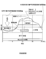
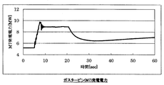
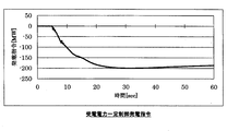
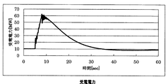
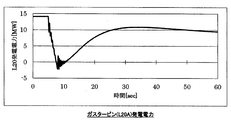
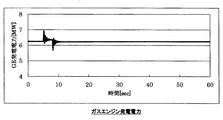
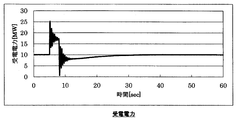
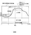
- the graph which showed the time-dependent change of electric power demand, and a power supply structure for demonstrating the electric power supply system shown in FIG. The graph which showed the simulation result (frequency) of case 1A as an Example of this invention.
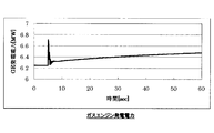
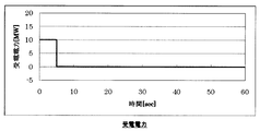
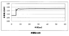
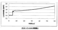
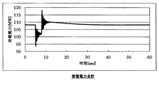
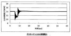
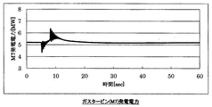
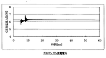
- the graph which showed the simulation result (total power generation) of case 2B as a comparative example of this invention The graph which showed the simulation result (gas turbine (L20A) generated electric power) of case 2B as a comparative example of this invention.
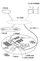
- FIGS. 1 and 2 a power supply system and a construction method thereof according to an embodiment of the present invention will be described with reference to FIGS. 1 and 2.
- the power supply system includes a centralized power generation facility (first power supply facility) 2 installed outside a plurality of target areas 1.
- the centralized power generation facility 2 is configured by a power generation device using at least one power generation method among nuclear power generation, thermal power generation, and large-scale hydropower generation.
- the power supply system includes a distributed power generation facility (second power supply facility) 3 installed inside each of the plurality of target areas 1.
- the distributed power generation facility 3 includes a plurality of power generation devices having different power generation methods, and at least a part of them may be configured by a power generation device that uses renewable energy.
- solar power generation solar thermal power generation, wind power generation, biomass energy-based power generation, gas turbine power generation, gas engine power generation, diesel engine power generation, wave power generation, ocean temperature difference power generation, small and medium-scale hydropower generation, geothermal power generation, hot spring
- a power generation apparatus using a power generation method such as thermal power generation, snow / ice heat power generation, ocean current / tidal current power generation, tidal power power generation, thermoelectric power generation, piezoelectric power generation, and exhaust heat power generation power generation can be used as the distributed power generation facility 3.
- a plurality of power generation apparatuses having different power generation methods constituting the distributed generation facility 3 installed in each target area 1 are configured to supply power to a common power demand destination existing in the target area 1 You may do it.
- a power storage device (second power supply facility) is installed inside the target area 1. ) 5 is installed.
- the power supply system includes a power transmission network 4 for sending power from the centralized power generation facility 2.
- the power transmission network 4 is connected to an internal power system (regional system) 7 laid in the target area 1 via a power transmission line 6 at a power receiving point.
- the power supply system includes an internal power control device 8 for stabilizing the internal power system 7 in the target area 1.
- the power that can be supplied from the external power system (commercial system) 9 including the centralized power generation facility 2, the power transmission network 4, and each transmission line 6 to the internal power system 7 is It is smaller than the power required to satisfy the peak power demand in each target area 1.
- the transmission capacity of each transmission line 6 cannot correspond to the peak power demand in each target area 1
- the transmission capacity of the power transmission network 4 cannot correspond to the peak power demand in the plurality of target areas 1 as a whole.
- the power generation capacity of the centralized power generation facility 2 cannot meet the peak power demand in the entire plurality of target areas 1.
- the distributed power generation facility 3 and the power storage device 5 described above have a power supply capability that can stabilize the internal power system 7 in the target area 1 in response to sudden power demand fluctuations in the target area 1. Yes.
- the internal power control device 8 measures the received power and frequency of the internal power system 7 and the fluctuation thereof at the power reception point from the power transmission line 6, and connects to the external power system 9 based on the measurement result. It has a received power constant control function for stabilizing the power system 7.
- the internal power control device 8 has a function of disconnecting the internal power system 7 from the external power system 9 when it is determined that the fluctuation of the frequency exceeds a predetermined threshold.
- the internal power control device 8 receives power from the external power system 9 while monitoring the state of the external power system 9 from the frequency variation and / or rate of change at the power reception points of the external power system 9 and the internal power system 7.
- a power supply increase command or a power supply decrease command is issued to the distributed power generation equipment 3 and the power storage device 5 in the target area 1 so as to keep the power constant and not exceed the allowable value according to the capacity of the power transmission line 6 ( Received power constant control).
- Received power constant control Received power constant control
- the distributed generation facility 3 Will bear.
- Examples of changes in the received power of the external power system 9 at the power reception points of the external power system 9 and the internal power system 7 include the following two patterns, for example.
- External power that is usually 10 MW due to a decrease in the power generated by the distributed generation facility 3 due to an increase in demand in the target area 1 or the generator of the distributed generation facility 3 being stopped (tripped) due to a failure, etc.
- the received power from the grid 9 is 10.02 MW.
- the received power from the external power system 9 which is usually 10 MW is 9.98 MW, for example.
- a command to reduce power supply is issued from the internal power control device 8 to the distributed power generation equipment 3 and the power storage device 5 in the target area 1 so as to keep the received power from the external power system 9 at 10 MW.
- a power supply increase command is issued from the internal power control device 8 to the distributed power generation equipment 3 and the power storage device 5 in the target area 1 so as to keep the received power from the external power system 9 at 10 MW.
- the internal power control device 8 since the frequency fluctuation of the external power system 9 is large, the generated power of the distributed power generation equipment 3 of the internal power system 7 fluctuates due to the influence (droop characteristic). And since the received power from the external power system 9 fluctuates due to the fluctuation of the generated power of the distributed power generation facility 3, the internal power control device 8 also controls this.
- Examples of changes in the frequency of the external power system 9 at the power reception point between the external power system 9 and the internal power system 7 include the following patterns.
- the power demand in the target area 1 increases from the centralized power generation facility 2 to the power transmission network 4 or the power transmission line 6 due to an increase in power consumption due to an increase in production in the industrial park or an increase in power consumption due to an increase in air conditioning demand in the village.
- the internal power control device 8 instructs the distributed power generation equipment 3 and / or the power storage device 5 to supply the shortage of power for the power demand. Send.
- the power generation amount of the distributed power generation facility 3 and / or the charge / discharge amount of the power storage device 5 is adjusted, including the start-up operation of the distributed power generation facility 3 and / or the charge / discharge operation of the power storage device 5.
- the internal power control device 8 includes the operation of stopping the power generation device 3 and / or the operation of charging / discharging the power storage device 5, including the power generation device 3. The power generation amount and / or the discharge amount from the power storage device 5 are adjusted.
- the internal power control device 8 further functions to disconnect the internal power system 7 in the target area 1 from the external power system 9 (system disconnection) when the external power system 9 is abnormal (sudden trip or the like) to make it an independent system.
- the internal power system 7 that has become a self-supporting system has a function of adjusting the power generated by the distributed power generation facility 3 and stabilizing the voltage and frequency. These functions will be described later.
- the actual power demand in the target area 1 exceeds the power that can be supplied from the centralized power generation facility 2 to the target area 1 via the power transmission network 4 and the power transmission line 6.
- the shortage of electric power is compensated by electric power from the distributed power generation equipment 3 and / or the power storage device 5 installed in the target area 1 according to a command from the internal power control device 8.
- the external power system itself already has sufficient power supply capability, so that it does not become unstable itself, and the distributed power generation device does not connect the internal power system in the target area. There is no stabilization.
- the power supply capacity from the external power system 9 (centralized power generation facility 2, power transmission network 4, power transmission line 6) 1 is set to a level that cannot meet the peak power demand, and the internal power system is supplied by supplying insufficient power from the distributed power generation equipment 3 and / or the power storage device 5 according to a command from the internal power control device 8. 7 is being stabilized.
- the power supplied from the centralized power generation facility 2 and the power supplied from the distributed power generation facility 3 and / or the power storage device 5 are combined efficiently, or a plurality of power generations constituting the distributed power generation facility 3
- various smart technologies in a smart grid such as a smart meter can be applied.
- a “smart meter” is a high-function power meter that has a communication function and a management function for other devices. For example, data such as power consumption is exchanged between power companies and consumers. Or connected to a consumer electronics device or the like to control it.
- “smart grid (next-generation power transmission network)” refers to a power transmission / distribution network that uses IT to optimize power supply and demand and realize stable power supply.
- the power supply capacity of the external power system 9 is set to a low level lower than the peak power demand in the target area 1 and is distributed in the target area 1. Since the power generation facility 3 and the power storage device 5 are installed, it is possible to appropriately cope with an increase in peak power demand in the target area 1 while suppressing an increase in the construction / maintenance cost of the power transmission / reception infrastructure (external power system 9).
- the power supply system and its construction method according to the present embodiment are extremely effective even in emerging countries where fragile power transmission networks are laid. Can be dealt with appropriately.
- the distributed power generation facility 3 and / or the power storage device 5 can cope with the peak while ensuring a stable base load in the centralized power generation facility 2.
- the internal power system 7 can be stably operated.
- a distributed power generation facility mainly for peak response 3 and / or an operation method of using the power storage device 5 is also possible.
- the power generation capacity of the centralized power generation facility 2, the power transmission capacity of the power transmission network 4, and / or the power transmission capacity of the power transmission line 6 can be suppressed to a level that can cover the base load necessary for maintaining the social infrastructure.
- the construction and maintenance costs of the power generation and transmission infrastructure can be reduced.
- the internal power system (regional system) 7 is connected to the external power system (commercial system) 9 at 50 Hz.
- the frequency fluctuation exceeds a predetermined threshold at a time point of 5 seconds from the state of interconnected operation (for example, a partial trip of a large-scale power plant).
- an absolute change amount or change rate of the frequency can be used as the threshold value of the frequency fluctuation.
- the internal power control device 8 on the internal power system (regional system) 7 side judges this, and disconnects the external power system (commercial system) 9 (for 5 seconds). System disconnection at the time), and simultaneously disconnect the interconnection mode. Then, the internal power control device 8 controls the distributed power generation facility 3 while performing the self-sustained operation in the internal power system 7.
- the heat load in the target area 1 does not affect the power generation amount of the steam turbine by starting a separate boiler instead of the steam turbine and causing the boiler to bear the load. Following these, measures can be taken to reduce the load itself in order to reduce the power demand in the target area 1.
- the drop or rise of the commercial system frequency is 2.5 Hz
- the drop is caused by a 10% output drop due to a generator trip in the centralized power generation facility 2, and the increase is supplied from the centralized power generation facility 2.
- the load of the centralized power generation facility 2 is reduced by 10% due to a power failure in another target area 1 to be received.
- the received power is up to 60 MW in the case 2B (25 MW with control, case 4). Although it rises, it cannot cope with this fluctuation in received power due to insufficient capacity of the transmission line.
- Case 2A (comparative example) shown in FIGS. 4A to 4G shows a case where the autonomous operation is performed in the interconnection mode without switching from the interconnection mode to the autonomous mode after the frequency fluctuation occurs. .
- the power supply system is not stable.
- case 1A (example) shown in FIGS. 3A to 3G is based on the premise that the mode is switched instantaneously after the disconnection
- case 3A (example) shown in FIGS. 5A-5G is The case where the mode is switched in 1 second after the release is shown.
- the internal power system (regional system) 7 can be stabilized even if mode switching takes some time.
- Target area 2 Centralized power generation facility (first power supply facility) 3 Distributed power generation facilities (second power supply facilities) 4 Power transmission network 5 Power storage device (second power supply facility) 6 Transmission lines (such as service lines) 7 Internal power system (regional system) 8 Internal power control device 9 External power system (commercial system)
Landscapes
- Engineering & Computer Science (AREA)
- Power Engineering (AREA)
- Supply And Distribution Of Alternating Current (AREA)
Abstract
本システムは、対象地域1外部の第一電源設備2と、第一電源設備2から電力を送る送電網と4、送電網4と対象地域内の内部電力系統7とを連絡する送電ライン6と、対象地域1内部の第二電源設備3と、内部電力系統7の給電状態を安定化させる内部電力制御装置8とを備える。第一電源設備2と送電網4と送電ライン6とを含む外部電力系統9から内部電力系統7に供給可能な電力が、対象地域1におけるピーク電力需要よりも小さい。内部電力制御装置8は、内部電力系統7の電圧・周波数の計測結果に基づいて、内部電力系統7における給電状態が安定するよう第二電源設備3の給電量を調整する。送電インフラの建設・維持コストを抑えつつ、対象地域における電力需要に適切に対応できる電力供給システムを提供することができる。
Description
本発明は、対象地域に電力を供給するための電力供給システム及びその構築方法に係り、特に、社会基盤(インフラストラクチャー)としての電力供給システム及びその構築方法に関する。
従来、先進国における発電送電インフラ(電力系統)においては、電力供給の対象地域におけるピーク電力需要を予め予測して、そのピーク電力需要に十分に対応できるように、当該ピーク電力を上回る発電容量を有する集中型発電設備を設置するようにしている(図10参照)。
例えば、図10に示した例においては、昼過ぎから夕方にかけて電力需要がピークに達しているが、集中型発電設備の発電容量はこのピーク電力を上回っている。
そのような集中型発電設備としては、例えば、原子力発電所や火力発電所、或いは大規模な水力発電所等があげられる。
また、原子力発電所等の集中型発電設備は、立地条件(冷却水の確保等)や用地購入費用等を考慮して、人口密集地(即ち、大規模な電力需要先)から遠く離れた場所に設置されるのが一般的である。
このように集中型発電設備は、一般に人口密集地から遠く離れた場所に設置されるので、集中型発電設備と人口密集地との間を連絡するために、大きな送電容量を持つ頑強な送電網及び送電ライン(引き込み線等)を、長距離にわたって敷設する必要がある。このような大規模な送電網及び送電ラインにおいては、その建設・維持コストが莫大なものとなっている。
また、近年、アジアやアフリカ、南米などの新興国においては、産業化の進行により、中心部の都市エリアのみならず、地方エリアでも電力需要が高まってきている。
しかしながら、一般に新興国においては、石炭火力発電等の集中型発電設備と地方エリアとを連絡する送電網及び送電ラインが脆弱である。このため、地方エリアでの増大したピーク電力需要を満たすために必要な電力を、既設の送電網及び送電ラインを介して集中型発電設備から当該地方エリアに対して十分に安定供給することができない状況にある。
新興国の地域によっては、中心部の都市エリアでさえも停電が頻発している状況であるが、地方エリアにおいては、中心部で発電所を建設しても電力を安定供給できない事態が発生している。
新興国におけるこのような状況を解決するための一つの方策には、集中型発電設備の発電容量を増大させ、既設の脆弱な送電網及び送電ラインも強化して、集中型発電設備から対象地域への電力供給量を増大させる方法がある。
しかし、この場合、新興国において必要な電力を各エリアに十分に安定供給するためには、既存の送電網及び送電ラインの強化や集中型発電設備の追加設置などが必要であり、そのために莫大な建設・維持コストがかかってしまう。
特許文献1に記載の技術は、スマートグリッド(地域系統)の監視制御方法において、「商用電力系統の周波数制御能力を算出し」、その情報から地域系統と商用電力系統の連系又は単独運転を判別するとしている。
この場合、周波数制御能力の算出には商用系統における総需要のデータが必要であり、この総需要データを商用系統の管理者(電力会社)から入手することが前提となる。そのため、特許文献1に記載の技術では、連系又は単独運転とするか否かは地域系統側で決定することはできない。
また、特許文献2は、地域系統と(不安定な)商用電力系統を連系させ、同時同量の電力供給を行うための周波数制御に関するものである。しかしながら、特許文献2には、実際に新興国において地域系統を整備する際の以下の問題点の指摘と解決策については、何ら提示はなされていない。
(1)新興国においては、送電網や送電ラインの容量が小さく、周波数変動に対する余裕が少ないこと。
(2)送電網や送電ラインの容量が小さいため周波数制御では対応できない場合に、如何にして地域系統の自立運転へ切り替えるか、自立運転の成立性に関する解決策。
(2)送電網や送電ラインの容量が小さいため周波数制御では対応できない場合に、如何にして地域系統の自立運転へ切り替えるか、自立運転の成立性に関する解決策。
本発明は、上述した従来の問題点を考慮して成されたものであって、発電送電インフラ(電力系統)の建設・維持コストの増加を抑えつつ、対象地域における電力需要の増加に適切に対応できる電力供給システム及びその構築方法を提供することを目的とする。
本発明は、特に新興国において、既存の脆弱で不安定な発電送電インフラ(電力系統)を活用し、低いコストで、対象地域にエネルギーを安定供給できる電力供給システム及びその構築方法を提供することを目的とする。
上記課題を解決するために、本発明は、対象地域に電力を供給するための電力供給システムにおいて、前記対象地域の外部に設置された第一電源設備と、前記第一電源設備からの電力を送るための送電網と、前記送電網と前記対象地域内に敷設された内部電力系統とを連絡する送電ラインと、前記対象地域の内部に設置された第二電源設備と、前記内部電力系統の給電状態を安定化させるための内部電力制御装置と、を備え、前記第一電源設備と前記送電網と前記送電ラインとを含む外部電力系統から前記内部電力系統に供給可能な電力が、前記対象地域におけるピーク電力需要を満たすために必要な電力よりも小さく、前記内部電力制御装置は、前記内部電力系統の受電電力及び周波数の計測結果に基づいて、前記内部電力系統における給電状態が安定するように前記第二電源設備からの給電量を調整する機能を有している、ことを特徴とする。
また、好ましくは、前記内部電力制御装置は、前記周波数の変動が所定の閾値を超えたと判断した場合に、前記内部電力系統を前記外部電力系統から切り離す機能を有している。
また、好ましくは、前記第一電源設備は、集中型発電設備を含む。
また、好ましくは、前記第二電源設備は、分散型発電設備を含む。
また、好ましくは、前記送電ラインは、前記対象地域におけるピーク電力需要を下回る送電容量を有している。
また、好ましくは、前記第二電源設備は、前記対象地域における電力需要が、前記外部電力系統から前記対象地域に供給できる電力を上回ったときに、前記内部電力制御装置からの指令を受けて、その不足分の電力を供給するように構成されている。
また、好ましくは、前記第一電源設備は、前記送電網及び前記送電ラインを介して複数の前記対象地域に電力を供給するように構成されている。
また、好ましくは、前記第二電源設備は、複数の前記対象地域のそれぞれに設置されている。
また、好ましくは、前記第二電源設備は、発電方式の異なる複数の発電装置を備えている。
また、好ましくは、前記発電方式の異なる複数の発電装置は、前記対象地域内の共通の電力需要先に対して電力を供給できるように構成されている。
また、好ましくは、前記第二電源設備は、再生可能エネルギーを利用する発電装置を有する。
また、好ましくは、前記第一電源設備は、原子力発電、火力発電、大規模水力発電のうちの少なくとも1つの発電方式による発電装置を含む。
また、好ましくは、前記第二電源設備は、太陽光発電、太陽熱発電、風力発電、バイオマスエネルギー利用発電、ガスタービン発電、ガスエンジン発電、ディーゼルエンジン発電、波力発電、海洋温度差発電、中小規模水力発電、地熱発電、温泉熱発電、雪氷熱利用発電、海流・潮流発電、潮汐力発電、熱電発電、圧電発電、排熱利用発電のうちの少なくとも1つの発電方式による発電装置を含む。
また、好ましくは、前記第二電源設備は、前記第一電源設備及び前記第二電源設備の少なくとも一方で生成された電力を貯蔵するために設置された蓄電装置をさらに有する。
また、好ましくは、前記蓄電装置は、前記対象地域の内部に設置されている。
上記課題を解決するために、本発明は、対象地域に電力を供給するための電力供給システムを構築するための方法において、前記対象地域の外部に第一電源設備を設置する工程と、前記第一電源設備からの電力を送るための送電網を設ける工程と、前記送電網と前記対象地域内に設けられた内部電力系統とを連絡する送電ラインを設ける工程と、前記対象地域の内部に第二電源設備を設置する工程と、前記内部電力系統の給電状態を安定化させるための内部電力制御装置を設ける工程と、を備え、前記第一電源設備と前記送電網と前記送電ラインとを含む外部電力系統から前記内部電力系統に供給可能な電力が、前記対象地域におけるピーク電力需要を満たすために必要な電力よりも小さく、前記内部電力制御装置は、前記内部電力系統の受電電力及び周波数の計測結果に基づいて、前記内部電力系統における給電状態が安定するように前記第二電源設備からの給電量を調整する機能を有している、ことを特徴とする。
また、好ましくは、前記内部電力制御装置は、前記周波数の変動が所定の閾値を超えたと判断した場合に、前記内部電力系統を前記外部電力系統から切り離す機能を有している。
また、好ましくは、前記第一電源設備は、集中型発電設備である。
また、好ましくは、前記第二電源設備は、分散型発電設備である。
また、好ましくは、前記外部電力系統は、前記対象地域におけるピーク電力需要を下回る給電容量を有している。
また、好ましくは、前記第二電源設備は、前記対象地域における電力需要が、前記外部電力系統から前記対象地域に供給できる電力を上回ったときに、前記内部電力制御装置からの指令を受けて、その不足分の電力を供給するように構成されている。
本発明による電力供給システム及びその構築方法によれば、発電送電インフラ(外部電力系統)の建設・維持コストの増加を抑えつつ、対象地域におけるピーク電力需要の増加に適切に対応することができる
以下、本発明の一実施形態による電力供給システム及びその構築方法について、図1及び図2を参照して説明する。
図1に示したように、本実施形態による電力供給システムは、複数の対象地域1の外部に設置された集中型発電設備(第一電源設備)2を備えている。この集中型発電設備2は、例えば、原子力発電、火力発電、大規模水力発電のうちの少なくとも1つの発電方式による発電装置によって構成されている。
また、本実施形態による電力供給システムは、複数の対象地域1のそれぞれの内部に設置された分散型発電設備(第二電源設備)3を備えている。
この分散型発電設備3は、発電方式の異なる複数の発電装置を備えており、そのうちの少なくとも一部を、再生可能エネルギーを利用する発電装置によって構成しても良い。
具体的には、太陽光発電、太陽熱発電、風力発電、バイオマスエネルギー利用発電、ガスタービン発電、ガスエンジン発電、ディーゼルエンジン発電、波力発電、海洋温度差発電、中小規模水力発電、地熱発電、温泉熱発電、雪氷熱利用発電、海流・潮流発電、潮汐力発電、熱電発電、圧電発電、及び排熱利用発電等の発電方式による発電装置を、分散型発電設備3として使用することができる。
各対象地域1内に設置された分散型発電設備3を構成する発電方式の異なる複数の発電装置を、当該対象地域1内に存在する共通の電力需要先に対して電力を供給できるように構成しても良い。
また、本実施形態による電力供給システムにおいては、集中型発電設備2及び分散型発電設備3の少なくとも一方で生成された電力を貯蔵するために、対象地域1の内部に蓄電装置(第二電源設備)5が設置されている。
また、本実施形態による電力供給システムは、集中型発電設備2からの電力を送るための送電網4を備えている。この送電網4は、送電ライン6を介して、対象地域1内に敷設された内部電力系統(地域系統)7に、受電点において接続されている。
さらに、本実施形態による電力供給システムは、対象地域1の内部電力系統7を安定化させるための内部電力制御装置8を備えている。
そして、本実施形態による電力供給システムにおいては、集中型発電設備2と送電網4と各送電ライン6とを含む外部電力系統(商用系統)9から、内部電力系統7に供給可能な電力が、各対象地域1におけるピーク電力需要を満たすために必要な電力よりも小さい。
具体的な態様としては、各送電ライン6の送電容量が、各対象地域1におけるピーク電力需要に対応できない場合、送電網4の送電容量が、複数の対象地域1全体におけるピーク電力需要に対応できない場合、及び/又は、集中型発電設備2の発電容量が、複数の対象地域1全体におけるピーク電力需要に対応できない場合があげられる。
上述の分散型発電設備3及び蓄電装置5は、当該対象地域1における急激な電力需要変動にも対応して、対象地域1の内部電力系統7を安定化させることができる給電能力を有している。
そして、内部電力制御装置8は、内部電力系統7の受電電力及び周波数とその変動を送電ライン6からの受電点において計測し、その計測結果に基づいて、外部電力系統9と連系しつつ内部電力系統7を安定化させるための受電電力一定制御機能を有している。
また、内部電力制御装置8は、前記周波数の変動が所定の閾値を超えたと判断した場合に、内部電力系統7を外部電力系統9から切り離す機能を有している。
つまり、内部電力制御装置8は、外部電力系統9と内部電力系統7との受電点における周波数の変動および/又は変化率から外部電力系統9の状態を監視しつつ、外部電力系統9からの受電電力を一定に保ち、送電ライン6の容量に応じた許容値を超えないように、対象地域1内の分散型発電設備3や蓄電装置5に対して、給電増加指令又は給電減少指令を行う(受電電力一定制御)。これにより、対象地域1内の電力需給の同時同量が図られ、電力安定化を実現することができる。
一例としては、外部電力系統9からの受電電力として10MWを想定し、内部電力系統7の需要のピークを100MW程度と想定した場合、対象地域1内の大部分の電力を分散型発電設備3が担うことになる。
以下、内部電力制御装置8による受電電力の変化への対応について説明する。
外部電力系統9と内部電力系統7との受電点における外部電力系統9の受電電力が変化する例としては、例えば以下の2つのパターンがあげられる。
i) 対象地域1内の需要増又は分散型発電設備3の発電機が故障等により停止(トリップ)することにより、分散型発電設備3の発電電力の減少などを受け、通常10MWである外部電力系統9からの受電電力が例えば10.02MW等となる。
ii) 対象地域1内の需要減を受け、受電電力が減少する場合、通常10MWである外部電力系統9からの受電電力が例えば9.98MWとなる。
そして、上記2つのパターンにおける給電指令の考え方は以下の通りである。
例えば上記i)において、外部電力系統9からの受電電力を10MWに保つよう、内部電力制御装置8から対象地域1内の分散型発電設備3や蓄電装置5に対して給電減少指令を行う。
また上記ii)において、外部電力系統9からの受電電力を10MWに保つよう、内部電力制御装置8から対象地域1内の分散型発電設備3や蓄電装置5に対して給電増加指令を行う。
ここで、外部電力系統9の周波数変動が大きい場合には、その影響により、内部電力系統7の分散型発電設備3の発電電力が変動してしまう(ドループ特性)。そして、この分散型発電設備3の発電電力の変動により、外部電力系統9からの受電電力が変動するので、内部電力制御装置8はこれに対する制御も行う。
次に、内部電力制御装置8による周波数の変化への対応について説明する。
外部電力系統9と内部電力系統7との受電点における外部電力系統9の周波数が変化する例としては、例えば以下のパターンがあげられる。
i) 外部電力系統9の周波数が低下することにより、分散型発電設備3の発電電力がドループ特性により増加し、結果、受電電力が減少する場合。
ii) 外部電力系統9の周波数が上昇することにより、分散型発電設備3の発電電力がドループ特性により減少し、結果、受電電力が増加する場合。
そして、上記パターンにおける給電指令の考え方は以下の通りである。
上記i)、ii)において、外部電力系統9の周波数が変化すると発電機の発電電力は変化する特性がある。周波数がΔf変動すると、分散型発電設備3の発電電力の変動ΔPgenはΔPgen=-Δf×Dr(Dr:ドループ3~5%)の関係があり、これに対応した外部電力系統9からの受電電力の増加ΔPinfはΔf×Drで計算できる。つまり、Δf×Drの電力を対象地域1内の分散型発電設備3や蓄電装置5から給電させることでこの受電電力の増加を抑えることができる。受電電力の減少を抑える場合も同じ要領で考える。
上記のような受電電力一定制御により内部電力系統7と外部電力系統9とで連系しつつ、外部電力系統9からの受電電力を超える内部電力系統7の需要増には以下のように対応する。
例えば、対象地域1における電力需要が、工業団地における生産増による電力消費量の増加や、集落における空調需要増による電力消費量の増加等によって、集中型発電設備2から送電網4・送電ライン6を介して対象地域1に供給できる電力を上回ったときには、内部電力制御装置8は、その電力需要に対する不足分の電力を供給するように分散型発電設備3及び/又は蓄電装置5に対して指令を送る。
これにより、分散型発電設備3の起動操作及び/又は蓄電装置5の充放電操作を含め、分散型発電設備3の発電量及び/又は蓄電装置5の充放電量が調整される。
一方、対象地域1における電力需要が、工業団地における生産減による電力消費量の減少や、集落における一時的な居住人口の減少(外出増)等によって、集中型発電設備2から送電網4・送電ライン6を介して対象地域1に供給できる電力を下回ったときには、内部電力制御装置8は、分散型発電設備3の停止操作及び/又は蓄電装置5の充放電操作を含め、分散型発電設備3の発電量及び/又は蓄電装置5からの放電量を調節する。
また、内部電力制御装置8は、更に外部電力系統9の異常時(急なトリップ等)に対象地域1の内部電力系統7を外部電力系統9から切り離し(系統解列)、自立系統とする機能も有す。加えて、自立系統となった内部電力系統7において、分散型発電設備3の発電電力を調整し、電圧、周波数を安定化させる機能も有している。これらの機能については後述する。
上記の通り、本実施形態による電力供給システムにおいては、対象地域1における実際の電力需要が、集中型発電設備2から送電網4・送電ライン6を介して対象地域1に供給できる電力を上回ったときには、内部電力制御装置8からの指令によって、対象地域1の内部に設置された分散型発電設備3及び/又は蓄電装置5からの電力によって、その不足分の電力が補填される。
従って、外部電力系統9からの受電電力のみでは対象地域1内のピーク電力需要を満たせない場合であっても、電力の需給バランスが崩れて内部電力系統7が不安定化し、停電が発生するようなことがなく、電力需給の同時同量を維持することができる。
なお、現在でも、ガスエンジンなどの分散型発電装置が事業所や工場などにおいて自家発電として用いられている例もあるが、この場合は、当該事業所や工場内の周波数の安定化は、外部電力系統9に依存しているのが一般的である。
即ち、この従来の例においては、外部電力系統自体が既に十分な電力供給能力を有しているので、それ自身が不安定になることはなく、分散型発電装置が対象地域の内部電力系統を安定化させることはない。
これに対して、本実施形態による電力供給システムにおいては、外部電力系統9(集中型発電設備2、送電網4、送電ライン6)からの給電能力を、この外部電力系統9のみでは各対象地域1のピーク電力需要に対応できないレベルに設定すると共に、内部電力制御装置8からの指令により、不足分の電力を、分散型発電設備3及び/又は蓄電装置5から供給することで、内部電力系統7の安定化を図っている。
なお、集中型発電設備2から供給される電力と、分散型発電設備3及び/又は蓄電装置5から供給される電力とを効率的に組み合わせ、或いは、分散型発電設備3を構成する複数の発電装置及び蓄電装置5からの電力を効率的に組み合わせるために、スマートメータなどスマートグリッド等における各種のスマート技術を適用することができる。
ここで、「スマートメータ」とは、通信機能や他の機器の管理機能を持つ高機能電力メーターのことであり、例えば電力会社と需要者の間をつないで電力使用量などのデータをやり取りしたり、需要先の家電製品などと接続してそれを制御したりすることができる。
また、「スマートグリッド(次世代送電網)」とは、ITを活用して電力需給の最適化を図り、電力の安定供給を実現するための送配電線網のことである。
以上述べたように、本実施形態による電力供給システムによれば、外部電力系統9の給電能力を、対象地域1におけるピーク電力需要を下回る低いレベルに設定すると共に、対象地域1の内部に分散型発電設備3及び蓄電装置5を設置したので、発電送電インフラ(外部電力系統9)の建設・維持コストの増加を抑えつつ、対象地域1におけるピーク電力需要の増加に適切に対応することができる。
とりわけ、本実施形態による電力供給システム及びその構築方法は、脆弱な送電網が敷設されている新興国においても極めて有効であり、発電送電インフラの投資額を低く抑えつつ、特に地方エリアにおける電力需要の増大に適切に対処することができる。
ここで、新興国における地方エリアは、山岳地帯や離島に存在する場合も多く、送電網の敷設には多大のコストがかかるため、既存の脆弱な送電網をそのまま活用できることのメリットは極めて大きい。
また、集中型発電設備2は電力を安定的に生成することができるので、集中型発電設備2で安定したベースロードを確保しつつ、ピーク時には分散型発電設備3及び/又は蓄電装置5で対応することで、自然条件によって出力が変動する再生可能エネルギーが分散型発電設備3の一部に入ったとしても、内部電力系統7を安定的に運用することができる。
例えば、集中型発電設備2からの電力によって、社会基盤(交通網、通信網等)を維持するためのベースロードを連続的かつ安定的に供給しつつ、主としてピーク対応のために分散型発電設備3及び/又は蓄電装置5を使用するという運用方法も可能である。
この場合も、集中型発電設備2の発電容量、送電網4の送電容量、及び/又は送電ライン6の送電容量を、社会基盤の維持に必要なベースロードをまかなえるレベルに抑えることができるので、発電送電インフラの建設・維持コストを抑制することができる。
以下、本発明による電力供給システムの実施例(ケース1A、3A)、及び比較例(ケース2A、1B-4B)のシミュレーション結果について、図3A乃至図9Hを参照して説明する。
ケース1A-3Aのシミュレーション条件を表1に示し、ケース1B-4Bのシミュレーション条件を表2に示す。

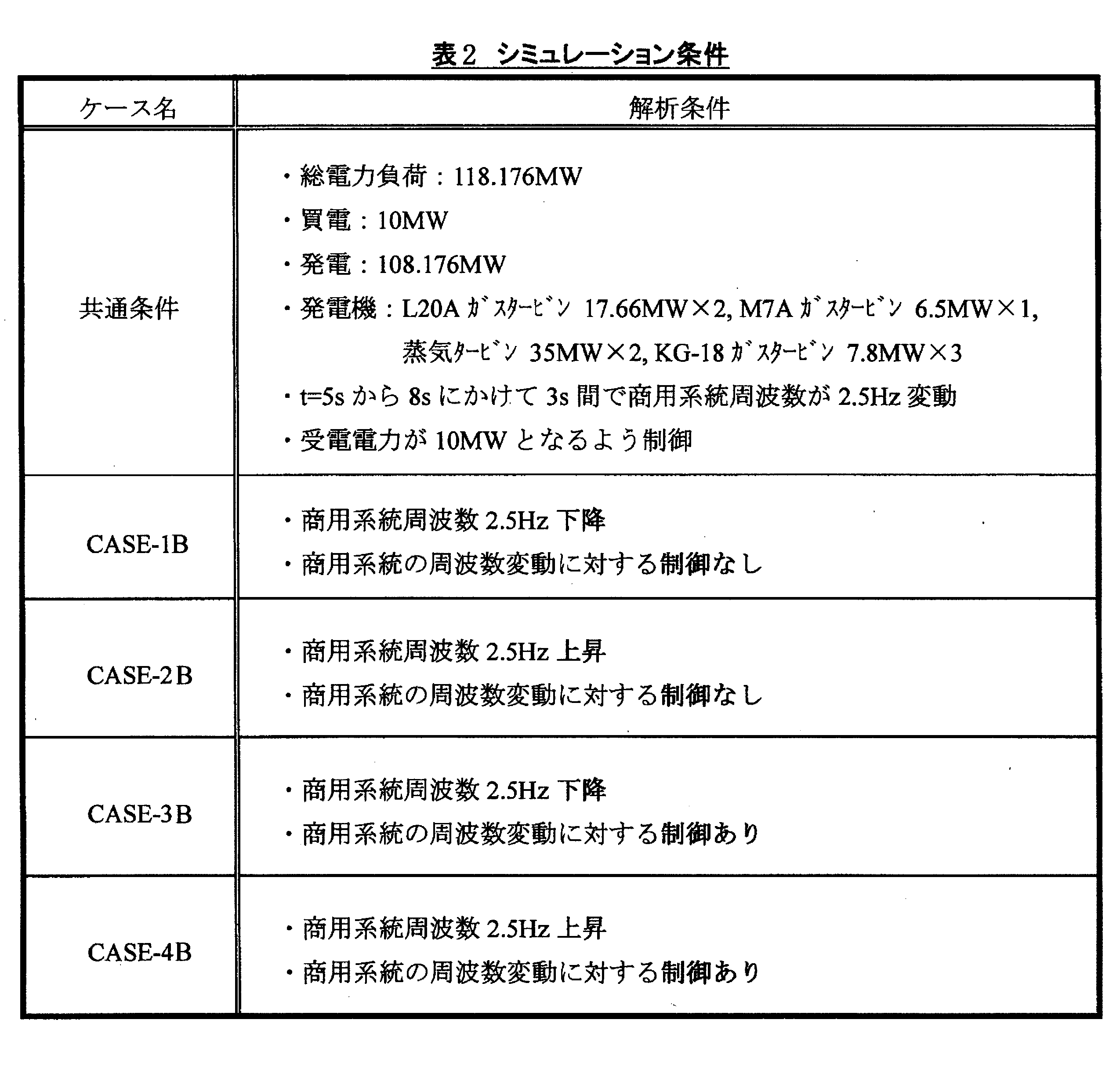
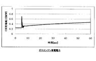
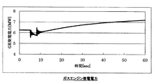
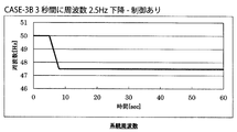
図3A-3Gに示したケース1A(実施例)及び図5A-5Gに示したケース3A(実施例)は、内部電力系統(地域系統)7が外部電力系統(商用系統)9と50Hzで系統連系運転している状態から、5秒の時点で周波数変動が所定の閾値を超えた場合(例えば大規模発電所の一部トリップなど)である。ここで、周波数変動の閾値としては、周波数の絶対的な変化量又は変化率を用いることができる。
このように周波数変動が所定の閾値を超えた場合、内部電力系統(地域系統)7側の内部電力制御装置8でこれを判断して、外部電力系統(商用系統)9を切り離し(5秒の時点で系統解列)、同時に連系モードも断ち切る。そして、内部電力制御装置8により、分散型発電設備3を制御しながら、内部電力系統7にて自立運転を行うものである。
自立運転に切り替わると、それまで外部電力系統(商用系統)9から受電していた電力を負担しなければならないので、内部電力系統7においてはその分のマージンを素早く確保する必要がある。
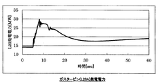
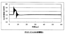
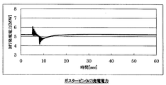
そこで、ケース1A、3A(実施例)においては、自立運転直後は、応答性能の良いガスタービンの発電量を上げることによって電力の不足分を当初カバーし(図3D-3E、図5D-5E)、その後は蒸気タービンやガスエンジンで順次カバーする(図3F-3G、図5F-5G)。
なお、対象地域1での熱負荷は、蒸気タービンでなく別途ボイラを起動させ、当該ボイラに負担させることで蒸気タービンの発電量に影響を及ぼさないようにするのが好ましい。これらに次いで対象地域1の電力需要を下げるべく負荷自体を下げる措置をとることもできる。
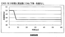
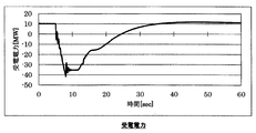
一方、図6A-9Hに示した比較例(ケース1B-4B)においては、商用系統周波数が2.5Hz下降又は上昇した場合、内部電力系統(地域系統)を外部電力系統(商用系統)から切り離すこと無く、ガスタービン等の分散型発電設備で対応している。
なお、商用系統周波数の下降又は上昇を2.5Hzとしたが、下降については集中型発電設備2における発電機トリップにより10%出力低下した場合を、上昇については集中型発電設備2から電力供給を受ける別の対象地域1の停電により集中型発電設備2の負荷が10%低下した場合を想定したものである。新興国では平時でも2%近い瞬時の周波数変動がみられ、上記のような集中型発電設備2のトリップ、別の対象地域1の停電があった場合、さらに大きな変動になることを考慮している。
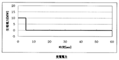
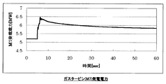
これらのケース(比較例)においては、図6B、図7B、図8B、図9Bから分かるように、受電電力の変動幅が大きいため、新興国などにおける脆弱な送電網及び送電ラインでは、この受電電力の変動に対応できない。
例えば、受電電力10MWで制御する場合、外部電力系統(商用系統)において2.5Hzの周波数上昇があった場合は、ケース2Bにおいては受電電力が60MW(制御ありの場合は25MW,ケース4)まで上昇するが、送電ラインの容量不足により、この受電電力の変動に対応できない。
また、図4A-4Gに示したケース2A(比較例)は、周波数変動が生じた後、連系モードから自立モードに切り替えずに、連系モードのまま自立運転を行った場合を示している。この場合、図4Aから分かるように、電源系統は安定しない。
なお、図3A-3Gに示したケース1A(実施例)は、解列後、瞬時にモードが切り替わることを前提にしており、一方、図5A-5Gに示したケース3A(実施例)は、解列後1秒でモードが切り替わる場合を示している。ケース3Aのシミュレーション結果から分かるように、モードの切り替えに多少時間がかかっても、内部電力系統(地域系統)7を安定化させることができる。
1 対象地域
2 集中型発電設備(第一電源設備)
3 分散型発電設備(第二電源設備)
4 送電網
5 蓄電装置(第二電源設備)
6 送電ライン(引き込み線等)
7 内部電力系統(地域系統)
8 内部電力制御装置
9 外部電力系統(商用系統)
2 集中型発電設備(第一電源設備)
3 分散型発電設備(第二電源設備)
4 送電網
5 蓄電装置(第二電源設備)
6 送電ライン(引き込み線等)
7 内部電力系統(地域系統)
8 内部電力制御装置
9 外部電力系統(商用系統)
Claims (21)
- 対象地域に電力を供給するための電力供給システムにおいて、
前記対象地域の外部に設置された第一電源設備と、
前記第一電源設備からの電力を送るための送電網と、
前記送電網と前記対象地域内に敷設された内部電力系統とを連絡する送電ラインと、
前記対象地域の内部に設置された第二電源設備と、
前記内部電力系統の給電状態を安定化させるための内部電力制御装置と、を備え、
前記第一電源設備と前記送電網と前記送電ラインとを含む外部電力系統から前記内部電力系統に供給可能な電力が、前記対象地域におけるピーク電力需要を満たすために必要な電力よりも小さく、
前記内部電力制御装置は、前記内部電力系統の受電電力及び周波数の計測結果に基づいて、前記内部電力系統における給電状態が安定するように前記第二電源設備からの給電量を調整する機能を有している、電力供給システム。 - 前記内部電力制御装置は、前記周波数の変動が所定の閾値を超えたと判断した場合に、前記内部電力系統を前記外部電力系統から切り離す機能を有している、請求項1記載の電力供給システム。
- 前記第一電源設備は、集中型発電設備を含む、請求項1又は2に記載の電力供給システム。
- 前記第二電源設備は、分散型発電設備を含む、請求項1乃至3のいずれか一項に記載の電力供給システム。
- 前記送電ラインは、前記対象地域におけるピーク電力需要を下回る送電容量を有している、請求項1乃至4のいずれか一項に記載の電力供給システム。
- 前記第二電源設備は、前記対象地域における電力需要が、前記外部電力系統から前記対象地域に供給できる電力を上回ったときに、前記内部電力制御装置からの指令を受けて、その不足分の電力を供給するように構成されている、請求項1乃至5のいずれか一項に記載の電力供給システム。
- 前記第一電源設備は、前記送電網及び前記送電ラインを介して複数の前記対象地域に電力を供給するように構成されている、請求項1乃至6のいずれか一項に記載の電力供給システム。
- 前記第二電源設備は、複数の前記対象地域のそれぞれに設置されている、請求項7記載の電力供給システム。
- 前記第二電源設備は、発電方式の異なる複数の発電装置を備えている、請求項1乃至8のいずれか一項に記載の電力供給システム。
- 前記発電方式の異なる複数の発電装置は、前記対象地域内の共通の電力需要先に対して電力を供給できるように構成されている、請求項9記載の電力供給システム。
- 前記第二電源設備は、再生可能エネルギーを利用する発電装置を有する、請求項1乃至10のいずれか一項に記載の電力供給システム。
- 前記第一電源設備は、原子力発電、火力発電、大規模水力発電のうちの少なくとも1つの発電方式による発電装置を含む、請求項1乃至11のいずれか一項に記載の電力供給システム。
- 前記第二電源設備は、太陽光発電、太陽熱発電、風力発電、バイオマスエネルギー利用発電、ガスタービン発電、ガスエンジン発電、ディーゼルエンジン発電、波力発電、海洋温度差発電、中小規模水力発電、地熱発電、温泉熱発電、雪氷熱利用発電、海流・潮流発電、潮汐力発電、熱電発電、圧電発電、排熱利用発電のうちの少なくとも1つの発電方式による発電装置を含む、請求項1乃至12のいずれか一項に記載の電力供給システム。
- 前記第二電源設備は、前記第一電源設備及び前記第二電源設備の少なくとも一方で生成された電力を貯蔵するために設置された蓄電装置をさらに有する、請求項1乃至13のいずれか一項に記載の電力供給システム。
- 前記蓄電装置は、前記対象地域の内部に設置されている、請求項14記載の電力供給システム。
- 対象地域に電力を供給するための電力供給システムを構築するための方法において、
前記対象地域の外部に第一電源設備を設置する工程と、
前記第一電源設備からの電力を送るための送電網を設ける工程と、
前記送電網と前記対象地域内に設けられた内部電力系統とを連絡する送電ラインを設ける工程と、
前記対象地域の内部に第二電源設備を設置する工程と、
前記内部電力系統の給電状態を安定化させるための内部電力制御装置を設ける工程と、を備え、
前記第一電源設備と前記送電網と前記送電ラインとを含む外部電力系統から前記内部電力系統に供給可能な電力が、前記対象地域におけるピーク電力需要を満たすために必要な電力よりも小さく、
前記内部電力制御装置は、前記内部電力系統の受電電力及び周波数の計測結果に基づいて、前記内部電力系統における給電状態が安定するように前記第二電源設備からの給電量を調整する機能を有している、電力供給システムの構築方法。 - 前記内部電力制御装置は、前記周波数の変動が所定の閾値を超えたと判断した場合に、前記内部電力系統を前記外部電力系統から切り離す機能を有している、請求項16記載の電力供給システムの構築方法。
- 前記第一電源設備は、集中型発電設備である、請求項16又は17に記載の電力供給システムの構築方法。
- 前記第二電源設備は、分散型発電設備である、請求項16乃至18のいずれか一項に記載の電力供給システムの構築方法。
- 前記外部電力系統は、前記対象地域におけるピーク電力需要を下回る給電容量を有している、請求項16乃至19のいずれか一項に記載の電力供給システムの構築方法。
- 前記第二電源設備は、前記対象地域における電力需要が、前記外部電力系統から前記対象地域に供給できる電力を上回ったときに、前記内部電力制御装置からの指令を受けて、その不足分の電力を供給するように構成されている、請求項16乃至20のいずれか一項に記載の電力供給システムの構築方法。
Applications Claiming Priority (2)
| Application Number | Priority Date | Filing Date | Title |
|---|---|---|---|
| JP2012287383A JP2014131389A (ja) | 2012-12-28 | 2012-12-28 | 電力供給システム及びその構築方法 |
| JP2012-287383 | 2012-12-28 |
Publications (1)
| Publication Number | Publication Date |
|---|---|
| WO2014104091A1 true WO2014104091A1 (ja) | 2014-07-03 |
Family
ID=51021169
Family Applications (1)
| Application Number | Title | Priority Date | Filing Date |
|---|---|---|---|
| PCT/JP2013/084651 Ceased WO2014104091A1 (ja) | 2012-12-28 | 2013-12-25 | 電力供給システム及びその構築方法 |
Country Status (2)
| Country | Link |
|---|---|
| JP (1) | JP2014131389A (ja) |
| WO (1) | WO2014104091A1 (ja) |
Cited By (1)
| Publication number | Priority date | Publication date | Assignee | Title |
|---|---|---|---|---|
| CN110661289A (zh) * | 2019-09-26 | 2020-01-07 | 深圳天顺智慧能源科技有限公司 | 微电网系统并网运行控制方法、装置以及微电网系统 |
Families Citing this family (5)
| Publication number | Priority date | Publication date | Assignee | Title |
|---|---|---|---|---|
| JP6086328B2 (ja) * | 2015-03-18 | 2017-03-01 | 中国電力株式会社 | 周波数制御方法 |
| JP6622552B2 (ja) * | 2015-10-19 | 2019-12-18 | 株式会社日立製作所 | 分散型電源の電力供給システム |
| JP6654327B2 (ja) * | 2016-05-30 | 2020-02-26 | 有限会社ネクサム | 発送電システム |
| JP7601694B2 (ja) * | 2021-04-14 | 2024-12-17 | 三菱重工パワーインダストリー株式会社 | バイオマス燃料利用システム |
| KR20250101212A (ko) * | 2023-12-27 | 2025-07-04 | 주식회사 앤솔루션 | 수상 태양광 발전의 전력 관제 장치 및 방법 |
Citations (3)
| Publication number | Priority date | Publication date | Assignee | Title |
|---|---|---|---|---|
| JPH10341530A (ja) * | 1997-06-05 | 1998-12-22 | Hitachi Ltd | 分散電源制御システム |
| JPH11299100A (ja) * | 1998-04-15 | 1999-10-29 | Hitachi Ltd | エネルギー・電力融通システム及びその融通方法 |
| JP2010213420A (ja) * | 2009-03-09 | 2010-09-24 | Toshiba Corp | 電力融通管理システムおよび電力融通管理プログラム |
-
2012
- 2012-12-28 JP JP2012287383A patent/JP2014131389A/ja active Pending
-
2013
- 2013-12-25 WO PCT/JP2013/084651 patent/WO2014104091A1/ja not_active Ceased
Patent Citations (3)
| Publication number | Priority date | Publication date | Assignee | Title |
|---|---|---|---|---|
| JPH10341530A (ja) * | 1997-06-05 | 1998-12-22 | Hitachi Ltd | 分散電源制御システム |
| JPH11299100A (ja) * | 1998-04-15 | 1999-10-29 | Hitachi Ltd | エネルギー・電力融通システム及びその融通方法 |
| JP2010213420A (ja) * | 2009-03-09 | 2010-09-24 | Toshiba Corp | 電力融通管理システムおよび電力融通管理プログラム |
Cited By (1)
| Publication number | Priority date | Publication date | Assignee | Title |
|---|---|---|---|---|
| CN110661289A (zh) * | 2019-09-26 | 2020-01-07 | 深圳天顺智慧能源科技有限公司 | 微电网系统并网运行控制方法、装置以及微电网系统 |
Also Published As
| Publication number | Publication date |
|---|---|
| JP2014131389A (ja) | 2014-07-10 |
Similar Documents
| Publication | Publication Date | Title |
|---|---|---|
| US12224583B2 (en) | Highly flexible, electrical distribution grid edge energy manager and router | |
| US11652365B2 (en) | Highly flexible electrical distribution grid edge energy manager and router | |
| JP5553390B2 (ja) | 交流の自律分散型の電力システム | |
| Sayed et al. | SCADA and smart energy grid control automation | |
| JP5100009B2 (ja) | 電力システム | |
| US8140194B2 (en) | Supply-and-demand control system of distributed and coordinated type, for use in power systems | |
| JPWO2008047400A1 (ja) | 電力システム | |
| JPWO2008117392A1 (ja) | 電力システム | |
| US20130015703A1 (en) | Microgrid | |
| WO2014104091A1 (ja) | 電力供給システム及びその構築方法 | |
| JP2011083086A (ja) | 電力分配システム | |
| KR101109187B1 (ko) | 실시간 전력정보를 이용한 전력계통의 운영방법 | |
| JP2017521034A (ja) | 送電網ネットワークのゲートウェイアグリゲーション | |
| Hatziargyriou et al. | The kythnos microgrid: A 20-year history | |
| CN101473507B (zh) | 功率补偿器及通过该补偿器提供黑启动的方法 | |
| JP2012005310A (ja) | 新エネルギー発電所群の制御システム、およびその制御方法 | |
| US9281693B2 (en) | System control apparatus for equipment | |
| Penkey et al. | Sizing and location identification for an electrical energy storage system in a renewable microgrid | |
| JP2011135768A (ja) | 電力供給装置、及び、インバータ装置 | |
| JP6936071B2 (ja) | 発電設備の制御方法および発電設備の制御装置 | |
| JPWO2015049844A1 (ja) | パワーマネジメントユニットおよびパワーマネジメント方法 | |
| Moulema et al. | Integrating Renewable Energy Resources in Smart Grid Toward Energy-Based Cyber-Physical Systems | |
| Deveikis et al. | Reliability of divided small electric energy system | |
| JP6514384B2 (ja) | 電力管理システム、電力管理方法、電力制御装置及び燃料電池装置 | |
| Robyns et al. | Supervision of renewable energy for its integration in the electrical system |
Legal Events
| Date | Code | Title | Description |
|---|---|---|---|
| 121 | Ep: the epo has been informed by wipo that ep was designated in this application |
Ref document number: 13869395 Country of ref document: EP Kind code of ref document: A1 |
|
| NENP | Non-entry into the national phase |
Ref country code: DE |
|
| 122 | Ep: pct application non-entry in european phase |
Ref document number: 13869395 Country of ref document: EP Kind code of ref document: A1 |