WO2014104077A1 - 熱流束センサ及び熱流束センサの製造方法 - Google Patents
熱流束センサ及び熱流束センサの製造方法 Download PDFInfo
- Publication number
- WO2014104077A1 WO2014104077A1 PCT/JP2013/084624 JP2013084624W WO2014104077A1 WO 2014104077 A1 WO2014104077 A1 WO 2014104077A1 JP 2013084624 W JP2013084624 W JP 2013084624W WO 2014104077 A1 WO2014104077 A1 WO 2014104077A1
- Authority
- WO
- WIPO (PCT)
- Prior art keywords
- main body
- heat flux
- flux sensor
- perforations
- heat
- Prior art date
- Legal status (The legal status is an assumption and is not a legal conclusion. Google has not performed a legal analysis and makes no representation as to the accuracy of the status listed.)
- Ceased
Links
Images

Classifications
-
- G—PHYSICS
- G01—MEASURING; TESTING
- G01K—MEASURING TEMPERATURE; MEASURING QUANTITY OF HEAT; THERMALLY-SENSITIVE ELEMENTS NOT OTHERWISE PROVIDED FOR
- G01K17/00—Measuring quantity of heat
- G01K17/06—Measuring quantity of heat conveyed by flowing media, e.g. in heating systems e.g. the quantity of heat in a transporting medium, delivered to or consumed in an expenditure device
- G01K17/08—Measuring quantity of heat conveyed by flowing media, e.g. in heating systems e.g. the quantity of heat in a transporting medium, delivered to or consumed in an expenditure device based upon measurement of temperature difference or of a temperature
- G01K17/20—Measuring quantity of heat conveyed by flowing media, e.g. in heating systems e.g. the quantity of heat in a transporting medium, delivered to or consumed in an expenditure device based upon measurement of temperature difference or of a temperature across a radiating surface, combined with ascertainment of the heat transmission coefficient
Definitions
- the present invention relates to a heat flux sensor that measures a heat flux that is an amount of heat that crosses a unit area of a measurement target unit per unit time, and a method for manufacturing the heat flux sensor.
- the tip of a flying object traveling at an ultra-high speed is aerodynamically heated by a shock wave, and the temperature rises and is exposed to a high temperature.
- a shock wave For example, it is known that the tip of a flying object traveling at an ultra-high speed is aerodynamically heated by a shock wave, and the temperature rises and is exposed to a high temperature.
- thermocouples As a heat flux sensor for measuring a temperature state, a method of attaching a rod-shaped member in which two thermocouples are embedded in a measurement target part is known (see, for example, Patent Document 1).
- thermocouples when measuring the heat flux by the above-described method, there is a problem that a heat flux error occurs unless the two thermocouples are accurately fixed to the wall surface of the measurement target portion. That is, the hot junctions of the two thermocouples are not arranged on the same normal line at a predetermined position on the wall surface, and an error in the heat flux is likely to occur due to a shift in the mounting position.
- thermocouples such as the heat flux sensor described above
- An object of the present invention is to provide a heat flux sensor and a method of manufacturing the heat flux sensor that can prevent the occurrence of a heat flux error due to a shift of the thermometer side position.
- the heat flux sensor is a heat flux sensor attached to a hole formed in the surface of the measurement object, and an outer peripheral surface facing the inner peripheral surface of the hole.
- a plurality of perforations arranged on the normal line are formed, arranged so as to contact the tip of each of the perforations, and a plurality of thermal sensors that reach the outer surface of the main body via the perforations, and the perforations And a filler for sealing the thermal sensor in the perforations.
- the heat sensor is arranged in the previously formed perforations and the heat sensor is fixed by the filler, it is possible to prevent the occurrence of a heat flux error due to the shift of the thermometer side position. Moreover, since it is the structure which attaches the main-body part to which the several heat sensor was fixed to the hole of a measuring object, arrangement
- heat flux sensor three or more heat sensors may be provided.
- the heat flux error can be reduced by calculating the heat flux from three or more temperatures.
- the main body may have a cylindrical shape, and the tip of the heat sensor may be disposed on a central axis of the main body.
- the thermal sensor since the position of the thermal sensor can be determined by the depth of the perforation, the thermal sensor can be easily positioned.
- the heat flux sensor may have a configuration in which a filler is filled between the holes.
- the perforations may be provided at equal intervals in the circumferential direction of the main body.
- the heat flux sensor may include a cylindrical pipe portion provided so as to cover an outer peripheral surface of the main body portion, and a filler may be filled between the main body portion and the pipe portion. Good.
- the material of the sensor and the pipe portion may be the same as that of the measurement object.
- an oxide film may be formed on the front end surface.
- the state of the front end surface of the main body is the same as that of the surface of the object to be measured, so that the heat flux error can be further reduced.
- the present invention provides a main body having a step of forming a hole in the surface of the measurement object, an outer peripheral surface facing the inner peripheral surface of the hole, and a front end surface flush with the surface of the measurement object. And forming a plurality of perforations in the main body portion extending from the outer surface other than the front end surface of the main body portion toward the inside, each having a tip disposed on the same normal line of the front end surface; Arranging a plurality of heat sensors so as to contact the tip of each of the perforations, wiring the wiring so as to reach the outer surface of the main body through the perforations, and sealing the heat sensors in the perforations. And a step of filling the filler so as to stop.
- a method of manufacturing a heat flux sensor is provided.
- the heat sensor is arranged in a pre-formed perforation and the heat sensor is fixed by the filler, it is possible to prevent the occurrence of a heat flux error due to the displacement of the thermometer side position.
- FIG. 4 is a view taken along arrow AA in FIG. 3. It is the schematic explaining the calculation method of the heat flux using the heat flux sensor of embodiment of this invention.
- the heat flux sensor 1 As shown in FIG. 1, the heat flux sensor 1 according to the embodiment of the present invention is attached in the vicinity of the tip of a flying object shroud 51 that is an outline of a flying object 50 that is a measurement object, and heat flow to the flying object shroud 51. It is a sensor that measures a bundle.
- the heat flux sensor 1 includes a plurality of thermocouples in order to measure the temperature of the wall of the flying object shroud 51.
- quantity is not specifically limited.
- a hole 52 having a circular cross section is formed at a measurement location on the surface of the flying object shroud 51, and the heat flux sensor 1 is attached to the hole 52.
- the heat flux sensor 1 has a cylindrical shape, and the hole 52 has a hole diameter of a predetermined gap between the inner peripheral surface of the hole 52 and the outer peripheral surface 6 of the heat flux sensor 1 facing the inner peripheral surface. It is formed in the dimension which produces. Further, the hole 52 of the flying object shroud 51 is formed so that the central axis C (see FIG. 2) of the heat flux sensor 1 is orthogonal to the surface of the place where the flying object shroud 51 is attached.
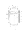
- the heat flux sensor 1 includes a cylindrical main body 2 and a cylinder formed so as to be attached to the outer peripheral surface 8 (outer surface) of the main body 2 of the main body 2.
- a pipe portion 3 having a shape and a plurality of heat sensors 4 having wirings 5 are provided.
- the heat sensor 4 is fixed inside the main body 2, and the wiring 5 extends from the end opposite to the front end surface 7 of the heat flux sensor 1.
- the main body 2 has an axial length that is substantially the same as the thickness of the flying object shroud 51 that is a measurement object, and the front end surface 7 that is the end face in the first direction in the axial direction is a hole in the flying object shroud 51.
- the heat flux sensor 1 is attached so that there is no step between the front end surface 7 of the heat flux sensor 1 and the flying object shroud 51 at the attachment location.
- the axial length of the pipe portion 3 is substantially the same as the thickness of the flying object shroud 51 that is the object to be measured, and the outer peripheral surface 8 of the main body portion of the main body portion 2 and the inner peripheral surface of the pipe portion 3.
- the dimension is such that a predetermined gap is formed between the two.
- the outer peripheral surface of the pipe portion 3 forms the outer peripheral surface 6 of the heat flux sensor 1.
- the main-body part 2 and the pipe part 3 are formed with the same material as the flying body shroud 51, for example, stainless steel.
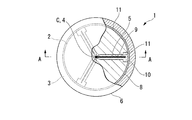
- each perforation 9 is formed from the main body outer peripheral surface 8 of the main body 2 to the central axis C of the main body 2 and is formed at equal intervals when viewed from the axial direction. Specifically, the perforation 9 is formed so that the tip thereof is disposed on the central axis C of the main body 2. In other words, the tip of each perforation 9 is arranged on the same normal line of the front end face 7.
- a thermal sensor 4 described later is disposed at the tip of the perforation 9 so as to contact the tip.
- the distance from the front end surface 7 of the heat sensor 4 is an optimum position for measuring the heat flux, for example, the vicinity of the front end surface 7.
- the axial position of each perforation 9 is the position of the heat sensor 4. It corresponds to.
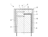
- a plurality of grooves 10 for embedding the wiring 5 of each thermal sensor 4 is formed on the outer peripheral surface 8 of the main body 2 of the main body 2.
- the groove 10 extends from the outer peripheral side end of the perforation 9 in the second direction opposite to the first axial direction (on the opposite side to the front end surface 7).
- the thermal sensor 4 is a sheathed thermocouple that forms a wiring 5 by enclosing a thermocouple element inside a metal protective tube (sheath).
- the thermal sensor 4 is attached so that the hot junction contacts the tip of the perforation 9. That is, the hot junction that is the tip of the thermal sensor 4 is arranged on the central axis C of the main body 2 by arranging the tip of the perforation 9 on the central axis of the main body 2 of the heat flux sensor 1.
- the wiring 5 is extended so as to extend from the second direction side in the axial direction of the main body 2 via the perforations 9 and the grooves 10, and is connected to a predetermined measuring device.
- the perforations 9 are filled with nickel wax 11 as a filler.
- the nickel wax 11 fills the perforations 9 so that gaps are not generated as much as possible. That is, the wiring 5 of the thermal sensor 4 laid in the perforation 9 is sealed with the nickel wax 11.
- the wiring 5 arranged in the groove 10 is also fixed by nickel wax 11.
- the nickel wax 11 applied to the groove 10 also fills the groove 10 so that a gap is not generated as much as possible.
- the nickel wax 11 accumulated in the groove 10 is processed so as to be flush with the main body part outer peripheral surface 8 of the main body part 2. That is, there is no step between the main body outer peripheral surface 8 of the main body 2 and the filler made of nickel wax 11, and it is formed in a flat state.
- the pipe portion 3 is arranged so as to cover the main body portion 2 in a state where the heat sensor 4 is wired and fixed by the nickel wax 11. A predetermined gap between the main body portion 2 and the pipe portion 3 is filled with nickel wax 11. An oxide film 12 is formed on the front end surface 7 of the heat flux sensor 1 and the surface of the pipe portion 3 on the first direction side in the axial direction.
- the heat flux sensor 1 configured as described above is attached to a hole 52 formed at a desired measurement location in the flying object shroud 51. At that time, a filler made of nickel wax 11 is filled between the heat flux sensor 1 and the hole 52.
- a wax material made of nickel is used as a filler to be filled in various places, but the filler is not limited to this, and an error due to a gap (gap) is minimized, and Any material suitable for filling work may be used.
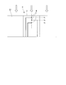
- the temperature set point that is, the distance x from the front end surface 7 of the thermal sensor 4 is defined as x1, x2, and x3, respectively.
- the heat flux q calculated by the process as described above can be calculated by a calculation device (computer) mounted on a measuring device connected to the heat flux sensor 1.
- the manufacturing method of the heat flux sensor 1 of this embodiment is demonstrated.
- the basic dimensions of the heat flux sensor 1 are set.
- the axial length of the heat flux sensor 1 having a cylindrical shape is set so as to be the same as the surface thickness of the flying object shroud 51 which is the measurement target part.
- the diameter of the main body 2 of the heat flux sensor 1 and the pipe thickness of the pipe 3 are set.
- a hole 52 that is slightly larger than the diameter of the cylindrical heat flux sensor 1 is formed in the flying object shroud 51 that is the measurement target part.
- the hole 52 is formed so that the central axis of the hole 52 is orthogonal to the surface of the flying object shroud 51.
- perforations 9 and grooves 10 are formed in the main body 2.
- the perforations 9 are formed by drilling from the outer peripheral surface 8 of the main body 2 in the direction perpendicular to the central axis C of the main body 2 using, for example, a drill.
- three perforations 9 are formed corresponding to the three thermal sensors 4.
- the circumferential positions of the perforations 9 are formed at equal intervals in the circumferential direction. That is, when three perforations 9 are formed, the interval is 180 °.
- the perforation 9 is formed so that the tip thereof coincides with the central axis C of the main body 2.
- the groove 10 is formed by performing processing, for example, using a milling machine from the outer peripheral side end of the perforation 9 toward the second axial side of the main body 2 of the heat flux sensor 1.
- the thermal sensor 4 is inserted into the hole 9. At this time, the insertion is performed until the thermal sensor 4 comes into contact with the tip of the perforation 9.
- the perforation 9 is filled and sealed with nickel wax 11 in a state where the thermal sensor 4 is in contact with the tip of the perforation 9. At this time, the nickel wax 11 is filled so that no voids are formed inside the perforations 9.
- the wiring 5 exposed from the outer peripheral side end portion of the perforation 9 is placed along the inside of the groove 10, and the wiring 5 is fixed with nickel wax 11. At this time, additional machining is performed so that the nickel wax 11 accumulated in the groove 10 is flush with the outer peripheral surface 8 of the main body 2 of the main body 2. That is, the nickel wax 11 is cut so that the nickel wax 11 accumulated in the groove 10 and the pipe portion 3 do not interfere with each other.
- the pipe part 3 is attached so as to cover the main body part 2 to which the heat sensor 4 is attached, and nickel wax 11 is filled between the main body part 2 and the pipe part 3. Also at this time, the filling is sufficiently performed so that no gap is provided between the main body 2 and the pipe 3.
- an oxide film 12 is formed on the front end surface 7 of the heat flux sensor 1.
- the oxide film 12 is formed by exposing the main body 2 to which the pipe portion 3 is attached to the same conditions as the ambient temperature in which the container 3 is stored.
- the heat flux sensor 1 is inserted into the hole 52 of the flying object shroud 51, and the nickel wax 11 is filled between the outer peripheral surface 6 of the heat flux sensor 1 and the inner peripheral surface of the hole 52.
- the heat sensor 4 is disposed in the perforated hole 9 formed in advance, and the heat sensor 4 is fixed by the filler made of nickel wax 11, so that the heat flux error due to the displacement of the thermometer side position. Can be prevented. Further, since the position of the thermal sensor 4 can be determined by the depth of the perforations 9, the thermal sensor 4 can be easily positioned. Moreover, since it is the structure which attaches the main-body part 2 to which the some heat sensor 4 was fixed to the hole 52 of a measurement object, arrangement
- the heat flux error can be reduced by calculating the heat flux from three or more temperatures.
- the nickel wax 11 is filled between the outer peripheral surface 6 of the heat flux sensor 1 and the inner peripheral surface of the hole 52, the temperature difference between the main body 2 and the measurement object becomes smaller. Heat flux error can be reduced.
- the perforations 9 of the main body 2 are provided at equal intervals in the circumferential direction of the main body 2, so that the circumferential balance in the internal structure of the main body 2 is improved, so that the heat flux error is further reduced. be able to. Further, by providing the pipe portion 3 so as to cover the main body portion outer peripheral surface 8 of the main body portion 2, the groove 10 for the wiring 5 formed on the main body portion outer peripheral surface 8 of the main body portion 2 is formed by the pipe portion 3. Since it is covered, it becomes easy to attach the main body 2 to the measurement object.
- the material of the main body 2 and the pipe part 3 is made the same as that of the measurement object, it is possible to further reduce the influence of errors due to heat conduction between the measurement object and the main body part 2 and the pipe part 3.
- the oxide film 12 is formed on the front end surface 7 of the heat flux sensor 1, the state of the front end surface 7 becomes the same as the surface of the object to be measured, so that the error of the heat flux is reduced. Can do.
- the technical scope of the present invention is not limited to the above-described embodiments, and includes those in which various modifications are made to the above-described embodiments without departing from the spirit of the present invention.
- the configuration described in the above-described embodiment is an example, and can be appropriately changed.
- the perforation 9 is formed from the outer peripheral surface 8 of the main body 2 of the main body 2, but the perforation 9 may be formed from other than the front end surface 7 of the main body 2.
- the structure formed from the end surface opposite to the end surface 7 can also be adopted.
- the present invention is not limited to this, and the circumferential intervals of the perforations 9 are not uniform or the same positions as viewed from the axial direction. You may form in.
- the number of thermal sensors 4 is not limited to three, and may be two or four or more. When the number is four or more, the accuracy of the temperature calculation formula at the thermometer side point is improved, which is more preferable.
- the groove 10 was formed in the main body, you may form a groove on the pipe part 3 side.
- the heat flux sensor 1 has a cylindrical shape for ease of manufacturing, but a polygonal shape or the like may be employed. Furthermore, you may comprise the heat flux sensor 1 only by the main-body part 2 without using the pipe part 3. FIG.
- the present invention can be applied to a heat flux sensor attached to a hole formed on the surface of an object to be measured, and can prevent the occurrence of a heat flux error due to a shift of the thermometer side position.
Landscapes
- Chemical & Material Sciences (AREA)
- Engineering & Computer Science (AREA)
- Combustion & Propulsion (AREA)
- Physics & Mathematics (AREA)
- General Physics & Mathematics (AREA)
- Measuring Temperature Or Quantity Of Heat (AREA)
- Investigating Or Analyzing Materials Using Thermal Means (AREA)
Priority Applications (1)
| Application Number | Priority Date | Filing Date | Title |
|---|---|---|---|
| US14/443,162 US9909936B2 (en) | 2012-12-27 | 2013-12-25 | Heat flux sensor and method for manufacturing same |
Applications Claiming Priority (2)
| Application Number | Priority Date | Filing Date | Title |
|---|---|---|---|
| JP2012-285917 | 2012-12-27 | ||
| JP2012285917A JP5931715B2 (ja) | 2012-12-27 | 2012-12-27 | 熱流束センサ及び熱流束センサの製造方法 |
Publications (1)
| Publication Number | Publication Date |
|---|---|
| WO2014104077A1 true WO2014104077A1 (ja) | 2014-07-03 |
Family
ID=51021155
Family Applications (1)
| Application Number | Title | Priority Date | Filing Date |
|---|---|---|---|
| PCT/JP2013/084624 Ceased WO2014104077A1 (ja) | 2012-12-27 | 2013-12-25 | 熱流束センサ及び熱流束センサの製造方法 |
Country Status (3)
| Country | Link |
|---|---|
| US (1) | US9909936B2 (enExample) |
| JP (1) | JP5931715B2 (enExample) |
| WO (1) | WO2014104077A1 (enExample) |
Cited By (2)
| Publication number | Priority date | Publication date | Assignee | Title |
|---|---|---|---|---|
| CN110082006A (zh) * | 2019-05-23 | 2019-08-02 | 江西联创光电科技股份有限公司 | 一种导体棒料内部温度的均匀采样测量方法和设备 |
| CN110082005A (zh) * | 2019-05-23 | 2019-08-02 | 江西联创光电科技股份有限公司 | 一种导体棒料内部温度的非均匀采样测量方法和设备 |
Families Citing this family (3)
| Publication number | Priority date | Publication date | Assignee | Title |
|---|---|---|---|---|
| US10976204B2 (en) * | 2018-03-07 | 2021-04-13 | Rosemount Inc. | Heat flux sensor with improved heat transfer |
| DE102019206013A1 (de) * | 2019-04-26 | 2020-10-29 | Fraunhofer-Gesellschaft zur Förderung der angewandten Forschung e.V. | Grenzschichtsensor, dessen Herstellung und Verwendung |
| FR3132765B1 (fr) | 2022-02-17 | 2024-04-26 | Office National Detudes Rech Aerospatiales | Capteurs pour systèmes de mesure de flux thermique à inertie |
Citations (6)
| Publication number | Priority date | Publication date | Assignee | Title |
|---|---|---|---|---|
| JPS4974274U (enExample) * | 1972-10-11 | 1974-06-27 | ||
| JPS63105853U (enExample) * | 1986-12-27 | 1988-07-08 | ||
| JPH02133640U (enExample) * | 1989-04-13 | 1990-11-06 | ||
| JPH05164626A (ja) * | 1991-12-11 | 1993-06-29 | Kawasaki Steel Corp | 熱電対を用いた温度測定方法 |
| JPH07146189A (ja) * | 1993-11-24 | 1995-06-06 | Mitsubishi Heavy Ind Ltd | 表面熱流束計測装置 |
| JP2003130737A (ja) * | 2001-10-29 | 2003-05-08 | Sukegawa Electric Co Ltd | 熱流束計 |
Family Cites Families (19)
| Publication number | Priority date | Publication date | Assignee | Title |
|---|---|---|---|---|
| US3267726A (en) * | 1961-09-14 | 1966-08-23 | North American Aviation Inc | Heat flux probe |
| JPS537463B2 (enExample) | 1972-11-17 | 1978-03-17 | ||
| US3996070A (en) * | 1974-11-22 | 1976-12-07 | Nasa | Thermocouple installation |
| JPH0639033B2 (ja) | 1986-10-23 | 1994-05-25 | 東芝機械株式会社 | 自動工具交換装置 |
| US4778538A (en) * | 1987-07-15 | 1988-10-18 | Westinghouse Electric Corp. | Dual temperature sensing device having twin well thermowell for dual resistance temperature detectors |
| US4916715A (en) * | 1988-04-13 | 1990-04-10 | General Electric Company | Method and apparatus for measuring the distribution of heat flux and heat transfer coefficients on the surface of a cooled component used in a high temperature environment |
| US4904091A (en) * | 1988-09-15 | 1990-02-27 | The United States Of America As Represented By The Administrator Of The National Aeronautics And Space Administration | Threaded average temperature thermocouple |
| JPH02133640A (ja) | 1988-11-11 | 1990-05-22 | Nippon Felt Kogyo Kk | 不織布 |
| US5086204A (en) * | 1990-05-31 | 1992-02-04 | The United States Of America As Represented By The Administrator Of The National Aeronautics And Space Administration | Method of producing a plug-type heat flux gauge |
| US5048973A (en) * | 1990-05-31 | 1991-09-17 | United States Of America, As Represented By The Administrator Of The National Aeronautics And Space Administration | Plug-type heat flux gauge |
| FR2716534B1 (fr) * | 1994-02-22 | 1996-05-24 | Univ Nantes | Procédé et dispositif de mesure en régime transitoire de températures et flux surfaciques. |
| US5697706A (en) * | 1995-12-26 | 1997-12-16 | Chrysler Corporation | Multi-point temperature probe |
| US5999081A (en) * | 1996-11-29 | 1999-12-07 | Marchi Associates, Inc. | Shielding unique for filtering RFI and EFI interference signals from the measuring elements |
| JPH10274629A (ja) | 1997-01-29 | 1998-10-13 | Mitsubishi Heavy Ind Ltd | 熱伝達率の計測装置 |
| US6485174B1 (en) * | 2000-10-27 | 2002-11-26 | The Babcock & Wilcox Company | Attachable heat flux measuring device |
| US6550963B2 (en) * | 2001-04-26 | 2003-04-22 | Daily Instruments | Multipoint thermocouple |
| US20040136434A1 (en) * | 2003-01-13 | 2004-07-15 | Langley Lawrence W. | Laminated heat flux indicating device |
| JP4813949B2 (ja) | 2006-03-31 | 2011-11-09 | 株式会社日立国際電気 | 熱電対の固定具および被測温物の温度制御装置 |
| US8147130B2 (en) * | 2008-04-18 | 2012-04-03 | General Electric Company | Heat flux measurement device for estimating fouling thickness |
-
2012
- 2012-12-27 JP JP2012285917A patent/JP5931715B2/ja active Active
-
2013
- 2013-12-25 US US14/443,162 patent/US9909936B2/en active Active
- 2013-12-25 WO PCT/JP2013/084624 patent/WO2014104077A1/ja not_active Ceased
Patent Citations (6)
| Publication number | Priority date | Publication date | Assignee | Title |
|---|---|---|---|---|
| JPS4974274U (enExample) * | 1972-10-11 | 1974-06-27 | ||
| JPS63105853U (enExample) * | 1986-12-27 | 1988-07-08 | ||
| JPH02133640U (enExample) * | 1989-04-13 | 1990-11-06 | ||
| JPH05164626A (ja) * | 1991-12-11 | 1993-06-29 | Kawasaki Steel Corp | 熱電対を用いた温度測定方法 |
| JPH07146189A (ja) * | 1993-11-24 | 1995-06-06 | Mitsubishi Heavy Ind Ltd | 表面熱流束計測装置 |
| JP2003130737A (ja) * | 2001-10-29 | 2003-05-08 | Sukegawa Electric Co Ltd | 熱流束計 |
Cited By (2)
| Publication number | Priority date | Publication date | Assignee | Title |
|---|---|---|---|---|
| CN110082006A (zh) * | 2019-05-23 | 2019-08-02 | 江西联创光电科技股份有限公司 | 一种导体棒料内部温度的均匀采样测量方法和设备 |
| CN110082005A (zh) * | 2019-05-23 | 2019-08-02 | 江西联创光电科技股份有限公司 | 一种导体棒料内部温度的非均匀采样测量方法和设备 |
Also Published As
| Publication number | Publication date |
|---|---|
| JP2014126545A (ja) | 2014-07-07 |
| US20150292961A1 (en) | 2015-10-15 |
| JP5931715B2 (ja) | 2016-06-08 |
| US9909936B2 (en) | 2018-03-06 |
Similar Documents
| Publication | Publication Date | Title |
|---|---|---|
| JP5931715B2 (ja) | 熱流束センサ及び熱流束センサの製造方法 | |
| US9243963B2 (en) | Total temperature probe | |
| JP4751492B2 (ja) | 熱電対 | |
| US20170205294A1 (en) | Temperature sensor | |
| ITUB20150948A1 (it) | Elemento di fissaggio, uso di un sensore integrato nell'elemento di fissaggio e metodo per rilevare un flusso termico all'interno di organi meccanici | |
| CN106840268B (zh) | 一种集成总温测量的五孔探针 | |
| TW201629399A (zh) | 鍋爐 | |
| Singh et al. | Error in temperature measurements due to conduction along the sensor leads | |
| JP2014126545A5 (enExample) | ||
| US12092502B2 (en) | Non-invasive thermometer | |
| JP5366772B2 (ja) | 温度検出装置 | |
| JP2012207932A (ja) | 温度分布測定センサ | |
| Brewer | Effect of thermocouple wire size and configuration on internal temperature measurements in a charring Ablator | |
| JP7331726B2 (ja) | 工具摩耗量予測方法及び工具摩耗量予測システム | |
| CN105157873B (zh) | 圆环式光纤光栅温度传感器及封装方法 | |
| JP6804439B2 (ja) | 迅速応答センサ筐体 | |
| KR101831682B1 (ko) | 기체 온도 측정 장치 및 방법 | |
| JP3782958B2 (ja) | 熱流束計 | |
| CN206876305U (zh) | 一种可实现不同插深的热电偶 | |
| CN205484146U (zh) | 用于测量物品热物性的测量装置 | |
| JPS6145463Y2 (enExample) | ||
| JPH088429Y2 (ja) | 温度分布検知センサ | |
| JP2015075460A (ja) | 状態量の検出装置及び検出方法 | |
| KR200301353Y1 (ko) | 스킨패드형 열전대 조립체 | |
| RU69238U1 (ru) | Термоэлектрический преобразователь |
Legal Events
| Date | Code | Title | Description |
|---|---|---|---|
| 121 | Ep: the epo has been informed by wipo that ep was designated in this application |
Ref document number: 13866896 Country of ref document: EP Kind code of ref document: A1 |
|
| WWE | Wipo information: entry into national phase |
Ref document number: 14443162 Country of ref document: US |
|
| NENP | Non-entry into the national phase |
Ref country code: DE |
|
| 122 | Ep: pct application non-entry in european phase |
Ref document number: 13866896 Country of ref document: EP Kind code of ref document: A1 |