WO2014103649A1 - 調圧装置及び燃料電池システム - Google Patents
調圧装置及び燃料電池システム Download PDFInfo
- Publication number
- WO2014103649A1 WO2014103649A1 PCT/JP2013/082676 JP2013082676W WO2014103649A1 WO 2014103649 A1 WO2014103649 A1 WO 2014103649A1 JP 2013082676 W JP2013082676 W JP 2013082676W WO 2014103649 A1 WO2014103649 A1 WO 2014103649A1
- Authority
- WO
- WIPO (PCT)
- Prior art keywords
- valve
- pressure
- pressure reducing
- reducing valve
- valve body
- Prior art date
- Legal status (The legal status is an assumption and is not a legal conclusion. Google has not performed a legal analysis and makes no representation as to the accuracy of the status listed.)
- Ceased
Links
Images

Classifications
-
- G—PHYSICS
- G05—CONTROLLING; REGULATING
- G05D—SYSTEMS FOR CONTROLLING OR REGULATING NON-ELECTRIC VARIABLES
- G05D16/00—Control of fluid pressure
- G05D16/04—Control of fluid pressure without auxiliary power
- G05D16/10—Control of fluid pressure without auxiliary power the sensing element being a piston or plunger
-
- G—PHYSICS
- G05—CONTROLLING; REGULATING
- G05D—SYSTEMS FOR CONTROLLING OR REGULATING NON-ELECTRIC VARIABLES
- G05D16/00—Control of fluid pressure
- G05D16/20—Control of fluid pressure characterised by the use of electric means
- G05D16/2006—Control of fluid pressure characterised by the use of electric means with direct action of electric energy on controlling means
- G05D16/2013—Control of fluid pressure characterised by the use of electric means with direct action of electric energy on controlling means using throttling means as controlling means
- G05D16/2022—Control of fluid pressure characterised by the use of electric means with direct action of electric energy on controlling means using throttling means as controlling means actuated by a proportional solenoid
-
- G—PHYSICS
- G05—CONTROLLING; REGULATING
- G05D—SYSTEMS FOR CONTROLLING OR REGULATING NON-ELECTRIC VARIABLES
- G05D16/00—Control of fluid pressure
- G05D16/20—Control of fluid pressure characterised by the use of electric means
- G05D16/2006—Control of fluid pressure characterised by the use of electric means with direct action of electric energy on controlling means
- G05D16/2013—Control of fluid pressure characterised by the use of electric means with direct action of electric energy on controlling means using throttling means as controlling means
- G05D16/2026—Control of fluid pressure characterised by the use of electric means with direct action of electric energy on controlling means using throttling means as controlling means with a plurality of throttling means
- G05D16/2033—Control of fluid pressure characterised by the use of electric means with direct action of electric energy on controlling means using throttling means as controlling means with a plurality of throttling means the plurality of throttling means being arranged in series
-
- H—ELECTRICITY
- H01—ELECTRIC ELEMENTS
- H01M—PROCESSES OR MEANS, e.g. BATTERIES, FOR THE DIRECT CONVERSION OF CHEMICAL ENERGY INTO ELECTRICAL ENERGY
- H01M8/00—Fuel cells; Manufacture thereof
- H01M8/04—Auxiliary arrangements, e.g. for control of pressure or for circulation of fluids
- H01M8/04082—Arrangements for control of reactant parameters, e.g. pressure or concentration
- H01M8/04201—Reactant storage and supply, e.g. means for feeding, pipes
-
- Y—GENERAL TAGGING OF NEW TECHNOLOGICAL DEVELOPMENTS; GENERAL TAGGING OF CROSS-SECTIONAL TECHNOLOGIES SPANNING OVER SEVERAL SECTIONS OF THE IPC; TECHNICAL SUBJECTS COVERED BY FORMER USPC CROSS-REFERENCE ART COLLECTIONS [XRACs] AND DIGESTS
- Y02—TECHNOLOGIES OR APPLICATIONS FOR MITIGATION OR ADAPTATION AGAINST CLIMATE CHANGE
- Y02E—REDUCTION OF GREENHOUSE GAS [GHG] EMISSIONS, RELATED TO ENERGY GENERATION, TRANSMISSION OR DISTRIBUTION
- Y02E60/00—Enabling technologies; Technologies with a potential or indirect contribution to GHG emissions mitigation
- Y02E60/30—Hydrogen technology
- Y02E60/50—Fuel cells
Definitions
- the present invention relates to a pressure regulator and a fuel cell system.
- JP2006-156320A discloses, as a conventional pressure regulating device, one in which the pressure of anode gas supplied to a fuel cell stack is stepwise reduced using a plurality of pressure reducing valves.
- the pressure reducing valve is depressurized by arranging a plurality of pressure reducing valves in order, so the number of parts such as piping connecting the pressure reducing valves increases, which leads to downsizing There was a problem that it was difficult to plan.
- the present invention has been made in view of such problems, and it is an object of the present invention to miniaturize a pressure regulator that reduces the pressure of fluid.
- a pressure regulator including a first pressure reducing valve that reduces the pressure of the fluid to a predetermined pressure, and a second pressure reducing valve that reduces the pressure of the fluid reduced by the first pressure reducing valve to any pressure.
- the first pressure reducing valve of the pressure regulating device includes a primary passage formed in the axial direction of the first pressure reducing valve and a secondary passage formed in the radial direction of the first pressure reducing valve.
- the second pressure reducing valve is disposed so that the axial direction of the second pressure reducing valve is parallel to the axial direction of the first pressure reducing valve, and the second pressure reducing valve is formed in the radial direction of the second pressure reducing valve.
- a primary passage
- FIG. 1 is a schematic view of a fuel cell system according to an embodiment of the present invention.
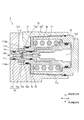
- FIG. 2 is a cross-sectional view of a first pressure reducing valve according to an embodiment of the present invention.
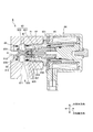
- FIG. 3 is a cross-sectional view of a shutoff valve according to an embodiment of the present invention.
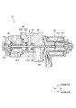
- FIG. 4 is a cross-sectional view of a second pressure reducing valve according to an embodiment of the present invention.
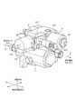
- FIG. 5 is a perspective view of a pressure control apparatus according to an embodiment of the present invention.
- a fuel cell has an electrolyte membrane sandwiched between an anode electrode (fuel electrode) and a cathode electrode (oxidizer electrode), an anode gas (fuel gas) containing hydrogen at the anode electrode, and a cathode gas (oxidant) containing oxygen at the cathode electrode.
- fuel electrode anode electrode
- cathode electrode oxidizer electrode
- anode gas fuel gas
- oxidant cathode gas
- the fuel cell generates an electromotive force of about 1 volt by the electrode reaction of (1) and (2).
- a fuel cell stack in which several hundred fuel cells are stacked is used. Then, a fuel cell system for supplying the anode gas and the cathode gas to the fuel cell stack is configured to extract power for driving the vehicle.
- FIG. 1 is a schematic view of a fuel cell system 100 according to an embodiment of the present invention.
- the fuel cell system 100 includes a fuel cell stack 1, an anode gas supply device 2, and a controller 10.
- the fuel cell stack 1 is formed by stacking hundreds of fuel cells, and receives supply of anode gas and cathode gas to generate electric power necessary for driving the vehicle.
- the cathode gas supply / discharge device for supplying the cathode gas to the fuel cell stack 1 and the cooling device for cooling the fuel cell stack 1 are not the main parts of the present invention, and are not shown for easy understanding. .
- air is used as the cathode gas.
- the anode gas supply device 2 supplies the anode gas to the fuel cell stack 1 and includes a high pressure tank 3, an anode gas supply passage 4, a pressure control device 5, and a pressure sensor 6.
- the high pressure tank 3 maintains the anode gas supplied to the fuel cell stack 1 in a high pressure state and stores it.
- the outlet of the high pressure tank 3 is provided with an open / close valve 31 which is opened when the anode gas is supplied and closed when it is stopped.
- the anode gas supply passage 4 is a passage for supplying the fuel cell stack 1 with the anode gas discharged from the high pressure tank 3. One end of the anode gas supply passage 4 is connected to the high pressure tank 3, and the other end is connected to the anode gas inlet hole of the fuel cell stack 1.
- the pressure control device 5 is a device for reducing the pressure of the anode gas discharged from the high pressure tank 3 to a desired pressure, and is an integrated unit of the first pressure reducing valve 7, the shutoff valve 8 and the second pressure reducing valve 9. is there. Details of the pressure regulator 5 will be described later with reference to FIGS. 2 to 5.
- the first pressure reducing valve 7 reduces the pressure of the anode gas discharged from the high pressure tank 3 to a predetermined pressure.
- the shutoff valve 8 is closed when, for example, the second pressure reducing valve 9 breaks down and the pressure of the anode gas supplied to the fuel cell stack becomes too high when the detection value of the pressure sensor 6 shows an abnormal value. To stop the supply of the anode gas. This prevents high pressure anode gas from being supplied to the fuel cell stack.
- the second pressure reducing valve 9 reduces the pressure of the anode gas reduced to a predetermined pressure by the first pressure reducing valve 7 to a desired pressure according to the operating state of the fuel cell system 100.
- the pressure sensor 6 detects the pressure in the anode gas supply passage 4 downstream of the pressure regulator 5.
- the controller 10 is constituted by a microcomputer provided with a central processing unit (CPU), a read only memory (ROM), a random access memory (RAM) and an input / output interface (I / O interface).
- the controller 10 receives signals from various sensors for detecting the operating state of the fuel cell system 100, such as the current sensor 11 for detecting the output current (load) of the fuel cell stack 1. Be done.
- the controller 10 sets the target pressure of the anode gas according to the operating state of the fuel cell system 100, and performs feedback control of the second pressure reducing valve 9 so that the detected value of the pressure sensor 6 becomes the target pressure. Then, when the detection value of the pressure sensor 6 shows an abnormal value, for example, when the second pressure reducing valve 9 breaks down and the detection value of the pressure sensor 6 becomes too high, the shutoff valve 8 is closed.
- the fuel cell stack 1 in consideration of the weight balance of the vehicle, it is desirable to arrange the fuel cell stack 1 in the space in front of the vehicle and arrange the high pressure tank 3 in the space in the rear of the vehicle. Therefore, although the pressure regulation device 5 is disposed between the fuel cell stack 1 and the high pressure tank 3, the pressure regulation device 5 is formed under the vehicle floor in consideration of the safety at the time of a vehicle rear collision. It is desirable to arrange in the center tunnel with high rigidity. However, in order to arrange the pressure regulator 5 in the center tunnel, it is necessary to make the pressure regulator 5 compact because of the installation space. So, in this embodiment, the 1st pressure-reduction valve 7, the cutoff valve 8, and the 2nd pressure-reduction valve 9 were combined appropriately, and were integrated, and size reduction of pressure regulation device 5 was achieved.
- FIG. 2 is a cross-sectional view of the first pressure reducing valve 7.
- the first pressure reducing valve 7 includes a housing 71, a cover 72, a valve body support member 73, a valve seat 74, a valve body 75, a spring 76, and a bearing 77.
- the housing 71 is a cylindrical member whose one end is open.
- a primary passage 711 which penetrates the inside of the housing in the axial direction of the valve (in the left and right direction in the drawing) and opens at the other end surface of the housing 71, and in the radial direction of the valve
- a secondary passage 712 which penetrates and opens on the side surface of the housing 71 and a communication passage 713 communicating with each of the primary passage 711 and the secondary passage 712 are formed.
- the cover 72 is a lid member closing an opening at one end of the housing, and is screwed to the inner peripheral side of the housing side wall 71 a and fixed to the housing 71.
- the inside of the cover 72 is a housing portion for housing the valve body 75, the spring 76, and the like.
- the valve body support member 73 is a cylindrical member having both ends open, and is provided with a flange 731 projecting in the radial direction of the valve body at a substantially central portion.
- One end side (left side in the drawing) of the valve body support member 73 is fitted to the communication passage 713 such that one end surface of the flange 731 abuts on the housing 71.
- the other end side of the valve body support member 73 is disposed in the housing portion.
- the valve seat 74 is a cylindrical member having open ends, and includes a small diameter portion 741 and a large diameter portion 742.
- the small diameter portion 741 of the valve seat 74 is fitted to the primary passage 711 of the housing 71.
- the large diameter portion 742 of the valve seat 74 is disposed in the communication passage 713 of the housing 71, and the tip thereof is fitted in an annular groove 732 formed in one end surface of the valve body support member 73.
- the large diameter portion 742 of the valve seat 74 is formed with a through hole 743 penetrating the large diameter portion 742 in the valve body radial direction.
- An annular projection (hereinafter referred to as “annular projection”) 744 is formed on the inner boundary surface between the small diameter portion 741 and the large diameter portion 742 from the boundary surface in the axial direction of the valve body.
- the valve body 75 has a cylindrical valve body 751 which is open at both ends and whose diameter changes stepwise along the axial direction of the valve body, and a valve body sheet 752 which is fitted to the tip of the valve body 751. And.
- the valve body 751 is inserted into the inside of the valve support member 73 and supported movably in the axial direction of the valve by a bearing 77 fixed to the inner peripheral portion of the side wall of the valve support member 73.
- the valve body 751 is pressed in the valve opening direction (right side in the drawing) by a spring 76 disposed in the housing portion inside the cover.
- the inside of the valve body 751 is a pressure reference chamber 753 where a secondary pressure acts, and when the secondary pressure becomes larger than the biasing force of the spring 76, the valve body 751 resists the biasing force of the spring 76. Move in the valve closing direction (left side in the figure).
- the valve body sheet 752 is disposed in the communication passage 713 so as to face the annular projection 744 of the valve seat 74, and an orifice 78 is formed between the valve body sheet 752 and the annular projection 744. It has become.
- the communication passage 713 is divided into a primary pressure chamber 713a and a secondary pressure chamber 713b through the orifice 78.
- An introduction hole 754 for introducing the anode gas flowing into the secondary pressure chamber 713 b into the pressure reference chamber 753 of the valve body 751 is formed in the valve body sheet 752.
- valve sheet 752 moves in the valve closing direction together with the valve body 751, and the valve sheet 752 forms an annular projection 744.
- the orifice 78 is closed upon contact.
- FIG. 3 is a cross-sectional view of the shutoff valve 8.
- the shutoff valve 8 includes a housing 81, a joining member 82, a valve body 83, and a solenoid 84 for driving the valve body 83.
- the housing 81 is a cylindrical member whose one end is open.
- a primary passage 811 which penetrates the inside of the housing in the valve body radial direction (vertical direction in the drawing) and opens at the side of the housing 81, and penetrates the inside of the housing in the axial direction of the valve body (horizontal direction in the drawing)
- a secondary passage 812 opened at the other end surface of the housing 81 and a communication passage 813 communicating with each of the primary passage 811 and the secondary passage 812 are formed.
- the joining member 82 is a cylindrical member having both ends open, and is provided with a flange 821 that protrudes in the radial direction of the valve body substantially at the center.
- the joining member 82 is fixed to the housing 81 by screwing one end side (left side in the drawing) into the side wall inner peripheral portion of the housing 81 and fitting the other end side (right side in the drawing) inside the solenoid 84 Being fixed.
- the housing 81 and the solenoid 84 are disposed to face each other via the flange 821 of the joining member 82.
- the valve body 83 includes a pilot valve body 831 and a main valve body 832 coupled to the pilot valve body 831 with a predetermined amount of play by the pilot pin 833, and is driven by exciting the solenoid 84.
- the main valve body 832 is a cylindrical member open at both ends, and is disposed in the communication passage 813 of the housing 81.
- An annular projection (hereinafter referred to as "first annular projection") 834 is formed on one end surface of the main valve body 832 on the left side in the drawing from the one end surface to the left side in the drawing in the axial direction of the valve body. Be done.
- the inside of the other end side (right side in the drawing) of the main valve body 832 is a pilot valve body accommodation chamber 835 for accommodating a part of the pilot valve body 831.
- the pilot valve body accommodation chamber 835 communicates with the secondary passage 812 via the internal passage 836 of the main valve body 832. Further, the pilot valve body accommodation chamber 835 communicates with the primary passage 811 through a gap 837 between the pilot valve body 831 and the main valve body 832 and a gap 838 between the main valve body 832 and the joining member 82.
- an annular projection hereinafter referred to as the “second The projection 839 is formed.
- the pilot valve body 831 is accommodated inside the joint member 82 so as to be movable in the axial direction of the valve body, and one end side (left side in the drawing) of the pilot valve body 831 is disposed in the pilot valve body accommodating chamber 835 of the main valve body 832.
- the pilot valve body accommodation chamber 835 one end side of the pilot valve body 831 and the other end side of the main valve body 832 are connected by the pilot pin 833 with predetermined play in the valve body axial direction.
- the pilot valve body 831 has a cylindrical shape formed so that the diameter gradually increases from one end side (left side in the drawing) to the other end side (right side in the drawing)
- the spring 85 is accommodated inside.
- the pilot valve body 831 is pressed in the valve closing direction (left side in the drawing) by the spring 85, and when the solenoid 84 is not excited, the tip of the pilot valve body 831 is the second annular ring of the main valve body 832 It will be in the valve closing state which contact
- the main valve body 832 connected to the pilot valve body 831 via the pilot pin 833 is also in the valve closed state in which the first annular projection 834 is in contact with the valve seat 86 disposed in the communication passage 813.
- the pilot valve body 831 resists the biasing force of the spring 85 and moves in the valve opening direction (right side in the drawing).
- the tip of the pilot valve 831 first separates from the second annular projection 839, and the anode gas supplied from the primary passage 811 into the communication passage 813 forms a gap 838 between the main valve 832 and the joining member 82.
- From the internal passage 836 of the main valve body 832 through the gap 837 between the pilot valve body 831 and the main valve body 832 and the orifice 87 formed between the pilot valve body 831 and the second annular projection 839 The next passage 812 is supplied.
- the pressure in the secondary passage 812 increases, and the pressure acting on the tip end surface of the main valve body 832 increases.
- the main valve body 832 together with the pilot valve body 831 in the valve opening direction.
- the first annular projection 834 of the main valve body 832 moves away from the valve seat 86.
- the anode gas supplied from the primary passage 811 into the communication passage 813 passes through the orifice 88 formed between the first annular projection 834 of the main valve body 832 and the valve seat 86. It is supplied to 812.
- the main valve body 832 can be moved in the valve opening direction.
- FIG. 4 is a cross-sectional view of the second pressure reducing valve 9.
- the second pressure reducing valve 9 includes a housing 91, a valve body 92, and a solenoid 93 for driving the valve body 92.
- a primary passage 911 extending upward in the valve radial direction (vertical direction in the drawing) inside the housing and opening on the upper side surface of the housing 91 and extending downward in the valve radial direction inside the housing
- a secondary passage 912 extending in the axial direction of the valve body and a communication passage 913 communicating with each of the primary passage 911 and the secondary passage 912 are formed.
- a pressure reference passage 914 branched from the secondary passage 912 and a pressure reference chamber 915 communicating with the pressure reference passage 914 are formed.
- a solenoid is disposed on the opposite side of the pressure reference chamber 915 in the axial direction of the valve body.
- the valve body 92 includes a shaft portion 921 and a taper portion 922, and is disposed in the housing 91 so as to be movable in the valve body axial direction (left and right direction in the drawing).
- valve body 92 In the valve body 92, one end (left side in the figure) of the shaft portion 921 is in contact with the diaphragm 94 disposed in the pressure reference chamber 915, and the diaphragm 92 is formed by the first spring 95 also disposed in the pressure reference chamber 915. It is pressed in the valve closing direction (right direction in the figure) via 94.
- valve body 92 When the solenoid 93 is not excited, the valve body 92 is in a closed state in which the tapered portion 922 is in contact with a valve seat 96 disposed in the communication passage 913. Then, when the solenoid 93 is excited, the plunger rod 932 fixed to the plunger 931 together with the plunger 931 moves in the valve opening direction (left direction in the drawing), and the other end (right side in the drawing) of the shaft portion 921 Press in the valve opening direction. As a result, the valve body 92 also moves in the valve opening direction, and the valve seat 96 is separated from the tapered portion 922 to open the valve.
- a secondary pressure is applied to the pressure reference chamber 915 through the pressure reference passage 914, and a force applied to the diaphragm 94 through the valve body 92 by the excitation generated by the solenoid 93 and the first spring 95
- the valve 92 opens and the primary side Pour gas and keep secondary pressure constant.
- This particular secondary pressure can be made variable according to the amount of energization of the solenoid 93.
- FIG. 5 is a perspective view of a pressure control device 5 in which the first pressure reducing valve 7, the shutoff valve 8 and the second pressure reducing valve 9 are integrated.
- the flow of the anode gas in the pressure control device 5 is indicated by a broken line.
- the anode gas supply passage 4 formed in the longitudinal direction of the vehicle in the center tunnel is parallel to the axial direction of the first pressure reducing valve 7. Be placed. That is, the anode gas supply passage 4 is connected to the primary passage 711 of the first pressure reducing valve 7 so that the anode gas supply passage 4 and the valve axial direction of the first pressure reducing valve 7 are parallel to each other.
- the first pressure reducing valve 7 is disposed such that the secondary passage 712 is parallel to the vehicle width direction.
- the shutoff valve 8 is disposed above the first pressure reducing valve 7 so that the valve body axial direction and the vehicle width direction are parallel.
- the secondary passage 812 of the shutoff valve 8 also becomes parallel to the vehicle width direction.
- the primary passage 811 of the shutoff valve 8 is disposed in parallel with the vertical direction, and the anode gas flowing from the secondary passage 712 of the first pressure reducing valve 7 flows through the primary passage 811 of the shutoff valve 8. It is connected to the secondary passage 712 of the first pressure reducing valve 7 so as to flow vertically from bottom to top.
- the second pressure reducing valve 9 is disposed adjacent to the first pressure reducing valve 7 so that the valve axial direction and the anode gas supply passage 4 formed in the vehicle longitudinal direction are parallel to each other. . That is, the second pressure reducing valve 9 is disposed adjacent to the first pressure reducing valve 7 so that the valve body axial direction and the valve body axial direction of the first pressure reducing valve 7 are parallel to each other. Thus, the secondary passage 912 of the second pressure reducing valve 9 also becomes parallel to the anode gas supply passage 4.
- the primary passage 911 of the second pressure reducing valve 9 is disposed in parallel with the vertical direction, and the anode gas flowing from the secondary passage 812 of the shutoff valve 8 is the primary passage 911 of the second pressure reducing valve 9. Are connected to the secondary passage 812 of the shutoff valve 8 so as to flow vertically from top to bottom.
- the pressure control device 5 reduces the pressure of the anode gas to a predetermined pressure, and the second pressure reduction valve 7 reduces the pressure of the anode gas to an arbitrary pressure.
- a pressure reducing valve 9 The first pressure reducing valve 7 includes a primary passage 711 formed in the axial direction of the first pressure reducing valve 7 and a secondary passage 712 formed in the radial direction of the first pressure reducing valve 7.
- the second pressure reducing valve 9 is disposed such that the valve body axial direction of the second pressure reducing valve 9 is parallel to the valve body axial direction of the first pressure reducing valve 7, and the valve body diameter of the second pressure reducing valve 9 A primary passage 911 formed in the direction is provided.
- the first pressure reducing valve 7 and the second pressure reducing valve 8 which are structurally longest in the axial direction of the valve body, adjacent to each other along the valve body axial direction. it can. And since the secondary passage 712 of the first pressure reducing valve 7 and the primary passage 911 of the second pressure reducing valve 9 are formed in the radial direction of the valve body, the secondary passage 712 of the first pressure reducing valve 7 and the second pressure reducing valve It is possible to minimize the length of the flow path connecting the nine primary passages 911 and to reduce the volume of the entire pressure regulator. Thus, the pressure control device 5 can be miniaturized.
- the primary passage 711 of the first pressure reducing valve 7 is formed in the valve body axial direction, and the secondary passage 712 is formed in the valve body radial direction. Then, the first pressure reducing valve 7 is disposed so that the valve body axial direction is parallel to the anode gas supply passage 4 formed in the longitudinal direction of the vehicle in the center tunnel, and the valve body radial direction is the vehicle width direction It was arranged to be parallel to.
- the primary passage 711 of the first pressure reducing valve 7 is also disposed in parallel with the anode gas supply passage 4, so the primary pressure of the first pressure reducing valve 7 is not curved or the like. It can be directly connected to the passage 711. Therefore, by using the pressure control device 5 according to the present embodiment for the fuel cell system 100, the volume of the entire anode gas supply device can be suppressed, and the piping can be easily managed.
- the second pressure reducing valve 9 is first pressure-reduced so that the axial direction of the valve body is parallel to the anode gas supply passage 4 formed in the longitudinal direction of the vehicle in the center tunnel. It was placed adjacent to the valve 7. Then, the primary passage 911 of the second pressure reducing valve 9 is formed in the valve body radial direction, and the secondary passage 912 is formed in the valve body axial direction.
- the first pressure reducing valve 7 and the second pressure reducing valve 9 both structurally have the longest length in the valve body axial direction, the valve body axial directions of the first pressure reducing valve 7 and the second pressure reducing valve 9 coincide with the vehicle longitudinal direction
- the volume of the entire pressure regulator can be reduced and stored in the center tunnel having a small space, and the space under the vehicle floor can be effectively used. You can also earn ground highs.
- the second pressure reducing valve 9 is configured such that the pressure reference chamber of the second pressure reducing valve 9 is on the vehicle rear side (high pressure tank 3 side) and the second pressure reducing chamber is on the vehicle front side (fuel cell stack 1 side).
- the solenoid 93 of the pressure reducing valve 9 was disposed to come.
- the secondary passage 912 through which the anode gas after pressure reduction structurally flows is formed on the solenoid side of the primary passage 911. Therefore, by arranging the solenoid 93 to come to the front side of the vehicle, it becomes easy to discharge the anode gas of the secondary passage 912 to the front of the vehicle.
- the shutoff valve 8 provided between the first pressure reducing valve 7 and the second pressure reducing valve 9 may be first-operated so that the valve body axial direction and the vehicle width direction are parallel to each other. It was disposed above the pressure reducing valve 7. Then, the primary passage 811 of the shutoff valve 8 is formed in the valve body radial direction so as to be parallel to the vertical direction, and the secondary passage 812 is formed in the valve body axial direction.
- the anode gas flowing parallel to the secondary passage 712 of the first pressure reducing valve 7 flows from the bottom upward in the primary passage 811 of the shut-off valve 8 formed in the vertical direction, and thereafter It can be bent at a right angle and flow toward the primary passage 911 of the second pressure reducing valve 9 in the secondary passage 812 of the shutoff valve 8 parallel to the vehicle width direction.
- the volume increase of the pressure regulator 5 by the shutoff valve 8 provided between the first pressure reducing valve 7 and the second pressure reducing valve 9 is minimized. Can be limited. Therefore, since the pressure control device 5 can be made compact as a whole, it can be stored in a center tunnel with a small space, and the space under the vehicle floor can be used effectively.
- the dust enters the communicating passage 813 of the shutoff valve 8 by gravity even if the anode gas contains dust. You can suppress it. Therefore, dust can be prevented from biting into the pilot valve body 831 and the second annular projection 839 and the like, so that the reliability as the shutoff valve 8 can be improved.
- the first pressure reducing valve 7, the shutoff valve 8 and the second pressure reducing valve 9 are disposed such that the axial direction of each valve body is parallel to the horizontal direction.
- the axial direction of the valve body is arranged parallel to the vertical direction, the end face of each valve body in contact with the valve seat is parallel to the horizontal direction, so if dust adheres to the end face of the valve body, it is difficult to separate Become.
- the axial direction of the valve body is disposed parallel to the horizontal direction, the end face of the valve body is parallel to the vertical direction, and therefore, even if dust adheres to the end face of the valve body, it is easy to detach by gravity. Can.
- the pressure regulating device 5 is provided with the shutoff valve 8 in order to improve the safety of the fuel cell system.
- the shutoff valve 8 is not necessarily required.
- the secondary passage 712 of the first pressure reducing valve 7 and the primary passage 911 of the second pressure reducing valve 9 may be directly connected.
Landscapes
- Physics & Mathematics (AREA)
- Fluid Mechanics (AREA)
- Engineering & Computer Science (AREA)
- General Physics & Mathematics (AREA)
- Automation & Control Theory (AREA)
- Manufacturing & Machinery (AREA)
- Life Sciences & Earth Sciences (AREA)
- Sustainable Development (AREA)
- Sustainable Energy (AREA)
- Chemical & Material Sciences (AREA)
- Chemical Kinetics & Catalysis (AREA)
- Electrochemistry (AREA)
- General Chemical & Material Sciences (AREA)
- Fuel Cell (AREA)
- Control Of Fluid Pressure (AREA)
Abstract
流体の圧力を所定圧力に減圧する第1減圧弁(7)と、第1減圧弁(7)によって減圧された流体を任意の圧力に減圧する第2減圧弁(9)と、を備える調圧装置(5)であって、第1減圧弁(7)は、第1減圧弁(7)の弁体軸方向に形成される1次通路(711)と、第1減圧弁(7)の弁体径方向に形成される2次通路(712)と、を備え、第2減圧弁(9)は、第2減圧弁(9)の弁体軸方向が第1減圧弁(7)の弁体軸方向と平行になるように、第1減圧弁(7)に隣接して配置されると共に、第2減圧弁(9)の弁体径方向に形成される1次通路(911)を備える、ことを特徴とする。
Description
本発明は調圧装置及び燃料電池システムに関する。
JP2006-156320Aには、従来の調圧装置として、燃料電池スタックに供給するアノードガスの圧力を複数の減圧弁を用いて段階的に減圧するものが開示されている。
しかしながら、前述した従来の調圧装置では、複数の減圧弁を順番に配置してアノードガスの圧力を減圧させていたので、減圧弁同士を接続する配管等の部品点数が増加し、小型化を図ることが難しいという問題点があった。
本発明はこのような問題点に着目してなされたものであり、流体の圧力を減圧する調圧装置の小型化を図ることを目的とする。
本発明のある態様によれば、流体の圧力を所定圧力に減圧する第1減圧弁と、第1減圧弁によって減圧された流体を任意の圧力に減圧する第2減圧弁と、を備える調圧装置が提供される。そして、この調圧装置の第1減圧弁は、第1減圧弁の弁体軸方向に形成される1次通路と、第1減圧弁の弁体径方向に形成される2次通路と、を備え、第2減圧弁は、第2減圧弁の弁体軸方向が第1減圧弁の弁体軸方向と平行になるように配置されると共に、第2減圧弁の弁体径方向に形成される1次通路を備える、ことを特徴とする。
以下、図面等を参照して本発明の一実施形態について説明する。
燃料電池は電解質膜をアノード電極(燃料極)とカソード電極(酸化剤極)とによって挟み、アノード電極に水素を含有するアノードガス(燃料ガス)、カソード電極に酸素を含有するカソードガス(酸化剤ガス)を供給することによって発電する。アノード電極及びカソード電極の両電極において進行する電極反応は以下の通りである。
アノード電極 : 2H2 →4H+ +4e- …(1)
カソード電極 : 4H+ +4e- +O2 →2H2O …(2)
カソード電極 : 4H+ +4e- +O2 →2H2O …(2)
この(1)(2)の電極反応によって燃料電池は1ボルト程度の起電力を生じる。
燃料電池を自動車用動力源として使用する場合には、要求される電力が大きいため、数百枚の燃料電池を積層した燃料電池スタックとして使用する。そして、燃料電池スタックにアノードガス及びカソードガスを供給する燃料電池システムを構成して、車両駆動用の電力を取り出す。
図1は、本発明の一実施形態による燃料電池システム100の概略図である。
燃料電池システム100は、燃料電池スタック1と、アノードガス供給装置2と、コントローラ10と、を備える。
燃料電池スタック1は、数百枚の燃料電池を積層したものであり、アノードガス及びカソードガスの供給を受けて、車両の駆動に必要な電力を発電する。なお、燃料電池スタック1にカソードガスを供給するカソードガス給排装置及び燃料電池スタック1を冷却する冷却装置については、本発明の主要部ではないので、理解を容易にするために図示を省略した。本実施形態ではカソードガスとして空気を使用している。
アノードガス供給装置2は、燃料電池スタック1にアノードガスを供給する装置であって、高圧タンク3と、アノードガス供給通路4と、調圧装置5と、圧力センサ6と、を備える。
高圧タンク3は、燃料電池スタック1に供給するアノードガスを高圧状態に保って貯蔵する。高圧タンク3の排出口には、アノードガスを供給するときに開かれ、停止するときに閉じられる開閉弁31が設けられる。
アノードガス供給通路4は、高圧タンク3から排出されるアノードガスを燃料電池スタック1に供給するための通路である。アノードガス供給通路4は、一端が高圧タンク3に接続され、他端が燃料電池スタック1のアノードガス入口孔に接続される。
調圧装置5は、高圧タンク3から排出されたアノードガスの圧力を所望の圧力まで低下させる装置であって、第1減圧弁7、遮断弁8及び第2減圧弁9を一体化したものである。調圧装置5の詳細については、図2から図5を参照して後述する。
第1減圧弁7は、高圧タンク3から排出されたアノードガスの圧力を所定の圧力まで低下させる。
遮断弁8は、圧力センサ6の検出値が異常な値を示したとき、例えば第2減圧弁9が故障して燃料電池スタックに供給されるアノードガスの圧力が高くなりすぎたときに閉じられて、アノードガスの供給を停止させる。これにより、高圧なアノードガスが燃料電池スタックに供給されるのを防止する。
第2減圧弁9は、第1減圧弁7で所定の圧力まで低下させたアノードガスの圧力を、燃料電池システム100の運転状態に応じた所望の圧力まで低下させる。
圧力センサ6は、調圧装置5よりも下流のアノードガス供給通路4の圧力を検出する。
コントローラ10は、中央演算装置(CPU)、読み出し専用メモリ(ROM)、ランダムアクセスメモリ(RAM)及び入出力インタフェース(I/Oインタフェース)を備えたマイクロコンピュータで構成される。コントローラ10には、前述した圧力センサ6のほかにも、燃料電池スタック1の出力電流(負荷)を検出する電流センサ11など、燃料電池システム100の運転状態を検出する各種センサからの信号が入力される。
コントローラ10は、燃料電池システム100の運転状態に応じてアノードガスの目標圧力を設定し、圧力センサ6の検出値が目標圧力となるように第2減圧弁9をフィードバック制御する。そして、圧力センサ6の検出値が異常な値を示したとき、例えば第2減圧弁9が故障して圧力センサ6の検出値が高くなりすぎたときには、遮断弁8を閉じる。
ここで、車両の重量バランスを考慮すると、燃料電池スタック1を車両前方のスペースに配置し、高圧タンク3を車両後方のスペースに配置することが望ましい。そのため、調圧装置5は、燃料電池スタック1と高圧タンク3との間に配置されることになるが、車両後突時の安全性を考慮すると、調圧装置5は、車両床下に形成される剛性の高いセンタートンネル内に配置することが望ましい。しかしながら、調圧装置5をセンタートンネル内に配置しようとすると、設置スペースの関係から調圧装置5をコンパクトにする必要がある。そこで本実施形態では、第1減圧弁7、遮断弁8及び第2減圧弁9を適切に組み合わせて一体化し、調圧装置5の小型化を図った。
以下、第1減圧弁7、遮断弁8及び第2減圧弁9の各構成について説明した後、それらを一体化した調圧装置5について説明する。
図2は、第1減圧弁7の断面図である。
図2に示すように、第1減圧弁7は、ハウジング71と、カバー72と、弁体支持部材73と、弁座74と、弁体75と、スプリング76と、軸受77と、を備える。
ハウジング71は、一端が開口した円筒状の部材である。ハウジング71には、ハウジング内部を弁体軸方向(図中左右方向)に貫通してハウジング71の他端面に開口する1次通路711と、ハウジング内部を弁体径方向(図中上下方向)に貫通してハウジング71の側面に開口する2次通路712と、1次通路711及び2次通路712のそれぞれに連通する連通路713と、が形成される。
カバー72は、ハウジング一端側の開口を閉塞する蓋部材であって、ハウジング側壁71aの内周側に螺合され、ハウジング71に固定される。このカバー72の内側が、弁体75やスプリング76等を収容する収容部となる。
弁体支持部材73は、両端が開口した円筒状の部材であって、略中央部に弁体径方向に突出するフランジ731を備える。弁体支持部材73の一端側(図中左側)は、フランジ731の一端面がハウジング71に当接するように連通路713に嵌合される。弁体支持部材73の他端側は、収容部内に配置される。
弁座74は、両端が開口した円筒状の部材であって、小径部741と大径部742とを備える。弁座74の小径部741は、ハウジング71の1次通路711に嵌合される。弁座74の大径部742は、ハウジング71の連通路713内に配置されると共に、その先端が弁体支持部材73の一端面に形成された環状溝732に嵌合される。弁座74の大径部742には、大径部742を弁体径方向に貫通する貫通孔743が形成される。小径部741と大径部742との内側の境界面には、その境界面から弁体軸方向に突出する円環状の突起(以下「円環突起」という。)744が形成される。
弁体75は、両端が開口し、かつ、弁体軸方向に沿って段階的に径が変化する円筒状の弁体ボディ751と、弁体ボディ751の先端に嵌合する弁体シート752と、を備える。
弁体ボディ751は、弁体支持部材73の内部に挿通され、弁体支持部材73の側壁内周部に固定された軸受77によって弁体軸方向に移動可能に支持される。弁体ボディ751は、カバー内側の収容部内に配置されたスプリング76によって、開弁方向(図中右側)に押圧されている。弁体ボディ751の内部は、2次圧力が作用する圧力参照室753となっており、2次圧力がスプリング76の付勢力よりも大きくなると、弁体ボディ751がスプリング76の付勢力に抗して閉弁方向(図中左側)に移動する。
弁体シート752は、弁座74の円環突起744と対向するように連通路713内に配置されており、弁体シート752と円環突起744との間にはオリフィス78が形成されるようになっている。このオリフィス78を介して、連通路713内が1次圧力室713aと2次圧力室713bとに区画される。弁体シート752の内部には、2次圧力室713bに流入したアノードガスを、弁体ボディ751の圧力参照室753に導入するための導入孔754が形成される。圧力参照室753内の圧力、すなわち2次圧力がスプリング76の付勢力よりも大きくなると、弁体ボディ751と共に弁体シート752が閉弁方向に移動し、弁体シート752が円環突起744に当接してオリフィス78が閉じられる。
図3は、遮断弁8の断面図である。
図3に示すように、遮断弁8は、ハウジング81と、接合部材82と、弁体83と、弁体83を駆動するソレノイド84と、を備える。
ハウジング81は、一端が開口した円筒状の部材である。ハウジング81には、ハウジング内部を弁体径方向(図中上下方向)に貫通してハウジング81の側面に開口する1次通路811と、ハウジング内部を弁体軸方向(図中左右方向)に貫通してハウジング81の他端面に開口する2次通路812と、1次通路811及び2次通路812のそれぞれに連通する連通路813と、が形成される。
接合部材82は、両端が開口した円筒状の部材であって、略中央に弁体径方向に突出するフランジ821を備える。接合部材82は、その一端側(図中左側)がハウジング81の側壁内周部に螺合されてハウジング81に固定されると共に、その他端側(図中右側)がソレノイド84の内部に嵌合されて固定される。これにより、接合部材82のフランジ821を介してハウジング81及びソレノイド84が対向するように配置される。
弁体83は、パイロット弁体831と、パイロットピン833によってパイロット弁体831に所定の遊びをもたせて連結される主弁体832と、を備え、ソレノイド84を励磁することで駆動される。
主弁体832は、両端が開口した円筒状の部材であって、ハウジング81の連通路813内に配置される。図中左側の主弁体832の一端面には、その一端面から図中左側に弁体軸方向に沿って突出する円環状の突起(以下「第1円環突起」という。)834が形成される。
主弁体832の他端側(図中右側)の内部は、パイロット弁体831の一部を収容するためのパイロット弁体収容室835となっている。パイロット弁体収容室835は、主弁体832の内部通路836を介して2次通路812と連通している。また、パイロット弁体収容室835は、パイロット弁体831と主弁体832との隙間837、及び、主弁体832と接合部材82との隙間838を介して1次通路811と連通している。主弁体832の内部通路836とパイロット弁体収容室835との境界面には、その境界面から図中右側に弁体軸方向に沿って突出する円環状の突起(以下「第2円環突起」という。)839が形成される。
パイロット弁体831は、弁体軸方向に移動可能なように接合部材82の内部に収容され、その一端側(図中左側)が主弁体832のパイロット弁体収容室835に配置される。このパイロット弁体収容室835内において、パイロット弁体831の一端側と、主弁体832の他端側とが、パイロットピン833によって弁体軸方向に所定の遊びをもたせて連結される。
また、パイロット弁体831は、一端側(図中左側)から他端側(図中右側)に向かって段階的に径が大きくなるように形成された円筒形状をしており、他端側の内部には、スプリング85が収容される。パイロット弁体831は、このスプリング85によって閉弁方向(図中左側)に押圧されており、ソレノイド84が励磁されていないときは、パイロット弁体831の先端が主弁体832の第2円環突起839に当接した閉弁状態となる。また、パイロットピン833を介してパイロット弁体831に連結された主弁体832も、第1円環突起834が連通路813内に配置された弁座86に当接した閉弁状態となる。
一方で、ソレノイド84が励磁されると、パイロット弁体831がスプリング85の付勢力に抗して開弁方向(図中右側)に移動する。これにより、まずパイロット弁体831の先端が第2円環突起839から離れ、1次通路811から連通路813内に供給されたアノードガスが、主弁体832と接合部材82との隙間838、パイロット弁体831と主弁体832との隙間837、及び、パイロット弁体831と第2円環突起839との間に形成されるオリフィス87を介して、主弁体832の内部通路836から2次通路812へと供給される。これにより、2次通路812内の圧力が上昇するので、主弁体832の先端面に作用する圧力が増加する。
そして、パイロット弁体831が所定量開弁方向に移動して、パイロットピン833と主弁体832との間に存在する遊びが終了すると、主弁体832がパイロット弁体831と共に開弁方向に移動し、主弁体832の第1円環突起834が弁座86から離れる。これにより、1次通路811から連通路813内に供給されたアノードガスが、主弁体832の第1円環突起834と弁座86との間に形成されるオリフィス88を介して2次通路812に供給される。このとき、前述したように主弁体832の先端面に作用する圧力が増加しているので、主弁体832を開弁方向に移動させることができる。
図4は、第2減圧弁9の断面図である。
図4に示すように、第2減圧弁9は、ハウジング91と、弁体92と、弁体92を駆動するソレノイド93と、備える。
ハウジング91には、ハウジング内部を弁体径方向(図中上下方向)上側に延びてハウジング91の上側面に開口する1次通路911と、ハウジング内部を弁体径方向下側に延びた後、最終的に弁体軸方向に延びる2次通路912と、1次通路911及び2次通路912のそれぞれに連通する連通路913と、が形成される。また、ハウジング91には、2次通路912から分岐する圧力参照通路914と、圧力参照通路914に連通する圧力参照室915と、が形成される。そして、この圧力参照室915の弁体軸方向反対側にソレノイドが配置される。
弁体92は、シャフト部921とテーパ部922とを備え、弁体軸方向(図中左右方向)に移動可能なようにハウジング91内に配置される。
弁体92は、シャフト部921の一端(図中左側)が圧力参照室915内に配置されたダイアフラム94に当接しており、同じく圧力参照室915内に配置された第1スプリング95によって、ダイアフラム94を介して閉弁方向(図中右方向)に押圧されている。
弁体92は、ソレノイド93が励磁されていないときは、テーパ部922が連通路913内に配置された弁座96に当接した閉弁状態となっている。そして、ソレノイド93が励磁されると、プランジャ931と共にそのプランジャ931に固定されたプランジャロッド932が開弁方向(図中左方向)に移動して、シャフト部921の他端(図中右側)を開弁方向に押圧する。これにより、弁体92も開弁方向に移動してテーパ部922から弁座96が離れた開弁状態となる。開弁状態になると、圧力参照通路914を介して圧力参照室915に2次圧力がかかり、ソレノイド93の発生する励磁により弁体92を介してダイアフラム94に加わる力と、第1スプリング95がダイアフラム94に加える力と、圧力参照室915に導入された2次圧力がダイアフラム94に加える力のバランスによって、2次圧力が特定の圧力より低い場合、弁体92が開弁して1次側のガスを流し込み、2次圧力を一定に保つ。この特定の2次圧力はソレノイド93の通電量に応じて可変にすることができる。
図5は、第1減圧弁7、遮断弁8及び第2減圧弁9を一体化した調圧装置5の斜視図である。なお、理解を容易にするために、調圧装置5内におけるアノードガスの流れを破線で示した。
図5に示すように、第1減圧弁7は、センタートンネル内に車両前後方向に形成されるアノードガス供給通路4と、第1減圧弁7の弁体軸方向と、が平行となるように配置される。つまり、アノードガス供給通路4と第1減圧弁7の弁体軸方向とが平行となるように、第1減圧弁7の1次通路711にアノードガス供給通路4が接続される。また、第1減圧弁7は、2次通路712が車幅方向と平行となるように配置される。
次に、遮断弁8は、その弁体軸方向と車幅方向とが平行となるように、第1減圧弁7の上方に配置される。これにより、遮断弁8の2次通路812も、車幅方向と平行となる。そして、遮断弁8の1次通路811は、垂直方向と平行になるように配置され、第1減圧弁7の2次通路712から流れてきたアノードガスが、遮断弁8の1次通路811を垂直方向に下から上へ流れるように、第1減圧弁7の2次通路712に接続される。
最後に、第2減圧弁9は、その弁体軸方向と、車両前後方向に形成されるアノードガス供給通路4と、が平行となるように、第1減圧弁7に隣接させて配置される。つまり、第2減圧弁9は、その弁体軸方向と、第1減圧弁7の弁体軸方向とが平行となるように、第1減圧弁7に隣接させて配置される。これにより、第2減圧弁9の2次通路912も、アノードガス供給通路4と平行となる。そして、第2減圧弁9の1次通路911は、垂直方向と平行になるように配置され、遮断弁8の2次通路812から流れてきたアノードガスが第2減圧弁9の1次通路911を垂直方向に上から下へ流れるように、遮断弁8の2次通路812に接続される。
以上説明した本実施形態による調圧装置5は、アノードガスの圧力を所定圧力に減圧する第1減圧弁7と、第1減圧弁7によって減圧されたアノードガスを任意の圧力に減圧する第2減圧弁9と、を備える。そして、第1減圧弁7は、第1減圧弁7の弁体軸方向に形成される1次通路711と、第1減圧弁7の弁体径方向に形成される2次通路712と、を備え、第2減圧弁9は、第2減圧弁9の弁体軸方向が第1減圧弁7の弁体軸方向と平行になるように配置されると共に、第2減圧弁9の弁体径方向に形成される1次通路911を備える。
このような構成としたので、構造的に弁体軸方向の長さが最長寸法となる第1減圧7弁及び第2減圧弁8を、弁体軸方向に沿って隣接して配置することができる。そして、第1減圧弁7の2次通路712及び第2減圧弁9の1次通路911が弁体径方向に形成されているため、第1減圧弁7の2次通路712と第2減圧弁9の1次通路911とを結ぶ流路長さを最小限に抑えて調圧装置全体の体積を抑えることができる。よって、調圧装置5の小型化を図ることができる。
また、本実施形態によれば、第1減圧弁7の1次通路711を弁体軸方向に形成し、2次通路712を弁体径方向に形成した。そして、第1減圧弁7を、弁体軸方向がセンタートンネル内に車両前後方向に形成されるアノードガス供給通路4に対して平行となるように配置すると共に、弁体径方向が車幅方向と平行となるように配置した。
これにより、第1減圧弁7の1次通路711もアノードガス供給通路4と平行に配置されることになるので、アノードガス供給通路4を湾曲等させずに、第1減圧弁7の1次通路711に直接接続することができる。そのため、本実施形態による調圧装置5を燃料電池システム100に用いることで、アノードガス供給装置全体の体積を抑えることできると共に、配管の取り回しも容易となる。
また、本実施形態によれば、第2減圧弁9を、その弁体軸方向がセンタートンネル内に車両前後方向に形成されるアノードガス供給通路4に対して平行となるように、第1減圧弁7に隣接させて配置した。そして、第2減圧弁9の1次通路911を弁体径方向に形成し、2次通路912を弁体軸方向に形成した。
これにより、第1減圧弁7及び第2減圧弁9は、構造的にいずれも弁体軸方向の長さが最長寸法となるが、それぞれの弁体軸方向を車両前後方向と一致させて隣り合わせることで、調圧装置全体の体積を抑えてスペースの少ないセンタートンネル内に格納することができ、車両床下の空間を有効に利用することができる。また、地上最低高も稼ぐことができる。
また、本実施形態によれば、第2減圧弁9を、車両後方側(高圧タンク3側)に第2減圧弁9の圧力参照室が、車両前方側(燃料電池スタック1側)に第2減圧弁9のソレノイド93がくるように配置した。
第2減圧弁9は、その構造的に減圧後のアノードガスが流れる2次通路912が、1次通路911よりもソレノイド側に形成されることになる。そのため、車両前方側にソレノイド93がくるように配置することで、2次通路912のアノードガスを車両前方に排出することが容易となる。
また、本実施形態によれば、第1減圧弁7と第2減圧弁9との間に設けられる遮断弁8を、その弁体軸方向と車幅方向とが平行となるように、第1減圧弁7の上方に配置した。そして、遮断弁8の1次通路811を垂直方向と平行となるように弁体径方向に形成し、2次通路812を弁体軸方向に形成した。
これにより、第1減圧弁7の2次通路712を車幅方向と平行に流れてきたアノードガスを、垂直方向に形成された遮断弁8の1次通路811内において下から上へ流し、その後直角に曲げて、遮断弁8の2次通路812内において車幅方向と平行に第2減圧弁9の1次通路911に向かって流すことができる。このように、遮断弁8内部のアノードガスの経路を直角にすることで、第1減圧弁7と第2減圧弁9との間に設けられる遮断弁8による調圧装置5の体積増加を最小限に抑えることができる。そのため、調圧装置5を全体としてコンパクトにすることができるので、スペースの少ないセンタートンネル内に格納することができ、車両床下の空間を有効に利用することができる。
さらに、遮断弁8の1次通路811内においてアノードガスを下から上へと流すことで、アノードガス中にダストが含まれていても、重力によってダストが遮断弁8の連通路813内に侵入するのを抑制できる。そのため、ダストがパイロット弁体831と第2円環突起839等に噛み込むのを抑制できるので、遮断弁8としての信頼性を向上させることができる。
また、本実施形態によれば、第1減圧弁7、遮断弁8及び第2減圧弁9を、各弁体軸方向が水平方向と平行となるように配置した。弁体軸方向を垂直方向と平行に配置した場合、弁座に当接する各弁体の端面が水平方向と平行になってしまうため、弁体の端面にダストが付着してしまうと脱離しにくくなる。一方で、弁体軸方向を水平方向と平行に配置した場合、弁体の端面は垂直方向と平行になるため、弁体の端面にダストが付着しても、重力によって脱離させやすくすることができる。
以上、本発明の実施形態について説明したが、上記実施形態は本発明の適用例の一部を示したに過ぎず、本発明の技術的範囲を上記実施形態の具体的構成に限定する趣旨ではない。
上記実施形態では、燃料電池システムの安全性を高めるために、調圧装置5に遮断弁8を設けていたが、調圧機能のみが必要な場合、遮断弁8は必ずしも必要ではない。この場合は、第1減圧弁7の2次通路712と第2減圧弁9の1次通路911を直接接続すれば良い。
本願は、2012年12月27日に日本国特許庁に出願された特願2012-285859号に基づく優先権を主張し、この出願の全ての内容は参照により本明細書に組み込まれる。
Claims (8)
- 流体の圧力を所定圧力に減圧する第1減圧弁と、
前記第1減圧弁によって減圧された流体を任意の圧力に減圧する第2減圧弁と、
を備える調圧装置であって、
前記第1減圧弁は、
前記第1減圧弁の弁体軸方向に形成される1次通路と、前記第1減圧弁の弁体径方向に形成される2次通路と、を備え、
前記第2減圧弁は、
前記第2減圧弁の弁体軸方向が前記第1減圧弁の弁体軸方向と平行になるように配置されると共に、
前記第2減圧弁の弁体径方向に形成される1次通路を備える、
調圧装置。 - 前記第1減圧弁と前記第2減圧弁との間に配置される遮断弁をさらに備え、
前記遮断弁は、
前記遮断弁の弁体軸方向が前記第1減圧弁の弁体径方向と平行になるように配置されると共に、
前記遮断弁の弁体径方向に形成されて前記第1減圧弁の2次通路に接続される1次通路と、前記遮断弁の弁体軸方向に形成されて前記第2減圧弁の1次通路に接続される2次通路と、を備える、
請求項1に記載の調圧装置。 - 前記遮断弁は、前記遮断弁の1次通路が垂直方向と平行になるように、かつ、流体が垂直方向上向きに流れるように配置される、
請求項2に記載の調圧装置。 - 前記第1減圧弁、前記第2減圧弁及び前記遮断弁は、それぞれの弁体軸方向が水平方向と平行となるように配置される、
請求項3又は請求項4に記載の調圧装置。 - 請求項1から請求項4までのいずれか1つに記載された調圧装置を備える燃料電池システムであって、
アノードガスを蓄える高圧タンクと、
前記高圧タンクと燃料電池とを接続するアノードガス供給通路と、
を備え、
前記調圧装置は、前記アノードガス供給通路に設けられて、アノードガスの圧力を減圧する、
燃料電池システム。 - 前記アノードガス供給通路は、前記高圧タンクから前記燃料電池向かって直線的に形成され、
前記第1減圧弁は、前記第1減圧弁の弁体軸方向と前記アノードガス供給通路とが平行になるように配置される、
請求項5に記載の燃料電池システム。 - 前記第2減圧弁は、前記第2減圧弁の2次通路の圧力を参照して弁体を閉弁方向に駆動する圧力参照機構と、前記圧力参照機構の駆動力に抗する力を発生し、前記弁体を開弁方向に駆動するソレノイドと、を備え、
前記高圧タンク側に前記圧力参照機構が配置され、前記燃料電池側に前記ソレノイドが配置される、
請求項5又は請求項6に記載の燃料電池システム。 - 前記第2減圧弁の2次通路は、前記第2減圧弁の1次通路よりも前記ソレノイド側に配置される、
請求項7に記載の燃料電池システム。
Applications Claiming Priority (2)
| Application Number | Priority Date | Filing Date | Title |
|---|---|---|---|
| JP2012-285859 | 2012-12-27 | ||
| JP2012285859A JP2014127176A (ja) | 2012-12-27 | 2012-12-27 | 調圧装置及び燃料電池システム |
Publications (1)
| Publication Number | Publication Date |
|---|---|
| WO2014103649A1 true WO2014103649A1 (ja) | 2014-07-03 |
Family
ID=51020743
Family Applications (1)
| Application Number | Title | Priority Date | Filing Date |
|---|---|---|---|
| PCT/JP2013/082676 Ceased WO2014103649A1 (ja) | 2012-12-27 | 2013-12-05 | 調圧装置及び燃料電池システム |
Country Status (2)
| Country | Link |
|---|---|
| JP (1) | JP2014127176A (ja) |
| WO (1) | WO2014103649A1 (ja) |
Citations (4)
| Publication number | Priority date | Publication date | Assignee | Title |
|---|---|---|---|---|
| JP2005157913A (ja) * | 2003-11-27 | 2005-06-16 | Yutaka:Kk | 圧力調整器 |
| JP2005222378A (ja) * | 2004-02-06 | 2005-08-18 | Keihin Corp | 減圧弁 |
| JP2011519074A (ja) * | 2007-10-03 | 2011-06-30 | ロバート・リュウ・ツーラン、ジュニア | レギュレータ、動力供給システムおよびそれらの使用方法 |
| WO2012017665A1 (ja) * | 2010-08-06 | 2012-02-09 | 川崎重工業株式会社 | 燃料電池システムの水素ガス供給装置 |
-
2012
- 2012-12-27 JP JP2012285859A patent/JP2014127176A/ja active Pending
-
2013
- 2013-12-05 WO PCT/JP2013/082676 patent/WO2014103649A1/ja not_active Ceased
Patent Citations (4)
| Publication number | Priority date | Publication date | Assignee | Title |
|---|---|---|---|---|
| JP2005157913A (ja) * | 2003-11-27 | 2005-06-16 | Yutaka:Kk | 圧力調整器 |
| JP2005222378A (ja) * | 2004-02-06 | 2005-08-18 | Keihin Corp | 減圧弁 |
| JP2011519074A (ja) * | 2007-10-03 | 2011-06-30 | ロバート・リュウ・ツーラン、ジュニア | レギュレータ、動力供給システムおよびそれらの使用方法 |
| WO2012017665A1 (ja) * | 2010-08-06 | 2012-02-09 | 川崎重工業株式会社 | 燃料電池システムの水素ガス供給装置 |
Also Published As
| Publication number | Publication date |
|---|---|
| JP2014127176A (ja) | 2014-07-07 |
Similar Documents
| Publication | Publication Date | Title |
|---|---|---|
| CN103137990B (zh) | 流体供应系统 | |
| JP5041272B2 (ja) | 燃料電池システム及び移動体 | |
| US10170784B2 (en) | Regenerative fuel cell system | |
| JP2018152314A (ja) | 燃料電池システム及びその制御方法 | |
| JP2010001916A (ja) | 電磁遮断弁 | |
| US8820712B2 (en) | Opening and closing valve for high-pressure gas | |
| JP7569945B2 (ja) | 燃料電池システム、ガスタンク装置、およびガスタンク装置のための遮断弁 | |
| US9853316B2 (en) | Fuel cell system | |
| JP6207477B2 (ja) | 燃料供給ユニット | |
| JP6117551B2 (ja) | 調圧装置及び燃料電池システム | |
| JP5161624B2 (ja) | 燃料電池システム | |
| JP6868371B2 (ja) | 高圧流体制御弁および燃料電池システム | |
| JP2008140741A (ja) | 燃料電池システム | |
| JP4367160B2 (ja) | 圧力調整弁 | |
| WO2014103649A1 (ja) | 調圧装置及び燃料電池システム | |
| JP2012189108A (ja) | インジェクタ付きタンク弁と燃料電池システム | |
| JP2012219949A (ja) | 流体供給システム | |
| JP2009168166A (ja) | 高圧タンク用のバルブシステムおよび燃料電池システム | |
| JP2009146855A (ja) | 圧力調整装置 | |
| US20080113252A1 (en) | Fuel Cell System | |
| JP5007931B2 (ja) | 燃料タンクの支持装置 | |
| JP4998695B2 (ja) | 燃料電池システム | |
| JP2006065586A (ja) | 減圧弁 | |
| JP4622319B2 (ja) | 燃料電池システム | |
| JP2005347189A (ja) | 燃料電池システム |
Legal Events
| Date | Code | Title | Description |
|---|---|---|---|
| 121 | Ep: the epo has been informed by wipo that ep was designated in this application |
Ref document number: 13867459 Country of ref document: EP Kind code of ref document: A1 |
|
| NENP | Non-entry into the national phase |
Ref country code: DE |
|
| 122 | Ep: pct application non-entry in european phase |
Ref document number: 13867459 Country of ref document: EP Kind code of ref document: A1 |