WO2014103497A1 - 車載制御装置 - Google Patents
車載制御装置 Download PDFInfo
- Publication number
- WO2014103497A1 WO2014103497A1 PCT/JP2013/079128 JP2013079128W WO2014103497A1 WO 2014103497 A1 WO2014103497 A1 WO 2014103497A1 JP 2013079128 W JP2013079128 W JP 2013079128W WO 2014103497 A1 WO2014103497 A1 WO 2014103497A1
- Authority
- WO
- WIPO (PCT)
- Prior art keywords
- vehicle
- storage battery
- charging
- battery
- ignition
- Prior art date
- Legal status (The legal status is an assumption and is not a legal conclusion. Google has not performed a legal analysis and makes no representation as to the accuracy of the status listed.)
- Ceased
Links
Images



Classifications
-
- B—PERFORMING OPERATIONS; TRANSPORTING
- B60—VEHICLES IN GENERAL
- B60L—PROPULSION OF ELECTRICALLY-PROPELLED VEHICLES; SUPPLYING ELECTRIC POWER FOR AUXILIARY EQUIPMENT OF ELECTRICALLY-PROPELLED VEHICLES; ELECTRODYNAMIC BRAKE SYSTEMS FOR VEHICLES IN GENERAL; MAGNETIC SUSPENSION OR LEVITATION FOR VEHICLES; MONITORING OPERATING VARIABLES OF ELECTRICALLY-PROPELLED VEHICLES; ELECTRIC SAFETY DEVICES FOR ELECTRICALLY-PROPELLED VEHICLES
- B60L58/00—Methods or circuit arrangements for monitoring or controlling batteries or fuel cells, specially adapted for electric vehicles
- B60L58/10—Methods or circuit arrangements for monitoring or controlling batteries or fuel cells, specially adapted for electric vehicles for monitoring or controlling batteries
- B60L58/12—Methods or circuit arrangements for monitoring or controlling batteries or fuel cells, specially adapted for electric vehicles for monitoring or controlling batteries responding to state of charge [SoC]
- B60L58/15—Preventing overcharging
-
- B—PERFORMING OPERATIONS; TRANSPORTING
- B60—VEHICLES IN GENERAL
- B60W—CONJOINT CONTROL OF VEHICLE SUB-UNITS OF DIFFERENT TYPE OR DIFFERENT FUNCTION; CONTROL SYSTEMS SPECIALLY ADAPTED FOR HYBRID VEHICLES; ROAD VEHICLE DRIVE CONTROL SYSTEMS FOR PURPOSES NOT RELATED TO THE CONTROL OF A PARTICULAR SUB-UNIT
- B60W10/00—Conjoint control of vehicle sub-units of different type or different function
-
- G—PHYSICS
- G01—MEASURING; TESTING
- G01R—MEASURING ELECTRIC VARIABLES; MEASURING MAGNETIC VARIABLES
- G01R31/00—Arrangements for testing electric properties; Arrangements for locating electric faults; Arrangements for electrical testing characterised by what is being tested not provided for elsewhere
- G01R31/36—Arrangements for testing, measuring or monitoring the electrical condition of accumulators or electric batteries, e.g. capacity or state of charge [SoC]
- G01R31/382—Arrangements for monitoring battery or accumulator variables, e.g. SoC
-
- H—ELECTRICITY
- H02—GENERATION; CONVERSION OR DISTRIBUTION OF ELECTRIC POWER
- H02J—ELECTRIC POWER NETWORKS; CIRCUIT ARRANGEMENTS OR SYSTEMS FOR SUPPLYING OR DISTRIBUTING ELECTRIC POWER; SYSTEMS FOR STORING ELECTRIC ENERGY
- H02J7/00—Circuit arrangements for charging or discharging batteries or for supplying loads from batteries
-
- Y—GENERAL TAGGING OF NEW TECHNOLOGICAL DEVELOPMENTS; GENERAL TAGGING OF CROSS-SECTIONAL TECHNOLOGIES SPANNING OVER SEVERAL SECTIONS OF THE IPC; TECHNICAL SUBJECTS COVERED BY FORMER USPC CROSS-REFERENCE ART COLLECTIONS [XRACs] AND DIGESTS
- Y02—TECHNOLOGIES OR APPLICATIONS FOR MITIGATION OR ADAPTATION AGAINST CLIMATE CHANGE
- Y02T—CLIMATE CHANGE MITIGATION TECHNOLOGIES RELATED TO TRANSPORTATION
- Y02T10/00—Road transport of goods or passengers
- Y02T10/60—Other road transportation technologies with climate change mitigation effect
- Y02T10/70—Energy storage systems for electromobility, e.g. batteries
-
- Y—GENERAL TAGGING OF NEW TECHNOLOGICAL DEVELOPMENTS; GENERAL TAGGING OF CROSS-SECTIONAL TECHNOLOGIES SPANNING OVER SEVERAL SECTIONS OF THE IPC; TECHNICAL SUBJECTS COVERED BY FORMER USPC CROSS-REFERENCE ART COLLECTIONS [XRACs] AND DIGESTS
- Y02—TECHNOLOGIES OR APPLICATIONS FOR MITIGATION OR ADAPTATION AGAINST CLIMATE CHANGE
- Y02T—CLIMATE CHANGE MITIGATION TECHNOLOGIES RELATED TO TRANSPORTATION
- Y02T90/00—Enabling technologies or technologies with a potential or indirect contribution to GHG emissions mitigation
- Y02T90/10—Technologies relating to charging of electric vehicles
- Y02T90/16—Information or communication technologies improving the operation of electric vehicles
Definitions
- the present invention relates to an in-vehicle control device.
- the number of cases in which the vehicle-mounted lead battery is charged while the vehicle is parked (for example, charging from a plug-in charger or a solar cell), and the OCV while the vehicle is parked is stable. Therefore, it is becoming difficult to accurately measure the state of charge of the battery (SOC measurement) while the vehicle is parked.
- This invention is made in view of said point, and makes it a subject to provide the vehicle-mounted control apparatus which can measure the charge condition of a battery accurately while parking a vehicle.
- the vehicle-mounted control device includes a power generation unit including a communication unit, a storage battery that can be charged by receiving power from the power generation unit, and a control unit configured to be able to communicate with the communication unit and controlling charging of the storage battery. And a charging state measuring means for measuring the charging state of the storage battery, and the control means transmits a signal for prohibiting charging of the storage battery to the communication unit when the ignition of the vehicle is turned off.
- the charge state measuring means is required to measure the state of charge of the storage battery after the ignition of the vehicle is turned off and during the period when charging of the storage battery is prohibited.
- an in-vehicle control device capable of accurately measuring the state of charge of the battery while the vehicle is parked.
- FIG. 1 is a block diagram illustrating an in-vehicle control device according to the first embodiment.
- an in-vehicle control device 10 according to a first embodiment is mounted on a vehicle (not shown).
- a lead battery 20 As main components, a lead battery 20, an ECU 30, a battery sensor 40, and power generation means are provided. 50.
- the lead battery 20 is a storage battery having a function of supplying operating power to a predetermined in-vehicle device (not shown) mounted on the vehicle.
- the lead battery 20 can be charged by generating electric power from an alternator that generates electric power through rotation of an in-vehicle engine and regeneration during deceleration of the vehicle or by receiving electric power from a power generation means 50.
- the lead battery 20 is a typical example of a storage battery according to the present invention.
- the storage battery according to the present invention is not limited to a lead battery, and may be another secondary battery in which polarization occurs by charging.
- the ECU 30 (electronic control unit 30) is configured mainly with a microcomputer, and is a unit that performs charge control of the lead battery 20 and the like.
- the ECU 30 is configured to be communicable (data transmission / reception is possible) with a communication unit 51 of the power generation means 50 and another ECU (electronic control unit) (not shown) mounted on the vehicle by communication such as an electric wire or CAN. Yes.
- the ECU 30 is a typical example of the control means according to the present invention.
- the battery sensor 40 is attached to the negative terminal of the lead battery 20.
- the battery sensor 40 has a built-in microcomputer, and measures the OCV (open circuit voltage) of the lead battery 20 and measures the SOC (charged state of the lead battery 20) based on the measured OCV. is there.
- the battery sensor 40 can bidirectionally transmit and receive signals to and from the ECU 30 according to a predetermined communication protocol such as LIN communication.
- the power generation means 50 is, for example, a solar cell that is mounted on a vehicle roof or the like and generates power using solar energy.
- the power generation means 50 is configured to charge the lead battery 20 via, for example, a DC-DC converter (not shown).
- the power generation means 50 includes a communication unit 51.
- the communication unit 51 includes a microcomputer, and is configured to be communicable with the ECU 30 (data transmission / reception is possible).
- the power generation means 50 is not limited to a solar battery, and may be a battery that generates power using, for example, heat (exhaust heat) energy generated from the vehicle, vibration energy generated from the vehicle, or the like.
- the operation when the vehicle-mounted control device 10 measures the state of charge of the lead battery 20 when the vehicle is parked will be described.
- the ECU 30 transmits a signal (charge prohibition signal) for prohibiting charging of the lead battery 20 to the communication unit 51.
- the communication unit 51 receives the charge prohibition signal, the power generation means 50 stands by without charging the lead battery 20.
- the time when the ignition is turned off is, for example, from when an ignition turn-off command is issued until an ignition relay (not shown) provided on the power supply line is turned off.
- Information on the ignition can be obtained from the power supply ECU or the like via an in-vehicle LAN or the like.
- the timing of transmission and the ignition relay are turned off.
- the delicate context with timing is not a problem. That is, the timing at which the signal prohibiting charging of the lead battery 20 is transmitted may be before the ignition relay (not shown) is turned off, at the same time when it is turned off, or after the off time.
- the battery sensor 40 measures the state of charge (SOC) of the lead battery 20 after the ignition of the vehicle is turned off and during the period when charging of the lead battery 20 is prohibited.
- SOC state of charge
- the battery sensor 40 obtains information on whether or not the ignition of the vehicle is turned off (after the ignition relay is turned off) directly from the power supply ECU or the like via the in-vehicle LAN or via the ECU 30. Can do.
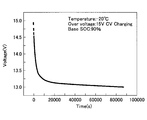
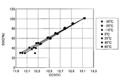
- the SOC is measured using, for example, the relationship shown in FIGS. That is, as shown in FIG. 2, when a sufficient amount of time elapses after the charging of the lead battery is stopped, the polarization is relaxed and the OCV is stabilized, and the SOC and OCV at that time have a correlation as shown in FIG. Therefore, the battery sensor 40 measures the OCV of the lead battery 20 and measures the SOC based on the measured OCV. The measurement result of the SOC is transmitted to the ECU 30.
- the ECU 30 transmits a signal (charging permission signal) for permitting charging of the lead battery 20 to the communication unit 51.
- a signal charging permission signal
- the power generation means 50 starts charging the lead battery 20.
- the battery sensor transmits a signal prohibiting charging of the lead battery to the power generation means.
- the charge state of the lead battery is measured after the ignition of the vehicle is turned off and during the period when charging of the lead battery is prohibited.
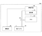
- FIG. 4 is a block diagram illustrating a vehicle-mounted control device according to a modification of the first embodiment.
- in-vehicle control device 10 ⁇ / b> A according to the modification of the first embodiment is that in-vehicle control device 10 according to the first embodiment (see FIG. 1) is that storage battery 60 is added. Is different.
- the storage battery 60 is, for example, a secondary battery capable of charging / discharging such as lithium ion or nickel hydride having a function of supplying operating power to a predetermined in-vehicle device (not shown) mounted on the vehicle as an auxiliary machine of the lead battery 20. It is a battery.
- the storage battery 60 can be charged by generating electric power from an alternator that generates electric power by rotation of an on-vehicle engine and regeneration at the time of deceleration of the vehicle or by receiving electric power from a power generation means 50.
- the power generation means 50 can supply power to the storage battery 60 according to a command from the ECU 30.
- the storage battery 60 is a typical example of the second storage battery according to the present invention.
- the ECU 30 when a plurality of batteries are mounted on the vehicle, the ECU 30 preferably has the following functions in addition to the functions shown in the first embodiment. That is, the ECU 30 preferably has a function of predetermining a time zone (timing) for prohibiting charging of the lead battery 20.
- the ECU 30 can have a function of performing control such as separating a battery to be charged every time the vehicle is parked. Specifically, when the next vehicle is parked, the lead battery 20 is charged from the power generation means 50, and when the next vehicle is parked, charging from the power generation means 50 to the lead battery 20 is prohibited and the storage battery 60 is charged. And the battery sensor 40 measures the charge state of the lead battery 20 in the time slot
- the ECU 30 transmits a signal for prohibiting the charging of the lead battery 20 to the communication unit 51 when the ignition of the vehicle is turned off during the time when the charging of the lead battery 20 is prohibited.
- a signal permitting charging of the storage battery 60 is transmitted, and after the ignition of the vehicle is turned off, the state of charge of the lead battery 20 can be measured while the storage battery 60 is being charged.
- the battery sensor 40 is not charged from the power generation means 50 to the lead battery 20 at the current vehicle parking. Even if the state of charge is measured, problems such as a marked decrease in the charge amount of the lead battery 20 can be avoided.
- the time zone (timing) for prohibiting charging the lead battery is determined in advance, and the lead from the power generation means in that time zone.
- the state where the OCV becomes unstable due to the charging of the battery can be reliably avoided, and the state of charge of the lead battery can be accurately measured while the vehicle is parked (the SOC can be measured).
- FIG. 5 is a block diagram illustrating a vehicle-mounted control device according to the second embodiment.
- an in-vehicle control device 10B according to the second embodiment is mounted on a vehicle (not shown).
- a lead battery 20 As main components, a lead battery 20, an ECU 30, a battery sensor 40, and an air conditioner ECU 70 are provided. And an air conditioner 80, a headlamp relay 90, and a headlamp 100.
- the air conditioner ECU 70 (air conditioner electronic control unit 70) is configured mainly with a microcomputer, and is a unit that controls the air conditioner 80 and the like.
- the air conditioner ECU 70 is connected to the ECU 30 via an in-vehicle LAN such as CAN or directly, and is configured to be able to transmit / receive data to / from the ECU 30.
- the air conditioner 80 is a device that is powered by the lead battery 20 and performs air conditioning in the vehicle, and operates according to a command from the air conditioner ECU 70.
- the headlamp relay 90 is a relay that is turned on / off by a command from the ECU 30.
- the headlamp 100 is a device that receives power from the lead battery 20 and emits light to the outside of the vehicle, and operates when the headlamp relay 90 is turned on by a command from the ECU 30.
- the ECU 30 can eliminate the polarization of the lead battery 20 at an early stage by discharging the lead battery 20 to the high power load in a short period after the ignition of the vehicle is turned off.
- the ECU 30 issues a command to the air conditioner ECU 70 to operate the air conditioner 80 after the ignition of the vehicle is turned off.
- the ECU 30 issues a command to turn on the headlamp relay 90 and activates the headlamp 100.
- the ECU 30 may simultaneously operate the air conditioner 80 and the headlamp 100 after the ignition of the vehicle is turned off.
- the ECU 30 also supplies other loads (for example, heaters and audio devices) (not shown) that are powered by the lead battery 20 to operate after the ignition of the vehicle is turned off, simultaneously with the air conditioner 80 and the headlamp 100, or independently. It may be activated.
- the lead is supplied by the command from the ECU after the ignition of the vehicle is turned off and before the battery sensor starts measuring the state of charge of the lead battery. Discharge from the battery to the high power load for a predetermined time.
- the OCV stabilizes due to the early elimination of the polarization of the lead battery, and the battery sensor then measures the charge state of the lead battery, thereby accurately measuring the charge state of the lead battery in a short time while the vehicle is parked. It becomes possible to do.
- the second embodiment may be applied to the first embodiment.
- a signal prohibiting charging of the lead battery 20 is transmitted from the EUC 30 to the power generation means 50, and after the vehicle ignition is turned off, the battery sensor Before 40 starts measuring the state of charge of the lead battery 20, the high-power load may be discharged for a predetermined time.
- FIG. 6 is a block diagram illustrating a vehicle-mounted control device according to a modification of the second embodiment.
- in-vehicle control device 10 ⁇ / b> C according to the modification of the second embodiment is the in-vehicle control device 10 ⁇ / b> B according to the second embodiment (see FIG. 5) in that a storage battery 60 is added. Is different.
- the storage battery 60 is connected to the lead battery 20 via the relay 110.
- Relay 110 is a relay that is turned on / off by a command from ECU 30.
- the storage battery 60 is configured to be rechargeable from the lead battery 20 when the relay 110 is turned on by a command from the ECU 30.
- the storage battery 60 is charged by converting the voltage from the lead battery 20 into a voltage capable of charging the storage battery 60 by a DC-DC converter (not shown).
- the ECU 30 issues a command to turn on the relay 110 and charges the storage battery 60 from the lead battery 20 to discharge the charge of the lead battery 20.
- the polarization of the lead battery 20 can be eliminated at an early stage.
- the ECU 30 After the ignition of the vehicle is turned off and before the battery sensor starts measuring the charge state of the lead battery, the ECU 30 The storage battery 60 is charged from the lead battery 20 according to the command. As a result, since the OCV is stabilized due to the early elimination of the polarization of the lead battery 20, the battery sensor then measures the state of charge of the lead battery, so that the state of charge of the lead battery can be accurately determined in a short time while the vehicle is parked. It becomes possible to measure.
- the modification of the second embodiment may be applied to the modification of the first embodiment.
- a signal prohibiting charging of the lead battery 20 is transmitted from the EUC 30 to the power generation means 50, and after the vehicle ignition is turned off, the battery sensor Before the battery 40 starts measuring the state of charge of the lead battery 20, the storage battery 60 may be charged from the lead battery 20.
Landscapes
- Engineering & Computer Science (AREA)
- Mechanical Engineering (AREA)
- Transportation (AREA)
- General Physics & Mathematics (AREA)
- Physics & Mathematics (AREA)
- Power Engineering (AREA)
- Chemical & Material Sciences (AREA)
- Combustion & Propulsion (AREA)
- Life Sciences & Earth Sciences (AREA)
- Sustainable Development (AREA)
- Sustainable Energy (AREA)
- Charge And Discharge Circuits For Batteries Or The Like (AREA)
- Secondary Cells (AREA)
Abstract
Description
第1の実施の形態の変形例では、車両に複数のバッテリを搭載している場合の車載制御装置の動作の例を示す。なお、第1の実施の形態の変形例において、既に説明した実施の形態と同一構成部についての説明は省略する。
第2の実施の形態では、鉛バッテリの分極を早期に解消させる例を示す。なお、第2の実施の形態において、既に説明した実施の形態と同一構成部についての説明は省略する。
第2の実施の形態の変形例では、車両に複数のバッテリを搭載している場合の車載制御装置の動作の例を示す。なお、第2の実施の形態の変形例において、既に説明した実施の形態と同一構成部についての説明は省略する。
20 鉛バッテリ
30 ECU
40 バッテリセンサ
50 発電手段
51 通信部
60 蓄電池
70 エアコンECU
80 エアコン
90 ヘッドランプリレー
100 ヘッドランプ
110 リレー
Claims (5)
- 通信部を備えた発電手段と、
前記発電手段から電力を受給することにより充電可能な蓄電池と、
前記通信部と通信可能に構成され、前記蓄電池の充電を制御する制御手段と、
前記蓄電池の充電状態を測定する充電状態測定手段と、を有し、
前記制御手段は、車両のイグニッションがオフされる際に、前記通信部に前記蓄電池への充電を禁止する信号を送信し、
前記充電状態測定手段は、車両のイグニッションがオフされた後であって、前記蓄電池への充電が禁止されている期間中に、前記蓄電池の充電状態を測定する車載制御装置。 - 前記制御手段は、前記蓄電池の充電状態の測定が終了した後、前記通信部に前記蓄電池への充電を許可する信号を送信する請求項1記載の車載制御装置。
- 前記発電手段から電力を受給することにより充電可能な第2の蓄電池を更に有し、
前記制御手段は、前記蓄電池への充電を禁止する時間帯を予め定めておき、
前記充電状態測定手段は、前記時間帯に前記蓄電池の充電状態を測定する請求項1記載の車載制御装置。 - 前記制御手段は、前記時間帯に、車両のイグニッションがオフされる際に、前記通信部に前記蓄電池の充電を禁止する信号を送信すると共に、前記第2の蓄電池の充電を許可する信号を送信し、
前記充電状態測定手段は、車両のイグニッションがオフされた後であって、前記第2の蓄電池への充電中に、前記蓄電池の充電状態を測定する請求項3記載の車載制御装置。 - 前記発電手段は、光、熱、又は振動のエネルギーにより発電する請求項1記載の車載制御装置。
Priority Applications (4)
| Application Number | Priority Date | Filing Date | Title |
|---|---|---|---|
| CN201380067514.2A CN104903153B (zh) | 2012-12-27 | 2013-10-28 | 车载控制装置 |
| JP2014554206A JP6036849B2 (ja) | 2012-12-27 | 2013-10-28 | 車載制御装置 |
| DE112013006271.2T DE112013006271T5 (de) | 2012-12-27 | 2013-10-28 | Bordsteuerungsvorrichtung |
| US14/646,108 US9680315B2 (en) | 2012-12-27 | 2013-10-28 | On-board control apparatus |
Applications Claiming Priority (2)
| Application Number | Priority Date | Filing Date | Title |
|---|---|---|---|
| JP2012-286154 | 2012-12-27 | ||
| JP2012286154 | 2012-12-27 |
Publications (1)
| Publication Number | Publication Date |
|---|---|
| WO2014103497A1 true WO2014103497A1 (ja) | 2014-07-03 |
Family
ID=51020596
Family Applications (1)
| Application Number | Title | Priority Date | Filing Date |
|---|---|---|---|
| PCT/JP2013/079128 Ceased WO2014103497A1 (ja) | 2012-12-27 | 2013-10-28 | 車載制御装置 |
Country Status (5)
| Country | Link |
|---|---|
| US (1) | US9680315B2 (ja) |
| JP (1) | JP6036849B2 (ja) |
| CN (1) | CN104903153B (ja) |
| DE (1) | DE112013006271T5 (ja) |
| WO (1) | WO2014103497A1 (ja) |
Cited By (3)
| Publication number | Priority date | Publication date | Assignee | Title |
|---|---|---|---|---|
| JP2014134391A (ja) * | 2013-01-08 | 2014-07-24 | Toyota Motor Corp | 電源制御装置、電源モデル更新方法、プログラム、媒体 |
| JP2018082576A (ja) * | 2016-11-17 | 2018-05-24 | トヨタ自動車株式会社 | 車両 |
| JP2025008907A (ja) * | 2023-07-06 | 2025-01-20 | トヨタ自動車株式会社 | 車両 |
Citations (5)
| Publication number | Priority date | Publication date | Assignee | Title |
|---|---|---|---|---|
| JP2006304393A (ja) * | 2005-04-15 | 2006-11-02 | Toyota Motor Corp | 電源装置およびその制御方法並びに車両 |
| JP2007189760A (ja) * | 2006-01-11 | 2007-07-26 | Fujitsu Ten Ltd | 車両の電源制御装置 |
| JP2009274549A (ja) * | 2008-05-14 | 2009-11-26 | Toyota Motor Corp | 車両の電源装置 |
| JP2010030400A (ja) * | 2008-07-28 | 2010-02-12 | Mazda Motor Corp | 車両の暗電流検出方法及びその装置 |
| JP2012192811A (ja) * | 2011-03-16 | 2012-10-11 | Furukawa Electric Co Ltd:The | 二次電池温度推定装置および二次電池温度推定方法 |
Family Cites Families (11)
| Publication number | Priority date | Publication date | Assignee | Title |
|---|---|---|---|---|
| KR100551279B1 (ko) * | 1999-12-30 | 2006-02-10 | 현대자동차주식회사 | 전기 자동차의 배터리 초기 잔존 용량 보정 방법 |
| JP2002184469A (ja) | 2000-12-13 | 2002-06-28 | Yazaki Corp | 車載用バッテリの充電側分極解消検出方法及びその装置、車載用バッテリの充電容量状態検出方法及びその装置 |
| JP2003224901A (ja) * | 2001-10-30 | 2003-08-08 | Yamaha Motor Co Ltd | 電池容量管理方法及びその装置、並びに車両動力用電池の容量管理装置 |
| JP4597501B2 (ja) * | 2003-10-01 | 2010-12-15 | プライムアースEvエナジー株式会社 | 二次電池の残存容量推定方法および装置 |
| JP2009073266A (ja) * | 2007-09-19 | 2009-04-09 | Auto Network Gijutsu Kenkyusho:Kk | 電源装置 |
| JP5202918B2 (ja) * | 2007-10-03 | 2013-06-05 | 矢崎総業株式会社 | 電池電圧調整装置 |
| JP5394563B2 (ja) * | 2010-02-25 | 2014-01-22 | 三洋電機株式会社 | バッテリ制御装置、バッテリシステム、電動車両、充電制御装置、充電器、移動体、電源システム、電力貯蔵装置および電源装置 |
| JP5640477B2 (ja) | 2010-06-08 | 2014-12-17 | マツダ株式会社 | バッテリの残容量検出方法及び検出装置 |
| EP2582010B1 (en) * | 2010-06-09 | 2017-10-04 | Toyota Jidosha Kabushiki Kaisha | Vehicle battery-pack equalization system and vehicle battery-pack equalization method |
| WO2012049973A1 (ja) * | 2010-10-15 | 2012-04-19 | 三洋電機株式会社 | 電力管理システム |
| JP2012186877A (ja) | 2011-03-03 | 2012-09-27 | Panasonic Corp | 太陽光発電用バッテリーシステムのバッテリー状態検知装置 |
-
2013
- 2013-10-28 US US14/646,108 patent/US9680315B2/en not_active Expired - Fee Related
- 2013-10-28 WO PCT/JP2013/079128 patent/WO2014103497A1/ja not_active Ceased
- 2013-10-28 JP JP2014554206A patent/JP6036849B2/ja not_active Expired - Fee Related
- 2013-10-28 DE DE112013006271.2T patent/DE112013006271T5/de not_active Withdrawn
- 2013-10-28 CN CN201380067514.2A patent/CN104903153B/zh not_active Expired - Fee Related
Patent Citations (5)
| Publication number | Priority date | Publication date | Assignee | Title |
|---|---|---|---|---|
| JP2006304393A (ja) * | 2005-04-15 | 2006-11-02 | Toyota Motor Corp | 電源装置およびその制御方法並びに車両 |
| JP2007189760A (ja) * | 2006-01-11 | 2007-07-26 | Fujitsu Ten Ltd | 車両の電源制御装置 |
| JP2009274549A (ja) * | 2008-05-14 | 2009-11-26 | Toyota Motor Corp | 車両の電源装置 |
| JP2010030400A (ja) * | 2008-07-28 | 2010-02-12 | Mazda Motor Corp | 車両の暗電流検出方法及びその装置 |
| JP2012192811A (ja) * | 2011-03-16 | 2012-10-11 | Furukawa Electric Co Ltd:The | 二次電池温度推定装置および二次電池温度推定方法 |
Cited By (4)
| Publication number | Priority date | Publication date | Assignee | Title |
|---|---|---|---|---|
| JP2014134391A (ja) * | 2013-01-08 | 2014-07-24 | Toyota Motor Corp | 電源制御装置、電源モデル更新方法、プログラム、媒体 |
| JP2018082576A (ja) * | 2016-11-17 | 2018-05-24 | トヨタ自動車株式会社 | 車両 |
| JP2025008907A (ja) * | 2023-07-06 | 2025-01-20 | トヨタ自動車株式会社 | 車両 |
| JP7838534B2 (ja) | 2023-07-06 | 2026-04-01 | トヨタ自動車株式会社 | 車両 |
Also Published As
| Publication number | Publication date |
|---|---|
| CN104903153B (zh) | 2017-03-08 |
| US20150326042A1 (en) | 2015-11-12 |
| CN104903153A (zh) | 2015-09-09 |
| JPWO2014103497A1 (ja) | 2017-01-12 |
| JP6036849B2 (ja) | 2016-11-30 |
| US9680315B2 (en) | 2017-06-13 |
| DE112013006271T5 (de) | 2015-09-24 |
Similar Documents
| Publication | Publication Date | Title |
|---|---|---|
| CN102180096B (zh) | 监控车辆电池的方法 | |
| US9071081B2 (en) | Power source device for vehicle | |
| EP2596375B1 (en) | Vehicle control device and vehicle control method | |
| JP4866187B2 (ja) | 電池制御装置、電動車両、及び二次電池の充電状態を推定するための処理をコンピュータに実行させるためのプログラム | |
| JP5594893B2 (ja) | 電池制御装置およびこれを備えた蓄電装置 | |
| US8395350B2 (en) | Method of charging a hybrid electric vehicle | |
| US9108522B2 (en) | Vehicle-mounted controller | |
| JP2010011721A (ja) | バッテリー管理システムおよびその駆動方法 | |
| CN101244697A (zh) | 放电系统和电动车辆 | |
| WO2012090928A1 (ja) | 車両用充電装置 | |
| JP7253958B2 (ja) | バッテリ制御装置およびバッテリ制御方法 | |
| WO2016021136A1 (ja) | 車載用蓄電システム | |
| US9878625B2 (en) | Vehicle including charger and electronic control unit configured to control the charger, and control method for controlling charger of vehicle | |
| JPWO2013046252A1 (ja) | 車両および車両の制御方法 | |
| WO2014068782A1 (ja) | 車両 | |
| US10099571B2 (en) | Control device and control method for vehicle | |
| US11198368B2 (en) | Vehicular charging control system | |
| JP2012050281A (ja) | 電動車両のバッテリ充電システム | |
| JP6036849B2 (ja) | 車載制御装置 | |
| JP2018023243A (ja) | 電動車両 | |
| US20150061572A1 (en) | Battery pack, apparatus having the same and method of controlling battery | |
| JP6131533B2 (ja) | 車両用電源制御方法及び装置 | |
| JP7332287B2 (ja) | 車載電気システム | |
| JP2009221891A (ja) | 車載用電源装置 | |
| JP2014150635A (ja) | 車載制御装置 |
Legal Events
| Date | Code | Title | Description |
|---|---|---|---|
| 121 | Ep: the epo has been informed by wipo that ep was designated in this application |
Ref document number: 13868873 Country of ref document: EP Kind code of ref document: A1 |
|
| WWE | Wipo information: entry into national phase |
Ref document number: 14646108 Country of ref document: US |
|
| ENP | Entry into the national phase |
Ref document number: 2014554206 Country of ref document: JP Kind code of ref document: A |
|
| WWE | Wipo information: entry into national phase |
Ref document number: 1120130062712 Country of ref document: DE Ref document number: 112013006271 Country of ref document: DE |
|
| 122 | Ep: pct application non-entry in european phase |
Ref document number: 13868873 Country of ref document: EP Kind code of ref document: A1 |