WO2014103276A1 - エジェクタ - Google Patents
エジェクタ Download PDFInfo
- Publication number
- WO2014103276A1 WO2014103276A1 PCT/JP2013/007525 JP2013007525W WO2014103276A1 WO 2014103276 A1 WO2014103276 A1 WO 2014103276A1 JP 2013007525 W JP2013007525 W JP 2013007525W WO 2014103276 A1 WO2014103276 A1 WO 2014103276A1
- Authority
- WO
- WIPO (PCT)
- Prior art keywords
- refrigerant
- passage
- gas
- space
- liquid
- Prior art date
- Legal status (The legal status is an assumption and is not a legal conclusion. Google has not performed a legal analysis and makes no representation as to the accuracy of the status listed.)
- Ceased
Links
Images





Classifications
-
- F—MECHANICAL ENGINEERING; LIGHTING; HEATING; WEAPONS; BLASTING
- F04—POSITIVE - DISPLACEMENT MACHINES FOR LIQUIDS; PUMPS FOR LIQUIDS OR ELASTIC FLUIDS
- F04F—PUMPING OF FLUID BY DIRECT CONTACT OF ANOTHER FLUID OR BY USING INERTIA OF FLUID TO BE PUMPED; SIPHONS
- F04F5/00—Jet pumps, i.e. devices in which flow is induced by pressure drop caused by velocity of another fluid flow
- F04F5/14—Jet pumps, i.e. devices in which flow is induced by pressure drop caused by velocity of another fluid flow the inducing fluid being elastic fluid
- F04F5/16—Jet pumps, i.e. devices in which flow is induced by pressure drop caused by velocity of another fluid flow the inducing fluid being elastic fluid displacing elastic fluids
- F04F5/20—Jet pumps, i.e. devices in which flow is induced by pressure drop caused by velocity of another fluid flow the inducing fluid being elastic fluid displacing elastic fluids for evacuating
-
- F—MECHANICAL ENGINEERING; LIGHTING; HEATING; WEAPONS; BLASTING
- F04—POSITIVE - DISPLACEMENT MACHINES FOR LIQUIDS; PUMPS FOR LIQUIDS OR ELASTIC FLUIDS
- F04F—PUMPING OF FLUID BY DIRECT CONTACT OF ANOTHER FLUID OR BY USING INERTIA OF FLUID TO BE PUMPED; SIPHONS
- F04F5/00—Jet pumps, i.e. devices in which flow is induced by pressure drop caused by velocity of another fluid flow
- F04F5/44—Component parts, details, or accessories not provided for in, or of interest apart from, groups F04F5/02 - F04F5/42
- F04F5/46—Arrangements of nozzles
-
- F—MECHANICAL ENGINEERING; LIGHTING; HEATING; WEAPONS; BLASTING
- F04—POSITIVE - DISPLACEMENT MACHINES FOR LIQUIDS; PUMPS FOR LIQUIDS OR ELASTIC FLUIDS
- F04F—PUMPING OF FLUID BY DIRECT CONTACT OF ANOTHER FLUID OR BY USING INERTIA OF FLUID TO BE PUMPED; SIPHONS
- F04F5/00—Jet pumps, i.e. devices in which flow is induced by pressure drop caused by velocity of another fluid flow
- F04F5/54—Installations characterised by use of jet pumps, e.g. combinations of two or more jet pumps of different type
-
- F—MECHANICAL ENGINEERING; LIGHTING; HEATING; WEAPONS; BLASTING
- F25—REFRIGERATION OR COOLING; COMBINED HEATING AND REFRIGERATION SYSTEMS; HEAT PUMP SYSTEMS; MANUFACTURE OR STORAGE OF ICE; LIQUEFACTION SOLIDIFICATION OF GASES
- F25B—REFRIGERATION MACHINES, PLANTS OR SYSTEMS; COMBINED HEATING AND REFRIGERATION SYSTEMS; HEAT PUMP SYSTEMS
- F25B40/00—Subcoolers, desuperheaters or superheaters
- F25B40/02—Subcoolers
-
- F—MECHANICAL ENGINEERING; LIGHTING; HEATING; WEAPONS; BLASTING
- F25—REFRIGERATION OR COOLING; COMBINED HEATING AND REFRIGERATION SYSTEMS; HEAT PUMP SYSTEMS; MANUFACTURE OR STORAGE OF ICE; LIQUEFACTION SOLIDIFICATION OF GASES
- F25B—REFRIGERATION MACHINES, PLANTS OR SYSTEMS; COMBINED HEATING AND REFRIGERATION SYSTEMS; HEAT PUMP SYSTEMS
- F25B41/00—Fluid-circulation arrangements
-
- F—MECHANICAL ENGINEERING; LIGHTING; HEATING; WEAPONS; BLASTING
- F25—REFRIGERATION OR COOLING; COMBINED HEATING AND REFRIGERATION SYSTEMS; HEAT PUMP SYSTEMS; MANUFACTURE OR STORAGE OF ICE; LIQUEFACTION SOLIDIFICATION OF GASES
- F25B—REFRIGERATION MACHINES, PLANTS OR SYSTEMS; COMBINED HEATING AND REFRIGERATION SYSTEMS; HEAT PUMP SYSTEMS
- F25B41/00—Fluid-circulation arrangements
- F25B41/30—Expansion means; Dispositions thereof
- F25B41/31—Expansion valves
- F25B41/33—Expansion valves with the valve member being actuated by the fluid pressure, e.g. by the pressure of the refrigerant
- F25B41/335—Expansion valves with the valve member being actuated by the fluid pressure, e.g. by the pressure of the refrigerant via diaphragms
-
- B—PERFORMING OPERATIONS; TRANSPORTING
- B60—VEHICLES IN GENERAL
- B60H—ARRANGEMENTS OF HEATING, COOLING, VENTILATING OR OTHER AIR-TREATING DEVICES SPECIALLY ADAPTED FOR PASSENGER OR GOODS SPACES OF VEHICLES
- B60H1/00—Heating, cooling or ventilating devices
- B60H1/32—Cooling devices
- B60H2001/3286—Constructional features
- B60H2001/3298—Ejector-type refrigerant circuits
-
- F25B2327/001—
-
- F—MECHANICAL ENGINEERING; LIGHTING; HEATING; WEAPONS; BLASTING
- F25—REFRIGERATION OR COOLING; COMBINED HEATING AND REFRIGERATION SYSTEMS; HEAT PUMP SYSTEMS; MANUFACTURE OR STORAGE OF ICE; LIQUEFACTION SOLIDIFICATION OF GASES
- F25B—REFRIGERATION MACHINES, PLANTS OR SYSTEMS; COMBINED HEATING AND REFRIGERATION SYSTEMS; HEAT PUMP SYSTEMS
- F25B2327/00—Compressor driving means
- F25B2327/10—Compressor driving means using engines
- F25B2327/12—Compressor driving means using engines using internal combustion engines
-
- F—MECHANICAL ENGINEERING; LIGHTING; HEATING; WEAPONS; BLASTING
- F25—REFRIGERATION OR COOLING; COMBINED HEATING AND REFRIGERATION SYSTEMS; HEAT PUMP SYSTEMS; MANUFACTURE OR STORAGE OF ICE; LIQUEFACTION SOLIDIFICATION OF GASES
- F25B—REFRIGERATION MACHINES, PLANTS OR SYSTEMS; COMBINED HEATING AND REFRIGERATION SYSTEMS; HEAT PUMP SYSTEMS
- F25B2341/00—Details of ejectors not being used as compression device; Details of flow restrictors or expansion valves
- F25B2341/001—Ejectors not being used as compression device
- F25B2341/0012—Ejectors with the cooled primary flow at high pressure
-
- F—MECHANICAL ENGINEERING; LIGHTING; HEATING; WEAPONS; BLASTING
- F25—REFRIGERATION OR COOLING; COMBINED HEATING AND REFRIGERATION SYSTEMS; HEAT PUMP SYSTEMS; MANUFACTURE OR STORAGE OF ICE; LIQUEFACTION SOLIDIFICATION OF GASES
- F25B—REFRIGERATION MACHINES, PLANTS OR SYSTEMS; COMBINED HEATING AND REFRIGERATION SYSTEMS; HEAT PUMP SYSTEMS
- F25B2400/00—Component parts or details not otherwise provided for in this subclass
- F25B2400/23—Separators
-
- F—MECHANICAL ENGINEERING; LIGHTING; HEATING; WEAPONS; BLASTING
- F25—REFRIGERATION OR COOLING; COMBINED HEATING AND REFRIGERATION SYSTEMS; HEAT PUMP SYSTEMS; MANUFACTURE OR STORAGE OF ICE; LIQUEFACTION SOLIDIFICATION OF GASES
- F25B—REFRIGERATION MACHINES, PLANTS OR SYSTEMS; COMBINED HEATING AND REFRIGERATION SYSTEMS; HEAT PUMP SYSTEMS
- F25B2500/00—Problems to be solved
- F25B2500/18—Optimization, e.g. high integration of refrigeration components
-
- F—MECHANICAL ENGINEERING; LIGHTING; HEATING; WEAPONS; BLASTING
- F25—REFRIGERATION OR COOLING; COMBINED HEATING AND REFRIGERATION SYSTEMS; HEAT PUMP SYSTEMS; MANUFACTURE OR STORAGE OF ICE; LIQUEFACTION SOLIDIFICATION OF GASES
- F25B—REFRIGERATION MACHINES, PLANTS OR SYSTEMS; COMBINED HEATING AND REFRIGERATION SYSTEMS; HEAT PUMP SYSTEMS
- F25B27/00—Machines, plants or systems, using particular sources of energy
Definitions
- This disclosure relates to an ejector that decompresses a fluid and sucks the fluid by a suction action of a jet fluid ejected at a high speed.
- an ejector is known as a decompression device applied to a vapor compression refrigeration cycle apparatus.
- This type of ejector has a nozzle part that decompresses the refrigerant, sucks the gas-phase refrigerant that has flowed out of the evaporator by the suction action of the jetted refrigerant jetted from the nozzle part, and injects it at the booster (diffuser part)
- the pressure can be increased by mixing the refrigerant and the suction refrigerant.
- a refrigeration cycle apparatus having an ejector as a decompression device hereinafter referred to as an ejector-type refrigeration cycle
- the power consumption of the compressor can be reduced by utilizing the refrigerant pressure-increasing action in the pressure boosting section of the ejector.
- the coefficient of performance (COP) of the cycle can be improved as compared with a normal refrigeration cycle apparatus provided with an expansion valve or the like as the apparatus.
- Patent Document 1 discloses an ejector that is applied to an ejector-type refrigeration cycle and that has a nozzle portion that depressurizes the refrigerant in two stages. More specifically, in the ejector disclosed in Patent Document 1, the refrigerant in the high-pressure liquid phase is decompressed by the first nozzle until the gas-liquid two-phase state is obtained, and the refrigerant in the gas-liquid two-phase state is supplied to the second nozzle. Inflow.
- a diffuser part (a boosting part) is coaxially arranged on an extension line in the axial direction of the nozzle part.
- Patent Document 2 describes that the ejector efficiency can be improved by relatively reducing the spread angle of the diffuser portion arranged in this way.
- the nozzle efficiency is the energy conversion efficiency when the pressure energy of the refrigerant is converted into kinetic energy in the nozzle portion
- the ejector efficiency is the energy conversion efficiency of the entire ejector.
- the thermal load of the ejector-type refrigeration cycle is low, and the pressure difference between the pressure of the high-pressure side refrigerant and the pressure of the low-pressure side refrigerant (high or low) If the (pressure difference) is reduced, the first nozzle is depressurized by a high / low pressure difference, and the second nozzle may hardly depressurize the refrigerant.
- the effect of improving the nozzle efficiency by flowing the gas-liquid two-phase refrigerant into the second nozzle may not be obtained, and the refrigerant may not be sufficiently boosted in the diffuser section.
- the diffuser portion having a relatively small spread angle disclosed in Patent Literature 2 to the ejector of Patent Literature 1 and improving the ejector efficiency, the diffuser portion is also at a low load of the ejector refrigeration cycle.
- a means for sufficiently increasing the pressure of the refrigerant can be considered.
- An ejector applied to an ejector refrigeration cycle A swirling space for swirling the refrigerant flowing out of the radiator, a decompression space for depressurizing the refrigerant flowing out of the swirling space, and a suction passage for sucking the refrigerant flowing out of the evaporator in communication with the refrigerant flow downstream side of the depressurizing space , And a body formed with a pressure increasing space for increasing the pressure by mixing the refrigerant injected from the pressure reducing space and the suction refrigerant sucked from the suction passage; A passage forming member that is at least partially disposed in the decompression space and in the pressurization space, and has a conical shape whose cross-sectional area expands with distance from the decompression space; Nozzle passage functioning as a nozzle in which a refrigerant passage formed between an inner peripheral surface of a
- the body proposes an ejector in which a gas-liquid separation space for separating the gas-liquid refrigerant flowing out of the diffuser passage by the action of centrifugal force is formed.
- the refrigerant is swirled in the swirling space, so that the refrigerant pressure on the swirling center side in the swirling space becomes the pressure that becomes the saturated liquid phase refrigerant, or the refrigerant boils under reduced pressure (causes cavitation) Can be reduced to pressure.
- the gas phase refrigerant is present in the swirl space in the vicinity of the swirl center line so that the gas phase refrigerant is present more on the inner circumference side than the outer circumference side of the swirl center axis, and the liquid single phase is around the gas phase. It can be.
- the refrigerant in the two-phase separation state flows into the nozzle passage, and the boiling is promoted by wall surface boiling and interface boiling, so that the gas phase and the liquid phase are homogeneously mixed in the vicinity of the minimum flow path area of the nozzle passage. It becomes a gas-liquid mixed state. Further, the refrigerant in the gas-liquid mixed state in the vicinity of the minimum flow path area of the nozzle passage is blocked (choking), and the refrigerant is accelerated until the flow rate of the refrigerant in the gas-liquid mixed state becomes a two-phase sound speed.
- the refrigerant accelerated to the two-phase sonic velocity becomes an ideal two-phase spray flow that is homogeneously mixed downstream from the minimum flow path area of the nozzle passage, and can further increase the flow velocity. it can.
- the energy conversion efficiency corresponding to the nozzle efficiency
- a conical shape is adopted as the passage forming member, and the diffuser passage has an annular shape in a cross section perpendicular to the axial direction of the passage forming member.
- path is swirled around the axis
- the refrigerant flow path for increasing the pressure of the refrigerant in the diffuser passage can be formed in a spiral shape, so that the axial dimension of the diffuser passage is prevented from expanding, and the size of the entire ejector is large. Can be suppressed.
- the gas-liquid refrigerant flowing out of the diffuser passage is separated by the action of centrifugal force in the gas-liquid separation space formed inside the body.
- the gas-liquid refrigerant can be efficiently separated in the gas-liquid separation space, and the volume of the gas-liquid separation space can be effectively reduced.
- the refrigerant flowing out from the diffuser passage and flowing into the gas-liquid separation space already has a velocity component in the swirling direction. That is, since the refrigerant can be swirled at a high speed in the gas-liquid separation space by the speed component in the swirl direction, efficient gas-liquid separation can be performed. Furthermore, since it is not necessary to provide a space for generating or growing a swirling flow in the refrigerant in the gas-liquid separation space, the volume of the gas-liquid separation space can be effectively reduced.
- the refrigerant of a general refrigerating cycle apparatus is mixed with refrigerating machine oil for compressor lubrication.
- refrigerating machine oil one having compatibility with a liquid phase refrigerant is adopted.
- a part of the separated liquid-phase refrigerant is returned to the suction side of the compressor through an oil return passage, thereby lubricating the compressor. It is carried out.
- the configuration in which the axial vertical cross-sectional shape of the diffuser passage is formed in an annular shape, and the diffuser passage is formed in a shape that gradually spreads toward the downstream side of the refrigerant flow is formed in a configuration that performs efficient gas-liquid separation by swirling the refrigerant at a high speed in the gas-liquid separation space having a relatively small volume.
- a liquid-phase refrigerant having a higher density than the gas-phase refrigerant is in the gas-liquid separation space. It tends to be unevenly distributed on the outer peripheral side.
- the present disclosure aims to provide a gas-liquid separator-integrated ejector capable of appropriately flowing out a liquid-phase refrigerant mixed with refrigerating machine oil separated by a gas-liquid separator.
- the ejector is applied to a vapor compression refrigeration cycle apparatus in which refrigerant oil for compressor lubrication is mixed in a refrigerant.
- the ejector communicates with the refrigerant inlet, the swirling space for swirling the refrigerant flowing in from the refrigerant inlet, the decompression space for decompressing the refrigerant flowing out of the swirling space, and the refrigerant flow downstream of the decompression space from the outside.
- the refrigerant passage formed between the inner peripheral surface of the part of the body that forms the decompression space and the outer peripheral surface of the passage forming member is a nozzle passage that functions as a nozzle that decompresses and injects the refrigerant flowing out of the swirling space. It is.
- the refrigerant passage formed between the inner peripheral surface of the part of the body that forms the pressurizing space and the outer peripheral surface of the passage forming member functions as a diffuser passage that pressurizes the mixed refrigerant of the injected refrigerant and the suction refrigerant. It is.
- the diffuser passage has an annular shape in a cross section perpendicular to the axial direction of the passage forming member.
- the body further includes a gas-liquid separation space that separates the gas-liquid refrigerant flowing out of the diffuser passage by the action of centrifugal force, and a gas that causes the gas-phase refrigerant separated in the gas-liquid separation space to flow out to the suction side of the compressor.
- the oil return passage for guiding the liquid phase refrigerant separated in the gas-liquid separation space and mixed with refrigerating machine oil from the gas-liquid separation space to the gas-phase refrigerant outflow passage.
- the oil return passage has an inlet portion that opens in the gas-liquid separation space. In the radial direction of the passage forming member, the distance from the inlet portion of the oil return passage to the axial center of the passage forming member is from the inlet portion. It is longer than the distance to the outer peripheral side of the gas-liquid separation space.
- the energy conversion efficiency (equivalent to the nozzle efficiency) in the nozzle passage can be improved by swirling the refrigerant in the swirling space. Furthermore, the expansion of the axial dimension of the diffuser passage can be suppressed by swirling the refrigerant flowing through the diffuser passage.
- the gas-liquid of the refrigerant that has flowed out of the diffuser passage is separated in the gas-liquid separation space formed inside the body, the gas-liquid of the refrigerant can be efficiently separated in the gas-liquid separation space, The volume of the gas-liquid separation space can be effectively reduced.
- the inlet portion of the oil return passage that opens in the gas-liquid separation space is located on the outer peripheral side with respect to the axial center of the passage forming member. It is arranged at a close position.
- liquid phase refrigerant that is unevenly distributed on the outer peripheral side of the gas-liquid separation space due to the fact that the cross-sectional shape of the diffuser passage is formed in an annular shape or the action of centrifugal force can flow into the oil return passage.
- coolant with which refrigeration oil was mixed can be flowed out to the inlet side of a compressor via a gaseous-phase refrigerant
- the ejector may include a turning promoting portion that promotes turning of the refrigerant flowing out of the diffuser passage around the axis of the passage forming member.
- the turning promotion part since the turning promotion part is provided, the refrigerant flowing into the gas-liquid separation space can be turned reliably. Accordingly, the gas-liquid of the refrigerant flowing into the gas-liquid separation space can be reliably separated by the action of centrifugal force, and the separated liquid-phase refrigerant is unevenly distributed on the outer peripheral side of the gas-liquid separation space and reliably flows into the oil return passage. Can be made.
- the refrigerant flowing out from the diffuser passage may be swung around the axis of the passage forming member.
- the gas-liquid of the refrigerant flowing into the gas-liquid separation space can be reliably separated by the action of centrifugal force, and the separated liquid-phase refrigerant can be separated from the gas-liquid. It can be unevenly distributed on the outer peripheral side of the separation space and reliably flow into the oil return passage.
- the passage forming member is not limited to a member that is strictly formed only from a shape in which the cross-sectional area increases as the distance from the decompression space increases, and the cross-sectional area increases at least partially as the distance from the decompression space increases.
- the shape which expands the shape which can be made into the shape which can be made into the shape which spreads outside as the shape of a diffuser channel
- “formed in a conical shape” is not limited to the meaning that the passage forming member is formed in a complete conical shape, and is formed close to a conical shape or partially including a conical shape. It also includes the meaning of being. Specifically, the shape in which the axial cross-sectional shape is not limited to an isosceles triangle, the shape in which the two sides sandwiching the apex are convex on the inner peripheral side, the shape in which the two sides sandwiching the apex are convex on the outer peripheral side, Furthermore, it is meant to include those having a semicircular cross section.
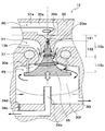
- FIG. 4 is a sectional view taken along line IV-IV in FIG. 2.
- It is a Mollier diagram which shows the state of the refrigerant
- It is an axial sectional view of an ejector of a 2nd embodiment of this indication. It is an axial sectional view of an ejector of a 3rd embodiment of this indication.
- the ejector 13 of the present embodiment is applied to a vapor compression refrigeration cycle apparatus including an ejector as a refrigerant decompression apparatus, that is, an ejector refrigeration cycle 10. Furthermore, this ejector-type refrigeration cycle 10 is applied to a vehicle air conditioner, and fulfills a function of cooling blown air that is blown into a vehicle interior that is a space to be air-conditioned.
- the compressor 11 sucks the refrigerant and discharges it until it becomes a high-pressure refrigerant.
- the compressor 11 of the present embodiment is an electric compressor configured by housing a fixed capacity type compression mechanism 11a and an electric motor 11b for driving the compression mechanism 11a in one housing.
- the compression mechanism 11a various compression mechanisms such as a scroll type compression mechanism and a vane type compression mechanism can be adopted. Further, the electric motor 11b is controlled in its operation (number of rotations) by a control signal output from a control device to be described later, and may adopt either an AC motor or a DC motor.
- the refrigerant inlet side of the condenser 12 a of the radiator 12 is connected to the discharge port of the compressor 11.
- the radiator 12 is a heat exchanger for heat radiation that radiates and cools the high-pressure refrigerant by exchanging heat between the high-pressure refrigerant discharged from the compressor 11 and outside air (outside air) blown by the cooling fan 12d. .
- the radiator 12 is a condensing unit that exchanges heat between the high-pressure gas-phase refrigerant discharged from the compressor 11 and the outside air blown from the cooling fan 12d to radiate and condense the high-pressure gas-phase refrigerant.
- 12a a receiver 12b that separates the gas-liquid refrigerant flowing out of the condensing unit 12a and stores excess liquid-phase refrigerant, and a liquid-phase refrigerant that flows out of the receiver unit 12b and the outside air blown from the cooling fan 12d exchange heat.
- This is a so-called subcool condenser that includes a supercooling section 12c that supercools the liquid-phase refrigerant.
- the ejector refrigeration cycle 10 employs an HFC-based refrigerant (specifically, R134a) as a refrigerant, and constitutes a subcritical refrigeration cycle in which the high-pressure side refrigerant pressure does not exceed the refrigerant critical pressure.
- an HFO refrigerant specifically, R1234yf
- refrigeration oil for lubricating the compressor 11 is mixed in the refrigerant, and a part of the refrigeration oil circulates in the cycle together with the refrigerant.
- the cooling fan 12d is an electric blower in which the rotation speed (the amount of blown air) is controlled by a control voltage output from the control device.
- a refrigerant inlet 31 a of the ejector 13 is connected to the refrigerant outlet side of the supercooling portion 12 c of the radiator 12.
- the ejector 13 functions as a refrigerant decompression device that decompresses the supercooled high-pressure liquid-phase refrigerant that has flowed out of the radiator 12 and causes the refrigerant to flow downstream, and is also described later by the suction action of the refrigerant flow injected at a high speed. It functions as a refrigerant circulating means (refrigerant transporting means) that sucks (transports) and circulates the refrigerant flowing out of the evaporator 14 that circulates. Furthermore, the ejector 13 of the present embodiment also functions as a gas-liquid separator that separates the gas-liquid of the refrigerant whose pressure has been reduced.
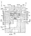
- FIG. 2 is a schematic cross-sectional view for explaining the function of each refrigerant passage of the ejector 13, and the same parts as those in FIG. 2 are denoted by the same reference numerals.
- the ejector 13 of the present embodiment includes a body 30 configured by combining a plurality of constituent members.
- the body 30 has a housing body 31 that is formed of a metal having a prismatic appearance and forms an outer shell of the ejector 13.
- a nozzle body 32, a middle body 33, a lower body are formed inside the housing body 31, a nozzle body 32, a middle body 33, a lower body are formed. 34 etc. are fixed and comprised.
- the housing body 31 includes a refrigerant inlet 31 a that allows the refrigerant flowing out of the radiator 12 to flow into the interior, a refrigerant suction port 31 b that sucks the refrigerant flowing out of the evaporator 14, and a gas-liquid separation space formed inside the body 30.
- the liquid-phase refrigerant outlet 31c that causes the liquid-phase refrigerant separated in 30f to flow out to the refrigerant inlet side of the evaporator 14 and the gas-phase refrigerant separated in the gas-liquid separation space 30f flow out to the suction side of the compressor 11.
- the gas-phase refrigerant outlet 31d to be made is formed.
- the nozzle body 32 is formed of a substantially conical metal member that tapers in the refrigerant flow direction, and is press-fitted into the housing body 31 such that the axial direction is parallel to the vertical direction (vertical direction in FIG. 2). It is fixed by means. Between the upper side of the nozzle body 32 and the housing body 31, a swirling space 30a for swirling the refrigerant flowing from the refrigerant inlet 31a is formed.
- the swirling space 30a is formed in a rotating body shape, and the central axis shown by the one-dot chain line in FIG. 2 extends in the vertical direction.
- the rotating body shape is a three-dimensional shape formed when a plane figure is rotated around one straight line (central axis) on the same plane. More specifically, the swirl space 30a of the present embodiment is formed in a substantially cylindrical shape. Of course, you may form in the shape etc. which combined the cone or the truncated cone, and the cylinder.
- the refrigerant inflow passage 31e that connects the refrigerant inlet 31a and the swirling space 30a extends in the tangential direction of the inner wall surface of the swirling space 30a when viewed from the central axis direction of the swirling space 30a.
- the refrigerant that has flowed into the swirl space 30a from the refrigerant inflow passage 31e flows along the inner wall surface of the swirl space 30a and swirls in the swirl space 30a.
- the refrigerant inflow passage 31e does not need to be formed so as to completely coincide with the tangential direction of the swirl space 30a when viewed from the central axis direction of the swirl space 30a, and at least in the tangential direction of the swirl space 30a. As long as a component is included, it may be formed including a component in another direction (for example, a component in the axial direction of the swirling space 30a).
- the refrigerant pressure on the central axis side is lower than the refrigerant pressure on the outer peripheral side in the swirling space 30a. Therefore, in the present embodiment, during normal operation of the ejector refrigeration cycle 10, the refrigerant pressure on the central axis side in the swirling space 30a is set to the pressure that becomes the saturated liquid phase refrigerant, or the refrigerant boils under reduced pressure (causes cavitation). The pressure is lowered to the pressure.
- Such adjustment of the refrigerant pressure on the central axis side in the swirling space 30a can be realized by adjusting the swirling flow velocity of the refrigerant swirling in the swirling space 30a.
- the swirl flow rate can be adjusted by adjusting the area ratio between the passage sectional area of the refrigerant inflow passage 31e and the vertical sectional area in the axial direction of the swirling space 30a, for example.
- the swirling flow velocity in the present embodiment means the flow velocity in the swirling direction of the refrigerant in the vicinity of the outermost peripheral portion of the swirling space 30a.
- a decompression space 30b is formed in which the refrigerant that has flowed out of the swirling space 30a is decompressed and flows downstream.
- the decompression space 30b is formed in a rotating body shape in which a cylindrical space and a frustoconical space that continuously spreads from the lower side of the cylindrical space and gradually expands in the refrigerant flow direction.
- the central axis of the working space 30b is arranged coaxially with the central axis of the swirling space 30a.
- a minimum passage area portion 30m having the smallest refrigerant passage area in the decompression space 30b, and a passage forming member 35 that changes the passage area of the minimum passage area portion 30m.
- the passage forming member 35 is formed in a substantially conical shape that gradually expands toward the downstream side of the refrigerant flow, and the central axis thereof is arranged coaxially with the central axis of the decompression space 30b.
- the passage forming member 35 is formed in a conical shape whose cross-sectional area increases as the distance from the decompression space 30b increases.
- the refrigerant passage formed between the inner peripheral surface of the portion forming the pressure reducing space 30b of the nozzle body 32 and the upper outer peripheral surface of the passage forming member 35 is formed with a tapered portion 131 and a divergent portion 132.
- the tapered portion 131 is a refrigerant passage that is formed on the upstream side of the refrigerant flow with respect to the minimum passage area portion 30m and gradually reduces the refrigerant passage area.
- the divergent portion 132 is a refrigerant passage that is formed on the downstream side of the refrigerant flow from the minimum passage area portion 30m so that the refrigerant passage area gradually increases.
- the decompression space 30b and the passage forming member 35 are overlapped (overlapped) when viewed from the radial direction, so that the shape of the axial cross section of the refrigerant passage is annular (large diameter circle).
- the shape is a donut shape excluding a small-diameter circular shape arranged coaxially.
- the spread angle of the passage forming member 35 of the present embodiment is smaller than the spread angle of the frustoconical space of the decompression space 30b, the refrigerant passage area in the divergent portion 132 is directed toward the downstream side of the refrigerant flow. Gradually expanding.
- a refrigerant passage formed between the inner peripheral surface of the pressure reducing space 30b and the outer peripheral surface on the top side of the passage forming member 35 is formed as a nozzle passage 13a functioning as a nozzle by this passage shape, and the refrigerant is decompressed.
- the flow rate of the refrigerant is increased so as to be the sonic velocity and injected.
- the refrigerant flowing into the nozzle passage 13a swirls in the swirling space 30a
- the refrigerant flowing through the nozzle passage 13a and the jet refrigerant injected from the nozzle passage 13a are the same as the refrigerant swirling in the swirling space 30a. It has a velocity component in the direction of turning in the direction.
- the middle body 33 is provided with a rotating body-shaped through hole penetrating the front and back at the center, and driving the passage forming member 35 to be displaced to the outer peripheral side of the through hole. It is formed of a metal disk-like member that accommodates the device 37.
- the central axis of the through hole of the middle body 33 is arranged coaxially with the central axes of the swirl space 30a and the decompression space 30b.
- the middle body 33 is fixed inside the housing body 31 and below the nozzle body 32 by means such as press fitting.
- an inflow space 30c is formed between the upper surface of the middle body 33 and the inner wall surface of the housing body 31 opposite to the middle body 33 for retaining the refrigerant flowing in from the refrigerant suction port 31b.
- the inflow space 30c is viewed from the central axis direction of the swirl space 30a and the decompression space 30b. It is formed in an annular cross section.
- the suction refrigerant inflow passage 30h that connects the refrigerant suction port 31b and the inflow space 30c extends in the tangential direction of the inner peripheral wall surface of the inflow space 30c when viewed from the central axis direction of the inflow space 30c. desirable.
- the reason for this is that the refrigerant flowing into the inflow space 30c from the refrigerant suction port 31b via the suction refrigerant inflow passage 30h is swung in the same direction as the refrigerant in the swirling space 30a, so This is because the swirling flow of the refrigerant flowing into the space 30e can be promoted.
- the lower side of the nozzle body 32 is inserted, that is, in the range where the middle body 33 and the nozzle body 32 overlap when viewed from the radial direction perpendicular to the axis, the taper tip of the nozzle body 32 is formed.
- the refrigerant passage area gradually decreases in the refrigerant flow direction so as to conform to the outer peripheral shape.
- a suction passage 30d is formed between the inner peripheral surface of the through hole and the outer peripheral surface on the lower side of the nozzle body 32 so as to communicate the inflow space 30c and the downstream side of the refrigerant flow in the decompression space 30b.
- the suction passage 13b for sucking the refrigerant from the outside through the refrigerant suction port 31b is formed by the suction refrigerant inflow passage 30h, the inflow space 30c, and the suction passage 30d. Furthermore, the central axis vertical cross section of the suction passage 13b is also formed in an annular shape, and the suction refrigerant flows while swirling from the outer peripheral side to the inner peripheral side of the central shaft in the suction passage 13b.
- a pressure increasing space 30e formed in a substantially truncated cone shape gradually spreading in the refrigerant flow direction is formed on the downstream side of the refrigerant flow in the suction passage 30d.
- the pressurizing space 30e is a space where the refrigerant injected from the nozzle passage 13a and the suction refrigerant sucked from the suction passage 30d are mixed.
- the lower side of the passage forming member 35 described above is disposed. Further, the expansion angle of the conical side surface of the passage forming member 35 in the pressure increasing space 30e is smaller than the expansion angle of the frustoconical space of the pressure increasing space 30e. The flow gradually expands toward the downstream side.
- a diffuser passage 13c functioning as a diffuser, and the velocity energy of the mixed refrigerant of the injection refrigerant and the suction refrigerant is converted into pressure energy. That is, in the diffuser passage 13c, the injection refrigerant and the suction refrigerant are mixed and pressurized.
- the cross-sectional shape perpendicular to the central axis of the diffuser passage 13c is also formed in an annular shape, and the refrigerant flowing through the diffuser passage 13c has the same direction as the refrigerant swirling in the swirling space 30a, as schematically shown in FIG. It has a speed component in the direction of turning.
- the drive device 37 disposed inside the middle body 33 and displacing the passage forming member 35 will be described.
- the drive device 37 is configured to include a circular thin plate diaphragm 37a which is a pressure responsive member. More specifically, as shown in FIG. 2, the diaphragm 37a is fixed by means such as welding so as to partition a cylindrical space formed on the outer peripheral side of the middle body 33 into two upper and lower spaces.
- the space on the upper side constitutes an enclosed space 37b in which a temperature-sensitive medium whose pressure changes according to the temperature of the refrigerant flowing out of the evaporator 14 is enclosed.
- a temperature-sensitive medium having the same composition as the refrigerant circulating in the ejector refrigeration cycle 10 is enclosed in the enclosed space 37b so as to have a predetermined density. Therefore, the temperature sensitive medium in the present embodiment is a medium mainly composed of R134a.
- the lower space of the two spaces partitioned by the diaphragm 37a constitutes an introduction space 37c for introducing the refrigerant flowing out of the evaporator 14 through a communication path (not shown). Therefore, the temperature of the refrigerant flowing out of the evaporator 14 is transmitted to the temperature-sensitive medium enclosed in the enclosure space 37b via the lid member 37d and the diaphragm 37a that partition the inflow space 30c and the enclosure space 37b.
- the suction passage 13 b is disposed on the upper side of the middle body 33 of the present embodiment, and the diffuser is disposed in the range from the central axis side to the lower side of the middle body 33.
- a passage 13c is arranged. Therefore, at least a part of the drive device 37 is disposed at a position sandwiched between the suction passage 13b and the diffuser passage 13c when viewed in the radial direction of the axis.
- the enclosed space 37b of the drive device 37 is a position where it overlaps with the suction passage 13b and the diffuser passage 13c when viewed from the central axis direction of the swivel space 30a, the passage forming member 35, etc., and the suction passage 13b. And it arrange
- the diaphragm 37a is deformed according to the differential pressure between the internal pressure of the enclosed space 37b and the pressure of the refrigerant flowing out of the evaporator 14 flowing into the introduction space 37c.
- the diaphragm 37a is preferably formed of a tough material having high elasticity and good heat conduction, and is preferably formed of a thin metal plate such as stainless steel (SUS304).
- a columnar actuating rod 37e is joined to the center portion of the diaphragm 37a by means such as welding, and the lower end side of the actuating rod 37e is the outermost side on the lowermost side (bottom side) of the passage forming member 35. It is fixed. Thereby, the diaphragm 37a and the passage forming member 35 are connected, and the passage forming member 35 is displaced in accordance with the displacement of the diaphragm 37a, and the refrigerant passage area of the nozzle passage 13a (passage sectional area in the minimum passage area portion 30m) is adjusted.
- the saturation pressure of the temperature-sensitive medium enclosed in the enclosed space 37b rises and is introduced from the internal pressure of the enclosed space 37b.
- the differential pressure obtained by subtracting the pressure in the space 37c increases.
- the diaphragm 37a displaces the channel
- the diaphragm 37a displaces the passage forming member 35 in a direction (vertical direction upper side) in which the passage sectional area in the minimum passage area portion 30m is reduced.
- the diaphragm 37a moves the passage forming member 35 in the vertical direction according to the temperature of the refrigerant flowing out of the evaporator 14, so that the degree of superheat of the refrigerant flowing out of the evaporator 14 approaches a predetermined value.
- the cross-sectional area of the passage area 30m can be adjusted.
- the gap between the operating rod 37e and the middle body 33 is sealed by a sealing member such as an O-ring (not shown), and the refrigerant does not leak from the gap even if the operating rod 37e is displaced.
- the bottom surface of the passage forming member 35 receives a load of a coil spring 40 fixed to the lower body 34.
- the coil spring 40 applies a load that urges the passage forming member 35 to reduce the passage cross-sectional area in the minimum passage area portion 30m, and the valve opening of the passage forming member 35 is adjusted by adjusting this load. It is also possible to change the target superheat by changing the pressure.
- a plurality of (specifically, two) cylindrical spaces are provided on the outer peripheral side of the middle body 33, and a circular thin plate-like diaphragm 37a is fixed inside each of these spaces to drive two drives.
- the apparatus 37 is comprised, the number of the drive apparatuses 37 is not limited to this.
- a diaphragm formed by an annular thin plate is fixed in a space formed in an annular shape when viewed from the axial direction, and the diaphragm and the passage forming member 35 are connected by a plurality of operating rods. Also good.
- the lower body 34 is formed of a metal cylindrical member, and is fixed in the housing body 31 by means such as screwing so as to close the bottom surface of the housing body 31.
- a gas-liquid separation space 30f is formed between the upper surface side of the lower body 34 and the bottom surface side of the middle body 33 to separate the gas and liquid of the refrigerant flowing out from the diffuser passage 13c.
- the gas-liquid separation space 30f is formed as a substantially cylindrical rotary body-shaped space, and the central axis of the gas-liquid separation space 30f is also arranged coaxially with the central axes of the swirl space 30a, the decompression space 30b, and the like. Has been.
- the refrigerant flows while swirling along the refrigerant passage having an annular cross section. Therefore, the refrigerant flowing from the diffuser passage 13c into the gas-liquid separation space 30f also has a velocity component in the swirling direction. is doing. Accordingly, the gas-liquid refrigerant is separated by centrifugal force in the gas-liquid separation space 30f. Further, the internal volume of the gas-liquid separation space 30f is such that even if a load fluctuation occurs in the cycle and the refrigerant circulation flow rate circulating in the cycle fluctuates, the surplus refrigerant cannot be substantially accumulated. .
- a cylindrical pipe 34a that is arranged coaxially with the gas-liquid separation space 30f and extends upward. Therefore, the liquid phase refrigerant separated in the gas-liquid separation space 30f temporarily stays on the outer peripheral side of the pipe 34a and flows out from the liquid phase refrigerant outlet 31c.
- a gas phase refrigerant outflow passage 34b is formed in the pipe 34a to guide the gas phase refrigerant separated in the gas-liquid separation space 30f to the gas phase refrigerant outlet 31d.
- the gas is separated in the gas-liquid separation space 30f on the lower side of the inner peripheral wall surface forming the gas-liquid separation space 30f of the housing body 31 (the side forming the space in which the separated liquid-phase refrigerant is stored).
- An inlet portion 30j of a liquid phase refrigerant outflow passage 30i that guides the liquid phase refrigerant to the liquid phase refrigerant outlet 31c is formed.
- the coil spring 40 described above is fixed to the upper end of the pipe 34a.
- the coil spring 40 also functions as a vibration buffer member that attenuates the vibration of the passage forming member 35 caused by pressure pulsation when the refrigerant is depressurized.
- an inlet 34d of the oil return passage 34c is opened at a portion of the lower body 34 formed in a columnar shape on the outer peripheral side of the pipe 34a, that is, a portion forming the bottom of the gas-liquid separation space 30f.
- the oil return passage 34c is a refrigerant passage that guides the liquid-phase refrigerant separated in the gas-liquid separation space 30f and mixed with refrigerating machine oil to the gas-phase refrigerant outflow passage 34b, and is parallel to the axial direction of the gas-liquid separation space 30f. It is formed in a shape that extends.
- the oil return passage 34 extends in parallel with the axial direction of the passage forming member 35.
- the inlet portion 34d of the oil return passage 34c is arranged at a position closer to the outer peripheral side of the gas-liquid separation space 30f than the axial center of the passage forming member 35, as shown in the sectional view of FIG.
- the outlet 34e of the oil return passage 34c is open in the gas-phase refrigerant outflow passage 34b.
- a line segment L1 extending from the axial center of the passage forming member 35 toward the center of the inlet portion 30j of the liquid-phase refrigerant outflow passage 30i and the passage forming member 35
- a line segment L2 extending from the center of the shaft toward the center of the inlet 34d of the oil return passage 34c is disposed on the same straight line.
- the angle ⁇ formed between the line segment L1 and the line segment L2 is 180 °. Accordingly, as the angle formed between the line segment L1 and the line segment L2, the angle at which the inlet portion 30j of the liquid-phase refrigerant outflow passage 30i and the inlet portion 34d of the oil return passage 34c are separated from each other is adopted. Become.
- the center of the inlet portion 30j of the liquid phase refrigerant outlet passage 30i, the oil return passage As the center of the inlet portion 34d of 34c, the center of gravity of the passage section of each of the inlet portions 30j and 34c may be adopted.
- the inlet side of the evaporator 14 is connected to the liquid-phase refrigerant outlet 31 c of the ejector 13.
- the evaporator 14 performs heat exchange between the low-pressure refrigerant decompressed by the ejector 13 and the blown air blown into the vehicle interior from the blower fan 14a, thereby evaporating the low-pressure refrigerant and exerting an endothermic effect. It is a vessel.
- the blower fan 14a is an electric blower in which the rotation speed (the amount of blown air) is controlled by a control voltage output from the control device.
- a refrigerant suction port 31 b of the ejector 13 is connected to the outlet side of the evaporator 14. Further, the suction side of the compressor 11 is connected to the gas-phase refrigerant outlet 31 d of the ejector 13.
- a control device includes a known microcomputer including a CPU, a ROM, a RAM, and the like and its peripheral circuits. This control device performs various calculations and processes based on the control program stored in the ROM, and controls the operations of the various electric actuators 11b, 12d, 14a and the like described above.
- control device includes an internal air temperature sensor that detects the temperature inside the vehicle, an external air temperature sensor that detects the outside air temperature, a solar radiation sensor that detects the amount of solar radiation in the vehicle interior, and an air temperature (evaporator temperature) of the evaporator 14.
- a sensor group for air conditioning control such as an evaporator temperature sensor to detect, an outlet side temperature sensor to detect the temperature of the radiator 12 outlet side refrigerant, and an outlet side pressure sensor to detect the pressure of the radiator 12 outlet side refrigerant are connected, Detection values of these sensor groups are input.
- an operation panel (not shown) disposed near the instrument panel in the front part of the vehicle interior is connected to the input side of the control device, and operation signals from various operation switches provided on the operation panel are input to the control device.
- various operation switches provided on the operation panel there are provided an air conditioning operation switch for requesting air conditioning in the vehicle interior, a vehicle interior temperature setting switch for setting the vehicle interior temperature, and the like.
- control device of the present embodiment is configured integrally with a control unit that controls the operation of various control target devices connected to the output side of the control device.
- a configuration (hardware and software) for controlling the operation constitutes a control unit of each control target device.
- operation of the electric motor 11b of the compressor 11 comprises the discharge capability control part.
- the vertical axis of the Mollier diagram shows pressures corresponding to P0, P1, and P2 in FIG.
- the control device operates the electric motor 11b, the cooling fan 12d, the blower fan 14a, and the like of the compressor 11.
- the compressor 11 sucks the refrigerant, compresses it, and discharges it.
- the high-temperature and high-pressure gas-phase refrigerant discharged from the compressor 11 flows into the condenser 12a of the radiator 12 and exchanges heat with the blown air (outside air) blown from the cooling fan 12d. , Dissipates heat and condenses.
- the refrigerant that has dissipated heat in the condensing unit 12a is gas-liquid separated in the receiver unit 12b.
- the liquid-phase refrigerant separated from the gas and liquid in the receiver unit 12b exchanges heat with the blown air blown from the cooling fan 12d in the supercooling unit 12c, and further dissipates heat to become a supercooled liquid-phase refrigerant (FIG. 5). a5 point ⁇ b5 point).
- the supercooled liquid-phase refrigerant that has flowed out of the supercooling portion 12c of the radiator 12 passes through the nozzle passage 13a formed between the inner peripheral surface of the decompression space 30b of the ejector 13 and the outer peripheral surface of the passage forming member 35.
- the pressure is reduced entropically and injected (b5 point ⁇ c5 point in FIG. 5).
- the refrigerant passage area in the minimum passage area portion 30m of the decompression space 30b is adjusted so that the superheat degree of the refrigerant on the outlet side of the evaporator 14 approaches a predetermined value.
- the refrigerant flowing out of the evaporator 14 is sucked through the refrigerant suction port 31b and the suction passage 13b (the inflow space 30c and the suction passage 30d) by the suction action of the injection refrigerant injected from the nozzle passage 13a. Further, the refrigerant injected from the nozzle passage 13a and the suction refrigerant sucked through the suction passage 13b and the like flow into the diffuser passage 13c (point c5 ⁇ d5, point h5 ⁇ d5 in FIG. 5).
- the velocity energy of the refrigerant is converted into pressure energy by expanding the refrigerant passage area.
- the pressure of the mixed refrigerant rises while the injected refrigerant and the suction refrigerant are mixed (point d5 ⁇ point e5 in FIG. 5).
- the refrigerant flowing out of the diffuser passage 13c is gas-liquid separated in the gas-liquid separation space 30f (point e5 ⁇ f5, point e5 ⁇ g5 in FIG. 5).
- the liquid refrigerant separated in the gas-liquid separation space 30f flows out from the liquid refrigerant outlet 31c and flows into the evaporator 14.
- the refrigerant flowing into the evaporator 14 absorbs heat from the blown air blown by the blower fan 14a and evaporates, and the blown air is cooled (g5 point ⁇ h5 point in FIG. 5).
- the gas-phase refrigerant separated in the gas-liquid separation space 30f flows out of the gas-phase refrigerant outlet 31d, is sucked into the compressor 11, and is compressed again (point f5 ⁇ a5 in FIG. 5).
- the ejector refrigeration cycle 10 of the present embodiment operates as described above, and can cool the blown air blown into the vehicle interior. Further, in the ejector refrigeration cycle 10, since the refrigerant whose pressure has been increased in the diffuser passage 13c is sucked into the compressor 11, the driving power of the compressor 11 can be reduced and cycle efficiency (COP) can be improved. .
- COP cycle efficiency
- the refrigerant pressure on the swivel center side in the swirl space 30a is reduced to the pressure that becomes a saturated liquid phase refrigerant, or the refrigerant is depressurized.
- the pressure can be reduced to boiling (causing cavitation).
- the gas phase refrigerant is present in the swirl space 30a in the vicinity of the swirl center line, and the liquid single phase is surrounded by the two-phase separation so that a larger amount of gas-phase refrigerant exists on the inner periphery side than the outer periphery side of the swirl center shaft.
- the wall surface boiling that occurs when the refrigerant is separated from the outer peripheral side wall surface of the annular refrigerant passage and Boiling of the refrigerant is promoted by interfacial boiling by boiling nuclei generated by cavitation of the refrigerant on the central axis side of the annular refrigerant passage.
- the refrigerant flowing into the minimum passage area 30m of the nozzle passage 13a is in a gas-liquid mixed state in which the gas phase and the liquid phase are uniformly mixed.
- the flow of refrigerant in the gas-liquid mixed state is choked in the vicinity of the minimum passage area portion 30m, and the gas-liquid mixed state refrigerant that has reached the speed of sound by this choking is accelerated by the divergent portion 132 and injected.
- the energy conversion efficiency (equivalent to nozzle efficiency) in the nozzle passage 13a is improved by efficiently accelerating the refrigerant in the gas-liquid mixed state to the sound speed by promoting boiling by both wall surface boiling and interface boiling. Can do.
- the passage forming member 35 is formed in a conical shape in which the cross-sectional area increases with distance from the decompression space 30b, and the cross-sectional shape of the diffuser passage 13c is annular. Therefore, the shape of the diffuser passage 13c can be made to expand along the outer periphery of the passage forming member 35 as the distance from the decompression space 30b increases, and the refrigerant flowing through the diffuser passage 13c is swirled. be able to.
- the diffuser passage 13c is compared with the case where the diffuser portion is formed in a shape extending in the axial direction of the nozzle portion. It can be suppressed that the dimension in the axial direction (the axial direction of the passage forming member 35) increases. As a result, an increase in size of the ejector 13 as a whole can be suppressed.
- the body 30 of the ejector 13 of the present embodiment is formed with a gas-liquid separation space 30f for separating the gas-liquid of the refrigerant flowing out from the diffuser passage 13c, a gas-liquid separation device is provided separately from the ejector 13. In contrast, the volume of the gas-liquid separation space 30f can be effectively reduced.
- the refrigerant flowing out from the diffuser passage 13c formed in an annular cross section has already swirled, so that a swirling flow of the refrigerant is generated or grows in the gas-liquid separation space 30f.
- the volume of the gas-liquid separation space 30f can be effectively reduced as compared with the case where a gas-liquid separation device is provided separately from the ejector 13.
- the inlet portion 34 d of the oil return passage 34 c that opens in the gas-liquid separation space 30 f is connected to the shaft of the passage forming member 35. It is arranged at a position closer to the outer peripheral side than the center. In other words, in the radial direction of the passage forming member 35, the distance from the inlet portion 34d of the oil return passage 34c to the axial center of the passage forming member 35 is larger than the distance from the inlet portion 34d to the outer peripheral side of the gas-liquid separation space 30f. It is getting longer.
- the cross-sectional shape of the diffuser passage 13c is formed in an annular shape, and the diffuser passage is formed in a shape that gradually spreads toward the outer peripheral side toward the downstream side of the refrigerant flow, or by the action of centrifugal force, the gas-liquid separation space
- the liquid refrigerant that is unevenly distributed on the outer peripheral side of 30f can be efficiently allowed to flow into the oil return passage 34c.
- the liquid phase refrigerant mixed with the refrigerating machine oil can be discharged to the suction side of the compressor 11 through the gas phase refrigerant outflow passage 34b.
- a gas-liquid separator-integrated ejector capable of appropriately flowing the liquid refrigerant mixed with the refrigerating machine oil separated in the gas-liquid separation space 30f to the outside is realized. can do.
- the line segment L1 extending from the axial center of the passage forming member 35 toward the center of the inlet portion 30j of the liquid-phase refrigerant outflow passage 30i and the oil return from the axial center of the passage forming member 35 are provided. Since the line segment L2 extending toward the center of the inlet portion 34d of the passage 34c is arranged on the same straight line, the gas-phase refrigerant separated in the gas-liquid separation space 30f flows into the oil return passage 34c. This can be effectively suppressed.
- the liquid level of the liquid phase refrigerant in the gas-liquid separation space 30f is likely to decrease in the vicinity of the inlet 30j of the liquid phase refrigerant outflow passage 30i. That is, if the line segment L1 and the line segment L2 are arranged so as to be in a straight line, the inlet portion 34d of the oil return passage 34c can be arranged at a position away from the inlet portion 30j of the liquid-phase refrigerant outflow passage 30i. Further, it is possible to suppress a decrease in the liquid level of the liquid-phase refrigerant in the vicinity of the inlet portion 34d of the oil return passage 34c.
- the passage forming member 35 is displaced according to the load fluctuation of the ejector refrigeration cycle 10, and the refrigerant passage of the nozzle passage 13a and the diffuser passage 13c.
- the area can be adjusted. Therefore, the ejector 13 can be appropriately operated in accordance with the load fluctuation of the ejector refrigeration cycle 10.
- the enclosed space 37b in which the temperature sensitive medium is enclosed is disposed at a position sandwiched between the suction passage 13b and the diffuser passage 13c, and therefore, between the suction passage 13b and the diffuser passage 13c.
- the space formed can be effectively used. As a result, the enlargement of the physique as the whole ejector can be further suppressed.
- the enclosed space 37b is disposed at a position surrounded by the suction passage 13b and the diffuser passage 13c, the temperature of the refrigerant flowing out of the evaporator 14 flowing through the suction passage 13b without being affected by the outside air temperature or the like. Can be satisfactorily transmitted to the temperature sensitive medium, and the pressure in the enclosed space 37b can be changed. That is, the pressure in the enclosed space 37b can be accurately changed according to the temperature of the refrigerant flowing out of the evaporator 14.
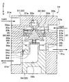
- the pressure of the refrigerant flowing out from the outlet portion 34e of the oil return passage 34c in the gas-phase refrigerant outflow passage 34b of the ejector 13 is reduced as shown in the cross-sectional view of FIG.
- An orifice 36 which is an example of the outflow passage side pressure reducing device to be made is disposed. More specifically, the orifice 36 reduces the refrigerant pressure flowing out from the outlet portion 34e of the oil return passage 34c by reducing the cross-sectional area of the gas-phase refrigerant outflow passage 34b.
- the ejector 13 of the present embodiment includes the orifice 36, the refrigerant pressure at the outlet portion 34e can be made lower than the refrigerant pressure at the inlet portion 34d of the oil return passage 34c. Therefore, the liquid refrigerant mixed with the refrigerating machine oil can surely flow out to the suction side of the compressor 11. Furthermore, the flow rate of the liquid-phase refrigerant returned to the suction side of the compressor 11 via the oil return passage 34c can be appropriately adjusted by appropriately setting the pressure reduction amount in the orifice 36.
- a liquid storage hole 34f is provided as shown in the cross-sectional view of FIG. 7 in contrast to the first embodiment.
- the liquid storage hole 34f is subjected to a counterbore process on the upper surface of the lower body 34 on the outer peripheral side of the pipe 34a, that is, the bottom surface of the gas-liquid separation space 30f, and the bottom surface is depressed downward. Is formed by.
- the liquid storage hole 34f forms the lowermost space of the gas-liquid separation space 30f therein, and the liquid phase separated in the gas-liquid separation space 30f is stored in the liquid storage hole 34f.
- the refrigerant will flow preferentially.
- the inner diameter of the liquid storage hole 34f is formed larger than the diameter of the oil return path 34c, and the inlet 34d of the oil return path 34c of the present embodiment opens at the bottom surface of the liquid storage hole 34f. .
- a liquid storage hole 34f is provided in a portion forming the bottom surface of the gas-liquid separation space 30f, and the inlet portion 34d of the oil return passage 34c is opened in the liquid storage hole 34f.
- the liquid storage hole 34f may be applied to the ejector 13 including the orifice 36 as an example of the outflow passage side pressure reducing device of the second embodiment.
- the turning promoting portion that promotes the turning of the refrigerant flowing out from the diffuser passage 13 c around the axis of the passage forming member 35.
- the example which added the some baffle plate 38 which is an example is demonstrated.
- FIG. 8A the turning promoting portion that promotes the turning of the refrigerant flowing out from the diffuser passage 13 c around the axis of the passage forming member 35.
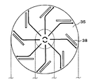
- the rectifying plate 38 is disposed on the outer peripheral side of the lowermost portion of the passage forming member 35 and at a portion forming the refrigerant outlet side of the diffuser passage 13c. Further, the rectifying plate 38 is constituted by a plate-like member that extends in the axial direction of the passage forming member 35, and is arranged in an annular shape around the axis of the passage forming member 35 as shown in FIG. 8A.
- each rectifying plate 38 is arranged such that its plate surface is inclined with respect to the radial direction when viewed from the axial direction. Then, the refrigerant flowing out of the diffuser passage 13c flows along the plate surface of each rectifying plate 38, whereby the flow of the refrigerant flowing out of the diffuser passage 13c in the swirling direction is promoted.
- Other configurations and operations are the same as those in the first embodiment. Therefore, the same effect as that of the first embodiment can be obtained in the ejector 13 of the present embodiment.
- the speed component in the swirl direction among the speed components of the refrigerant flowing through the diffuser passage 13c. May become extremely small with respect to the velocity component in the axial direction, or the velocity component in the turning direction may be almost eliminated.
- the ejector refrigeration cycle 10 of the ejector refrigeration cycle 10 is provided as shown by thick solid arrows in FIGS. 8A and 8B. Regardless of the operating conditions, the refrigerant flowing into the gas-liquid separation space 30 f can be swung around the axis of the passage forming member 35. Therefore, a centrifugal force can be reliably applied to the refrigerant in the gas-liquid separation space 30f.
- the gas-liquid of the refrigerant flowing into the gas-liquid separation space 30f can be reliably separated regardless of the operating conditions of the ejector refrigeration cycle 10, and the separated liquid phase
- the refrigerant can be reliably distributed on the outer peripheral side of the gas-liquid separation space 30f and flow into the oil return passage 34c.
- the rectifying plate 38 formed in a flat plate shape is described, but the rectifying plate 38 is not limited to this. As long as it can accelerate
- the arrangement of the plurality of rectifying plates 38 is so-called that the interval between the rectifying plates 38 on the refrigerant flow outlet side is wider than the interval between the rectifying plates 38 on the inlet side. Deceleration blade row arrangement. According to this, the passage cross-sectional area of the refrigerant passage formed between the adjacent rectifying plates 38 can be gradually enlarged to function as a diffuser that converts the velocity energy of the refrigerant into pressure energy.
- the arrangement of the rectifying plates 38 is not limited to this, and a so-called speed-up blade row arrangement in which the interval between the rectifying plates 38 on the refrigerant flow outlet side is narrower than the interval between the rectifying plates 38 on the inlet side ( (Acceleration cascade arrangement). According to this, it is possible to gradually reduce the passage cross-sectional area of the refrigerant passage formed between the adjacent rectifying plates 38 and increase the flow velocity of the refrigerant in the swirling direction. Can be promoted.
- the inlet 34d of the oil return passage 34c is disposed at a position closer to the outer peripheral side of the gas-liquid separation space 30f than the axial center of the passage forming member 35.
- it may be disposed at a portion forming the cylindrical side surface of the gas-liquid separation space 30f of the housing body 31 or may be disposed on the cylindrical side surface of the pipe 34a of the lower body 34.
- the detailed configuration of the liquid-phase refrigerant outflow passage 30i that connects the gas-liquid separation space 30f and the liquid-phase refrigerant outlet 31c is not described. As shown in the sectional view of FIG. 9, it may extend in the tangential direction of the inner peripheral wall surface of the gas-liquid separation space 30f. Thereby, the kinetic energy of the refrigerant swirling in the gas-liquid separation space 30f can be effectively used to allow the refrigerant to flow out to the evaporator 14 side.
- the line segment L1 and the line segment L2 may be arranged on the same straight line as shown in FIG. In other words, the angle ⁇ formed between the line segment L1 and the line segment L2 may be arranged to be 180 °.
- the gas-phase refrigerant flows into the oil return passage 34c. It has been found that it can be sufficiently suppressed.
- the angle formed between the line segment L1 and the line segment L2 is 90 ° or more.
- two oil return passages 34c and two liquid-phase refrigerant outflow passages 30i may be arranged as shown in FIG.
- FIGS. 9 and 10 are drawings corresponding to FIG. 4 of the first embodiment.
- a decompression device for example, a side made of an orifice or a capillary tube
- a fixed aperture may be arranged.
- a fixed throttle may be added to the liquid-phase refrigerant outlet 31c, and the ejector 13 may be applied to an ejector refrigeration cycle including a two-stage booster compressor.
- thermowax that changes in volume depending on temperature
- a drive device that includes a shape memory alloy elastic member may be used as the drive device.
- a device that displaces the passage forming member 35 by an electric mechanism such as an electric motor or a solenoid may be employed.
- the passage forming member 35 may be formed of metal (for example, aluminum) or may be formed of resin.
- the drive device 37 can be reduced in size, and the physique of the ejector 13 as a whole can be further reduced in size.
- the ejector refrigeration cycle 10 including the ejector 13 of the present disclosure is applied to a vehicle air conditioner.
- the application of the ejector refrigeration cycle 10 including the ejector 13 of the present disclosure is described. Is not limited to this.
- the present invention may be applied to a stationary air conditioner, a cold storage container, a cooling / heating device for a vending machine, and the like.
Landscapes
- Engineering & Computer Science (AREA)
- Physics & Mathematics (AREA)
- Mechanical Engineering (AREA)
- General Engineering & Computer Science (AREA)
- Fluid Mechanics (AREA)
- Thermal Sciences (AREA)
- Jet Pumps And Other Pumps (AREA)
- Heat-Exchange Devices With Radiators And Conduit Assemblies (AREA)
Abstract
Description
エジェクタ式冷凍サイクルに適用されるエジェクタであって、
放熱器から流出した冷媒を旋回させる旋回空間、この旋回空間から流出した冷媒を減圧させる減圧用空間、減圧用空間の冷媒流れ下流側に連通して蒸発器から流出した冷媒を吸引する吸引用通路、および減圧用空間から噴射された噴射冷媒と吸引用通路から吸引された吸引冷媒とを混合して昇圧させる昇圧用空間が形成されたボデーと、
少なくとも一部が減圧用空間の内部および昇圧用空間の内部に配置されて、減圧用空間から離れるに伴って断面積が拡大する円錐状に形成された通路形成部材とを備え、
ボデーのうち減圧用空間を形成する部位の内周面と通路形成部材の外周面との間に形成される冷媒通路が、旋回空間から流出した冷媒を減圧させて噴射するノズルとして機能するノズル通路を形成し、
ボデーのうち昇圧用空間を形成する部位の内周面と通路形成部材の外周面との間に形成される冷媒通路が、噴射冷媒および吸引冷媒を混合して昇圧させるディフューザとして機能するディフューザ通路を形成し、
さらに、ボデーには、ディフューザ通路から流出した冷媒の気液を遠心力の作用によって分離する気液分離空間が形成されているエジェクタを提案している。
(第1実施形態)
図1~図5を用いて、本開示の第1実施形態を説明する。本実施形態のエジェクタ13は、図1に示すように、冷媒減圧装置としてエジェクタを備える蒸気圧縮式の冷凍サイクル装置、すなわち、エジェクタ式冷凍サイクル10に適用されている。さらに、このエジェクタ式冷凍サイクル10は、車両用空調装置に適用され、空調対象空間である車室内へ送風される送風空気を冷却する機能を果たす。
(第2実施形態)
本実施形態では、第1実施形態に対して、図6の断面図に示すように、エジェクタ13の気相冷媒流出通路34b内にオイル戻し通路34cの出口部34eから流出した冷媒の圧力を低下させる流出通路側減圧装置の一例であるオリフィス36を配置している。より具体的には、オリフィス36は、気相冷媒流出通路34b内の通路断面積を縮小させることによって、オイル戻し通路34cの出口部34eから流出した冷媒圧力を低下させている。
(第3実施形態)
本実施形態では、第1実施形態に対して、図7の断面図に示すように、貯液穴34fを設けている。具体的には、この貯液穴34fは、ロワーボデー34のうちパイプ34aの外周側の上面、すなわち気液分離空間30fの底面を形成する部位にザグリ加工を施し、底面を下方側に陥没させることによって形成されている。
(第4実施形態)
本実施形態では、第1実施形態のエジェクタ13に対して、図8A、8Bに示すように、ディフューザ通路13cから流出する冷媒が通路形成部材35の軸周りに旋回することを促進する旋回促進部の一例である複数の整流板38を追加した例を説明する。なお、図8Aでは、通路形成部材35を軸方向から見たときに、通路形成部材35の円錐状側面に沿って流れる冷媒の流れ方向を太実線矢印にて模式的に図示しており、整流板38等についても模式的に図示している。
Claims (7)
- 冷媒中に圧縮機潤滑用の冷凍機油が混入した蒸気圧縮式の冷凍サイクル装置に適用されるエジェクタであって、
冷媒流入口(31a)と、前記冷媒流入口(31a)から流入した冷媒を旋回させる旋回空間(30a)と、前記旋回空間(30a)から流出した冷媒を減圧させる減圧用空間(30b)と、前記減圧用空間(30b)の冷媒流れ下流側に連通して外部から冷媒を吸引する吸引用通路(13b)と、前記減圧用空間(30b)から噴射された噴射冷媒と前記吸引用通路(13b)から吸引された吸引冷媒とを混合させる昇圧用空間(30e)とを有するボデー(30)と、
前記減圧用空間(30b)の内部および前記昇圧用空間(30e)の内部に配置される少なくとも一部を有し、前記減圧用空間(30b)から離れるに伴って断面積が拡大する円錐形状を有する通路形成部材(35)とを備え、
前記ボデー(30)のうち前記減圧用空間(30b)を形成する部位の内周面と前記通路形成部材(35)の外周面との間に形成される冷媒通路は、前記旋回空間(30a)から流出した冷媒を減圧させて噴射するノズルとして機能するノズル通路(13a)であり、
前記ボデー(30)のうち前記昇圧用空間(30e)を形成する部位の内周面と前記通路形成部材(35)の外周面との間に形成される冷媒通路は、前記噴射冷媒および前記吸引冷媒との混合冷媒を昇圧させるディフューザとして機能するディフューザ通路(13c)であり、
前記ディフューザ通路(13c)は、前記通路形成部材(35)の軸方向に垂直な断面において環形状を有しており、
さらに、前記ボデー(30)は、前記ディフューザ通路(13c)から流出した冷媒の気液を遠心力の作用によって分離する気液分離空間(30f)と、前記気液分離空間(30f)にて分離された気相冷媒を前記圧縮機(11)の吸入側へ流出させる気相冷媒流出通路(34b)、および前記気液分離空間(30f)にて分離されて前記冷凍機油が混入した液相冷媒を前記気液分離空間(30f)から前記気相冷媒流出通路(34b)へ導くオイル戻し通路(34c)とを有しており、
前記オイル戻し通路(34c)は、前記気液分離空間(30f)内で開口する入口部(34d)を有し、
前記通路形成部材(35)の径方向において、前記オイル戻し通路(34c)の前記入口部(34d)から前記通路形成部材(35)の軸中心までの距離は、前記入口部(34d)から前記気液分離空間(30f)の外周側までの距離よりも長くなっているエジェクタ。 - 前記オイル戻し通路(34c)は、前記気相冷媒流出通路(34b)内で開口する出口部(34e)を有しており、
さらに、前記気相冷媒流出通路(34b)内で、前記出口部(34e)から流出した冷媒の圧力を低下させる流出通路側減圧装置(36)を備えている請求項1に記載のエジェクタ。 - 前記ボデー(30)は、前記気液分離空間(30f)の底面から陥没しており、前記気液分離空間(30f)にて分離された液相冷媒を気相冷媒に対して優先的に流入させる貯液穴(34f)を有しており、
前記オイル戻し通路(34c)の前記入口部(34d)は、前記貯液穴(34f)内で開口している請求項1または2に記載のエジェクタ。 - さらに、前記ボデー(30)は、前記気液分離空間(30f)にて分離された液相冷媒を流出させる液相冷媒流出通路(30i)を有しており、
前記液相冷媒流出通路(30i)は、前記気液分離空間(30f)内で開口する入口部(30j)を有しており、
前記通路形成部材(35)の軸方向に対して垂直な断面において、前記通路形成部材(35)の軸中心から前記液相冷媒流出通路(30i)の前記入口部(30j)の中心へ向かって延びる線分(L1)と、前記通路形成部材(35)の軸中心から前記オイル戻し通路(34c)の前記入口部(34d)の中心へ向かって延びる線分(L2)との間の角度(θ)が90°以上となっている請求項1ないし3のいずれか1つに記載のエジェクタ。 - 前記ディフューザ通路(13c)から流出する冷媒が前記通路形成部材(35)の軸周りに旋回することを促進する旋回促進部(38)をさらに備える請求項1ないし4のいずれか1つに記載のエジェクタ。
- 前記ディフューザ通路(13c)を流通する冷媒は、前記通路形成部材(35)の軸周りに旋回している請求項1ないし5のいずれか1つに記載のエジェクタ。
- 前記オイル戻し通路(34c)は、前記通路形成部材(35)の軸方向に平行に延びている請求項1ないし6のいずれか1つに記載のエジェクタ。
Priority Applications (3)
| Application Number | Priority Date | Filing Date | Title |
|---|---|---|---|
| CN201380067797.0A CN104903594B (zh) | 2012-12-27 | 2013-12-23 | 喷射器 |
| US14/655,745 US9618245B2 (en) | 2012-12-27 | 2013-12-23 | Ejector |
| DE112013006288.7T DE112013006288B4 (de) | 2012-12-27 | 2013-12-23 | Ejektor |
Applications Claiming Priority (4)
| Application Number | Priority Date | Filing Date | Title |
|---|---|---|---|
| JP2012-285640 | 2012-12-27 | ||
| JP2012285640 | 2012-12-27 | ||
| JP2013233017A JP6119566B2 (ja) | 2012-12-27 | 2013-11-11 | エジェクタ |
| JP2013-233017 | 2013-11-11 |
Publications (1)
| Publication Number | Publication Date |
|---|---|
| WO2014103276A1 true WO2014103276A1 (ja) | 2014-07-03 |
Family
ID=51020394
Family Applications (1)
| Application Number | Title | Priority Date | Filing Date |
|---|---|---|---|
| PCT/JP2013/007525 Ceased WO2014103276A1 (ja) | 2012-12-27 | 2013-12-23 | エジェクタ |
Country Status (5)
| Country | Link |
|---|---|
| US (1) | US9618245B2 (ja) |
| JP (1) | JP6119566B2 (ja) |
| CN (1) | CN104903594B (ja) |
| DE (1) | DE112013006288B4 (ja) |
| WO (1) | WO2014103276A1 (ja) |
Cited By (3)
| Publication number | Priority date | Publication date | Assignee | Title |
|---|---|---|---|---|
| US9625193B2 (en) | 2012-12-27 | 2017-04-18 | Denso Corporation | Ejector |
| US20170108256A1 (en) * | 2014-01-30 | 2017-04-20 | Carrier Corporation | Ejectors and Methods of Use |
| US9897354B2 (en) | 2013-07-30 | 2018-02-20 | Denso Corporation | Ejector |
Families Citing this family (10)
| Publication number | Priority date | Publication date | Assignee | Title |
|---|---|---|---|---|
| JP2016084966A (ja) * | 2014-10-24 | 2016-05-19 | 株式会社デンソー | エジェクタ式冷凍サイクル |
| JP6319043B2 (ja) | 2014-10-24 | 2018-05-09 | 株式会社デンソー | エジェクタ式冷凍サイクル |
| JP6319041B2 (ja) | 2014-10-24 | 2018-05-09 | 株式会社デンソー | エジェクタ式冷凍サイクル |
| JP2017020676A (ja) * | 2015-07-08 | 2017-01-26 | 株式会社デンソー | エジェクタ |
| CN107143533A (zh) * | 2015-12-07 | 2017-09-08 | 张玉良 | 节能喷射器 |
| EP3560581B1 (en) * | 2017-01-05 | 2022-10-26 | Ashizawa Finetech Ltd | Dispersion and defoaming device |
| GB2558627B (en) * | 2017-01-11 | 2020-02-26 | Transvac Systems Ltd | Ejector device |
| US11306950B2 (en) | 2017-07-28 | 2022-04-19 | Carrier Corporation | Lubrication supply system |
| KR102337120B1 (ko) * | 2019-12-31 | 2021-12-08 | 한국항공우주연구원 | 상분리 장치 |
| CN115573914B (zh) * | 2022-11-04 | 2025-09-05 | 珠海格力电器股份有限公司 | 一种排气组件、压缩机 |
Citations (11)
| Publication number | Priority date | Publication date | Assignee | Title |
|---|---|---|---|---|
| JPS59123700U (ja) * | 1983-02-10 | 1984-08-20 | 株式会社日立製作所 | エジエクタ− |
| JPS6176800A (ja) * | 1984-09-25 | 1986-04-19 | Sakou Giken:Kk | 蒸気エゼクタ− |
| JPH01250000A (ja) * | 1988-03-30 | 1989-10-05 | Kobe Steel Ltd | エジェクター装置 |
| JP2002333000A (ja) * | 2001-05-11 | 2002-11-22 | Nkk Corp | エジェクタおよび冷凍システム |
| JP2003515702A (ja) * | 1999-11-30 | 2003-05-07 | コミツサリア タ レネルジー アトミーク | 軸方向ドレインを具備した高圧水蒸気ディフューザ |
| JP2003336915A (ja) * | 2002-05-20 | 2003-11-28 | Nippon Soken Inc | エジェクタ方式の減圧装置 |
| JP2008008599A (ja) * | 2006-06-30 | 2008-01-17 | Denso Corp | 気液二相流体の分配器 |
| US20080075613A1 (en) * | 2004-10-29 | 2008-03-27 | Technische Universitat Hamburg-Harburg | Motivating fluid vacuum pump |
| JP2009144607A (ja) * | 2007-12-14 | 2009-07-02 | Tlv Co Ltd | 蒸気エゼクタ |
| JP2010181136A (ja) * | 2009-01-12 | 2010-08-19 | Denso Corp | 蒸発器ユニット |
| JP2013177879A (ja) * | 2012-02-02 | 2013-09-09 | Denso Corp | エジェクタ |
Family Cites Families (23)
| Publication number | Priority date | Publication date | Assignee | Title |
|---|---|---|---|---|
| JP3331604B2 (ja) | 1991-11-27 | 2002-10-07 | 株式会社デンソー | 冷凍サイクル装置 |
| JP2000046420A (ja) * | 1998-07-31 | 2000-02-18 | Zexel Corp | 冷凍サイクル |
| US6477857B2 (en) | 2000-03-15 | 2002-11-12 | Denso Corporation | Ejector cycle system with critical refrigerant pressure |
| JP3322263B1 (ja) | 2000-03-15 | 2002-09-09 | 株式会社デンソー | エジェクタサイクル、これに用いる気液分離器、並びにこのエジェクタサイクルを用いた給湯器及び熱管理システム |
| JP2003014318A (ja) | 2000-06-01 | 2003-01-15 | Denso Corp | エジェクタサイクル |
| AU758419B2 (en) | 2000-06-01 | 2003-03-20 | Denso Corporation | Ejector cycle system |
| JP2005037056A (ja) * | 2003-07-15 | 2005-02-10 | Denso Corp | エジェクタサイクル |
| JP2005037093A (ja) | 2003-07-18 | 2005-02-10 | Tgk Co Ltd | 冷凍サイクル |
| CN100543381C (zh) * | 2006-01-13 | 2009-09-23 | 株式会社电装 | 喷射器制冷剂循环设备 |
| JP4428357B2 (ja) * | 2006-04-03 | 2010-03-10 | 株式会社デンソー | 燃料噴射弁 |
| JP2007315632A (ja) * | 2006-05-23 | 2007-12-06 | Denso Corp | エジェクタ式サイクル |
| ES2588012T3 (es) * | 2006-12-15 | 2016-10-28 | Carrier Corporation | Inyección de vapor de refrigerante para una mejora en la distribución en colectores de intercambiadores de calor de flujo paralelo |
| JP4306739B2 (ja) | 2007-02-16 | 2009-08-05 | 三菱電機株式会社 | 冷凍サイクル装置 |
| JP4812665B2 (ja) | 2007-03-16 | 2011-11-09 | 三菱電機株式会社 | エジェクタ及び冷凍サイクル装置 |
| JP4506877B2 (ja) * | 2008-03-12 | 2010-07-21 | 株式会社デンソー | エジェクタ |
| JP2009293848A (ja) * | 2008-06-04 | 2009-12-17 | Fuji Electric Retail Systems Co Ltd | 冷媒回路装置 |
| JP5446694B2 (ja) * | 2008-12-15 | 2014-03-19 | 株式会社デンソー | エジェクタ式冷凍サイクル |
| JP5182159B2 (ja) | 2009-03-06 | 2013-04-10 | 株式会社デンソー | エジェクタ方式の減圧装置およびこれを備えた冷凍サイクル |
| EP2661594B1 (en) | 2011-01-04 | 2019-03-06 | Carrier Corporation | Ejector |
| WO2012108982A1 (en) | 2011-02-09 | 2012-08-16 | Carrier Corporation | Ejector |
| JP5413393B2 (ja) | 2011-03-28 | 2014-02-12 | 株式会社デンソー | 冷媒分配器および冷凍サイクル |
| JP5640857B2 (ja) | 2011-03-28 | 2014-12-17 | 株式会社デンソー | 減圧装置および冷凍サイクル |
| JP5999071B2 (ja) | 2012-12-27 | 2016-09-28 | 株式会社デンソー | エジェクタ |
-
2013
- 2013-11-11 JP JP2013233017A patent/JP6119566B2/ja not_active Expired - Fee Related
- 2013-12-23 WO PCT/JP2013/007525 patent/WO2014103276A1/ja not_active Ceased
- 2013-12-23 US US14/655,745 patent/US9618245B2/en active Active
- 2013-12-23 CN CN201380067797.0A patent/CN104903594B/zh not_active Expired - Fee Related
- 2013-12-23 DE DE112013006288.7T patent/DE112013006288B4/de not_active Expired - Fee Related
Patent Citations (11)
| Publication number | Priority date | Publication date | Assignee | Title |
|---|---|---|---|---|
| JPS59123700U (ja) * | 1983-02-10 | 1984-08-20 | 株式会社日立製作所 | エジエクタ− |
| JPS6176800A (ja) * | 1984-09-25 | 1986-04-19 | Sakou Giken:Kk | 蒸気エゼクタ− |
| JPH01250000A (ja) * | 1988-03-30 | 1989-10-05 | Kobe Steel Ltd | エジェクター装置 |
| JP2003515702A (ja) * | 1999-11-30 | 2003-05-07 | コミツサリア タ レネルジー アトミーク | 軸方向ドレインを具備した高圧水蒸気ディフューザ |
| JP2002333000A (ja) * | 2001-05-11 | 2002-11-22 | Nkk Corp | エジェクタおよび冷凍システム |
| JP2003336915A (ja) * | 2002-05-20 | 2003-11-28 | Nippon Soken Inc | エジェクタ方式の減圧装置 |
| US20080075613A1 (en) * | 2004-10-29 | 2008-03-27 | Technische Universitat Hamburg-Harburg | Motivating fluid vacuum pump |
| JP2008008599A (ja) * | 2006-06-30 | 2008-01-17 | Denso Corp | 気液二相流体の分配器 |
| JP2009144607A (ja) * | 2007-12-14 | 2009-07-02 | Tlv Co Ltd | 蒸気エゼクタ |
| JP2010181136A (ja) * | 2009-01-12 | 2010-08-19 | Denso Corp | 蒸発器ユニット |
| JP2013177879A (ja) * | 2012-02-02 | 2013-09-09 | Denso Corp | エジェクタ |
Cited By (3)
| Publication number | Priority date | Publication date | Assignee | Title |
|---|---|---|---|---|
| US9625193B2 (en) | 2012-12-27 | 2017-04-18 | Denso Corporation | Ejector |
| US9897354B2 (en) | 2013-07-30 | 2018-02-20 | Denso Corporation | Ejector |
| US20170108256A1 (en) * | 2014-01-30 | 2017-04-20 | Carrier Corporation | Ejectors and Methods of Use |
Also Published As
| Publication number | Publication date |
|---|---|
| US20150345840A1 (en) | 2015-12-03 |
| JP2014142166A (ja) | 2014-08-07 |
| JP6119566B2 (ja) | 2017-04-26 |
| US9618245B2 (en) | 2017-04-11 |
| CN104903594A (zh) | 2015-09-09 |
| CN104903594B (zh) | 2016-08-31 |
| DE112013006288T5 (de) | 2016-01-14 |
| DE112013006288B4 (de) | 2019-07-25 |
Similar Documents
| Publication | Publication Date | Title |
|---|---|---|
| JP6119566B2 (ja) | エジェクタ | |
| US10465957B2 (en) | Ejector-type refrigeration cycle, and ejector | |
| JP6048339B2 (ja) | エジェクタ | |
| JP2015028395A (ja) | エジェクタ | |
| WO2015019564A1 (ja) | エジェクタ | |
| JP6079552B2 (ja) | エジェクタ | |
| JP6610313B2 (ja) | エジェクタ、エジェクタの製造方法、およびエジェクタ式冷凍サイクル | |
| US20160090995A1 (en) | Ejector | |
| JP5962571B2 (ja) | エジェクタ | |
| WO2014091701A1 (ja) | エジェクタ | |
| JP6064862B2 (ja) | エジェクタ | |
| JP5929814B2 (ja) | エジェクタ | |
| JP2016166549A (ja) | エジェクタ、およびエジェクタ式冷凍サイクル | |
| JP6036592B2 (ja) | エジェクタ | |
| WO2014103277A1 (ja) | エジェクタ | |
| JP6070465B2 (ja) | エジェクタ | |
| WO2016185664A1 (ja) | エジェクタ、およびエジェクタ式冷凍サイクル | |
| JP6011484B2 (ja) | エジェクタ | |
| JP6399009B2 (ja) | エジェクタ、およびエジェクタ式冷凍サイクル | |
| JP2016033369A (ja) | エジェクタ | |
| WO2014185070A1 (ja) | エジェクタ |
Legal Events
| Date | Code | Title | Description |
|---|---|---|---|
| 121 | Ep: the epo has been informed by wipo that ep was designated in this application |
Ref document number: 13868511 Country of ref document: EP Kind code of ref document: A1 |
|
| WWE | Wipo information: entry into national phase |
Ref document number: 14655745 Country of ref document: US |
|
| WWE | Wipo information: entry into national phase |
Ref document number: 112013006288 Country of ref document: DE Ref document number: 1120130062887 Country of ref document: DE |
|
| 122 | Ep: pct application non-entry in european phase |
Ref document number: 13868511 Country of ref document: EP Kind code of ref document: A1 |