WO2014102965A1 - Splicing device and splicing-tape detection method - Google Patents

Splicing device and splicing-tape detection method Download PDF

Info

Publication number
WO2014102965A1
WO2014102965A1 PCT/JP2012/083867 JP2012083867W WO2014102965A1 WO 2014102965 A1 WO2014102965 A1 WO 2014102965A1 JP 2012083867 W JP2012083867 W JP 2012083867W WO 2014102965 A1 WO2014102965 A1 WO 2014102965A1
Authority
WO
WIPO (PCT)
Prior art keywords
splicing
tape
tapes
carrier
carrier tapes
Prior art date
Application number
PCT/JP2012/083867
Other languages
French (fr)
Japanese (ja)
Inventor
暁東 遅
Original Assignee
富士機械製造株式会社
Priority date (The priority date is an assumption and is not a legal conclusion. Google has not performed a legal analysis and makes no representation as to the accuracy of the date listed.)
Filing date
Publication date
Application filed by 富士機械製造株式会社 filed Critical 富士機械製造株式会社
Priority to JP2014553964A priority Critical patent/JP6067033B2/en
Priority to CN201280078018.2A priority patent/CN104885589B/en
Priority to PCT/JP2012/083867 priority patent/WO2014102965A1/en
Priority to EP12890647.6A priority patent/EP2941111B1/en
Priority to EP13867223.3A priority patent/EP2941112B1/en
Priority to PCT/JP2013/060974 priority patent/WO2014103395A1/en
Priority to CN201380068280.3A priority patent/CN104904331B/en
Priority to JP2014554172A priority patent/JP6067034B2/en
Publication of WO2014102965A1 publication Critical patent/WO2014102965A1/en

Links

Images

Classifications

    • BPERFORMING OPERATIONS; TRANSPORTING
    • B65CONVEYING; PACKING; STORING; HANDLING THIN OR FILAMENTARY MATERIAL
    • B65HHANDLING THIN OR FILAMENTARY MATERIAL, e.g. SHEETS, WEBS, CABLES
    • B65H21/00Apparatus for splicing webs
    • BPERFORMING OPERATIONS; TRANSPORTING
    • B65CONVEYING; PACKING; STORING; HANDLING THIN OR FILAMENTARY MATERIAL
    • B65HHANDLING THIN OR FILAMENTARY MATERIAL, e.g. SHEETS, WEBS, CABLES
    • B65H20/00Advancing webs
    • B65H20/20Advancing webs by web-penetrating means, e.g. pins
    • HELECTRICITY
    • H05ELECTRIC TECHNIQUES NOT OTHERWISE PROVIDED FOR
    • H05KPRINTED CIRCUITS; CASINGS OR CONSTRUCTIONAL DETAILS OF ELECTRIC APPARATUS; MANUFACTURE OF ASSEMBLAGES OF ELECTRICAL COMPONENTS
    • H05K13/00Apparatus or processes specially adapted for manufacturing or adjusting assemblages of electric components
    • H05K13/02Feeding of components
    • H05K13/0215Interconnecting of containers, e.g. splicing of tapes
    • HELECTRICITY
    • H05ELECTRIC TECHNIQUES NOT OTHERWISE PROVIDED FOR
    • H05KPRINTED CIRCUITS; CASINGS OR CONSTRUCTIONAL DETAILS OF ELECTRIC APPARATUS; MANUFACTURE OF ASSEMBLAGES OF ELECTRICAL COMPONENTS
    • H05K13/00Apparatus or processes specially adapted for manufacturing or adjusting assemblages of electric components
    • H05K13/04Mounting of components, e.g. of leadless components
    • H05K13/0417Feeding with belts or tapes
    • H05K13/0419Feeding with belts or tapes tape feeders
    • BPERFORMING OPERATIONS; TRANSPORTING
    • B65CONVEYING; PACKING; STORING; HANDLING THIN OR FILAMENTARY MATERIAL
    • B65HHANDLING THIN OR FILAMENTARY MATERIAL, e.g. SHEETS, WEBS, CABLES
    • B65H2301/00Handling processes for sheets or webs
    • B65H2301/40Type of handling process
    • B65H2301/46Splicing
    • B65H2301/4606Preparing leading edge for splicing
    • B65H2301/4607Preparing leading edge for splicing by adhesive tape
    • BPERFORMING OPERATIONS; TRANSPORTING
    • B65CONVEYING; PACKING; STORING; HANDLING THIN OR FILAMENTARY MATERIAL
    • B65HHANDLING THIN OR FILAMENTARY MATERIAL, e.g. SHEETS, WEBS, CABLES
    • B65H2301/00Handling processes for sheets or webs
    • B65H2301/40Type of handling process
    • B65H2301/46Splicing
    • B65H2301/462Form of splice
    • B65H2301/4622Abutting article or web portions, i.e. edge to edge
    • B65H2301/46222Abutting article or web portions, i.e. edge to edge involving double butt splice, i.e. adhesive tape applied on both sides of the article or web portions
    • BPERFORMING OPERATIONS; TRANSPORTING
    • B65CONVEYING; PACKING; STORING; HANDLING THIN OR FILAMENTARY MATERIAL
    • B65HHANDLING THIN OR FILAMENTARY MATERIAL, e.g. SHEETS, WEBS, CABLES
    • B65H2403/00Power transmission; Driving means
    • B65H2403/50Driving mechanisms
    • B65H2403/51Cam mechanisms
    • B65H2403/512Cam mechanisms involving radial plate cam
    • BPERFORMING OPERATIONS; TRANSPORTING
    • B65CONVEYING; PACKING; STORING; HANDLING THIN OR FILAMENTARY MATERIAL
    • B65HHANDLING THIN OR FILAMENTARY MATERIAL, e.g. SHEETS, WEBS, CABLES
    • B65H2511/00Dimensions; Position; Numbers; Identification; Occurrences
    • B65H2511/10Size; Dimensions
    • B65H2511/11Length
    • BPERFORMING OPERATIONS; TRANSPORTING
    • B65CONVEYING; PACKING; STORING; HANDLING THIN OR FILAMENTARY MATERIAL
    • B65HHANDLING THIN OR FILAMENTARY MATERIAL, e.g. SHEETS, WEBS, CABLES
    • B65H2553/00Sensing or detecting means
    • B65H2553/20Sensing or detecting means using electric elements
    • BPERFORMING OPERATIONS; TRANSPORTING
    • B65CONVEYING; PACKING; STORING; HANDLING THIN OR FILAMENTARY MATERIAL
    • B65HHANDLING THIN OR FILAMENTARY MATERIAL, e.g. SHEETS, WEBS, CABLES
    • B65H2553/00Sensing or detecting means
    • B65H2553/80Arangement of the sensing means
    • B65H2553/82Arangement of the sensing means with regard to the direction of transport of the handled material
    • BPERFORMING OPERATIONS; TRANSPORTING
    • B65CONVEYING; PACKING; STORING; HANDLING THIN OR FILAMENTARY MATERIAL
    • B65HHANDLING THIN OR FILAMENTARY MATERIAL, e.g. SHEETS, WEBS, CABLES
    • B65H2701/00Handled material; Storage means
    • B65H2701/10Handled articles or webs
    • B65H2701/19Specific article or web
    • B65H2701/1942Web supporting regularly spaced non-adhesive articles

Definitions

  • the present invention relates to a splicing device for connecting two carrier tapes and a splicing tape detection method used therefor.
  • a carrier tape holding a plurality of electronic components at regular intervals is wound around a reel, and the carrier tape is fixed by driving a sprocket that engages a feed hole drilled in the carrier tape.
  • the electronic components are sequentially supplied to the component supply position, and these electronic components are sucked by a suction nozzle and mounted on a circuit board.
  • the splicing tape is composed of a set of splicing tapes, one for the surface splicing tape that connects the front side of the carrier tape and the other for the back side of the carrier tape.
  • the splicing tape is composed of a set of splicing tapes, one for the surface splicing tape that connects the front side of the carrier tape and the other for the back side of the carrier tape.
  • it is important to accurately position the back surface splicing tape at the splicing position so as not to be reversed.
  • the invention according to claim 1 is characterized in that a splicing device for connecting a first carrier tape and a second carrier tape having feed holes and component storage cavities at regular intervals by a splicing tape.
  • a positioning device that feeds the first and second carrier tapes toward each other and positions the splicing positions in which positioning pins can engage with the feed holes of the first and second carrier tapes;
  • At the splicing position affixed to a continuous protective tape that is fed in a direction orthogonal to the feeding direction of the first and second carrier tapes, and for the front side for connecting the front side of the carrier tape and the back side of the carrier tape
  • a plurality of splicing tapes for the back side for connecting the sides, and the protective tape
  • a pair of sensors arranged at intervals in the feed direction and detecting the splicing tape, and a joint for joining the splicing tape sent to the splicing position across the first and second carrier tapes on both surfaces thereof
  • the splicing tape is regularly
  • the pair of sensors are simultaneously turned on, it can be detected that one set of the splicing tape for the front surface and the rear surface is positioned at the splicing position.
  • the splicing tape for back surface can be accurately positioned at the splicing position so as not to be reversely arranged, and a splicing device capable of high-precision splicing can be obtained.
  • the protective tape with the splicing tape attached is set in the splicing device, it is possible to accurately detect that the first splicing tape is positioned at the splicing position by the pair of sensors, and the splicing tape Even if the predetermined amount is fed, it is possible to detect the splicing tape breakage based on the fact that the pair of sensors are not turned on at the same time.
  • a feature of the invention according to claim 2 is the splicing device according to claim 1, wherein a metal is embedded in the splicing tape, and the sensor includes a metal detection sensor for detecting the metal.
  • the splicing tape can be detected easily and reliably by the metal detection sensor only by embedding the metal in the splicing tape.
  • the invention according to claim 3 is characterized in that a feeding hole is formed at both ends in the width direction of the protective tape, and the protective tape is fed N times by a unit amount by rotation of a sprocket engaged with the hole.
  • the splicing device according to claim 1 or 2 wherein the one set of splicing tape is positioned at a position where the pair of sensors are simultaneously turned on.
  • the splicing tape can be accurately positioned at the splicing position regardless of the elongation of the protective tape. it can.
  • a feature of the invention according to claim 4 is a splicing tape detection method used for a splicing device in which a first carrier tape and a second carrier tape provided with feed holes and component storage cavities at regular intervals are connected by a splicing tape. Then, a set of splicing tapes is applied to the protective tape for the front and back surfaces, which are bonded to both surfaces of the first and second carrier tapes positioned at the splicing position, and the one set of splicing tapes It is a splicing tape detection method used for a splicing device in which a pair of sensors arranged at intervals in the feeding direction of the protective tape are turned on simultaneously only when positioned at the splicing position.
  • the pair of sensors since the pair of sensors are simultaneously turned on, it can be detected that one set of the splicing tape for the front surface and the rear surface is positioned at the splicing position. It is possible to obtain a splicing detection method capable of accurately positioning the back surface splicing tape at the splicing position so as not to be reversed.
  • the pair of sensors accurately detect that the first splicing tape is positioned at the splicing position.
  • the splicing tape breakage can be detected based on the fact that the pair of sensors are not turned on at the same time.
  • FIG. 3 is a cross-sectional view taken along line 3-3 in FIG.
  • (A) is the top view of the carrier tape connected with a splicing apparatus
  • (B) is the figure which looked at the carrier tape from the side.
  • (B) is the figure which looked at the carrier tape from the side.
  • FIG. 16 is an operation state diagram of FIG.
  • FIG. 16 is an operational state diagram of FIG. 15 illustrating a cutting process of a cut portion of the carrier tape.
  • FIG. 16 is an operation state diagram of FIG. 15 showing a positioning process of the carrier tape to the splicing position.
  • It is a perspective view which shows the joining apparatus of a splicing apparatus. It is a top view which shows a joining apparatus. It is the front view seen from the arrow 21 direction of FIG. It is the right view seen from the arrow 22 direction of FIG. It is the left view seen from the arrow 23 direction of FIG. It is a figure which shows the locking device which locks a cover body.
  • FIG. 25 It is sectional drawing which shows the relationship between the carrier tape and splicing tape in a splicing position.
  • (A) to (C) are cross-sectional views taken along the line 26-26 in FIG. 25, showing the operating state of splicing.
  • (A)-(D) are operation
  • FIG. 1 shows a tape feeder 10 that is detachably attached to a component supply device of a component mounting machine.
  • a reel 12 around which a carrier tape Tc is wound is detachably attached to the tape feeder 10.
  • the carrier tape Tc is formed in an elongated shape with a predetermined width, and a large number of cavities Ct are arranged at a constant pitch in the longitudinal direction.
  • the carrier tape Tc is mounted on the circuit board in the cavities Ct.
  • Each component (electronic component) e is accommodated.
  • the upper part of the cavity Ct is opened and covered with a top tape Tt (see FIG. 3) attached to the surface of the carrier tape Tc.
  • feed holes Hc are formed at the same pitch interval as the cavity Ct or twice the pitch interval of the cavity Ct. These feed holes Hc are in a fixed positional relationship with the cavity Ct. Is arranged.
  • the tape feeder 10 feeds the carrier tape Tc wound around the reel 12 quantitatively, and feeds the electronic components e one by one to the component supply position 17 provided at the tip of the tape feeder 10. Is built-in.
  • the fixed amount feeding mechanism 18 is rotatably supported by the main body of the tape feeder 10 and includes a sprocket 19 that engages with the feeding hole Hc of the carrier tape Tc and a motor (not shown) that rotates the sprocket 19 by one pitch. .
  • the carrier tape Tc used in the component mounter is composed of a plurality of types having different pitches of the cavities Ct.
  • the pitch interval of the cavities Ct and the relationship between the cavities Ct and the feed holes Hc are determined depending on the type of the carrier tape Tc. Yes. Therefore, by recognizing the pitch interval of the cavity Ct by image processing or the like, it is possible to grasp which type of carrier tape Tc, and based on that, the position of the feed hole Hc of the carrier tape Tc can be recognized, The cutting position of the carrier tape Tc at the time of splicing described later can be determined.
  • the splicing device 20 automatically sets the end portion of the carrier tape wound around the current reel attached to the tape feeder 10 attached to the component supply device to the beginning end portion of the carrier tape wound around the next reel to be replaced. Device to connect automatically.
  • the splicing device 20 is supported by a box-shaped casing 21 and a casing 21 that is pivotable about a pivot 23 (see FIG. 24) and opens and closes the upper surface of the casing 21. 22, and is configured to be movable between tape feeders 10 mounted on a component supply device of a component mounter mounted on an unillustrated cart or the like.
  • the lid 22 is closed at the time of splicing and is opened at the time of taking out the carrier tape Tc after the splicing. Note that once the lid 22 is closed, the lid 22 is held in a closed state by a lock device described later.
  • two carrier tapes Tc (hereinafter referred to as a first carrier tape T1 and a second carrier tape T2) spliced by the splicing device 20 are the same as the first part e1 (second part e2). ) are accommodated at a predetermined pitch Pc (second cavity Ct2).
  • first and second carrier tapes T1 and T2 mesh with teeth 67a (67b) of a first sprocket 61a (second sprocket 61b) of a first tape feeder 50 (second tape feeder 51) described later.
  • Possible first feed holes Hc1 (second feed holes Hc2) are bored at a predetermined pitch Ph in parallel with the first cavities Ct1 (second cavities Ct2).
  • First and second carrier tapes T1 and T2 are spliced by splicing device 20 at arbitrary first and second cutting points Q1 and Q2, and connected by splicing tape 30 described later.
  • first cutting point Q1 second cutting point Q2
  • second cutting point Q2 for example, a first cavity Ct1 (second cavity Ct2) having a first part e1 (second part e2) and a first part e1 (second part e2).
  • An intermediate position with respect to the empty first cavity Ct1 (second cavity Ct2) having no gap is selected.
  • the first carrier tape T1 (second carrier tape T2) in which the empty first cavities Ct1 (second cavities Ct2) after cutting are connected is discarded as the first unnecessary portion Tf1 (second unnecessary portion Tf2).
  • first unnecessary portion Tf1 second unnecessary portion Tf2
  • adjacent empty first cavities Ct1 second cavities Ct2 as first cutting points Q1 (second cutting points Q2)
  • the intermediate position can also be selected.
  • the pitch Cc of the cavities Ct1 (Ct2) is different, or as shown in FIG. 5, the embossed tape T1e having cavities (embossed portions) Cte1 (Cte2) projecting in the thickness direction. (T2e), and these different types of carrier tapes can also be connected by the splicing device 20.
  • Two carrier tapes T1 and T2 to be spliced are fed into the splicing device 20 from the left and right in FIG. 7, and a splicing tape 30 for connecting the two carrier tapes T1 and T2 from the upper direction in FIG.
  • a protective tape 31 (see FIG. 8) to which is attached is sent. 8 at the splicing position LS where the carrier tapes T1, T2 and the protective tape 31 intersect, the ends of the two carrier tapes T1, T2 are connected to each other by the splicing tape 30. ing.
  • the splicing tape 30 affixed to the protective tape 31 is sent to the splicing position LS with the adhesive surfaces with the carrier tapes T1 and T2 facing upward, and the two carrier tapes T1 and T2 are located above the splicing tape 30. It is designed to be positioned.
  • the splicing tape 30 has a set of splicing tapes 30a on the upper surface of the continuous protective tape 31 and for the front surface and the back surface that are bonded to both surfaces across the two carrier tapes T1 and T2. 30b. That is, the splicing tape 30 is a set of a front splicing tape 30a bonded to the front surface side of the two carrier tapes T1 and T2 and a back surface splicing tape 30b bonded to the rear surface side of the two carrier tapes T1 and T2. It is what.
  • a set of splicing tapes 30 for the front surface and the back surface has a constant pitch in the longitudinal direction of the protective tape 31 while maintaining a fixed positional relationship with the feed holes 31a drilled at a constant pitch interval on both sides of the protective tape 31.
  • two metal detection sensors 48 and 49 for detecting the splicing tapes 30a and 30b are arranged with a predetermined interval.
  • the two metal detection sensors 48 and 49 are arranged so that when one set of splicing tape (first splicing tape) 30 is positioned at the splicing position LS for the front surface and the back surface, The surface splicing tape 30a of the splicing tape (second splicing tape) 30 and the back surface splicing tape 30b of one set of splicing tapes (third splicing tape) subsequent thereto are simultaneously turned on.
  • the two metal detection sensors 48 and 49 are not turned on at the same time.
  • the upper surfaces of the splicing tapes 30a and 30b form an adhesive surface that is bonded to both sides of the two carrier tapes T1 and T2, and a continuous paper mount 32 is bonded to the bonded surface as shown in FIG.
  • the three-layer structure of the paper mount 32, the splicing tape 30, and the protective tape 31 is wound around the supply reel 33 in a roll shape.
  • the width direction dimension of the protective tape 31 is larger than the width direction dimension of the paper mount 32, and both ends of the protective tape 31 in the width direction protrude from both ends of the paper mount 32 in the width direction.
  • the width direction dimension of the splicing tape 30 is equal to the width direction dimension of the paper mount 32, and the splicing tape 30 is affixed to the protective tape 31 as one set for the front side and the back side inside the hole 31a for feeding. ing.
  • the protective tape 31 has positioning holes 31b at the same pitch intervals as the feed holes Hc1 and Hc2 formed in the carrier tapes T1 and T2 at positions close to the surface splicing tape 30a. Are formed along the width direction. Further, a plurality of positioning holes 30b1 are formed in the back surface splicing tape 30b along the width direction of the protective tape 31 through the protective tape 31 at the same pitch intervals as the feed holes Hc1 and Hc2 formed in the carrier tapes T1 and T2. Has been.
  • the feed hole 31a and the positioning hole 31b formed in the protective tape 31 are formed by forming the positioning hole 30b1 in the splicing tape 30b after the splicing tapes 30a and 30b are attached to the protective tape 31 at predetermined positions. And is formed by a punching press or the like.
  • the splicing device 20 can be rotated by rolling a three-layer structure including the splicing tape 30 in a roll shape on a line crossing a splicing position LS for splicing the two carrier tapes T1 and T2.
  • a supply reel 33, a paper board feeding device 35 that feeds the paper board 32 peeled off from the splicing tape 30, and a protective tape feeding device 36 that sends out the protective tape 31 from which the splicing tape 30 has been peeled off are provided.
  • the adhesive strength between the paper mount 32 and the protective tape 31 bonded to both surfaces of the splicing tape 30 is stronger than the adhesive strength against the protective tape 31, and the splicing tape 30 is protected even if the paper mount 32 is peeled off from the splicing tape 30.
  • the tape 31 is not peeled off.
  • the adhesive strength thereof becomes stronger than the adhesive strength against the protective tape 31, and the protective tape is more than the splicing tape 30. 31 is easily peeled off.
  • the three-layer structure of the paper mount 32, the splicing tape 30, and the protective tape 31 is mounted on the splicing device 20 while being wound around the supply reel 33, and the tip is pulled out from the supply reel 33. Then, the paper mount 32 is peeled off and folded by the operator, and the paper mount 32 is sent out by the paper mount feeder 35 and discarded in a paper mount storage box (not shown).
  • the protective tape 31 from which the paper mount 32 is peeled off that is, the protective tape 31 to which a large number of splicing tapes 30 are attached with the adhesive surface facing upward passes through the joining device 58 described below so as to cross the center of the splicing position LS.
  • the front end is engaged with the feed sprocket 46 of the protective tape feeder 36 (see FIG. 12).
  • a plurality of engaging teeth 46a are formed on the feeding sprocket 46 at equal angular intervals in the circumferential direction at the same pitch as the pitch of the feeding holes 31a drilled in the protective tape 31,
  • the protective tape 31 engaged with the engagement teeth 46a is fed out by a unit amount.
  • the stepping motor 47 is returned to the origin when the power is turned on, so that the engaging teeth 46a of the feed sprocket 46 are always positioned at the apex.
  • the protective tape 31 (splicing tape 30) is fed by the unit amount ⁇ Pd as shown in FIGS. 13A to 13F, and this is repeated N times (for example, 5 times).
  • the protective tape 31 is fed by the pitch Pd of one set of the splicing tape 30, and one set of the splicing tape 30 for the front surface and the back surface is sequentially conveyed to the splicing position LS.
  • the splicing device 20 includes first and second tape feeders 50 and 51, first and second component detectors 52 and 53, first and second cutting devices 54 and 55, First and second take-in devices 56 and 57, a joining device 58, and a control device 59 (see FIG. 6) are provided.
  • the first and second tape feeders 50 and 51, the first and second cutting devices 54 and 55, the first and second take-in devices 56 and 57, the joining device 58 (excluding a part) and the control device 59 are:
  • the housing 21 and the lid 22 are housed and arranged.
  • the first and second tape feeders 50 and 51 are disposed on both sides of the housing 21 and the lid body 22, respectively, and between the first and second tape feeders 50 and 51.
  • first and second cutting devices 54 and 55 are arranged, respectively.
  • the 1st, 2nd taking-in apparatus 56,57 is each arrange
  • the first and second component detection devices 52 and 53 are located above the first and second detection positions Ld1 and Ld2 of the first and second transport paths 60a and 60b of the first and second tape feeders 50 and 51, respectively. Is arranged.
  • the first and second tape feeders 50 and 51 include first and second transport paths 60a and 60b provided so as to extend in the horizontal direction from both side surfaces of the housing 21 toward the center, and first and second.
  • First and second sprockets 61a and 61b disposed below the transfer paths 60a and 60b, first and second stepping motors 62a and 62b connected to the first and second sprockets 61a and 61b, First and second sprocket tooth detecting devices 63a and 63b arranged in the vicinity of the second sprockets 61a and 61b, and first and second tape detecting devices arranged above the first and second conveying paths 60a and 60b.
  • 64a, 64b and the like are examples of the first and second conveying paths 60a and 60b.
  • the first and second tape feeders 50 and 51 convey the first and second carrier tapes T1 and T2 along the first and second conveyance paths 60a and 60b, respectively.
  • the first and second cutting locations Q1 and Q2 (see FIG. 4) of T2 can be sequentially positioned at the first and second cutting positions Lc1 and Lc2 and the splicing position LS.
  • the first and second transport paths 60a and 60b have widths slightly wider than the widths of the first and second carrier tapes T1 and T2, and the first and second tape inlets 84a, A groove extending in a straight line from 84b to the first and second cutting positions Lc1 and Lc2 of the first and second carrier tapes T1 and T2 by the first and second cutters 68a and 68b of the first and second cutting devices 54 and 55. Is formed.
  • the first and second parts e1 are included in the first and second transport paths 60a and 60b.
  • E2 are formed with first and second narrow grooves 65a, 65b for passing the first and second cavities Cte1, Cte2 of the first and second embossed tapes T1e, T2e.
  • first and second leaf springs 66a and 66b are arranged and fixed on the first and second cutting positions Lc1 and Lc2 side in the first and second narrow grooves 65a and 65b.
  • the first and second leaf springs 66a and 66b are curved and arranged in a concave shape, and are arranged and fixed so as to incline obliquely upward toward the first and second cutting positions Lc1 and Lc2.
  • the first and second leaf springs 66a and 66b are members that act when the first and second embossed tapes T1e and T2e are cut and transported.
  • the first and second sprockets 61a and 61b include a plurality of first and second sprockets having the same pitch as the pitch Ph of the first and second feed holes Hc1 and Hc2 drilled in the first and second carrier tapes T1 and T2.
  • Two teeth 67a and 67b are formed in the circumferential direction.
  • the first and second sprockets 61a and 61b are inserted into the first and second feed holes Hc1 and Hc2 of the first and second carrier tapes T1 and T2 inserted along the first and second transport paths 60a and 60b. It arrange
  • the first and second sprocket tooth detectors 63a and 63b are configured to indicate that the first and second sprockets 61a and 61b are in their original positions. Detection is performed by reading the second marks M1 and M2.
  • the first and second tape detectors 64a and 64b detect that the first and second carrier tapes T1 and T2 are inserted from the first and second tape inlets 84a and 84b provided on both side surfaces of the housing 21, respectively. To do.
  • the first and second component detectors 52 and 53 are the first and second cavities Ct1 and Ct2 of the first and second carrier tapes T1 and T2 that are transported through the first and second transport paths 60a and 60b.
  • the tape portion between the second cavities Ct1 and Ct2 and the first and second parts e1 and e2 in the first and second cavities Ct1 and Ct2 are detected.
  • the first and second cutting devices 54 and 55 include first and second cutters 68a and 68b provided at the first and second cutting positions Lc1 and Lc2, First and second cams 69a and 69b slidably contactable with the second cutters 68a and 68b; first and second gear motors 70a and 70b connected to the first and second cams 69a and 69b; The first and second cutter springs 71a and 71b having one end attached to the two cutters 68a and 68b and the other end attached to the lid 22 are provided adjacent to the first and second cutters 68a and 68b.
  • the first and second pressing members 72a and 72b and the first and second cutters 68a and 68b are attached at one end and the first and second pressing members 72a and 72b are attached at the other end.
  • the second pressing springs 73a and 73b and the first and second cutters 68a First, second cutter detector 74a arranged in the vicinity of 68b, and a 74b or the like.
  • the first and second cutting devices 54 and 55 use the first and second unnecessary portions Tf1 and Tf2 (see FIG. 17) at the first and second cutting points Q1 and Q2 of the first and second carrier tapes T1 and T2. It is configured to be cuttable.
  • the first and second cutters 68a and 68b cut the first and second cutting points Q1 and Q2 of the first and second carrier tapes T1 and T2 positioned at the first and second cutting positions Lc1 and Lc2.
  • the first and second cams 69a and 69b are rotated up and down.
  • the first and second pressing members 72a and 72b are located near the first and second cutting locations Q1 and Q2 of the first and second carrier tapes T1 and T2 positioned at the first and second cutting positions Lc1 and Lc2. In order to press and fix, it is provided so as to be movable in the vertical direction, and is biased downward by the first and second pressing springs 73a and 73b.
  • the first and second take-in devices 56 and 57 are provided between the first and second cutting positions Lc1 and Lc2 and the splicing position LS, and are rotatably supported by the first and second fixing members 78a and 78b.
  • the first and second intake members 75a and 75b, and the first and second intake member rotating devices 76a and 76b for rotating the first and second intake members 75a and 75b are configured. Is done.
  • the first and second take-in devices 56 and 57 are configured to take in the cut first and second unnecessary portions Tf1 and Tf2 of the first and second carrier tapes T1 and T2, respectively.
  • the first and second take-in members 75a and 75b have first and second unnecessary portions Tf1 and Tf2 of the first and second carrier tapes T1 and T2 conveyed on the first and second conveyance paths 60a and 60b. Are formed, and first and second ducts 82a and 82b for guiding the first and second unnecessary portions Tf1 and Tf2 to an unillustrated disposal location are formed.
  • the first and second take-in members 75a and 75b are held at the original positions indicated by the one-dot chain line in FIG. 15 when taking the first and second unnecessary portions Tf1 and Tf2. Further, when the first and second carrier tapes T1 and T2 are transported to the splicing position Ls, as shown by the solid lines in FIG.
  • the first and second movable transport paths 79a and 79b formed on the first and second intake members 75a and 75b are aligned with the first and second transport paths 60a and 60b.
  • the joining device 58 is provided between the first cutting device 54 and the second cutting device 55.
  • the joining device 58 splices the first and second carrier tapes T1 and T2 with which the first and second cutting points Q1 and Q2 are abutted at the splicing position LS between the first and second transport paths 60a and 60b.
  • the tape 30 can be connected.
  • the joining device 58 includes a first elevator 91, a holding plate 97, a second elevator 101, a swivel 103, and the like.
  • the first lift 91 is guided and supported by the casing 21 so that the legs 92 can be raised and lowered.
  • the positioning holes 30b1 formed in the splicing tape 30b and the two carrier tapes T1 and T2 are arranged on both sides centering on the joining position (butting position) of the two carrier tapes T1 and T2.
  • Two first positioning pins 93, 94 each engaging with the feed hole Hc are provided so as to project along the feed direction of the carrier tapes T1, T2.
  • Each pitch of these two sets of first positioning pins 93 and 94 is determined to be twice the pitch P of the feed holes Hc of the carrier tapes T1 and T2.
  • pin holes 95 are formed between the first positioning pins 93 and 94 in the first lifting platform 91, and second positioning pins 105 on the swivel base 103 side which will be described later enter into these pin holes 95. It is possible.
  • a movable table 96 is guided and supported by the housing 21 in a horizontal direction orthogonal to the longitudinal direction of the carrier tapes T1 and T2, and the movable table 96 is positioned above the first positioning pins 93 and 94.
  • the presser plate 97 is attached.
  • a U-shaped groove 98 that can accommodate the first positioning pins 93 and 94 is formed at the tip of the pressing plate 97, and the pressing plate 97 has a retracted end from which the groove 98 is separated from the first positioning pins 93 and 94, The groove 98 can be moved forward and backward from the forward end position in which the first positioning pins 93 and 94 are accommodated.
  • the leg part 102 of the 2nd lifting platform 101 is supported by the housing
  • a swivel 103 is supported at both ends so that it can turn 180 degrees around a pivot shaft 104 parallel to the longitudinal direction of the carrier tapes T1 and T2.
  • the swivel base 103 is provided with a pressing plate 103a at a position offset from the turning center, and a plurality of second positioning pins 105 and pin holes 106 are provided on the pressing plate 103a.
  • the second positioning pins 105 are arranged at corresponding positions between the first positioning pins 93 and 94 provided on the first lifting platform 91 and can enter the pin holes 95 provided on the first lifting platform 91. It has become.
  • the pin holes 106 are arranged at corresponding positions between the second positioning pins 105, and the first positioning pins 93 and 94 provided on the first lifting platform 91 can enter.
  • the second positioning pin 105 is engaged with the two carrier tapes T1 and T2 that are positioned at the splicing position LS and the positioning hole 30b1 of the splicing tape 30b by being rotated by 180 degrees of the swivel base 103, and the two carriers.
  • the positional relationship between the three of the tapes T1 and T2 and the splicing tape 30 connecting the tapes T1 and T2 is kept constant.
  • a pinion 107 is attached to the pivot shaft 104 of the swivel base 103, and a rack 108 that meshes with the pinion 107 is attached to a movable base 109 that is movable in a horizontal direction perpendicular to the conveying direction of the carrier tapes T1 and T2. .
  • the swivel base 103 is swung by a rack and pinion mechanism including the pinion 107 and the rack 108.
  • the three carrier tapes T1 and T2 and the splicing tape 30 are sandwiched between the pressing plate 103a and the first lift base 91 and are connected to each other.
  • elastic rubber sheets 121 and 122 are attached to the first elevator 91 and the pressing plate 103a, respectively. These rubber sheets 121 and 122 are provided for accurately splicing the carrier tape with the splicing tape 30 regardless of whether the carrier tape to be spliced is a paper tape or an embossed tape.
  • the rubber sheet 121 mounted on the first lifting platform 91 has a step 121a in which the side where the cavities Ct1 and Ct2 are provided is lower than the side where the feed holes Hc1 and Hc2 of the carrier tapes T1 and T2 are provided.
  • the rubber sheet 122 attached on the pressing plate 103a has cavities Ct1, Ct2 with respect to the side where the feed holes Hc1, Hc2 are provided, as shown in FIG.
  • a step 122a is formed with the height of the side provided with.
  • the rubber sheet 122 attached to the pressing plate 103a has a larger level difference d1, d2 between the rubber sheets 121, 122 (d1 ⁇ d2).
  • the splicing tape 30 is joined to the carrier tapes T1 and T2.
  • carrier tapes T1 and T2 made of embossed tape are sandwiched between the rubber sheets of the first elevator 91 and the pressing plate 103a, the level difference of the rubber sheet 121 on the first elevator 91 is low. Since the cavities Ct1 and Ct2 can be accommodated in the part, the splicing tape 30 can be joined without applying excessive pressure to the cavities Ct1 and Ct2.
  • the cavity Ct1 and Ct2 can be made to have a larger elastic force (when splicing the embossed tape).
  • the back surface splicing tape can be reliably joined to the cavities Ct1 and Ct2.
  • the cam drum 110 is supported on the casing 21 so as to be rotatable about an axis parallel to the turning center of the swivel base 103, and is rotated at a low speed in a fixed direction by a drive motor (not shown).
  • Two cam grooves 110 a, 110 b, 110 c, and 110 d are formed on both surfaces of the cam drum 110 so as to be endless in the circumferential direction.
  • the first cam groove 110a is engaged with a first follower roller (not shown) that is pivotally supported by the leg portion 92 of the first lifting platform 91.
  • a second follower roller (not shown) that is pivotally supported by a movable base 96 connected to the pressing plate 97 is engaged with the second cam groove 110b.
  • a third follower roller (not shown) that is pivotally supported by the leg portion 102 of the second lifting platform 101 is engaged with the third cam groove 110c.
  • a fourth follower roller (not shown) that is pivotally supported by a connecting member 112 that is connected to the movable base 109 is engaged with the fourth cam groove 110d.
  • the splicing device 20 is provided with a lock device 24 that locks the lid 22 in the closed state during the splicing operation.
  • the locking device 24 is installed in the casing 21 and is supported by the casing 21 so as to be rotatable about the pivot 26 and is rotated by the solenoid 25.
  • the hook 27 and the engaging pin 28 that is provided so as to protrude downward from the lid body 22 and engage with the hook 27 so as to be detachable are mainly configured.
  • An opening spring 29 that biases the lid 22 in the opening direction is provided between the housing 21 and the lid 22, and when the engagement between the hook 27 and the engagement pin 28 is released, the lid 22 is automatically opened by an opening spring 29.
  • the lid 22 is provided with a dog, and a closing confirmation sensor operated by the dog is provided in the casing 21.
  • the closing confirmation sensor is operated by a dog when the lid body 22 is closed, and it is confirmed that the lid body 22 is closed based on an ON signal of the closing confirmation sensor.
  • the operation of the splicing device 20 in the above embodiment will be described.
  • the remaining amount of the component e held on the first carrier tape T1 wound on the reel 12 attached to the tape feeder 10 decreases, another component e containing the same type of component e is accommodated at the terminal portion of the first carrier tape T1.
  • Splicing processing is performed in which the start end portion of the second carrier tape T2 wound around the reel is connected by the splicing tape 30. Parts are supplied by such splicing so that the parts can be continuously supplied from the tape feeder 10.
  • splicing verification is performed in which it is usually checked whether a carrier tape containing correct components is connected.
  • the barcode attached to the old reel is read by a barcode reader, and the serial ID of the component accommodated in the old reel is transmitted to the management computer.
  • the barcode attached to the new reel is read by the barcode reader, and the serial ID of the component accommodated in the new reel is transmitted to the management computer.
  • the database of the management computer Since the database of the management computer stores data regarding parts for each serial ID, it is determined whether the parts accommodated in the two carrier tapes T1 and T2 are of the same type based on the read serial ID. Can be verified. If the part is wrong, a collation error is displayed on the operation panel and notified to the operator, and based on this, the operator redoes splicing.
  • the ends of the two carrier tapes T1 and T2 are cut with scissors.
  • an empty cavity portion in which no parts are accommodated is usually provided at the end of each of the carrier tapes T1 and T2, and this portion is cut by an operator.
  • the cut surface is not a mating surface between the two carrier tapes T1 and T2, so that no particular accuracy is required.
  • the control device 59 is based on detection signals from the first and second sprocket tooth detection devices 63a and 63b.
  • the stepping motors 62a and 62b are returned to their original positions.
  • the control device 59 determines that the leading ends of the first and second tapes T2 from the first and second tape inlets 84a and 84b are based on the detection signals from the first and second tape detection devices 64a and 64b. Detects whether it has been inserted or not.
  • the stepping motors 62a and 62b are activated to rotate the first and second sprockets 61a and 61b, and to The movable members 77a and 77b of the insertion members 75a and 75b are moved upward.
  • the control device 59 first cavities Ct1 and Ct2 in which the components e1 and e2 of the first and second tapes T1 and T2 are empty and The second cavities Ct1 and Ct2 are sequentially detected, and the pitch Pc between the cavities Ct1 and Ct2 is calculated based on the detection of the first and second cavities Ct1 and Ct2.
  • the controller 59 determines the first and second tapes T1, T2 from the pitch Pc between the cavities Ct1, Ct2 and the distances D1, D2 between the known detection positions Ld1, Ld2 and the cutting positions Lc1, Lc2.
  • the cutting points Q1 and Q2 are calculated.
  • the first and second tapes T1 and T2 are moved by the distances D1 and D2, and the unnecessary portions Tf1 and Tf2 are taken into the first and second take-in members 75a and 75b.
  • Q1 and Q2 are transported and positioned at the cutting positions Lc1 and Lc2.
  • the control device 59 lowers the cutters 68a and 68b together with the pressing members 72a and 72b, and cuts by the pressing members 72a and 72b.
  • the vicinity of the cut portions Q1, Q2 of the first and second carrier tapes T1, T2 positioned at the positions Lc1, Lc2 is pressed and fixed.
  • the cutters 68a and 68b are lowered to cut the cut portions Q1 and Q2 of the first and second carrier tapes T1 and T2, respectively.
  • Unnecessary portions Tf1 and Tf2 of the first and second carrier tapes T1 and T2 are guided and discarded by the ducts 82a and 82b of the intake members 75a and 75b.
  • the control device 59 moves the intake members 75a and 75b downward. Thereafter, the sprockets 61a and 61b are rotated by the stepping motors 62a and 62b, respectively, and the first and second carrier tapes T1 and T2 are moved by the known distances D3 and D4 between the cutting positions Lc1 and Lc2 and the splicing position LS. Each of the first and second carrier tapes T1 and T2 is moved and positioned at the splicing position LS.
  • the feed holes Hc1 and Hc2 of the first and second carrier tapes T1 and T2 are positioned at positions where they can be engaged with the first positioning pins 93 and 94 of the joining device 58 provided at the splicing position LS.
  • the first and second carrier tapes T1 and T2 are positioned to the feed holes Hc1 and Hc2 of the first and second carrier tapes T1 and T2, respectively.
  • 94 is positioned at a splicing position LS that engages.
  • the tips of the first and second carrier tapes T1 and T2 inserted from the first and second tape inlets 84a and 84b are positioned without causing a pitch shift at the splicing position LS.
  • the three-layer structure of the paper mount 32, the splicing tape 30 and the protective tape 31 wound around the supply reel 33 is pulled out from the supply reel 33, and the paper mount 32 is peeled off and sent out by the paper mount feed device 35.
  • the protective tape 31 to which the splicing tape 30 is attached is sent out by the protective tape feeder 36, and one set of the splicing tape 30 for the front surface and the back surface is conveyed to the splicing position LS.
  • the splicing tape 30 is fed by the unit amount ⁇ Pd by the stepping motor 47 of the protective tape feeding device 36 as shown in FIG. 13, and when this is repeated N times (5 times in the embodiment), FIG. As shown in F), one set of splicing tape 30 for the front surface and the back surface is fed by the pitch Pd and conveyed to the splicing position LS.
  • one of the subsequent set of splicing tapes 30, that is, the front splicing tape 30 a is moved by the first metal detection sensor 48.
  • the second metal detection sensor 49 detects the back surface splicing tape 30b of the set of splicing tapes 30 that follow.
  • the positioning hole 30b1 formed in the back surface splicing tape 30b is provided at the splicing position LS. It positions in the position which can be engaged with the 1st positioning pins 93 and 94 of the joined joining apparatus 58 (refer FIG. 25).
  • the first and second carrier tapes T1 and T2 are not yet positioned at the splicing position LS when the splicing tape 30 is positioned at the splicing position LS, the first and second carriers are in that state. Wait until the tapes T1 and T2 are positioned at the splicing position LS.
  • the cam drum 110 When the first and second carrier tapes T1, T2 and the splicing tape 30 are positioned at the splicing position LS, the cam drum 110 is rotated by a drive motor (not shown). By the rotation of the cam drum 110, first, the first lifting platform 91 is lifted through a first follower roller (not shown) that engages with the first cam groove 110a.
  • the first positioning pins 93 and 94 are engaged with the positioning holes 30b1 of the back surface splicing tape 30b and the feed holes Hc of the two carrier tapes T1 and T2 by the rising of the first lifting platform 91, respectively.
  • a pressing plate 97 is interposed between the back surface splicing tape 30b and the carrier tapes T1 and T2, so that the carrier tape T1 and the back surface splicing tape 30b T2 does not adhere. Accordingly, the positional relationship between the three carrier tapes T1 and T2 and the back surface splicing tape 30b bonded to the back surface of the two carrier tapes T1 and T2 is kept constant.
  • the movable base 96 is moved in the horizontal direction via a second follower roller (not shown) that engages with the second cam groove 110b, and is interposed between the back surface splicing tape 30b and the carrier tapes T1 and T2.
  • the pressing plate 97 is retracted with respect to the first lifting platform 91, and the back surface splicing tape 30b and the carrier tapes T1 and T2 can be bonded.
  • the movable table 109 is horizontally moved through a third follower roller (not shown) that engages with the third cam groove 110c, and the movable table 109 is moved horizontally by the rack and pinion mechanism (107, 108).
  • 103 is turned clockwise in FIG.
  • the swivel base 103 is swung to bend the protective tape 31 engaged with the second positioning pin 105, and the surface splicing tape 30a is positioned above the carrier tapes T1 and T2. Inverted with the adhesive side facing down.
  • the protective tape 31 is bent so as to sandwich the carrier tapes T1 and T2, the back surface splicing tape 30b is provided on the back side of the carrier tapes T1 and T2, and the front splicing tape 30a is provided on the front side of the carrier tapes T1 and T2. Be positioned. At this time, the motor of the protective tape feeding device 36 is rotated in the reverse direction, the protective tape 31 is slackened, and the protective tape 31 is allowed to be bent.
  • the second lifting platform 101 is lowered via a fourth follower roller (not shown) that engages with the fourth cam groove 110d.
  • a fourth follower roller (not shown) that engages with the fourth cam groove 110d.
  • the bent protective tape 31 is pressed between the pressing plate 103a of the swivel base 103 and the first lift base 91 in a state where the carrier tapes T1 and T2 are sandwiched by the lowering of the second lift base 101.
  • the back surface splicing tape 30b affixed to the protective tape 31 is adhered so as to straddle the back surfaces of the carrier tapes T1 and T2, and the front surface splicing tape 30a is affixed to the surfaces of the carrier tapes T1 and T2.
  • Adhering so as to straddle each top tape Tt the terminal end of the first carrier tape T1 and the start end of the second carrier tape T2 are connected to each other. This pressing state is maintained for a certain time (several seconds).
  • the pressing plate 103a and the first lifting platform 91 are provided with rubber sheets 121 and 122 having steps 121a and 122a, respectively, but the rubber sheets 121 and 122 are formed on the carrier tapes T1 and T2 by the pressing described above. It is elastically deformed into a flat shape following the front and back surfaces.
  • the splicing tape 30 connects the two carrier tapes T1 and T2 with the carrier tapes T1 and T2 and the splicing tapes 30a and 30b being restrained from being displaced relative to each other by the first and second positioning pins 93, 94, and 105. As a result, the two carrier tapes T1 and T2 can be accurately joined without causing a pitch shift.
  • the second elevator 101 is raised, the swivel 103 is raised relative to the first elevator 91, the pressing of the bent protective tape 31 is released, and the second positioning pin 105 is used for the back surface. It is separated from the positioning hole 30b1 of the splicing tape 30b and the feed holes Hc of the two carrier tapes T1 and T2.
  • the protective tape 31 is easily peeled off from the splicing tape 30 by the spring restoring force of the protective tape 31 by releasing the pressure-sensitive adhesive of the protective tape 31, so The tape 30 is not peeled off from the carrier tapes T1 and T2.
  • the swivel base 103 is swung counterclockwise in FIG. 21 via the rack and pinion mechanism (108, 107), and the motor of the protective tape feeder 36 is rotated forward to remove the slack of the protective tape 31. Is done.
  • the holding plate 97 is moved forward, the first lifting platform 91 is lowered, and the first positioning pins 93 and 94 are positioned on the positioning holes 30b1 of the back surface splicing tape 30b and the feed holes Hc of the two carrier tapes T1 and T2. More withdrawn.
  • a motor is driven to apply tension to the paper mount 32, and the paper mount 32 is peeled off by a necessary amount. In this way, the joining of the end portion of the first carrier tape T1 and the start end portion of the second carrier tape T2 is completed.
  • the reel 12 around which the second carrier tape T2 is wound is set on the tape feeder 10 to complete the splicing process.
  • the parts are supplied to the tape feeder 10, and the component mounting machine can continue the component mounting operation without stopping the machine.
  • a closing confirmation sensor (not shown) is turned on by a dog fixed to the lid 22. Based on the ON signal of the closing confirmation sensor, the solenoid 25 is actuated and the actuating rod 25a is moved upward. As a result, the hook 27 is rotated counterclockwise in FIG. 24 about the pivot 26 and engaged with the engagement pin 28 fixed to the lid body 22. At the same time, an operation check sensor (not shown) is turned on by a dog (not shown) attached to the hook 27. When both the closing confirmation sensor and the operation confirmation sensor are turned on, the splicing apparatus 20 can be automatically operated.
  • the lid body 22 when the lid body 22 is closed, the lid body 22 cannot be opened by an external force. Therefore, it is possible to prevent the operator from coming into contact with the operating portion in the splicing device 20 during automatic operation, and safety. Can be secured. Moreover, since the cover body 22 is automatically opened when the splicing work is completed, workability can be improved.
  • the splicing device 20 is provided with an operation button for releasing the lock at the time of emergency stop, and the automatic operation is stopped by operating the operation button during the automatic operation of the splicing device 20, and the lid
  • the body 22 can be opened manually. In this case, automatic operation cannot be performed unless the lid 22 is closed and re-locked.
  • the splicing tape 30 is fed N times by the unit amount ⁇ Pd as shown in FIG. 13 by the stepping motor 47, and the splicing tape 30 is turned on simultaneously with the first and second metal detection sensors 48 and 49.
  • the first and second carrier tapes T1 and T2 are automatically joined by the joining device 58.
  • the stepping motor 47 When the lid 22 of the splicing device 20 is closed and the power is turned on, the stepping motor 47 is returned to the original position (the engaging tooth 46a of the sprocket 46 for feeding is positioned at the apex), and in this state, the stepping motor 47 Thus, the splicing tape 30 is intermittently fed by the unit amount ⁇ Pd. Therefore, even if the position of the stepping motor 47 is shifted while the splicing device 20 is stopped, the first and second metal detection sensors 48 and 49 are turned on at the same time for the first splicing tape 30 attached to the top of the protective tape 31. Can be accurately positioned at the splicing position.
  • the first and second metal detection sensors 48 and 49 are not simultaneously turned on (only the first metal detection sensor 48 is turned on). In this case, a splicing tape cut signal is issued from the control device 59. As described above, the first and second metal detection sensors 48 and 49 can detect the breakage of the splicing tape 30 and prompt the operator to prepare a new protective tape 31.
  • the splicing tape 30 is intermittently fed by the unit amount ⁇ Pd by the stepping motor 47, whereby the first and second metal detection sensors 48, 49 are Based on the fact that the first and second metal detection sensors 48 and 49 are simultaneously turned on at the same time, the first splicing tape 30 affixed to the top of the protective tape 31 is positioned at the splicing position LS. Can be detected.
  • first and second embossed tapes T1e and T2e approach the first and second cutting positions Lc1 and Lc2
  • the first and second cavities Cte1 and Cte2 are moved to the first and second leaf springs 66a and 66b. It rides over the first and second cutting positions Lc1 and Lc2, and the first and second cutting positions Q1 and Q2 are positioned at the first and second cutting positions Lc1 and Lc2 (see FIG. 27B).
  • first and second cutters 68a and 68b are lowered together with the first and second pressing members 72a and 72b, the first and second pressing members 72a and 72b are moved to the first and second cutting positions Lc1.
  • the first and second embossed tapes T1e and T2e positioned at Lc2 are pressed and fixed in the vicinity of the first and second cutting points Q1 and Q2.
  • the first and second cavities Cte1 and Cte2 are housed in the first and second narrow grooves 65a and 65b by elastically deforming the first and second leaf springs 66a and 66b downward (FIG. 27 ( C)).
  • the first and second cutting locations Q1 and Q2 of the first and second embossed tapes T1e and T2e are positioned with high precision at the first and second cutting positions Lc1 and Lc2, so the first and second The cutting accuracy of the embossed tapes T1e and T2e can be increased.
  • first and second cutters 68a and 68b When the first and second cutters 68a and 68b are lifted together with the first and second pressing members 72a and 72b, the first and second leaf springs 66a and 66b are restored and the first and second cutting positions Lc1, The first and second cavities Cte1 and Cte2 in the vicinity of Lc2 are lifted above the first and second narrow grooves 65a and 65b (see FIG. 27D). As a result, the first and second cavities Cte1 and Cte2 can ride on the first and second leaf springs 66a and 66b and exceed the first and second cutting positions Lc1 and Lc2. The tapes T1e and T2e can be smoothly transported.
  • the splicing tapes 30a and 30b can be joined to the front and back surfaces of the embossed tapes T1e and T2e by the elastic force of the rubber sheets 121 and 122 without applying excessive force to the cavities Cte1 and Cte2.
  • the embossed tapes T1e and T2e are rubber sheets.
  • the side on which the cavities Cte1 and Cte2 are provided is sandwiched by a larger elastic force than the side on which the feed holes Hc1 and Hc2 are provided.
  • the splicing tape 30 can be reliably joined even with unevenness such as the embossed tapes T1e and T2e.
  • the first and second carrier tapes T1 and T2 are fed in directions approaching each other, and the positioning pins 93 and 94 are placed in the feed holes Hc1 and Hc2 of the first and second carrier tapes T1 and T2.
  • the first and second tape feeding devices (positioning devices) 50 and 51 are positioned at the splicing position LS that can be engaged, and the splicing position LS is perpendicular to the feeding direction of the first and second carrier tapes T1 and T2.
  • a set of a plurality of splicing tapes 30 (30a, 30b) for the front and back surfaces in which the metal affixed to the continuous protective tape 31 to be sent is embedded and spaced in the feed direction of the protective tape 31
  • a pair of metal detection sensors 48 and 49 that are arranged and detect the splicing tape 30 and a spatter sent to the splicing position LS
  • a joining device 58 that joins the first and second carrier tapes T1 and T2 across the first and second carrier tapes T1 and T2, and the splicing tapes 30a and 30b have an interval in the longitudinal direction of the protective tape 31.
  • the pair of metal detection sensors 48 and 49 are simultaneously turned on only when the one set of splicing tapes 30a and 30b is positioned at the splicing position LS.
  • the splicing tapes 30a and 30b can be accurately positioned at the splicing position LS so that the front splicing tape 30a and the back splicing tape 30b are not reversely arranged.
  • the device 20 can be realized.
  • the protective tape 31 is fed N times by unit amount by rotating the sprocket 46 engaged with the feed holes 31a formed at both ends of the protective tape 31 in the width direction, Since the splicing tapes 30a and 30b for the front and rear surfaces are positioned to be turned on simultaneously by the pair of metal detection sensors 48 and 49, the feeding accuracy of the protective tape 31 based on the rotation amount of the sprocket 46 The splicing tapes 30a and 30b can be accurately positioned at the splicing position LS regardless of the extension of the protective tape 31 or the like.
  • the first and second carrier tapes T1, T2 and the splicing tapes 30a, 30b are sandwiched, and the splicing tapes 30a, 30b are attached to the surfaces of the first and second carrier tapes T1, T2. Since the elevator sheet 91 and the pressing plate 103a joined to the back surface are provided with the rubber sheets 121 and 122 having steps, the first and second carrier tapes T1 and T2 have irregularities such as the embossed tapes T1e and T2e.
  • the splicing tapes 30a and 30b are securely attached to the front and back surfaces of the embossed tapes T1e and T2e by the elastic force of the rubber sheet 121. It becomes possible to join.
  • first and second carrier tapes T1 and T2 are both flat, like the paper tape, since the rubber sheets 121 and 122 are elastically deformed, there is a step in the rubber sheets 121 and 122. There is no problem even if it exists.
  • the lid body 22 is locked by the locking device 24 so that the lid body 22 cannot be opened by an external force. It is possible to prevent the worker from coming into contact with the machine and to ensure safety. Moreover, since the cover body 22 can be automatically opened when the splicing work is completed, workability can be improved.
  • the three-layer structure of the splicing tape 30, the protective tape 31, and the paper mount 32 has been described.
  • the paper mount 32 is eliminated and a two-layer structure of the splicing tape 30 and the protective tape 31 is formed. You can also.
  • a protective tape for feeding a protective tape 31 to which positioning devices (first and second tape feeders) 50, 51 and splicing tapes 30a, 30b for positioning the first and second carrier tapes T1, T2 at the splicing position LS are provided.
  • the feeding device 36 and the joining device 58 that joins the splicing tapes 30a and 30b to the first and second carrier tapes T1 and T2 at the splicing position LS show exemplary configurations suitable for implementing the present invention. However, it is not limited to the configuration described in the embodiment.
  • SYMBOLS 20 Splicing device, 21 ... Housing, 22 ... Lid, 24 ... Lock device, 30 (30a, 30b) ... Splicing tape, 31 ... Protection tape, 31a ... Delivery hole, 36 ... Protection tape feeder, 46 ... Sprocket, 47 ... Stepping motor, 48, 49 ... Sensor (metal detection sensor), 50, 51 ... Positioning device (tape feeding device), 58 ... Joining device, 93, 94, 105 ... Positioning pin, T1, T2 ... Carrier tape , Hc1, Hc2 ... feed hole, Ct1, Ct2 ... cavity, LS ... splicing position.

Landscapes

  • Engineering & Computer Science (AREA)
  • Manufacturing & Machinery (AREA)
  • Microelectronics & Electronic Packaging (AREA)
  • Supply And Installment Of Electrical Components (AREA)
  • Replacement Of Web Rolls (AREA)

Abstract

This splicing device has the following: positioning devices (50, 51) that feed first and second carrier tapes (T1, T2) towards each other and position said carrier tapes at a splicing position (LS) at which positioning pins (93, 94) can be inserted into feed perforations in the first and second carrier tapes; a set of splicing tapes 30(30a, 30b) attached to a continuous protective tape (31) fed in a direction that, at the splicing position, is perpendicular to the direction in which the first and second carrier tapes are fed, said set of splicing tapes consisting of a front-side splicing tape for connecting the front sides of the carrier tapes and a back-side splicing tape for connecting the back sides of the carrier tapes; a pair of sensors (48, 49) that are arranged at a separation from each other in the feed direction of the protective tape and detect the splicing tapes; and a joining device (58) that joins the splicing tapes, said splicing tapes having been fed to the splicing position, to both sides of the first and second carrier tapes so as to extend between said carrier tapes. Splicing tapes are arranged at regular intervals in the lengthwise direction of the protective tape, and the splicing device is configured such that both sensors are simultaneously activated only when a set of splicing tapes has been positioned at the splicing position.

Description

スプライシング装置およびスプライシングテープ検知方法Splicing device and splicing tape detection method
 本発明は、2つのキャリアテープを接続するスプライシング装置およびそれに用いるスプライシングテープ検知方法に関するものである。 The present invention relates to a splicing device for connecting two carrier tapes and a splicing tape detection method used therefor.
 一般に部品実装機においては、複数の電子部品を一定の間隔で保持したキャリアテープがリールに巻回され、キャリアテープに穿設した送り穴に係合するスプロケットを駆動することにより、キャリアテープを定量ずつ送出して電子部品を部品供給位置に順次供給し、これら電子部品を吸着ノズルにより吸着して、回路基板に実装するようになっている。 Generally, in component mounters, a carrier tape holding a plurality of electronic components at regular intervals is wound around a reel, and the carrier tape is fixed by driving a sprocket that engages a feed hole drilled in the carrier tape. The electronic components are sequentially supplied to the component supply position, and these electronic components are sucked by a suction nozzle and mounted on a circuit board.
 この種の部品実装機においては、1つのリールに保持された電子部品の残量が少なくなると、同一種類の電子部品を保持した別のリールに巻回したキャリアテープの始端部を、残量が少なくなったキャリアテープの終端部にスプライシングテープによって接続する、いわゆる、スプライシングが行われるようになっている。このようなスプライシング機能を有するものが、例えば特許文献1に記載されている。 In this type of component mounting machine, when the remaining amount of the electronic component held on one reel decreases, the remaining amount of the carrier tape wound on another reel holding the same type of electronic component is reduced. The so-called splicing is performed by connecting to the terminal portion of the reduced carrier tape by a splicing tape. A device having such a splicing function is described in Patent Document 1, for example.
特開2007-335595号公報JP 2007-335595 A
 ところで、近年、スプライシングを自動で行うための試みが進められているが、スプライシングを自動で行うためには、スプライシングテープをスプライシング位置に自動的に搬送する必要がある。一般に、スプライシングテープは、キャリアテープの表面側を接続する表面用スプライシングテープとキャリアテープの裏面側を接続する裏面用スプライシングテープとで1セットのスプライシングテープからなっているが、これら表面用スプライシングテープおよび裏面用スプライシングテープを逆配置とならないようにスプライシング位置に正確に位置決めすることが自動化するうえで重要となる。 Incidentally, in recent years, attempts have been made to automatically perform splicing. However, in order to perform splicing automatically, it is necessary to automatically transport the splicing tape to the splicing position. In general, the splicing tape is composed of a set of splicing tapes, one for the surface splicing tape that connects the front side of the carrier tape and the other for the back side of the carrier tape. In order to automate, it is important to accurately position the back surface splicing tape at the splicing position so as not to be reversed.
 本発明は、2つのキャリアテープを接続する表面用と裏面用で1セットのスプライシングテープを、スプライシング位置に正確に位置決めできるようにしたスプライシング装置およびそれに用いるスプライシングテープ検知方法を提供することを目的とするものである。 It is an object of the present invention to provide a splicing device and a splicing tape detection method used therefor, in which one set of splicing tapes for the front surface and the back surface for connecting two carrier tapes can be accurately positioned at the splicing position. To do.
 上記の目的を達成するため、請求項1に係る発明の特徴は、一定の間隔に送り穴と部品収納用キャビティを設けた第1キャリアテープと第2キャリアテープとをスプライシングテープによって接続するスプライシング装置であって、前記第1および第2キャリアテープを互いに接近する方向に送って、前記第1および第2キャリアテープの前記送り穴に位置決めピンが係合可能なスプライシング位置に位置決めする位置決め装置と、前記スプライシング位置に、前記第1および第2キャリアテープの送り方向と直交する方向に送られる連続した保護テープに貼付され、前記キャリアテープの表面側を接続するための表面用と前記キャリアテープの裏面側を接続するための裏面用で1セットの複数のスプライシングテープと、前記保護テープの送り方向に間隔を有して配置され、前記スプライシングテープを検知する一対のセンサと、前記スプライシング位置に送られた前記スプライシングテープを前記第1および第2キャリアテープに跨ってその両面に接合する接合装置とを有し、前記スプライシングテープは、前記保護テープの長手方向に間隔を有して規則的に配列され、前記1セットのスプライシングテープが前記スプライシング位置に位置決めされたときのみ、前記一対のセンサが同時にオンされるように構成したスプライシング装置である。 In order to achieve the above object, the invention according to claim 1 is characterized in that a splicing device for connecting a first carrier tape and a second carrier tape having feed holes and component storage cavities at regular intervals by a splicing tape. A positioning device that feeds the first and second carrier tapes toward each other and positions the splicing positions in which positioning pins can engage with the feed holes of the first and second carrier tapes; At the splicing position, affixed to a continuous protective tape that is fed in a direction orthogonal to the feeding direction of the first and second carrier tapes, and for the front side for connecting the front side of the carrier tape and the back side of the carrier tape A plurality of splicing tapes for the back side for connecting the sides, and the protective tape A pair of sensors arranged at intervals in the feed direction and detecting the splicing tape, and a joint for joining the splicing tape sent to the splicing position across the first and second carrier tapes on both surfaces thereof The splicing tape is regularly arranged with a gap in the longitudinal direction of the protective tape, and the pair of sensors is only when the one set of splicing tape is positioned at the splicing position. Is a splicing device configured to be turned on simultaneously.
 請求項1に係る発明によれば、一対のセンサが同時にオンされることによって、表面用と裏面用で1セットのスプライシングテープがスプライシング位置に位置決めされたことを検知できるので、表面用スプライシングテープおよび裏面用スプライシングテープを逆配置にならないようにスプライシング位置に正確に位置決めすることができ、精度の高いスプライシングが可能なスプライシング装置を得ることができる。 According to the first aspect of the present invention, since the pair of sensors are simultaneously turned on, it can be detected that one set of the splicing tape for the front surface and the rear surface is positioned at the splicing position. The splicing tape for back surface can be accurately positioned at the splicing position so as not to be reversely arranged, and a splicing device capable of high-precision splicing can be obtained.
 これにより、スプライシングテープを貼付した保護テープをスプライシング装置にセットした場合に、最初のスプライシングテープがスプライシング位置に位置決めされたことを一対のセンサによって正確に検知することが可能となるとともに、スプライシングテープを所定量送っても、一対のセンサが同時にオンされないことに基づいて、スプライシングテープ切れを検知することが可能となる。 As a result, when the protective tape with the splicing tape attached is set in the splicing device, it is possible to accurately detect that the first splicing tape is positioned at the splicing position by the pair of sensors, and the splicing tape Even if the predetermined amount is fed, it is possible to detect the splicing tape breakage based on the fact that the pair of sensors are not turned on at the same time.
 請求項2に係る発明の特徴は、前記スプライシングテープには、金属が埋め込まれ、前記センサは、前記金属を検知する金属検知センサからなっている請求項1に記載のスプライシング装置である。 A feature of the invention according to claim 2 is the splicing device according to claim 1, wherein a metal is embedded in the splicing tape, and the sensor includes a metal detection sensor for detecting the metal.
 請求項2に係る発明によれば、スプライシングテープに金属を埋め込むだけで、スプライシングテープを金属検知センサによって簡単かつ確実に検知することができる。 According to the invention of claim 2, the splicing tape can be detected easily and reliably by the metal detection sensor only by embedding the metal in the splicing tape.
 請求項3に係る発明の特徴は、前記保護テープの幅方向の両端には送り出し用の穴が形成され、該穴に係合するスプロケットの回転によって前記保護テープが単位量ずつN回送られることにより、前記1セットのスプライシングテープが前記一対のセンサによって同時にオンされる位置に位置決めされるようになっている請求項1または請求項2に記載のスプライシング装置である。 The invention according to claim 3 is characterized in that a feeding hole is formed at both ends in the width direction of the protective tape, and the protective tape is fed N times by a unit amount by rotation of a sprocket engaged with the hole. The splicing device according to claim 1 or 2, wherein the one set of splicing tape is positioned at a position where the pair of sensors are simultaneously turned on.
 請求項3に係る発明によれば、スプロケットの回転量に基づいて保護テープの送り精度を高めることができるため、保護テープの伸び等に拘らず、スプライシングテープをスプライシング位置に正確に位置決めすることができる。 According to the invention of claim 3, since the feeding accuracy of the protective tape can be increased based on the rotation amount of the sprocket, the splicing tape can be accurately positioned at the splicing position regardless of the elongation of the protective tape. it can.
 請求項4に係る発明の特徴は、一定の間隔に送り穴と部品収納用キャビティを設けた第1キャリアテープと第2キャリアテープとをスプライシングテープによって接続するスプライシング装置に用いるスプライシングテープ検知方法であって、スプライシング位置に位置決めされた前記第1および第2キャリアテープに跨ってその両面に接着される表面用と裏面用で1セットのスプライシングテープを保護テープに貼付し、前記1セットのスプライシングテープが前記スプライシング位置に位置決めされたときのみ、前記保護テープの送り方向に間隔を有して配置した一対のセンサを、同時にオンするようにしたスプライシング装置に用いるスプライシングテープ検知方法である。 A feature of the invention according to claim 4 is a splicing tape detection method used for a splicing device in which a first carrier tape and a second carrier tape provided with feed holes and component storage cavities at regular intervals are connected by a splicing tape. Then, a set of splicing tapes is applied to the protective tape for the front and back surfaces, which are bonded to both surfaces of the first and second carrier tapes positioned at the splicing position, and the one set of splicing tapes It is a splicing tape detection method used for a splicing device in which a pair of sensors arranged at intervals in the feeding direction of the protective tape are turned on simultaneously only when positioned at the splicing position.
 請求項4に係る発明によれば、一対のセンサが同時にオンされることによって、表面用と裏面用で1セットのスプライシングテープがスプライシング位置に位置決めされたことを検知できるので、表面用スプライシングテープおよび裏面用スプライシングテープを逆配置にならないようにスプライシング位置に正確に位置決めすることができるスプライシング検知方法を得ることができる。 According to the invention of claim 4, since the pair of sensors are simultaneously turned on, it can be detected that one set of the splicing tape for the front surface and the rear surface is positioned at the splicing position. It is possible to obtain a splicing detection method capable of accurately positioning the back surface splicing tape at the splicing position so as not to be reversed.
 これにより、請求項1に係る発明と同様に、スプライシングテープを貼付した保護テープをスプライシング装置にセットした場合に、最初のスプライシングテープがスプライシング位置に位置決めされたことを一対のセンサによって正確に検知することが可能となるとともに、スプライシングテープを所定量送っても、一対のセンサが同時にオンされないことに基づいて、スプライシングテープ切れを検知することが可能となる。 Thus, similarly to the first aspect of the invention, when the protective tape to which the splicing tape is attached is set in the splicing device, the pair of sensors accurately detect that the first splicing tape is positioned at the splicing position. In addition, even if the splicing tape is fed by a predetermined amount, the splicing tape breakage can be detected based on the fact that the pair of sensors are not turned on at the same time.
本発明の実施に好適なテープフィーダを示す図である。It is a figure which shows the tape feeder suitable for implementation of this invention. テープフィーダに保持されたキャリアテープを示す図である。It is a figure which shows the carrier tape hold | maintained at the tape feeder. 図2の3-3線に沿って切断した断面図である。FIG. 3 is a cross-sectional view taken along line 3-3 in FIG. (A)は、スプライシング装置で接続されるキャリアテープの平面図、(B)は、キャリアテープを側方から見た図である。(A) is the top view of the carrier tape connected with a splicing apparatus, (B) is the figure which looked at the carrier tape from the side. エンボステープを示す図である。It is a figure which shows an embossed tape. 本発明の実施の形態を示すスプライシング装置の全体を示す斜視図である。It is a perspective view which shows the whole splicing apparatus which shows embodiment of this invention. スプライシング装置の蓋体を開いた状態を示す図である。It is a figure which shows the state which opened the cover body of the splicing apparatus. スプライシング装置にスプライシングテープを装着した状態を示す図である。It is a figure which shows the state which mounted | wore the splicing tape with the splicing apparatus. スプライシング装置に用いるスプライシングテープを巻回した供給リールを示す図である。It is a figure which shows the supply reel which wound the splicing tape used for a splicing apparatus. 保護テープに対するスプライシングテープの貼付状態を示す図である。It is a figure which shows the sticking state of the splicing tape with respect to a protective tape. 図10の矢印11方向から見た図である。It is the figure seen from the arrow 11 direction of FIG. 保護テープを送る保護テープ送り装置を示す図である。It is a figure which shows the protective tape feeder which sends a protective tape. (A)~(F)は、スプライシングテープを定量ずつ送った際のスプライシングテープと一対のセンサとの関係を示す動作説明図である。(A)-(F) are operation | movement explanatory drawings which show the relationship between a splicing tape and a pair of sensor at the time of sending a splicing tape quantitatively. スプライシング装置の筺体および蓋体を取り外して内部を露呈させた状態を示す図である。It is a figure which shows the state which removed the housing and cover body of the splicing apparatus, and exposed the inside. スプライシング装置の概略構成を示す図である。It is a figure which shows schematic structure of a splicing apparatus. キャリアテープの切断箇所の位置決め工程を示す図15の作動状態図である。FIG. 16 is an operation state diagram of FIG. 15 showing a positioning process of a cut portion of the carrier tape. キャリアテープの切断箇所の切断工程を示す図15の作動状態図である。FIG. 16 is an operational state diagram of FIG. 15 illustrating a cutting process of a cut portion of the carrier tape. キャリアテープのスプライシング位置への位置決め工程を示す図15の作動状態図である。FIG. 16 is an operation state diagram of FIG. 15 showing a positioning process of the carrier tape to the splicing position. スプライシング装置の接合装置を示す斜視図である。It is a perspective view which shows the joining apparatus of a splicing apparatus. 接合装置を示す平面図である。It is a top view which shows a joining apparatus. 図20の矢印21方向から見た正面図である。It is the front view seen from the arrow 21 direction of FIG. 図20の矢印22方向から見た右側面図である。It is the right view seen from the arrow 22 direction of FIG. 図20の矢印23方向から見た左側面図である。It is the left view seen from the arrow 23 direction of FIG. 蓋体をロックするロック装置を示す図である。It is a figure which shows the locking device which locks a cover body. スプライシング位置におけるキャリアテープとスプライシングテープとの関係を示す断面図である。It is sectional drawing which shows the relationship between the carrier tape and splicing tape in a splicing position. (A)~(C)は、図25の26-26線に沿って切断した断面図で、スプライシングの作動状態を示す図である。(A) to (C) are cross-sectional views taken along the line 26-26 in FIG. 25, showing the operating state of splicing. (A)~(D)は、エンボステープの切断工程を示す作動状態図である。(A)-(D) are operation | movement state diagrams which show the cutting process of an embossed tape.
 以下本発明の実施の形態を図面に基づいて説明する。図1は、部品実装機の部品供給装置に着脱可能に装着されるテープフィーダ10を示すもので、テープフィーダ10には、キャリアテープTcを巻回したリール12が着脱可能に取付けられている。 Hereinafter, embodiments of the present invention will be described with reference to the drawings. FIG. 1 shows a tape feeder 10 that is detachably attached to a component supply device of a component mounting machine. A reel 12 around which a carrier tape Tc is wound is detachably attached to the tape feeder 10.
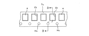
 キャリアテープTcは、図2に示すように、所定の幅で細長く形成され、長手方向に多数のキャビティCtを一定のピッチ間隔で配設しており、これらキャビティCtに、回路基板に実装される部品(電子部品)eがそれぞれ収納されている。キャビティCtの上部は開口されていて、キャリアテープTcの表面に貼り付けられたトップテープTt(図3参照)によって覆われている。 As shown in FIG. 2, the carrier tape Tc is formed in an elongated shape with a predetermined width, and a large number of cavities Ct are arranged at a constant pitch in the longitudinal direction. The carrier tape Tc is mounted on the circuit board in the cavities Ct. Each component (electronic component) e is accommodated. The upper part of the cavity Ct is opened and covered with a top tape Tt (see FIG. 3) attached to the surface of the carrier tape Tc.
 キャリアテープTcの幅方向の一端側には、送り穴HcがキャビティCtと同一のピッチ間隔、あるいはキャビティCtの2倍のピッチ間隔で形成され、これら送り穴HcはキャビティCtと一定の位置関係に配置されている。 On one end side in the width direction of the carrier tape Tc, feed holes Hc are formed at the same pitch interval as the cavity Ct or twice the pitch interval of the cavity Ct. These feed holes Hc are in a fixed positional relationship with the cavity Ct. Is arranged.
 テープフィーダ10には、リール12に巻回されたキャリアテープTcを定量ずつ送り出して、電子部品eをテープフィーダ10の先端部に設けられた部品供給位置17に1個ずつ供給する定量送り機構18が内蔵されている。定量送り機構18は、テープフィーダ10の本体に回転可能に支承され、キャリアテープTcの送り穴Hcに係合するスプロケット19と、スプロケット19を1ピッチ分ずつ回転させる図略のモータを備えている。 The tape feeder 10 feeds the carrier tape Tc wound around the reel 12 quantitatively, and feeds the electronic components e one by one to the component supply position 17 provided at the tip of the tape feeder 10. Is built-in. The fixed amount feeding mechanism 18 is rotatably supported by the main body of the tape feeder 10 and includes a sprocket 19 that engages with the feeding hole Hc of the carrier tape Tc and a motor (not shown) that rotates the sprocket 19 by one pitch. .
 なお、部品実装機に用いられるキャリアテープTcは、キャビティCtのピッチが互いに異なる複数種類からなり、キャリアテープTcの種類によって、キャビティCtのピッチ間隔およびキャビティCtと送り穴Hcの関係が定められている。従って、キャビティCtのピッチ間隔を画像処理等によって認識することにより、どの種類のキャリアテープTcであるかを把握することができ、それに基づいて、キャリアテープTcの送り穴Hcの位置を認識でき、後述するスプライシング時におけるキャリアテープTcの切断位置を決定できるようになる。 The carrier tape Tc used in the component mounter is composed of a plurality of types having different pitches of the cavities Ct. The pitch interval of the cavities Ct and the relationship between the cavities Ct and the feed holes Hc are determined depending on the type of the carrier tape Tc. Yes. Therefore, by recognizing the pitch interval of the cavity Ct by image processing or the like, it is possible to grasp which type of carrier tape Tc, and based on that, the position of the feed hole Hc of the carrier tape Tc can be recognized, The cutting position of the carrier tape Tc at the time of splicing described later can be determined.
 スプライシング装置20は、部品供給装置に装着されたテープフィーダ10に装着されている現リールに巻回されたキャリアテープの終端部を、交換する次リールに巻回されたキャリアテープの始端部に自動的に接続する装置である。 The splicing device 20 automatically sets the end portion of the carrier tape wound around the current reel attached to the tape feeder 10 attached to the component supply device to the beginning end portion of the carrier tape wound around the next reel to be replaced. Device to connect automatically.
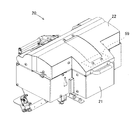
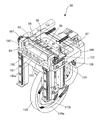
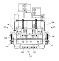
 スプライシング装置20は、図6に示すように、箱状の筺体21と、筐体21にピボット23(図24参照)を中心にして回動可能に支持され、筺体21の上面を開閉する蓋体22とを備え、図略の台車等に載置されて部品実装機の部品供給装置に装着されたテープフィーダ10間を移動可能に構成されている。蓋体22は、スプライシング時には閉じられ、スプライシング後のキャリアテープTcの取り出し時に開かれるようになっている。なお、蓋体22は、一旦閉止されると、後述するロック装置によって閉止状態を保持される。 As shown in FIG. 6, the splicing device 20 is supported by a box-shaped casing 21 and a casing 21 that is pivotable about a pivot 23 (see FIG. 24) and opens and closes the upper surface of the casing 21. 22, and is configured to be movable between tape feeders 10 mounted on a component supply device of a component mounter mounted on an unillustrated cart or the like. The lid 22 is closed at the time of splicing and is opened at the time of taking out the carrier tape Tc after the splicing. Note that once the lid 22 is closed, the lid 22 is held in a closed state by a lock device described later.
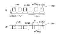
 スプライシング装置20によってスプライシングされる2つのキャリアテープTc(以下、第1キャリアテープT1、第2キャリアテープT2という)は、図4に示すように、同一部品種の第1部品e1(第2部品e2)が収容される第1キャビティCt1(第2キャビティCt2)が、所定ピッチPcで設けられている。 As shown in FIG. 4, two carrier tapes Tc (hereinafter referred to as a first carrier tape T1 and a second carrier tape T2) spliced by the splicing device 20 are the same as the first part e1 (second part e2). ) Are accommodated at a predetermined pitch Pc (second cavity Ct2).
 また、第1、第2キャリアテープT1,T2には、後述する第1テープ送り装置50(第2テープ送り装置51)の第1スプロケット61a(第2スプロケット61b)の歯67a(67b)と噛合可能な第1送り穴Hc1(第2送り穴Hc2)が、第1キャビティCt1(第2キャビティCt2)に平行に所定ピッチPhで穿孔されている。 In addition, the first and second carrier tapes T1 and T2 mesh with teeth 67a (67b) of a first sprocket 61a (second sprocket 61b) of a first tape feeder 50 (second tape feeder 51) described later. Possible first feed holes Hc1 (second feed holes Hc2) are bored at a predetermined pitch Ph in parallel with the first cavities Ct1 (second cavities Ct2).
 第1、第2キャリアテープT1,T2は、スプライシング装置20により任意の第1、第2切断箇所Q1,Q2を切断されて突き合わされ、後述するスプライシングテープ30によって接続される。第1切断箇所Q1(第2切断箇所Q2)としては、例えば、第1部品e1(第2部品e2)が有る第1キャビティCt1(第2キャビティCt2)と第1部品e1(第2部品e2)が無い空の第1キャビティCt1(第2キャビティCt2)との中間位置が選択される。 First and second carrier tapes T1 and T2 are spliced by splicing device 20 at arbitrary first and second cutting points Q1 and Q2, and connected by splicing tape 30 described later. As the first cutting point Q1 (second cutting point Q2), for example, a first cavity Ct1 (second cavity Ct2) having a first part e1 (second part e2) and a first part e1 (second part e2). An intermediate position with respect to the empty first cavity Ct1 (second cavity Ct2) having no gap is selected.
 切断後の空の第1キャビティCt1(第2キャビティCt2)が連なる第1キャリアテープT1(第2キャリアテープT2)が第1不要部分Tf1(第2不要部分Tf2)として廃棄される。なお、任意の数の空の第1キャビティCt1(第2キャビティCt2)を残すために、第1切断箇所Q1(第2切断箇所Q2)として隣り合う空の第1キャビティCt1(第2キャビティCt2)の中間位置も選択可能である。 The first carrier tape T1 (second carrier tape T2) in which the empty first cavities Ct1 (second cavities Ct2) after cutting are connected is discarded as the first unnecessary portion Tf1 (second unnecessary portion Tf2). In order to leave an arbitrary number of empty first cavities Ct1 (second cavities Ct2), adjacent empty first cavities Ct1 (second cavities Ct2) as first cutting points Q1 (second cutting points Q2) The intermediate position can also be selected.
 なお、キャリアテープT1、T2としては、キャビティCt1(Ct2)のピッチPcが異なったり、図5に示すように、キャビティ(エンボス部)Cte1(Cte2)が厚さ方向に突設されたエンボステープT1e(T2e)があり、これら種類の異なるキャリアテープも、スプライシング装置20で接続可能である。 As the carrier tapes T1 and T2, the pitch Cc of the cavities Ct1 (Ct2) is different, or as shown in FIG. 5, the embossed tape T1e having cavities (embossed portions) Cte1 (Cte2) projecting in the thickness direction. (T2e), and these different types of carrier tapes can also be connected by the splicing device 20.
 スプライシング装置20には、図7の左右より、スプライシングすべき2つのキャリアテープT1、T2が送り込まれるとともに、それに直交する図7の上方向より、2つのキャリアテープT1、T2を接続するスプライシングテープ30を貼付した保護テープ31(図8参照)が送り込まれるようになっている。そして、図8に示すように、キャリアテープT1、T2と保護テープ31とが交差するスプライシング位置LSにおいて、2つのキャリアテープT1、T2の端部同士がスプライシングテープ30によって互いに接続されるようになっている。 Two carrier tapes T1 and T2 to be spliced are fed into the splicing device 20 from the left and right in FIG. 7, and a splicing tape 30 for connecting the two carrier tapes T1 and T2 from the upper direction in FIG. A protective tape 31 (see FIG. 8) to which is attached is sent. 8, at the splicing position LS where the carrier tapes T1, T2 and the protective tape 31 intersect, the ends of the two carrier tapes T1, T2 are connected to each other by the splicing tape 30. ing.
 なお、保護テープ31に貼付されたスプライシングテープ30は、キャリアテープT1、T2との接着面を上側にして、スプライシング位置LSに送り込まれ、このスプライシングテープ30の上方に2つのキャリアテープT1、T2が位置決めされるようになっている。 The splicing tape 30 affixed to the protective tape 31 is sent to the splicing position LS with the adhesive surfaces with the carrier tapes T1 and T2 facing upward, and the two carrier tapes T1 and T2 are located above the splicing tape 30. It is designed to be positioned.
 スプライシングテープ30は、図10に示すように、連続した保護テープ31の上面に、2つのキャリアテープT1、T2に跨ってその両面に接着される表面用と裏面用で1セットのスプライシングテープ30a、30bからなっている。すなわち、スプライシングテープ30は、2つのキャリアテープT1、T2の表面側に接合される表面用スプライシングテープ30aと、2つのキャリアテープT1、T2の裏面側に接合される裏面用スプライシングテープ30bを1セットとしたものである。 As shown in FIG. 10, the splicing tape 30 has a set of splicing tapes 30a on the upper surface of the continuous protective tape 31 and for the front surface and the back surface that are bonded to both surfaces across the two carrier tapes T1 and T2. 30b. That is, the splicing tape 30 is a set of a front splicing tape 30a bonded to the front surface side of the two carrier tapes T1 and T2 and a back surface splicing tape 30b bonded to the rear surface side of the two carrier tapes T1 and T2. It is what.
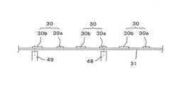
 表面用と裏面用で1セットのスプライシングテープ30は、保護テープ31の両サイドに一定のピッチ間隔で穿孔した送り穴31aと一定の位置関係を保ちながら、保護テープ31の長手方向に一定のピッチ間隔Pdを有して貼付されている。また、1セットのスプライシングテープ30a、30bは、表面用スプライシングテープ30aを先行側にして所定の間隔Pd1を有して配置され、かつ裏面用スプライシングテープ30bと後続する表面用スプライシングテープ30aが所定の間隔Pd2(Pd2=Pd-Pd1)を有して配置されている。そして、これら1セットのスプライシングテープ30a、30bには、後述する金属検知センサ48、49によって検知できるように、金属粉が埋設されている。 A set of splicing tapes 30 for the front surface and the back surface has a constant pitch in the longitudinal direction of the protective tape 31 while maintaining a fixed positional relationship with the feed holes 31a drilled at a constant pitch interval on both sides of the protective tape 31. Affixed with an interval Pd. The set of splicing tapes 30a and 30b is arranged with a predetermined interval Pd1 with the front splicing tape 30a leading and the rear splicing tape 30b and the front splicing tape 30a following the predetermined splicing tape 30a are predetermined. They are arranged with an interval Pd2 (Pd2 = Pd−Pd1). And in these 1 set of splicing tapes 30a and 30b, the metal powder is embed | buried so that it can detect with the metal detection sensors 48 and 49 mentioned later.
 図10および図11に示すように、保護テープ31の下方には、スプライシングテープ30a、30bを検知する2つの金属検知センサ48、49が所定の間隔を有して配置されている。具体的には、2つの金属検知センサ48、49は、表面用と裏面用で1セットのスプライシングテープ(1番目のスプライシングテープ)30がスプライシング位置LSに位置決めされたとき、それに後続する1セットのスプライシングテープ(2番目のスプライシングテープ)30のうちの表面用スプライシングテープ30aと、さらにそれに後続する1セットのスプライシングテープ(3番目のスプライシングテープ)のうちの裏面用スプライシングテープ30bとによって同時にオンされる位置に配置され、それ以外の状態(図13(B)~(E)参照)では、2つの金属検知センサ48、49が同時にオンされないようになっている。 As shown in FIGS. 10 and 11, below the protective tape 31, two metal detection sensors 48 and 49 for detecting the splicing tapes 30a and 30b are arranged with a predetermined interval. Specifically, the two metal detection sensors 48 and 49 are arranged so that when one set of splicing tape (first splicing tape) 30 is positioned at the splicing position LS for the front surface and the back surface, The surface splicing tape 30a of the splicing tape (second splicing tape) 30 and the back surface splicing tape 30b of one set of splicing tapes (third splicing tape) subsequent thereto are simultaneously turned on. In other states (see FIGS. 13B to 13E), the two metal detection sensors 48 and 49 are not turned on at the same time.
 スプライシングテープ30a、30bの上面は、2つのキャリアテープT1、T2に跨ってその両面に接着される粘着面をなし、この接着面に、図9に示すように、連続した紙台紙32が接着され、これら紙台紙32、スプライシングテープ30および保護テープ31の3層構造体が、供給リール33にロール状に巻回されている。 The upper surfaces of the splicing tapes 30a and 30b form an adhesive surface that is bonded to both sides of the two carrier tapes T1 and T2, and a continuous paper mount 32 is bonded to the bonded surface as shown in FIG. The three-layer structure of the paper mount 32, the splicing tape 30, and the protective tape 31 is wound around the supply reel 33 in a roll shape.
 保護テープ31の幅方向寸法は、紙台紙32の幅方向寸法より大きく、保護テープ31の幅方向の両端は紙台紙32の幅方向の両端より突出されている。一方、スプライシングテープ30の幅方向寸法は、紙台紙32の幅方向寸法と等しく、スプライシングテープ30は、送り用の穴31aの内側で表面用と裏面用で1セットとして、保護テープ31に貼付されている。 The width direction dimension of the protective tape 31 is larger than the width direction dimension of the paper mount 32, and both ends of the protective tape 31 in the width direction protrude from both ends of the paper mount 32 in the width direction. On the other hand, the width direction dimension of the splicing tape 30 is equal to the width direction dimension of the paper mount 32, and the splicing tape 30 is affixed to the protective tape 31 as one set for the front side and the back side inside the hole 31a for feeding. ing.
 保護テープ31には、図10に示すように、表面用スプライシングテープ30aに近接した位置に、キャリアテープT1、T2に形成された送り穴Hc1、Hc2と同じピッチ間隔に位置決め穴31bが保護テープ31の幅方向に沿って複数形成されている。また、裏面用スプライシングテープ30bには、キャリアテープT1、T2に形成された送り穴Hc1、Hc2と同じピッチ間隔に位置決め穴30b1が保護テープ31を貫いて保護テープ31の幅方向に沿って複数形成されている。 As shown in FIG. 10, the protective tape 31 has positioning holes 31b at the same pitch intervals as the feed holes Hc1 and Hc2 formed in the carrier tapes T1 and T2 at positions close to the surface splicing tape 30a. Are formed along the width direction. Further, a plurality of positioning holes 30b1 are formed in the back surface splicing tape 30b along the width direction of the protective tape 31 through the protective tape 31 at the same pitch intervals as the feed holes Hc1 and Hc2 formed in the carrier tapes T1 and T2. Has been.
 なお、保護テープ31に形成される送り用の穴31aや位置決め穴31bは、保護テープ31にスプライシングテープ30a、30bが所定位置に貼り付けられた後に、スプライシングテープ30bに位置決め穴30b1を形成するのに合わせてパンチングプレス等によって形成される。 The feed hole 31a and the positioning hole 31b formed in the protective tape 31 are formed by forming the positioning hole 30b1 in the splicing tape 30b after the splicing tapes 30a and 30b are attached to the protective tape 31 at predetermined positions. And is formed by a punching press or the like.
 スプライシング装置20には、図8に示すように、2つのキャリアテープT1、T2をスプライシングするスプライシング位置LSを横切る線上に、スプライシングテープ30を含む3層構造体をロール状に巻回した回転可能な供給リール33と、スプライシングテープ30より剥がされた紙台紙32を送り出す紙台紙送り装置35と、スプライシングテープ30が剥がされた保護テープ31を送り出す保護テープ送り装置36が配設されている。 As shown in FIG. 8, the splicing device 20 can be rotated by rolling a three-layer structure including the splicing tape 30 in a roll shape on a line crossing a splicing position LS for splicing the two carrier tapes T1 and T2. A supply reel 33, a paper board feeding device 35 that feeds the paper board 32 peeled off from the splicing tape 30, and a protective tape feeding device 36 that sends out the protective tape 31 from which the splicing tape 30 has been peeled off are provided.
 スプライシングテープ30の両面に接着される紙台紙32および保護テープ31との接着力は、保護テープ31に対する接着力の方が強く、スプライシングテープ30より紙台紙32を剥がしても、スプライシングテープ30が保護テープ31より剥がれることがないようにしている。 The adhesive strength between the paper mount 32 and the protective tape 31 bonded to both surfaces of the splicing tape 30 is stronger than the adhesive strength against the protective tape 31, and the splicing tape 30 is protected even if the paper mount 32 is peeled off from the splicing tape 30. The tape 31 is not peeled off.
 しかしながら、紙台紙32が剥がされたスプライシングテープ30の接着面に、キャリアテープT1、T2が接着されると、その粘着力は、保護テープ31に対する粘着力よりも強くなり、スプライシングテープ30より保護テープ31が容易に剥がれるようにしている。 However, when the carrier tapes T1 and T2 are adhered to the adhesive surface of the splicing tape 30 from which the paper mount 32 has been peeled off, the adhesive strength thereof becomes stronger than the adhesive strength against the protective tape 31, and the protective tape is more than the splicing tape 30. 31 is easily peeled off.
 紙台紙32、スプライシングテープ30および保護テープ31の3層構造体は、供給リール33に巻回された状態で、スプライシング装置20に装着され、先端を供給リール33より引き出される。そして、作業者によって紙台紙32が剥がされて折り返され、紙台紙32は紙台紙送り装置35によって送り出され、図略の紙台紙収納ボックスに廃棄される。 The three-layer structure of the paper mount 32, the splicing tape 30, and the protective tape 31 is mounted on the splicing device 20 while being wound around the supply reel 33, and the tip is pulled out from the supply reel 33. Then, the paper mount 32 is peeled off and folded by the operator, and the paper mount 32 is sent out by the paper mount feeder 35 and discarded in a paper mount storage box (not shown).
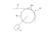
 紙台紙32が剥がされた保護テープ31、すなわち、スプライシングテープ30を接着面を上側にして多数貼付した保護テープ31は、スプライシング位置LSの中心を横切るようにして、後述する接合装置58を通って、先端部を保護テープ送り装置36の送り用スプロケット46(図12参照)に係合されるようになっている。 The protective tape 31 from which the paper mount 32 is peeled off, that is, the protective tape 31 to which a large number of splicing tapes 30 are attached with the adhesive surface facing upward passes through the joining device 58 described below so as to cross the center of the splicing position LS. The front end is engaged with the feed sprocket 46 of the protective tape feeder 36 (see FIG. 12).
 すなわち、送り用スプロケット46には、図12に示すように、保護テープ31に穿孔された送り穴31aのピッチと同一ピッチで複数の係合歯46aが円周方向に等角度間隔に形成され、送り用スプロケット46に連結されたステッピングモータ47を1ピッチ駆動することにより、係合歯46aに係合された保護テープ31が単位量送り出される。なお、ステッピングモータ47は、電源の投入により原点復帰されて、送り用スプロケット46の係合歯46aを常に頂点に位置するように位置決めするようになっている。 That is, as shown in FIG. 12, a plurality of engaging teeth 46a are formed on the feeding sprocket 46 at equal angular intervals in the circumferential direction at the same pitch as the pitch of the feeding holes 31a drilled in the protective tape 31, By driving the stepping motor 47 connected to the feed sprocket 46 by one pitch, the protective tape 31 engaged with the engagement teeth 46a is fed out by a unit amount. The stepping motor 47 is returned to the origin when the power is turned on, so that the engaging teeth 46a of the feed sprocket 46 are always positioned at the apex.
 ステッピングモータ47の1ピッチ駆動によって、保護テープ31(スプライシングテープ30)が図13(A)~(F)に示すように単位量ΔPdずつ送られ、これがN回(例えば、5回)繰り返されると、保護テープ31はスプライシングテープ30の1セットのピッチPd分だけ送られ、表面用と裏面用で1セットのスプライシングテープ30がスプライシング位置LSに順次搬送される。 When the stepping motor 47 is driven by 1 pitch, the protective tape 31 (splicing tape 30) is fed by the unit amount ΔPd as shown in FIGS. 13A to 13F, and this is repeated N times (for example, 5 times). The protective tape 31 is fed by the pitch Pd of one set of the splicing tape 30, and one set of the splicing tape 30 for the front surface and the back surface is sequentially conveyed to the splicing position LS.
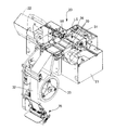
 図7に示すように、スプライシング装置20は、第1、第2テープ送り装置50,51と、第1、第2部品検知装置52,53と、第1、第2切断装置54,55と、第1、第2取込装置56,57と、接合装置58と、制御装置59(図6参照)とを備えている。第1、第2テープ送り装置50,51、第1、第2切断装置54,55、第1、第2取込装置56,57、接合装置58(一部を除く)および制御装置59は、筺体21および蓋体22の内部に収納され、配置されている。 As shown in FIG. 7, the splicing device 20 includes first and second tape feeders 50 and 51, first and second component detectors 52 and 53, first and second cutting devices 54 and 55, First and second take-in devices 56 and 57, a joining device 58, and a control device 59 (see FIG. 6) are provided. The first and second tape feeders 50 and 51, the first and second cutting devices 54 and 55, the first and second take-in devices 56 and 57, the joining device 58 (excluding a part) and the control device 59 are: The housing 21 and the lid 22 are housed and arranged.
 すなわち、図14に示すように、筺体21内および蓋体22内の両側に、第1、第2テープ送り装置50,51がそれぞれ配置され、第1、第2テープ送り装置50,51の間に、第1、第2切断装置54,55がそれぞれ配置されている。さらに、第1、第2切断装置54,55の間に、第1、第2取込装置56,57がそれぞれ配置され、第1、第2取込装置56,57の間に、接合装置58が配置されている。また、第1、第2部品検知装置52,53は、第1、第2テープ送り装置50,51の第1、第2搬送経路60a,60bの第1、第2検知位置Ld1,Ld2の上方に配置されている。 That is, as shown in FIG. 14, the first and second tape feeders 50 and 51 are disposed on both sides of the housing 21 and the lid body 22, respectively, and between the first and second tape feeders 50 and 51. In addition, first and second cutting devices 54 and 55 are arranged, respectively. Furthermore, the 1st, 2nd taking-in apparatus 56,57 is each arrange | positioned between the 1st, 2nd cutting device 54,55, and the joining apparatus 58 is interposed between the 1st, 2nd taking-in apparatus 56,57. Is arranged. The first and second component detection devices 52 and 53 are located above the first and second detection positions Ld1 and Ld2 of the first and second transport paths 60a and 60b of the first and second tape feeders 50 and 51, respectively. Is arranged.
 第1、第2テープ送り装置50,51は、筺体21両側面から中央に向かって水平方向に延在するように設けられた第1、第2搬送経路60a,60bと、第1、第2搬送経路60a,60bの下方に配置された第1、第2スプロケット61a,61bと、第1、第2スプロケット61a,61bに連接された第1、第2ステッピングモータ62a,62bと、第1、第2スプロケット61a,61bの近傍に配置された第1、第2スプロケット歯検知装置63a,63bと、第1、第2搬送経路60a,60bの上方に配置された第1、第2テープ検知装置64a,64b等とを備えている。 The first and second tape feeders 50 and 51 include first and second transport paths 60a and 60b provided so as to extend in the horizontal direction from both side surfaces of the housing 21 toward the center, and first and second. First and second sprockets 61a and 61b disposed below the transfer paths 60a and 60b, first and second stepping motors 62a and 62b connected to the first and second sprockets 61a and 61b, First and second sprocket tooth detecting devices 63a and 63b arranged in the vicinity of the second sprockets 61a and 61b, and first and second tape detecting devices arranged above the first and second conveying paths 60a and 60b. 64a, 64b and the like.
 第1、第2テープ送り装置50,51は、第1、第2キャリアテープT1,T2を第1、第2搬送経路60a,60bに沿って搬送して、第1、第2キャリアテープT1,T2の第1、第2切断箇所Q1,Q2(図4参照)を第1、第2切断位置Lc1,Lc2およびスプライシング位置LSに順次位置決め可能に構成されている。 The first and second tape feeders 50 and 51 convey the first and second carrier tapes T1 and T2 along the first and second conveyance paths 60a and 60b, respectively. The first and second cutting locations Q1 and Q2 (see FIG. 4) of T2 can be sequentially positioned at the first and second cutting positions Lc1 and Lc2 and the splicing position LS.
 第1、第2搬送経路60a,60bは、第1、第2キャリアテープT1,T2の幅より若干広い幅を有し、筺体21の両側面に設けられた第1、第2テープ入口84a,84bから第1、第2切断装置54,55の第1、第2カッター68a,68bによる第1、第2キャリアテープT1,T2の第1、第2切断位置Lc1,Lc2まで一直線に延びる溝状に形成されている。 The first and second transport paths 60a and 60b have widths slightly wider than the widths of the first and second carrier tapes T1 and T2, and the first and second tape inlets 84a, A groove extending in a straight line from 84b to the first and second cutting positions Lc1 and Lc2 of the first and second carrier tapes T1 and T2 by the first and second cutters 68a and 68b of the first and second cutting devices 54 and 55. Is formed.
 さらに、図7の拡大図A(第2搬送経路60bのみ示すが第1搬送経路60aも同様)に示すように、第1、第2搬送経路60a,60bには、第1、第2部品e1,e2が収納された第1、第2エンボステープT1e,T2eの第1、第2キャビティCte1,Cte2を通すための第1、第2細溝65a,65bが形成されている。 Furthermore, as shown in the enlarged view A of FIG. 7 (only the second transport path 60b is shown but the first transport path 60a is also the same), the first and second parts e1 are included in the first and second transport paths 60a and 60b. , E2 are formed with first and second narrow grooves 65a, 65b for passing the first and second cavities Cte1, Cte2 of the first and second embossed tapes T1e, T2e.
 すなわち、第1、第2細溝65a,65bにおける第1、第2切断位置Lc1,Lc2側には、第1、第2板ばね66a,66bが配置固定されている。第1、第2板ばね66a,66bは、凹形状に湾曲され、第1、第2切断位置Lc1,Lc2に向かうに従って斜め上方に傾斜するように配置固定されている。第1、第2板ばね66a,66bは、第1、第2エンボステープT1e,T2eの切断および搬送のときに作用する部材である。 That is, the first and second leaf springs 66a and 66b are arranged and fixed on the first and second cutting positions Lc1 and Lc2 side in the first and second narrow grooves 65a and 65b. The first and second leaf springs 66a and 66b are curved and arranged in a concave shape, and are arranged and fixed so as to incline obliquely upward toward the first and second cutting positions Lc1 and Lc2. The first and second leaf springs 66a and 66b are members that act when the first and second embossed tapes T1e and T2e are cut and transported.
 第1、第2スプロケット61a,61bには、第1、第2キャリアテープT1,T2に穿孔されている第1、第2送り穴Hc1,Hc2のピッチPhと同一ピッチの複数の第1、第2歯67a,67bが円周方向に形成されている。第1、第2スプロケット61a,61bは、第1、第2搬送経路60a,60bに沿って挿入されてくる第1、第2キャリアテープT1,T2の第1、第2送り穴Hc1,Hc2に噛合可能なように第1、第2搬送経路60a,60bの下方に配置されている。 The first and second sprockets 61a and 61b include a plurality of first and second sprockets having the same pitch as the pitch Ph of the first and second feed holes Hc1 and Hc2 drilled in the first and second carrier tapes T1 and T2. Two teeth 67a and 67b are formed in the circumferential direction. The first and second sprockets 61a and 61b are inserted into the first and second feed holes Hc1 and Hc2 of the first and second carrier tapes T1 and T2 inserted along the first and second transport paths 60a and 60b. It arrange | positions under the 1st, 2nd conveyance path | route 60a, 60b so that it can mesh | engage.
 第1、第2スプロケット歯検知装置63a,63bは、第1、第2スプロケット61a,61bが原位置になったことを、第1、第2スプロケット61a,61bの側面に付された第1、第2マークM1,M2を読み取ることにより検知する。 The first and second sprocket tooth detectors 63a and 63b are configured to indicate that the first and second sprockets 61a and 61b are in their original positions. Detection is performed by reading the second marks M1 and M2.
 第1、第2テープ検知装置64a,64bは、筺体21の両側面に設けられた第1、第2テープ入口84a,84bから第1、第2キャリアテープT1,T2が挿入されたことを検知する。 The first and second tape detectors 64a and 64b detect that the first and second carrier tapes T1 and T2 are inserted from the first and second tape inlets 84a and 84b provided on both side surfaces of the housing 21, respectively. To do.
 第1、第2部品検知装置52,53は、第1、第2搬送経路60a,60bを搬送される第1、第2キャリアテープT1,T2の第1、第2キャビティCt1、Ct2、第1、第2キャビティCt1,Ct2間のテープ部分および第1、第2キャビティCt1,Ct2内の第1、第2部品e1,e2を検知する。 The first and second component detectors 52 and 53 are the first and second cavities Ct1 and Ct2 of the first and second carrier tapes T1 and T2 that are transported through the first and second transport paths 60a and 60b. The tape portion between the second cavities Ct1 and Ct2 and the first and second parts e1 and e2 in the first and second cavities Ct1 and Ct2 are detected.
 図14および図15に示すように、第1、第2切断装置54,55は、第1、第2切断位置Lc1,Lc2に設けられた第1、第2カッター68a,68bと、第1、第2カッター68a,68bに摺接可能な第1、第2カム69a,69bと、第1、第2カム69a,69bに連接された第1、第2ギヤモータ70a,70bと、第1、第2カッター68a,68bに一端が取着され、蓋体22内に他端が取着された第1、第2カッターバネ71a,71bと、第1、第2カッター68a,68bに隣接して設けられた第1、第2押圧部材72a,72bと、第1、第2カッター68a,68bに一端が取着され、第1、第2押圧部材72a,72bに他端が取着された第1、第2押圧バネ73a,73bと、第1、第2カッター68a,68bの近傍に配置された第1、第2カッター検知装置74a,74b等とを備えている。 As shown in FIGS. 14 and 15, the first and second cutting devices 54 and 55 include first and second cutters 68a and 68b provided at the first and second cutting positions Lc1 and Lc2, First and second cams 69a and 69b slidably contactable with the second cutters 68a and 68b; first and second gear motors 70a and 70b connected to the first and second cams 69a and 69b; The first and second cutter springs 71a and 71b having one end attached to the two cutters 68a and 68b and the other end attached to the lid 22 are provided adjacent to the first and second cutters 68a and 68b. The first and second pressing members 72a and 72b and the first and second cutters 68a and 68b are attached at one end and the first and second pressing members 72a and 72b are attached at the other end. The second pressing springs 73a and 73b and the first and second cutters 68a First, second cutter detector 74a arranged in the vicinity of 68b, and a 74b or the like.
 第1、第2切断装置54,55は、第1、第2キャリアテープT1,T2の第1、第2切断箇所Q1,Q2において第1、第2不要部分Tf1,Tf2(図17参照)を切断可能に構成されている。 The first and second cutting devices 54 and 55 use the first and second unnecessary portions Tf1 and Tf2 (see FIG. 17) at the first and second cutting points Q1 and Q2 of the first and second carrier tapes T1 and T2. It is configured to be cuttable.
 第1、第2カッター68a,68bは、第1、第2切断位置Lc1,Lc2に位置決めされた第1、第2キャリアテープT1,T2の第1、第2切断箇所Q1,Q2を切断するために、上下方向に移動可能に装架され、第1、第2カム69a,69bの回転によって上下移動される。 The first and second cutters 68a and 68b cut the first and second cutting points Q1 and Q2 of the first and second carrier tapes T1 and T2 positioned at the first and second cutting positions Lc1 and Lc2. The first and second cams 69a and 69b are rotated up and down.
 第1、第2押圧部材72a,72bは、第1、第2切断位置Lc1,Lc2に位置決めされた第1、第2キャリアテープT1,T2の第1、第2切断箇所Q1,Q2の近傍を押圧して固定するために、上下方向に移動可能に設けられ、第1、第2押圧バネ73a,73bによって下方に付勢されている。 The first and second pressing members 72a and 72b are located near the first and second cutting locations Q1 and Q2 of the first and second carrier tapes T1 and T2 positioned at the first and second cutting positions Lc1 and Lc2. In order to press and fix, it is provided so as to be movable in the vertical direction, and is biased downward by the first and second pressing springs 73a and 73b.
 第1、第2取込装置56,57は、第1、第2切断位置Lc1,Lc2とスプライシング位置LSとの間に設けられ、第1、第2固定部材78a,78bに回動可能に支持された第1、第2取込部材75a,75bと、第1、第2取込部材75a,75bを回動する第1、第2取込部材回動装置76a,76b等とを備えて構成される。第1、第2取込装置56,57は、第1、第2キャリアテープT1,T2の切断された第1、第2不要部分Tf1,Tf2をそれぞれ取り込み可能に構成されている。 The first and second take-in devices 56 and 57 are provided between the first and second cutting positions Lc1 and Lc2 and the splicing position LS, and are rotatably supported by the first and second fixing members 78a and 78b. The first and second intake members 75a and 75b, and the first and second intake member rotating devices 76a and 76b for rotating the first and second intake members 75a and 75b are configured. Is done. The first and second take-in devices 56 and 57 are configured to take in the cut first and second unnecessary portions Tf1 and Tf2 of the first and second carrier tapes T1 and T2, respectively.
 第1、第2取込部材75a,75bには、第1、第2搬送経路60a,60b上を搬送される第1、第2キャリアテープT1,T2の第1、第2不要部分Tf1,Tf2を取り込むための第1、第2開口80a,80bと、第1、第2不要部分Tf1,Tf2を図略の廃却箇所に案内する第1、第2ダクト82a,82bが形成されている。 The first and second take-in members 75a and 75b have first and second unnecessary portions Tf1 and Tf2 of the first and second carrier tapes T1 and T2 conveyed on the first and second conveyance paths 60a and 60b. Are formed, and first and second ducts 82a and 82b for guiding the first and second unnecessary portions Tf1 and Tf2 to an unillustrated disposal location are formed.
 第1、第2取込部材75a,75bは、第1、第2不要部分Tf1,Tf2の取り込み時には、図15の1点鎖線で示す原位置に保持されている。また、第1、第2キャリアテープT1,T2をスプライシング位置Lsに搬送する場合には、図15の実線で示すように、第1、第2取込部材回動装置76a,76bにより所定角度回動され、第1、第2取込部材75a,75bに形成した第1、第2可動搬送経路79a,79bを第1、第2搬送経路60a,60bに整列させるようになっている。 The first and second take-in members 75a and 75b are held at the original positions indicated by the one-dot chain line in FIG. 15 when taking the first and second unnecessary portions Tf1 and Tf2. Further, when the first and second carrier tapes T1 and T2 are transported to the splicing position Ls, as shown by the solid lines in FIG. The first and second movable transport paths 79a and 79b formed on the first and second intake members 75a and 75b are aligned with the first and second transport paths 60a and 60b.
 接合装置58は、第1切断装置54と第2切断装置55との間に設けられている。接合装置58は、第1、第2搬送経路60a,60bの中間のスプライシング位置LSにおいて、第1、第2切断箇所Q1,Q2が突き合わされている第1、第2キャリアテープT1,T2をスプライシングテープ30によって接続可能に構成されている。 The joining device 58 is provided between the first cutting device 54 and the second cutting device 55. The joining device 58 splices the first and second carrier tapes T1 and T2 with which the first and second cutting points Q1 and Q2 are abutted at the splicing position LS between the first and second transport paths 60a and 60b. The tape 30 can be connected.
 次に、接合装置58の構成について、図19から図23に基づいて説明する。接合装置58は、第1昇降台91、押さえプレート97、第2昇降台101、旋回台103等を有している。第1昇降台91は、その脚部92を筐体21に昇降可能に案内支持されている。第1昇降台91上には、2つのキャリアテープT1、T2の接合位置(突合せ位置)を中心にして両側に、スプライシングテープ30bに形成された位置決め穴30b1および2つのキャリアテープT1、T2の各送り穴Hcに係合可能な各2つずつの第1位置決めピン93、94がキャリアテープT1、T2の送り方向に沿って突設されている。これら2組の第1位置決めピン93、94の各ピッチは、キャリアテープT1、T2の送り穴HcのピッチPの2倍に定められている。 Next, the configuration of the joining device 58 will be described with reference to FIGS. The joining device 58 includes a first elevator 91, a holding plate 97, a second elevator 101, a swivel 103, and the like. The first lift 91 is guided and supported by the casing 21 so that the legs 92 can be raised and lowered. On the first lifting platform 91, the positioning holes 30b1 formed in the splicing tape 30b and the two carrier tapes T1 and T2 are arranged on both sides centering on the joining position (butting position) of the two carrier tapes T1 and T2. Two first positioning pins 93, 94 each engaging with the feed hole Hc are provided so as to project along the feed direction of the carrier tapes T1, T2. Each pitch of these two sets of first positioning pins 93 and 94 is determined to be twice the pitch P of the feed holes Hc of the carrier tapes T1 and T2.
 また、第1昇降台91には、第1位置決めピン93、94の各間に、ピン穴95が形成されており、これらピン穴95に後述する旋回台103側の第2位置決めピン105が突入可能となっている。 In addition, pin holes 95 are formed between the first positioning pins 93 and 94 in the first lifting platform 91, and second positioning pins 105 on the swivel base 103 side which will be described later enter into these pin holes 95. It is possible.
 また、筐体21には、キャリアテープT1、T2の長手方向と直交する水平方向に、可動台96が移動可能に案内支持され、この可動台96に、第1位置決めピン93、94の上方位置において、押さえプレート97が取付けられている。押さえプレート97の先端には、第1位置決めピン93、94を収容できるU字形状の溝98が形成され、押さえプレート97は、溝98が第1位置決めピン93、94より離脱する後退端と、溝98が第1位置決めピン93、94を収容する前進端位置との間で進退できるようになっている。 In addition, a movable table 96 is guided and supported by the housing 21 in a horizontal direction orthogonal to the longitudinal direction of the carrier tapes T1 and T2, and the movable table 96 is positioned above the first positioning pins 93 and 94. The presser plate 97 is attached. A U-shaped groove 98 that can accommodate the first positioning pins 93 and 94 is formed at the tip of the pressing plate 97, and the pressing plate 97 has a retracted end from which the groove 98 is separated from the first positioning pins 93 and 94, The groove 98 can be moved forward and backward from the forward end position in which the first positioning pins 93 and 94 are accommodated.
 さらに、筐体21には、第2昇降台101の脚部102が昇降可能に案内支持されている。第2昇降台101上には、旋回台103がキャリアテープT1、T2の長手方向に平行なピボット軸104を旋回中心にして180度旋回可能に両端支持されている。旋回台103には、旋回中心よりオフセットした位置に押圧板103aが設けられ、この押圧板103aに複数の第2位置決めピン105とピン穴106が設けられている。第2位置決めピン105は、上記した第1昇降台91に設けた第1位置決めピン93、94の各間に対応する位置に配列され、第1昇降台91に設けたピン穴95に突入可能となっている。また、ピン穴106は、第2位置決めピン105の各間に対応する位置に配列され、第1昇降台91に設けた第1位置決めピン93、94が突入可能となっている。 Furthermore, the leg part 102 of the 2nd lifting platform 101 is supported by the housing | casing 21 so that raising / lowering is possible. On the second elevator 101, a swivel 103 is supported at both ends so that it can turn 180 degrees around a pivot shaft 104 parallel to the longitudinal direction of the carrier tapes T1 and T2. The swivel base 103 is provided with a pressing plate 103a at a position offset from the turning center, and a plurality of second positioning pins 105 and pin holes 106 are provided on the pressing plate 103a. The second positioning pins 105 are arranged at corresponding positions between the first positioning pins 93 and 94 provided on the first lifting platform 91 and can enter the pin holes 95 provided on the first lifting platform 91. It has become. The pin holes 106 are arranged at corresponding positions between the second positioning pins 105, and the first positioning pins 93 and 94 provided on the first lifting platform 91 can enter.
 第2位置決めピン105は、旋回台103の180度旋回によって、スプライシング位置LSに位置決めされた2つのキャリアテープT1、T2の送り穴Hcおよびスプライシングテープ30bの位置決め穴30b1に係合され、2つのキャリアテープT1、T2とこれを接続するスプライシングテープ30の三者の位置関係を一定に保つようになっている。 The second positioning pin 105 is engaged with the two carrier tapes T1 and T2 that are positioned at the splicing position LS and the positioning hole 30b1 of the splicing tape 30b by being rotated by 180 degrees of the swivel base 103, and the two carriers. The positional relationship between the three of the tapes T1 and T2 and the splicing tape 30 connecting the tapes T1 and T2 is kept constant.
 旋回台103のピボット軸104には、ピニオン107が取付けられ、このピニオン107に噛合うラック108がキャリアテープT1、T2の搬送方向と直交する水平方向に移動可能な可動台109に取付けられている。これにより、可動台109が移動されると、ピニオン107とラック108からなるラックピニオン機構により、旋回台103が旋回されるようになっている。 A pinion 107 is attached to the pivot shaft 104 of the swivel base 103, and a rack 108 that meshes with the pinion 107 is attached to a movable base 109 that is movable in a horizontal direction perpendicular to the conveying direction of the carrier tapes T1 and T2. . As a result, when the movable table 109 is moved, the swivel base 103 is swung by a rack and pinion mechanism including the pinion 107 and the rack 108.
 かかる旋回台103の旋回により、押圧板103aと第1昇降台91との間で、2つのキャリアテープT1、T2およびスプライシングテープ30の三者が挟持され、互いに接続されるようになっている。 By turning the swivel base 103, the three carrier tapes T1 and T2 and the splicing tape 30 are sandwiched between the pressing plate 103a and the first lift base 91 and are connected to each other.
 第1昇降台91および押圧板103aには、図19および図26に示すように、弾力に富むゴムシート121、122がそれぞれ取付けられている。これらゴムシート121、122は、スプライシングするキャリアテープの種類が紙テープであるか、エンボステープであるかに拘らず、スプライシングテープ30によってキャリアテープを的確にスプライシングするために設けたものである。 As shown in FIG. 19 and FIG. 26, elastic rubber sheets 121 and 122 are attached to the first elevator 91 and the pressing plate 103a, respectively. These rubber sheets 121 and 122 are provided for accurately splicing the carrier tape with the splicing tape 30 regardless of whether the carrier tape to be spliced is a paper tape or an embossed tape.
 すなわち、第1昇降台91上に取付けられたゴムシート121は、キャリアテープT1、T2の送り穴Hc1、Hc2が設けられた側に対してキャビティCt1、Ct2が設けられた側を低くした段差121aが形成され、これとは逆に、押圧板103a上に取付けられたゴムシート122は、図26(B)に示すように、送り穴Hc1、Hc2が設けられた側に対してキャビティCt1、Ct2が設けられた側を高くした段差122aが形成されている。そして、両ゴムシート121、122の段差の量d1、d2は、図26(A)に示すように、押圧板103aに取付けたゴムシート122のほうがより大きくしてある(d1<d2)。 That is, the rubber sheet 121 mounted on the first lifting platform 91 has a step 121a in which the side where the cavities Ct1 and Ct2 are provided is lower than the side where the feed holes Hc1 and Hc2 of the carrier tapes T1 and T2 are provided. Contrary to this, the rubber sheet 122 attached on the pressing plate 103a has cavities Ct1, Ct2 with respect to the side where the feed holes Hc1, Hc2 are provided, as shown in FIG. A step 122a is formed with the height of the side provided with. Further, as shown in FIG. 26A, the rubber sheet 122 attached to the pressing plate 103a has a larger level difference d1, d2 between the rubber sheets 121, 122 (d1 <d2).
 これは、紙テープが表面および裏面共に平面であるのに対して、エンボステープは表面は平面であるが、裏面はキャビティCt1、Ct2が突出されて凹凸となっており、この凹凸面にもスプライシングテープ30を確実に接着できるようにするためである。 This is because the paper tape is flat on both the front and back surfaces, whereas the embossed tape is flat on the front surface, but the back surface has cavities Ct1 and Ct2 protruding to form irregularities. This is to ensure that 30 can be bonded.
 これにより、後述するように、第1昇降台91と押圧板103aの各ゴムシート121、122間に紙テープからなるキャリアテープT1、T2が挟持される場合には、ゴムテープの段差高部が弾性変形されて、キャリアテープT1、T2にスプライシングテープ30が接合される。これに対して、第1昇降台91と押圧板103aの各ゴムシート間にエンボステープからなるキャリアテープT1、T2が挟持される場合には、第1昇降台91上のゴムシート121の段差低部にキャビティCt1、Ct2を収容できるため、キャビティCt1、Ct2に過度の圧力を加えることなく、スプライシングテープ30を接合できる。しかも、両ゴムシート121、122の段差を、押圧板103aに取付けられたゴムシート122のほうをより大きくしてあるため、エンボステープをスプライシングする場合に、キャビティCt1、Ct2をより大きな弾性力(圧縮しろ)で挟持して、キャビティCt1、Ct2に裏面用スプライシングテープを確実に接合できるようにしている。 Thus, as will be described later, when the carrier tapes T1 and T2 made of paper tape are sandwiched between the rubber sheets 121 and 122 of the first elevator 91 and the pressing plate 103a, the step height portion of the rubber tape is elastically deformed. Then, the splicing tape 30 is joined to the carrier tapes T1 and T2. On the other hand, when carrier tapes T1 and T2 made of embossed tape are sandwiched between the rubber sheets of the first elevator 91 and the pressing plate 103a, the level difference of the rubber sheet 121 on the first elevator 91 is low. Since the cavities Ct1 and Ct2 can be accommodated in the part, the splicing tape 30 can be joined without applying excessive pressure to the cavities Ct1 and Ct2. Moreover, since the step between the rubber sheets 121 and 122 is made larger in the rubber sheet 122 attached to the pressing plate 103a, the cavity Ct1 and Ct2 can be made to have a larger elastic force (when splicing the embossed tape). The back surface splicing tape can be reliably joined to the cavities Ct1 and Ct2.
 筐体21には、カムドラム110が旋回台103の旋回中心と平行な軸線の回りに回転可能に支持され、図略の駆動モータによって一定方向に低速回転されるようになっている。カムドラム110の両面には、内外2つずつのカム溝110a、110b、110c、110dがそれぞれ円周方向に無端状に形成されている。 The cam drum 110 is supported on the casing 21 so as to be rotatable about an axis parallel to the turning center of the swivel base 103, and is rotated at a low speed in a fixed direction by a drive motor (not shown). Two cam grooves 110 a, 110 b, 110 c, and 110 d are formed on both surfaces of the cam drum 110 so as to be endless in the circumferential direction.
 第1カム溝110aには、第1昇降台91の脚部92に軸支された図略の第1フォロアローラが係合されている。第2カム溝110bには、押さえプレート97に連結された可動台96に軸支された図略の第2フォロアローラが係合されている。第3カム溝110cには、第2昇降台101の脚部102に軸支された図略の第3フォロアローラが係合されている。第4カム溝110dには、可動台109に連結された連結部材112に軸支された図略の第4フォロアローラが係合されている。 The first cam groove 110a is engaged with a first follower roller (not shown) that is pivotally supported by the leg portion 92 of the first lifting platform 91. A second follower roller (not shown) that is pivotally supported by a movable base 96 connected to the pressing plate 97 is engaged with the second cam groove 110b. A third follower roller (not shown) that is pivotally supported by the leg portion 102 of the second lifting platform 101 is engaged with the third cam groove 110c. A fourth follower roller (not shown) that is pivotally supported by a connecting member 112 that is connected to the movable base 109 is engaged with the fourth cam groove 110d.
 これにより、カムドラム110が回転されると、第1~第4カム溝110a~110dにそれぞれ係合する第1~第4フォロアローラを介して、第1および第2昇降台91、101の各昇降運動、押さえプレート97の進退運動、ならびに旋回台103の旋回運動が連動して行われるようになっており、カムドラム110の1回転で、第1および第2昇降台91、101、押さえプレート97および旋回台103は、原位置に復帰されるようになっている。 As a result, when the cam drum 110 is rotated, the first and second lifting platforms 91 and 101 are moved up and down via the first to fourth follower rollers engaged with the first to fourth cam grooves 110a to 110d, respectively. The movement, the reciprocating movement of the holding plate 97, and the turning movement of the swivel base 103 are performed in conjunction with each other. With one rotation of the cam drum 110, the first and second lifting platforms 91 and 101, the press plate 97 and The swivel base 103 is returned to its original position.
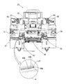
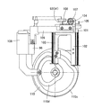
 スプライシング装置20には、図24に示すように、スプライシング動作中に蓋体22を閉止状態にロックするロック装置24が設けられている。ロック装置24は、筐体21に設置され、作動ロッド25aを上下方向に作動可能なソレノイド25と、筐体21にピボット26を中心にして回動可能に支持され、ソレノイド25によって回動されるフック27と、蓋体22に下方に突出するように設けられ、フック27に係脱可能に係合する係合ピン28とによって、主に構成されている。 As shown in FIG. 24, the splicing device 20 is provided with a lock device 24 that locks the lid 22 in the closed state during the splicing operation. The locking device 24 is installed in the casing 21 and is supported by the casing 21 so as to be rotatable about the pivot 26 and is rotated by the solenoid 25. The hook 27 and the engaging pin 28 that is provided so as to protrude downward from the lid body 22 and engage with the hook 27 so as to be detachable are mainly configured.
 筐体21と蓋体22との間には、蓋体22を開放方向に付勢する開放用スプリング29が設けられ、フック27と係合ピン28との係合が解除されると、蓋体22は開放用スプリング29によって自動的に開放されるようになっている。また、図示してないが、蓋体22にはドッグが設けられ、このドッグによって動作される閉止確認用センサが筐体21に設けられている。閉止確認用センサは蓋体22の閉止時にドッグによって動作され、閉止確認用センサのオン信号に基づいて蓋体22が閉止されたことが確認される。 An opening spring 29 that biases the lid 22 in the opening direction is provided between the housing 21 and the lid 22, and when the engagement between the hook 27 and the engagement pin 28 is released, the lid 22 is automatically opened by an opening spring 29. Although not shown, the lid 22 is provided with a dog, and a closing confirmation sensor operated by the dog is provided in the casing 21. The closing confirmation sensor is operated by a dog when the lid body 22 is closed, and it is confirmed that the lid body 22 is closed based on an ON signal of the closing confirmation sensor.
 そして、作業者によって蓋体22が閉止され、ドッグによって閉止確認用センサがオンされると、そのオン信号に基づいて、ソレノイド25の作動ロッド25aが図23の上方向に作動され、フック27が回動されて係合ピン28に係合される。これにより、ロック装置24によって蓋体22が閉止状態にロックされる。 Then, when the lid 22 is closed by the operator and the closing confirmation sensor is turned on by the dog, the operating rod 25a of the solenoid 25 is actuated upward in FIG. It is rotated and engaged with the engagement pin 28. Thereby, the lid 22 is locked in the closed state by the locking device 24.
 なお、2つのキャリアテープT1、T2がスプライシングテープ30によって互いに接続され、制御装置59より接続完了信号が発せられると、ソレノイド25の作動ロッド25aが図23の下方向に作動される。これにより、フック27が回動されて係合ピン28との係合が解除され、蓋体22は開放用スプリング29の付勢力によって自動的に開放される。 When the two carrier tapes T1 and T2 are connected to each other by the splicing tape 30 and a connection completion signal is issued from the control device 59, the actuating rod 25a of the solenoid 25 is actuated downward in FIG. As a result, the hook 27 is rotated to disengage from the engagement pin 28, and the lid 22 is automatically released by the urging force of the release spring 29.
 次に上記した実施の形態におけるスプライシング装置20の動作について説明する。テープフィーダ10に取付けたリール12に巻回された第1キャリアテープT1に保持された部品eの残量が少なくなると、第1キャリアテープT1の終端部に、同一種の部品eを収容した別のリールに巻回した第2キャリアテープT2の始端部をスプライシングテープ30によって接続するスプライシング処理が実施される。かかるスプライシングによって部品を補給し、テープフィーダ10からの部品の供給を継続して行えるようにしている。 Next, the operation of the splicing device 20 in the above embodiment will be described. When the remaining amount of the component e held on the first carrier tape T1 wound on the reel 12 attached to the tape feeder 10 decreases, another component e containing the same type of component e is accommodated at the terminal portion of the first carrier tape T1. Splicing processing is performed in which the start end portion of the second carrier tape T2 wound around the reel is connected by the splicing tape 30. Parts are supplied by such splicing so that the parts can be continuously supplied from the tape feeder 10.
 かかるスプライシングにおいては、通常正しい部品を収容したキャリアテープが接続されたかどうかをチェックする、いわゆるスプライシングベリファイが実行される。スプライシングベリファイは、旧リールに貼られたバーコードをバーコードリーダにより読み取り、旧リールに収容された部品のシリアルIDを管理コンピュータに送信する。次いで、新リールに貼られたバーコードをバーコードリーダにより読み取り、新リールに収容された部品のシリアルIDを管理コンピュータに送信する。 In such splicing, so-called splicing verification is performed in which it is usually checked whether a carrier tape containing correct components is connected. In splicing verification, the barcode attached to the old reel is read by a barcode reader, and the serial ID of the component accommodated in the old reel is transmitted to the management computer. Next, the barcode attached to the new reel is read by the barcode reader, and the serial ID of the component accommodated in the new reel is transmitted to the management computer.
 管理コンピュータのデータベースには、シリアルID毎に部品に関するデータが保存されているので、読み取ったシリアルIDより、2つのキャリアテープT1、T2に収容された部品が同じ種類のものであるか否かを照合できる。間違った部品であれば、照合エラーが操作パネルに表示されてオペレータに報知され、これに基づいてオペレータはスプライシングをやり直す。 Since the database of the management computer stores data regarding parts for each serial ID, it is determined whether the parts accommodated in the two carrier tapes T1 and T2 are of the same type based on the read serial ID. Can be verified. If the part is wrong, a collation error is displayed on the operation panel and notified to the operator, and based on this, the operator redoes splicing.
 このようなスプライシングベルファイが終了すると、2つのキャリアテープT1、T2の各端部をハサミによって切断する。この際、各キャリアテープT1、T2の端部には、通常、部品が収納されていない空のキャビティ部分が数十mm程度設けられているため、この部分を作業者によって切断する。この場合、切断面は、後述する説明から明らかなように、2つのキャリアテープT1、T2の合わせ面となるものではないので、特に正確性は要求されない。 When such splicing Belphi is completed, the ends of the two carrier tapes T1 and T2 are cut with scissors. At this time, an empty cavity portion in which no parts are accommodated is usually provided at the end of each of the carrier tapes T1 and T2, and this portion is cut by an operator. In this case, as will be apparent from the following description, the cut surface is not a mating surface between the two carrier tapes T1 and T2, so that no particular accuracy is required.
 通常、蓋体22は閉じられており、この状態で、作業者により電源がオンされると、制御装置59は、第1、第2スプロケット歯検知装置63a,63bからの検知信号に基づいて、ステッピングモータ62a、62bを原位置に復帰させる。その状態で、制御装置59は、第1、第2テープ検知装置64a、64bからの検知信号に基づいて、第1、第2テープ入口84a、84bから第1、第2テープT2の先端部が挿入されたか否かを検知する。第1、第2テープT2の先端部が挿入されたことが検知されると、ステッピングモータ62a、62bが起動され、第1、第2スプロケット61a、61bを回転するとともに、第1、第2取込部材75a、75bの可動部材77a、77bを上方向に移動させる。 Normally, the lid 22 is closed, and when the power is turned on by the operator in this state, the control device 59 is based on detection signals from the first and second sprocket tooth detection devices 63a and 63b. The stepping motors 62a and 62b are returned to their original positions. In this state, the control device 59 determines that the leading ends of the first and second tapes T2 from the first and second tape inlets 84a and 84b are based on the detection signals from the first and second tape detection devices 64a and 64b. Detects whether it has been inserted or not. When it is detected that the leading ends of the first and second tapes T2 are inserted, the stepping motors 62a and 62b are activated to rotate the first and second sprockets 61a and 61b, and to The movable members 77a and 77b of the insertion members 75a and 75b are moved upward.
 次いで、制御装置59は、第1、第2テープ検知装置64a、64bから検知信号に基づいて、第1、第2テープT1、T2の部品e1、e2が空の1番目のキャビティCt1、Ct2および2番目のキャビティCt1、Ct2を順次検出し、これら1番目および2番目のキャビティCt1、Ct2の検出に基づいて、キャビティCt1、Ct2間のピッチPcを演算する。 Next, based on the detection signals from the first and second tape detection devices 64a and 64b, the control device 59 first cavities Ct1 and Ct2 in which the components e1 and e2 of the first and second tapes T1 and T2 are empty and The second cavities Ct1 and Ct2 are sequentially detected, and the pitch Pc between the cavities Ct1 and Ct2 is calculated based on the detection of the first and second cavities Ct1 and Ct2.
 次いで、制御装置59は、キャビティCt1、Ct2間のピッチPcと、既知の検知位置Ld1、Ld2と切断位置Lc1、Lc2との間の距離D1、D2とから、第1、第2テープT1、T2の切断箇所Q1、Q2(図4参照)を演算する。そして、図16に示すように、第1、第2テープT1、T2を距離D1、D2移動させて不要部分Tf1、Tf2を第1、第2取込部材75a、75b内に取り込ませ、切断箇所Q1、Q2を切断位置Lc1、Lc2に搬送位置決めする。 Next, the controller 59 determines the first and second tapes T1, T2 from the pitch Pc between the cavities Ct1, Ct2 and the distances D1, D2 between the known detection positions Ld1, Ld2 and the cutting positions Lc1, Lc2. The cutting points Q1 and Q2 (see FIG. 4) are calculated. Then, as shown in FIG. 16, the first and second tapes T1 and T2 are moved by the distances D1 and D2, and the unnecessary portions Tf1 and Tf2 are taken into the first and second take-in members 75a and 75b. Q1 and Q2 are transported and positioned at the cutting positions Lc1 and Lc2.
 このようにして、第1および第2キャリアテープT1、T2の搬送位置決めが完了すると、制御装置59は、カッター68a,68bを押圧部材72a,72bとともにそれぞれ下降させ、押圧部材72a,72bによって、切断位置Lc1,Lc2に位置決めされた第1、第2キャリアテープT1,T2の切断箇所Q1,Q2の近傍を押圧して固定する。続いて、カッター68a,68bをそれぞれ下降させ、第1、第2キャリアテープT1,T2の切断箇所Q1,Q2をそれぞれ切断する。第1、第2キャリアテープT1,T2の切断された不要部分Tf1,Tf2は、取込部材75a、75bのダクト82a,82bに案内されて廃棄される。 When the transport positioning of the first and second carrier tapes T1 and T2 is completed in this way, the control device 59 lowers the cutters 68a and 68b together with the pressing members 72a and 72b, and cuts by the pressing members 72a and 72b. The vicinity of the cut portions Q1, Q2 of the first and second carrier tapes T1, T2 positioned at the positions Lc1, Lc2 is pressed and fixed. Subsequently, the cutters 68a and 68b are lowered to cut the cut portions Q1 and Q2 of the first and second carrier tapes T1 and T2, respectively. Unnecessary portions Tf1 and Tf2 of the first and second carrier tapes T1 and T2 are guided and discarded by the ducts 82a and 82b of the intake members 75a and 75b.
 カッター68a,68bによって第1、第2キャリアテープT1,T2が切断されると、制御装置59は、取込部材75a,75bを下方向に移動させる。しかる後、ステッピングモータ62a、62bによってスプロケット61a,61bをそれぞれ回転し、第1、第2キャリアテープT1,T2を、切断位置Lc1,Lc2とスプライシング位置LSとの間の既知の距離D3,D4だけそれぞれ移動させ、第1、第2キャリアテープT1,T2の切断箇所Q1,Q2をスプライシング位置LSに搬送位置決めする。これにより、第1、第2キャリアテープT1,T2の送り穴Hc1、Hc2がスプライシング位置LSに設けられた接合装置58の第1位置決めピン93、94に係合可能な位置に位置決めされる。 When the first and second carrier tapes T1 and T2 are cut by the cutters 68a and 68b, the control device 59 moves the intake members 75a and 75b downward. Thereafter, the sprockets 61a and 61b are rotated by the stepping motors 62a and 62b, respectively, and the first and second carrier tapes T1 and T2 are moved by the known distances D3 and D4 between the cutting positions Lc1 and Lc2 and the splicing position LS. Each of the first and second carrier tapes T1 and T2 is moved and positioned at the splicing position LS. Thereby, the feed holes Hc1 and Hc2 of the first and second carrier tapes T1 and T2 are positioned at positions where they can be engaged with the first positioning pins 93 and 94 of the joining device 58 provided at the splicing position LS.
 上記した第1、第2テープ送り装置50,51等により、第1および第2キャリアテープT1、T2を、第1および第2のキャリアテープT1、T2の各送り穴Hc1、Hc2に位置決めピン93,94が係合するスプライシング位置LSに位置決めする位置決め装置を構成している。 By the first and second tape feeders 50 and 51 and the like described above, the first and second carrier tapes T1 and T2 are positioned to the feed holes Hc1 and Hc2 of the first and second carrier tapes T1 and T2, respectively. , 94 is positioned at a splicing position LS that engages.
 これによって、第1、第2テープ入口84a,84bより挿入された第1および第2キャリアテープT1、T2の先端が、スプライシング位置LSにおいて、ピッチずれを生ずることなく位置決めされる。 Thus, the tips of the first and second carrier tapes T1 and T2 inserted from the first and second tape inlets 84a and 84b are positioned without causing a pitch shift at the splicing position LS.
 一方、供給リール33に巻回された紙台紙32、スプライシングテープ30および保護テープ31の3層構造体は、供給リール33より引き出され、紙台紙32が剥がされて紙台紙送り装置35により送り出される。スプライシングテープ30を貼付した保護テープ31は、保護テープ送り装置36により送り出され、表面用と裏面用で1セットのスプライシングテープ30がスプライシング位置LSに搬送される。 On the other hand, the three-layer structure of the paper mount 32, the splicing tape 30 and the protective tape 31 wound around the supply reel 33 is pulled out from the supply reel 33, and the paper mount 32 is peeled off and sent out by the paper mount feed device 35. . The protective tape 31 to which the splicing tape 30 is attached is sent out by the protective tape feeder 36, and one set of the splicing tape 30 for the front surface and the back surface is conveyed to the splicing position LS.
 すなわち、保護テープ送り装置36のステッピングモータ47によって、スプライシングテープ30が図13に示すように単位量ΔPdずつ送られ、これがN回(実施の形態においては、5回)繰り返されると、図13(F)に示すように、表面用と裏面用で1セットのスプライシングテープ30がピッチPd分だけ送られ、スプライシング位置LSに搬送される。 That is, the splicing tape 30 is fed by the unit amount ΔPd by the stepping motor 47 of the protective tape feeding device 36 as shown in FIG. 13, and when this is repeated N times (5 times in the embodiment), FIG. As shown in F), one set of splicing tape 30 for the front surface and the back surface is fed by the pitch Pd and conveyed to the splicing position LS.
 表面用と裏面用で1セットのスプライシングテープ30がスプライシング位置LSに搬送されると、それに後続する1セットのスプライシングテープ30の一方、すなわち、表面用スプライシングテープ30aが第1の金属検知センサ48によって検知され、同時に、さらに後続する1セットのスプライシングテープ30のうちの裏面用スプライシングテープ30bが第2の金属検知センサ49によって検知される。これにより、表面用と裏面用で1セットのスプライシングテープ30がスプライシング位置LSに正しく位置決めされたことが確認できるので、表面用スプライシングテープ30aおよび裏面用スプライシングテープ30bが逆配置でスプライシング位置LSに位置決めされるのを、確実に防止することができる。 When one set of the splicing tape 30 for the front surface and the back surface is conveyed to the splicing position LS, one of the subsequent set of splicing tapes 30, that is, the front splicing tape 30 a is moved by the first metal detection sensor 48. At the same time, the second metal detection sensor 49 detects the back surface splicing tape 30b of the set of splicing tapes 30 that follow. As a result, it is possible to confirm that one set of the splicing tape 30 for the front surface and the back surface is correctly positioned at the splicing position LS, so that the front splicing tape 30a and the back surface splicing tape 30b are reversely positioned at the splicing position LS. Can be surely prevented.
 このように、第1および第2の金属検知センサ48、49が同時にオンされるスプライシング位置にスプライシングテープ30が位置決めされると、裏面用スプライシングテープ30bに形成した位置決め穴30b1がスプライシング位置LSに設けられた接合装置58の第1位置決めピン93、94に係合可能な位置に位置決めされる(図25参照)。なお、スプライシングテープ30がスプライシング位置LSに位置決めされた際に、第1および第2キャリアテープT1、T2がスプライシング位置LSに未だ位置決めされていない場合には、その状態で、第1および第2キャリアテープT1、T2がスプライシング位置LSに位置決めされるまで待機する。 Thus, when the splicing tape 30 is positioned at the splicing position where the first and second metal detection sensors 48 and 49 are simultaneously turned on, the positioning hole 30b1 formed in the back surface splicing tape 30b is provided at the splicing position LS. It positions in the position which can be engaged with the 1st positioning pins 93 and 94 of the joined joining apparatus 58 (refer FIG. 25). When the first and second carrier tapes T1 and T2 are not yet positioned at the splicing position LS when the splicing tape 30 is positioned at the splicing position LS, the first and second carriers are in that state. Wait until the tapes T1 and T2 are positioned at the splicing position LS.
 第1および第2のキャリアテープT1、T2およびスプライシングテープ30がそれぞれスプライシング位置LSに位置決めされると、図略の駆動モータによってカムドラム110が回転される。カムドラム110の回転によって、まず、第1カム溝110aに係合する図略の第1フォロアローラを介して、第1昇降台91が上昇される。 When the first and second carrier tapes T1, T2 and the splicing tape 30 are positioned at the splicing position LS, the cam drum 110 is rotated by a drive motor (not shown). By the rotation of the cam drum 110, first, the first lifting platform 91 is lifted through a first follower roller (not shown) that engages with the first cam groove 110a.
 第1昇降台91の上昇により、第1位置決めピン93、94が、裏面用スプライシングテープ30bの位置決め穴30b1および2つのキャリアテープT1、T2の各送り穴Hcにそれぞれ係合される。この際、裏面用スプライシングテープ30bとキャリアテープT1、T2との間には、図26(A)に示すように、押さえプレート97が介在されているため、裏面用スプライシングテープ30bにキャリアテープT1、T2が接着することはない。これによって、2つのキャリアテープT1、T2とこれの裏面側に接着される裏面用スプライシングテープ30bの三者の位置関係が一定の関係に保たれる。 The first positioning pins 93 and 94 are engaged with the positioning holes 30b1 of the back surface splicing tape 30b and the feed holes Hc of the two carrier tapes T1 and T2 by the rising of the first lifting platform 91, respectively. At this time, as shown in FIG. 26 (A), a pressing plate 97 is interposed between the back surface splicing tape 30b and the carrier tapes T1 and T2, so that the carrier tape T1 and the back surface splicing tape 30b T2 does not adhere. Accordingly, the positional relationship between the three carrier tapes T1 and T2 and the back surface splicing tape 30b bonded to the back surface of the two carrier tapes T1 and T2 is kept constant.
 次いで、第2カム溝110bに係合する図略の第2フォロアローラを介して、可動台96が水平方向に移動され、裏面用スプライシングテープ30bとキャリアテープT1、T2との間に介在された押さえプレート97が、第1昇降台91に対して後退され、裏面用スプライシングテープ30bとキャリアテープT1、T2とが接着可能な状態となる。 Next, the movable base 96 is moved in the horizontal direction via a second follower roller (not shown) that engages with the second cam groove 110b, and is interposed between the back surface splicing tape 30b and the carrier tapes T1 and T2. The pressing plate 97 is retracted with respect to the first lifting platform 91, and the back surface splicing tape 30b and the carrier tapes T1 and T2 can be bonded.
 次いで、第3カム溝110cに係合する図略の第3フォロアローラを介して、可動台109が水平移動され、この可動台109の水平移動により、ラックピニオン機構(107、108)によって旋回台103が図22の時計回りに旋回される。かかる旋回台103の旋回により、図26(B)に示すように、第2位置決めピン105に係合された保護テープ31が折り曲げられ、表面用スプライシングテープ30aが、キャリアテープT1、T2の上方位置に接着面を下向きにして反転される。すなわち、保護テープ31は、キャリアテープT1、T2を挟み込むように折り曲げされ、キャリアテープT1、T2の裏面側に裏面用スプライシングテープ30bが、キャリアテープT1、T2の表面側に表面用スプライシングテープ30aが位置される。この際、保護テープ送り装置36のモータが逆回転されて、保護テープ31に弛みが与えられ、保護テープ31の折り曲げが許容される。 Next, the movable table 109 is horizontally moved through a third follower roller (not shown) that engages with the third cam groove 110c, and the movable table 109 is moved horizontally by the rack and pinion mechanism (107, 108). 103 is turned clockwise in FIG. As shown in FIG. 26 (B), the swivel base 103 is swung to bend the protective tape 31 engaged with the second positioning pin 105, and the surface splicing tape 30a is positioned above the carrier tapes T1 and T2. Inverted with the adhesive side facing down. That is, the protective tape 31 is bent so as to sandwich the carrier tapes T1 and T2, the back surface splicing tape 30b is provided on the back side of the carrier tapes T1 and T2, and the front splicing tape 30a is provided on the front side of the carrier tapes T1 and T2. Be positioned. At this time, the motor of the protective tape feeding device 36 is rotated in the reverse direction, the protective tape 31 is slackened, and the protective tape 31 is allowed to be bent.
 続いて、第4カム溝110dに係合する図略の第4フォロアローラを介して、第2昇降台101が下降される。第2昇降台101が下降されると、図26(C)に示すように、第2位置決めピン105が、保護テープ31の裏側から保護テープ31の位置決め穴31b、キャリアテープT1、T2の送り穴Hcおよび裏面用スプライシングテープ30bの位置決め穴30b1に係合される。 Subsequently, the second lifting platform 101 is lowered via a fourth follower roller (not shown) that engages with the fourth cam groove 110d. When the second elevator 101 is lowered, as shown in FIG. 26C, the second positioning pins 105 are moved from the back side of the protective tape 31 to the positioning holes 31b of the protective tape 31 and the feed holes of the carrier tapes T1 and T2. Hc is engaged with the positioning hole 30b1 of the back surface splicing tape 30b.
 さらに、第2昇降台101の下降により、キャリアテープT1、T2を挟持した状態で、折り曲げた保護テープ31が、旋回台103の押圧板103aと第1昇降台91との間で押付けられる。この押付けにより、保護テープ31に貼付された裏面用スプライシングテープ30bが、キャリアテープT1、T2の裏面に跨るように接着され、表面用スプライシングテープ30aが、キャリアテープT1、T2の表面に貼付された各トップテープTtに跨るように接着され、第1キャリアテープT1の終端部と第2キャリアテープT2の始端部が互いに接続される。かかる押付け状態は、一定時間(数秒間)持続される。 Furthermore, the bent protective tape 31 is pressed between the pressing plate 103a of the swivel base 103 and the first lift base 91 in a state where the carrier tapes T1 and T2 are sandwiched by the lowering of the second lift base 101. By this pressing, the back surface splicing tape 30b affixed to the protective tape 31 is adhered so as to straddle the back surfaces of the carrier tapes T1 and T2, and the front surface splicing tape 30a is affixed to the surfaces of the carrier tapes T1 and T2. Adhering so as to straddle each top tape Tt, the terminal end of the first carrier tape T1 and the start end of the second carrier tape T2 are connected to each other. This pressing state is maintained for a certain time (several seconds).
 この際、押圧板103aと第1昇降台91にはそれぞれ段差121a、122aを有するゴムシート121、122が設けられているが、上記した押付けにより、ゴムシート121、122はキャリアテープT1、T2の表面および裏面に倣って平坦状に弾性変形される。 At this time, the pressing plate 103a and the first lifting platform 91 are provided with rubber sheets 121 and 122 having steps 121a and 122a, respectively, but the rubber sheets 121 and 122 are formed on the carrier tapes T1 and T2 by the pressing described above. It is elastically deformed into a flat shape following the front and back surfaces.
 スプライシングテープ30による2つのキャリアテープT1、T2の接続は、キャリアテープT1、T2とスプライシングテープ30a、30bを、第1および第2位置決めピン93、94、105によって相対的なずれを拘束した状態で行われるので、2つのキャリアテープT1、T2をピッチずれを生ずることなく正確に接合できる。 The splicing tape 30 connects the two carrier tapes T1 and T2 with the carrier tapes T1 and T2 and the splicing tapes 30a and 30b being restrained from being displaced relative to each other by the first and second positioning pins 93, 94, and 105. As a result, the two carrier tapes T1 and T2 can be accurately joined without causing a pitch shift.
 上記したスプライシングテープ30による2つのキャリアテープT1、T2の接合は、カムドラム110のほぼ180度の回転によって達成され、残りの180度の回転によって、上記したと逆の動作で各構成部材が原位置に復帰される。 The joining of the two carrier tapes T1 and T2 by the splicing tape 30 described above is achieved by the rotation of the cam drum 110 by approximately 180 degrees, and the remaining 180 degrees of rotation causes the respective constituent members to be moved to their original positions in the reverse operation. Returned to
 すなわち、まず、第2昇降台101が上昇されて、旋回台103が第1昇降台91に対して上昇され、折り曲げた保護テープ31の押付けが解除されるとともに、第2位置決めピン105が裏面用スプライシングテープ30bの位置決め穴30b1および2つのキャリアテープT1、T2の各送り穴Hcより離脱される。この際、スプライシングテープ30のキャリアテープT1、T2に対する粘着性が高いため、保護テープ31の圧着の解除による保護テープ31のばね復帰力によって、保護テープ31はスプライシングテープ30より容易に剥離され、スプライシングテープ30がキャリアテープT1、T2より剥がれることはない。 That is, first, the second elevator 101 is raised, the swivel 103 is raised relative to the first elevator 91, the pressing of the bent protective tape 31 is released, and the second positioning pin 105 is used for the back surface. It is separated from the positioning hole 30b1 of the splicing tape 30b and the feed holes Hc of the two carrier tapes T1 and T2. At this time, since the adhesiveness of the splicing tape 30 to the carrier tapes T1 and T2 is high, the protective tape 31 is easily peeled off from the splicing tape 30 by the spring restoring force of the protective tape 31 by releasing the pressure-sensitive adhesive of the protective tape 31, so The tape 30 is not peeled off from the carrier tapes T1 and T2.
 続いて、ラックピニオン機構(108、107)を介して旋回台103が図21の反時計回りに旋回されるとともに、保護テープ送り装置36のモータが正回転されて、保護テープ31の弛みが除去される。 Subsequently, the swivel base 103 is swung counterclockwise in FIG. 21 via the rack and pinion mechanism (108, 107), and the motor of the protective tape feeder 36 is rotated forward to remove the slack of the protective tape 31. Is done.
 その後、押さえプレート97が前進されるとともに、第1昇降台91が下降され、第1位置決めピン93、94が裏面用スプライシングテープ30bの位置決め穴30b1および2つのキャリアテープT1、T2の各送り穴Hcより離脱される。一方、紙台紙送り装置35においてはモータが駆動されて、紙台紙32にテンションが与えられ、紙台紙32が必要な量だけ剥がされる。このようにして、第1のキャリアテープT1の終端部と第2のキャリアテープT2の始端部との接合が完了する。 Thereafter, the holding plate 97 is moved forward, the first lifting platform 91 is lowered, and the first positioning pins 93 and 94 are positioned on the positioning holes 30b1 of the back surface splicing tape 30b and the feed holes Hc of the two carrier tapes T1 and T2. More withdrawn. On the other hand, in the paper mount paper feeding device 35, a motor is driven to apply tension to the paper mount 32, and the paper mount 32 is peeled off by a necessary amount. In this way, the joining of the end portion of the first carrier tape T1 and the start end portion of the second carrier tape T2 is completed.
 このようにして、2つのキャリアテープT1、T2がスプライシングテープ30によって互いに接続されると、制御装置59より接続完了信号が発せられる。かかる接続完了信号に基づいて、スプライシング装置20のソレノイド25が作動されて作動ロッド25aが下方に移動され、フック27がピボット26を中心にして図24の時計回りに回動される。これにより、フック27と係合ピン28との係合が解除され、蓋体22はスプリング29の付勢力よりピボット23を中心にして回動され、自動的に開放される。その状態で、スプライシングした第1および第2キャリアテープT1、T2が、作業者によってスプライシング装置20より取り出される。 In this way, when the two carrier tapes T1 and T2 are connected to each other by the splicing tape 30, a connection completion signal is issued from the control device 59. Based on the connection completion signal, the solenoid 25 of the splicing device 20 is operated to move the operating rod 25a downward, and the hook 27 is rotated about the pivot 26 in the clockwise direction in FIG. As a result, the engagement between the hook 27 and the engagement pin 28 is released, and the lid 22 is rotated about the pivot 23 by the urging force of the spring 29 and automatically opened. In this state, the spliced first and second carrier tapes T1 and T2 are taken out from the splicing device 20 by the operator.
 その後、第2キャリアテープT2を巻回したリール12をテープフィーダ10にセットし、スプライシング処理を完了する。これによって、テープフィーダ10に部品が補給され、部品実装機においては、機械を停止させることなく、部品実装作業を継続して行えるようになる。 Thereafter, the reel 12 around which the second carrier tape T2 is wound is set on the tape feeder 10 to complete the splicing process. As a result, the parts are supplied to the tape feeder 10, and the component mounting machine can continue the component mounting operation without stopping the machine.
 なお、別のキャリアテープをスプライシングするために、蓋体22が作業者によって閉じられると、蓋体22に固定されたドッグによって図略の閉止確認用センサがオンされる。閉止確認用センサのオン信号に基づいて、ソレノイド25が作動され、作動ロッド25aが上方に移動される。これにより、フック27がピボット26を中心にして図24の反時計回りに回動され、蓋体22に固定された係合ピン28に係合する。同時に、フック27に取付けた図略のドッグによって図略の作動確認用センサがオンされる。これら閉止確認用センサおよび作動確認用センサが共にオンになると、スプライシング装置20の自動運転が可能となる。 Note that when the lid 22 is closed by an operator to splice another carrier tape, a closing confirmation sensor (not shown) is turned on by a dog fixed to the lid 22. Based on the ON signal of the closing confirmation sensor, the solenoid 25 is actuated and the actuating rod 25a is moved upward. As a result, the hook 27 is rotated counterclockwise in FIG. 24 about the pivot 26 and engaged with the engagement pin 28 fixed to the lid body 22. At the same time, an operation check sensor (not shown) is turned on by a dog (not shown) attached to the hook 27. When both the closing confirmation sensor and the operation confirmation sensor are turned on, the splicing apparatus 20 can be automatically operated.
 このように、蓋体22が閉じられると、外力によって蓋体22を開放することができなくなるため、自動運転中にスプライシング装置20内の動作部に作業者が接触することを防止でき、安全性を確保することができる。また、スプライシング作業が終了すると、蓋体22が自動的に開放されるので、作業性をアップすることができる。 As described above, when the lid body 22 is closed, the lid body 22 cannot be opened by an external force. Therefore, it is possible to prevent the operator from coming into contact with the operating portion in the splicing device 20 during automatic operation, and safety. Can be secured. Moreover, since the cover body 22 is automatically opened when the splicing work is completed, workability can be improved.
 なお、図示してないが、スプライシング装置20には非常停止時にロックを解除する操作ボタンが設けられ、スプライシング装置20の自動運転中に、操作ボタンを操作することにより、自動運転が停止され、蓋体22を手動で開放できるようになっている。この場合、蓋体22を閉めて再ロックしない限り、自動運転ができないようになっている。 Although not shown, the splicing device 20 is provided with an operation button for releasing the lock at the time of emergency stop, and the automatic operation is stopped by operating the operation button during the automatic operation of the splicing device 20, and the lid The body 22 can be opened manually. In this case, automatic operation cannot be performed unless the lid 22 is closed and re-locked.
 上記したように、ステッピングモータ47によって、スプライシングテープ30を図13に示すように単位量ΔPdずつN回送って、スプライシングテープ30を、第1および第2の金属検知センサ48、49が同時にオンされるスプライシング位置LSに位置決めし、接合装置58によって第1および第2キャリアテープT1、T2を自動的に接合する。 As described above, the splicing tape 30 is fed N times by the unit amount ΔPd as shown in FIG. 13 by the stepping motor 47, and the splicing tape 30 is turned on simultaneously with the first and second metal detection sensors 48 and 49. The first and second carrier tapes T1 and T2 are automatically joined by the joining device 58.
 なお、スプライシング装置20の蓋体22を閉止して電源を投入すると、ステッピングモータ47が原位置に復帰(送り用スプロケット46の係合歯46aが頂点に位置決め)され、しかる状態で、ステッピングモータ47によって、スプライシングテープ30を単位量ΔPdずつ間欠的に送られる。従って、スプライシング装置20の停止中にステッピングモータ47の位置がずれても、保護テープ31の先頭に貼付された最初のスプライシングテープ30を、第1および第2の金属検知センサ48、49が同時にオンされるスプライシング位置に正確に位置決めすることができる。 When the lid 22 of the splicing device 20 is closed and the power is turned on, the stepping motor 47 is returned to the original position (the engaging tooth 46a of the sprocket 46 for feeding is positioned at the apex), and in this state, the stepping motor 47 Thus, the splicing tape 30 is intermittently fed by the unit amount ΔPd. Therefore, even if the position of the stepping motor 47 is shifted while the splicing device 20 is stopped, the first and second metal detection sensors 48 and 49 are turned on at the same time for the first splicing tape 30 attached to the top of the protective tape 31. Can be accurately positioned at the splicing position.
 ところが、ステッピングモータ47によって、スプライシングテープ30を単位量ΔPdずつN回送っても、第1および第2の金属検知センサ48、49が同時にオンされない(第1の金属検知センサ48のみがオンする)場合には、スプライシングテープ切れ信号が制御装置59より発せられる。このように、第1および第2の金属検知センサ48、49によってスプライシングテープ30の切れを検知でき、作業者に新たな保護テープ31を準備するように促すことができる。 However, even if the splicing tape 30 is fed N times by the unit amount ΔPd by the stepping motor 47, the first and second metal detection sensors 48 and 49 are not simultaneously turned on (only the first metal detection sensor 48 is turned on). In this case, a splicing tape cut signal is issued from the control device 59. As described above, the first and second metal detection sensors 48 and 49 can detect the breakage of the splicing tape 30 and prompt the operator to prepare a new protective tape 31.
 そして、新たな保護テープ31をスプライシング装置20にセットした場合、ステッピングモータ47によって、スプライシングテープ30を単位量ΔPdずつ間欠的に送られることにより、第1および第2の金属検知センサ48、49が同時にオンされ、次に第1および第2の金属検知センサ48、49が同時にオンされたことに基づいて、保護テープ31に先頭に貼付された最初のスプライシングテープ30がスプライシング位置LSに位置決めあれたことを検知することができる。 When a new protective tape 31 is set in the splicing device 20, the splicing tape 30 is intermittently fed by the unit amount ΔPd by the stepping motor 47, whereby the first and second metal detection sensors 48, 49 are Based on the fact that the first and second metal detection sensors 48 and 49 are simultaneously turned on at the same time, the first splicing tape 30 affixed to the top of the protective tape 31 is positioned at the splicing position LS. Can be detected.
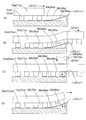
 上記した説明においては、表面および裏面が共に平面である紙テープからなる2つのキャリアテープT1、T2をスプライシングする例について述べたが、第1、第2キャリアテープT1,T2が、図5に示すようなエンボステープT1e,T2eの場合には、エンボステープT1e,T2eが、第1、第2搬送経路60a,60bに沿って搬送されるときは、図27(A)に示すように、第1、第2キャビティCte1,Cte2は、第1、第2細溝65a,65b内に沿って搬送される。そして、第1、第2エンボステープT1e,T2eが、第1、第2切断位置Lc1,Lc2に近付くと、第1、第2キャビティCte1,Cte2は、第1、第2板ばね66a,66bに乗り上げて第1、第2切断位置Lc1,Lc2を超え、第1、第2切断箇所Q1,Q2が第1、第2切断位置Lc1,Lc2に位置決めされる(図27(B)参照)。 In the above description, an example of splicing two carrier tapes T1 and T2 made of paper tape whose front and back surfaces are both flat has been described, but the first and second carrier tapes T1 and T2 are as shown in FIG. In the case of the embossed tapes T1e and T2e, when the embossed tapes T1e and T2e are transported along the first and second transport paths 60a and 60b, as shown in FIG. The second cavities Cte1 and Cte2 are transported along the first and second narrow grooves 65a and 65b. When the first and second embossed tapes T1e and T2e approach the first and second cutting positions Lc1 and Lc2, the first and second cavities Cte1 and Cte2 are moved to the first and second leaf springs 66a and 66b. It rides over the first and second cutting positions Lc1 and Lc2, and the first and second cutting positions Q1 and Q2 are positioned at the first and second cutting positions Lc1 and Lc2 (see FIG. 27B).
 そして、第1、第2カッター68a,68bが第1、第2押圧部材72a,72bとともにそれぞれ下降してくると、第1、第2押圧部材72a,72bが、第1、第2切断位置Lc1,Lc2に位置決めされた第1、第2エンボステープT1e,T2eの第1、第2切断箇所Q1,Q2の近傍を押圧して固定する。このとき、第1、第2キャビティCte1,Cte2は、第1、第2板ばね66a,66bを下方に弾性変形させて第1、第2細溝65a,65b内に収納される(図27(C)参照)。これにより、第1、第2エンボステープT1e,T2eの第1、第2切断箇所Q1,Q2は、第1、第2切断位置Lc1,Lc2に高精度に位置決めされるので、第1、第2エンボステープT1e,T2eの切断精度を高めることができる。 When the first and second cutters 68a and 68b are lowered together with the first and second pressing members 72a and 72b, the first and second pressing members 72a and 72b are moved to the first and second cutting positions Lc1. The first and second embossed tapes T1e and T2e positioned at Lc2 are pressed and fixed in the vicinity of the first and second cutting points Q1 and Q2. At this time, the first and second cavities Cte1 and Cte2 are housed in the first and second narrow grooves 65a and 65b by elastically deforming the first and second leaf springs 66a and 66b downward (FIG. 27 ( C)). As a result, the first and second cutting locations Q1 and Q2 of the first and second embossed tapes T1e and T2e are positioned with high precision at the first and second cutting positions Lc1 and Lc2, so the first and second The cutting accuracy of the embossed tapes T1e and T2e can be increased.
 そして、第1、第2カッター68a,68bが第1、第2押圧部材72a,72bとともにそれぞれ上昇すると、第1、第2板ばね66a,66bが復元して第1、第2切断位置Lc1,Lc2近傍の第1、第2キャビティCte1,Cte2を第1、第2細溝65a,65bより上方に持ち上げる(図27(D)参照)。これにより、第1、第2キャビティCte1,Cte2は、第1、第2板ばね66a,66bに乗り上げて第1、第2切断位置Lc1,Lc2を超えることができるので、第1、第2エンボステープT1e,T2eの搬送をスムーズに行うことができる。 When the first and second cutters 68a and 68b are lifted together with the first and second pressing members 72a and 72b, the first and second leaf springs 66a and 66b are restored and the first and second cutting positions Lc1, The first and second cavities Cte1 and Cte2 in the vicinity of Lc2 are lifted above the first and second narrow grooves 65a and 65b (see FIG. 27D). As a result, the first and second cavities Cte1 and Cte2 can ride on the first and second leaf springs 66a and 66b and exceed the first and second cutting positions Lc1 and Lc2. The tapes T1e and T2e can be smoothly transported.
 エンボステープT1e,T2eがスプライシング位置LSに位置決めされると、エンボステープT1e,T2eのキャビティCte1、Cte2が、第1昇降台91上に取付けたゴムシート121の段差低部に収容される。このため、キャビティCte1、Cte2に過度の力を加えることなく、ゴムシート121、122の弾性力によってエンボステープT1e,T2eの表面および裏面にスプライシングテープ30a、30bを接合することができる。 When the embossed tapes T1e and T2e are positioned at the splicing position LS, the cavities Cte1 and Cte2 of the embossed tapes T1e and T2e are accommodated in the low stepped portion of the rubber sheet 121 mounted on the first lifting platform 91. Therefore, the splicing tapes 30a and 30b can be joined to the front and back surfaces of the embossed tapes T1e and T2e by the elastic force of the rubber sheets 121 and 122 without applying excessive force to the cavities Cte1 and Cte2.
 しかも、第1昇降台91上に取付けたゴムシート121の段差と、押圧板103aに取付けたゴムシート122の段差に差を設けた(d1<d2)ことにより、エンボステープT1e,T2eがゴムシート121、122間に挟持される際に、送り穴Hc1、Hc2を設けた側よりもキャビティCte1、Cte2を設けた側がより大きな弾性力によって挟持されるようになる。これによって、エンボステープT1e,T2eのような凹凸のあるものでも、スプライシングテープ30を確実に接合することができるようになる。 In addition, a difference is provided between the step of the rubber sheet 121 attached on the first lifting platform 91 and the step of the rubber sheet 122 attached to the pressing plate 103a (d1 <d2), so that the embossed tapes T1e and T2e are rubber sheets. When sandwiched between 121 and 122, the side on which the cavities Cte1 and Cte2 are provided is sandwiched by a larger elastic force than the side on which the feed holes Hc1 and Hc2 are provided. As a result, the splicing tape 30 can be reliably joined even with unevenness such as the embossed tapes T1e and T2e.
 上記した実施の形態によれば、第1および第2キャリアテープT1、T2を互いに接近する方向に送って、第1および第2キャリアテープT1、T2の送り穴Hc1、Hc2に位置決めピン93、94が係合可能なスプライシング位置LSに位置決めする第1、第2テープ送り装置(位置決め装置)50、51と、スプライシング位置LSに、第1および第2キャリアテープT1、T2の送り方向と直交する方向に送られる連続した保護テープ31に貼付された金属が埋め込まれた表面用と裏面用で1セットの複数のスプライシングテープ30(30a、30b)と、保護テープ31の送り方向に間隔を有して配置され、スプライシングテープ30を検知する一対の金属検知センサ48、49と、スプライシング位置LSに送られたスプライシングテープ30a、30bを第1および第2キャリアテープT1、T2に跨ってその両面に接合する接合装置58とを有し、スプライシングテープ30a、30bは、保護テープ31の長手方向に間隔を有して規則的に配列され、1セットのスプライシングテープ30a、30bがスプライシング位置LSに位置決めされたときのみ、一対の金属検知センサ48、49が同時にオンされるように構成した。 According to the above-described embodiment, the first and second carrier tapes T1 and T2 are fed in directions approaching each other, and the positioning pins 93 and 94 are placed in the feed holes Hc1 and Hc2 of the first and second carrier tapes T1 and T2. The first and second tape feeding devices (positioning devices) 50 and 51 are positioned at the splicing position LS that can be engaged, and the splicing position LS is perpendicular to the feeding direction of the first and second carrier tapes T1 and T2. A set of a plurality of splicing tapes 30 (30a, 30b) for the front and back surfaces in which the metal affixed to the continuous protective tape 31 to be sent is embedded and spaced in the feed direction of the protective tape 31 A pair of metal detection sensors 48 and 49 that are arranged and detect the splicing tape 30 and a spatter sent to the splicing position LS A joining device 58 that joins the first and second carrier tapes T1 and T2 across the first and second carrier tapes T1 and T2, and the splicing tapes 30a and 30b have an interval in the longitudinal direction of the protective tape 31. The pair of metal detection sensors 48 and 49 are simultaneously turned on only when the one set of splicing tapes 30a and 30b is positioned at the splicing position LS.
 上記した構成により、一対の金属検知センサ48、49が同時にオンされることによって、表面用と裏面用で1セットのスプライシングテープ30a、30bがスプライシング位置LSに位置決めされたことを容易に検知することができる。これにより、表面用スプライシングテープ30aおよび裏面用スプライシングテープ30bが逆配置とならないようにスプライシングテープ30a、30bをスプライシング位置LSに正確に位置決めすることができるようになり、精度の高いスプライシングが可能なスプライシング装置20を実現することができる。 With the above-described configuration, when the pair of metal detection sensors 48 and 49 are simultaneously turned on, it is easily detected that one set of the splicing tapes 30a and 30b for the front surface and the back surface is positioned at the splicing position LS. Can do. As a result, the splicing tapes 30a and 30b can be accurately positioned at the splicing position LS so that the front splicing tape 30a and the back splicing tape 30b are not reversely arranged. The device 20 can be realized.
 また、上記した実施の形態によれば、保護テープ31の幅方向の両端に形成した送り出し用の穴31aに係合するスプロケット46の回転によって保護テープ31を単位量ずつN回送ることにより、表面用と裏面用のスプライシングテープ30a、30bが一対の金属検知センサ48、49によって同時にオンされる位置に位置決めされるようになっているので、スプロケット46の回転量に基づいて保護テープ31の送り精度を高めることができ、保護テープ31の伸び等に拘らず、スプライシングテープ30a、30bをスプライシング位置LSに正確に位置決めすることができる。 Further, according to the embodiment described above, the protective tape 31 is fed N times by unit amount by rotating the sprocket 46 engaged with the feed holes 31a formed at both ends of the protective tape 31 in the width direction, Since the splicing tapes 30a and 30b for the front and rear surfaces are positioned to be turned on simultaneously by the pair of metal detection sensors 48 and 49, the feeding accuracy of the protective tape 31 based on the rotation amount of the sprocket 46 The splicing tapes 30a and 30b can be accurately positioned at the splicing position LS regardless of the extension of the protective tape 31 or the like.
 また、上記した実施の形態によれば、第1および第2キャリアテープT1、T2およびスプライシングテープ30a、30bを挟持して、スプライシングテープ30a、30bを第1および第2キャリアテープT1、T2の表面および裏面に接合する昇降台91および押圧板103aに、段差を有するゴムシート121、122を設けたので、第1および第2キャリアテープT1、T2が、エンボステープT1e,T2eのような凹凸を有するものであっても、エンボステープT1e,T2eのキャビティCte1、Cte2に過度の力を加えることなく、ゴムシート121の弾性力によってエンボステープT1e,T2eの表面および裏面にスプライシングテープ30a、30bを確実に接合することができるようになる。 Further, according to the above-described embodiment, the first and second carrier tapes T1, T2 and the splicing tapes 30a, 30b are sandwiched, and the splicing tapes 30a, 30b are attached to the surfaces of the first and second carrier tapes T1, T2. Since the elevator sheet 91 and the pressing plate 103a joined to the back surface are provided with the rubber sheets 121 and 122 having steps, the first and second carrier tapes T1 and T2 have irregularities such as the embossed tapes T1e and T2e. Even if it is a thing, without applying excessive force to the cavities Cte1 and Cte2 of the embossed tapes T1e and T2e, the splicing tapes 30a and 30b are securely attached to the front and back surfaces of the embossed tapes T1e and T2e by the elastic force of the rubber sheet 121. It becomes possible to join.
 しかも、第1および第2キャリアテープT1、T2が紙テープのように、表面および裏面が共に平面なものであっても、ゴムシート121、122が弾性変形するので、ゴムシート121、122に段差があっても何ら支障がない。 In addition, even if the first and second carrier tapes T1 and T2 are both flat, like the paper tape, since the rubber sheets 121 and 122 are elastically deformed, there is a step in the rubber sheets 121 and 122. There is no problem even if it exists.
 さらに、上記した実施の形態によれば、蓋体22をロック装置24によりロックして、外力によって蓋体22を開放することができないようにしたので、自動運転中にスプライシング装置20内の動作部に作業者が接触することを防止でき、安全性を確保することができる。また、スプライシング作業が終了すると、蓋体22を自動的に開放できるので、作業性をアップすることができる。 Furthermore, according to the above-described embodiment, the lid body 22 is locked by the locking device 24 so that the lid body 22 cannot be opened by an external force. It is possible to prevent the worker from coming into contact with the machine and to ensure safety. Moreover, since the cover body 22 can be automatically opened when the splicing work is completed, workability can be improved.
 上記した実施の形態においては、スプライシングテープ30a、30bに金属を埋め込み、金属検知センサ48、49によってスプライシングテープ30a、30bを検出する例について述べたが、金属検知以外の方法によってスプライシングテープを検出することも可能である。 In the above-described embodiment, an example has been described in which metal is embedded in the splicing tapes 30a and 30b, and the splicing tapes 30a and 30b are detected by the metal detection sensors 48 and 49. However, the splicing tape is detected by a method other than metal detection. It is also possible.
 上記した実施の形態においては、スプライシングテープ30、保護テープ31および紙台紙32の3層構造体について述べたが、紙台紙32をなくして、スプライシングテープ30と保護テープ31との2層構造とすることもできる。 In the above-described embodiment, the three-layer structure of the splicing tape 30, the protective tape 31, and the paper mount 32 has been described. However, the paper mount 32 is eliminated and a two-layer structure of the splicing tape 30 and the protective tape 31 is formed. You can also.
 また、第1および第2キャリアテープT1、T2をスプライシング位置LSに位置決めする位置決め装置(第1、第2テープ送り装置)50、51、スプライシングテープ30a、30bを貼付した保護テープ31を送る保護テープ送り装置36、ならびにスプライシング位置LSにおいてスプライシングテープ30a、30bを第1および第2キャリアテープT1、T2に接合する接合装置58等は、本発明の実施に好適な例示的な構成を示したものにすぎず、実施の形態で述べた構成に限定されるものではない。 Further, a protective tape for feeding a protective tape 31 to which positioning devices (first and second tape feeders) 50, 51 and splicing tapes 30a, 30b for positioning the first and second carrier tapes T1, T2 at the splicing position LS are provided. The feeding device 36 and the joining device 58 that joins the splicing tapes 30a and 30b to the first and second carrier tapes T1 and T2 at the splicing position LS show exemplary configurations suitable for implementing the present invention. However, it is not limited to the configuration described in the embodiment.
 斯様に、本発明は、特許請求の範囲に記載した本発明の主旨を逸脱しない範囲内で種々の形態を採り得るものである。 Thus, the present invention can take various forms without departing from the gist of the present invention described in the claims.
 20…スプライシング装置、21…筐体、22…蓋体、24…ロック装置、30(30a、30b)…スプライシングテープ、31…保護テープ、31a…送り出し用穴、36…保護テープ送り装置、46…スプロケット、47…ステッピングモータ、48、49…センサ(金属検知センサ)、50、51…位置決め装置(テープ送り装置)、58…接合装置、93、94、105…位置決めピン、T1、T2…キャリアテープ、Hc1、Hc2…送り穴、Ct1、Ct2…キャビティ、LS…スプライシング位置。 DESCRIPTION OF SYMBOLS 20 ... Splicing device, 21 ... Housing, 22 ... Lid, 24 ... Lock device, 30 (30a, 30b) ... Splicing tape, 31 ... Protection tape, 31a ... Delivery hole, 36 ... Protection tape feeder, 46 ... Sprocket, 47 ... Stepping motor, 48, 49 ... Sensor (metal detection sensor), 50, 51 ... Positioning device (tape feeding device), 58 ... Joining device, 93, 94, 105 ... Positioning pin, T1, T2 ... Carrier tape , Hc1, Hc2 ... feed hole, Ct1, Ct2 ... cavity, LS ... splicing position.

Claims (4)

  1.  一定の間隔に送り穴と部品収納用キャビティを設けた第1キャリアテープと第2キャリアテープとをスプライシングテープによって接続するスプライシング装置であって、
     前記第1および第2キャリアテープを互いに接近する方向に送って、前記第1および第2キャリアテープの前記送り穴に位置決めピンが係合可能なスプライシング位置に位置決めする位置決め装置と、
     前記スプライシング位置に、前記第1および第2キャリアテープの送り方向と直交する方向に送られる連続した保護テープに貼付され、前記キャリアテープの表面側を接続するための表面用と前記キャリアテープの裏面側を接続するための裏面用で1セットの複数のスプライシングテープと、
     前記保護テープの送り方向に間隔を有して配置され、前記スプライシングテープを検知する一対のセンサと、
     前記スプライシング位置に送られた前記スプライシングテープを前記第1および第2キャリアテープに跨ってその両面に接合する接合装置とを有し、
     前記スプライシングテープは、前記保護テープの長手方向に間隔を有して規則的に配列され、
     前記1セットのスプライシングテープが前記スプライシング位置に位置決めされたときのみ、前記一対のセンサが同時にオンされるように構成した、
    スプライシング装置。
    A splicing device for connecting a first carrier tape and a second carrier tape provided with feed holes and component storage cavities at regular intervals by a splicing tape,
    A positioning device that feeds the first and second carrier tapes in directions approaching each other and positions the splicing positions in which positioning pins can be engaged with the feed holes of the first and second carrier tapes;
    At the splicing position, affixed to a continuous protective tape that is fed in a direction orthogonal to the feeding direction of the first and second carrier tapes, and for the front side for connecting the front side of the carrier tape and the back side of the carrier tape A plurality of splicing tapes for the back side for connecting the sides,
    A pair of sensors that are arranged at intervals in the feeding direction of the protective tape and detect the splicing tape;
    A joining device that joins the splicing tape sent to the splicing position across the first and second carrier tapes on both sides thereof;
    The splicing tape is regularly arranged with an interval in the longitudinal direction of the protective tape,
    The pair of sensors are configured to be turned on simultaneously only when the one set of splicing tape is positioned at the splicing position.
    Splicing device.
  2.  前記スプライシングテープには、金属が埋め込まれ、前記センサは、前記金属を検知する金属検知センサからなっている請求項1に記載のスプライシング装置。 The splicing device according to claim 1, wherein a metal is embedded in the splicing tape, and the sensor includes a metal detection sensor that detects the metal.
  3.  前記保護テープの幅方向の両端には送り出し用の穴が形成され、該穴に係合するスプロケットの回転によって前記保護テープが単位量ずつN回送られることにより、前記1セットのスプライシングテープが前記一対のセンサによって同時にオンされる位置に位置決めされるようになっている請求項1または請求項2に記載のスプライシング装置。 Holes for feeding are formed at both ends in the width direction of the protective tape, and the protective tape is fed N times by a unit amount by the rotation of the sprocket engaged with the holes, so that the one set of splicing tape is the pair. The splicing device according to claim 1 or 2, wherein the splicing device is positioned at a position where the sensors are simultaneously turned on.
  4.  一定の間隔に送り穴と部品収納用キャビティを設けた第1キャリアテープと第2キャリアテープとをスプライシングテープによって接続するスプライシング装置に用いるスプライシングテープ検知方法であって、
     スプライシング位置に位置決めされた前記第1および第2キャリアテープに跨ってその両面に接着される表面用と裏面用で1セットのスプライシングテープを保護テープに貼付し、
     前記1セットのスプライシングテープが前記スプライシング位置に位置決めされたときのみ、前記保護テープの送り方向に間隔を有して配置した一対のセンサを、同時にオンするようにした、
    スプライシング装置に用いるスプライシングテープ検知方法。
    A splicing tape detection method for use in a splicing device that connects a first carrier tape and a second carrier tape provided with feed holes and component storage cavities at regular intervals by a splicing tape,
    A set of splicing tapes for the front surface and the back surface, which are bonded to both surfaces of the first and second carrier tapes positioned at the splicing position, are attached to a protective tape,
    Only when the one set of splicing tapes is positioned at the splicing position, a pair of sensors arranged at intervals in the feeding direction of the protective tape are turned on simultaneously.
    A splicing tape detection method used in a splicing device.
PCT/JP2012/083867 2012-12-27 2012-12-27 Splicing device and splicing-tape detection method WO2014102965A1 (en)

Priority Applications (8)

Application Number Priority Date Filing Date Title
JP2014553964A JP6067033B2 (en) 2012-12-27 2012-12-27 Splicing device and splicing tape detection method
CN201280078018.2A CN104885589B (en) 2012-12-27 2012-12-27 Attachment means and connect band detection method
PCT/JP2012/083867 WO2014102965A1 (en) 2012-12-27 2012-12-27 Splicing device and splicing-tape detection method
EP12890647.6A EP2941111B1 (en) 2012-12-27 2012-12-27 Splicing device and splicing-tape detection method
EP13867223.3A EP2941112B1 (en) 2012-12-27 2013-04-11 Splicing-tape feed device and feed method
PCT/JP2013/060974 WO2014103395A1 (en) 2012-12-27 2013-04-11 Splicing-tape feed device and feed method
CN201380068280.3A CN104904331B (en) 2012-12-27 2013-04-11 Connect band conveying device and carrying method
JP2014554172A JP6067034B2 (en) 2012-12-27 2013-04-11 Splicing tape feeder and feeding method

Applications Claiming Priority (1)

Application Number Priority Date Filing Date Title
PCT/JP2012/083867 WO2014102965A1 (en) 2012-12-27 2012-12-27 Splicing device and splicing-tape detection method

Publications (1)

Publication Number Publication Date
WO2014102965A1 true WO2014102965A1 (en) 2014-07-03

Family

ID=51020119

Family Applications (2)

Application Number Title Priority Date Filing Date
PCT/JP2012/083867 WO2014102965A1 (en) 2012-12-27 2012-12-27 Splicing device and splicing-tape detection method
PCT/JP2013/060974 WO2014103395A1 (en) 2012-12-27 2013-04-11 Splicing-tape feed device and feed method

Family Applications After (1)

Application Number Title Priority Date Filing Date
PCT/JP2013/060974 WO2014103395A1 (en) 2012-12-27 2013-04-11 Splicing-tape feed device and feed method

Country Status (4)

Country Link
EP (2) EP2941111B1 (en)
JP (2) JP6067033B2 (en)
CN (2) CN104885589B (en)
WO (2) WO2014102965A1 (en)

Cited By (5)

* Cited by examiner, † Cited by third party
Publication number Priority date Publication date Assignee Title
WO2018073924A1 (en) * 2016-10-20 2018-04-26 富士機械製造株式会社 Splicing device
WO2019142247A1 (en) * 2018-01-16 2019-07-25 株式会社Fuji Splicing device
KR20190114203A (en) * 2018-03-29 2019-10-10 유경천 Connection jig tape
US10881041B2 (en) * 2015-08-31 2020-12-29 Fuji Corporation Component mounting machine, feeder device, and splicing work defect determination method
CN113543624A (en) * 2021-07-06 2021-10-22 绍兴新辉照明有限公司 Automatic paster device of circuit board

Families Citing this family (13)

* Cited by examiner, † Cited by third party
Publication number Priority date Publication date Assignee Title
US10729047B2 (en) * 2015-03-31 2020-07-28 Fuji Corporation Automatic splicing device
JP6523438B2 (en) * 2015-04-28 2019-05-29 株式会社Fuji Splicing device and tape detection method used therefor
JP6492289B2 (en) * 2015-10-14 2019-04-03 パナソニックIpマネジメント株式会社 Component supply device and component mounting device
TWI640465B (en) * 2016-02-04 2018-11-11 萬潤科技股份有限公司 Electronic component packaging carrier tape guiding method and device
CN105850704B (en) * 2016-06-17 2021-12-17 江苏静园环艺建设工程有限公司 Floating bed device for aquatic plant cultivation
US10457512B2 (en) 2016-09-19 2019-10-29 New Era Converting Machinery, Inc. Automatic lapless butt material splice
CN106686907B (en) * 2017-01-22 2018-12-11 陈振富 Make the method and device of the accurate absorbing material of chip mounter
CN107031893B (en) * 2017-05-31 2020-02-21 深圳市宝尔威精密机械有限公司 General material machine that connects of SMD carrier band
WO2019087270A1 (en) 2017-10-31 2019-05-09 ヤマハ発動機株式会社 Component supply device and component mounting device
US11510350B2 (en) * 2017-12-06 2022-11-22 Yamaha Hatsudoki Kabushiki Kaisha Component mounter, component supply reel driving method
JP2021166225A (en) * 2020-04-06 2021-10-14 株式会社Fuji Carrier tape determination device
CN116209237B (en) * 2022-12-29 2023-10-27 东莞市富颖电子材料有限公司 Component dispensing paste and preparation process thereof
CN116828727B (en) * 2023-08-31 2023-12-05 四川英创力电子科技股份有限公司 Circuit board glue tearing device with width-adjustable structure and use method thereof

Citations (8)

* Cited by examiner, † Cited by third party
Publication number Priority date Publication date Assignee Title
JP2002207286A (en) * 2001-01-09 2002-07-26 Mitsui Mining & Smelting Co Ltd Method for aligning films joining device and gage member for the same as well as film joining device
JP2003031989A (en) * 2001-07-13 2003-01-31 Matsushita Electric Ind Co Ltd Connection jig and connection method of electronic component supply tape
JP2007335595A (en) 2006-06-14 2007-12-27 Fuji Mach Mfg Co Ltd Component feeding device equipped with splicing detector
JP2010087390A (en) * 2008-10-02 2010-04-15 Fuji Mach Mfg Co Ltd Device for splicing component supply tape
JP2011233600A (en) * 2010-04-23 2011-11-17 Panasonic Corp Jig and attachment method
JP2012169351A (en) * 2011-02-10 2012-09-06 Panasonic Corp Cutting device and cutting method
JP2012169352A (en) * 2011-02-10 2012-09-06 Panasonic Corp Jig, and connection method of tape
JP2012248592A (en) * 2011-05-26 2012-12-13 Panasonic Corp Carrier tape splicing jig and splicing method

Family Cites Families (10)

* Cited by examiner, † Cited by third party
Publication number Priority date Publication date Assignee Title
EP0613339A1 (en) * 1993-02-25 1994-08-31 Willi, A., Dipl.-Ing., Patentanwalt Method, apparatus and connexion strip to splice belts with covering tape
JP2000038242A (en) * 1998-07-24 2000-02-08 Katoo Seiko:Kk Connection method for taping of square hole punch carrier shape and tape for connection
JP3767488B2 (en) * 2002-02-06 2006-04-19 株式会社片岡機械製作所 Sheet winding device
US6817216B2 (en) * 2002-08-22 2004-11-16 Accu-Assembly Incorporated Electronic component placement
JP4170181B2 (en) * 2003-09-09 2008-10-22 リンテック株式会社 Belt-like body connection device and connection method
JP2007150145A (en) * 2005-11-30 2007-06-14 Juki Corp Parts feeder
JP2010120344A (en) * 2008-11-21 2010-06-03 Mitsui Mining & Smelting Co Ltd Film joined body, splicing tape for forming the same, and method for joining films by the splicing tape
KR20110005976A (en) * 2009-07-13 2011-01-20 아이엠디자인주식회사 Clip ribbon, unit for supplying clips, and apparatus for splicing transferring tapes
JP5434884B2 (en) * 2010-10-27 2014-03-05 パナソニック株式会社 Electronic component mounting apparatus and electronic component mounting method
JP5628099B2 (en) * 2011-06-13 2014-11-19 株式会社 東京ウエルズ Carrier tape take-up and storage device and carrier tape take-up and storage method

Patent Citations (8)

* Cited by examiner, † Cited by third party
Publication number Priority date Publication date Assignee Title
JP2002207286A (en) * 2001-01-09 2002-07-26 Mitsui Mining & Smelting Co Ltd Method for aligning films joining device and gage member for the same as well as film joining device
JP2003031989A (en) * 2001-07-13 2003-01-31 Matsushita Electric Ind Co Ltd Connection jig and connection method of electronic component supply tape
JP2007335595A (en) 2006-06-14 2007-12-27 Fuji Mach Mfg Co Ltd Component feeding device equipped with splicing detector
JP2010087390A (en) * 2008-10-02 2010-04-15 Fuji Mach Mfg Co Ltd Device for splicing component supply tape
JP2011233600A (en) * 2010-04-23 2011-11-17 Panasonic Corp Jig and attachment method
JP2012169351A (en) * 2011-02-10 2012-09-06 Panasonic Corp Cutting device and cutting method
JP2012169352A (en) * 2011-02-10 2012-09-06 Panasonic Corp Jig, and connection method of tape
JP2012248592A (en) * 2011-05-26 2012-12-13 Panasonic Corp Carrier tape splicing jig and splicing method

Non-Patent Citations (1)

* Cited by examiner, † Cited by third party
Title
See also references of EP2941111A4 *

Cited By (8)

* Cited by examiner, † Cited by third party
Publication number Priority date Publication date Assignee Title
US10881041B2 (en) * 2015-08-31 2020-12-29 Fuji Corporation Component mounting machine, feeder device, and splicing work defect determination method
WO2018073924A1 (en) * 2016-10-20 2018-04-26 富士機械製造株式会社 Splicing device
CN109845429A (en) * 2016-10-20 2019-06-04 株式会社富士 Splicing apparatus
CN109845429B (en) * 2016-10-20 2020-11-03 株式会社富士 Splicing device
WO2019142247A1 (en) * 2018-01-16 2019-07-25 株式会社Fuji Splicing device
KR20190114203A (en) * 2018-03-29 2019-10-10 유경천 Connection jig tape
KR102051987B1 (en) * 2018-03-29 2019-12-04 유경천 Connection jig tape
CN113543624A (en) * 2021-07-06 2021-10-22 绍兴新辉照明有限公司 Automatic paster device of circuit board

Also Published As

Publication number Publication date
EP2941112A1 (en) 2015-11-04
JPWO2014103395A1 (en) 2017-01-12
CN104885589A (en) 2015-09-02
EP2941112A4 (en) 2016-03-09
EP2941111B1 (en) 2017-03-08
CN104885589B (en) 2017-08-15
CN104904331B (en) 2017-08-08
JPWO2014102965A1 (en) 2017-01-12
EP2941112B1 (en) 2017-03-22
CN104904331A (en) 2015-09-09
EP2941111A1 (en) 2015-11-04
JP6067034B2 (en) 2017-01-25
JP6067033B2 (en) 2017-01-25
EP2941111A4 (en) 2016-03-09
WO2014103395A1 (en) 2014-07-03

Similar Documents

Publication Publication Date Title
JP6067033B2 (en) Splicing device and splicing tape detection method
JP6033410B2 (en) Splicing equipment
JP5897112B2 (en) Splicing apparatus and splicing method
JP5847926B2 (en) Automatic splicing equipment
WO2013157108A1 (en) Automatic splicing device
JP6635706B2 (en) Splicing equipment
JP6374589B2 (en) Splicing equipment
JP6334578B2 (en) Splicing apparatus and splicing method
JP5963850B2 (en) Splicing tape
WO2015121929A1 (en) Splicing device and splicing method
JP6397464B2 (en) Automatic splicing equipment
WO2018042509A1 (en) Splicing device
JP6641384B2 (en) Splicing equipment
JP6653532B2 (en) Splicing equipment

Legal Events

Date Code Title Description
121 Ep: the epo has been informed by wipo that ep was designated in this application

Ref document number: 12890647

Country of ref document: EP

Kind code of ref document: A1

ENP Entry into the national phase

Ref document number: 2014553964

Country of ref document: JP

Kind code of ref document: A

REEP Request for entry into the european phase

Ref document number: 2012890647

Country of ref document: EP

WWE Wipo information: entry into national phase

Ref document number: 2012890647

Country of ref document: EP

NENP Non-entry into the national phase

Ref country code: DE