EP2941111A1 - Splicing device and splicing-tape detection method - Google Patents
Splicing device and splicing-tape detection method Download PDFInfo
- Publication number
- EP2941111A1 EP2941111A1 EP12890647.6A EP12890647A EP2941111A1 EP 2941111 A1 EP2941111 A1 EP 2941111A1 EP 12890647 A EP12890647 A EP 12890647A EP 2941111 A1 EP2941111 A1 EP 2941111A1
- Authority
- EP
- European Patent Office
- Prior art keywords
- splicing
- tape
- tapes
- carrier
- carrier tapes
- Prior art date
- Legal status (The legal status is an assumption and is not a legal conclusion. Google has not performed a legal analysis and makes no representation as to the accuracy of the status listed.)
- Granted
Links
- 238000001514 detection method Methods 0.000 title claims description 43
- 239000002184 metal Substances 0.000 claims description 33
- 238000000034 method Methods 0.000 claims description 6
- 230000004308 accommodation Effects 0.000 claims description 5
- 238000010586 diagram Methods 0.000 description 17
- 101150091203 Acot1 gene Proteins 0.000 description 11
- 238000012545 processing Methods 0.000 description 10
- 238000012790 confirmation Methods 0.000 description 9
- 239000003292 glue Substances 0.000 description 8
- 230000007246 mechanism Effects 0.000 description 5
- 230000000717 retained effect Effects 0.000 description 5
- 238000005259 measurement Methods 0.000 description 4
- 239000000853 adhesive Substances 0.000 description 3
- 230000001070 adhesive effect Effects 0.000 description 3
- 230000007423 decrease Effects 0.000 description 3
- 238000013459 approach Methods 0.000 description 1
- 230000006835 compression Effects 0.000 description 1
- 238000007906 compression Methods 0.000 description 1
- 230000001788 irregular Effects 0.000 description 1
- 239000000843 powder Substances 0.000 description 1
- 238000012795 verification Methods 0.000 description 1
Images


Classifications
-
- B—PERFORMING OPERATIONS; TRANSPORTING
- B65—CONVEYING; PACKING; STORING; HANDLING THIN OR FILAMENTARY MATERIAL
- B65H—HANDLING THIN OR FILAMENTARY MATERIAL, e.g. SHEETS, WEBS, CABLES
- B65H21/00—Apparatus for splicing webs
-
- B—PERFORMING OPERATIONS; TRANSPORTING
- B65—CONVEYING; PACKING; STORING; HANDLING THIN OR FILAMENTARY MATERIAL
- B65H—HANDLING THIN OR FILAMENTARY MATERIAL, e.g. SHEETS, WEBS, CABLES
- B65H20/00—Advancing webs
- B65H20/20—Advancing webs by web-penetrating means, e.g. pins
-
- H—ELECTRICITY
- H05—ELECTRIC TECHNIQUES NOT OTHERWISE PROVIDED FOR
- H05K—PRINTED CIRCUITS; CASINGS OR CONSTRUCTIONAL DETAILS OF ELECTRIC APPARATUS; MANUFACTURE OF ASSEMBLAGES OF ELECTRICAL COMPONENTS
- H05K13/00—Apparatus or processes specially adapted for manufacturing or adjusting assemblages of electric components
- H05K13/02—Feeding of components
- H05K13/0215—Interconnecting of containers, e.g. splicing of tapes
-
- H—ELECTRICITY
- H05—ELECTRIC TECHNIQUES NOT OTHERWISE PROVIDED FOR
- H05K—PRINTED CIRCUITS; CASINGS OR CONSTRUCTIONAL DETAILS OF ELECTRIC APPARATUS; MANUFACTURE OF ASSEMBLAGES OF ELECTRICAL COMPONENTS
- H05K13/00—Apparatus or processes specially adapted for manufacturing or adjusting assemblages of electric components
- H05K13/04—Mounting of components, e.g. of leadless components
- H05K13/0417—Feeding with belts or tapes
- H05K13/0419—Feeding with belts or tapes tape feeders
-
- B—PERFORMING OPERATIONS; TRANSPORTING
- B65—CONVEYING; PACKING; STORING; HANDLING THIN OR FILAMENTARY MATERIAL
- B65H—HANDLING THIN OR FILAMENTARY MATERIAL, e.g. SHEETS, WEBS, CABLES
- B65H2301/00—Handling processes for sheets or webs
- B65H2301/40—Type of handling process
- B65H2301/46—Splicing
- B65H2301/4606—Preparing leading edge for splicing
- B65H2301/4607—Preparing leading edge for splicing by adhesive tape
-
- B—PERFORMING OPERATIONS; TRANSPORTING
- B65—CONVEYING; PACKING; STORING; HANDLING THIN OR FILAMENTARY MATERIAL
- B65H—HANDLING THIN OR FILAMENTARY MATERIAL, e.g. SHEETS, WEBS, CABLES
- B65H2301/00—Handling processes for sheets or webs
- B65H2301/40—Type of handling process
- B65H2301/46—Splicing
- B65H2301/462—Form of splice
- B65H2301/4622—Abutting article or web portions, i.e. edge to edge
- B65H2301/46222—Abutting article or web portions, i.e. edge to edge involving double butt splice, i.e. adhesive tape applied on both sides of the article or web portions
-
- B—PERFORMING OPERATIONS; TRANSPORTING
- B65—CONVEYING; PACKING; STORING; HANDLING THIN OR FILAMENTARY MATERIAL
- B65H—HANDLING THIN OR FILAMENTARY MATERIAL, e.g. SHEETS, WEBS, CABLES
- B65H2403/00—Power transmission; Driving means
- B65H2403/50—Driving mechanisms
- B65H2403/51—Cam mechanisms
- B65H2403/512—Cam mechanisms involving radial plate cam
-
- B—PERFORMING OPERATIONS; TRANSPORTING
- B65—CONVEYING; PACKING; STORING; HANDLING THIN OR FILAMENTARY MATERIAL
- B65H—HANDLING THIN OR FILAMENTARY MATERIAL, e.g. SHEETS, WEBS, CABLES
- B65H2511/00—Dimensions; Position; Numbers; Identification; Occurrences
- B65H2511/10—Size; Dimensions
- B65H2511/11—Length
-
- B—PERFORMING OPERATIONS; TRANSPORTING
- B65—CONVEYING; PACKING; STORING; HANDLING THIN OR FILAMENTARY MATERIAL
- B65H—HANDLING THIN OR FILAMENTARY MATERIAL, e.g. SHEETS, WEBS, CABLES
- B65H2553/00—Sensing or detecting means
- B65H2553/20—Sensing or detecting means using electric elements
-
- B—PERFORMING OPERATIONS; TRANSPORTING
- B65—CONVEYING; PACKING; STORING; HANDLING THIN OR FILAMENTARY MATERIAL
- B65H—HANDLING THIN OR FILAMENTARY MATERIAL, e.g. SHEETS, WEBS, CABLES
- B65H2553/00—Sensing or detecting means
- B65H2553/80—Arangement of the sensing means
- B65H2553/82—Arangement of the sensing means with regard to the direction of transport of the handled material
-
- B—PERFORMING OPERATIONS; TRANSPORTING
- B65—CONVEYING; PACKING; STORING; HANDLING THIN OR FILAMENTARY MATERIAL
- B65H—HANDLING THIN OR FILAMENTARY MATERIAL, e.g. SHEETS, WEBS, CABLES
- B65H2701/00—Handled material; Storage means
- B65H2701/10—Handled articles or webs
- B65H2701/19—Specific article or web
- B65H2701/1942—Web supporting regularly spaced non-adhesive articles
Definitions
- the present invention relates to a splicing apparatus which connects two carrier tapes to each other, and a method of detecting a splicing tape that is used in the splicing apparatus.
- a carrier tape which retains a plurality of electronic components at regular intervals is wound around a reel and a sprocket which engages with sprocket holes bored in the carrier tape is driven so as to feed the carrier tape by a regular quantity and to sequentially supply the electronic components to a component supply position, thereby adsorbing the electronic components by a suction nozzle and mounting the electronic components in a circuit board.
- PTL 1 discloses a device which includes such a splicing function.
- the splicing tape is configured to form one set of the splicing tapes including a front face splicing tape for connecting a front face side of a carrier tape and a rear face splicing tape for connecting a rear face side of the carrier tape, and it is important that the front face splicing tape and the rear face splicing tape are accurately positioned at the splicing position so as not to be reversely disposed, when being automated.
- An object of the present invention is to provide a splicing apparatus in which the one set of the splicing tapes for a front face and a rear face connecting the two carrier tapes to each other can be accurately positioned at the splicing position, and a method of detecting a splicing tape that is used in the splicing apparatus.
- a splicing apparatus in which a first carrier tape and a second carrier tape provided with sprocket holes and component accommodation cavities at regular intervals are connected to each other by a splicing tape.
- the splicing apparatus includes a positioning device that feeds the first and second carrier tapes in a direction approaching each other and causes positioning pins to be positioned at a splicing position so as to be able to engage with the sprocket holes of the first and second carrier tapes, a plurality of the splicing tapes that are pasted at the splicing position on a continuous protection tape fed in a direction orthogonal to a feeding direction of the first and second carrier tapes and form one set with a front face splicing tape for connecting a front face side of the carrier tape and a rear face splicing tape for connecting a rear face side of the carrier tape, a pair of sensors that is disposed at an interval in the feeding direction of the protection tape and detects the splicing tapes, and a bonding device that bonds the splicing tapes fed to the splicing position onto both faces across the first and second carrier tapes.
- the splicing tapes are regularly arranged at intervals in a longitudinal direction
- the front face splicing tape and the rear face splicing tape can be accurately positioned at the splicing position so as not to be reversely disposed, and thus, it is possible to acquire the splicing apparatus which can perform highly accurate splicing.
- the protection tape having the splicing tape pasted thereon is set to the splicing apparatus, it is possible to detect that a first splicing tape is accurately positioned at the splicing position, by using the pair of sensors, and it is possible to detect disconnection of the splicing tape based on a state in which the pair of sensors is not simultaneously turned on even though a predetermined quantity of the splicing tapes is fed.
- metal is embedded in the splicing tape and the sensor is formed to be a metal detection sensor which detects metal.
- the one set of the splicing tapes is positioned at positions where the pair of sensors is simultaneously turned on by forming feeding holes at both ends of the protection tape in a width direction and rotating a sprocket which engages with the holes so as to feed the protection tape N times by a unit quantity.
- a method of detecting a splicing tape that is used in a splicing apparatus in which a first carrier tape and a second carrier tape provided with sprocket holes and component accommodation cavities at regular intervals are connected to each other by the splicing tape.
- One set of the splicing tapes for the front face and the rear face which is glued onto both faces across the first and second carrier tapes positioned at a splicing position are pasted on a protection tape, and a pair of sensors which is disposed at intervals in a feeding direction of the protection tape is simultaneously turned on only when the one set of the splicing tapes is positioned at the splicing position.
- Fig. 1 illustrates a tape feeder 10 which is detachably mounted in a component supply device of a component mounting machine.
- a reel 12 having a carrier tape Tc wound therearound is detachably attached to the tape feeder 10.
- the carrier tape Tc is formed in an elongated manner having a predetermined width.
- Multiple cavities Ct are arranged in a longitudinal direction at regular pitch intervals.
- Components (electronic components) e mounted in a circuit board are respectively accommodated in the cavities Ct.
- the upper portion of the cavity Ct is open and is covered with a top tape Tt (refer to Fig. 3 ) which is pasted on the front face of the carrier tape Tc.
- sprocket holes Hc are formed at the same pitch intervals as those of the cavities Ct or at pitch intervals twice those of the cavities Ct.
- the sprocket holes Hc are disposed in regular positional relationships with respect to the cavities Ct.
- the tape feeder 10 is internally equipped with a quantitative feeding mechanism 18 quantitatively feeding the carrier tape Tc which is wound around the reel 12 and supplying the electronic components e one by one to component supply positions 17 which is provided at the distal end portion of the tape feeder 10.
- the quantitative feeding mechanism 18 includes a sprocket 19 which is rotatably supported by a main body of the tape feeder 10 and engages with the sprocket holes Hc of the carrier tape Tc, and a motor (not illustrated) for rotating the sprocket 19 by 1 pitch.
- the carrier tapes Tc used in the component mounting machine are configured to be in multiple types having the pitch of the cavities Ct different from one another.
- the pitch interval of the cavities Ct and the relationship between the cavity Ct and the sprocket hole Hc are determined. Therefore, as the pitch interval of the cavities Ct is recognized through image processing and the like, it is possible to know the type of the carrier tape Tc.
- the position of the sprocket hole Hc of the carrier tape Tc can be recognized, and thus, a cutting position of the carrier tape Tc at the time of the below-described splicing can be decided.
- a splicing apparatus 20 is an apparatus which automatically connects a trailing end portion of a carrier tape wound around an existing reel mounted in the tape feeder 10 that is mounted in the component supply device to a leading end portion of a carrier tape wound around a successive reel replacing the existing reel.
- the splicing apparatus 20 includes a box-like casing 21 and a lid body 22 which is turnably supported by the casing 21 centering around a pivot 23 (refer to Fig. 24 ) and is used for uncovering and covering the upper face of the casing 21.
- the splicing apparatus 20 is configured to be loaded on a wheeled table (not illustrated) or the like so as to be movable between the tape feeders 10 mounted in the component supply device of the component mounting machine.
- the lid body 22 is placed to cover the upper face when performing splicing and is moved to uncover the upper face when taking the carrier tape Tc out after performing splicing.
- the lid body 22 covers the upper face once, the closed state is retained by a locking device described below.
- first cavities Ct1 (second cavities Ct2) accommodating first components e1 (second components e2) which are the components of the same types are provided at a predetermined pitch Pc.
- first sprocket holes Hc1 (second sprocket holes Hc2) which can mesh with teeth 67a (67b) of a first sprocket 61a (a second sprocket 61b) in a first tape feeding device 50 (a second tape feeding device 51) described below are bored to be parallel to the first cavities Ct1 (the second cavities Ct2) at a predetermined pitch Ph.
- the first and second carrier tapes T1 and T2 are cut at arbitrary first and second cutting places Q1 and Q2 by the splicing apparatus 20, and the cut ends thereof are caused to abut each other, thereby being connected to each other by a splicing tape 30 described below.
- a splicing tape 30 described below.
- the first carrier tape T1 (the second carrier tape T2) including the continuous first vacant cavities Ct1 (the continuous second vacant cavities Ct2) after being cut is discarded as a first unnecessary portion Tf1 (a second unnecessary portion Tf2).
- a first unnecessary portion Tf1 a second unnecessary portion Tf2
- an intermediate position between the first vacant cavities Ct1 (the second vacant cavities Ct2) which are adjacent to each other can be selected as the first cutting place Q1 (the second cutting place Q2).
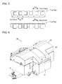
- the carrier tapes T1 and T2 there is an embossed tape T1e (T2e) of which the pitch Pc of the cavities Ct1 (Ct2) are different from each other, or in which the cavities (embossed portions) Cte1 (Cte2) protrude in a thickness direction as illustrated in Fig. 5 .
- the different types of the carrier tapes can also be connected by the splicing apparatus 20.
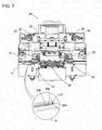
- the two carrier tapes T1 and T2 to be spliced are fed from the right and left in Fig. 7 , and a protection tape 31 (refer to Fig. 8 ) having the splicing tape 30 which connects the two carrier tapes T1 and T2 to each other pasted therein is fed from above, that is, orthogonal to the right and left in Fig. 7 .
- a protection tape 31 (refer to Fig. 8 ) having the splicing tape 30 which connects the two carrier tapes T1 and T2 to each other pasted therein is fed from above, that is, orthogonal to the right and left in Fig. 7 .
- end portions of the two carrier tapes T1 and T2 are connected to each other by the splicing tape 30 at a splicing position LS where the carrier tapes T1 and T2 intersect with the protection tape 31.
- the splicing tape 30 pasted on the protection tape 31 is fed into the splicing position LS causing a glue face between the carrier tapes T1 and T2 to face upward, and the two carrier tapes T1 and T2 are positioned above the splicing tape 30.
- the splicing tape 30 is configured to include one set of splicing tapes 30a and 30b for a front face and a rear face which are glued onto both faces across the two carrier tapes T1 and T2.
- the splicing tape 30 is configured to form one set including the front face splicing tape 30a which is bonded onto the front face sides of the two carrier tapes T1 and T2 and the rear face splicing tape 30b which is bonded onto the rear face sides of the two carrier tapes T1 and T2.
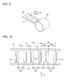
- the one set of the splicing tapes 30 for the front face and the rear face is pasted on the protection tape 31 in the longitudinal direction at regular pitch intervals Pd while maintaining a regular positional relationship with respect to feeding holes 31a which are bored on both the sides of the protection tape 31 at regular pitch intervals.
- metal powder is embedded in the one set of the splicing tapes 30a and 30b so as to be detectable by the below-described metal detection sensors 48 and 49.
- two metal detection sensors 48 and 49 which detect the splicing tapes 30a and 30b are disposed below the protection tape 31 at predetermined intervals. Specifically, when the one set of the splicing tapes for the front face and the rear face (first splicing tapes) 30 are positioned at the splicing position LS, the two metal detection sensors 48 and 49 are disposed at positions where the two metal detection sensors 48 and 49 are turned on by the front face splicing tape 30a of the successive one set of the splicing tapes (second splicing tapes) 30 and the rear face splicing tape 30b of the next successive one set of the splicing tapes (third splicing tapes). In states other than those thereof, the two metal detection sensors 48 and 49 are prevented from being simultaneously turned on (refer to Figs. 13 (B) to 13(E) ).
- the upper faces of the splicing tapes 30a and 30b are formed to be adhesive faces which are glued onto both faces across the two carrier tapes T1 and T2. As illustrated in Fig. 9 , a continuous paper mount 32 is glued onto the glue face thereof. A three-layer structure body including the paper mount 32, the splicing tape 30, and the protection tape 31 is wound around a supply reel 33 in a rolled manner.
- the measurement of the protection tape 31 in the width direction is greater than the measurement of the paper mount 32 in the width direction, and both ends of the protection tape 31 in the width direction protrude further than both ends of the paper mount 32 in the width direction.
- the measurement of the splicing tape 30 in the width direction is equivalent to the measurement of the paper mount 32 in the width direction, and the splicing tape 30 is pasted on the protection tape 31 forming one set with the splicing tapes for the front face and the rear face on the inner side of the feeding hole 31a.
- a plurality of positioning holes 31b are formed in the protection tape 31 along the protection tape 31 in the width direction at the same pitch intervals as those of the sprocket holes Hc1 and Hc2 which are formed in the carrier tapes T1 and T2 at a position near the front face splicing tape 30a.
- a plurality of positioning holes 30b1 are formed so as to penetrate the protection tape 31 in the rear face splicing tape 30b along the protection tape 31 in the width direction at the same pitch intervals as those of the sprocket holes Hc1 and Hc2 which are formed in the carrier tapes T1 and T2.
- the feeding holes 31a and the positioning holes 31b formed in the protection tape 31 are formed through punching-pressing in association with forming of the positioning holes 30b1 performed in the splicing tape 30b after the splicing tapes 30a and 30b are pasted on the protection tape 31 at a predetermined position.
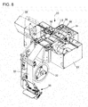
- the rotatable supply reel 33 around which the three-layer structure body including the splicing tape 30 is wound in a rolled manner, a paper mount feeding device 35 which feeds the paper mount 32 caused to peel off from the splicing tape 30, and a protection tape feeding device 36 which feeds the protection tape 31 from which the splicing tape 30 peels off are arranged on a line crossing the splicing position LS where the two carrier tapes T1 and T2 are spliced.
- the glue force with respect to the protection tape 31 is stronger than the other. Therefore, even though the paper mount 32 is caused to peel off from the splicing tape 30, the splicing tape 30 is prevented from peeling off from the protection tape 31.
- the carrier tapes T1 and T2 are glued onto the glue face of the splicing tape 30 from which the paper mount 32 is peeled off, the adhesive force thereof is stronger than the adhesive force with respect to the protection tape 31. Therefore, the protection tape 31 is likely to peel off from the splicing tape 30.
- the three-layer structure body including the paper mount 32, the splicing tape 30, and the protection tape 31 is mounted in the splicing apparatus 20 in a state of being wound around the supply reel 33, and the distal end thereof is drawn out from the supply reel 33. Then, a worker peels off and folds back the paper mount 32 to, and the paper mount 32 is fed by the paper mount feeding device 35 and is discarded into a paper mount accommodation box (not illustrated).
- the protection tape 31 from which the paper mount 32 is peeled off that is, the protection tape 31 in which multiple splicing tapes 30 are pasted with the glue face thereof facing upward passes through the below-described bonding device 58 so as to cross the center of the splicing position LS, and thus, the distal end portion of the protection tape 31 engages with a feeding sprocket 46 (refer to Fig. 12 ) of the protection tape feeding device 36.
- the protection tape 31 which engages with the engagement teeth 46a is fed by a unit quantity by forming a plurality of engagement teeth 46a at equiangular intervals in a circumferential direction at the same pitch as the pitch of the feeding holes 31a bored in the protection tape 31 and driving a stepping motor 47 connected to the feeding sprocket 46 by one pitch.
- the stepping motor 47 returns to the original position as power is supplied, and an engagement teeth 46a of the feeding sprocket 46 is positioned so as to be at the apex at all times.
- the protection tape 31 (the splicing tape 30) is fed by a unit quantity ⁇ Pd as illustrated in Figs. 13 (A) to 13 (F) in accordance with the stepping motor 47 driven by one pitch and the feeding thereof is repeated N times (for example, 5 times), the protection tape 31 is fed by only the pitch Pd of one set of the splicing tapes 30, and thus, one set of the splicing tapes 30 for the front face and the rear face is sequentially conveyed to the splicing position LS.
- the splicing apparatus 20 includes the first and second tape feeding devices 50 and 51, first and second component detection devices 52 and 53, first and second cutting devices 54 and 55, first and second take-in devices 56 and 57, the bonding device 58, and a control device 59 (refer to Fig. 6 ).
- the first and second tape feeding devices 50 and 51, the first and second cutting devices 54 and 55, the first and second take-in devices 56 and 57, the bonding device 58 (excluding a portion thereof), and the control device 59 are accommodated and disposed inside the casing 21 covered with the lid body 22.
- the first and second tape feeding devices 50 and 51 are respectively disposed on both the sides in the casing 21 covered with the lid body 22.
- the first and second cutting devices 54 and 55 are respectively disposed between the first and second tape feeding devices 50 and 51.
- the first and second take-in devices 56 and 57 are respectively disposed between the first and second cutting devices 54 and 55.
- the bonding device 58 is disposed between the first and second take-in devices 56 and 57.
- the first and second component detection devices 52 and 53 are disposed above first and second detection positions Ld1 and Ld2 of first and second conveyance paths 60a and 60b in the first and second tape feeding devices 50 and 51.
- the first and second tape feeding devices 50 and 51 include the first and second conveyance paths 60a and 60b which are provided so as to extend from both the side faces in the casing 21 toward the center in a horizontal direction, the first and second sprockets 61a and 61b which are disposed below the first and second conveyance paths 60a and 60b, first and second stepping motors 62a and 62b which are connected to the first and second sprockets 61a and 61b, first and second sprocket tooth detection devices 63a and 63b which are disposed in the vicinity of the first and second sprockets 61a and 61b, first and second tape detection devices 64a and 64b which are disposed above the first and second conveyance paths 60a and 60b, and the like.
- the first and second tape feeding devices 50 and 51 are configured to convey the first and second carrier tapes T1 and T2 in the first and second conveyance paths 60a and 60b, and to be able to position the first and second cutting places Q1 and Q2 (refer to Fig. 4 ) of the first and second carrier tapes T1 and T2 sequentially at first and second cutting positions Lc1 and Lc2, and the splicing position LS.
- the first and second conveyance paths 60a and 60b have widths slightly greater than the widths of the first and second carrier tapes T1 and T2, and are formed to have groove shapes extending in straight lines from first and second tape entrances 84a and 84b provided on both the side faces in the casing 21 to the first and second cutting positions Lc1 and Lc2 of the first and second carrier tapes T1 and T2 which are cut by first and second cutters 68a and 68b of the first and second cutting devices 54 and 55.
- first and second micro grooves 65a and 65b for allowing the first and second cavities Cte1 and Cte2 of the first and second embossed tapes T1e and T2e having the first and second components e1 and e2 accommodated therein are formed in the first and second conveyance paths 60a and 60b.
- first and second leaf springs 66a and 66b are fixedly disposed on the sides of the first and second cutting positions Lc1 and Lc2 of the first and second micro grooves 65a and 65b.
- the first and second leaf springs 66a and 66b are curved to have a concave shape and are fixedly disposed so as to incline obliquely upward and gradually toward the first and second cutting positions Lc1 and Lc2.
- the first and second leaf springs 66a and 66b are members which operate when the first and second embossed tapes T1e and T2e are cut and conveyed.
- a plurality of the first and second teeth 67a and 67b are formed in the first and second sprockets 61a and 61b in the circumferential direction having the same pitch as the pitch Ph of the first and second sprocket holes Hc1 and Hc2 which are bored in the first and second carrier tapes T1 and T2.
- the first and second sprockets 61a and 61b are disposed below the first and second conveyance paths 60a and 60b so as to be able to mesh with the first and second sprocket holes Hc1 and Hc2 of the first and second conveyance paths 60a and 60b which are inserted along the first and second carrier tapes T1 and T2.
- the first and second sprocket tooth detection devices 63a and 63b detect that the first and second sprockets 61a and 61b are at the original positions by reading first and second marks M1 and M2 applied on the side faces of the first and second sprockets 61a and 61b.
- the first and second tape detection devices 64a and 64b detect that the first and second carrier tapes T1 and T2 are inserted from the first and second tape entrances 84a and 84b provided on both the side faces in the casing 21.
- the first and second component detection devices 52 and 53 detect the first and second cavities Ct1 and Ct2 of the first and second carrier tapes T1 and T2 which are conveyed through the first and second conveyance paths 60a and 60b, a tape portion between the first and second cavities Ct1 and Ct2, and first and second components e1 and e2 inside the first and second cavities Ct1 and Ct2.
- the first and second cutting devices 54 and 55 include the first and second cutters 68a and 68b which are provided in the first and second cutting positions Lc1 and Lc2, first and second cams 69a and 69b which can come into sliding contact with the first and second cutters 68a and 68b, first and second gear motors 70a and 70b which are connectively in contact with the first and second cams 69a and 69b, first and second cutter springs 71a and 71b in which one end of each is attached to each of the first and second cutters 68a and 68b and the other end of each is attached to the inner side of the lid body 22, first and second pressing members 72a and 72b which are provided adjacent to the first and second cutters 68a and 68b, first and second pressing springs 73a and 73b in which one end of each is attached to each of the first and second cutters 68a and 68b and the other end of each is attached to each of the first and second pressing members 72
- the first and second cutting devices 54 and 55 are configured to be able to cut the first and second unnecessary portions Tf1 and Tf2 (refer to Fig. 17 ) in the first and second cutting places Q1 and Q2 of the first and second carrier tapes T1 and T2.
- the first and second cutters 68a and 68b are installed so as to be movable in a vertical direction, thereby moving in accordance with rotations of the first and second cams 69a and 69b.
- the first and second pressing members 72a and 72b are provided so as to be movable in the vertical direction and are biased downward by the first and second pressing springs 73a and 73b.
- the first and second take-in devices 56 and 57 are configured to include first and second take-in members 75a and 75b which are provided between the first and second cutting positions Lc1 and Lc2 and the splicing position LS and are turnably supported by first and second fixing members 78a and 78b, first and second take-in member turning devices 76a and 76b which turn the first and second take-in members 75a and 75b, and the like.
- the first and second take-in devices 56 and 57 are configured to be able to respectively take the cut first and second unnecessary portions Tf1 and Tf2 of the first and second carrier tapes T1 and T2.
- First and second openings 80a and 80b for taking the first and second unnecessary portions Tf1 and Tf2 of the first and second carrier tapes T1 and T2 which are conveyed through the first and second conveyance paths 60a and 60b, and first and second ducts 82a and 82b for guiding the first and second unnecessary portions Tf1 and Tf2 to a dumping place (not illustrated) are formed in the first and second take-in members 75a and 75b.
- first and second take-in members 75a and 75b are retained at the original positions indicated by the dot-and-dash line in Fig. 15 .
- the first and second take-in member turning devices 76a and 76b turn the first and second take-in members 75a and 75b by a predetermined angle so as to cause first and second movable conveyance paths 79a and 79b formed in the first and second take-in members 75a and 75b to be aligned with the first and second conveyance paths 60a and 60b.
- the bonding device 58 is provided between the first cutting device 54 and the second cutting device 55.
- the bonding device 58 is configured to be able to connect the first and second carrier tapes T1 and T2 to each other at the splicing position LS in the middle of the first and second conveyance paths 60a and 60b where the first and second cutting places Q1 and Q2 are caused to abut each other, by using the splicing tape 30.
- the bonding device 58 includes a first lifting and lowering table 91, a pressing plate 97, a second lifting and lowering table 101, a swivel table 103, and the like. Leg portions 92 of the first lifting and lowering table 91 are guided and supported by the casing 21 so as to be able to be lifted and lowered.
- each of first positioning pins 93 and 94 which can engage with the positioning holes 30b1 formed in the splicing tape 30b, and each of the sprocket holes Hc of the two carrier tapes T1 and T2 are provided protruding along the carrier tapes T1 and T2 in a feeding direction on both the sides having a bonding position (an abutting position) of the two carrier tapes T1 and T2 as the center.
- Each pitch of the two sets of the first positioning pins 93 and 94 is set to be twice the pitch P of the sprocket holes Hc in the carrier tapes T1 and T2.
- a pin hole 95 is formed between each set of the first positioning pins 93 and 94, and second positioning pins 105 on the below-described swivel table 103 side can be inserted into the pin holes 95.
- a movable table 96 is movably guided and supported by the casing 21 in the horizontal direction orthogonal to the longitudinal direction of the carrier tapes T1 and T2.
- the pressing plate 97 is attached to the movable table 96 at a position above the first positioning pins 93 and 94.
- U-shaped grooves 98 which can accommodate the first positioning pins 93 and 94 are formed at the distal end of the pressing plate 97.
- the pressing plate 97 can move forward and rearward between positions of a rearward movement end at which the grooves 98 escape from the first positioning pins 93 and 94 and a forward movement end at which the grooves 98 accommodate the first positioning pins 93 and 94.
- leg portions 102 of the second lifting and lowering table 101 are guided and supported by the casing 21 so as to be able to be lifted and lowered.
- both ends of the swivel table 103 are supported having a pivot shaft 104 which is parallel to the longitudinal direction of the carrier tapes T1 and T2 as the swivel center, so as to be swivelable 180 degrees.
- a pressing plate 103a is provided in the swivel table 103 at a position offset from the swivel center.
- a plurality of the second positioning pins 105 and pin holes 106 are provided in the pressing plate 103a.
- Each of the second positioning pins 105 is arranged at a position corresponding to the middle of the first positioning pins 93 and 94 which are provided on the first lifting and lowering table 91, and is able to be inserted into the pin hole 95 which is provided in the first lifting and lowering table 91.
- each of the pin holes 106 is arranged at a position corresponding to the middle of the second positioning pins 105, and the first positioning pins 93 and 94 which are provided on the first lifting and lowering table 91 can be inserted therein.
- the second positioning pins 105 engage with the sprocket holes Hc of the two carrier tapes T1 and T2 which are positioned at the splicing position LS and the positioning holes 30b1 of the splicing tape 30b so that positional relationships are regularly maintained among the three, that is, the two carrier tapes T1 and T2 and the splicing tape 30 which connects the two carrier tapes T1 and T2 to each other.
- Pinions 107 are attached to the pivot shaft 104 of the swivel table 103, and racks 108 which mesh with the pinions 107 are attached to a movable table 109 which is movable in the horizontal direction orthogonal to a conveyance direction of the carrier tapes T1 and T2. Accordingly, as the movable table 109 moves, the swivel table 103 is caused to swivel by rack and pinion mechanisms each of which includes the pinion 107 and the rack 108.
- the three of the two carrier tapes T1 and T2 and the splicing tape 30 are pinched between the pressing plate 103a and the first lifting and lowering table 91, thereby being connected to one another.
- sufficiently elastic rubber sheets 121 and 122 are respectively attached to the first lifting and lowering table 91 and the pressing plate 103a.
- the rubber sheets 121 and 122 are provided in order to precisely splice the carrier tape by using the splicing tape 30, regardless of whether the type of the carrier tape to be spliced is the paper tape or the embossed tape.
- the rubber sheet 121 attached to the first lifting and lowering table 91 includes a step difference 121a which is formed by lowering a side provided with the cavities Ct1 and Ct2 with respect to a side provided with the sprocket holes Hc1 and Hc2 of the carrier tapes T1 and T2.
- the rubber sheet 122 attached to the pressing plate 103a includes a step difference 122a which is formed by raising a side provided with the cavities Ct1 and Ct2 with respect to a side provided with the sprocket holes Hc1 and Hc2. Then, as illustrated in Fig. 26(A) , in step difference amounts d1 and d2 of both the rubber sheets 121 and 122, the rubber sheet 122 attached to the pressing plate 103a is caused to be greater than the other (d1 ⁇ d2).
- the aforementioned configuration is made in order to reliably glue the splicing tape 30 onto the irregular face as well, since the embossed tape has the flat front face and the rear face which includes the irregularly protruding cavities Ct1 and Ct2, compared to the paper tape in which both the front face and the rear face are flat faces.
- the carrier tapes T1 and T2 (the paper tapes) are pinched by the first lifting and lowering table 91 and each of the rubber sheets 121 and 122 of the pressing plate 103a, the higher step difference portion of the rubber tape is deformed and the splicing tape 30 is bonded onto the carrier tapes T1 and T2.
- the carrier tapes T1 and T2 (the embossed tapes) are pinched by the first lifting and lowering table 91 and each of the rubber sheets of the pressing plate 103a, since the cavities Ct1 and Ct2 can be accommodated in the lower step difference portion of the rubber sheet 121 on the first lifting and lowering table 91, the splicing tape 30 can be bonded without adding excessive pressure to the cavities Ct1 and Ct2.
- the rubber sheet 122 attached to the pressing plate 103a is caused to be greater than the other regarding step difference between both the rubber sheets 121 and 122, when splicing the embossed tape, the rear face splicing tape can be reliably bonded onto the cavities Ct1 and Ct2 by pinching the cavities Ct1 and Ct2 with a greater elastic force (compression allowance).
- a cam drum 110 is rotatably supported in the casing 21 around the axial line which is parallel to the swivel center of the swivel table 103, thereby rotating slowly in a regular direction by a drive motor (not illustrated).
- a drive motor not illustrated
- two sets of inner and outer cam grooves 110a and 110b, and 110c and 110d are respectively and endlessly formed in the circumferential direction.
- a first follower roller which is pivotally supported by the leg portions 92 of the first lifting and lowering table 91 engages with the first cam groove 110a.
- a second follower roller which is pivotally supported by the movable table 96 connected to the pressing plate 97 engages with the second cam groove 110b.
- a third follower roller which is pivotally supported by the leg portions 102 of the second lifting and lowering table 101 engages with the third cam groove 110c.
- a fourth follower roller (not illustrated) which is pivotally supported by a connection member 112 connected to the movable table 109 engages with the fourth cam groove 110d.
- the splicing apparatus 20 is provided with a locking device 24 which locks the lid body 22 in a closed state during a splicing operation.
- the locking device 24 is mainly configured to include a solenoid 25 which is installed in the casing 21 and is able to actuate an actuation rod 25a in the vertical direction, a hook 27 which is turnably supported by the casing 21 centering around a pivot 26 and is caused to turn by the solenoid 25, and an engagement pin 28 which is provided in the lid body 22 so as to protrude downward and disengageably engages with the hook 27.
- An opening spring 29 which biases the lid body 22 in an opening direction is provided between the casing 21 and the lid body 22.
- the lid body 22 is automatically moved by the opening spring 29 so as to uncover the inside.
- a dog (not illustrated) is provided in the lid body 22, and the casing 21 is provided with a closed-state confirmation sensor which is operated by the dog.
- the closed-state confirmation sensor is operated by the dog when covering the inside with the lid body 22, and a closed state of the lid body 22 is confirmed based on an ON signal of the closed-state confirmation sensor.
- the actuation rod 25a of the solenoid 25 is actuated in the upward direction of Fig. 23 and the hook 27 is caused to turn so as to engage with the engagement pin 28, based on the ON signal. Accordingly, the lid body 22 is locked in a closed state by the locking device 24.
- the splicing apparatus 20 When the remaining quantity of the components e retained in the first carrier tape T1 which is attached to the tape feeder 10 wound around the reel 12 decreases, splicing processing for causing the leading end portion of the second carrier tape T2 which is wound around another reel accommodating the same types of the components e to be connected to the trailing end portion of the first carrier tape T1 is executed by the splicing tape 30.
- the components can be reloaded through such splicing processing, and thus, the tape feeder 10 can continue to supply the components.
- verifying of splicing processing is generally executed in order to check whether or not the carrier tape accommodating the right components is connected thereto.
- verifying of splicing processing a barcode labelled on an old reel is read by a barcode reader, and the serial ID of the components accommodated in the old reel is transmitted to a management computer.
- a barcode labelled on a new reel is read by the barcode reader, and the serial ID of the components accommodated in the new reel is transmitted to the management computer.
- each end portion of the two carrier tapes T1 and T2 is cut with scissors.
- a vacant cavity portion having no component accommodated therein is provided at the end portion of each of the carrier tapes T1 and T2 to the extent of several tens of millimeters, the portion is cut by a worker.
- the cut faces are not the abutting faces of the two carrier tapes T1 and T2, accuracy is not particularly required.
- the lid body 22 is placed to cover the inside thereof.
- the control device 59 causes the stepping motors 62a and 62b to return to the original positions, based on detection signals from the first and second sprocket tooth detection devices 63a and 63b.
- the control device 59 detects whether or not the distal end portions of the first and second tapes T2 are inserted from the first and second tape entrances 84a and 84b, based on detection signals from the first and second tape detection devices 64a and 64b.
- the stepping motors 62a and 62b start so as to rotate the first and second sprockets 61a and 61b, and cause movable members 77a and 77b of the first and second take-in members 75a and 75b to move upward.
- control device 59 sequentially detects the first vacant cavities Ct1 and Ct2, and the second vacant cavities Ct1 and Ct2 which do not include the components e1 and e2 in the first and second tapes T1 and T2, based on detection signals from the first and second tape detection devices 64a and 64b, thereby calculating the pitch Pc between the cavities Ct1 and Ct2 based on the detection of the first and second cavities Ct1 and Ct2.
- the control device 59 calculates the cutting places Q1 and Q2 (refer to Fig. 4 ) of the first and second tapes T1 and T2 based on the pitch Pc between the cavities Ct1 and Ct2, and distances D1 and D2 between the known detection positions L d1 and L d2 and the known cutting positions Lc1 and Lc2. Then, as illustrated in Fig. 16 , the first and second tapes T1 and T2 are moved by the distances D1 and D2, and the unnecessary portions Tf1 and Tf2 are taken in the first and second take-in members 75a and 75b, thereby conveying and positioning the cutting places Q1 and Q2 to the cutting positions Lc1 and Lc2.
- the control device 59 causes each of the cutters 68a and 68b to be lowered together with the pressing members 72a and 72b so as to press and fix the vicinity of the cutting places Q1 and Q2 of the first and second carrier tapes T1 and T2 which are positioned at the cutting positions Lc1 and Lc2, by using the pressing members 72a and 72b.
- each of the cutters 68a and 68b is lowered so as to cut each of the cutting places Q1 and Q2 of the first and second carrier tapes T1 and T2.
- the unnecessary portions Tf1 and Tf2 cut off from the first and second carrier tapes T1 and T2 are guided into the ducts 82a and 82b of the take-in members 75a and 75b, thereby being discarded.
- the control device 59 causes the take-in members 75a and 75b to move downward. Thereafter, each of the sprockets 61a and 61b is caused to rotate by the stepping motors 62a and 62b, and the first and second carrier tapes T1 and T2 are moved respectively by the known distances D3 and D4 from the cutting positions Lc1 and Lc2 to the splicing position LS, thereby conveying and positioning the cutting places Q1 and Q2 of the first and second carrier tapes T1 and T2 at the splicing position LS.
- the sprocket holes Hc1 and Hc2 of the first and second carrier tapes T1 and T2 are positioned at positions so as to be able to engage with the first positioning pins 93 and 94 of the bonding device 58 provided at the splicing position LS.
- the above-described first and second tape feeding devices 50 and 51 and the like configure a positioning device for positioning the first and second carrier tapes T1 and T2 at the splicing position LS where the positioning pins 93 and 94 respectively engage with the sprocket holes Hc1 and Hc2 of the first and second carrier tapes T1 and T2.
- the distal ends of the first and second carrier tapes T1 and T2 inserted from the first and second tape entrances 84a and 84b are positioned at the splicing position LS without causing a misaligned pitch.
- the three-layer structure body including the paper mount 32, the splicing tape 30, and the protection tape 31 wound around the supply reel 33 is drawn out from the supply reel 33, and the paper mount 32 is peeled off, thereby being fed by the paper mount feeding device 35.
- the protection tape 31 having the splicing tape 30 pasted thereto is fed by the protection tape feeding device 36, and thus, one set of the splicing tapes 30 for the front face and the rear face is conveyed to the splicing position LS.
- the stepping motor 47 of the protection tape feeding device 36 feeds the splicing tape 30 by the unit quantity ⁇ Pd as illustrated in Fig. 13 and the feeding thereof is repeated N times (5 times in the embodiment), one set of the splicing tapes 30 for the front face and the rear face is fed by only the pitch Pd, thereby being conveyed to the splicing position LS, as illustrated in Fig. 13(F) .
- one set of the splicing tapes 30 for the front face and the rear face is conveyed to the splicing position LS, one side of the successive one set of the splicing tapes 30, that is, the front face splicing tape 30a is detected by the first metal detection sensor 48, and at the same time, the rear face splicing tape 30b of the next successive one set of the splicing tapes 30 is detected by the second metal detection sensor 49.
- the positioning is performed at a position where the positioning holes 30b1 formed in the rear face splicing tape 30b can engage with the first positioning pins 93 and 94 of the bonding device 58 provided at the splicing position LS (refer to Fig. 25 ).
- the splicing tape 30 is positioned at the splicing position LS, if the first and second carrier tapes T1 and T2 are not positioned at the splicing position LS, the splicing tape 30 is on standby until the first and second carrier tapes T1 and T2 are positioned at the splicing position LS.
- the drive motor rotates the cam drum 110.
- the first lifting and lowering table 91 rises through the first follower roller (not illustrated) which engages with the first cam groove 110a.
- the first positioning pins 93 and 94 respectively engage with the positioning holes 30b1 in the rear face splicing tape 30b and each of the sprocket holes Hc in the two carrier tapes T1 and T2.
- the carrier tapes T1 and T2 are not glued onto the rear face splicing tape 30b. Accordingly, the positional relationships among the three, that is, the two carrier tapes T1 and T2 and the rear face splicing tape 30b which is glued onto the rear face sides of the two carrier tapes T1 and T2 can be regularly maintained.
- the movable table 96 moves in the horizontal direction through the second follower roller (not illustrated) which engages with the second cam groove 110b.
- the pressing plate 97 which is interposed between the rear face splicing tape 30b and the carrier tapes T1 and T2 moves rearward with respect to the first lifting and lowering table 91.
- the rear face splicing tape 30b can be glued onto the carrier tapes T1 and T2.
- the movable table 109 moves horizontally through the third follower roller (not illustrated) which engages with the third cam groove 110c.
- the swivel table 103 swivels in the clockwise direction of Fig. 22 by the rack and pinion mechanism (107 and 108).
- the protection tape 31 engaging with the second positioning pins 105 is bent, and the front face splicing tape 30a is turned over with the glue face facing downward at a position above the carrier tapes T1 and T2.
- the protection tape 31 is bent so as to clamp the carrier tapes T1 and T2 therebetween.
- the rear face splicing tape 30b is positioned on the rear face sides of the carrier tapes T1 and T2
- the front face splicing tape 30a is positioned on the front face sides of the carrier tapes T1 and T2.
- the motor of the protection tape feeding device 36 rotates reversely so as to impart slackness to the protection tape 31, thereby allowing the protection tape 31 to be bent.
- the second lifting and lowering table 101 is lowered through the fourth follower roller (not illustrated) which engages with the fourth cam groove 110d.
- the second positioning pins 105 engage with the positioning holes 31b of the protection tape 31, the sprocket holes Hc of the carrier tapes T1 and T2, and the positioning holes 30b1 of the rear face splicing tape 30b from the rear side of the protection tape 31.
- the bent protection tape 31 is pressed between the pressing plate 103a of the swivel table 103 and the first lifting and lowering table 91. Due to the pressing, the rear face splicing tape 30b pasted on the protection tape 31 is glued across the rear faces of the carrier tapes T1 and T2, and the front face splicing tape 30a is glued across each of the top tapes Tt which are pasted on the front faces of the carrier tapes T1 and T2.
- the pressed state lasts for a certain time (for several seconds).
- the pressing plate 103a and the first lifting and lowering table 91 are provided with the rubber sheets 121 and 122 which respectively include the step differences 121a and 122a.
- the rubber sheets 121 and 122 are elastically deformed so as to be flat following after the front face and the rear face of the carrier tapes T1 and T2.
- the two carrier tapes T1 and T2 are connected by the splicing tape 30 in a state where the carrier tapes T1 and T2 and the splicing tapes 30a and 30b are restricted in relative misalignment by the first and second positioning pins 93, 94, and 105, the two carrier tapes T1 and T2 can be accurately bonded without causing misalignment of the pitch.
- Bonding of the two carrier tapes T1 and T2 performed by the splicing tape 30 is achieved in accordance with the 180-degree rotation of the cam drum 110, and each of the constituting members return to the original position in accordance with the remaining 180-degree rotation due to an operation opposite to that described above.
- the second lifting and lowering table 101 rises first, and the swivel table 103 rises with respect to the first lifting and lowering table 91. Then, the pressed state of the bent protection tape 31 is released, and the second positioning pins 105 escape from the positioning holes 30b1 of the rear face splicing tape 30b and each of the sprocket holes Hc of the two carrier tapes T1 and T2.
- the protection tape 31 since the splicing tape 30 has high adhesiveness with respect to the carrier tapes T1 and T2, the protection tape 31 easily peels off from the splicing tape 30 due to a returning force of the spring of the protection tape 31 generated by releasing the pressed state of the protection tape 31, and thus, the splicing tape 30 is not peeled off from the carrier tapes T1 and T2.
- the swivel table 103 swivels in the counterclockwise direction of Fig. 21 through the rack and pinion mechanism (108 and 107), and the motor of the protection tape feeding device 36 rotates forward, thereby eliminating the slackness of the protection tape 31.
- the pressing plate 97 moves forward, and the first lifting and lowering table 91 is lowered. Then, the first positioning pins 93 and 94 escape from the positioning holes 30b1 of the rear face splicing tape 30b and each of the sprocket holes Hc of the two carrier tapes T1 and T2. Meanwhile, the motor is driven in the paper mount feeding device 35 so as to apply tension to the paper mount 32, and thus, the paper mount 32 is peeled off as much as necessary. In this manner, bonding between the trailing end portion of the first carrier tape T1 and the leading end portion of the second carrier tape T2 is completed.
- connection completion signal is issued by the control device 59.
- the solenoid 25 of the splicing apparatus 20 is actuated, the actuation rod 25a moves downward, and the hook 27 turns in the clockwise direction of Fig. 24 centering around the pivot 26.
- the hook 27 and the engagement pin 28 are disengaged from each other, and the lid body 22 turns centering around the pivot 23 by the biasing force of the spring 29, thereby automatically uncovering the inside thereof.
- the first and second spliced carrier tapes T1 and T2 are taken out from the splicing apparatus 20 by a worker.
- the reel 12 having the second carrier tape T2 wound therearound is set to the tape feeder 10, thereby completing splicing processing.
- the tape feeder 10 is reloaded with the components, and thus, mounting of the components can be continuously carried out in the component mounting machine without stopping the machine.
- the closed-state confirmation sensor (not illustrated) is turned on by the dog which is fixed onto the lid body 22.
- the solenoid 25 is actuated, and the actuation rod 25a moves upward.
- the hook 27 turns in the counterclockwise direction of Fig. 24 centering around the pivot 26, thereby engaging with the engagement pin 28 fixed onto the lid body 22.
- an actuation confirmation sensor (not illustrated) is turned on by the dog (not illustrated) attached to the hook 27.
- the lid body 22 when the lid body 22 is placed to cover the inside, the lid body 22 cannot be in an open state by an external force. Thus, it is possible to prevent the operation section inside the splicing apparatus 20 from being in contact with a worker during an automatic operation, and to ensure safety. In addition, when splicing is completed, the lid body 22 is automatically moved so as to uncover the inside. Thus, it is possible to enhance workability.
- the splicing apparatus 20 is provided with an operation button (not illustrated) which unlocks the locked state in case of an emergency stop.
- An automatic operation is stopped by operating the operation button during the automatic operation of the splicing apparatus 20 so that the lid body 22 can be manually moved to uncover the inside. In this case, the automatic operation cannot be performed unless the lid body 22 is placed to cover the inside and locked again.
- the stepping motor 47 feeds the splicing tape 30 N times by the unit quantity ⁇ Pd as illustrated in Fig. 13 , and the splicing tape 30 is positioned at the splicing position LS where the first and second metal detection sensors 48 and 49 are simultaneously turned on.
- the first and second carrier tapes T1 and T2 are automatically bonded to each other by the bonding device 58.
- the stepping motor 47 When the lid body 22 of the splicing apparatus 20 is placed to cover the inside and power is supplied, the stepping motor 47 returns to the original position (the engagement tooth 46a of the feeding sprocket 46 is positioned at the apex), and in such a state, the stepping motor 47 intermittently feeds the splicing tape 30 by the unit quantity ⁇ Pd. Accordingly, even though the position of the stepping motor 47 is misaligned while the splicing apparatus 20 is halted, the first splicing tape 30 which is pasted on the forefront of the protection tape 31 can be accurately positioned at the splicing position where the first and second metal detection sensors 48 and 49 are simultaneously turned on.
- the first and second metal detection sensors 48 and 49 are simultaneously turned on. Subsequently, based on the first and second metal detection sensors 48 and 49 which are simultaneously turned on, it is possible to detect that the first splicing tape 30 which is pasted on the forefront of the protection tape 31 is positioned at the splicing position LS.
- first and second carrier tapes T1 and T2 are the embossed tapes T1e and T2e as illustrated in Fig. 5
- first and second cavities Cte1 and Cte2 are conveyed along the inside of the first and second micro grooves 65a and 65b.
- first and second embossed tapes T1e and T2e approach the first and second cutting positions Lc1 and Lc2
- the first and second cavities Cte1 and Cte2 get on the first and second leaf springs 66a and 66b crossing over the first and second cutting positions Lc1 and Lc2
- the first and second cutting places Q1 and Q2 are positioned at the first and second cutting positions Lc1 and Lc2 (refer to Fig. 27(B) ).
- the first and second pressing members 72a and 72b press and fix the first and second cutting places Q1 and Q2 of the first and second embossed tapes T1e and T2e which are positioned at the first and second cutting positions Lc1 and Lc2.
- the first and second cavities Cte1 and Cte2 cause the first and second leaf springs 66a and 66b to be elastically deformed downward so as to be accommodated inside the first and second micro grooves 65a and 65b (refer to Fig. 27(C) ).
- the first and second cutting places Q1 and Q2 of the first and second embossed tapes T1e and T2e are positioned at the first and second cutting positions Lc1 and Lc2 with high accuracy, and thus, it is possible to enhance cutting accuracy of the first and second embossed tapes T1e and T2e.
- the first and second leaf springs 66a and 66b are restored and raise the first and second cavities Cte1 and Cte2 in the vicinity of the first and second cutting positions Lc1 and Lc2 upward from the first and second micro grooves 65a and 65b (refer to Fig. 27(D) ). Accordingly, the first and second cavities Cte1 and Cte2 can get on the first and second leaf springs 66a and 66b crossing over the first and second cutting positions Lc1 and Lc2, and thus, the first and second embossed tapes T1e and T2e can be smoothly conveyed.
- the cavities Cte1 and Cte2 of the embossed tapes T1e and T2e are accommodated at the lower step difference portion of the rubber sheet 121 which is attached to the first lifting and lowering table 91. Therefore, the splicing tapes 30a and 30b can be bonded onto the front face and the rear face of the embossed tapes T1e and T2e due to elastic forces of the rubber sheets 121 and 122 without adding an excessive force to the cavities Cte1 and Cte2.
- the splicing tape 30 can be reliably bonded onto such embossed tapes T1e and T2e having irregularities.
- the embodiment includes the first and second tape feeding devices (the positioning devices) 50 and 51 that feed the first and second carrier tapes T1 and T2 in a direction approaching each other and cause the positioning pins 93 and 94 to be positioned at the splicing position LS so as to be able to engage with the sprocket holes Hc1 and Hc2 of the first and second carrier tapes T1 and T2, the plurality of a set of the splicing tapes 30 (30a and 30b) for the front face and the rear face that is pasted at the splicing position LS on the continuous protection tape 31 fed in a direction orthogonal to the feeding direction of the first and second carrier tapes T1 and T2 and has metal embedded therein, a pair of the metal detection sensors 48 and 49 that is disposed at an interval in the feeding direction of the protection tape 31 and detects the splicing tape 30, and the bonding device 58 that bonds the splicing tapes 30a and 30b fed to the splicing position
- the splicing tapes 30a and 30b are regularly arranged at intervals in the longitudinal direction of the protection tape 31, and the pair of the metal detection sensors 48 and 49 is configured to be simultaneously turned on only when one set of the splicing tapes 30a and 30b is positioned at the splicing position LS.
- the splicing tapes 30a and 30b can be accurately positioned at the splicing position LS so as not to cause the front face splicing tape 30a and the rear face splicing tape 30b to be reversely disposed, and thus, it is possible to acquire the splicing apparatus 20 which can perform highly accurate splicing.
- the protection tape 31 is fed N times by the unit quantity in accordance with rotations of the sprocket 46 which engages with the feeding holes 31a formed at both ends of the protection tape 31 in the width direction
- the splicing tapes 30a and 30b for the front face and the rear face are positioned at positions where the metal detection sensors 48 and 49 are simultaneously turned on. Therefore, feeding accuracy of the protection tape 31 can be enhanced based on a rotation amount of the sprocket 46, and the splicing tapes 30a and 30b can be accurately positioned at the splicing position LS regardless of slackness and the like of the protection tape 31.
- the rubber sheets 121 and 122 having a step difference are respectively provided in the lifting and lowering table 91 and the pressing plate 103a in which the first and second carrier tapes T1 and T2 and the splicing tapes 30a and 30b are pinched and the splicing tapes 30a and 30b are bonded onto the front face and the rear face of the first and second carrier tapes T1 and T2, even though the first and second carrier tapes T1 and T2 have irregularity similar to the embossed tapes T1e and T2e, the splicing tapes 30a and 30b can be reliably bonded onto the front face and the rear face of the embossed tapes T1e and T2e due to an elastic force of the rubber sheet 121 without adding an excessive force to the cavities Cte1 and Cte2 of the embossed tapes T1e and T2e.
- the lid body 22 is locked by the locking device 24 so that the lid body 22 cannot be in an open state by an external force. Therefore, it is possible to prevent the operation section inside the splicing apparatus 20 from being in contact with a worker during an automatic operation, and to ensure safety. In addition, when splicing is completed, the lid body 22 can be automatically moved so as to uncover the inside. Thus, it is possible to enhance workability.
- the splicing tapes 30a and 30b are detected by the metal detection sensors 48 and 49.
- the splicing tape can be detected by a method other than the method of detecting metal.
- the positioning devices (the first and second tape feeding devices) 50 and 51 for positioning the first and second carrier tapes T1 and T2 at the splicing position LS, the protection tape feeding device 36 for feeding the protection tape 31 in which the splicing tapes 30a and 30b are pasted, the bonding device 58 for bonding the splicing tapes 30a and 30b onto the first and second carrier tapes T1 and T2 at the splicing position LS, and the like are only exemplified configurations which are suitable for executing the present invention.
- the present invention is not limited to the configuration described in the embodiment.
- 20 ... splicing apparatus; 21 ... casing; 22 ... lid body; 24 ... locking device; 30 (30a, 30b) ... splicing tape; 31 ... protection tape; 31a ... feeding hole; 36 ... protection tape feeding device; 46 ... sprocket; 47 ... stepping motor; 48, 49 ... sensor (metal detection sensor) ; 50, 51 ... positioning device (tape feeding device); 58 ... bonding device; 93, 94, 105 ... positioning pin; T1, T2 ... carrier tape; Hc1, Hc2 ... sprocket hole; Ct1, Ct2 ... cavity; LS ... splicing position.
Abstract
Description
- The present invention relates to a splicing apparatus which connects two carrier tapes to each other, and a method of detecting a splicing tape that is used in the splicing apparatus.
- Generally, in a component mounting machine, a carrier tape which retains a plurality of electronic components at regular intervals is wound around a reel and a sprocket which engages with sprocket holes bored in the carrier tape is driven so as to feed the carrier tape by a regular quantity and to sequentially supply the electronic components to a component supply position, thereby adsorbing the electronic components by a suction nozzle and mounting the electronic components in a circuit board.
- In such a type of the component mounting machine, when the remaining quantity of the electronic components retained in one reel decreases, so-called splicing processing for causing a leading end portion of the carrier tape which is wound around another reel retaining the same types of the electronic components to be connected to a trailing end portion of the carrier tape of which the remaining quantity decreases is executed, by the splicing tape. PTL 1 discloses a device which includes such a splicing function.
- PTL 1:
JP-A-2007-335595 - Incidentally, in recent years, attempts have been made to perform splicing automatically. However, in order to perform splicing automatically, a splicing tape needs to be automatically conveyed to a splicing position. Generally, the splicing tape is configured to form one set of the splicing tapes including a front face splicing tape for connecting a front face side of a carrier tape and a rear face splicing tape for connecting a rear face side of the carrier tape, and it is important that the front face splicing tape and the rear face splicing tape are accurately positioned at the splicing position so as not to be reversely disposed, when being automated.
- An object of the present invention is to provide a splicing apparatus in which the one set of the splicing tapes for a front face and a rear face connecting the two carrier tapes to each other can be accurately positioned at the splicing position, and a method of detecting a splicing tape that is used in the splicing apparatus.
- In order to achieve the object described above, according to the invention of Claim 1, there is provided a splicing apparatus in which a first carrier tape and a second carrier tape provided with sprocket holes and component accommodation cavities at regular intervals are connected to each other by a splicing tape. The splicing apparatus includes a positioning device that feeds the first and second carrier tapes in a direction approaching each other and causes positioning pins to be positioned at a splicing position so as to be able to engage with the sprocket holes of the first and second carrier tapes, a plurality of the splicing tapes that are pasted at the splicing position on a continuous protection tape fed in a direction orthogonal to a feeding direction of the first and second carrier tapes and form one set with a front face splicing tape for connecting a front face side of the carrier tape and a rear face splicing tape for connecting a rear face side of the carrier tape, a pair of sensors that is disposed at an interval in the feeding direction of the protection tape and detects the splicing tapes, and a bonding device that bonds the splicing tapes fed to the splicing position onto both faces across the first and second carrier tapes. The splicing tapes are regularly arranged at intervals in a longitudinal direction of the protection tape, and the pair of sensors is configured to be simultaneously turned on only when the one set of the splicing tapes is positioned at the splicing position.
- According to the invention of Claim 1, since it is possible to detect that the one set of the splicing tapes for the front face and the rear face is positioned at the splicing position as the pair of sensors is simultaneously turned on, the front face splicing tape and the rear face splicing tape can be accurately positioned at the splicing position so as not to be reversely disposed, and thus, it is possible to acquire the splicing apparatus which can perform highly accurate splicing.
- Accordingly, when the protection tape having the splicing tape pasted thereon is set to the splicing apparatus, it is possible to detect that a first splicing tape is accurately positioned at the splicing position, by using the pair of sensors, and it is possible to detect disconnection of the splicing tape based on a state in which the pair of sensors is not simultaneously turned on even though a predetermined quantity of the splicing tapes is fed.
- According to the invention of Claim 2, in the splicing apparatus according to Claim 1, metal is embedded in the splicing tape and the sensor is formed to be a metal detection sensor which detects metal.
- According to the invention of Claim 2, it is possible to simply and reliably detect the splicing tape by using the metal detection sensor by only embedding metal in the splicing tape.
- According to the invention of
Claim 3, in the splicing apparatus according to Claim 1 or 2, the one set of the splicing tapes is positioned at positions where the pair of sensors is simultaneously turned on by forming feeding holes at both ends of the protection tape in a width direction and rotating a sprocket which engages with the holes so as to feed the protection tape N times by a unit quantity. - According to the invention of
Claim 3, since feeding accuracy of the protection tape can be enhanced based on a rotation amount of the sprocket, it is possible to accurately position the splicing tape at the splicing position regardless of slackness and the like of the protection tape. - According to the invention of Claim 4, there is provided a method of detecting a splicing tape that is used in a splicing apparatus in which a first carrier tape and a second carrier tape provided with sprocket holes and component accommodation cavities at regular intervals are connected to each other by the splicing tape. One set of the splicing tapes for the front face and the rear face which is glued onto both faces across the first and second carrier tapes positioned at a splicing position are pasted on a protection tape, and a pair of sensors which is disposed at intervals in a feeding direction of the protection tape is simultaneously turned on only when the one set of the splicing tapes is positioned at the splicing position.
- According to the invention of Claim 4, since it is possible to detect that the one set of the splicing tapes for the front face and the rear face is positioned at the splicing position as the pair of sensors is simultaneously turned on, it is possible to acquire a splicing detection method in which the front face splicing tape and the rear face splicing tape can be accurately positioned at the splicing position so as not to be reversely disposed.
- Accordingly, similarly to the invention of Claim 1, when the protection tape having the splicing tape pasted thereon is set to the splicing apparatus, it is possible to detect that the first splicing tape is accurately positioned at the splicing position, by using the pair of sensors, and it is possible to detect disconnection of the splicing tape based on a state in which the pair of sensors is not simultaneously turned on even though a predetermined quantity of the splicing tapes is fed.
-
- [
Fig. 1] Fig. 1 is a diagram illustrating a tape feeder which is suitable for executing the present invention. - [
Fig. 2] Fig. 2 is a diagram illustrating a carrier tape which is retained in the tape feeder. - [
Fig. 3] Fig. 3 is a cross-sectional view taken along line 3-3 inFig. 2 . - [
Fig. 4] Fig. 4(A) is a plan view of the carrier tape which is connected by a splicing apparatus, andFig. 4(B) is a diagram of the carrier tape which is seen from the side. - [
Fig. 5] Fig. 5 is a diagram illustrating an embossed tape. - [
Fig. 6] Fig. 6 is a perspective view illustrating the entirety of the splicing apparatus showing an embodiment of the present invention. - [
Fig. 7] Fig. 7 is a diagram illustrating a state where a lid body of the splicing apparatus is open. - [
Fig. 8] Fig. 8 is a diagram illustrating a state where a splicing tape is mounted in the splicing apparatus. - [
Fig. 9] Fig. 9 is a diagram illustrating a supply reel around which the splicing tape used in the splicing apparatus is wound. - [
Fig. 10] Fig. 10 is a diagram illustrating a state of the splicing tape which is pasted on a protection tape. - [
Fig. 11] Fig. 11 is a view seen in an arrow-11 direction ofFig. 10 . - [
Fig. 12] Fig. 12 is a diagram illustrating a protection tape feeding device which feeds the protection tape. - [
Fig. 13] Figs. 13(A) to 13(F) are explanatory diagrams of operations illustrating relationships between the splicing tape and a pair of sensors when the splicing tape is fed by a regular quantity. - [
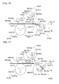
Fig. 14] Fig. 14 is a diagram illustrating a state where a casing and the lid body of the splicing apparatus are detached so as to expose the inside thereof. - [
Fig. 15] Fig. 15 is a diagram illustrating a schematic configuration of the splicing apparatus. - [
Fig. 16] Fig. 16 is a diagram of an actuation state of that inFig. 15 illustrating a step of positioning a cutting place of the carrier tape. - [
Fig. 17] Fig. 17 is a diagram of another actuation state of that inFig. 15 illustrating a step of cutting the carrier tape at the cutting place. - [
Fig. 18] Fig. 18 is a diagram of another actuation state of that inFig. 15 illustrating a step of positioning the carrier tape with respect to a splicing position. - [
Fig. 19] Fig. 19 is a perspective view illustrating a bonding device of the splicing apparatus. - [
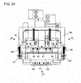
Fig. 20] Fig. 20 is a plan view illustrating the bonding device. - [
Fig. 21] Fig. 21 is a front view seen in an arrow-21 direction ofFig. 20 . - [
Fig. 22] Fig. 22 is a right-side view seen in an arrow-22 direction ofFig. 20 . - [
Fig. 23] Fig. 23 is a left-side view seen in an arrow-23 direction ofFig. 20 . - [
Fig. 24] Fig. 24 is a diagram illustrating a locking device for locking the lid body. - [
Fig. 25] Fig. 25 is a cross-sectional view illustrating a relationship between the carrier tape and the splicing tape at the splicing position. - [
Fig. 26] Figs. 26 (A) to 26 (C) are cross-sectional views taken along line 26-26 inFig. 25 and illustrate actuation states of splicing. - [
Fig. 27] Figs. 27 (A) to 27(D) are diagrams of actuation states illustrating a step of cutting the embossed tape. - Hereinafter, an embodiment of the present invention will be described with reference to the drawings.
Fig. 1 illustrates atape feeder 10 which is detachably mounted in a component supply device of a component mounting machine. Areel 12 having a carrier tape Tc wound therearound is detachably attached to thetape feeder 10. - As illustrated in
Fig. 2 , the carrier tape Tc is formed in an elongated manner having a predetermined width. Multiple cavities Ct are arranged in a longitudinal direction at regular pitch intervals. Components (electronic components) e mounted in a circuit board are respectively accommodated in the cavities Ct. The upper portion of the cavity Ct is open and is covered with a top tape Tt (refer toFig. 3 ) which is pasted on the front face of the carrier tape Tc. - On one end side of the carrier tape Tc in a width direction, sprocket holes Hc are formed at the same pitch intervals as those of the cavities Ct or at pitch intervals twice those of the cavities Ct. The sprocket holes Hc are disposed in regular positional relationships with respect to the cavities Ct.
- The
tape feeder 10 is internally equipped with aquantitative feeding mechanism 18 quantitatively feeding the carrier tape Tc which is wound around thereel 12 and supplying the electronic components e one by one tocomponent supply positions 17 which is provided at the distal end portion of thetape feeder 10. Thequantitative feeding mechanism 18 includes asprocket 19 which is rotatably supported by a main body of thetape feeder 10 and engages with the sprocket holes Hc of the carrier tape Tc, and a motor (not illustrated) for rotating thesprocket 19 by 1 pitch. - The carrier tapes Tc used in the component mounting machine are configured to be in multiple types having the pitch of the cavities Ct different from one another. Depending on the type of the carrier tape Tc, the pitch interval of the cavities Ct and the relationship between the cavity Ct and the sprocket hole Hc are determined. Therefore, as the pitch interval of the cavities Ct is recognized through image processing and the like, it is possible to know the type of the carrier tape Tc. On the basis thereof, the position of the sprocket hole Hc of the carrier tape Tc can be recognized, and thus, a cutting position of the carrier tape Tc at the time of the below-described splicing can be decided.
- A
splicing apparatus 20 is an apparatus which automatically connects a trailing end portion of a carrier tape wound around an existing reel mounted in thetape feeder 10 that is mounted in the component supply device to a leading end portion of a carrier tape wound around a successive reel replacing the existing reel. - As illustrated in
Fig. 6 , thesplicing apparatus 20 includes a box-like casing 21 and alid body 22 which is turnably supported by thecasing 21 centering around a pivot 23 (refer toFig. 24 ) and is used for uncovering and covering the upper face of thecasing 21. Thesplicing apparatus 20 is configured to be loaded on a wheeled table (not illustrated) or the like so as to be movable between thetape feeders 10 mounted in the component supply device of the component mounting machine. Thelid body 22 is placed to cover the upper face when performing splicing and is moved to uncover the upper face when taking the carrier tape Tc out after performing splicing. When thelid body 22 covers the upper face once, the closed state is retained by a locking device described below. - In each of two carrier tapes Tc (hereinafter, referred to as a first carrier tape T1 and a second carrier tape T2) which is spliced by the
splicing apparatus 20, as illustrated inFig. 4 , first cavities Ct1 (second cavities Ct2) accommodating first components e1 (second components e2) which are the components of the same types are provided at a predetermined pitch Pc. - In each of the first and second carrier tapes T1 and T2, first sprocket holes Hc1 (second sprocket holes Hc2) which can mesh with
teeth 67a (67b) of afirst sprocket 61a (asecond sprocket 61b) in a first tape feeding device 50 (a second tape feeding device 51) described below are bored to be parallel to the first cavities Ct1 (the second cavities Ct2) at a predetermined pitch Ph. - The first and second carrier tapes T1 and T2 are cut at arbitrary first and second cutting places Q1 and Q2 by the
splicing apparatus 20, and the cut ends thereof are caused to abut each other, thereby being connected to each other by asplicing tape 30 described below. For example, as the first cutting place Q1 (the second cutting place Q2), an intermediate position between the first cavity Ct1 (the second cavity Ct2) including the first component e1 (the second component e2) and the first vacant cavity Ct1 (the second vacant cavity Ct2) including no first component e1 (no second component e2) is selected. - The first carrier tape T1 (the second carrier tape T2) including the continuous first vacant cavities Ct1 (the continuous second vacant cavities Ct2) after being cut is discarded as a first unnecessary portion Tf1 (a second unnecessary portion Tf2). In order to secure the first vacant cavities Ct1 (the second vacant cavities Ct2) in the arbitrary numbers, an intermediate position between the first vacant cavities Ct1 (the second vacant cavities Ct2) which are adjacent to each other can be selected as the first cutting place Q1 (the second cutting place Q2).
- As the carrier tapes T1 and T2, there is an embossed tape T1e (T2e) of which the pitch Pc of the cavities Ct1 (Ct2) are different from each other, or in which the cavities (embossed portions) Cte1 (Cte2) protrude in a thickness direction as illustrated in
Fig. 5 . The different types of the carrier tapes can also be connected by thesplicing apparatus 20. - In the
splicing apparatus 20, the two carrier tapes T1 and T2 to be spliced are fed from the right and left inFig. 7 , and a protection tape 31 (refer toFig. 8 ) having the splicingtape 30 which connects the two carrier tapes T1 and T2 to each other pasted therein is fed from above, that is, orthogonal to the right and left inFig. 7 . Then, as illustrated inFig. 8 , end portions of the two carrier tapes T1 and T2 are connected to each other by thesplicing tape 30 at a splicing position LS where the carrier tapes T1 and T2 intersect with theprotection tape 31. - The
splicing tape 30 pasted on theprotection tape 31 is fed into the splicing position LS causing a glue face between the carrier tapes T1 and T2 to face upward, and the two carrier tapes T1 and T2 are positioned above thesplicing tape 30. - As illustrated in
Fig. 10 , on the upper face of thecontinuous protection tape 31, thesplicing tape 30 is configured to include one set ofsplicing tapes splicing tape 30 is configured to form one set including the frontface splicing tape 30a which is bonded onto the front face sides of the two carrier tapes T1 and T2 and the rearface splicing tape 30b which is bonded onto the rear face sides of the two carrier tapes T1 and T2. - The one set of the
splicing tapes 30 for the front face and the rear face is pasted on theprotection tape 31 in the longitudinal direction at regular pitch intervals Pd while maintaining a regular positional relationship with respect to feedingholes 31a which are bored on both the sides of theprotection tape 31 at regular pitch intervals. The one set of thesplicing tapes face splicing tape 30a to be the leading side, and the rearface splicing tape 30b and the successive frontface splicing tape 30a are disposed at predetermined intervals Pd2 (Pd2 = Pd - Pd1). Then, metal powder is embedded in the one set of thesplicing tapes metal detection sensors - As illustrated in
Figs. 10 and11 , twometal detection sensors splicing tapes protection tape 31 at predetermined intervals. Specifically, when the one set of the splicing tapes for the front face and the rear face (first splicing tapes) 30 are positioned at the splicing position LS, the twometal detection sensors metal detection sensors face splicing tape 30a of the successive one set of the splicing tapes (second splicing tapes) 30 and the rearface splicing tape 30b of the next successive one set of the splicing tapes (third splicing tapes). In states other than those thereof, the twometal detection sensors Figs. 13 (B) to 13(E) ). - The upper faces of the
splicing tapes Fig. 9 , acontinuous paper mount 32 is glued onto the glue face thereof. A three-layer structure body including thepaper mount 32, thesplicing tape 30, and theprotection tape 31 is wound around asupply reel 33 in a rolled manner. - The measurement of the
protection tape 31 in the width direction is greater than the measurement of thepaper mount 32 in the width direction, and both ends of theprotection tape 31 in the width direction protrude further than both ends of thepaper mount 32 in the width direction. Meanwhile, the measurement of thesplicing tape 30 in the width direction is equivalent to the measurement of thepaper mount 32 in the width direction, and thesplicing tape 30 is pasted on theprotection tape 31 forming one set with the splicing tapes for the front face and the rear face on the inner side of thefeeding hole 31a. - As illustrated in
Fig. 10 , a plurality ofpositioning holes 31b are formed in theprotection tape 31 along theprotection tape 31 in the width direction at the same pitch intervals as those of the sprocket holes Hc1 and Hc2 which are formed in the carrier tapes T1 and T2 at a position near the frontface splicing tape 30a. A plurality of positioning holes 30b1 are formed so as to penetrate theprotection tape 31 in the rearface splicing tape 30b along theprotection tape 31 in the width direction at the same pitch intervals as those of the sprocket holes Hc1 and Hc2 which are formed in the carrier tapes T1 and T2. - The feeding holes 31a and the
positioning holes 31b formed in theprotection tape 31 are formed through punching-pressing in association with forming of the positioning holes 30b1 performed in thesplicing tape 30b after thesplicing tapes protection tape 31 at a predetermined position. - As illustrated in
Fig. 8 , in thesplicing apparatus 20, therotatable supply reel 33 around which the three-layer structure body including thesplicing tape 30 is wound in a rolled manner, a papermount feeding device 35 which feeds thepaper mount 32 caused to peel off from thesplicing tape 30, and a protectiontape feeding device 36 which feeds theprotection tape 31 from which thesplicing tape 30 peels off are arranged on a line crossing the splicing position LS where the two carrier tapes T1 and T2 are spliced. - Regarding a glue force of the
splicing tapes 30 with respect to thepaper mount 32 and theprotection tape 31 which are glued onto both faces of thesplicing tapes 30, the glue force with respect to theprotection tape 31 is stronger than the other. Therefore, even though thepaper mount 32 is caused to peel off from thesplicing tape 30, thesplicing tape 30 is prevented from peeling off from theprotection tape 31. - However, if the carrier tapes T1 and T2 are glued onto the glue face of the
splicing tape 30 from which thepaper mount 32 is peeled off, the adhesive force thereof is stronger than the adhesive force with respect to theprotection tape 31. Therefore, theprotection tape 31 is likely to peel off from thesplicing tape 30. - The three-layer structure body including the
paper mount 32, thesplicing tape 30, and theprotection tape 31 is mounted in thesplicing apparatus 20 in a state of being wound around thesupply reel 33, and the distal end thereof is drawn out from thesupply reel 33. Then, a worker peels off and folds back thepaper mount 32 to, and thepaper mount 32 is fed by the papermount feeding device 35 and is discarded into a paper mount accommodation box (not illustrated). - The
protection tape 31 from which thepaper mount 32 is peeled off, that is, theprotection tape 31 in whichmultiple splicing tapes 30 are pasted with the glue face thereof facing upward passes through the below-describedbonding device 58 so as to cross the center of the splicing position LS, and thus, the distal end portion of theprotection tape 31 engages with a feeding sprocket 46 (refer toFig. 12 ) of the protectiontape feeding device 36. - As illustrated in
Fig. 12 , in the feedingsprocket 46, theprotection tape 31 which engages with theengagement teeth 46a is fed by a unit quantity by forming a plurality ofengagement teeth 46a at equiangular intervals in a circumferential direction at the same pitch as the pitch of the feeding holes 31a bored in theprotection tape 31 and driving a steppingmotor 47 connected to the feedingsprocket 46 by one pitch. The steppingmotor 47 returns to the original position as power is supplied, and anengagement teeth 46a of the feedingsprocket 46 is positioned so as to be at the apex at all times. - As the protection tape 31 (the splicing tape 30) is fed by a unit quantity ΔPd as illustrated in
Figs. 13 (A) to 13 (F) in accordance with the steppingmotor 47 driven by one pitch and the feeding thereof is repeated N times (for example, 5 times), theprotection tape 31 is fed by only the pitch Pd of one set of thesplicing tapes 30, and thus, one set of thesplicing tapes 30 for the front face and the rear face is sequentially conveyed to the splicing position LS. - As illustrated in
Fig. 7 , thesplicing apparatus 20 includes the first and secondtape feeding devices component detection devices second cutting devices devices bonding device 58, and a control device 59 (refer toFig. 6 ). The first and secondtape feeding devices second cutting devices devices control device 59 are accommodated and disposed inside thecasing 21 covered with thelid body 22. - In other words, as illustrated in
Fig. 14 , the first and secondtape feeding devices casing 21 covered with thelid body 22. The first andsecond cutting devices tape feeding devices devices second cutting devices bonding device 58 is disposed between the first and second take-indevices component detection devices second conveyance paths tape feeding devices - The first and second
tape feeding devices second conveyance paths casing 21 toward the center in a horizontal direction, the first andsecond sprockets second conveyance paths second stepping motors second sprockets tooth detection devices second sprockets tape detection devices second conveyance paths - The first and second
tape feeding devices second conveyance paths Fig. 4 ) of the first and second carrier tapes T1 and T2 sequentially at first and second cutting positions Lc1 and Lc2, and the splicing position LS. - The first and
second conveyance paths casing 21 to the first and second cutting positions Lc1 and Lc2 of the first and second carrier tapes T1 and T2 which are cut by first andsecond cutters second cutting devices - In addition, as illustrated in the enlarged view A in
Fig. 7 (only thesecond conveyance path 60b is illustrated, but thefirst conveyance path 60a is the same as well), first and secondmicro grooves second conveyance paths - In other words, first and
second leaf springs micro grooves second leaf springs second leaf springs - A plurality of the first and
second teeth second sprockets second sprockets second conveyance paths second conveyance paths - The first and second sprocket
tooth detection devices second sprockets second sprockets - The first and second
tape detection devices casing 21. - The first and second
component detection devices second conveyance paths - As illustrated in
Figs. 14 and 15 , the first andsecond cutting devices second cutters second cams second cutters second gear motors second cams second cutters lid body 22, first and secondpressing members second cutters pressing springs second cutters pressing members cutter detection devices second cutters - The first and
second cutting devices Fig. 17 ) in the first and second cutting places Q1 and Q2 of the first and second carrier tapes T1 and T2. - In order to cut the first and second cutting places Q1 and Q2 of the first and second carrier tapes T1 and T2 which are positioned at the first and second cutting positions Lc1 and Lc2, the first and
second cutters second cams - In order to press and fix the vicinity of the first and second cutting places Q1 and Q2 of the first and second carrier tapes T1 and T2 which are positioned at the first and second cutting positions Lc1 and Lc2, the first and second
pressing members pressing springs - The first and second take-in
devices members second fixing members member turning devices members devices - First and
second openings second conveyance paths second ducts members - While the first and second unnecessary portions Tf1 and Tf2 are taken in, the first and second take-in
members Fig. 15 . When the first and second carrier tapes T1 and T2 are conveyed to the splicing position Ls, as indicated by the solid line inFig. 15 , the first and second take-inmember turning devices members movable conveyance paths members second conveyance paths - The
bonding device 58 is provided between thefirst cutting device 54 and thesecond cutting device 55. Thebonding device 58 is configured to be able to connect the first and second carrier tapes T1 and T2 to each other at the splicing position LS in the middle of the first andsecond conveyance paths splicing tape 30. - Subsequently, the configuration of the
bonding device 58 will be described with reference toFigs. 19 to 23 . Thebonding device 58 includes a first lifting and lowering table 91, apressing plate 97, a second lifting and lowering table 101, a swivel table 103, and the like.Leg portions 92 of the first lifting and lowering table 91 are guided and supported by thecasing 21 so as to be able to be lifted and lowered. On the first lifting and lowering table 91, two for each of first positioning pins 93 and 94 which can engage with the positioning holes 30b1 formed in thesplicing tape 30b, and each of the sprocket holes Hc of the two carrier tapes T1 and T2 are provided protruding along the carrier tapes T1 and T2 in a feeding direction on both the sides having a bonding position (an abutting position) of the two carrier tapes T1 and T2 as the center. Each pitch of the two sets of the first positioning pins 93 and 94 is set to be twice the pitch P of the sprocket holes Hc in the carrier tapes T1 and T2. - In the first lifting and lowering table 91, a
pin hole 95 is formed between each set of the first positioning pins 93 and 94, and second positioning pins 105 on the below-described swivel table 103 side can be inserted into the pin holes 95. - A movable table 96 is movably guided and supported by the
casing 21 in the horizontal direction orthogonal to the longitudinal direction of the carrier tapes T1 and T2. Thepressing plate 97 is attached to the movable table 96 at a position above the first positioning pins 93 and 94.U-shaped grooves 98 which can accommodate the first positioning pins 93 and 94 are formed at the distal end of thepressing plate 97. Thepressing plate 97 can move forward and rearward between positions of a rearward movement end at which thegrooves 98 escape from the first positioning pins 93 and 94 and a forward movement end at which thegrooves 98 accommodate the first positioning pins 93 and 94. - Moreover,
leg portions 102 of the second lifting and lowering table 101 are guided and supported by thecasing 21 so as to be able to be lifted and lowered. On the second lifting and lowering table 101, both ends of the swivel table 103 are supported having apivot shaft 104 which is parallel to the longitudinal direction of the carrier tapes T1 and T2 as the swivel center, so as to be swivelable 180 degrees. Apressing plate 103a is provided in the swivel table 103 at a position offset from the swivel center. A plurality of the second positioning pins 105 and pin holes 106 are provided in thepressing plate 103a. Each of the second positioning pins 105 is arranged at a position corresponding to the middle of the first positioning pins 93 and 94 which are provided on the first lifting and lowering table 91, and is able to be inserted into thepin hole 95 which is provided in the first lifting and lowering table 91. Moreover, each of the pin holes 106 is arranged at a position corresponding to the middle of the second positioning pins 105, and the first positioning pins 93 and 94 which are provided on the first lifting and lowering table 91 can be inserted therein. - As the swivel table 103 swivels 180 degrees, the second positioning pins 105 engage with the sprocket holes Hc of the two carrier tapes T1 and T2 which are positioned at the splicing position LS and the positioning holes 30b1 of the
splicing tape 30b so that positional relationships are regularly maintained among the three, that is, the two carrier tapes T1 and T2 and thesplicing tape 30 which connects the two carrier tapes T1 and T2 to each other. -
Pinions 107 are attached to thepivot shaft 104 of the swivel table 103, and racks 108 which mesh with thepinions 107 are attached to a movable table 109 which is movable in the horizontal direction orthogonal to a conveyance direction of the carrier tapes T1 and T2. Accordingly, as the movable table 109 moves, the swivel table 103 is caused to swivel by rack and pinion mechanisms each of which includes thepinion 107 and therack 108. - As the swivel table 103 swivels, the three of the two carrier tapes T1 and T2 and the
splicing tape 30 are pinched between thepressing plate 103a and the first lifting and lowering table 91, thereby being connected to one another. - As illustrated in
Fig. 19 andFig. 26 , sufficientlyelastic rubber sheets pressing plate 103a. Therubber sheets splicing tape 30, regardless of whether the type of the carrier tape to be spliced is the paper tape or the embossed tape. - In other words, the
rubber sheet 121 attached to the first lifting and lowering table 91 includes astep difference 121a which is formed by lowering a side provided with the cavities Ct1 and Ct2 with respect to a side provided with the sprocket holes Hc1 and Hc2 of the carrier tapes T1 and T2. In contrast, as illustrated inFig. 26(B) , therubber sheet 122 attached to thepressing plate 103a includes astep difference 122a which is formed by raising a side provided with the cavities Ct1 and Ct2 with respect to a side provided with the sprocket holes Hc1 and Hc2. Then, as illustrated inFig. 26(A) , in step difference amounts d1 and d2 of both therubber sheets rubber sheet 122 attached to thepressing plate 103a is caused to be greater than the other (d1 < d2). - The aforementioned configuration is made in order to reliably glue the
splicing tape 30 onto the irregular face as well, since the embossed tape has the flat front face and the rear face which includes the irregularly protruding cavities Ct1 and Ct2, compared to the paper tape in which both the front face and the rear face are flat faces. - Accordingly, as described below, when the carrier tapes T1 and T2 (the paper tapes) are pinched by the first lifting and lowering table 91 and each of the
rubber sheets pressing plate 103a, the higher step difference portion of the rubber tape is deformed and thesplicing tape 30 is bonded onto the carrier tapes T1 and T2. In contrast, when the carrier tapes T1 and T2 (the embossed tapes) are pinched by the first lifting and lowering table 91 and each of the rubber sheets of thepressing plate 103a, since the cavities Ct1 and Ct2 can be accommodated in the lower step difference portion of therubber sheet 121 on the first lifting and lowering table 91, thesplicing tape 30 can be bonded without adding excessive pressure to the cavities Ct1 and Ct2. Moreover, since therubber sheet 122 attached to thepressing plate 103a is caused to be greater than the other regarding step difference between both therubber sheets - A
cam drum 110 is rotatably supported in thecasing 21 around the axial line which is parallel to the swivel center of the swivel table 103, thereby rotating slowly in a regular direction by a drive motor (not illustrated). On both the faces of thecam drum 110, two sets of inner andouter cam grooves - A first follower roller (not illustrated) which is pivotally supported by the
leg portions 92 of the first lifting and lowering table 91 engages with thefirst cam groove 110a. A second follower roller (not illustrated) which is pivotally supported by the movable table 96 connected to thepressing plate 97 engages with thesecond cam groove 110b. A third follower roller (not illustrated) which is pivotally supported by theleg portions 102 of the second lifting and lowering table 101 engages with thethird cam groove 110c. A fourth follower roller (not illustrated) which is pivotally supported by a connection member 112 connected to the movable table 109 engages with thefourth cam groove 110d. - In this manner, as the
cam drum 110 rotates, a lifting and lowering motion of each of the first and second lifting and lowering tables 91 and 101, a forward and rearward motion of thepressing plate 97, and a swivel motion of the swivel table 103 are inter-connectedly performed through the first to fourth follower rollers which respectively engage with the first tofourth cam grooves 110a to 110d. The first and second lifting and lowering tables 91 and 101, thepressing plate 97, and the swivel table 103 return to the original positions with one rotation of thecam drum 110. - As illustrated in
Fig. 24 , thesplicing apparatus 20 is provided with alocking device 24 which locks thelid body 22 in a closed state during a splicing operation. The lockingdevice 24 is mainly configured to include asolenoid 25 which is installed in thecasing 21 and is able to actuate anactuation rod 25a in the vertical direction, ahook 27 which is turnably supported by thecasing 21 centering around apivot 26 and is caused to turn by thesolenoid 25, and anengagement pin 28 which is provided in thelid body 22 so as to protrude downward and disengageably engages with thehook 27. - An
opening spring 29 which biases thelid body 22 in an opening direction is provided between thecasing 21 and thelid body 22. When thehook 27 is caused to disengage from theengagement pin 28, thelid body 22 is automatically moved by theopening spring 29 so as to uncover the inside. A dog (not illustrated) is provided in thelid body 22, and thecasing 21 is provided with a closed-state confirmation sensor which is operated by the dog. The closed-state confirmation sensor is operated by the dog when covering the inside with thelid body 22, and a closed state of thelid body 22 is confirmed based on an ON signal of the closed-state confirmation sensor. - Then, when the
lid body 22 is placed to cover the inside by a worker and the closed-state confirmation sensor is turned on by the dog, theactuation rod 25a of thesolenoid 25 is actuated in the upward direction ofFig. 23 and thehook 27 is caused to turn so as to engage with theengagement pin 28, based on the ON signal. Accordingly, thelid body 22 is locked in a closed state by the lockingdevice 24. - When the two carrier tapes T1 and T2 are connected to each other by the
splicing tape 30 and a connection completion signal is issued by thecontrol device 59, theactuation rod 25a of thesolenoid 25 is actuated in the downward direction ofFig. 23 . Accordingly, thehook 27 is caused to turn so as to disengage from theengagement pin 28, and thelid body 22 is automatically moved to uncover the inside due to a biasing force of theopening spring 29. - Subsequently, an operation of the
splicing apparatus 20 according to the above-described embodiment will be described. When the remaining quantity of the components e retained in the first carrier tape T1 which is attached to thetape feeder 10 wound around thereel 12 decreases, splicing processing for causing the leading end portion of the second carrier tape T2 which is wound around another reel accommodating the same types of the components e to be connected to the trailing end portion of the first carrier tape T1 is executed by thesplicing tape 30. The components can be reloaded through such splicing processing, and thus, thetape feeder 10 can continue to supply the components. - In such splicing processing, so-called verifying of splicing processing is generally executed in order to check whether or not the carrier tape accommodating the right components is connected thereto. In verifying of splicing processing, a barcode labelled on an old reel is read by a barcode reader, and the serial ID of the components accommodated in the old reel is transmitted to a management computer. Subsequently, a barcode labelled on a new reel is read by the barcode reader, and the serial ID of the components accommodated in the new reel is transmitted to the management computer.
- Since data related to the component is stored in the database of the management computer for each serial ID, it is possible to verify whether or not the components accommodated in the two carrier tapes T1 and T2 are the same types by the read serial IDs. If the components are inconsistent with each other, a verification error is displayed on an operation panel and an operator is notified, and thus, the operator restarts splicing processing based thereon.
- When verifying of splicing processing is completed, each end portion of the two carrier tapes T1 and T2 is cut with scissors. At this time, generally, since a vacant cavity portion having no component accommodated therein is provided at the end portion of each of the carrier tapes T1 and T2 to the extent of several tens of millimeters, the portion is cut by a worker. In this case, as is obvious from the following description, since the cut faces are not the abutting faces of the two carrier tapes T1 and T2, accuracy is not particularly required.
- Generally, the
lid body 22 is placed to cover the inside thereof. When a worker turns the power on in the state thereof, thecontrol device 59 causes thestepping motors tooth detection devices control device 59 detects whether or not the distal end portions of the first and second tapes T2 are inserted from the first and second tape entrances 84a and 84b, based on detection signals from the first and secondtape detection devices motors second sprockets members - Subsequently, the
control device 59 sequentially detects the first vacant cavities Ct1 and Ct2, and the second vacant cavities Ct1 and Ct2 which do not include the components e1 and e2 in the first and second tapes T1 and T2, based on detection signals from the first and secondtape detection devices - Subsequently, the
control device 59 calculates the cutting places Q1 and Q2 (refer toFig. 4 ) of the first and second tapes T1 and T2 based on the pitch Pc between the cavities Ct1 and Ct2, and distances D1 and D2 between the known detection positions L d1 and L d2 and the known cutting positions Lc1 and Lc2. Then, as illustrated inFig. 16 , the first and second tapes T1 and T2 are moved by the distances D1 and D2, and the unnecessary portions Tf1 and Tf2 are taken in the first and second take-inmembers - In this manner, when conveying and positioning of the first and second carrier tapes T1 and T2 are completed, the
control device 59 causes each of thecutters pressing members pressing members cutters ducts members - As the first and second carrier tapes T1 and T2 are cut by the
cutters control device 59 causes the take-inmembers sprockets motors bonding device 58 provided at the splicing position LS. - The above-described first and second
tape feeding devices - In this manner, the distal ends of the first and second carrier tapes T1 and T2 inserted from the first and second tape entrances 84a and 84b are positioned at the splicing position LS without causing a misaligned pitch.
- Meanwhile, the three-layer structure body including the
paper mount 32, thesplicing tape 30, and theprotection tape 31 wound around thesupply reel 33 is drawn out from thesupply reel 33, and thepaper mount 32 is peeled off, thereby being fed by the papermount feeding device 35. Theprotection tape 31 having the splicingtape 30 pasted thereto is fed by the protectiontape feeding device 36, and thus, one set of thesplicing tapes 30 for the front face and the rear face is conveyed to the splicing position LS. - In other words, as the stepping
motor 47 of the protectiontape feeding device 36 feeds thesplicing tape 30 by the unit quantity ΔPd as illustrated inFig. 13 and the feeding thereof is repeated N times (5 times in the embodiment), one set of thesplicing tapes 30 for the front face and the rear face is fed by only the pitch Pd, thereby being conveyed to the splicing position LS, as illustrated inFig. 13(F) . - As one set of the
splicing tapes 30 for the front face and the rear face is conveyed to the splicing position LS, one side of the successive one set of thesplicing tapes 30, that is, the frontface splicing tape 30a is detected by the firstmetal detection sensor 48, and at the same time, the rearface splicing tape 30b of the next successive one set of thesplicing tapes 30 is detected by the secondmetal detection sensor 49. Accordingly, it is possible to confirm that the one set of thesplicing tapes 30 for the front face and the rear face is properly positioned at the splicing position LS, and thus, it is possible to reliably prevent the frontface splicing tape 30a and the rearface splicing tape 30b from being positioned at the splicing position LS in a reverse disposition. - In this manner, when the
splicing tape 30 is positioned at the splicing position where the first and secondmetal detection sensors face splicing tape 30b can engage with the first positioning pins 93 and 94 of thebonding device 58 provided at the splicing position LS (refer toFig. 25 ). When thesplicing tape 30 is positioned at the splicing position LS, if the first and second carrier tapes T1 and T2 are not positioned at the splicing position LS, thesplicing tape 30 is on standby until the first and second carrier tapes T1 and T2 are positioned at the splicing position LS. - As each of the first and second carrier tapes T1 and T2, and the
splicing tape 30 is positioned at the splicing position LS, the drive motor (not illustrated) rotates thecam drum 110. Firstly, in accordance with rotations of thecam drum 110, the first lifting and lowering table 91 rises through the first follower roller (not illustrated) which engages with thefirst cam groove 110a. - As the first lifting and lowering table 91 rises, the first positioning pins 93 and 94 respectively engage with the positioning holes 30b1 in the rear
face splicing tape 30b and each of the sprocket holes Hc in the two carrier tapes T1 and T2. At this time, as illustrated inFig. 26(A) , since thepressing plate 97 is interposed between the rearface splicing tape 30b and each of the carrier tapes T1 and T2, the carrier tapes T1 and T2 are not glued onto the rearface splicing tape 30b. Accordingly, the positional relationships among the three, that is, the two carrier tapes T1 and T2 and the rearface splicing tape 30b which is glued onto the rear face sides of the two carrier tapes T1 and T2 can be regularly maintained. - Subsequently, the movable table 96 moves in the horizontal direction through the second follower roller (not illustrated) which engages with the
second cam groove 110b. Thepressing plate 97 which is interposed between the rearface splicing tape 30b and the carrier tapes T1 and T2 moves rearward with respect to the first lifting and lowering table 91. Thus, the rearface splicing tape 30b can be glued onto the carrier tapes T1 and T2. - Subsequently, the movable table 109 moves horizontally through the third follower roller (not illustrated) which engages with the
third cam groove 110c. In accordance with the horizontal movement of the movable table 109, the swivel table 103 swivels in the clockwise direction ofFig. 22 by the rack and pinion mechanism (107 and 108). In accordance with swiveling of the swivel table 103, as illustrated inFig. 26(B) , theprotection tape 31 engaging with the second positioning pins 105 is bent, and the frontface splicing tape 30a is turned over with the glue face facing downward at a position above the carrier tapes T1 and T2. In other words, theprotection tape 31 is bent so as to clamp the carrier tapes T1 and T2 therebetween. Then, the rearface splicing tape 30b is positioned on the rear face sides of the carrier tapes T1 and T2, and the frontface splicing tape 30a is positioned on the front face sides of the carrier tapes T1 and T2. At this time, the motor of the protectiontape feeding device 36 rotates reversely so as to impart slackness to theprotection tape 31, thereby allowing theprotection tape 31 to be bent. - Successively, the second lifting and lowering table 101 is lowered through the fourth follower roller (not illustrated) which engages with the
fourth cam groove 110d. As the second lifting and lowering table 101 is lowered, as illustrated inFig. 26(C) , the second positioning pins 105 engage with the positioning holes 31b of theprotection tape 31, the sprocket holes Hc of the carrier tapes T1 and T2, and the positioning holes 30b1 of the rearface splicing tape 30b from the rear side of theprotection tape 31. - Moreover, as the second lifting and lowering table 101 is lowered, in a state of pinching the carrier tapes T1 and T2, the
bent protection tape 31 is pressed between thepressing plate 103a of the swivel table 103 and the first lifting and lowering table 91. Due to the pressing, the rearface splicing tape 30b pasted on theprotection tape 31 is glued across the rear faces of the carrier tapes T1 and T2, and the frontface splicing tape 30a is glued across each of the top tapes Tt which are pasted on the front faces of the carrier tapes T1 and T2. Thus, the trailing end portion of the first carrier tape T1 and the leading end portion of the second carrier tape T2 are connected to each other. The pressed state lasts for a certain time (for several seconds). - In this case, the
pressing plate 103a and the first lifting and lowering table 91 are provided with therubber sheets step differences rubber sheets - Since the two carrier tapes T1 and T2 are connected by the
splicing tape 30 in a state where the carrier tapes T1 and T2 and thesplicing tapes - Bonding of the two carrier tapes T1 and T2 performed by the
splicing tape 30 is achieved in accordance with the 180-degree rotation of thecam drum 110, and each of the constituting members return to the original position in accordance with the remaining 180-degree rotation due to an operation opposite to that described above. - In other words, the second lifting and lowering table 101 rises first, and the swivel table 103 rises with respect to the first lifting and lowering table 91. Then, the pressed state of the
bent protection tape 31 is released, and the second positioning pins 105 escape from the positioning holes 30b1 of the rearface splicing tape 30b and each of the sprocket holes Hc of the two carrier tapes T1 and T2. In this case, since thesplicing tape 30 has high adhesiveness with respect to the carrier tapes T1 and T2, theprotection tape 31 easily peels off from thesplicing tape 30 due to a returning force of the spring of theprotection tape 31 generated by releasing the pressed state of theprotection tape 31, and thus, thesplicing tape 30 is not peeled off from the carrier tapes T1 and T2. - Successively, the swivel table 103 swivels in the counterclockwise direction of
Fig. 21 through the rack and pinion mechanism (108 and 107), and the motor of the protectiontape feeding device 36 rotates forward, thereby eliminating the slackness of theprotection tape 31. - Thereafter, the
pressing plate 97 moves forward, and the first lifting and lowering table 91 is lowered. Then, the first positioning pins 93 and 94 escape from the positioning holes 30b1 of the rearface splicing tape 30b and each of the sprocket holes Hc of the two carrier tapes T1 and T2. Meanwhile, the motor is driven in the papermount feeding device 35 so as to apply tension to thepaper mount 32, and thus, thepaper mount 32 is peeled off as much as necessary. In this manner, bonding between the trailing end portion of the first carrier tape T1 and the leading end portion of the second carrier tape T2 is completed. - In this manner, as the two carrier tapes T1 and T2 are connected to each other by the
splicing tape 30, a connection completion signal is issued by thecontrol device 59. Based on the connection completion signal, thesolenoid 25 of thesplicing apparatus 20 is actuated, theactuation rod 25a moves downward, and thehook 27 turns in the clockwise direction ofFig. 24 centering around thepivot 26. Accordingly, thehook 27 and theengagement pin 28 are disengaged from each other, and thelid body 22 turns centering around thepivot 23 by the biasing force of thespring 29, thereby automatically uncovering the inside thereof. In such a state, the first and second spliced carrier tapes T1 and T2 are taken out from thesplicing apparatus 20 by a worker. - Thereafter, the
reel 12 having the second carrier tape T2 wound therearound is set to thetape feeder 10, thereby completing splicing processing. In this manner, thetape feeder 10 is reloaded with the components, and thus, mounting of the components can be continuously carried out in the component mounting machine without stopping the machine. - When the
lid body 22 is placed to cover the inside by a worker in order to splice another carrier tape, the closed-state confirmation sensor (not illustrated) is turned on by the dog which is fixed onto thelid body 22. Based on the ON signal of the closed-state confirmation sensor, thesolenoid 25 is actuated, and theactuation rod 25a moves upward. Accordingly, thehook 27 turns in the counterclockwise direction ofFig. 24 centering around thepivot 26, thereby engaging with theengagement pin 28 fixed onto thelid body 22. At the same time, an actuation confirmation sensor (not illustrated) is turned on by the dog (not illustrated) attached to thehook 27. As both the closed-state confirmation sensor and the actuation confirmation sensor are turned on, thesplicing apparatus 20 can be automatically operated. - In this manner, when the
lid body 22 is placed to cover the inside, thelid body 22 cannot be in an open state by an external force. Thus, it is possible to prevent the operation section inside thesplicing apparatus 20 from being in contact with a worker during an automatic operation, and to ensure safety. In addition, when splicing is completed, thelid body 22 is automatically moved so as to uncover the inside. Thus, it is possible to enhance workability. - The
splicing apparatus 20 is provided with an operation button (not illustrated) which unlocks the locked state in case of an emergency stop. An automatic operation is stopped by operating the operation button during the automatic operation of thesplicing apparatus 20 so that thelid body 22 can be manually moved to uncover the inside. In this case, the automatic operation cannot be performed unless thelid body 22 is placed to cover the inside and locked again. - As described above, the stepping
motor 47 feeds the splicing tape 30 N times by the unit quantity ΔPd as illustrated inFig. 13 , and thesplicing tape 30 is positioned at the splicing position LS where the first and secondmetal detection sensors bonding device 58. - When the
lid body 22 of thesplicing apparatus 20 is placed to cover the inside and power is supplied, the steppingmotor 47 returns to the original position (theengagement tooth 46a of the feedingsprocket 46 is positioned at the apex), and in such a state, the steppingmotor 47 intermittently feeds thesplicing tape 30 by the unit quantity ΔPd. Accordingly, even though the position of the steppingmotor 47 is misaligned while thesplicing apparatus 20 is halted, thefirst splicing tape 30 which is pasted on the forefront of theprotection tape 31 can be accurately positioned at the splicing position where the first and secondmetal detection sensors - When the first and second
metal detection sensors metal detection sensor 48 is turned on) even though the steppingmotor 47 feeds the splicing tape 30 N times by the unit quantity ΔPd, a splicing tape disconnection signal is issued by thecontrol device 59. In this manner, disconnection of thesplicing tape 30 can be detected by the first and secondmetal detection sensors new protection tape 31. - Then, when a
new protection tape 31 is set to thesplicing apparatus 20, as the steppingmotor 47 intermittently feeds thesplicing tape 30 by the unit quantity ΔPd, the first and secondmetal detection sensors metal detection sensors first splicing tape 30 which is pasted on the forefront of theprotection tape 31 is positioned at the splicing position LS. - In the example described above, two of the carrier tapes T1 and T2 (paper tapes) having both the front face and the rear face to be flat are spliced. However, in a case where the first and second carrier tapes T1 and T2 are the embossed tapes T1e and T2e as illustrated in
Fig. 5 , when being conveyed along the first andsecond conveyance paths Fig. 27(A) , the first and second cavities Cte1 and Cte2 are conveyed along the inside of the first and secondmicro grooves second leaf springs Fig. 27(B) ). - Then, when the first and
second cutters pressing members pressing members second leaf springs micro grooves Fig. 27(C) ). Accordingly, the first and second cutting places Q1 and Q2 of the first and second embossed tapes T1e and T2e are positioned at the first and second cutting positions Lc1 and Lc2 with high accuracy, and thus, it is possible to enhance cutting accuracy of the first and second embossed tapes T1e and T2e. - Then, when the first and
second cutters pressing members second leaf springs micro grooves Fig. 27(D) ). Accordingly, the first and second cavities Cte1 and Cte2 can get on the first andsecond leaf springs - When the embossed tapes T1e and T2e are positioned at the splicing position LS, the cavities Cte1 and Cte2 of the embossed tapes T1e and T2e are accommodated at the lower step difference portion of the
rubber sheet 121 which is attached to the first lifting and lowering table 91. Therefore, thesplicing tapes rubber sheets - Moreover, since a difference is provided between the step difference of the
rubber sheet 121 which is attached to the first lifting and lowering table 91 and the step difference of therubber sheet 122 which is attached to thepressing plate 103a (d1 < d2), when the embossed tapes T1e and T2e are pinched between therubber sheets splicing tape 30 can be reliably bonded onto such embossed tapes T1e and T2e having irregularities. - According to the above-described embodiment, the embodiment includes the first and second tape feeding devices (the positioning devices) 50 and 51 that feed the first and second carrier tapes T1 and T2 in a direction approaching each other and cause the positioning pins 93 and 94 to be positioned at the splicing position LS so as to be able to engage with the sprocket holes Hc1 and Hc2 of the first and second carrier tapes T1 and T2, the plurality of a set of the splicing tapes 30 (30a and 30b) for the front face and the rear face that is pasted at the splicing position LS on the
continuous protection tape 31 fed in a direction orthogonal to the feeding direction of the first and second carrier tapes T1 and T2 and has metal embedded therein, a pair of themetal detection sensors protection tape 31 and detects thesplicing tape 30, and thebonding device 58 that bonds thesplicing tapes splicing tapes protection tape 31, and the pair of themetal detection sensors splicing tapes - According to the above-described configuration, it is possible to easily detect that the one set of the
splicing tapes metal detection sensors splicing tapes face splicing tape 30a and the rearface splicing tape 30b to be reversely disposed, and thus, it is possible to acquire thesplicing apparatus 20 which can perform highly accurate splicing. - According to the above-described configuration, as the
protection tape 31 is fed N times by the unit quantity in accordance with rotations of thesprocket 46 which engages with thefeeding holes 31a formed at both ends of theprotection tape 31 in the width direction, thesplicing tapes metal detection sensors protection tape 31 can be enhanced based on a rotation amount of thesprocket 46, and thesplicing tapes protection tape 31. - According to the above-described configuration, since the
rubber sheets pressing plate 103a in which the first and second carrier tapes T1 and T2 and thesplicing tapes splicing tapes splicing tapes rubber sheet 121 without adding an excessive force to the cavities Cte1 and Cte2 of the embossed tapes T1e and T2e. - Moreover, even though both the front face and the rear face of the first and second carrier tapes T1 and T2 are flat as those of the paper tape, the
rubber sheets rubber sheets - According to the above-described configuration, the
lid body 22 is locked by the lockingdevice 24 so that thelid body 22 cannot be in an open state by an external force. Therefore, it is possible to prevent the operation section inside thesplicing apparatus 20 from being in contact with a worker during an automatic operation, and to ensure safety. In addition, when splicing is completed, thelid body 22 can be automatically moved so as to uncover the inside. Thus, it is possible to enhance workability. - According to the above-described embodiment, descriptions are given regarding an example in which metal is embedded in the
splicing tapes splicing tapes metal detection sensors - According to the above-described embodiment, descriptions are given regarding the three-layer structure body including the
splicing tape 30, theprotection tape 31, and thepaper mount 32. However, it is possible to configure a two-layer structure body including thesplicing tape 30 and theprotection tape 31, omitting thepaper mount 32. - Moreover, the positioning devices (the first and second tape feeding devices) 50 and 51 for positioning the first and second carrier tapes T1 and T2 at the splicing position LS, the protection
tape feeding device 36 for feeding theprotection tape 31 in which thesplicing tapes bonding device 58 for bonding thesplicing tapes - As described above, the present invention can be applied with various forms without departing from the scope of the gist of the present invention disclosed in Claims.
- 20 ... splicing apparatus; 21 ... casing; 22 ... lid body; 24 ... locking device; 30 (30a, 30b) ... splicing tape; 31 ... protection tape; 31a ... feeding hole; 36 ... protection tape feeding device; 46 ... sprocket; 47 ... stepping motor; 48, 49 ... sensor (metal detection sensor) ; 50, 51 ... positioning device (tape feeding device); 58 ... bonding device; 93, 94, 105 ... positioning pin; T1, T2 ... carrier tape; Hc1, Hc2 ... sprocket hole; Ct1, Ct2 ... cavity; LS ... splicing position.
Claims (4)
- A splicing apparatus in which a first carrier tape and a second carrier tape provided with sprocket holes and component accommodation cavities at regular intervals are connected to each other by a splicing tape, the apparatus comprising:a positioning device that feeds the first and second carrier tapes in a direction approaching each other and causes positioning pins to be positioned at a splicing position so as to be able to engage with the sprocket holes of the first and second carrier tapes;a plurality of the splicing tapes that are pasted at the splicing position on a continuous protection tape fed in a direction orthogonal to a feeding direction of the first and second carrier tapes and form one set with a front face splicing tape for connecting a front face side of the carrier tape and a rear face splicing tape for connecting a rear face side of the carrier tape;a pair of sensors that is disposed at an interval in the feeding direction of the protection tape and detects the splicing tapes; anda bonding device that bonds the splicing tapes fed to the splicing position onto both faces across the first and second carrier tapes,wherein the splicing tapes are regularly arranged at intervals in a longitudinal direction of the protection tape, andwherein the pair of sensors is configured to be simultaneously turned on only when the one set of the splicing tapes is positioned at the splicing position.
- The splicing apparatus according to Claim 1,
wherein metal is embedded in the splicing tape and the sensor is formed to be a metal detection sensor which detects metal. - The splicing apparatus according to Claim 1 or 2,
wherein the one set of the splicing tapes is positioned at positions where the pair of sensors is simultaneously turned on by forming feeding holes at both ends of the protection tape in a width direction and rotating a sprocket which engages with the holes so as to feed the protection tape N times by a unit quantity. - A method of detecting a splicing tape that is used in a splicing apparatus in which a first carrier tape and a second carrier tape provided with sprocket holes and component accommodation cavities at regular intervals are connected to each other by the splicing tape,
wherein one set of the splicing tapes for a front face and a rear face which is glued onto both faces across the first and second carrier tapes positioned at a splicing position are pasted on a protection tape, and
wherein a pair of sensors which is disposed at intervals in a feeding direction of the protection tape is simultaneously turned on only when the one set of the splicing tapes is positioned at the splicing position.
Applications Claiming Priority (1)
| Application Number | Priority Date | Filing Date | Title |
|---|---|---|---|
| PCT/JP2012/083867 WO2014102965A1 (en) | 2012-12-27 | 2012-12-27 | Splicing device and splicing-tape detection method |
Publications (3)
| Publication Number | Publication Date |
|---|---|
| EP2941111A1 true EP2941111A1 (en) | 2015-11-04 |
| EP2941111A4 EP2941111A4 (en) | 2016-03-09 |
| EP2941111B1 EP2941111B1 (en) | 2017-03-08 |
Family
ID=51020119
Family Applications (2)
| Application Number | Title | Priority Date | Filing Date |
|---|---|---|---|
| EP12890647.6A Active EP2941111B1 (en) | 2012-12-27 | 2012-12-27 | Splicing device and splicing-tape detection method |
| EP13867223.3A Active EP2941112B1 (en) | 2012-12-27 | 2013-04-11 | Splicing-tape feed device and feed method |
Family Applications After (1)
| Application Number | Title | Priority Date | Filing Date |
|---|---|---|---|
| EP13867223.3A Active EP2941112B1 (en) | 2012-12-27 | 2013-04-11 | Splicing-tape feed device and feed method |
Country Status (4)
| Country | Link |
|---|---|
| EP (2) | EP2941111B1 (en) |
| JP (2) | JP6067033B2 (en) |
| CN (2) | CN104885589B (en) |
| WO (2) | WO2014102965A1 (en) |
Cited By (2)
| Publication number | Priority date | Publication date | Assignee | Title |
|---|---|---|---|---|
| EP3280238A4 (en) * | 2015-03-31 | 2019-01-02 | FUJI Corporation | Automatic splicing device and component mounting apparatus |
| US10457512B2 (en) | 2016-09-19 | 2019-10-29 | New Era Converting Machinery, Inc. | Automatic lapless butt material splice |
Families Citing this family (16)
| Publication number | Priority date | Publication date | Assignee | Title |
|---|---|---|---|---|
| EP3291663B1 (en) * | 2015-04-28 | 2021-03-24 | FUJI Corporation | Splicing apparatus and tape detection method used in same |
| WO2017037846A1 (en) * | 2015-08-31 | 2017-03-09 | 富士機械製造株式会社 | Component mounting device, feeder device, and method for determining defect in splicing work |
| JP6492289B2 (en) * | 2015-10-14 | 2019-04-03 | パナソニックIpマネジメント株式会社 | Component supply device and component mounting device |
| TWI640465B (en) * | 2016-02-04 | 2018-11-11 | 萬潤科技股份有限公司 | Electronic component packaging carrier tape guiding method and device |
| CN105850704B (en) * | 2016-06-17 | 2021-12-17 | 江苏静园环艺建设工程有限公司 | Floating bed device for aquatic plant cultivation |
| JP6745892B2 (en) * | 2016-10-20 | 2020-08-26 | 株式会社Fuji | Splicing device |
| CN106686907B (en) * | 2017-01-22 | 2018-12-11 | 陈振富 | Make the method and device of the accurate absorbing material of chip mounter |
| CN111470086A (en) * | 2017-05-31 | 2020-07-31 | 深圳市宝尔威精密机械有限公司 | General material machine that connects of SMD carrier band |
| WO2019087270A1 (en) * | 2017-10-31 | 2019-05-09 | ヤマハ発動機株式会社 | Component supply device and component mounting device |
| CN113038816B (en) * | 2017-12-06 | 2022-08-09 | 雅马哈发动机株式会社 | Component mounting machine and component supply reel driving method |
| WO2019142247A1 (en) * | 2018-01-16 | 2019-07-25 | 株式会社Fuji | Splicing device |
| KR102051987B1 (en) * | 2018-03-29 | 2019-12-04 | 유경천 | Connection jig tape |
| JP2021166225A (en) * | 2020-04-06 | 2021-10-14 | 株式会社Fuji | Carrier tape determination device |
| CN113543624B (en) * | 2021-07-06 | 2022-08-26 | 绍兴新辉照明有限公司 | Automatic paster device of circuit board |
| CN116209237B (en) * | 2022-12-29 | 2023-10-27 | 东莞市富颖电子材料有限公司 | Component dispensing paste and preparation process thereof |
| CN116828727B (en) * | 2023-08-31 | 2023-12-05 | 四川英创力电子科技股份有限公司 | Circuit board glue tearing device with width-adjustable structure and use method thereof |
Family Cites Families (18)
| Publication number | Priority date | Publication date | Assignee | Title |
|---|---|---|---|---|
| EP0613339A1 (en) * | 1993-02-25 | 1994-08-31 | Willi, A., Dipl.-Ing., Patentanwalt | Method, apparatus and connexion strip to splice belts with covering tape |
| JP2000038242A (en) * | 1998-07-24 | 2000-02-08 | Katoo Seiko:Kk | Connection method for taping of square hole punch carrier shape and tape for connection |
| JP4065667B2 (en) * | 2001-01-09 | 2008-03-26 | 三井金属鉱業株式会社 | Film bonding apparatus alignment method, alignment gauge member therefor, and film bonding apparatus |
| JP4660989B2 (en) * | 2001-07-13 | 2011-03-30 | パナソニック株式会社 | Electronic component supply tape connection jig and connection method |
| JP3767488B2 (en) * | 2002-02-06 | 2006-04-19 | 株式会社片岡機械製作所 | Sheet winding device |
| US6817216B2 (en) * | 2002-08-22 | 2004-11-16 | Accu-Assembly Incorporated | Electronic component placement |
| JP4170181B2 (en) * | 2003-09-09 | 2008-10-22 | リンテック株式会社 | Belt-like body connection device and connection method |
| JP2007150145A (en) * | 2005-11-30 | 2007-06-14 | Juki Corp | Parts feeder |
| JP4789711B2 (en) | 2006-06-14 | 2011-10-12 | 富士機械製造株式会社 | Component supply device with splicing detection device |
| JP5131922B2 (en) * | 2008-10-02 | 2013-01-30 | 富士機械製造株式会社 | Parts supply tape splicing equipment |
| JP2010120344A (en) * | 2008-11-21 | 2010-06-03 | Mitsui Mining & Smelting Co Ltd | Film joined body, splicing tape for forming the same, and method for joining films by the splicing tape |
| KR20110005976A (en) * | 2009-07-13 | 2011-01-20 | 아이엠디자인주식회사 | Clip ribbon, unit for supplying clips, and apparatus for splicing transferring tapes |
| JP5431237B2 (en) * | 2010-04-23 | 2014-03-05 | パナソニック株式会社 | Jig, sticking method |
| JP5434884B2 (en) * | 2010-10-27 | 2014-03-05 | パナソニック株式会社 | Electronic component mounting apparatus and electronic component mounting method |
| JP2012169351A (en) * | 2011-02-10 | 2012-09-06 | Panasonic Corp | Cutting device and cutting method |
| JP2012169352A (en) * | 2011-02-10 | 2012-09-06 | Panasonic Corp | Jig, and connection method of tape |
| JP5338852B2 (en) * | 2011-05-26 | 2013-11-13 | パナソニック株式会社 | Carrier tape splicing jig and splicing method |
| JP5628099B2 (en) * | 2011-06-13 | 2014-11-19 | 株式会社 東京ウエルズ | Carrier tape take-up and storage device and carrier tape take-up and storage method |
-
2012
- 2012-12-27 CN CN201280078018.2A patent/CN104885589B/en active Active
- 2012-12-27 WO PCT/JP2012/083867 patent/WO2014102965A1/en active Application Filing
- 2012-12-27 EP EP12890647.6A patent/EP2941111B1/en active Active
- 2012-12-27 JP JP2014553964A patent/JP6067033B2/en active Active
-
2013
- 2013-04-11 CN CN201380068280.3A patent/CN104904331B/en active Active
- 2013-04-11 JP JP2014554172A patent/JP6067034B2/en active Active
- 2013-04-11 WO PCT/JP2013/060974 patent/WO2014103395A1/en active Application Filing
- 2013-04-11 EP EP13867223.3A patent/EP2941112B1/en active Active
Cited By (2)
| Publication number | Priority date | Publication date | Assignee | Title |
|---|---|---|---|---|
| EP3280238A4 (en) * | 2015-03-31 | 2019-01-02 | FUJI Corporation | Automatic splicing device and component mounting apparatus |
| US10457512B2 (en) | 2016-09-19 | 2019-10-29 | New Era Converting Machinery, Inc. | Automatic lapless butt material splice |
Also Published As
| Publication number | Publication date |
|---|---|
| EP2941111B1 (en) | 2017-03-08 |
| WO2014102965A1 (en) | 2014-07-03 |
| WO2014103395A1 (en) | 2014-07-03 |
| CN104904331B (en) | 2017-08-08 |
| CN104904331A (en) | 2015-09-09 |
| CN104885589B (en) | 2017-08-15 |
| JP6067033B2 (en) | 2017-01-25 |
| EP2941112A1 (en) | 2015-11-04 |
| EP2941112A4 (en) | 2016-03-09 |
| JP6067034B2 (en) | 2017-01-25 |
| JPWO2014103395A1 (en) | 2017-01-12 |
| CN104885589A (en) | 2015-09-02 |
| JPWO2014102965A1 (en) | 2017-01-12 |
| EP2941111A4 (en) | 2016-03-09 |
| EP2941112B1 (en) | 2017-03-22 |
Similar Documents
| Publication | Publication Date | Title |
|---|---|---|
| EP2941111B1 (en) | Splicing device and splicing-tape detection method | |
| EP2986098B1 (en) | Splicing device | |
| EP2840878B1 (en) | Splicing device and splicing method | |
| EP2840876B1 (en) | Automatic splicing device | |
| EP2840877B1 (en) | Automatic splicing device | |
| JP6374589B2 (en) | Splicing equipment | |
| JP5963850B2 (en) | Splicing tape | |
| WO2015121929A1 (en) | Splicing device and splicing method | |
| JP6397464B2 (en) | Automatic splicing equipment | |
| JP6641384B2 (en) | Splicing equipment | |
| JP6653532B2 (en) | Splicing equipment | |
| CN109644584B (en) | Splicing device |
Legal Events
| Date | Code | Title | Description |
|---|---|---|---|
| PUAI | Public reference made under article 153(3) epc to a published international application that has entered the european phase |
Free format text: ORIGINAL CODE: 0009012 |
|
| 17P | Request for examination filed |
Effective date: 20150626 |
|
| AK | Designated contracting states |
Kind code of ref document: A1 Designated state(s): AL AT BE BG CH CY CZ DE DK EE ES FI FR GB GR HR HU IE IS IT LI LT LU LV MC MK MT NL NO PL PT RO RS SE SI SK SM TR |
|
| AX | Request for extension of the european patent |
Extension state: BA ME |
|
| A4 | Supplementary search report drawn up and despatched |
Effective date: 20160205 |
|
| RIC1 | Information provided on ipc code assigned before grant |
Ipc: B65H 20/20 20060101ALI20160201BHEP Ipc: B65H 21/00 20060101ALI20160201BHEP Ipc: H05K 13/02 20060101AFI20160201BHEP |
|
| DAX | Request for extension of the european patent (deleted) | ||
| RIC1 | Information provided on ipc code assigned before grant |
Ipc: B65H 21/00 20060101ALI20160831BHEP Ipc: H05K 13/02 20060101AFI20160831BHEP Ipc: B65H 20/20 20060101ALI20160831BHEP |
|
| GRAP | Despatch of communication of intention to grant a patent |
Free format text: ORIGINAL CODE: EPIDOSNIGR1 |
|
| INTG | Intention to grant announced |
Effective date: 20161017 |
|
| GRAS | Grant fee paid |
Free format text: ORIGINAL CODE: EPIDOSNIGR3 |
|
| GRAA | (expected) grant |
Free format text: ORIGINAL CODE: 0009210 |
|
| AK | Designated contracting states |
Kind code of ref document: B1 Designated state(s): AL AT BE BG CH CY CZ DE DK EE ES FI FR GB GR HR HU IE IS IT LI LT LU LV MC MK MT NL NO PL PT RO RS SE SI SK SM TR |
|
| REG | Reference to a national code |
Ref country code: GB Ref legal event code: FG4D |
|
| REG | Reference to a national code |
Ref country code: CH Ref legal event code: EP Ref country code: AT Ref legal event code: REF Ref document number: 874604 Country of ref document: AT Kind code of ref document: T Effective date: 20170315 |
|
| REG | Reference to a national code |
Ref country code: IE Ref legal event code: FG4D |
|
| REG | Reference to a national code |
Ref country code: DE Ref legal event code: R096 Ref document number: 602012029734 Country of ref document: DE |
|
| REG | Reference to a national code |
Ref country code: LT Ref legal event code: MG4D |
|
| REG | Reference to a national code |
Ref country code: NL Ref legal event code: MP Effective date: 20170308 |
|
| PG25 | Lapsed in a contracting state [announced via postgrant information from national office to epo] |
Ref country code: GR Free format text: LAPSE BECAUSE OF FAILURE TO SUBMIT A TRANSLATION OF THE DESCRIPTION OR TO PAY THE FEE WITHIN THE PRESCRIBED TIME-LIMIT Effective date: 20170609 Ref country code: LT Free format text: LAPSE BECAUSE OF FAILURE TO SUBMIT A TRANSLATION OF THE DESCRIPTION OR TO PAY THE FEE WITHIN THE PRESCRIBED TIME-LIMIT Effective date: 20170308 Ref country code: FI Free format text: LAPSE BECAUSE OF FAILURE TO SUBMIT A TRANSLATION OF THE DESCRIPTION OR TO PAY THE FEE WITHIN THE PRESCRIBED TIME-LIMIT Effective date: 20170308 Ref country code: HR Free format text: LAPSE BECAUSE OF FAILURE TO SUBMIT A TRANSLATION OF THE DESCRIPTION OR TO PAY THE FEE WITHIN THE PRESCRIBED TIME-LIMIT Effective date: 20170308 Ref country code: NO Free format text: LAPSE BECAUSE OF FAILURE TO SUBMIT A TRANSLATION OF THE DESCRIPTION OR TO PAY THE FEE WITHIN THE PRESCRIBED TIME-LIMIT Effective date: 20170608 |
|
| REG | Reference to a national code |
Ref country code: AT Ref legal event code: MK05 Ref document number: 874604 Country of ref document: AT Kind code of ref document: T Effective date: 20170308 |
|
| PG25 | Lapsed in a contracting state [announced via postgrant information from national office to epo] |
Ref country code: RS Free format text: LAPSE BECAUSE OF FAILURE TO SUBMIT A TRANSLATION OF THE DESCRIPTION OR TO PAY THE FEE WITHIN THE PRESCRIBED TIME-LIMIT Effective date: 20170308 Ref country code: LV Free format text: LAPSE BECAUSE OF FAILURE TO SUBMIT A TRANSLATION OF THE DESCRIPTION OR TO PAY THE FEE WITHIN THE PRESCRIBED TIME-LIMIT Effective date: 20170308 Ref country code: ES Free format text: LAPSE BECAUSE OF FAILURE TO SUBMIT A TRANSLATION OF THE DESCRIPTION OR TO PAY THE FEE WITHIN THE PRESCRIBED TIME-LIMIT Effective date: 20170308 Ref country code: BG Free format text: LAPSE BECAUSE OF FAILURE TO SUBMIT A TRANSLATION OF THE DESCRIPTION OR TO PAY THE FEE WITHIN THE PRESCRIBED TIME-LIMIT Effective date: 20170608 Ref country code: SE Free format text: LAPSE BECAUSE OF FAILURE TO SUBMIT A TRANSLATION OF THE DESCRIPTION OR TO PAY THE FEE WITHIN THE PRESCRIBED TIME-LIMIT Effective date: 20170308 |
|
| PG25 | Lapsed in a contracting state [announced via postgrant information from national office to epo] |
Ref country code: NL Free format text: LAPSE BECAUSE OF FAILURE TO SUBMIT A TRANSLATION OF THE DESCRIPTION OR TO PAY THE FEE WITHIN THE PRESCRIBED TIME-LIMIT Effective date: 20170308 |
|
| PG25 | Lapsed in a contracting state [announced via postgrant information from national office to epo] |
Ref country code: CZ Free format text: LAPSE BECAUSE OF FAILURE TO SUBMIT A TRANSLATION OF THE DESCRIPTION OR TO PAY THE FEE WITHIN THE PRESCRIBED TIME-LIMIT Effective date: 20170308 Ref country code: RO Free format text: LAPSE BECAUSE OF FAILURE TO SUBMIT A TRANSLATION OF THE DESCRIPTION OR TO PAY THE FEE WITHIN THE PRESCRIBED TIME-LIMIT Effective date: 20170308 Ref country code: IT Free format text: LAPSE BECAUSE OF FAILURE TO SUBMIT A TRANSLATION OF THE DESCRIPTION OR TO PAY THE FEE WITHIN THE PRESCRIBED TIME-LIMIT Effective date: 20170308 Ref country code: EE Free format text: LAPSE BECAUSE OF FAILURE TO SUBMIT A TRANSLATION OF THE DESCRIPTION OR TO PAY THE FEE WITHIN THE PRESCRIBED TIME-LIMIT Effective date: 20170308 Ref country code: AT Free format text: LAPSE BECAUSE OF FAILURE TO SUBMIT A TRANSLATION OF THE DESCRIPTION OR TO PAY THE FEE WITHIN THE PRESCRIBED TIME-LIMIT Effective date: 20170308 Ref country code: SK Free format text: LAPSE BECAUSE OF FAILURE TO SUBMIT A TRANSLATION OF THE DESCRIPTION OR TO PAY THE FEE WITHIN THE PRESCRIBED TIME-LIMIT Effective date: 20170308 |
|
| PG25 | Lapsed in a contracting state [announced via postgrant information from national office to epo] |
Ref country code: SM Free format text: LAPSE BECAUSE OF FAILURE TO SUBMIT A TRANSLATION OF THE DESCRIPTION OR TO PAY THE FEE WITHIN THE PRESCRIBED TIME-LIMIT Effective date: 20170308 Ref country code: PT Free format text: LAPSE BECAUSE OF FAILURE TO SUBMIT A TRANSLATION OF THE DESCRIPTION OR TO PAY THE FEE WITHIN THE PRESCRIBED TIME-LIMIT Effective date: 20170710 Ref country code: IS Free format text: LAPSE BECAUSE OF FAILURE TO SUBMIT A TRANSLATION OF THE DESCRIPTION OR TO PAY THE FEE WITHIN THE PRESCRIBED TIME-LIMIT Effective date: 20170708 Ref country code: PL Free format text: LAPSE BECAUSE OF FAILURE TO SUBMIT A TRANSLATION OF THE DESCRIPTION OR TO PAY THE FEE WITHIN THE PRESCRIBED TIME-LIMIT Effective date: 20170308 |
|
| REG | Reference to a national code |
Ref country code: DE Ref legal event code: R097 Ref document number: 602012029734 Country of ref document: DE |
|
| PLBE | No opposition filed within time limit |
Free format text: ORIGINAL CODE: 0009261 |
|
| STAA | Information on the status of an ep patent application or granted ep patent |
Free format text: STATUS: NO OPPOSITION FILED WITHIN TIME LIMIT |
|
| PG25 | Lapsed in a contracting state [announced via postgrant information from national office to epo] |
Ref country code: DK Free format text: LAPSE BECAUSE OF FAILURE TO SUBMIT A TRANSLATION OF THE DESCRIPTION OR TO PAY THE FEE WITHIN THE PRESCRIBED TIME-LIMIT Effective date: 20170308 |
|
| 26N | No opposition filed |
Effective date: 20171211 |
|
| PG25 | Lapsed in a contracting state [announced via postgrant information from national office to epo] |
Ref country code: SI Free format text: LAPSE BECAUSE OF FAILURE TO SUBMIT A TRANSLATION OF THE DESCRIPTION OR TO PAY THE FEE WITHIN THE PRESCRIBED TIME-LIMIT Effective date: 20170308 |
|
| REG | Reference to a national code |
Ref country code: CH Ref legal event code: PL |
|
| GBPC | Gb: european patent ceased through non-payment of renewal fee |
Effective date: 20171227 |
|
| REG | Reference to a national code |
Ref country code: IE Ref legal event code: MM4A |
|
| REG | Reference to a national code |
Ref country code: DE Ref legal event code: R082 Ref document number: 602012029734 Country of ref document: DE Representative=s name: GRUENECKER PATENT- UND RECHTSANWAELTE PARTG MB, DE Ref country code: DE Ref legal event code: R081 Ref document number: 602012029734 Country of ref document: DE Owner name: FUJI CORPORATION, CHIRYU-SHI, JP Free format text: FORMER OWNER: FUJI MACHINE MFG. CO., LTD., CHIRYU-SHI, AICHI-KEN, JP |
|
| PG25 | Lapsed in a contracting state [announced via postgrant information from national office to epo] |
Ref country code: MT Free format text: LAPSE BECAUSE OF NON-PAYMENT OF DUE FEES Effective date: 20171227 Ref country code: LU Free format text: LAPSE BECAUSE OF NON-PAYMENT OF DUE FEES Effective date: 20171227 |
|
| REG | Reference to a national code |
Ref country code: FR Ref legal event code: ST Effective date: 20180831 |
|
| REG | Reference to a national code |
Ref country code: BE Ref legal event code: MM Effective date: 20171231 |
|
| PG25 | Lapsed in a contracting state [announced via postgrant information from national office to epo] |
Ref country code: FR Free format text: LAPSE BECAUSE OF NON-PAYMENT OF DUE FEES Effective date: 20180102 Ref country code: IE Free format text: LAPSE BECAUSE OF NON-PAYMENT OF DUE FEES Effective date: 20171227 |
|
| PG25 | Lapsed in a contracting state [announced via postgrant information from national office to epo] |
Ref country code: BE Free format text: LAPSE BECAUSE OF NON-PAYMENT OF DUE FEES Effective date: 20171231 Ref country code: LI Free format text: LAPSE BECAUSE OF NON-PAYMENT OF DUE FEES Effective date: 20171231 Ref country code: CH Free format text: LAPSE BECAUSE OF NON-PAYMENT OF DUE FEES Effective date: 20171231 Ref country code: GB Free format text: LAPSE BECAUSE OF NON-PAYMENT OF DUE FEES Effective date: 20171227 |
|
| PG25 | Lapsed in a contracting state [announced via postgrant information from national office to epo] |
Ref country code: MC Free format text: LAPSE BECAUSE OF FAILURE TO SUBMIT A TRANSLATION OF THE DESCRIPTION OR TO PAY THE FEE WITHIN THE PRESCRIBED TIME-LIMIT Effective date: 20170308 Ref country code: HU Free format text: LAPSE BECAUSE OF FAILURE TO SUBMIT A TRANSLATION OF THE DESCRIPTION OR TO PAY THE FEE WITHIN THE PRESCRIBED TIME-LIMIT; INVALID AB INITIO Effective date: 20121227 |
|
| PG25 | Lapsed in a contracting state [announced via postgrant information from national office to epo] |
Ref country code: CY Free format text: LAPSE BECAUSE OF FAILURE TO SUBMIT A TRANSLATION OF THE DESCRIPTION OR TO PAY THE FEE WITHIN THE PRESCRIBED TIME-LIMIT Effective date: 20170308 |
|
| PG25 | Lapsed in a contracting state [announced via postgrant information from national office to epo] |
Ref country code: MK Free format text: LAPSE BECAUSE OF FAILURE TO SUBMIT A TRANSLATION OF THE DESCRIPTION OR TO PAY THE FEE WITHIN THE PRESCRIBED TIME-LIMIT Effective date: 20170308 |
|
| PG25 | Lapsed in a contracting state [announced via postgrant information from national office to epo] |
Ref country code: TR Free format text: LAPSE BECAUSE OF FAILURE TO SUBMIT A TRANSLATION OF THE DESCRIPTION OR TO PAY THE FEE WITHIN THE PRESCRIBED TIME-LIMIT Effective date: 20170308 |
|
| PG25 | Lapsed in a contracting state [announced via postgrant information from national office to epo] |
Ref country code: AL Free format text: LAPSE BECAUSE OF FAILURE TO SUBMIT A TRANSLATION OF THE DESCRIPTION OR TO PAY THE FEE WITHIN THE PRESCRIBED TIME-LIMIT Effective date: 20170308 |
|
| P01 | Opt-out of the competence of the unified patent court (upc) registered |
Effective date: 20230328 |
|
| PGFP | Annual fee paid to national office [announced via postgrant information from national office to epo] |
Ref country code: DE Payment date: 20231031 Year of fee payment: 12 |