WO2014097984A1 - 駆動ユニット及び電動補助自転車 - Google Patents
駆動ユニット及び電動補助自転車 Download PDFInfo
- Publication number
- WO2014097984A1 WO2014097984A1 PCT/JP2013/083451 JP2013083451W WO2014097984A1 WO 2014097984 A1 WO2014097984 A1 WO 2014097984A1 JP 2013083451 W JP2013083451 W JP 2013083451W WO 2014097984 A1 WO2014097984 A1 WO 2014097984A1
- Authority
- WO
- WIPO (PCT)
- Prior art keywords
- crankshaft
- drive unit
- bearing
- disposed
- axial direction
- Prior art date
- Legal status (The legal status is an assumption and is not a legal conclusion. Google has not performed a legal analysis and makes no representation as to the accuracy of the status listed.)
- Ceased
Links
Images







Classifications
-
- B—PERFORMING OPERATIONS; TRANSPORTING
- B62—LAND VEHICLES FOR TRAVELLING OTHERWISE THAN ON RAILS
- B62M—RIDER PROPULSION OF WHEELED VEHICLES OR SLEDGES; POWERED PROPULSION OF SLEDGES OR SINGLE-TRACK CYCLES; TRANSMISSIONS SPECIALLY ADAPTED FOR SUCH VEHICLES
- B62M6/00—Rider propulsion of wheeled vehicles with additional source of power, e.g. combustion engine or electric motor
- B62M6/40—Rider propelled cycles with auxiliary electric motor
- B62M6/55—Rider propelled cycles with auxiliary electric motor power-driven at crank shafts parts
-
- B—PERFORMING OPERATIONS; TRANSPORTING
- B62—LAND VEHICLES FOR TRAVELLING OTHERWISE THAN ON RAILS
- B62M—RIDER PROPULSION OF WHEELED VEHICLES OR SLEDGES; POWERED PROPULSION OF SLEDGES OR SINGLE-TRACK CYCLES; TRANSMISSIONS SPECIALLY ADAPTED FOR SUCH VEHICLES
- B62M11/00—Transmissions characterised by the use of interengaging toothed wheels or frictionally-engaging wheels
- B62M11/04—Transmissions characterised by the use of interengaging toothed wheels or frictionally-engaging wheels of changeable ratio
- B62M11/06—Transmissions characterised by the use of interengaging toothed wheels or frictionally-engaging wheels of changeable ratio with spur gear wheels
Definitions
- the present invention relates to a drive unit used for a battery-assisted bicycle and a battery-assisted bicycle including the drive unit.
- the battery-assisted bicycle includes a drive unit for assisting the pedal effort.
- the drive unit is disclosed in, for example, Japanese Patent Application Laid-Open No. 2008-114851.
- the drive unit includes a rotating member.
- the rotating member is rotatably provided on the same axis as the pedal crankshaft.
- the rotating member connects the human power drive system and the motor drive system.
- a motor is disposed behind the vehicle body relative to the rotating member. The motor and the rotating member are connected via a gear reducer.
- the motor output shaft is supported by a plurality of bearings so as to be rotatable around the central axis of the motor output shaft.
- the bearings it is necessary to secure a space. Therefore, depending on the place where the bearing is arranged, it is difficult to secure a space for arranging other members near the bearing.
- An object of the present invention is to enable effective use of space in a drive unit used in a battery-assisted bicycle.
- Another object of the present invention is to provide a battery-assisted bicycle including the drive unit.
- the drive unit of the present invention is used for a battery-assisted bicycle and includes a crankshaft, a motor, and a transmission shaft.
- the transmission shaft extends parallel to the central axis of the crankshaft.
- the motor includes a rotor, an output shaft, and an output gear.
- the output shaft rotates with the rotor and extends parallel to the central axis of the crankshaft.
- the output gear is disposed on the output shaft.
- the drive unit further includes a first transmission gear, a second transmission gear, a driven gear, and a plurality of bearings.
- the first transmission gear is disposed on the transmission shaft, meshes with the output gear, and has more teeth than the output gear.
- the second transmission gear is disposed on the transmission shaft.
- the driven gear is disposed on the crankshaft, meshes with the second transmission gear, and has more teeth than the second transmission gear.
- the plurality of bearings rotatably support the output shaft around the center axis of the output shaft.
- the plurality of bearings include a first bearing disposed at the same position as the second transmission gear in the axial direction of the crankshaft.
- the first bearing when the first bearing is disposed on the opposite side of the rotor from the output gear in the axial direction of the output shaft, the first bearing can be disposed away from the rotor. Therefore, the space between the first bearing and the rotor can be used effectively.
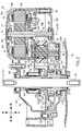
- FIG. 4 is a right side view showing a state where a driven gear is removed from the drive unit shown in FIG. 3. It is a longitudinal cross-sectional view which shows schematic structure of the drive unit which concerns on an application example.
- FIG. 1 is a right side view showing a schematic configuration of the battery-assisted bicycle 10.
- the battery-assisted bicycle 10 includes a body frame 12, a front wheel 14F, a rear wheel 14R, a handle 16, a saddle 18, and a drive unit 50.
- the body frame 12 includes a head pipe 12A, a main frame 12B, a down frame 12C, a seat frame 12D, a pair of chain stays 12E and 12E, a pair of seat stays 12F and 12F, and a bracket 12G.
- the head pipe 12A is disposed at the front portion of the battery-assisted bicycle 10 and extends in the vertical direction.
- a stem 20 is rotatably inserted into the head pipe 12A.
- a handle 16 is fixed to the upper end of the stem 20.
- a front fork 22 is fixed to the lower end of the stem 20.
- a front wheel 14F is rotatably attached to the lower end of the front fork 22.
- the main frame 12B is disposed behind the head pipe 12A and extends in the front-rear direction.
- the front end of the main frame 12B is connected to the upper end of the head pipe 12A.
- the rear end of the main frame 12B is connected to the upper end of a seat frame 12D that extends in the vertical direction.
- the down frame 12C is disposed behind the head pipe 12A and extends in the front-rear direction.
- the down frame 12C is disposed below the main frame 12B.
- the front end of the down frame 12C is connected to the head pipe 12A.
- the rear end of the down frame 12C is connected to the lower end of the seat frame 12D.
- the seat pipe 24 is inserted into the seat frame 12D.
- a saddle 18 is attached to the upper end of the seat pipe 24.
- the pair of chain stays 12E and 12E extend in the front-rear direction.
- a rear wheel 14R is disposed between the pair of chain stays 12E and 12E.
- the front end of each chain stay 12E is connected to the lower end of the seat frame 12D.
- a rear wheel 14R is rotatably attached at the rear end of each chain stay 12E.
- a driven sprocket 26 is disposed on the right side of the rear wheel 14R.
- the driven sprocket 26 is connected to the rear wheel 14R via a one-way clutch (not shown).
- the pair of seat stays 12F and 12F extend in the front-rear direction.
- the front end of each seat stay 12F is connected to the upper end of the seat frame 12D.
- the rear end of the seat stay 12F disposed on the right side of the rear wheel 14R is connected to the rear end of the chain stay 12E disposed on the right side of the rear wheel 14R.
- the rear end of the seat stay 12F disposed on the left side of the rear wheel 14R is connected to the rear end of the chain stay 12E disposed on the left side of the rear wheel 14R.
- a carrier 28 is disposed behind the saddle 18.
- the carrier 28 is attached to the pair of seat stays 12F and 12F.
- a battery unit 30 is disposed on the carrier 28.
- the battery unit 30 supplies power to the motor 60 (see FIG. 2) of the drive unit 50.
- the battery unit 30 includes a battery and a control unit.
- the battery is a chargeable / dischargeable rechargeable battery.
- the control unit controls the charging / discharging of the battery, and monitors the output current and the remaining amount of the battery.
- the bracket 12G covers the rear end of the down frame 12C, the lower end of the seat frame 12D, and the front end of each chain stay 12E.
- the drive unit 50 is fixed to the bracket 12G by a plurality of fasteners (not shown). Details of the drive unit 50 will be described later.
- An endless chain 32 is wound around the drive sprocket 58 and the driven sprocket 26 provided in the drive unit 50.
- crank arm 34R is attached to one axial end of the crankshaft 54 included in the drive unit 50, and one end of the crank arm 34L is attached to the other axial end.
- a pedal 36R is attached to the other end of the crank arm 34R, and a pedal 36L is attached to the other end of the crank arm 34L.
- FIG. 2 is a longitudinal sectional view showing a schematic configuration of the drive unit 50.
- the drive unit 50 includes a housing 52, a crankshaft 54, a rotating member 56, a drive sprocket 58, a motor 60, and a speed reduction mechanism 62.
- the housing 52 includes a first housing part 52L and a second housing part 52R.
- the first housing part 52L and the second housing part 52R are each made of a metal material.
- the metal material is, for example, an aluminum alloy.
- the first housing portion 52L and the second housing portion 52R are assembled from the left and right directions and are fixed to each other by a plurality of fastening fittings 66.
- the housing 52 is attached to the bracket 12G by a plurality of fasteners (not shown).
- the housing 52 will be described in a little more detail.
- the first housing portion 52A has an overlapping surface 53A.
- the second housing part 52B has an overlapping surface 53B.
- the overlapping surface 53A and the overlapping surface 53B are surfaces perpendicular to the axial direction of the crankshaft 54, respectively.
- the overlapping surface 53A and the overlapping surface 53B are overlapped. That is, the first housing portion 52A and the second housing portion 52B are overlapped in the axial direction of the crankshaft 54.
- crankshaft 54 is disposed so as to penetrate the housing 52 in the left-right direction. That is, the center axis L1 of the crankshaft 54 extends in the left-right direction. The center axis L1 coincides with the rotation center C1 of the crankshaft 54 when viewed from the axial direction of the crankshaft 54.
- the crankshaft 54 is supported by two bearings 68L and 68R so as to be rotatable around the central axis L1 of the crankshaft 54.
- the bearing 68L is disposed on one end side (left end side) in the axial direction of the crankshaft 54 with respect to the rotating member 56, and is fixed to the first housing portion 52L.
- the bearing 68R is disposed on the other axial end side (right end side) of the crankshaft 54 with respect to the bearing 68L, and is fixed to the second housing portion 52R.
- the crankshaft 54 is disposed through the rotating member 56.
- the drive sprocket 58 is disposed outside the housing 52 and on the right side of the housing 52, and rotates together with the rotating member 56. Details of the rotating member 56 will be described later.
- the motor 60 is disposed in the housing 52.
- the motor 60 generates a driving force for assisting the traveling of the battery-assisted bicycle 10 based on a control signal output from a control device (not shown).
- the motor 60 includes a stator 70, a rotor 72, an output shaft 74, and an output gear 76.
- the stator 70 includes a plurality of bobbins 70B (14 in this embodiment) around which coils 70A are wound. An iron core 70C is inserted into each bobbin 70B. The stator 70 is fixed to the first housing portion 52L. A cover 77 that covers the motor 60 from the left side is attached to the first housing portion 52L.
- the rotor 72 is disposed inside the stator 70.
- the rotor 72 is a permanent magnet in which N poles and S poles are alternately magnetized in the circumferential direction. In the present embodiment, the number of N poles and S poles is 7 respectively.
- the output shaft 74 is disposed through the rotor 72 and is fixed to the rotor 72. That is, the output shaft 74 rotates with the rotor 72.
- the output shaft 74 is made of a metal material.
- the metal material is, for example, iron.
- the center axis L2 of the output shaft 74 is parallel to the center axis L1 of the crankshaft 54. That is, the output shaft 74 extends in parallel to the central axis L1 of the crankshaft 54. Note that the center axis L2 coincides with the rotation center C2 of the output shaft 74 when viewed from the axial direction of the output shaft 74, that is, the axial direction of the crankshaft 54.
- the output shaft 74 is supported by the two bearings 78L and 78R so as to be rotatable around the central axis L2.
- the output shaft 74 is supported by the pair of bearings 78L and 78R so as to be rotatable around the central axis L2.
- the bearing 78 ⁇ / b> L is disposed on one axial end side (left end side) of the rotor 72 and is fixed to the cover 77.
- the bearing 78R is disposed on the other axial end side (right end side) of the rotor 72 and is fixed to the second housing portion 52R.
- the bearing 78L is disposed at a position different from the bearing 68L in the axial direction of the crankshaft 54.
- “the bearing 78L and the bearing 68L are arranged at different positions in the axial direction of the crankshaft 54” means that the bearing 78L is viewed from a direction orthogonal to the central axis L1 of the crankshaft 54. This means that it does not overlap the bearing 68L.
- the bearing 78L is arranged farther from the bearing 68R than the bearing 68L in the axial direction of the crankshaft 54.
- the bearing 78R is disposed at a position different from the bearing 68R in the axial direction of the crankshaft 54.
- “the bearing 78R and the bearing 68R are arranged at different positions in the axial direction of the crankshaft 54” means that the bearing 78R is viewed from a direction orthogonal to the central axis L1 of the crankshaft 54. This means that it does not overlap the bearing 68R.
- the bearing 78R is disposed between the bearing 68L and the bearing 68R in the axial direction of the crankshaft 54.
- the bearing 78R is disposed closer to the bearing 68R than the bearing 68L in the axial direction of the crankshaft 54.
- FIG. 3 is a right side view showing the drive unit 50 with the second housing portion 52R removed.
- the rotation center C2 is located in front of the rotation center C1 of the crankshaft 54.
- the rotation center C2 is located above the rotation center C1 (see FIG. 3).
- FIG. 4 is a longitudinal sectional view showing the positional relationship between the output shaft 74, the rotor 72, and the bearings 78L and 78R.
- the output gear 76 is formed on the output shaft 74 on the other axial end side (right end side) of the rotor 72. That is, the output gear 76 is made of a metal material and is disposed on the output shaft 74.
- the output gear 76 is formed closer to the bearing 78R than the center C0 of the axial length of the output shaft 74.
- the center C0 is located closer to the bearing 78R than the rotor 72 is.
- the bearing 78 ⁇ / b> R is arranged farther from the rotor 72 than the output gear 76 in the axial direction of the output shaft 74. That is, the bearing 78 ⁇ / b> R is disposed on the opposite side of the rotor 72 with respect to the output gear 76 in the axial direction of the output shaft 74.
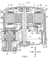
- FIG. 5 is an enlarged longitudinal sectional view showing a part of FIG.
- the electrical component 80 is disposed around the output shaft 74.
- the electric component 80 is used to drive and control the motor 60. At least a part of the electrical component 80 overlaps the motor 60 when viewed from the axial direction of the crankshaft 54.
- the electrical component 80 includes a detected portion 80A, a plurality of bus bars 80B, a substrate 80C, a detection element 80D, and a connector 80E.
- the detected portion 80 ⁇ / b> A is disposed between the rotor 72 and the output gear 76 in the axial direction of the output shaft 74.
- the detected portion 80A has a ring shape.
- An output shaft 74 is inserted into the detected part 80A.
- the detected portion 80A is arranged coaxially with the output shaft 74.
- the detected portion 80A is fixed to the output shaft 74. That is, the detected portion 80A rotates with the output shaft 74.
- 80 A of to-be-detected parts are arrange
- Each of the plurality of bus bars 80B is embedded in a support portion 80F made of an insulating material (for example, synthetic resin).
- the substrate 80C is supported by the support portion 80F.
- the support portion 80F is attached to the bobbin 70B.
- the detection element 80 ⁇ / b> D provided on the substrate 80 ⁇ / b> C is disposed to face the detected portion 80 ⁇ / b> A in the axial direction of the output shaft 74.
- the detection element 80D detects the rotation of the detected part 80A by detecting a change in magnetism that occurs with the rotation of the detected part 80A.
- a control device controls the rotation of the rotor 72.
- a connector (not shown) for connecting the board 80C and the control device is connected to the connector 80E provided on the board 80C.
- the speed reduction mechanism 62 will be described with reference to FIGS. 2 and 5.
- the speed reduction mechanism 62 includes a transmission shaft 82, a first transmission gear 84, and a second transmission gear 86.
- the transmission shaft 82 is disposed in the housing 52.
- the central axis L3 of the transmission shaft 82 is parallel to the central axis L1 of the crankshaft 54. That is, the transmission shaft 82 extends in parallel to the central axis L1 of the crankshaft 54.
- the center axis L3 coincides with the rotation center C3 of the transmission shaft 82 when viewed from the axial direction of the transmission shaft 82, that is, the axial direction of the crankshaft 54.
- the transmission shaft 82 is supported by two bearings 88L and 88R so as to be rotatable around the central axis L3.
- the bearing 88L is fixed to the first housing portion 52L.
- the bearing 88R is fixed to the second housing portion 52R.
- At least a part of the bearing 88L overlaps the stator 70 when viewed from the axial direction of the crankshaft 54.
- the rotation center C3 of the transmission shaft 82 overlaps the stator 70 when viewed from the axial direction of the crankshaft 54. That is, the rotation center C3 of the transmission shaft 82 overlaps the motor 60 when viewed from the axial direction of the crankshaft 54 (see FIG. 3).
- the bearing 88L is disposed at the same position as the electric component 80 in the axial direction of the crankshaft 54.
- “the bearing 88L and the electric component 80 are disposed at the same position in the axial direction of the crankshaft 54” means that the bearing 88L is viewed from a direction orthogonal to the central axis L1 of the crankshaft 54. That at least a part of is overlapped with the electric component 80.
- the electrical component 80 is not disposed between the bearing 88L and the motor 60 in the axial direction of the crankshaft 54. That is, the bearing 88L and the electric component 80 are arranged at different positions in the circumferential direction around the central axis L2 of the output shaft 74. In other words, when viewed from the axial direction of the crankshaft 54, at least a part of the bearing 88 ⁇ / b> L and at least a part of the electrical component 80 overlap the motor 60 in different regions.
- the bearing 88L is disposed at a position different from the bearing 78L in the axial direction of the crankshaft 54.
- “the bearing 88L and the bearing 78L are arranged at different positions in the axial direction of the crankshaft 54” means that the bearing 88L is viewed from a direction orthogonal to the central axis L1 of the crankshaft 54. This means that it does not overlap the bearing 78L.
- the bearing 88L is disposed closer to the bearing 78R than the bearing 78L in the axial direction of the crankshaft 54.
- the bearing 88R is disposed at a position different from the bearing 78R in the axial direction of the crankshaft 54.
- “the bearing 88R and the bearing 78R are disposed at different positions in the axial direction of the crankshaft 54” means that the bearing 88R is viewed from a direction orthogonal to the central axis L1 of the crankshaft 54. This means that it does not overlap the bearing 78R.
- the bearing 88R is arranged farther from the bearing 78L than the bearing 78R in the axial direction of the crankshaft 54.
- the bearing 88L is arranged at a position different from the bearing 68L in the axial direction of the crankshaft 54, as shown in FIG.
- “the bearing 88L and the bearing 68L are arranged at different positions in the axial direction of the crankshaft 54” means that the bearing 88L is viewed from a direction orthogonal to the central axis L1 of the crankshaft 54. This means that it does not overlap the bearing 68L.
- the bearing 88L is disposed between the bearing 68L and the bearing 68R in the axial direction of the crankshaft 54.
- the bearing 88L is disposed closer to the bearing 68L than the bearing 68R in the axial direction of the crankshaft 54.
- the bearing 88R is arranged at the same position as the bearing 68R in the axial direction of the crankshaft 54 as shown in FIG.
- “the bearing 88R and the bearing 68R are disposed at the same position in the axial direction of the crankshaft 54” means that the bearing 88R is viewed from a direction orthogonal to the central axis L1 of the crankshaft 54. It means that at least a part overlaps the bearing 68R.
- the rotation center C3 of the transmission shaft 82 is located in front of the rotation center C1 of the crankshaft 54 and is located in the rear of the rotation center C2 of the output shaft 74. As shown in FIG. 3, the rotation center C3 is positioned above the rotation center C1 and above the rotation center C2.
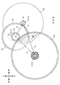
- the first line segment S1 connecting the rotation center C1 and the rotation center C2, the second line segment S2 connecting the rotation center C2 and the rotation center C3, the rotation center C3, and the rotation center C1.
- a triangle is formed by the third line segment S3 connecting the two.
- the first line segment S1 is longer than the second line segment S2 and the third line segment S3.
- the first transmission gear 84 is made of synthetic resin.
- the first transmission gear 84 is disposed on the transmission shaft 82.
- the first transmission gear 84 is disposed closer to the bearing 88R than the bearing 88L in the axial direction of the transmission shaft 82.
- the first transmission gear 84 meshes with the output gear 76.
- a one-way clutch 83 is disposed between the first transmission gear 84 and the transmission shaft 82.
- the first transmission gear 84 rotates in the reverse direction, and the output gear 76 rotates in the reverse direction (wrong direction). In this case, the first transmission gear 84 does not rotate.
- the first transmission gear 84 has a larger diameter than the output gear 76 and has more teeth than the output gear 76. That is, the first transmission gear 84 is decelerated more than the output gear 76.
- the second transmission gear 86 is made of a metal material.
- the metal material is, for example, iron.
- the second transmission gear 86 is disposed on the transmission shaft 82.
- the second transmission gear 86 is disposed at a position different from the first transmission gear 84 in the axial direction of the transmission shaft 82.
- the second transmission gear 86 is fixed to the transmission shaft 82 by spline fitting. That is, the second transmission gear 86 rotates together with the transmission shaft 82.
- the second transmission gear 86 is supported by the bearing 88R so as to be rotatable around the central axis L3 of the transmission shaft 82. That is, the second transmission gear 86 is further away from the bearing 88L than the first transmission gear 84.
- the second transmission gear 86 is disposed at the same position as the bearing 78R in the axial direction of the crankshaft 54.
- “the second transmission gear 86 and the bearing 78R are disposed at the same position in the axial direction of the crankshaft 54” means that when viewed from a direction orthogonal to the central axis L1 of the crankshaft 54, It means that at least a part of the second transmission gear 86 overlaps the bearing 78R.
- the second transmission gear 86 does not overlap the first line segment S1.
- FIG. 7 is an enlarged longitudinal sectional view showing a part of FIG.
- the rotating member 56 is disposed coaxially with the crankshaft 54 and rotates together with the crankshaft 54.
- the rotating member 56 includes a connecting shaft portion 56A, a torque detection device 56B, and a one-way clutch 56C.
- the connecting shaft portion 56A is disposed at one end portion (left end portion) in the axial direction of the rotating member 56, and is located in the housing 52 (see FIG. 2).
- the connecting shaft portion 56A has a cylindrical shape.
- the crankshaft 54 is inserted into the connecting shaft portion 56A.
- the connecting shaft portion 56A is disposed coaxially with the crankshaft 54.
- Serrations 92 are formed on the inner peripheral surface of the axial end portion of the connecting shaft portion 56A.
- the serrations 92 mesh with serrations 54 ⁇ / b> A formed on the outer peripheral surface of the crankshaft 54.
- the connecting shaft portion 56A is connected to the crankshaft 54.
- the connecting shaft portion 56 ⁇ / b> A rotates together with the crankshaft 54 regardless of whether the crankshaft 54 rotates in the forward rotation direction or the reverse rotation direction.
- a slide bearing 106 is disposed between the other axial end portion of the connecting shaft portion 56A and the crankshaft 54.
- the torque detection device 56B is disposed in the housing 52 (see FIG. 2).
- the torque detection device 56B detects the torque generated in the crankshaft 54 when the driver pedals the pedals 36R and 36L (see FIG. 1).
- the torque detection device 56B is a magnetostrictive torque sensor.
- the torque detection device 56B includes a mounting shaft portion 94, a coil 96, a detection element 98, and a shield 100.
- the attachment shaft portion 94 is attached to the outer peripheral surface of the connection shaft portion 56A and rotates relative to the connection shaft portion 56A. That is, the attachment shaft portion 94 does not rotate with the connecting shaft portion 56A.
- the coil 96 is disposed on the outer peripheral surface of the mounting shaft portion 94.
- the detection element 98 detects torque generated in the crankshaft 54 by detecting a voltage change of the coil 96 due to the distortion of the connecting shaft portion 56A.
- the detection element 98 outputs the detected torque to a control device (not shown).
- the control device refers to the torque output from the detection element 98, grasps the pedaling state by the driver, and controls the motor 60.
- the shield 100 prevents the detection accuracy of the detection element 98 from deteriorating due to an external magnetic field.
- the shield 100 engages with an engagement piece (not shown) formed in the first housing portion 52L. That is, the shield 100 does not rotate with the connecting shaft portion 56A.
- the one-way clutch 56C is disposed coaxially with the crankshaft 54 on the drive sprocket 58 side of the torque detection device 56B.
- the one-way clutch 56 ⁇ / b> C transmits the rotational force that rotates the crankshaft 54 in the forward rotation direction to the drive sprocket 58, and does not transmit the rotational force that rotates the crankshaft 54 in the backward rotation direction to the drive sprocket 58.
- the one-way clutch 56 ⁇ / b> C includes a driving member 102 and a driven gear 104.
- the drive member 102 includes a main body portion 108 and a cylinder portion 110.
- the main body 108 has a ring shape.
- the crankshaft 54 is inserted into the main body 108.
- the main body 108 is disposed coaxially with the crankshaft 54.
- Serrations 112 are formed on the inner peripheral surface of the main body 108.
- the serration 112 meshes with a serration 114 formed on the outer peripheral surface of the other axial end portion of the connecting shaft portion 56A.
- the main body portion 108, that is, the drive member 102 is connected to the connecting shaft portion 56A.
- the main body portion 108, that is, the drive member 102 rotates together with the connecting shaft portion 56A.
- the drive member 102 rotates with the crankshaft 54 regardless of whether the crankshaft 54 rotates in the forward rotation direction or the reverse rotation direction.
- the cylinder part 110 is disposed coaxially with the main body part 108 on the drive sprocket 58 side of the main body part 108.
- the cylinder part 110 is a cylindrical member and is disposed coaxially with the crankshaft 54.
- the cylinder part 110 is formed integrally with the main body part 108.
- the driven gear 104 includes a shaft portion 116.
- the shaft portion 116 has a cylindrical shape.
- a crankshaft 54 is inserted into the shaft portion 116.
- the shaft portion 116 is disposed coaxially with the crankshaft 54 and is disposed coaxially with the drive member 102. That is, the driven gear 104 is disposed coaxially with the crankshaft 54 and is disposed coaxially with the driving member 102.
- Slide bearings 122 and 124 are disposed between the shaft portion 116 and the crankshaft 54. As a result, the driven gear 104 can rotate relative to the crankshaft 54.
- the shaft portion 116 includes a driven shaft portion 117 and a mounting shaft portion 118.
- the driven shaft portion 117 is disposed closer to the drive member 102 than the mounting shaft portion 118 and is coaxial with the mounting shaft portion 118.
- the driven shaft portion 117 is formed integrally with the mounting shaft portion 118.
- the driven shaft portion 117 is disposed inside the cylindrical portion 110 in a direction orthogonal to the central axis L1 of the crankshaft 54.
- a ratchet mechanism 120 is disposed between the driven shaft portion 117 and the cylindrical portion 110.
- the mounting shaft portion 118 is supported by the second bearing 68R so as to be rotatable around the central axis of the crankshaft 54.
- the attachment shaft portion 118 has a portion located on the opposite side of the drive member 102 with respect to the second bearing 68R.
- a drive sprocket 58 is attached to this portion (see FIG. 2).
- the one-way clutch 56C allows the rotational force that rotates the drive sprocket 58 in the forward rotation direction around the center axis L1 of the crankshaft 54 to be transmitted to the drive sprocket 58, but causes the drive sprocket 58 to move in the reverse rotation direction.
- the rotational force to be rotated is prevented from being transmitted to the drive sprocket 58.
- the driven gear 104 meshes with the second transmission gear 86.
- the driven gear 104 is larger in diameter than the second transmission gear 86 and has more teeth than the second transmission gear 86. That is, the driven gear 104 is decelerated more than the second transmission gear 86.
- the driven gear 104 is disposed at the same position as the bearing 78R in the axial direction of the crankshaft 54.
- “the driven gear 104 and the bearing 78R are disposed at the same position in the axial direction of the crankshaft 54” means that the driven gear 104 and the bearing 78R are viewed from a direction perpendicular to the central axis L1 of the crankshaft 54. It means that at least a part of the drive gear 104 overlaps the bearing 78R.
- the driven gear 104 is made of a metal material.
- the metal material is, for example, iron.
- the driven gear 104 has a larger diameter than the motor 60 and a larger diameter than the first transmission gear 84 when viewed from the axial direction of the crankshaft 54.
- the motor 60 has a larger diameter than the first transmission gear 84. That is, among the motor 60, the first transmission gear 84, and the driven gear 104, the member (first member) having the largest diameter when viewed from the axial direction of the crankshaft 54 is the driven gear 104. The member with the next largest diameter (second member) is the motor 60. The member with the smallest diameter (third member) is the first transmission gear.
- At least a part of the driven gear 104 overlaps the motor 60 when viewed from the axial direction of the crankshaft 54. At least a portion of the first transmission gear 84 overlaps a region 126 where the driven gear 104 and the motor 60 overlap when viewed from the axial direction of the crankshaft 54. That is, at least a part of the first transmission gear 84 overlaps each of the driven gear 104 and the motor 60 when viewed from the axial direction of the crankshaft 54.
- the rotation detection device 130 will be described with reference to FIG.
- the rotation detection device 130 is disposed in the housing 52 and detects the rotation of the crankshaft 54.
- the rotation detection device 130 includes a ring magnet 132 as a detected portion and a detection element 134 that detects the rotation of the ring magnet 132.
- the ring magnet 132 has an annular plate shape.
- the end surface in the axial direction becomes a magnetic pole forming surface. That is, in the ring magnet 132, N poles and S poles are alternately formed around the central axis L1 of the crankshaft 54 at the end face in the axial direction.
- the ring magnet 132 is attached to the support member 136.
- the support member 136 includes a cylindrical portion 138 and an annular portion 140.
- the cylinder portion 138 extends in the axial direction of the crankshaft 54.
- the cylinder part 138 is fixed to the outer peripheral surface of the cylinder part 110.
- Examples of a method for fixing the tube portion 138 to the outer peripheral surface of the tube portion 110 include press-fitting and adhesion.
- the annular portion 140 is disposed coaxially with the cylindrical portion 138 at one axial end of the cylindrical portion 138.
- the annular portion 140 is formed integrally with the cylindrical portion 138.
- the annular portion 140 includes a mounting surface 136A.
- the mounting surface 136A is an end surface in the axial direction of the annular portion 140, and is an annular surface that extends in a direction perpendicular to the central axis L1 of the crankshaft 54.
- the ring magnet 132 is superposed on the annular portion 140 in the axial direction of the crankshaft 54. In this state, the end surface of the ring magnet 132 in the axial direction and the mounting surface 136A are bonded.
- the cylindrical portion 138 is fixed to the outer peripheral surface of the cylindrical portion 110. That is, the ring magnet 132 rotates together with the rotating member 56.
- the detection element 134 is disposed in the axial direction of the crankshaft 54 so as to face the magnetic pole forming surface of the ring magnet 132.
- the detection element 134 detects that the ring magnet 132 rotates together with the rotating member 56.
- the detection element 134 detects a change in the magnetic field generated as the ring magnet 132 rotates together with the rotating member 56. That is, in the present embodiment, the rotation detection device 130 is a magnetic rotation detection sensor.
- the ring magnet 132 is provided in the driving member 102 that rotates together with the crankshaft 54 in the rotating member 56. Therefore, the rotation of the crankshaft 54 is detected by detecting the change in the magnetic field generated with the rotation of the ring magnet 132.
- the detection element 134 outputs the detected rotation of the crankshaft 54 to a control device (not shown).
- the control device refers to not only the torque detected by the detection element 98 but also the rotation of the crankshaft 54 detected by the detection element 134, grasps the pedaling state by the driver, and controls the motor 60.
- the detection element 134 is a one-chip Hall IC and includes two detection elements. Thereby, the transverse magnetic field and the longitudinal magnetic field of the ring magnet 132 can be detected. As a result, it can be determined whether the ring magnet 132 is rotating in the forward rotation direction or the reverse rotation direction.
- the detection element 134 is provided on the substrate 150.
- the board 150 is a printed wiring board.
- the substrate 150 is disposed in the housing 52 as shown in FIG.
- a control device (not shown) that controls the operation of the drive unit 50 is mounted on the substrate 150.
- the substrate 150 is coated with a waterproof coating material.
- FIG. 8 is a right side view for explaining the substrate 150.
- the hatched portion is the substrate 150.
- FIG. 9 is a right side view for explaining the first region 154.
- the hatched portion is the first region 154.
- FIG. 10 is a longitudinal sectional view for explaining the relationship between the first region 154 and the second housing portion 52R.
- FIG. 11 is a right side view for explaining the second region 162 and the third region 164. In FIG. 11, the hatched portions are the second region 162 and the third region 164.
- the substrate 150 has a mounting surface 152.
- the mounting surface 152 is one end surface in the thickness direction of the substrate 150.
- Various electrical components for controlling the operation of the drive unit 50 are mounted on the mounting surface 152.
- the mounting surface 152 extends in a direction orthogonal to the central axis L1 of the crankshaft 54.
- the substrate 150 is disposed between the driven gear 104 and the motor 60 in the axial direction of the crankshaft 54.
- the substrate 150 is disposed between the driven gear 104 and the motor 60 means that the stator 70 having the largest diameter when viewed from the axial direction of the crankshaft 54 of the motor 60, and the driven It means that the substrate 150 is disposed between the gear 104.
- the substrate 150 is disposed along the overlapping surfaces 53L and 53R of the first housing portion 52L and the second housing portion 52R.
- “the substrate 150 is arranged along the overlapping surfaces 53L and 53R” means that the end surface in the thickness direction of the substrate 150 coincides with the overlapping surfaces 53L and 53R in the axial direction of the crankshaft 54.
- the end surface in the thickness direction of the substrate 150 may not exactly coincide with the overlapping surfaces 53L and 53R in the axial direction of the crankshaft 54.
- the overlapping surfaces 53L and 53R may be at the same position as the substrate 150 in the axial direction of the crankshaft 54.
- “the overlapping surfaces 53L and 53R are in the same position as the substrate 150 in the axial direction of the crankshaft 54” means that the overlapping surfaces are viewed from a direction orthogonal to the central axis L1 of the crankshaft. This means that 53L and 53R overlap the substrate 150.
- the substrate 150 is disposed at the same position as the first transmission gear 84 in the axial direction of the crankshaft 54.
- “the substrate 150 and the first transmission gear 84 are disposed at the same position in the axial direction of the crankshaft 54” means that when viewed from a direction orthogonal to the central axis L1 of the crankshaft 54, This means that the substrate 150 overlaps the first transmission gear 84.
- the substrate 150 when viewed from the axial direction of the crankshaft 54, the substrate 150 is disposed on the opposite side of the rotation center C3 with respect to the first line segment S1.
- the substrate 150 when viewed from the axial direction of the crankshaft 54, the substrate 150 does not overlap the rotation center C1 and the rotation center C2.
- the substrate 150 has a first region 154 that overlaps the motor 60 when viewed from the axial direction of the crankshaft 54.
- an electrical component 156 is arranged in the first region 154.
- the electrical component 156 is a switching element that supplies power to the motor 60.
- the electrical component 156 is disposed on the mounting surface 152.
- a heat transfer sheet 158 is disposed in a region of the first region 154 where the electrical component 156 is disposed.
- the heat transfer sheet 158 is disposed on the back surface of the substrate 150 (the surface opposite to the mounting surface 152 in the thickness direction of the substrate 152).
- the heat transfer sheet 158 has a higher thermal conductivity than the coating material that coats the substrate 150. The heat transfer sheet 158 releases heat generated by the electric component 156.
- the heat transfer sheet 158 contacts the inner surface of the second housing portion 52R.
- the first region 154 contacts the inner surface of the second housing portion 52R via the heat transfer sheet 158.
- the second housing portion 52 ⁇ / b> R has a plurality of heat radiation fins 160 in a region overlapping the heat transfer sheet 158.
- the plurality of heat dissipating fins 160 are formed in a region overlapping the heat transfer sheet 158 when viewed from the axial direction of the crankshaft 54 on the outer surface of the second housing portion 52R.
- the substrate 150 has a second region 162 that overlaps the driven gear 104 when viewed from the axial direction of the crankshaft 54.
- the second region 162 includes a third region 164 that overlaps the ring magnet 132 when viewed from the axial direction of the crankshaft 54.
- the detection element 134 is disposed at a position overlapping the third region 164.
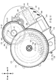
- Partition wall The partition wall 170 will be described with reference to FIGS. 2, 3, 8, 12, 13, and 14. 12 and 13 are perspective views showing the partition wall 170. FIG. In FIG. 14, the driven gear 104 is removed compared to FIG. 3.
- the partition wall 170 is arrange
- the first wall portion 172 extends in a direction orthogonal to the central axis L1 of the crankshaft 54, as shown in FIG. As shown in FIGS. 8 and 12 to 14, a through hole 180 is formed in the first wall portion 172. As shown in FIG. 14, the drive member 102 is disposed in the through hole 180. As apparent from FIGS. 2, 3, 8, and 14, the first wall portion 172 is disposed between the substrate 150 and the driven gear 104 in the axial direction of the crankshaft 54.
- “the first wall portion 172 is disposed between the substrate 150 and the driven gear 104” means that the first wall portion 172 has teeth (second transmission) that the substrate 150 and the driven gear 104 have. It is arranged between the gear 86 and the portion engaged with the gear 86. That is, the space formed between the substrate 150 and the teeth of the driven gear 104 (the portion that meshes with the second transmission gear 86) is partitioned by the first wall portion 172.
- 2nd wall part 174 spreads in the direction orthogonal to the central axis L1 of the crankshaft 54, as shown in FIG.3 and FIG.8.
- the second wall portion 174 is disposed at a position different from the first wall portion 172 in the axial direction of the crankshaft 54.
- “the second wall portion 174 is disposed at a position different from the first wall portion 172 in the axial direction of the crankshaft 54” means that the second wall portion 174 is viewed from a direction orthogonal to the central axis L1 of the crankshaft.
- the second wall portion 174 does not overlap the first wall portion 172.
- two through holes 182 and 184 are formed in the second wall portion 174.
- the through hole 182 is larger than the through hole 184.
- the rotation center C ⁇ b> 2 is located in the through hole 182.
- the bearing 88 ⁇ / b> L is located in the through hole 182 when viewed from the axial direction of the crankshaft 54.
- the output shaft 74 is positioned in the through hole 184 when viewed from the axial direction of the crankshaft 54. That is, the output shaft 74 is inserted through the through hole 184.
- the third wall portion 176 is formed along the outer edge of the second wall portion 174.
- the third wall portion 176 extends from the one end surface in the thickness direction of the second wall portion 174 in one thickness direction.
- the third wall portion 176 includes a first peripheral wall portion 186 and a second peripheral wall portion 188.
- the first peripheral wall portion 186 is formed around the through hole 182.
- the second peripheral wall portion 188 is formed around the through hole 184.
- One end in the circumferential direction of the first peripheral wall portion 186 and the other end in the circumferential direction of the second peripheral wall portion 188 are connected.
- the other circumferential end of the first peripheral wall 186 and one circumferential end of the second peripheral wall 188 are connected.
- the first transmission gear 84, the second transmission gear 86, and the output gear 76 are disposed inside the third wall portion 176.
- the first transmission gear 84 is disposed inside the first peripheral wall 186.
- the first transmission gear 84 is disposed at the same position as the third wall portion 176 in the axial direction of the crankshaft 54 as shown in FIG.
- “the first transmission gear 84 is disposed at the same position as the third wall portion 176 in the axial direction of the crankshaft 54” means when viewed from a direction orthogonal to the central axis L 1 of the crankshaft 54.
- it means that at least a part of the first transmission gear 84 overlaps the third wall portion 176.
- the output gear 76 is disposed inside the second peripheral wall portion 188.
- the output gear 76 is disposed at the same position as the third wall portion 176 in the axial direction of the crankshaft 54 as shown in FIG.
- “the output gear 76 is disposed at the same position as the third wall portion 176 in the axial direction of the crankshaft 54” means that when viewed from a direction orthogonal to the central axis L1 of the crankshaft 54, It means that at least a part of the output gear 76 overlaps the third wall portion 176.
- the second transmission gear 86 is disposed at a position different from the third wall portion 176 in the axial direction of the crankshaft 54 as shown in FIG.
- “the second transmission gear 86 is disposed at a position different from the third wall portion 176 in the axial direction of the crankshaft 54” means that the second transmission gear 86 is viewed from a direction orthogonal to the central axis L 1 of the crankshaft 54.
- the second transmission gear 86 does not overlap the third wall 176.
- the substrate 150 is disposed outside the second peripheral wall portion 188 in a direction orthogonal to the central axis L ⁇ b> 2 of the output shaft 74. That is, the space formed between the substrate 150 and the output gear 76 is partitioned by the second peripheral wall portion 188.
- the fourth wall portion 178 extends in a direction orthogonal to the central axis L ⁇ b> 1 of the crankshaft 54.
- the fourth wall portion 178 is connected to the first wall portion 172.
- the fourth wall portion 178 overlaps the substrate 150 when viewed from the axial direction of the crankshaft 54.
- the crankshaft 54 rotates in the forward direction when the driver strokes the pedals 36 ⁇ / b> L and 36 ⁇ / b> R.
- the connecting shaft portion 56A rotates in the forward rotation direction.
- the drive member 102 rotates in the forward rotation direction.
- the driven gear 104 rotates in the forward rotation direction.
- the drive member 102 rotates in the backward rotation direction, that is, when the crankshaft 54 rotates in the backward rotation direction
- the drive member 102 rotates relative to the driven gear 104.
- the driven gear 104 rotates in the forward rotation direction
- the drive sprocket 58 rotates in the forward rotation direction. The rotational force of the drive sprocket 58 is transmitted to the driven sprocket 26 via the chain 32.
- Torque is generated in the crankshaft 54 when the driver strokes the pedals 36L and 36R. Torque generated in the crankshaft 54 is detected by the torque detector 56B.
- the rotor 72 of the motor 60 that is, the output shaft 74 rotates in the forward rotation direction.
- the output gear 76 rotates in the forward rotation direction.
- the first transmission gear 84 rotates in the backward rotation direction.
- the second transmission gear 86 rotates in the backward rotation direction.
- the driven gear 104 rotates in the forward rotation direction.
- the attachment shaft portion 118 rotates in the forward rotation direction.
- the drive sprocket 58 rotates in the forward rotation direction. As a result, pedaling by the driver is assisted.
- the rotation detection device 130 detects the rotation of the crankshaft 54. Therefore, not only the torque generated in the crankshaft 54 but also the rotation of the crankshaft 54 can be referred to and the state of pedaling by the driver can be grasped. As a result, the state of pedaling by the driver can be accurately grasped, so that, for example, it becomes easier to detect a failure and more accurate assistance can be performed.
- the battery-assisted bicycle 10 includes a drive unit 50.
- the drive unit 50 includes a crankshaft 54, a motor 60 and a transmission shaft 82.
- the transmission shaft 82 extends in parallel to the central axis L1 of the crankshaft 54.
- the motor 60 includes a rotor 72, an output shaft 74, and an output gear 76.
- the output shaft 74 rotates together with the rotor 72 and extends parallel to the central axis L1 of the crankshaft 54.
- the output gear 76 is disposed on the output shaft 74.
- the drive unit 50 further includes a first transmission gear 84, a second transmission gear 86, a driven gear 104, and a plurality of bearings 78L and 78R.
- the first transmission gear 84 is disposed on the transmission shaft 82, meshes with the output gear 76, and has more teeth than the output gear 76.
- the second transmission gear 86 is disposed on the transmission shaft 82.
- the driven gear 104 is disposed on the crankshaft 54, meshes with the second transmission gear 86, and has more teeth than the second transmission gear 86.
- the plurality of bearings 78L and 78R support the output shaft 74 rotatably around the central axis L2 of the output shaft 74.
- the plurality of bearings 78L and 78R include a first bearing 78R disposed at the same position as the second transmission gear 86 in the axial direction of the crankshaft 54.
- the first bearing 78R is disposed at the same position as the driven gear 104 in the axial direction of the crankshaft 54.
- the first bearing 78 ⁇ / b> R is a bearing 78 ⁇ / b> R disposed on the opposite side of the rotor 72 from the output gear 76 in the axial direction of the output shaft 74.
- the first bearing 78R can be arranged away from the rotor 72. Therefore, the space between the first bearing 78R and the rotor 72 can be used effectively.
- an electrical component 80 used to drive and control the motor 60 can be disposed between the first bearing 78R and the rotor 72.
- the axial length of the first transmission gear 84 that meshes with the output gear 76 can be increased. Therefore, even if the first transmission gear 84 is formed of synthetic resin, the durability of the first transmission gear 84 can be ensured. In addition, since the first transmission gear 84 can be formed of synthetic resin, the sound generated when the first transmission gear 84 and the output gear 76 mesh can be reduced.
- the center of the axial length of the output shaft is located closer to the first bearing 78R than the rotor 72. In this case, it becomes easy to ensure the axial length of the output gear 76.
- the load applied to the bearing 78R can be reduced as compared with the case where the bearing 78R is disposed between the output gear 76 and the rotor 72. As a result, downsizing of the bearing 78R (downsizing of the output shaft 74 in the axial direction) can be realized.
- the drive unit 50 includes an electrical component 80 and a second bearing 88L.
- the electrical component 80 is disposed around the output shaft 74 and is used to drive and control the motor 60.
- the second bearing 88L supports the transmission shaft 82 so as to be rotatable around the central axis L3 of the transmission shaft 82.
- at least a part of the second bearing 88L and at least a part of the electrical component 80 overlap the motor 60 in different regions.
- the second bearing 88L is disposed at the same position as the electric component 80 in the axial direction of the crankshaft 54.
- a first line segment S1 connecting the rotation center C1 of the crankshaft 54 and the rotation center C2 of the output shaft 74, and a first line segment S1 connecting the rotation center C2 of the output shaft 74 and the rotation center C3 of the transmission shaft 82 are provided.
- a triangle is formed by the two line segments S2 and the third line segment S3 connecting the rotation center C3 of the transmission shaft 82 and the rotation center C1 of the crankshaft 54.
- the first bearing 78R can be brought closer to the driven gear 104 as compared with the case where the crankshaft 54, the output shaft 74, and the transmission shaft 82 are arranged in a straight line. As a result, a space (a useless space) formed between the first bearing 78R and the driven gear 104 can be filled.
- the driven gear 104 overlaps the motor 60 when viewed from the axial direction of the crankshaft 54.
- the first bearing 78R can be made closer to the drive gear.
- the space (waste space) formed between the first bearing 78R and the driven gear 104 can be further filled.
- the drive unit 50 further includes a one-way clutch 56C.
- the one-way clutch 56C is disposed on the crankshaft 54.
- the one-way clutch 56 ⁇ / b> C transmits a rotational force that rotates the crankshaft 54 in the first direction to a drive sprocket 58 disposed on the crankshaft 54.
- the one-way clutch 56 ⁇ / b> C does not transmit the rotational force that rotates the crankshaft 54 in the direction opposite to the first direction to the drive sprocket 58.
- the one-way clutch 56 ⁇ / b> C includes a driven gear 104.
- the driven gear 104 includes an attachment shaft portion 118 to which the drive sprocket 58 is attached.
- the bearing 78R is arranged at the same position as the second transmission gear 86 in the axial direction of the crankshaft 54.
- the second transmission gear 86 may be disposed at the same position. That is, the bearing disposed at the same position as the second transmission gear 86 in the axial direction of the crankshaft 54 is a bearing 78L disposed on the opposite side of the rotor 72 from the output gear 76 in the axial direction of the output shaft 74. There may be.
- a driving force transmission path from the output shaft 74 to the driven gear 104 can be formed on both sides of the stator 70 in the axial direction of the crankshaft 54. As a result, the space in the housing 52 can be used effectively.
Landscapes
- Engineering & Computer Science (AREA)
- Chemical & Material Sciences (AREA)
- Combustion & Propulsion (AREA)
- Transportation (AREA)
- Mechanical Engineering (AREA)
- Connection Of Motors, Electrical Generators, Mechanical Devices, And The Like (AREA)
Abstract
電動補助自転車に用いられる駆動ユニットにおいて、スペースを有効利用できるようにする。駆動ユニット(50)は、モータ(60)を備える。モータ(60)は、ロータ(72)、出力軸(74)及び出力歯車(76)を含む。出力軸(74)は、ロータ(72)とともに回転し、クランクシャフト(54)の中心軸線(L1)に対して平行に延びる。出力歯車(76)は、出力軸(74)に配置される。複数の軸受(78L,78R)は、出力軸(74)の中心軸線(L2)周りで出力軸(74)を回転可能に支持する。複数の軸受(78L,78R)は、クランクシャフト(54)の軸方向で第2伝達歯車(86)と同じ位置に配置される第1軸受(78R)を含む。
Description
本発明は、電動補助自転車に用いられる駆動ユニット及び当該駆動ユニットを備える電動補助自転車に関する。
近年、運転者がペダルを漕ぐ力(以下、踏力と称する)をモータの駆動力によってアシストする電動補助自転車が提案されている。電動補助自転車は、踏力をアシストするための駆動ユニットを備える。駆動ユニットは、例えば、特開2008-114851号公報に開示されている。
上記公報において、駆動ユニットは、回転部材を備える。回転部材は、ペダルクランク軸と同一軸線上で回転自在に設けられる。回転部材は、人力駆動系とモータ駆動系とを連結する。回転部材よりも車体の後方には、モータが配置される。モータと回転部材とは、歯車減速機を介して、連結される。
上記公報において、モータ出力軸は、複数の軸受により、モータ出力軸の中心軸線周りで回転可能に支持される。軸受を配置するためには、スペースを確保する必要がある。そのため、軸受を配置する場所によっては、軸受の近くに他の部材を配置するためのスペースを確保することが難しくなる。
本発明の目的は、電動補助自転車に用いられる駆動ユニットにおいて、スペースを有効利用できるようにすることである。
また、本発明は、上記駆動ユニットを備える電動補助自転車を提供することも、目的とする。
本発明の駆動ユニットは、電動補助自転車に用いられ、クランクシャフト、モータ及び伝達軸を備える。伝達軸は、クランクシャフトの中心軸線に対して平行に延びる。
モータは、ロータ、出力軸及び出力歯車を含む。出力軸は、ロータとともに回転し、クランクシャフトの中心軸線に対して平行に延びる。出力歯車は、出力軸に配置される。
駆動ユニットは、第1伝達歯車、第2伝達歯車、被駆動歯車及び複数の軸受をさらに備える。第1伝達歯車は、伝達軸に配置され、出力歯車と噛み合い、出力歯車よりも多い歯を有する。第2伝達歯車は、伝達軸に配置される。被駆動歯車は、クランクシャフトに配置され、第2伝達歯車と噛み合い、第2伝達歯車よりも多い歯を有する。複数の軸受は、出力軸の中心軸線周りで出力軸を回転可能に支持する。複数の軸受は、クランクシャフトの軸方向で第2伝達歯車と同じ位置に配置される第1軸受を含む。
本発明の駆動ユニットによれば、スペースを有効に利用できる。
具体的には、第1軸受が出力軸の軸方向で出力歯車に対してロータとは反対側に配置される場合、第1軸受をロータから離して配置できる。そのため、第1軸受とロータとの間のスペースを有効に利用できる。
また、第1軸受が出力軸の軸方向でロータに対して出力歯車とは反対側に配置される場合、モータから被駆動歯車への駆動力の伝達経路として、ロータよりも出力歯車側のスペースだけでなく、ロータに対して出力歯車とは反対側のスペースも利用できるので、スペースの有効利用になる。
以下、図面を参照しながら、本発明の実施の形態による駆動ユニット及び電動補助自転車について説明する。図中、同一又は相当部分には、同一符号を付して、その部材についての説明は繰り返さない。また、各図中の構成部材の寸法は、実際の構成部材の寸法及び各構成部材の寸法比率等を忠実に表したものではない。なお、以下の説明において、前方、後方、左方及び右方は、サドル18に着座し且つハンドル16を握った状態の運転者から見た前方、後方、左方及び右方を意味する。
[電動補助自転車の全体構成]
図1を参照しながら、本発明の実施の形態による電動補助自転車10について説明する。図1は、電動補助自転車10の概略構成を示す右側面図である。
図1を参照しながら、本発明の実施の形態による電動補助自転車10について説明する。図1は、電動補助自転車10の概略構成を示す右側面図である。
電動補助自転車10は、車体フレーム12、前輪14F、後輪14R、ハンドル16、サドル18及び駆動ユニット50を備える。
車体フレーム12は、ヘッドパイプ12A、メインフレーム12B、ダウンフレーム12C、シートフレーム12D、一対のチェーンステイ12E,12E、一対のシートステイ12F,12F及びブラケット12Gを含む。
ヘッドパイプ12Aは、電動補助自転車10の前部に配置され、上下方向に延びる。ヘッドパイプ12Aには、ステム20が回転自在に挿入される。ステム20の上端には、ハンドル16が固定される。ステム20の下端には、フロントフォーク22が固定される。フロントフォーク22の下端には、前輪14Fが回転可能に取り付けられる。
メインフレーム12Bは、ヘッドパイプ12Aの後方に配置され、前後方向に延びる。メインフレーム12Bの前端は、ヘッドパイプ12Aの上端部に接続される。メインフレーム12Bの後端は、上下方向に延びるシートフレーム12Dの上端部に接続される。
ダウンフレーム12Cは、ヘッドパイプ12Aの後方に配置され、前後方向に延びる。ダウンフレーム12Cは、メインフレーム12Bの下方に配置される。ダウンフレーム12Cの前端は、ヘッドパイプ12Aに接続される。ダウンフレーム12Cの後端は、シートフレーム12Dの下端に接続される。
シートフレーム12Dには、シートパイプ24が挿入される。シートパイプ24の上端には、サドル18が取り付けられる。
一対のチェーンステイ12E,12Eは、それぞれ、前後方向に延びる。一対のチェーンステイ12E,12Eの間には、後輪14Rが配置される。各チェーンステイ12Eの前端は、シートフレーム12Dの下端に接続される。各チェーンステイ12Eの後端において、後輪14Rが回転可能に取り付けられる。後輪14Rの右側には、従動スプロケット26が配置される。従動スプロケット26は、図示しないワンウェイクラッチを介して、後輪14Rに連結される。
一対のシートステイ12F,12Fは、それぞれ、前後方向に延びる。各シートステイ12Fの前端は、シートフレーム12Dの上端部に接続される。後輪14Rよりも右側に配置されるシートステイ12Fの後端は、後輪14Rよりも右側に配置されるチェーンステイ12Eの後端に接続される。後輪14Rよりも左側に配置されるシートステイ12Fの後端は、後輪14Rよりも左側に配置されるチェーンステイ12Eの後端に接続される。
サドル18の後方には、キャリア28が配置される。キャリア28は、一対のシートステイ12F,12Fに取り付けられる。キャリア28には、バッテリユニット30が配置される。バッテリユニット30は、駆動ユニット50のモータ60(図2参照)に電力を供給する。バッテリユニット30は、バッテリ及び制御部を備える。バッテリは、充放電可能な充電池である。制御部は、バッテリの充放電を制御するとともに、バッテリの出力電流及び残量等を監視する。
ブラケット12Gは、ダウンフレーム12Cの後端、シートフレーム12Dの下端及び各チェーンステイ12Eの前端を覆う。ブラケット12Gには、複数の締結金具(図示せず)により、駆動ユニット50が固定される。駆動ユニット50の詳細については、後述する。
駆動ユニット50が備える駆動スプロケット58及び従動スプロケット26には、無端状のチェーン32が巻き掛けられる。
駆動ユニット50が備えるクランクシャフト54の軸方向一端にはクランクアーム34Rの一端部が取り付けられ、軸方向他端にはクランクアーム34Lの一端部が取り付けられる。クランクアーム34Rの他端部にはペダル36Rが取り付けられ、クランクアーム34Lの他端部には、ペダル36Lが取り付けられる。
[駆動ユニット]
図2を参照しながら、駆動ユニット50について説明する。図2は、駆動ユニット50の概略構成を示す縦断面図である。
図2を参照しながら、駆動ユニット50について説明する。図2は、駆動ユニット50の概略構成を示す縦断面図である。
駆動ユニット50は、ハウジング52、クランクシャフト54、回転部材56、駆動スプロケット58、モータ60及び減速機構62を備える。
[ハウジング]
ハウジング52は、第1ハウジング部52L及び第2ハウジング部52Rを含む。第1ハウジング部52L及び第2ハウジング部52Rは、それぞれ、金属材からなる。金属材は、例えば、アルミニウム合金である。第1ハウジング部52Lと第2ハウジング部52Rは、左右方向から組み付けられ、複数の締結金具66により、互いに固定される。ハウジング52は、複数の締結金具(図示せず)により、ブラケット12Gに取り付けられる。
ハウジング52は、第1ハウジング部52L及び第2ハウジング部52Rを含む。第1ハウジング部52L及び第2ハウジング部52Rは、それぞれ、金属材からなる。金属材は、例えば、アルミニウム合金である。第1ハウジング部52Lと第2ハウジング部52Rは、左右方向から組み付けられ、複数の締結金具66により、互いに固定される。ハウジング52は、複数の締結金具(図示せず)により、ブラケット12Gに取り付けられる。
ハウジング52について、もう少し詳しく説明する。第1ハウジング部52Aは、重ね合わせ面53Aを有する。第2ハウジング部52Bは、重ね合わせ面53Bを有する。重ね合わせ面53A及び重ね合わせ面53Bは、それぞれ、クランクシャフト54の軸方向に対して垂直な面である。第1ハウジング部52Aと第2ハウジング部52Bとが組み付けられた状態では、重ね合わせ面53Aと重ね合わせ面53Bとが重ね合わせられる。つまり、第1ハウジング部52Aと第2ハウジング部52Bは、クランクシャフト54の軸方向で重ね合わせられる。
[クランクシャフト]
クランクシャフト54は、ハウジング52を左右方向に貫通して配置される。つまり、クランクシャフト54の中心軸線L1は、左右方向に延びる。なお、中心軸線L1は、クランクシャフト54の軸方向から見た場合に、クランクシャフト54の回転中心C1と一致する。
クランクシャフト54は、ハウジング52を左右方向に貫通して配置される。つまり、クランクシャフト54の中心軸線L1は、左右方向に延びる。なお、中心軸線L1は、クランクシャフト54の軸方向から見た場合に、クランクシャフト54の回転中心C1と一致する。
クランクシャフト54は、2つの軸受68L,68Rにより、クランクシャフト54の中心軸線L1周りで回転可能に支持される。軸受68Lは、回転部材56よりもクランクシャフト54の軸方向一端側(左端側)に配置され、第1ハウジング部52Lに固定される。軸受68Rは、軸受68Lよりもクランクシャフト54の軸方向他端側(右端側)に配置され、第2ハウジング部52Rに固定される。
クランクシャフト54は、回転部材56を貫通して配置される。駆動スプロケット58は、ハウジング52の外側であって且つハウジング52よりも右側に配置され、回転部材56とともに回転する。回転部材56の詳細については、後述する。
[モータ]
モータ60は、ハウジング52内に配置される。モータ60は、図示しない制御装置から出力される制御信号に基づいて、電動補助自転車10の走行をアシストするための駆動力を発生する。モータ60は、ステータ70、ロータ72、出力軸74及び出力歯車76を備える。
モータ60は、ハウジング52内に配置される。モータ60は、図示しない制御装置から出力される制御信号に基づいて、電動補助自転車10の走行をアシストするための駆動力を発生する。モータ60は、ステータ70、ロータ72、出力軸74及び出力歯車76を備える。
ステータ70は、コイル70Aが巻き回されたボビン70Bを複数(本実施形態では、14個)備える。各ボビン70Bには、鉄心70Cが挿入される。ステータ70は、第1ハウジング部52Lに固定される。第1ハウジング部52Lには、モータ60を左側から覆うカバー77が取り付けられる。
ロータ72は、ステータ70の内側に配置される。ロータ72は、N極とS極とが周方向に交互に着磁された永久磁石である。本実施形態では、N極及びS極の数は、それぞれ、7個である。
出力軸74は、ロータ72を貫通して配置され、ロータ72に固定される。つまり、出力軸74は、ロータ72とともに回転する。
出力軸74は、金属材からなる。金属材は、例えば、鉄である。
出力軸74の中心軸線L2は、クランクシャフト54の中心軸線L1と平行である。つまり、出力軸74は、クランクシャフト54の中心軸線L1に対して平行に延びる。なお、中心軸線L2は、出力軸74の軸方向、つまり、クランクシャフト54の軸方向から見た場合に、出力軸74の回転中心C2と一致する。
出力軸74は、2つの軸受78L,78Rにより、中心軸線L2周りで回転可能に支持される。換言すれば、出力軸74は、一対の軸受78L,78Rにより、中心軸線L2周りで回転可能に支持される。軸受78Lは、ロータ72よりも軸方向一端側(左端側)に配置され、カバー77に固定される。軸受78Rは、ロータ72よりも軸方向他端側(右端側)に配置され、第2ハウジング部52Rに固定される。
軸受78Lは、クランクシャフト54の軸方向で軸受68Lと異なる位置に配置される。ここで、「軸受78Lと軸受68Lとがクランクシャフト54の軸方向で異なる位置に配置される」とは、クランクシャフト54の中心軸線L1に対して直交する方向から見た場合に、軸受78Lが軸受68Lに重ならないことをいう。軸受78Lは、クランクシャフト54の軸方向で軸受68Lよりも軸受68Rから離れて配置される。
軸受78Rは、クランクシャフト54の軸方向で軸受68Rと異なる位置に配置される。ここで、「軸受78Rと軸受68Rとがクランクシャフト54の軸方向で異なる位置に配置される」とは、クランクシャフト54の中心軸線L1に対して直交する方向から見た場合に、軸受78Rが軸受68Rに重ならないことをいう。軸受78Rは、クランクシャフト54の軸方向で軸受68Lと軸受68Rとの間に配置される。軸受78Rは、クランクシャフト54の軸方向で軸受68Lよりも軸受68Rの近くに配置される。
図2及び図3を参照しながら、出力軸74の回転中心C2について説明する。図3は、第2ハウジング部52Rが取り外された状態の駆動ユニット50を示す右側面図である。
回転中心C2は、クランクシャフト54の回転中心C1よりも前方に位置する。回転中心C2は、回転中心C1よりも上方に位置する(図3参照)。
図4を参照しながら、出力歯車76について説明する。図4は、出力軸74、ロータ72及び軸受78L,78Rの位置関係を示す縦断面図である。
出力歯車76は、ロータ72よりも軸方向他端側(右端側)において、出力軸74に形成される。つまり、出力歯車76は、金属材からなり、出力軸74に配置される。
図4に示すように、出力歯車76は、出力軸74の軸方向長さの中心C0よりも、軸受78Rの近くに形成される。中心C0は、ロータ72よりも軸受78Rの近くに位置する。軸受78Rは、出力軸74の軸方向で出力歯車76よりもロータ72から離れて配置される。つまり、軸受78Rは、出力軸74の軸方向で出力歯車76に対してロータ72とは反対側に配置される。
[電気部品]
図2及び図5を参照しながら、電気部品80について説明する。図5は、図2の一部を拡大して示す縦断面図である。
図2及び図5を参照しながら、電気部品80について説明する。図5は、図2の一部を拡大して示す縦断面図である。
電気部品80は、出力軸74の周囲に配置される。電気部品80は、モータ60を駆動制御するために用いられる。電気部品80の少なくとも一部は、クランクシャフト54の軸方向から見た場合に、モータ60に重なる。電気部品80は、被検出部80A、複数のバスバー80B、基板80C、検出素子80D及びコネクタ80Eを含む。
被検出部80Aは、出力軸74の軸方向において、ロータ72と出力歯車76との間に配置される。被検出部80Aは、リング形状を有する。被検出部80Aには、出力軸74が挿入される。被検出部80Aは、出力軸74と同軸に配置される。被検出部80Aは、出力軸74に固定される。つまり、被検出部80Aは、出力軸74とともに回転する。被検出部80Aは、出力軸74の軸方向から見た場合に、ステータ70内側に配置される。
複数のバスバー80Bは、それぞれ、絶縁性材料(例えば、合成樹脂)からなる支持部80Fに埋め込まれている。基板80Cは、支持部80Fに支持される。支持部80Fは、ボビン70Bに取り付けられる。この状態で、基板80Cに設けられた検出素子80Dは、出力軸74の軸方向で被検出部80Aに対向して配置される。検出素子80Dは、被検出部80Aの回転に伴って発生する磁気の変化を検出することにより、被検出部80Aの回転を検出する。その結果を利用して、制御装置(図示せず)がロータ72の回転を制御する。基板80Cに設けられたコネクタ80Eには、基板80Cと上記制御装置とを接続する配線(図示せず)が接続される。
[減速機構]
図2及び図5を参照しながら、減速機構62について説明する。減速機構62は、伝達軸82、第1伝達歯車84及び第2伝達歯車86を備える。
図2及び図5を参照しながら、減速機構62について説明する。減速機構62は、伝達軸82、第1伝達歯車84及び第2伝達歯車86を備える。
伝達軸82は、ハウジング52内に配置される。伝達軸82の中心軸線L3は、クランクシャフト54の中心軸線L1と平行である。つまり、伝達軸82は、クランクシャフト54の中心軸線L1に対して平行に延びる。中心軸線L3は、伝達軸82の軸方向、つまり、クランクシャフト54の軸方向から見た場合に、伝達軸82の回転中心C3と一致する。
伝達軸82は、2つの軸受88L,88Rにより、中心軸線L3周りで回転可能に支持される。軸受88Lは、第1ハウジング部52Lに固定される。軸受88Rは、第2ハウジング部52Rに固定される。
軸受88Lの少なくとも一部は、クランクシャフト54の軸方向から見た場合に、ステータ70に重なる。伝達軸82の回転中心C3は、クランクシャフト54の軸方向から見た場合に、ステータ70に重なる。つまり、伝達軸82の回転中心C3は、クランクシャフト54の軸方向から見た場合に、モータ60に重なる(図3参照)。
軸受88Lは、クランクシャフト54の軸方向で電気部品80と同じ位置に配置される。ここで、「軸受88Lと電気部品80とがクランクシャフト54の軸方向で同じ位置に配置される」とは、クランクシャフト54の中心軸線L1に対して直交する方向から見た場合に、軸受88Lの少なくとも一部が電気部品80と重なることをいう。
クランクシャフト54の軸方向で軸受88Lとモータ60との間には、電気部品80が配置されていない。つまり、軸受88Lと電気部品80とは、出力軸74の中心軸線L2周りの周方向で異なる位置に配置される。換言すれば、クランクシャフト54の軸方向から見ると、軸受88Lの少なくとも一部と電気部品80の少なくとも一部とは互いに異なる領域でモータ60に重なる。
軸受88Lは、クランクシャフト54の軸方向で軸受78Lと異なる位置に配置される。ここで、「軸受88Lと軸受78Lとがクランクシャフト54の軸方向で異なる位置に配置される」とは、クランクシャフト54の中心軸線L1に対して直交する方向から見た場合に、軸受88Lが軸受78Lに重ならないことをいう。軸受88Lは、クランクシャフト54の軸方向で軸受78Lよりも軸受78Rの近くに配置される。
軸受88Rは、クランクシャフト54の軸方向で軸受78Rと異なる位置に配置される。ここで、「軸受88Rと軸受78Rとがクランクシャフト54の軸方向で異なる位置に配置される」とは、クランクシャフト54の中心軸線L1に対して直交する方向から見た場合に、軸受88Rが軸受78Rに重ならないことをいう。軸受88Rは、クランクシャフト54の軸方向で軸受78Rよりも軸受78Lから離れて配置される。
軸受88Lは、図2に示すように、クランクシャフト54の軸方向で軸受68Lと異なる位置に配置される。ここで、「軸受88Lと軸受68Lとがクランクシャフト54の軸方向で異なる位置に配置される」とは、クランクシャフト54の中心軸線L1に対して直交する方向から見た場合に、軸受88Lが軸受68Lに重ならないことをいう。軸受88Lは、クランクシャフト54の軸方向で軸受68Lと軸受68Rとの間に配置される。軸受88Lは、クランクシャフト54の軸方向で軸受68Rよりも軸受68Lの近くに配置される。
軸受88Rは、図2に示すように、クランクシャフト54の軸方向で軸受68Rと同じ位置に配置される。ここで、「軸受88Rと軸受68Rとがクランクシャフト54の軸方向で同じ位置に配置される」とは、クランクシャフト54の中心軸線L1に対して直交する方向から見た場合に、軸受88Rの少なくとも一部が軸受68Rに重なることをいう。
伝達軸82の回転中心C3は、図2及び図3に示すように、クランクシャフト54の回転中心C1よりも前方に位置し、且つ、出力軸74の回転中心C2よりも後方に位置する。回転中心C3は、図3に示すように、回転中心C1よりも上方に位置し、且つ、回転中心C2よりも上方に位置する。
つまり、図6に示すように、回転中心C1と回転中心C2とを結ぶ第1線分S1と、回転中心C2と回転中心C3とを結ぶ第2線分S2と、回転中心C3と回転中心C1とを結ぶ第3線分S3とにより、三角形が形成される。第1線分S1は、第2線分S2及び第3線分S3よりも長い。
再び、図2及び図5を参照しながら、説明する。第1伝達歯車84は、合成樹脂からなる。第1伝達歯車84は、伝達軸82に配置される。第1伝達歯車84は、伝達軸82の軸方向で軸受88Lよりも軸受88Rの近くに配置される。第1伝達歯車84は、出力歯車76と噛み合う。これにより、モータ60で発生した駆動力が出力歯車76から第1伝達歯車84に伝達される。ここで、第1伝達歯車84と伝達軸82との間には、ワンウェイクラッチ83が配置される。これにより、出力歯車76が前転する方向(正しい方向)に回転する場合には第1伝達歯車84が後転する方向に回転し、出力歯車76が後転する方向(間違った方向)に回転する場合には第1伝達歯車84が回転しない。第1伝達歯車84は、出力歯車76よりも大径であり、出力歯車76よりも多い歯を有する。つまり、第1伝達歯車84は、出力歯車76よりも減速される。
第2伝達歯車86は、金属材からなる。金属材は、例えば、鉄である。第2伝達歯車86は、伝達軸82に配置される。第2伝達歯車86は、伝達軸82の軸方向で第1伝達歯車84と異なる位置に配置される。第2伝達歯車86は、スプライン嵌合により、伝達軸82に固定される。つまり、第2伝達歯車86は、伝達軸82とともに回転する。第2伝達歯車86は、軸受88Rにより、伝達軸82の中心軸線L3周りで回転可能に支持される。つまり、第2伝達歯車86は、第1伝達歯車84よりも軸受88Lから離れている。
第2伝達歯車86は、クランクシャフト54の軸方向で軸受78Rと同じ位置に配置される。ここで、「第2伝達歯車86と軸受78Rとがクランクシャフト54の軸方向で同じ位置に配置される」とは、クランクシャフト54の中心軸線L1に対して直交する方向から見た場合に、第2伝達歯車86の少なくとも一部が軸受78Rと重なることをいう。
図6に示すように、クランクシャフト54の軸方向から見た場合、第2伝達歯車86は、第1線分S1と重ならない。
[回転部材]
図7を参照しながら、回転部材56について説明する。図7は、図2の一部を拡大して示す縦断面図である。
図7を参照しながら、回転部材56について説明する。図7は、図2の一部を拡大して示す縦断面図である。
回転部材56は、クランクシャフト54と同軸上に配置され、クランクシャフト54とともに回転する。回転部材56は、連結軸部56A、トルク検出装置56B及びワンウェイクラッチ56Cを含む。
連結軸部56Aは、回転部材56の軸方向一方の端部(左端部)に配置され、ハウジング52内に位置する(図2参照)。連結軸部56Aは、円筒形状を有する。連結軸部56Aには、クランクシャフト54が挿入される。連結軸部56Aは、クランクシャフト54と同軸に配置される。
連結軸部56Aの軸方向一端部の内周面には、セレーション92が形成される。セレーション92は、クランクシャフト54の外周面に形成されたセレーション54Aと噛み合う。これにより、連結軸部56Aは、クランクシャフト54に連結される。その結果、クランクシャフト54が前転方向及び後転方向の何れに回転しても、連結軸部56Aはクランクシャフト54とともに回転する。なお、連結軸部56Aの軸方向他端部とクランクシャフト54との間には、すべり軸受106が配置される。
トルク検出装置56Bは、ハウジング52内に配置される(図2参照)。トルク検出装置56Bは、運転者がペダル36R,36L(図1参照)を漕ぐときにクランクシャフト54に発生するトルクを検出する。トルク検出装置56Bは、磁歪式のトルクセンサである。
トルク検出装置56Bは、取付軸部94、コイル96、検出素子98及びシールド100を含む。取付軸部94は、連結軸部56Aの外周面に取り付けられ、連結軸部56Aに対して相対回転する。つまり、取付軸部94は、連結軸部56Aとともに回転しない。コイル96は、取付軸部94の外周面に配置される。検出素子98は、連結軸部56Aの歪みに起因するコイル96の電圧変化を検出することにより、クランクシャフト54に発生するトルクを検出する。検出素子98は、検出したトルクを制御装置(図示せず)に出力する。制御装置は、検出素子98が出力したトルクを参照して、運転者によるペダリングの状態を把握し、モータ60を制御する。シールド100は、外部磁場に起因して検出素子98の検出精度が低下するのを防ぐ。シールド100は、第1ハウジング部52Lに形成された係合片(図示せず)に係合する。つまり、シールド100は、連結軸部56Aとともに回転しない。
ワンウェイクラッチ56Cは、トルク検出装置56Bよりも駆動スプロケット58側において、クランクシャフト54と同軸に配置される。ワンウェイクラッチ56Cは、クランクシャフト54を前転方向に回転させる回転力を、駆動スプロケット58に伝達し、クランクシャフト54を後転方向に回転させる回転力を、駆動スプロケット58に伝達しない。
ワンウェイクラッチ56Cは、駆動部材102と、被駆動歯車104とを含む。駆動部材102は、本体部108及び筒部110を含む。
本体部108は、リング形状を有する。本体部108には、クランクシャフト54が挿入される。本体部108は、クランクシャフト54と同軸に配置される。
本体部108の内周面には、セレーション112が形成される。セレーション112は、連結軸部56Aの軸方向他端部の外周面に形成されたセレーション114と噛み合う。これにより、本体部108、すなわち、駆動部材102は、連結軸部56Aに連結される。その結果、連結軸部56Aが前転方向及び後転方向の何れに回転しても、本体部108、すなわち、駆動部材102は連結軸部56Aとともに回転する。換言すると、クランクシャフト54が前転方向及び後転方向の何れに回転しても、駆動部材102はクランクシャフト54とともに回転する。
筒部110は、本体部108よりも駆動スプロケット58側において、本体部108と同軸に配置される。筒部110は、円筒状の部材であり、クランクシャフト54と同軸に配置される。筒部110は、本体部108と一体的に形成される。
被駆動歯車104は、軸部116を含む。軸部116は、円筒形状を有する。軸部116には、クランクシャフト54が挿入される。軸部116は、クランクシャフト54と同軸に配置され、且つ、駆動部材102と同軸に配置される。つまり、被駆動歯車104は、クランクシャフト54と同軸に配置され、且つ、駆動部材102と同軸に配置される。
軸部116とクランクシャフト54との間には、すべり軸受122,124が配置される。これにより、被駆動歯車104がクランクシャフト54に対して相対回転可能となる。
軸部116は、従動軸部117及び取付軸部118を含む。従動軸部117は、取付軸部118よりも駆動部材102側であって、且つ、取付軸部118と同軸に配置される。従動軸部117は、取付軸部118と一体的に形成される。
従動軸部117は、クランクシャフト54の中心軸線L1に直交する方向で、筒部110の内側に配置される。従動軸部117と筒部110との間には、ラチェット機構120が配置される。その結果、駆動部材102の前転方向の回転力は、従動軸部117、すなわち、被駆動歯車104に伝達されるが、駆動部材102の後転方向の回転力は、従動軸部117、すなわち、被駆動歯車104に伝達されない。
取付軸部118は、第2軸受68Rによって、クランクシャフト54の中心軸線周りで回転可能に支持される。取付軸部118は、第2軸受68Rに対して、駆動部材102とは反対側に位置する部分を有する。当該部分には、駆動スプロケット58が取り付けられる(図2参照)。
つまり、ワンウェイクラッチ56Cは、駆動スプロケット58をクランクシャフト54の中心軸線L1周りで前転方向に回転させる回転力が駆動スプロケット58に伝達されることを許容するが、駆動スプロケット58を後転方向に回転させる回転力が駆動スプロケット58に伝達されることを阻止する。
被駆動歯車104は、第2伝達歯車86と噛み合う。被駆動歯車104は、第2伝達歯車86よりも大径であり、第2伝達歯車86よりも多い歯を有する。つまり、被駆動歯車104は、第2伝達歯車86よりも減速される。
被駆動歯車104は、クランクシャフト54の軸方向で軸受78Rと同じ位置に配置される。ここで、「被駆動歯車104と軸受78Rとがクランクシャフト54の軸方向で同じ位置に配置される」とは、クランクシャフト54の中心軸線L1に対して直交する方向から見た場合に、被駆動歯車104の少なくとも一部が軸受78Rと重なることをいう。
被駆動歯車104は、金属材からなる。金属材は、例えば、鉄である。
図6を参照しながら、被駆動歯車104、モータ60及び第1伝達歯車84の関係について説明する。
被駆動歯車104は、クランクシャフト54の軸方向から見た場合、モータ60よりも大径であり、且つ、第1伝達歯車84よりも大径である。モータ60は、第1伝達歯車84よりも大径である。つまり、モータ60、第1伝達歯車84及び被駆動歯車104のうち、クランクシャフト54の軸方向から見たときの径が最も大きい部材(第1部材)は、被駆動歯車104である。その次に径が大きい部材(第2部材)は、モータ60である。最も径が小さい部材(第3部材)は、第1伝達歯車である。
被駆動歯車104の少なくとも一部は、クランクシャフト54の軸方向から見た場合に、モータ60に重なる。第1伝達歯車84の少なくとも一部は、クランクシャフト54の軸方向から見た場合に、被駆動歯車104とモータ60とが重なる領域126に重なる。つまり、第1伝達歯車84の少なくとも一部は、クランクシャフト54の軸方向から見た場合に、被駆動歯車104とモータ60とのそれぞれに重なる。
[回転検出装置]
図7を参照しながら、回転検出装置130について説明する。回転検出装置130は、ハウジング52内に配置され、クランクシャフト54の回転を検出する。回転検出装置130は、被検出部としてのリング磁石132と、リング磁石132の回転を検出する検出素子134とを含む。
図7を参照しながら、回転検出装置130について説明する。回転検出装置130は、ハウジング52内に配置され、クランクシャフト54の回転を検出する。回転検出装置130は、被検出部としてのリング磁石132と、リング磁石132の回転を検出する検出素子134とを含む。
リング磁石132は、円環板形状を有する。リング磁石132では、軸方向の端面が磁極形成面になる。つまり、リング磁石132では、軸方向の端面においてクランクシャフト54の中心軸線L1周りにN極とS極とが交互に形成される。
リング磁石132は、支持部材136に取り付けられる。支持部材136は、筒部138と、円環部140とを備える。
筒部138は、クランクシャフト54の軸方向に延びる。筒部138は、筒部110の外周面に固定される。筒部138を筒部110の外周面に固定する方法としては、例えば、圧入や接着がある。
円環部140は、筒部138の軸方向一端において、筒部138と同軸に配置される。円環部140は、筒部138と一体的に形成される。円環部140は、取付面136Aを含む。取付面136Aは、円環部140の軸方向の端面であり、クランクシャフト54の中心軸線L1に直交する方向に広がる環状面である。
リング磁石132は、クランクシャフト54の軸方向で円環部140に重ね合わせられる。この状態で、リング磁石132の軸方向の端面と取付面136Aとが接着される。
上述のように、筒部138は、筒部110の外周面に固定される。つまり、リング磁石132は、回転部材56とともに回転する。
検出素子134は、クランクシャフト54の軸方向でリング磁石132の磁極形成面に対向して配置される。検出素子134は、リング磁石132が回転部材56とともに回転することを検出する。本実施形態では、検出素子134は、リング磁石132が回転部材56とともに回転することに伴って発生する磁場の変化を検出する。つまり、本実施形態では、回転検出装置130が磁気式の回転検出センサである。
リング磁石132は、回転部材56において、クランクシャフト54とともに回転する駆動部材102に設けられる。そのため、リング磁石132の回転に伴って発生する磁場の変化を検出することにより、クランクシャフト54の回転が検出される。検出素子134は、検出したクランクシャフト54の回転を制御装置(図示せず)に出力する。制御装置は、検出素子98が検出したトルクだけでなく、検出素子134が検出したクランクシャフト54の回転も参照して、運転者によるペダリングの状態を把握し、モータ60を制御する。
検出素子134は、ワンチップホールICであり、2つの検出素子を備える。これにより、リング磁石132の横磁場と縦磁場とを検出することができる。その結果、リング磁石132が前転方向及び逆転方向の何れに回転しているかを判定できる。
[基板]
検出素子134は、基板150に設けられる。基板150は、プリント配線基板である。基板150は、図3に示すように、ハウジング52内に配置される。基板150には、駆動ユニット50の動作を制御する制御装置(図示せず)が実装される。なお、基板150は、防水性を有するコーティング材により、コーティングされている。
検出素子134は、基板150に設けられる。基板150は、プリント配線基板である。基板150は、図3に示すように、ハウジング52内に配置される。基板150には、駆動ユニット50の動作を制御する制御装置(図示せず)が実装される。なお、基板150は、防水性を有するコーティング材により、コーティングされている。
図2及び図8~図11を参照しながら、基板150について説明する。図8は、基板150を説明するための右側面図である。図8においてハッチングを付した部分が、基板150である。図9は、第1領域154を説明するための右側面図である。図9においてハッチングを付した部分が、第1領域154である。図10は、第1領域154と第2ハウジング部52Rとの関係を説明するための縦断面図である。図11は、第2領域162及び第3領域164を説明するための右側面図である。図11においてハッチングを付した部分が、第2領域162及び第3領域164である。
図2に示すように、基板150は、実装面152を有する。実装面152は、基板150の厚さ方向一方の端面である。実装面152には、駆動ユニット50の動作を制御するための各種電気部品が実装される。実装面152は、クランクシャフト54の中心軸線L1に対して直交する方向に広がる。
図2に示すように、基板150は、クランクシャフト54の軸方向において、被駆動歯車104と、モータ60との間に配置される。ここで、「基板150が被駆動歯車104とモータ60との間に配置される」とは、モータ60のうちクランクシャフト54の軸方向から見たときの径が最も大きいステータ70と、被駆動歯車104との間に、基板150が配置されることをいう。
図2に示すように、基板150は、第1ハウジング部52Lと第2ハウジング部52Rとの重ね合わせ面53L,53Rに沿って配置される。ここで、「基板150が重ね合わせ面53L,53Rに沿って配置される」とは、基板150の厚さ方向の端面が、クランクシャフト54の軸方向で重ね合わせ面53L,53Rと一致することをいう。
なお、基板150の厚さ方向の端面は、クランクシャフト54の軸方向で重ね合わせ面53L,53Rと厳密に一致していなくてもよい。例えば、重ね合わせ面53L,53Rは、クランクシャフト54の軸方向で基板150と同じ位置にあってもよい。ここで、「重ね合わせ面53L,53Rがクランクシャフト54の軸方向で基板150と同じ位置にある」とは、クランクシャフトの中心軸線L1に対して直交する方向から見た場合に、重ね合わせ面53L,53Rが基板150に重なることをいう。
図2に示すように、基板150は、クランクシャフト54の軸方向で第1伝達歯車84と同じ位置に配置される。ここで、「基板150と第1伝達歯車84とがクランクシャフト54の軸方向で同じ位置に配置される」とは、クランクシャフト54の中心軸線L1に対して直交する方向から見た場合に、基板150が第1伝達歯車84と重なることをいう。
図8に示すように、クランクシャフト54の軸方向から見た場合に、基板150は、第1線分S1に対して、回転中心C3とは反対側に配置される。
図8に示すように、クランクシャフト54の軸方向から見た場合に、基板150は、回転中心C1及び回転中心C2とは重ならない。
図9に示すように、基板150は、クランクシャフト54の軸方向から見た場合に、モータ60に重なる第1領域154を有する。
図9に示すように、第1領域154には、電気部品156が配置される。電気部品156は、モータ60に電力を供給するスイッチング素子である。電気部品156は、実装面152に配置される。
図9に示すように、第1領域154のうち、電気部品156が配置される領域には、伝熱シート158が配置される。伝熱シート158は、基板150の裏面(基板152の厚さ方向で実装面152とは反対側の面)に配置される。伝熱シート158は、基板150をコーティングするコーティング材よりも高い熱伝導率を有する。伝熱シート158は、電気部品156が発する熱を逃がす。
図10に示すように、伝熱シート158は、第2ハウジング部52Rの内面に接する。換言すれば、第1領域154は、伝熱シート158を介して、第2ハウジング部52Rの内面に接する。
図10に示すように、第2ハウジング部52Rは、伝熱シート158と重なる領域において、複数の放熱フィン160を有する。複数の放熱フィン160は、第2ハウジング部52Rの外面のうち、クランクシャフト54の軸方向から見た場合に伝熱シート158と重なる領域に形成される。複数の放熱フィン160を有することで、電気部品156が発する熱を逃がしやすくなる。
図11に示すように、基板150は、クランクシャフト54の軸方向から見た場合に、被駆動歯車104に重なる第2領域162を有する。
図11に示すように、第2領域162は、クランクシャフト54の軸方向から見た場合にリング磁石132と重なる第3領域164を含む。第3領域164と重なる位置において、検出素子134が配置される。
[仕切壁]
図2、図3、図8、図12、図13及び図14を参照しながら、仕切壁170について説明する。図12及び図13は、仕切壁170を示す斜視図である。図14は、図3と比べて、被駆動歯車104が取り外されている。
図2、図3、図8、図12、図13及び図14を参照しながら、仕切壁170について説明する。図12及び図13は、仕切壁170を示す斜視図である。図14は、図3と比べて、被駆動歯車104が取り外されている。
仕切壁170は、図2及び図3に示すように、ハウジング52内に配置される。仕切壁170は、図8及び図12~図14に示すように、第1壁部172、第2壁部174、第3壁部176及び第4壁部178を備える。
第1壁部172は、図14に示すように、クランクシャフト54の中心軸線L1に対して直交する方向に広がる。第1壁部172には、図8及び図12~図14に示すように、貫通孔180が形成される。図14に示すように、貫通孔180内には、駆動部材102が配置される。図2、図3、図8及び図14から明らかなように、第1壁部172は、クランクシャフト54の軸方向において、基板150と被駆動歯車104との間に配置される。ここで、「第1壁部172が基板150と被駆動歯車104との間に配置される」とは、第1壁部172が、基板150と、被駆動歯車104が有する歯(第2伝達歯車86と噛み合う部分)との間に配置されることをいう。つまり、基板150と、被駆動歯車104が有する歯(第2伝達歯車86と噛み合う部分)との間に形成される空間は、第1壁部172で仕切られる。
第2壁部174は、図3及び図8に示すように、クランクシャフト54の中心軸線L1に対して直交する方向に広がる。第2壁部174は、図3に示すように、クランクシャフト54の軸方向で第1壁部172と異なる位置に配置される。ここで、「第2壁部174がクランクシャフト54の軸方向で第1壁部172と異なる位置に配置される」とは、クランクシャフトの中心軸線L1に対して直交する方向から見た場合に、第2壁部174が第1壁部172と重ならないことをいう。
第2壁部174には、図8、図12及び図13に示すように、2つの貫通孔182,184が形成される。クランクシャフト54の軸方向から見た場合に、貫通孔182は、貫通孔184よりも大きい。
図8に示すように、クランクシャフト54の軸方向から見た場合に、回転中心C2は、貫通孔182内に位置する。図2及び図8から明らかなように、クランクシャフト54の軸方向から見た場合に、軸受88Lは、貫通孔182内に位置する。
図8に示すように、クランクシャフト54の軸方向から見た場合に、貫通孔184内には、出力軸74が位置する。つまり、出力軸74は、貫通孔184に挿通される。
図8、図12及び図13に示すように、第3壁部176は、第2壁部174の外縁に沿って形成される。第3壁部176は、第2壁部174の厚さ方向一方の端面から厚さ方向一方に延びる。
図8、図12及び図13に示すように、第3壁部176は、第1周壁部186と、第2周壁部188とを含む。第1周壁部186は、貫通孔182の周囲に形成される。第2周壁部188は、貫通孔184の周囲に形成される。第1周壁部186の周方向一端と第2周壁部188の周方向他端とが接続される。第1周壁部186の周方向他端と第2周壁部188の周方向一端とが接続される。
図8に示すように、クランクシャフト54の軸方向から見た場合、第3壁部176の内側には、第1伝達歯車84、第2伝達歯車86及び出力歯車76が配置される。
具体的には、第1伝達歯車84は、第1周壁部186の内側に配置される。換言すると、第1伝達歯車84は、図2に示すように、クランクシャフト54の軸方向で第3壁部176と同じ位置に配置される。ここで、「第1伝達歯車84がクランクシャフト54の軸方向で第3壁部176と同じ位置に配置される」とは、クランクシャフト54の中心軸線L1に対して直交する方向から見た場合に、第1伝達歯車84の少なくとも一部が第3壁部176に重なることをいう。
また、出力歯車76は、第2周壁部188の内側に配置される。換言すると、出力歯車76は、図2に示すように、クランクシャフト54の軸方向で第3壁部176と同じ位置に配置される。ここで、「出力歯車76がクランクシャフト54の軸方向で第3壁部176と同じ位置に配置される」とは、クランクシャフト54の中心軸線L1に対して直交する方向から見た場合に、出力歯車76の少なくとも一部が第3壁部176に重なることをいう。
なお、第2伝達歯車86は、図2に示すように、クランクシャフト54の軸方向で第3壁部176と異なる位置に配置される。ここで、「第2伝達歯車86がクランクシャフト54の軸方向で第3壁部176と異なる位置に配置される」とは、クランクシャフト54の中心軸線L1に対して直交する方向から見た場合に、第2伝達歯車86が第3壁部176に重ならないことをいう。
図8に示すように、基板150は、出力軸74の中心軸線L2に対して直交する方向で、第2周壁部188の外側に配置される。つまり、基板150と出力歯車76との間に形成される空間は、第2周壁部188で仕切られる。
図8、図12及び図13に示すように、第4壁部178は、クランクシャフト54の中心軸線L1に対して直交する方向に広がる。第4壁部178は、第1壁部172に接続される。
図8に示すように、第4壁部178は、クランクシャフト54の軸方向から見た場合に、基板150に重なる。
電動補助自転車10においては、運転者がペダル36L,36Rを漕ぐことにより、クランクシャフト54が前転方向に回転する。クランクシャフト54が前転方向に回転すると、連結軸部56Aが前転方向に回転する。連結軸部56Aが前転方向に回転すると、駆動部材102が前転方向に回転する。駆動部材102が前転方向に回転すると、被駆動歯車104が前転方向に回転する。なお、駆動部材102が後転方向に回転する場合、つまり、クランクシャフト54が後転方向に回転する場合、駆動部材102は被駆動歯車104に対して相対回転する。被駆動歯車104が前転方向に回転すると、駆動スプロケット58が前転方向に回転する。駆動スプロケット58の回転力は、チェーン32を介して、従動スプロケット26に伝達される。
運転者がペダル36L、36Rを漕ぐことにより、クランクシャフト54にトルクが発生する。クランクシャフト54に発生するトルクは、トルク検出装置56Bによって検出される。クランクシャフト54に発生するトルクが予め定められた基準値を超える状態が一定期間以上継続すると、モータ60のロータ72、つまり、出力軸74が前転方向に回転する。出力軸74が前転方向に回転すると、出力歯車76が前転方向に回転する。出力歯車76が前転方向に回転すると、第1伝達歯車84が後転方向に回転する。第1伝達歯車84が後転方向に回転すると、第2伝達歯車86が後転方向に回転する。第2伝達歯車86が後転方向に回転すると、被駆動歯車104が前転方向に回転する。被駆動歯車104が前転方向に回転すると、取付軸部118が前転方向に回転する。取付軸部118が前転方向に回転すると、駆動スプロケット58が前転方向に回転する。その結果、運転者によるペダリングがアシストされる。
ここで、電動補助自転車10においては、回転検出装置130がクランクシャフト54の回転を検出する。そのため、クランクシャフト54に発生するトルクだけでなく、クランクシャフト54の回転も参照して、運転者によるペダリングの状態を把握することができる。その結果、運転者によるペダリングの状態を的確に把握することができるようになるので、例えば、故障を検知し易くなったり、より的確なアシストを行うことができるようになる。
また、電動補助自転車10においては、駆動ユニット50を備える。駆動ユニット50は、クランクシャフト54、モータ60及び伝達軸82を備える。伝達軸82は、クランクシャフト54の中心軸線L1に対して平行に延びる。
モータ60は、ロータ72、出力軸74及び出力歯車76を含む。出力軸74は、ロータ72とともに回転し、クランクシャフト54の中心軸線L1に対して平行に延びる。出力歯車76は、出力軸74に配置される。
駆動ユニット50は、第1伝達歯車84、第2伝達歯車86、被駆動歯車104及び複数の軸受78L,78Rをさらに備える。第1伝達歯車84は、伝達軸82に配置され、出力歯車76と噛み合い、出力歯車76よりも多い歯を有する。第2伝達歯車86は、伝達軸82に配置される。被駆動歯車104は、クランクシャフト54に配置され、第2伝達歯車86と噛み合い、第2伝達歯車86よりも多い歯を有する。複数の軸受78L,78Rは、出力軸74の中心軸線L2周りで出力軸74を回転可能に支持する。複数の軸受78L,78Rは、クランクシャフト54の軸方向で第2伝達歯車86と同じ位置に配置される第1軸受78Rを含む。
駆動ユニット50においては、スペースを有効に利用できる。
駆動ユニット50において、第1軸受78Rは、クランクシャフト54の軸方向で被駆動歯車104と同じ位置に配置される。
駆動ユニット50において、第1軸受78Rは、出力軸74の軸方向で出力歯車76に対してロータ72とは反対側に配置される軸受78Rである。この場合、第1軸受78Rをロータ72から離して配置できる。そのため、第1軸受78Rとロータ72との間のスペースを有効に利用できる。
具体的には、例えば、第1軸受78Rとロータ72との間に、モータ60を駆動制御するために用いられる電気部品80を配置できる。
また、出力歯車76と噛み合う第1伝達歯車84の軸方向長さを大きくできる。そのため、第1伝達歯車84を合成樹脂で形成しても、第1伝達歯車84の耐久性を確保できる。また、第1伝達歯車84を合成樹脂で形成することができるので、第1伝達歯車84と出力歯車76とが噛み合うときに発生する音を小さくできる。
駆動ユニット50において、出力軸の軸方向長さの中心は、ロータ72よりも第1軸受78Rの近くに位置する。この場合、出力歯車76の軸方向長さを確保し易くなる。
また、出力歯車76とロータ72との間に軸受78Rが配置される場合と比べて、軸受78Rに加わる荷重を小さくできる。その結果、軸受78Rの小型化(出力軸74の軸方向での小型化)を実現できる。
駆動ユニット50は、電気部品80と、第2軸受88Lとを含む。電気部品80は、出力軸74の周囲に配置され、モータ60を駆動制御するために用いられる。第2軸受88Lは、伝達軸82の中心軸線L3周りで伝達軸82を回転可能に支持する。クランクシャフト54の軸方向から見ると、第2軸受88Lの少なくとも一部及び電気部品80の少なくとも一部は、それぞれ、互いに異なる領域でモータ60に重なる。第2軸受88Lは、クランクシャフト54の軸方向で電気部品80と同じ位置に配置される。
駆動ユニット50においては、クランクシャフト54の回転中心C1と出力軸74の回転中心C2とを結ぶ第1線分S1と、出力軸74の回転中心C2と伝達軸82の回転中心C3とを結ぶ第2線分S2と、伝達軸82の回転中心C3とクランクシャフト54の回転中心C1とを結ぶ第3線分S3とにより、三角形が形成される。
この場合、クランクシャフト54と、出力軸74と、伝達軸82とが一直線上に配置される場合と比べて、第1軸受78Rを被駆動歯車104に近づけることができる。その結果、第1軸受78Rと被駆動歯車104との間に形成される空間(無駄な空間)を埋めることができる。
駆動ユニット50においては、クランクシャフト54の軸方向から見た場合に、被駆動歯車104がモータ60に重なる。
この場合、第1軸受78Rを駆動歯車に対してさらに近づけることができる。その結果、第1軸受78Rと被駆動歯車104との間に形成される空間(無駄な空間)をさらに埋めることができる。
駆動ユニット50は、ワンウェイクラッチ56Cをさらに備える。ワンウェイクラッチ56Cは、クランクシャフト54に配置される。ワンウェイクラッチ56Cは、クランクシャフト54を第1の方向に回転させる回転力を、クランクシャフト54に配置される駆動スプロケット58に伝達する。ワンウェイクラッチ56Cは、クランクシャフト54を第1の方向とは反対の方向に回転させる回転力を、駆動スプロケット58に伝達しない。ワンウェイクラッチ56Cは、被駆動歯車104を含む。
駆動ユニット50において、被駆動歯車104は、駆動スプロケット58が取り付けられる取付軸部118を含む。
[応用例]
上記実施の形態では、軸受78Rがクランクシャフト54の軸方向で第2伝達歯車86と同じ位置に配置されていたが、例えば、図15に示すように、軸受78Lがクランクシャフト54の軸方向で第2伝達歯車86と同じ位置に配置されていてもよい。つまり、クランクシャフト54の軸方向で第2伝達歯車86と同じ位置に配置される軸受は、出力軸74の軸方向でロータ72に対して出力歯車76とは反対側に配置される軸受78Lであってもよい。この場合、出力軸74から被駆動歯車104への駆動力伝達経路を、クランクシャフト54の軸方向でステータ70の両側に形成できる。その結果、ハウジング52内のスペースを有効に利用できる。
上記実施の形態では、軸受78Rがクランクシャフト54の軸方向で第2伝達歯車86と同じ位置に配置されていたが、例えば、図15に示すように、軸受78Lがクランクシャフト54の軸方向で第2伝達歯車86と同じ位置に配置されていてもよい。つまり、クランクシャフト54の軸方向で第2伝達歯車86と同じ位置に配置される軸受は、出力軸74の軸方向でロータ72に対して出力歯車76とは反対側に配置される軸受78Lであってもよい。この場合、出力軸74から被駆動歯車104への駆動力伝達経路を、クランクシャフト54の軸方向でステータ70の両側に形成できる。その結果、ハウジング52内のスペースを有効に利用できる。
以上、本発明の実施の形態を説明したが、上述した実施の形態は本発明を実施するための例示に過ぎない。よって、本発明は上述した実施の形態に限定されることなく、その趣旨を逸脱しない範囲内で上述した実施の形態を適宜変形して実施することが可能である。
Claims (11)
- 電動補助自転車に用いられる駆動ユニットであって、
クランクシャフトと、
モータと、
前記クランクシャフトの中心軸線に対して平行に延びる伝達軸とを備え、
前記モータは、
ロータと、
前記ロータとともに回転し、前記クランクシャフトの中心軸線に対して平行に延びる出力軸と、
前記出力軸に配置される出力歯車とを含み、
前記駆動ユニットは、さらに、
前記伝達軸に配置され、前記出力歯車と噛み合い、前記出力歯車よりも多い歯を有する第1伝達歯車と、
前記伝達軸に配置される第2伝達歯車と、
前記クランクシャフトに配置され、前記第2伝達歯車と噛み合い、前記第2伝達歯車よりも多い歯を有する被駆動歯車と、
前記出力軸の中心軸線周りで前記出力軸を回転可能に支持する複数の軸受とを備え、
前記複数の軸受は、前記クランクシャフトの軸方向で前記第2伝達歯車と同じ位置に配置される第1軸受を含む、駆動ユニット。 - 請求項1に記載の駆動ユニットであって、
前記第1軸受は、前記クランクシャフトの軸方向で前記被駆動歯車と同じ位置に配置される、駆動ユニット。 - 請求項1又は2に記載の駆動ユニットであって、
前記第1軸受は、前記出力軸の軸方向で前記出力歯車に対して前記ロータとは反対側に配置される軸受である、駆動ユニット。 - 請求項3に記載の駆動ユニットであって、
前記出力軸の軸方向長さの中心は、前記ロータよりも前記第1軸受の近くに位置する、駆動ユニット。 - 請求項3又は4に記載の駆動ユニットであって、
前記出力軸の周囲に配置され、前記モータを駆動制御するために用いられる電気部品と、
前記伝達軸の中心軸線周りで前記伝達軸を回転可能に支持する第2軸受とを含み、
前記クランクシャフトの軸方向から見ると、前記第2軸受の少なくとも一部及び前記電気部品の少なくとも一部は、それぞれ、互いに異なる領域で前記モータに重なり、
前記第2軸受は、前記クランクシャフトの軸方向で前記電気部品と同じ位置に配置される、駆動ユニット。 - 請求項3~5の何れか1項に記載の駆動ユニットであって、
前記クランクシャフトの回転中心と前記出力軸の回転中心とを結ぶ第1線分と、前記出力軸の回転中心と前記伝達軸の回転中心とを結ぶ第2線分と、前記伝達軸の回転中心と前記クランクシャフトの回転中心とを結ぶ第3線分とにより、三角形が形成される、駆動ユニット。 - 請求項6に記載の駆動ユニットであって、
前記クランクシャフトの軸方向から見た場合に、前記被駆動歯車が前記モータに重なる、駆動ユニット。 - 請求項1又は2に記載の駆動ユニットであって、
前記第1軸受は、前記出力軸の軸方向で前記ロータに対して前記出力歯車とは反対側に配置される軸受である、駆動ユニット。 - 請求項1~8の何れか1項に記載の駆動ユニットであって、
前記クランクシャフトに配置され、前記クランクシャフトを第1の方向に回転させる回転力を、前記クランクシャフトに配置される駆動スプロケットに伝達し、前記クランクシャフトを前記第1の方向とは反対の方向に回転させる回転力を、前記駆動スプロケットに伝達しないワンウェイクラッチをさらに備え、
前記ワンウェイクラッチは、前記被駆動歯車を含む、駆動ユニット。 - 請求項9に記載の駆動ユニットであって、
前記被駆動歯車は、前記駆動スプロケットが取り付けられる取付軸部を含む、駆動ユニット。 - 請求項1~10の何れか1項に記載の駆動ユニットを備える電動補助自転車。
Priority Applications (1)
| Application Number | Priority Date | Filing Date | Title |
|---|---|---|---|
| CN201380004111.3A CN103998331B (zh) | 2012-12-17 | 2013-12-13 | 驱动单元以及电动助力自行车 |
Applications Claiming Priority (4)
| Application Number | Priority Date | Filing Date | Title |
|---|---|---|---|
| JP2012-275111 | 2012-12-17 | ||
| JP2012275111 | 2012-12-17 | ||
| JP2013072460A JP6218167B2 (ja) | 2013-03-29 | 2013-03-29 | 駆動ユニット及び電動補助自転車 |
| JP2013-072460 | 2013-03-29 |
Publications (1)
| Publication Number | Publication Date |
|---|---|
| WO2014097984A1 true WO2014097984A1 (ja) | 2014-06-26 |
Family
ID=49884919
Family Applications (1)
| Application Number | Title | Priority Date | Filing Date |
|---|---|---|---|
| PCT/JP2013/083451 Ceased WO2014097984A1 (ja) | 2012-12-17 | 2013-12-13 | 駆動ユニット及び電動補助自転車 |
Country Status (3)
| Country | Link |
|---|---|
| EP (1) | EP2743168B1 (ja) |
| CN (1) | CN103998331B (ja) |
| WO (1) | WO2014097984A1 (ja) |
Cited By (4)
| Publication number | Priority date | Publication date | Assignee | Title |
|---|---|---|---|---|
| JP2020075604A (ja) * | 2018-11-07 | 2020-05-21 | パナソニックIpマネジメント株式会社 | モータユニット及び電動自転車 |
| JP2023065518A (ja) * | 2018-11-13 | 2023-05-12 | パナソニックIpマネジメント株式会社 | モータユニット、及び電動自転車 |
| WO2024188969A1 (de) * | 2023-03-14 | 2024-09-19 | Brose Antriebstechnik GmbH & Co. Kommanditgesellschaft, Berlin | Antriebseinheit für ein elektrofahrrad mit einem eingesteckten lagerelement für eine getriebebaugruppe und montageverfahren |
| US12195136B2 (en) | 2018-11-13 | 2025-01-14 | Panasonic Intellectual Property Management Co., Ltd. | Power transmission unit for electric bicycles, and electric bicycle |
Families Citing this family (5)
| Publication number | Priority date | Publication date | Assignee | Title |
|---|---|---|---|---|
| JP6370736B2 (ja) * | 2015-03-31 | 2018-08-08 | 株式会社シマノ | 自転車用ドライブユニット、および、このドライブユニットを備える自転車 |
| JP6679404B2 (ja) * | 2016-04-28 | 2020-04-15 | ヤマハ発動機株式会社 | 駆動ユニット及び電動補助自転車 |
| JP6753752B2 (ja) * | 2016-09-30 | 2020-09-09 | 株式会社シマノ | 自転車用電動モータの支持構造およびこれを含む自転車用ドライブユニット |
| JP7029287B2 (ja) * | 2016-12-26 | 2022-03-03 | Ntn株式会社 | インホイールモータ駆動装置 |
| JP7126154B2 (ja) * | 2018-03-13 | 2022-08-26 | パナソニックIpマネジメント株式会社 | モータユニット及び電動自転車 |
Citations (2)
| Publication number | Priority date | Publication date | Assignee | Title |
|---|---|---|---|---|
| JP2008114851A (ja) * | 2008-01-04 | 2008-05-22 | Yamaha Motor Electronics Co Ltd | 電動自転車用駆動装置 |
| JP2013208920A (ja) * | 2012-03-30 | 2013-10-10 | Honda Motor Co Ltd | 補助動力付き自転車 |
Family Cites Families (8)
| Publication number | Priority date | Publication date | Assignee | Title |
|---|---|---|---|---|
| FR977503A (fr) * | 1942-07-27 | 1951-04-02 | Transmission de moteur auxiliaire, adaptable aux bicyclettes | |
| CH237118A (fr) * | 1942-07-27 | 1945-03-31 | Bugatti Ettore | Dispositif de propulsion auxiliaire pour cycles, particuliérement mais non exclusivement pour bicyclettes. |
| US5749429A (en) * | 1995-04-03 | 1998-05-12 | Suzuki Kabushiki Kaisha | Power assist apparatus of power assisted bicycle |
| JP3428497B2 (ja) * | 1999-05-31 | 2003-07-22 | 松下電器産業株式会社 | 補助動力付き自転車 |
| JP3985930B2 (ja) * | 2000-09-18 | 2007-10-03 | 本田技研工業株式会社 | 電動補助自転車の補助力制御装置 |
| WO2009098647A2 (de) * | 2008-02-04 | 2009-08-13 | Clean Mobile Ag | Kettengetriebe, fahrzeug mit kettengetriebe und verfahren zur übersetzung eines motordrehmoments in einem fahrzeug |
| CN201678014U (zh) * | 2010-03-22 | 2010-12-22 | 黄艳 | 电动自行车用超静音中置动力装置 |
| JP5650423B2 (ja) * | 2010-03-30 | 2015-01-07 | 本田技研工業株式会社 | アシストユニットにおけるモータ固定構造 |
-
2013
- 2013-12-12 EP EP13196879.4A patent/EP2743168B1/en active Active
- 2013-12-13 WO PCT/JP2013/083451 patent/WO2014097984A1/ja not_active Ceased
- 2013-12-13 CN CN201380004111.3A patent/CN103998331B/zh active Active
Patent Citations (2)
| Publication number | Priority date | Publication date | Assignee | Title |
|---|---|---|---|---|
| JP2008114851A (ja) * | 2008-01-04 | 2008-05-22 | Yamaha Motor Electronics Co Ltd | 電動自転車用駆動装置 |
| JP2013208920A (ja) * | 2012-03-30 | 2013-10-10 | Honda Motor Co Ltd | 補助動力付き自転車 |
Cited By (7)
| Publication number | Priority date | Publication date | Assignee | Title |
|---|---|---|---|---|
| JP2020075604A (ja) * | 2018-11-07 | 2020-05-21 | パナソニックIpマネジメント株式会社 | モータユニット及び電動自転車 |
| JP7457911B2 (ja) | 2018-11-07 | 2024-03-29 | パナソニックIpマネジメント株式会社 | モータユニット及び電動自転車 |
| JP2023065518A (ja) * | 2018-11-13 | 2023-05-12 | パナソニックIpマネジメント株式会社 | モータユニット、及び電動自転車 |
| JP7437718B2 (ja) | 2018-11-13 | 2024-02-26 | パナソニックIpマネジメント株式会社 | モータユニット、及び電動自転車 |
| US12195136B2 (en) | 2018-11-13 | 2025-01-14 | Panasonic Intellectual Property Management Co., Ltd. | Power transmission unit for electric bicycles, and electric bicycle |
| US12195137B2 (en) | 2018-11-13 | 2025-01-14 | Panasonic Intellectual Property Management Co., Ltd. | Power transmission unit for electric bicycles, and electric bicycle |
| WO2024188969A1 (de) * | 2023-03-14 | 2024-09-19 | Brose Antriebstechnik GmbH & Co. Kommanditgesellschaft, Berlin | Antriebseinheit für ein elektrofahrrad mit einem eingesteckten lagerelement für eine getriebebaugruppe und montageverfahren |
Also Published As
| Publication number | Publication date |
|---|---|
| EP2743168A1 (en) | 2014-06-18 |
| EP2743168B1 (en) | 2020-06-10 |
| CN103998331A (zh) | 2014-08-20 |
| CN103998331B (zh) | 2016-08-24 |
Similar Documents
| Publication | Publication Date | Title |
|---|---|---|
| JP6168814B2 (ja) | 駆動ユニット及び電動補助自転車 | |
| JP6267433B2 (ja) | 駆動ユニット及び電動補助自転車 | |
| JP6218167B2 (ja) | 駆動ユニット及び電動補助自転車 | |
| JP6363282B2 (ja) | 駆動ユニット及び電動補助自転車 | |
| CN103998331B (zh) | 驱动单元以及电动助力自行车 | |
| WO2014097985A1 (ja) | 駆動ユニット及び電動補助自転車 | |
| US20250091690A1 (en) | Power transmission unit for electric bicycles, and electric bicycle | |
| JP6679404B2 (ja) | 駆動ユニット及び電動補助自転車 | |
| CN102207367B (zh) | 辅助组件的磁极传感器构造 | |
| TWI675779B (zh) | 驅動單元及電動輔助自行車 | |
| CN102205866A (zh) | 辅助单元的电动机固定结构 | |
| WO2020100900A1 (ja) | 電動自転車用動力伝達ユニット、及び電動自転車 | |
| JP2016088278A (ja) | 駆動ユニット及び電動補助自転車 | |
| JP7660298B2 (ja) | モータユニットおよび電動アシスト自転車 | |
| JP6941585B2 (ja) | 人力駆動車用コンポーネント |
Legal Events
| Date | Code | Title | Description |
|---|---|---|---|
| 121 | Ep: the epo has been informed by wipo that ep was designated in this application |
Ref document number: 13864691 Country of ref document: EP Kind code of ref document: A1 |
|
| NENP | Non-entry into the national phase |
Ref country code: DE |
|
| 122 | Ep: pct application non-entry in european phase |
Ref document number: 13864691 Country of ref document: EP Kind code of ref document: A1 |