WO2014097712A1 - 浮体式フラップゲート - Google Patents
浮体式フラップゲート Download PDFInfo
- Publication number
- WO2014097712A1 WO2014097712A1 PCT/JP2013/077502 JP2013077502W WO2014097712A1 WO 2014097712 A1 WO2014097712 A1 WO 2014097712A1 JP 2013077502 W JP2013077502 W JP 2013077502W WO 2014097712 A1 WO2014097712 A1 WO 2014097712A1
- Authority
- WO
- WIPO (PCT)
- Prior art keywords
- door body
- door
- counterweight
- standing
- flap gate
- Prior art date
- Legal status (The legal status is an assumption and is not a legal conclusion. Google has not performed a legal analysis and makes no representation as to the accuracy of the status listed.)
- Ceased
Links
Images




Classifications
-
- E—FIXED CONSTRUCTIONS
- E02—HYDRAULIC ENGINEERING; FOUNDATIONS; SOIL SHIFTING
- E02B—HYDRAULIC ENGINEERING
- E02B7/00—Barrages or weirs; Layout, construction, methods of, or devices for, making same
- E02B7/20—Movable barrages; Lock or dry-dock gates
- E02B7/40—Swinging or turning gates
- E02B7/44—Hinged-leaf gates
-
- E—FIXED CONSTRUCTIONS
- E02—HYDRAULIC ENGINEERING; FOUNDATIONS; SOIL SHIFTING
- E02B—HYDRAULIC ENGINEERING
- E02B7/00—Barrages or weirs; Layout, construction, methods of, or devices for, making same
- E02B7/20—Movable barrages; Lock or dry-dock gates
- E02B7/205—Barrages controlled by the variations of the water level; automatically functioning barrages
-
- E—FIXED CONSTRUCTIONS
- E02—HYDRAULIC ENGINEERING; FOUNDATIONS; SOIL SHIFTING
- E02B—HYDRAULIC ENGINEERING
- E02B7/00—Barrages or weirs; Layout, construction, methods of, or devices for, making same
- E02B7/20—Movable barrages; Lock or dry-dock gates
- E02B7/50—Floating gates
Definitions
- the present invention floats a flap that floats a door installed at the opening of a breakwater or a tide wall and blocks the opening. It is about the gate.
- Patent Document 1 has a problem that when the water velocity at the beginning of inflow is high, the floating operation of the door 1 is delayed and overflows into the living space or underground space (FIG. 11). (See (a)).
- the door body 1 shows a dangerous behavior in which the door body 1 is maintained up to a water level that is about 1/3 the height of the door body 1, and then suddenly falls (FIG. 11 (b)). reference).
- the floating flap gate proposed in Patent Document 2 compensates for the lack of buoyancy of the floating flap gate with the weight of the counterweight, thereby solving the delay in the floating operation of the door at the initial inflow.
- the floating-type flap gate proposed in Patent Document 2 always applies the weight of the counterweight in a direction that assists the floating operation of the door body, so that it is difficult to fall down when the water level is lowered.
- Patent Document 3 A floating-type flap gate with no dangerous behavior was proposed (Patent Document 3).
- this floating-type flap gate 11 has one end of a rope 14 attached to rods 13 installed on both side surfaces of a front end side of a door body 12, and the other end of the rope 14 is connected to fixed pulleys 15a and 15b and a counter. It is the structure fixed to the side door stopper 17 via the moving pulley 15c to which the weight 16 was attached.
- the fixed pulley 15a is installed so that the counterweight 16 becomes the lowest point when the inclination angle ⁇ of the door body 12 with respect to the horizontal plane becomes 45 °, for example, while standing or lying down.
- the rod 13 is passed through a guide hole 17 a formed in the side door contact 17, and fixed pulleys 15 a and 15 b, a moving pulley 15 c and a counter are installed in the internal space of the side door contact 17.
- a weight 16 is provided.
- the guide hole 17a also serves as a stopper for the door body 12 to stand up.
- the problem to be solved by the present invention is that the side door contact becomes large when a space allowing the movement of the pulley group, the counter weight and the counter weight is formed inside the side door. It is a point of detracting from aesthetics. On the other hand, if the space cannot be secured inside the side door, it cannot be installed.
- the present invention is installed even when the side door contact becomes large and does not impair the aesthetics, and the pulley group, the counter weight can be installed, and the space enabling the movement of the counter weight cannot be secured inside the side door. It was made for the purpose of making it possible.
- the present invention Installed at the opening or entrance of a breakwater or tide wall, when water flows in, the front end of the door body in the plane of the height direction in the direction of the inflowing water in order to block the opening or the entrance
- a floating flap gate constructed such that the side can be erected and swung with the rotating shaft on the base end side as a fulcrum,
- a rope having one end attached to the front end surface of the door body;
- a counterweight or spring attached to the other end of the rope;
- Guide the rope, pulley group installed so that the counterweight is the lowest point or the spring is a natural length when the inclination angle with respect to the horizontal surface of the door body in the middle of standing or lying down is a predetermined angle;
- a storage body provided with a support mechanism for standing up the door body, absorbing the shock at the completion of standing up, and a water level tracking mechanism at the time of lying down at a position facing the rope mounting portion on the front end surface of the door body in the lying down state
- the door body support for standing up, the impact absorption at the time of standing up completion, and the water level tracking mechanism at the time of overturning are arranged in the storage body provided at a position opposite to the rope mounting portion of the front end surface of the door body in the overturned state Therefore, the storage space for the mechanism is not required on the side portion of the door body.
- the door body standing assistance / impact absorption at the completion of standing up and the water level following mechanism at the time of overturning will be referred to as an auxiliary unit for door body operation.
- the door body when the inclination angle of the door body with respect to the horizontal plane in the middle of standing up or lying down is a predetermined angle, the door body is assisted in standing up or lying down, or resistance of standing up or lying down. Therefore, it is possible to prevent overflowing at the beginning of inflow and sudden lodging before completion of lodging, and to reduce the impact at the time of completion of standing, and to improve followability to the water level at the beginning of lodging.
- the hydraulic load acting on the door body is supported by the counterweight and the rope, so that the guide hole for guiding the swinging of the door body can be omitted.
- the auxiliary unit for door operation, etc. is disposed in the storage body provided at a position opposite to the rope mounting portion on the front end surface of the door body in the lying down state.
- Unit storage space is not required. Therefore, it can be installed even in a place where the side door contact cannot be installed, and in some cases, an existing wall can be used as a side wall.
- FIG. 3 which showed the 3rd form (compact type) of auxiliary units, such as a door body operation
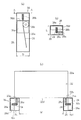
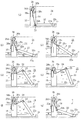
- FIG. 1 It is the schematic block diagram of the floating type flap gate which the applicant proposed previously, (a) is the figure seen from the side surface, (b) is the figure seen from the front. It is a figure explaining the principle of operation of the floating type flap gate which the applicant proposed previously, (a) shows the initial stage of flooding, (b) shows the middle stage of standing, (c) shows the late stage of standing, and (d) shows the initial stage of lodging.
- FIG. 1 shows the schematic block diagram of the floating type flap gate which the applicant proposed previously, (a) is the figure seen from the side surface, (b) is the figure seen from the front. It is a figure explaining the principle of operation of the floating type flap gate which the applicant proposed previously, (a) shows the initial stage of flooding, (b) shows the middle stage of standing, (c) shows the late stage of standing, and (d) shows the initial stage of lodging.
- the purpose of the present invention is to allow the door to be installed even when the side door contact becomes large and the aesthetic appearance is not impaired and the storage space for the auxiliary unit such as door operation cannot be secured inside the side door.
- An auxiliary unit for body movement and the like was realized by placing it in a storage body provided at a position opposite to the rope mounting portion on the front end surface of the door body in the lying state.
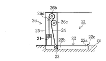
- FIG. 1 is a diagram showing a schematic configuration of a floating flap gate of the present invention.
- reference numeral 21 denotes a floating flap gate of the present invention installed on a road surface rs of an opening of a breakwater or a tide wall, for example.
- the floating flap gate 21 uses the water pressure of water w flowing from the ocean (or river) to the living space or underground space, and uses the rotating shaft 22c of the base end side 22a as a fulcrum to support the distal end side 22b of the door body 22.
- the opening is oscillated to block the opening in a watertight state.
- the floating flap gate 21 of the present invention has one end of a wire rope 24 attached to the front end surface 22 d of the door body 22.
- brackets 23 are attached to, for example, both sides of the front end surface 22d of the door body 22, and one end of the wire rope 24 is attached to these brackets 23. Yes.
- the other end of the wire rope 24 is drawn into a slit 25a provided on the front surface of the storage body 25 provided at a position facing the bracket 23 on the front end surface 22d of the door body 22 when lying down.
- the slit 25a can be blocked by a rubber plate 27 having a cut 27a in parallel with the slit 25a, thereby preventing dust and the like from entering the housing 25. .
- a door body operation provided with a counterweight 26a, a pulley group composed of two upper and lower constant pulleys 26b and 26c, and a stopper 26d that defines the upper limit of the counterweight 26a, etc.
- Auxiliary unit 26 is associatedly arranged.
- the other end of the wire rope 24 drawn in from the slit 25a of the housing 25 is wound around the upper fixed pulley 26b from the lower fixed pulley 26c, and then attached to the counterweight 26a.
- the weight 26a is suspended.
- the two upper and lower fixed pulleys 26b and 26c guide the wire rope 24, and the counterweight 26a is at its lowest point when the inclination angle ⁇ with respect to the horizontal surface of the door body 22 during the standing or lying down is a predetermined angle. Install in such a position. According to the investigation results of the inventors, it has been found that there is no problem if the inclination angle ⁇ of the predetermined angle is in the range of 15 ° to 60 °.
- the fixed pulley 26c positioned below determines the installation position so that the counterweight 26a contacts the stopper 26d when the door body 22 reaches the standing limit (see FIG. 2A).
- the installation position may be determined so that the counterweight 26a does not contact the stopper 26d as shown in FIG. 2B. However, the counterweight 26a closely contacts the stopper 26d.
- the installation position may be determined.
- the length from one end of the wire rope 24 to the end of winding of the wire rope 24 around the fixed pulley 26c positioned below is The installation position of the fixed pulley 26c is determined so that the length (B2 + A2) at the time of standing up is longer than the length (B1 + A1) at the time.
- the fixed pulley 26c is installed so that the length (B1 + A1) when lying down and the length (B2 + A2) when standing up are the same. Determine the position.
- the installation position of the upper fixed pulley 26b is made into a low position, and the door body 22 is maintained. Can be supported at a predetermined standing limit (angle). Moreover, the lift of the counterweight 26a is securable by installing the upper fixed pulley 26b in a high position.
- the shape of the counterweight 26a and the installation position relationship between the counterweight 26a and the pulley group are not limited to those shown in FIGS. 1 and 2, but may be those exemplified in FIGS.
- FIG. 3 shows two lower fixed pulleys 26c constituting the pulley group, and the counterweight 26a is moved up and down between the upper fixed pulleys 26b (column type).
- this column type even if the same counterweight 26a as in FIGS. 1 and 2 is used, the depth D of the storage body 25 for storing the auxiliary unit 26 for door operation, etc. (the length in the left-right direction in FIG. 3A) ) Can be shortened.
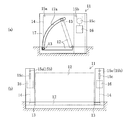
- FIG. 4 is a rectangular parallelepiped shape thinner than the counterweight 26a shown in FIGS. 1 and 2, and the door body width direction length L of the storage body 25 for storing the auxiliary unit 26 for door operation, etc. (FIG. 4B). (Length in the vertical direction of the paper) is reduced (thin). In the case of this thin shape, the interval W (see FIG. 4C) between the storage bodies 25 for storing the auxiliary units 26 such as the door body operation that makes a pair can be widened when the door body 22 is lying down.
- FIG. 5 shows a state in which the counterweight 26a shown in FIGS. 1 and 2 is recessed relative to the lower fixed pulley 26c, and the lower fixed pulley 26c can be inserted into the recessed portion (compact). Type). In the case of this compact type, even if it is the same type as in FIGS. 1 and 2, the depth D of the storage body 25 that stores the auxiliary unit 26 for door operation, etc. can be shortened.
- the guide surfaces of the wire ropes 24 of the upper constant pulley 26b and the lower constant pulley 26c are arranged in the same direction. However, as shown in FIG.
- the guide surface of the wire rope 24 of the fixed pulley 26b and the lower fixed pulley 26c may be arranged at an angle (wide type).
- the floating-type flap gate 21 of the present invention arranges the auxiliary unit 26 such as the door body operation inside the storage body 25 provided at a relative position to the rope mounting portion of the distal end surface 22d of the door body 22 in the lying state, A storage space for the auxiliary unit 26 such as door operation is not required on the side of the door 22.
- the floating flap gate 21 can be installed even in a place where the side door contact with the storage space for the auxiliary unit 26 such as door operation cannot be installed, and in some cases, the existing wall is used as the side wall. It is also possible to do.
- the floating flap gate 21 of the present invention does not impair the aesthetic appearance because the wire rope 24 is housed inside the housing body 25 when the door body 22 falls down.
- the door unit operation auxiliary unit 26 constituting the floating flap gate 21 of the present invention may not have the configuration shown in FIGS.
- a compression coil spring 31 may be attached instead of the counterweight 26a.
- the compression coil spring 31 When the compression coil spring 31 is used, for example, when the inclination angle ⁇ of the door body 22 is 30 °, the compression coil spring 31 has a natural length as shown in FIG. Install so that the turning force in the direction is minimized. Then, when the door body 22 is lying down or standing up, the compression coil spring 31 is compressed as shown in FIG. 9B so that the turning force of the door body 22 in the standing direction or the lying down direction is maximized. To do.
- the tension coil spring 32 is used instead of the compression coil spring 31, the inclination angle ⁇ of the door body 22 is 30 ° so that the tension coil spring 32 has a natural length as shown in FIG. In addition, when the door body 22 is lying down or standing up, the tension coil spring 32 is extended as shown in FIG.
- the compression coil spring 31 or the tension coil spring 32 is not limited to a linear coil spring as shown in FIGS. 9 and 10, but a taper coil spring, a conical coil spring, a drum coil spring, a barrel coil spring, an unequal coil spring, and the like.
- a spring having nonlinear characteristics such as a pitch coil spring may be used.
- a first compression spring having a large diameter and a short length a second compression spring having a medium diameter and a medium length, and a third compression spring having a small diameter and a long length are included.
- a combination coil spring may be used to make the tensile force non-linear.
- the second compression spring and the third compression spring return to the normal dimension, and all three compression springs return to the natural length.
- the third compression spring, the second compression spring, and the first compression spring are sequentially contracted from the middle of standing to the completion of standing of the door body, and all three compression springs are contracted when the standing is completed. Note that when lying down, it is the opposite of when standing up.
- wire rope 24 is used in the above embodiment, fiber ropes such as polyamide, polyester, polyethylene, polypropylene, aramid, polyarylate, and ultrahigh density polyethylene may be used. .
- the floating flap gate 21 of the present invention is installed in the opening of the breakwater or the tide wall.
- the installation location of the floating flap gate 21 of the present invention is the opening of the breakwater or the tide wall.
- it can be installed at the entrance of a facility or underground passage.
Landscapes
- Engineering & Computer Science (AREA)
- Structural Engineering (AREA)
- General Engineering & Computer Science (AREA)
- Mechanical Engineering (AREA)
- Civil Engineering (AREA)
- Barrages (AREA)
Abstract
美観を損なうことなく、扉体の起立補助・起立完了時の衝撃吸収・倒伏時の水位追従機構の収納スペースを側部戸当り内部に確保できない場合も設置できるようにする。 防波堤又は防潮壁の開口部或いは出入口に設置され、扉体22の先端側22bが基端側22aの回転軸22cを支点として起立揺動可能に構成した浮体式フラップゲート21である。一端を扉体22の先端面22dに、他端にカウンタウエイト26aを取り付けたワイヤロープ24を案内し、扉体22の傾斜角θが所定角度になった時にカウンタウエイト26aが最下点となるように定滑車26b,26cを設置した、扉体22の起立補助・起立完了時の衝撃吸収・倒伏時の水位追従機構26を、倒伏状態の扉体22の先端面22dのワイヤロープ24の取付け部と相対する位置に設けた収納体25内に配置する。
Description
本発明は、増水時に、増水した水が生活空間や地下空間に流れ込まないようにするため、例えば防波堤や防潮壁の開口部に設置した扉体を浮上させて前記開口部を遮断する浮体式フラップゲートに関するものである。
増水時に、増水した水が生活空間や地下空間に流れ込まないようにするため、流入しようとする水の浮力を利用し、基端側の回転軸を支点として扉体を浮上させ、例えば防波堤や防潮壁の開口部を遮断する浮体式フラップゲートがある(例えば特許文献1)。
しかしながら、特許文献1で開示された浮体式フラップゲートは、流入初期の水の速度が速い場合には扉体1の浮上動作が遅れ、生活空間や地下空間に越流する問題がある(図11(a)参照)。
また、水位の低下時、扉体1は、扉体1の1/3程度の高さの水位までは起立状態を維持し、その後急激に倒伏するという危険な挙動を示す(図11(b)参照)。
前記問題点の内、流入初期の越流を防ぐために、一端にカウンタウエイトを取付けたロープの他端を、滑車を介して扉体に繋いだ浮体式フラップゲートが提案されている(例えば特許文献2)。
この特許文献2で提案された浮体式フラップゲートは、カウンタウエイトの重さで浮体式フラップゲートの浮力不足を補うことで、流入初期の扉体の浮上動作の遅れを解決している。
しかしながら、特許文献2で提案された浮体式フラップゲートは、常時、扉体の浮上動作を助ける方向にカウンタウエイトの重さを作用させるので、水位低下時の倒伏がし難くなる。
そこで、出願人は、流入初期に扉体の浮上動作が遅れて生活空間や地下空間へ越流することがなく、また、水位低下時にも倒伏がし難くなることがなく、かつ急激に倒伏するという危険な挙動もない浮体式フラップゲートを提案した(特許文献3)。
この浮体式フラップゲート11は、例えば図12に示すように、扉体12の先端側両側面に設置したロッド13にロープ14の一端を取り付け、ロープ14の他端を定滑車15a,15b及びカウンタウエイト16を取り付けた動滑車15cを介して側部戸当り17に固定した構成である。
そして、起立途中又は倒伏途中で、扉体12の水平面に対する傾斜角θが例えば45°になった時に、前記カウンタウエイト16が最下点となるよう、前記定滑車15aを設置している。
上記構成の浮体式フラップゲート11の場合、増水による扉体12の起立時、水平面に対する傾斜角θが45°になるまでは、扉体12はカウンタウエイト16によって起立方向に引っ張られて起立を補助される(図13(a)(b)参照)。そして、傾斜角θが45°を超えると、カウンタウエイト16が抵抗となって扉体12の起立速度が減速する(図13(c)参照)。
一方、水位低下による扉体12の倒伏時は、傾斜角θが45°になるまでは、扉体12はカウンタウエイト16によって倒伏方向に引っ張られ、低下する水位への追従を補助される(図13(d)参照)。そして、傾斜角θが45°より小さくなると、カウンタウエイト16が抵抗となって扉体12の倒伏速度が減速する。
ところで、前記浮体式フラップゲート11では、側部戸当り17に形成したガイド孔17aに前記ロッド13を貫通させ、側部戸当り17の内部空間に、定滑車15a,15b及び動滑車15cやカウンタウエイト16を設置している。前記ガイド孔17aは扉体12の起立限のストッパも兼ねている。
しかしながら、側部戸当り17の内部空間に定滑車15a,15b及び動滑車15cやカウンタウエイト16を設置する場合、以下の問題を内在することになる。
定滑車、動滑車、カウンタウエイトの設置、及び動滑車とカウンタウエイトの移動を可能とする内部空間が必要であるため、側部戸当りが大きくなって美観が損なわれる。一方、側部戸当りに前記内部空間を確保できない場合は、設置することができない。
本発明が解決しようとする問題点は、滑車群、カウンタウエイトの設置、及びカウンタウエイトの移動を可能とする空間を側部戸当りの内部に形成する場合は、側部戸当りが大きくなって美観を損なうという点である。一方、側部戸当りの内部に前記空間を確保できない場合は、設置することができないという点である。
本発明は、側部戸当りが大きくなって美観を損なうことがなく、滑車群、カウンタウエイトの設置、及びカウンタウエイトの移動を可能とする空間を側部戸当りの内部に確保できない場合も設置できるようにすることを目的としてなされたものである。
本発明は、
防波堤又は防潮壁の開口部或いは出入口に設置され、水が流入する際、前記開口部或いは前記出入口を遮断するために、前記流入する水の方向に、高さ方向の平面内で扉体の先端側が基端側の回転軸を支点として起立揺動が可能なように構成した浮体式フラップゲートであって、
前記扉体の先端面に一端を取り付けたロープと、
前記ロープの他端に取り付けられたカウンタウエイト又はばねと、
前記ロープを案内し、起立途中又は倒伏途中における扉体の水平面に対する傾斜角が所定角度になった時に前記カウンタウエイトが最下点又は前記ばねが自然長となるように設置した滑車群と、
を少なくとも有する、扉体の起立補助・起立完了時の衝撃吸収・倒伏時の水位追従機構を、倒伏状態における前記扉体の先端面の前記ロープの取付け部と相対する位置に設けた収納体内に配置したことを最も主要な特徴としている。
防波堤又は防潮壁の開口部或いは出入口に設置され、水が流入する際、前記開口部或いは前記出入口を遮断するために、前記流入する水の方向に、高さ方向の平面内で扉体の先端側が基端側の回転軸を支点として起立揺動が可能なように構成した浮体式フラップゲートであって、
前記扉体の先端面に一端を取り付けたロープと、
前記ロープの他端に取り付けられたカウンタウエイト又はばねと、
前記ロープを案内し、起立途中又は倒伏途中における扉体の水平面に対する傾斜角が所定角度になった時に前記カウンタウエイトが最下点又は前記ばねが自然長となるように設置した滑車群と、
を少なくとも有する、扉体の起立補助・起立完了時の衝撃吸収・倒伏時の水位追従機構を、倒伏状態における前記扉体の先端面の前記ロープの取付け部と相対する位置に設けた収納体内に配置したことを最も主要な特徴としている。
上記の本発明では、扉体の起立補助・起立完了時の衝撃吸収・倒伏時の水位追従機構を、倒伏状態における扉体の先端面のロープ取付け部と相対する位置に設けた収納体内に配置するので、扉体の側部に前記機構の収納スペースが不要になる。以下、扉体の起立補助・起立完了時の衝撃吸収・倒伏時の水位追従機構を、扉体動作等補助ユニットという。
本発明では、起立又は倒伏途中における扉体の水平面に対する傾斜角が所定角度のときを分岐点として、扉体の起立又は倒伏の補助となったり、起立又は倒伏の抵抗となったりする。従って、流入初期の越流や倒伏完了前の急激な倒伏を防止でき、また、起立完了時の衝撃を緩和できるのと共に、倒伏初期には水位ヘの追従性が良くなる。
また、本発明では、起立完了時に、カウンタウエイト及びロープによって扉体に作用する水圧荷重を支持するので、扉体の起伏揺動を案内するガイド孔を省略することができる。
また、本発明では、扉体動作等補助ユニットを倒伏状態における扉体の先端面のロープ取付け部と相対する位置に設けた収納体内に配置するので、扉体の側部に扉体動作等補助ユニットの収納スペースが不要になる。従って、側部戸当りが設置できない場所であっても設置可能になり、場合によっては、既設壁を側壁として使用することも可能である。
本発明は、側部戸当りが大きくなって美観を損なうことがなく、扉体動作等補助ユニットの収納スペースを側部戸当りの内部に確保できない場合も設置できるようにするという目的を、扉体動作等補助ユニットを、倒伏状態における扉体の先端面のロープ取付け部と相対する位置に設けた収納体内に配置することで実現した。
本発明を実施するための形態を、図1~図10を用いて詳細に説明する。
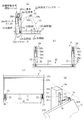
図1は本発明の浮体式フラップゲートの概略構成を示した図である。
図1は本発明の浮体式フラップゲートの概略構成を示した図である。
図1において、21は例えば防波堤や防潮壁の、開口部の路面rsに設置される本発明の浮体式フラップゲートである。この浮体式フラップゲート21は、海洋(或いは河川)から生活空間や地下空間に流入する水wの水圧を利用して、基端側22aの回転軸22cを支点として扉体22の先端側22bを起立揺動させ、開口部を水密状態に遮断するものである。
本発明の浮体式フラップゲート21は、図1に示すように、扉体22の先端面22dにワイヤロープ24の一端を取付けている。この扉体22の先端面22dへのワイヤロープ24の取付け例として、図1では、扉体22の先端面22dの例えば両側にブラケット23を取付け、これらブラケット23にワイヤロープ24の一端を取付けている。このワイヤロープ24の他端は、倒伏時の扉体22の先端面22dの、前記ブラケット23と相対する位置に設けた収納体25の前面に設けたスリット25aから内部に引き込まれている。
なお、前記スリット25aは、図1(d)のように、スリット25aと平行に切り目27aを入れたゴム板27で塞いでおくことで、収納体25の内部への塵などの侵入を防止できる。
前記収納体25の内部には、例えば、カウンタウエイト26aと、上下2個の定滑車26b,26cからなる滑車群と、前記カウンタウエイト26aの上昇限を規定するストッパ26dを備えた扉体動作等補助ユニット26が関連配置されている。
そして、収納体25のスリット25aから内部に引き込まれた前記ワイヤロープ24の他端は、下方の定滑車26cから上方の定滑車26bに巻き回された後、カウンタウエイト26aに取り付けられて、カウンタウエイト26aを吊り下げている。
前記上下2個の定滑車26b,26cは、前記ワイヤロープ24を案内し、起立途中又は倒伏途中における扉体22の水平面に対する傾斜角θが所定角度になった時に前記カウンタウエイト26aが最下点となるような位置に設置する。なお、発明者らの調査結果によれば、前記所定角度の傾斜角θは15°~60°の範囲であれば問題がないことが分かっている。
つまり、下方に位置する定滑車26cは、扉体22が起立限になった時にカウンタウエイト26aがストッパ26dに当接するように、その設置位置を決定する(図2(a)参照)。一方、倒伏時には、図2(b)のように、カウンタウエイト26aがストッパ26dに当接しないように、その設置位置を決定してもよいが、カウンタウエイト26aがストッパ26dにぴったり当接するように、その設置位置を決定してもよい。
すなわち、倒伏時に、カウンタウエイト26aがストッパ26dに当接しない図2の場合は、ワイヤロープ24の一端から、下方に位置する定滑車26cへのワイヤロープ24の巻き付け終了までの長さが、倒伏時の前記長さ(B1+A1)よりも起立限時の前記長さ(B2+A2)が長くなるように、前記定滑車26cの設置位置を決定する。一方、倒伏時に、カウンタウエイト26aがストッパ26dにぴったり当接する場合は、倒伏時の前記長さ(B1+A1)と起立限時の前記長さ(B2+A2)が同じになるように、前記定滑車26cの設置位置を決定する。
このようにすることで、扉体22の起立限位置を保ったまま、1個の定滑車とする場合に比べて、上方の定滑車26bの設置位置を低い位置にすることなく、扉体22を所定の起立限(角度)で支持することができる。また、上方の定滑車26bを高い位置に設置することで、カウンタウエイト26aの揚程を確保することができる。
このカウンタウエイト26aの形状や、カウンタウエイト26aと滑車群の設置位置関係は、図1,2に示したものに限らず、図3~図6に例示したものでも良い。
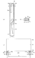
図3は、滑車群を構成する下方の定滑車26cを2個とし、上方の定滑車26bとの間でカウンタウエイト26aを昇降動させるものである(柱型)。この柱型の場合、図1,2と同じカウンタウエイト26aを使用しても、扉体動作等補助ユニット26を収納する収納体25の奥行きD(図3(a)の紙面左右方向の長さ)を短くすることができる。
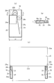
図4は、図1,2に示したカウンタウエイト26aよりも薄形の直方体状として、扉体動作等補助ユニット26を収納する収納体25の扉体幅方向長さL(図4(b)の紙面上下方向の長さ)を短くしたものである(薄型)。この薄型の場合、扉体22の倒伏時、対をなす扉体動作等補助ユニット26を収納する収納体25間の間隔W(図4(c)参照)を広くすることができる。
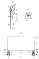
図5は、図1,2に示したカウンタウエイト26aの、下方の定滑車26cとの相対部分を凹ませ、当該凹ませた部分に下方の定滑車26cを挿入可能としたものである(コンパクト型)。このコンパクト型の場合、図1,2と同タイプであっても、扉体動作等補助ユニット26を収納する収納体25の奥行きDを短くすることができる。
図1~図5の例では、上方の定滑車26bと下方の定滑車26cのワイヤロープ24の案内面が同じ方向となるように配置しているが、図6に示したように、上方の定滑車26bと下方の定滑車26cのワイヤロープ24の案内面が角度をなして配置したものでも良い(幅広型)。
本発明の浮体式フラップゲート21は、倒伏状態にある扉体22の先端面22dのロープ取付け部との相対位置に設けた収納体25の内部に扉体動作等補助ユニット26を配置するので、扉体22の側部に扉体動作等補助ユニット26の収納スペースが不要になる。
従って、扉体動作等補助ユニット26の収納スペースを有する側部戸当りが設置できない場所であっても浮体式フラップゲート21を設置することが可能になり、場合によっては、既設壁を側壁として使用することも可能である。
また、本発明の浮体式フラップゲート21は、扉体22の倒伏時にはワイヤロープ24が収納体25の内部に収納されているので、美観が損なわれることがない。
上記構成の本発明の浮体式フラップゲート21では、扉体22の起立時、及び扉体22の倒伏時は、以下に説明するような作用を奏する。
(扉体22の起立時:図7(a)~(e))
浸水初期は、(a)図に示す出水前の倒伏状態から、カウンタウエイト26aが降下し、扉体22は起立方向に引っ張られて起立を補助される((b)図参照)。そして、水平面に対する扉体22の傾斜角θが例えば30°になると、扉体22とワイヤロープ24が一直線になり((c)図参照)、カウンタウエイト26aは最下端の位置となる。
浸水初期は、(a)図に示す出水前の倒伏状態から、カウンタウエイト26aが降下し、扉体22は起立方向に引っ張られて起立を補助される((b)図参照)。そして、水平面に対する扉体22の傾斜角θが例えば30°になると、扉体22とワイヤロープ24が一直線になり((c)図参照)、カウンタウエイト26aは最下端の位置となる。
水平面に対する扉体22の傾斜角θが30°を超えると、扉体22の起立揺動によりカウンタウエイト26aが上昇するので、カウンタウエイト26aが抵抗となって扉体22の起立速度を減速し((d)図参照)、起立完了時((e)図参照)の衝撃力を緩和する。
(起立状態の扉体22の倒伏時:図7(f),(g))
倒伏初期は、カウンタウエイト26aが下降し、扉体22は倒伏方向に引っ張られて水位の低下に追従して倒伏する((f)図参照)。そして、水平面に対する扉体22の傾斜角θが例えば30°になると、扉体22とワイヤロープ24が一直線になり、カウンタウエイト26aは最下端の位置となる((c)と同じ状態)。
倒伏初期は、カウンタウエイト26aが下降し、扉体22は倒伏方向に引っ張られて水位の低下に追従して倒伏する((f)図参照)。そして、水平面に対する扉体22の傾斜角θが例えば30°になると、扉体22とワイヤロープ24が一直線になり、カウンタウエイト26aは最下端の位置となる((c)と同じ状態)。
水平面に対する扉体22の傾斜角θが例えば30°より小さくなると、扉体22の倒伏によりカウンタウエイト26aが上昇するので、カウンタウエイト26aが抵抗となって扉体22の倒伏速度を減速し((g)図参照)、倒伏完了時((a)図と同じ状態)の衝撃力を緩和する。
本発明の浮体式フラップゲート21を構成する扉体動作等補助ユニット26は、図1~図6に示した構成でなくても良い。
例えば、図8に示すように、カウンタウエイト26aの代わりに、圧縮コイルばね31を取り付けても良い。
圧縮コイルばね31を使用する場合、例えば扉体22の傾斜角θが30°の時に、図9(a)に示すように圧縮コイルばね31が自然長となるようにして、ばねによる扉体起立方向の旋回力が最小となるように設置する。そして、扉体22の倒伏時又は起立限時に、図9(b)に示すように圧縮コイルばね31が圧縮されて、扉体22の起立方向又は倒伏方向の旋回力が最大となるように設置する。
一方、圧縮コイルばね31に代えて引張りコイルばね32を使用する場合は、扉体22の傾斜角θが30°で、図10(a)に示すように引張りコイルばね32が自然長となるようにし、扉体22の倒伏時又は起立限時に、図10(b)に示すように引張りコイルばね32が伸ばされるようにする。
前記圧縮コイルばね31或いは引張りコイルばね32は、図9や図10に示したような線形のコイルばねに限らず、テーパコイルばね、円錐形コイルばね、鼓形コイルばね、樽形コイルばね、不等ピッチコイルばねのような非線形特性を有するばねを使用しても良い。
また、軸中心側から順番に、例えば大径で長さの短い第1の圧縮ばね、中径で長さが中間の第2の圧縮ばね、小径で長さの長い第3の圧縮ばねからなる組合せコイルばねを用いて引張力を非線形とするものでも良い。
この組合せコイルばねでは、扉体の倒伏時では、3つの圧縮ばねが全て縮んでいる状態である。そして、扉体の起立初期から起立前期までは、3つの圧縮ばねがそれぞれ伸び始め、起立前期になると第1の圧縮ばねが元の性質に戻る。
次に、起立前期から扉体の起立中期までは、第2の圧縮ばねと第3の圧縮ばねが順次元の性質に戻り、3つの圧縮ばね全てが自然長に戻る。
起立中期から扉体の起立完了までは、第3の圧縮ばね、第2の圧縮ばね、第1の圧縮ばねが順次縮んでいき、起立完了時には3つの圧縮ばねが全て縮んだ状態になる。
なお、倒伏時は前記起立時と逆になる。
なお、倒伏時は前記起立時と逆になる。
本発明は、前記の例に限るものではなく、各請求項に記載の技術的思想の範疇であれば、適宜実施の形態を変更しても良いことは言うまでもない。
例えば、前記実施例では、ワイヤロープ24を使用しているが、ポリアミド系、ポリエステル系、ポリエチレン系、ポリプロピレン系、アラミド系、ポリアリレート系、超高密度ポリエチレンなどの繊維ロープを使用しても良い。
また、上記の例では本発明の浮体式フラップゲート21を防波堤や防潮壁の開口部に設置する場合について説明したが、本発明の浮体式フラップゲート21の設置場所は防波堤や防潮壁の開口部に限らず、施設や地下通路の入口等に設置することもできる。
21 浮体式フラップゲート
22 扉体
22a 基端側
22b 先端側
22c 回転軸
22d 先端面
24 ワイヤロープ
25 収納体
26 扉体動作等補助ユニット
26a カウンタウエイト
26b、26c 定滑車
31 圧縮コイルばね
32 引張りコイルばね
22 扉体
22a 基端側
22b 先端側
22c 回転軸
22d 先端面
24 ワイヤロープ
25 収納体
26 扉体動作等補助ユニット
26a カウンタウエイト
26b、26c 定滑車
31 圧縮コイルばね
32 引張りコイルばね
Claims (3)
- 防波堤又は防潮壁の開口部或いは出入口に設置され、水が流入する際、前記開口部或いは前記出入口を遮断するために、前記流入する水の方向に、高さ方向の平面内で扉体の先端側が基端側の回転軸を支点として起立揺動が可能なように構成した浮体式フラップゲートであって、
前記扉体の先端面に一端を取り付けたロープと、
前記ロープの他端に取り付けられたカウンタウエイトと、
前記ロープを案内し、起立途中又は倒伏途中における扉体の水平面に対する傾斜角が所定角度になった時に前記カウンタウエイトが最下点となるように設置した滑車群と、
を少なくとも有する、扉体の起立補助・起立完了時の衝撃吸収・倒伏時の水位追従機構を、倒伏状態における前記扉体の先端面の前記ロープの取付け部と相対する位置に設けた収納体内に配置したことを特徴とする浮体式フラップゲート。 - 前記カウンタウエイトに代えて、ロープの他端にばねを取付け、前記傾斜角が所定角度になった時にばねが自然長となるように滑車群を設置したことを特徴とする請求の範囲第1項に記載の浮体式フラップゲート。
- 前記滑車群は、少なくとも2個の定滑車を有するものであることを特徴とする請求の範囲第1項又は第2項に記載の浮体式フラップゲート。
Applications Claiming Priority (2)
| Application Number | Priority Date | Filing Date | Title |
|---|---|---|---|
| JP2012-275870 | 2012-12-18 | ||
| JP2012275870A JP6158503B2 (ja) | 2012-12-18 | 2012-12-18 | 浮体式フラップゲート |
Publications (1)
| Publication Number | Publication Date |
|---|---|
| WO2014097712A1 true WO2014097712A1 (ja) | 2014-06-26 |
Family
ID=50978062
Family Applications (1)
| Application Number | Title | Priority Date | Filing Date |
|---|---|---|---|
| PCT/JP2013/077502 Ceased WO2014097712A1 (ja) | 2012-12-18 | 2013-10-09 | 浮体式フラップゲート |
Country Status (3)
| Country | Link |
|---|---|
| JP (1) | JP6158503B2 (ja) |
| TW (1) | TWI593857B (ja) |
| WO (1) | WO2014097712A1 (ja) |
Cited By (3)
| Publication number | Priority date | Publication date | Assignee | Title |
|---|---|---|---|---|
| JP2016108883A (ja) * | 2014-12-09 | 2016-06-20 | 日立造船株式会社 | 陸上型浮体式フラップゲート |
| JP2016113847A (ja) * | 2014-12-17 | 2016-06-23 | 日立造船株式会社 | 陸上型浮体式フラップゲート |
| JP2021070989A (ja) * | 2019-10-31 | 2021-05-06 | 日立造船株式会社 | 起伏ゲート式防波堤 |
Families Citing this family (4)
| Publication number | Priority date | Publication date | Assignee | Title |
|---|---|---|---|---|
| JP6461699B2 (ja) * | 2015-04-28 | 2019-01-30 | 日立造船株式会社 | 浮体式フラップゲート |
| JP6696681B2 (ja) * | 2016-03-23 | 2020-05-20 | 日立造船株式会社 | 浮体式フラップゲート設備 |
| US9879394B2 (en) * | 2017-06-19 | 2018-01-30 | Keith Lorin Jenkins | Herodotus machine |
| JP7215929B2 (ja) * | 2019-02-26 | 2023-01-31 | 日立造船株式会社 | 起伏ゲートの設置方法および起伏ゲート |
Citations (3)
| Publication number | Priority date | Publication date | Assignee | Title |
|---|---|---|---|---|
| JP2001214425A (ja) * | 2000-02-02 | 2001-08-07 | Nippon Frp Kk | 建造物出入口の流入水遮断用フローゲート及びそのロック装置 |
| JP2003253912A (ja) * | 2002-03-01 | 2003-09-10 | Kumagai Gumi Co Ltd | 水位追従式起伏ゲート装置 |
| JP2012241449A (ja) * | 2011-05-20 | 2012-12-10 | Hitachi Zosen Corp | 浮体式フラップゲート |
-
2012
- 2012-12-18 JP JP2012275870A patent/JP6158503B2/ja active Active
-
2013
- 2013-10-09 WO PCT/JP2013/077502 patent/WO2014097712A1/ja not_active Ceased
- 2013-11-01 TW TW102139680A patent/TWI593857B/zh active
Patent Citations (3)
| Publication number | Priority date | Publication date | Assignee | Title |
|---|---|---|---|---|
| JP2001214425A (ja) * | 2000-02-02 | 2001-08-07 | Nippon Frp Kk | 建造物出入口の流入水遮断用フローゲート及びそのロック装置 |
| JP2003253912A (ja) * | 2002-03-01 | 2003-09-10 | Kumagai Gumi Co Ltd | 水位追従式起伏ゲート装置 |
| JP2012241449A (ja) * | 2011-05-20 | 2012-12-10 | Hitachi Zosen Corp | 浮体式フラップゲート |
Cited By (4)
| Publication number | Priority date | Publication date | Assignee | Title |
|---|---|---|---|---|
| JP2016108883A (ja) * | 2014-12-09 | 2016-06-20 | 日立造船株式会社 | 陸上型浮体式フラップゲート |
| JP2016113847A (ja) * | 2014-12-17 | 2016-06-23 | 日立造船株式会社 | 陸上型浮体式フラップゲート |
| JP2021070989A (ja) * | 2019-10-31 | 2021-05-06 | 日立造船株式会社 | 起伏ゲート式防波堤 |
| JP7148477B2 (ja) | 2019-10-31 | 2022-10-05 | 日立造船株式会社 | 起伏ゲート式防波堤 |
Also Published As
| Publication number | Publication date |
|---|---|
| TWI593857B (zh) | 2017-08-01 |
| JP2014118774A (ja) | 2014-06-30 |
| TW201430191A (zh) | 2014-08-01 |
| JP6158503B2 (ja) | 2017-07-05 |
Similar Documents
| Publication | Publication Date | Title |
|---|---|---|
| KR101680172B1 (ko) | 부체식 플랩 게이트 | |
| WO2014097712A1 (ja) | 浮体式フラップゲート | |
| US9011042B2 (en) | Floating body connection-type flap gate | |
| KR102466645B1 (ko) | 부체식 플랩 게이트 | |
| JP6625911B2 (ja) | フラップゲート及びゲート設備 | |
| JP6461699B2 (ja) | 浮体式フラップゲート | |
| JP2013253381A (ja) | 浮体式フラップゲート | |
| JP6117280B2 (ja) | 浮体式フラップゲート | |
| JP2005330011A (ja) | 浮屋根式貯蔵タンクのスロッシング抑制機構 | |
| JP6767916B2 (ja) | 起伏ゲート | |
| JP6435455B2 (ja) | 陸上型浮体式フラップゲート | |
| JP6438555B2 (ja) | 浮体式フラップゲート | |
| JP5271840B2 (ja) | ゲート装置 | |
| JP2006008147A (ja) | スロッシング抑制装置 | |
| JP6696681B2 (ja) | 浮体式フラップゲート設備 | |
| JP2013064300A (ja) | 自立型高潮防扉の扉体構造 | |
| HK1174371B (en) | Floating body type flap gate | |
| JP2015209714A (ja) | 浮体式フラップゲート | |
| JP2017160593A (ja) | 陸上型フラップゲート設備 |
Legal Events
| Date | Code | Title | Description |
|---|---|---|---|
| 121 | Ep: the epo has been informed by wipo that ep was designated in this application |
Ref document number: 13863916 Country of ref document: EP Kind code of ref document: A1 |
|
| NENP | Non-entry into the national phase |
Ref country code: DE |
|
| WWE | Wipo information: entry into national phase |
Ref document number: IDP00201503723 Country of ref document: ID |
|
| 122 | Ep: pct application non-entry in european phase |
Ref document number: 13863916 Country of ref document: EP Kind code of ref document: A1 |