WO2014097646A1 - Dispositif de gestion d'énergie et système de gestion d'énergie - Google Patents
Dispositif de gestion d'énergie et système de gestion d'énergie Download PDFInfo
- Publication number
- WO2014097646A1 WO2014097646A1 PCT/JP2013/007508 JP2013007508W WO2014097646A1 WO 2014097646 A1 WO2014097646 A1 WO 2014097646A1 JP 2013007508 W JP2013007508 W JP 2013007508W WO 2014097646 A1 WO2014097646 A1 WO 2014097646A1
- Authority
- WO
- WIPO (PCT)
- Prior art keywords
- unit
- allowable
- power
- air quality
- devices
- Prior art date
Links
Images


Classifications
-
- H—ELECTRICITY
- H02—GENERATION; CONVERSION OR DISTRIBUTION OF ELECTRIC POWER
- H02J—CIRCUIT ARRANGEMENTS OR SYSTEMS FOR SUPPLYING OR DISTRIBUTING ELECTRIC POWER; SYSTEMS FOR STORING ELECTRIC ENERGY
- H02J3/00—Circuit arrangements for ac mains or ac distribution networks
- H02J3/12—Circuit arrangements for ac mains or ac distribution networks for adjusting voltage in ac networks by changing a characteristic of the network load
- H02J3/14—Circuit arrangements for ac mains or ac distribution networks for adjusting voltage in ac networks by changing a characteristic of the network load by switching loads on to, or off from, network, e.g. progressively balanced loading
-
- H—ELECTRICITY
- H02—GENERATION; CONVERSION OR DISTRIBUTION OF ELECTRIC POWER
- H02J—CIRCUIT ARRANGEMENTS OR SYSTEMS FOR SUPPLYING OR DISTRIBUTING ELECTRIC POWER; SYSTEMS FOR STORING ELECTRIC ENERGY
- H02J2310/00—The network for supplying or distributing electric power characterised by its spatial reach or by the load
- H02J2310/50—The network for supplying or distributing electric power characterised by its spatial reach or by the load for selectively controlling the operation of the loads
- H02J2310/56—The network for supplying or distributing electric power characterised by its spatial reach or by the load for selectively controlling the operation of the loads characterised by the condition upon which the selective controlling is based
- H02J2310/62—The condition being non-electrical, e.g. temperature
- H02J2310/64—The condition being economic, e.g. tariff based load management
-
- Y—GENERAL TAGGING OF NEW TECHNOLOGICAL DEVELOPMENTS; GENERAL TAGGING OF CROSS-SECTIONAL TECHNOLOGIES SPANNING OVER SEVERAL SECTIONS OF THE IPC; TECHNICAL SUBJECTS COVERED BY FORMER USPC CROSS-REFERENCE ART COLLECTIONS [XRACs] AND DIGESTS
- Y02—TECHNOLOGIES OR APPLICATIONS FOR MITIGATION OR ADAPTATION AGAINST CLIMATE CHANGE
- Y02B—CLIMATE CHANGE MITIGATION TECHNOLOGIES RELATED TO BUILDINGS, e.g. HOUSING, HOUSE APPLIANCES OR RELATED END-USER APPLICATIONS
- Y02B70/00—Technologies for an efficient end-user side electric power management and consumption
- Y02B70/30—Systems integrating technologies related to power network operation and communication or information technologies for improving the carbon footprint of the management of residential or tertiary loads, i.e. smart grids as climate change mitigation technology in the buildings sector, including also the last stages of power distribution and the control, monitoring or operating management systems at local level
- Y02B70/3225—Demand response systems, e.g. load shedding, peak shaving
-
- Y—GENERAL TAGGING OF NEW TECHNOLOGICAL DEVELOPMENTS; GENERAL TAGGING OF CROSS-SECTIONAL TECHNOLOGIES SPANNING OVER SEVERAL SECTIONS OF THE IPC; TECHNICAL SUBJECTS COVERED BY FORMER USPC CROSS-REFERENCE ART COLLECTIONS [XRACs] AND DIGESTS
- Y04—INFORMATION OR COMMUNICATION TECHNOLOGIES HAVING AN IMPACT ON OTHER TECHNOLOGY AREAS
- Y04S—SYSTEMS INTEGRATING TECHNOLOGIES RELATED TO POWER NETWORK OPERATION, COMMUNICATION OR INFORMATION TECHNOLOGIES FOR IMPROVING THE ELECTRICAL POWER GENERATION, TRANSMISSION, DISTRIBUTION, MANAGEMENT OR USAGE, i.e. SMART GRIDS
- Y04S20/00—Management or operation of end-user stationary applications or the last stages of power distribution; Controlling, monitoring or operating thereof
- Y04S20/20—End-user application control systems
- Y04S20/222—Demand response systems, e.g. load shedding, peak shaving
-
- Y—GENERAL TAGGING OF NEW TECHNOLOGICAL DEVELOPMENTS; GENERAL TAGGING OF CROSS-SECTIONAL TECHNOLOGIES SPANNING OVER SEVERAL SECTIONS OF THE IPC; TECHNICAL SUBJECTS COVERED BY FORMER USPC CROSS-REFERENCE ART COLLECTIONS [XRACs] AND DIGESTS
- Y04—INFORMATION OR COMMUNICATION TECHNOLOGIES HAVING AN IMPACT ON OTHER TECHNOLOGY AREAS
- Y04S—SYSTEMS INTEGRATING TECHNOLOGIES RELATED TO POWER NETWORK OPERATION, COMMUNICATION OR INFORMATION TECHNOLOGIES FOR IMPROVING THE ELECTRICAL POWER GENERATION, TRANSMISSION, DISTRIBUTION, MANAGEMENT OR USAGE, i.e. SMART GRIDS
- Y04S50/00—Market activities related to the operation of systems integrating technologies related to power network operation or related to communication or information technologies
- Y04S50/10—Energy trading, including energy flowing from end-user application to grid
Definitions
- the present invention relates to an energy management device that manages the amount of power used by a consumer, and an energy management system that uses the energy management device.
- Japanese Patent Application Publication No. 2010-259186 (hereinafter referred to as “Document 1”) describes a control system that performs a reserved operation based on hourly electricity rate information.
- the control system starts the operation of the first electric device when a predetermined start time is reached, and when the first electric device operates more than an allowable value, the first electric device is set to a low power consumption operation, Start operation of the second electrical equipment.
- this control system exceeds the contract power and allowable power by changing the timing of operating the electrical devices so that the time periods when the power consumption is large do not overlap.
- the breaker is prevented from being shut off.
- the allowable value in the configuration described in Document 1 is defined by a charge amount of about 80% for charging, and a time of about 3 hours for a clothes dryer.
- This technology aims to reduce electricity charges by operating electrical equipment during times when the unit price of electricity is as low as possible, and it is possible to control peak power by adjusting the operation schedule of electrical equipment. .
- An object of the present invention is to provide an energy management device capable of suppressing an increase in the total amount of electricity charges while allowing the device to operate in a time zone when the unit price of electricity charges is high, and An object of the present invention is to provide an energy management system using this energy management apparatus.
- An energy management device includes an instruction unit that instructs each of a plurality of devices about an operating state, a power acquisition unit that acquires power used by the plurality of devices, and a unit time determined for each time zone
- the upper limit of the amount of power per unit is set as an allowable power amount for each time zone, and the sum of the power amounts used by the plurality of devices is set in the permissible value setting unit for each time zone
- a management processing unit that determines operating states of the plurality of devices that are instructed from the instruction unit so as to be maintained within the range of the allowable power amount.
- a charge setting unit in which an upper limit target value is set as an allowable charge for an electricity charge in a predetermined period, a charge table storage part for storing an electricity charge unit price for each time zone, and a setting in the charge setting part
- a calculation unit that calculates the allowable power amount for each time period from the permissible charge and the unit price of the electricity price for each time period stored in the charge table storage unit, and the allowable value setting unit includes: It is preferable to store the allowable power amount calculated by the calculation unit.
- the plurality of devices include a plurality of environment improvement devices that contribute to improvement of indoor air quality
- the management processing unit operates at least one of the plurality of environment improvement devices. Selecting an environment improvement device that can operate with available power that is within the range of the allowable power amount and excluding the power used by other devices, and setting the operating state to the selected environment improvement device. It is preferable to indicate.
- an air quality acquisition unit that acquires measurement data from a device that measures indoor air quality, and a plurality of target values for the measurement data acquired by the air quality acquisition unit are set as allowable contamination levels.
- a target value setting unit wherein the management processing unit selects the permissible contamination level for each step determined for the available power, and the higher the available power, the better the indoor air quality. Selecting the allowable contamination level at a certain stage, selecting an environment improvement device capable of operating with the available power so that the measurement data is close to the selected allowable contamination level, and selecting the selected environment It is preferable to indicate the operating state to the improvement device.
- the management processing unit is configured to provide the plurality of environmental improvement devices during a period in which the measurement data that is even better than the stage in which the indoor air quality is the best among the allowable contamination degree is obtained. During the period when the measurement data is obtained that is even worse than the stage where the indoor air quality is the lowest among the allowable dirt levels, the indoor air quality is improved regardless of the available power. It is further preferable to select an environmental improvement device having a high effect and to indicate an operating state of the selected environmental improvement device.
- the management processing unit calculates power consumption by the at least one environment improvement device from the available power. It is further preferable to operate another device with the remaining power that is excluded.
- the air quality acquisition unit acquires indoor air quality measured for each room by the device for a plurality of rooms, and the management processing unit has a priority for the air quality in the room. It is more preferable to assign the available power in order from the environmental improvement devices arranged in the room with the higher priority.
- the energy management apparatus further includes a communication interface unit that acquires a unit price of electricity charge for each time zone by communication with another device, and the charge table storage unit stores the electricity charge for each time zone obtained by the communication interface unit. It is preferable to store the unit price.
- An energy management system includes the above-described energy management device and a measurement device that measures electric power used by the plurality of devices.
- the allowable power amount that is the upper limit of the power amount per unit time is determined for each time zone, and the total amount of power used by the device for each time zone is maintained within the range of the allowable power amount. Since the operation state of the device is determined as described above, there is an advantage that it is possible to suppress an increase in the total amount of the electricity bill while allowing the device to operate in a time zone when the unit price of the electricity bill is high. .
- the embodiment described below assumes an energy management system configured as shown in FIG.
- the energy management system includes an energy management device 10 having a function of instructing an operation state to each of a plurality of devices 30 and a measuring device 20 that measures electric power used by the plurality of devices 30.
- This energy management system is used in a consumer who purchases electric power from an electric power company.
- the electric power company is represented by an electric power company, but may be another power generation company.
- This type of electric power provider may set the unit price of electricity according to the time zone when selling electricity. For example, many electric power companies have prepared a charge system that varies the unit price of electricity during the day when the demand for power is relatively high and during the night when the demand for power is relatively low. In this type of charge system, the unit price of electricity charges may be divided into about 3 to 4 levels per day.
- the electricity unit price is divided into three stages for each time zone.
- the numerical values described below are examples for helping understanding, and are not intended to be limited to these values.
- the types of the plurality of devices 30 are also exemplified, the type of the plurality of devices 30 is not intended to be limited.
- the plurality of devices 30 may be arbitrary devices 30 used by consumers, but it is desirable to include devices 30 that improve indoor air quality (IAQ).
- IAQ indoor air quality
- Indoor air quality relates to the quality of air for a healthy and comfortable life, and targets various environmental factors. More specifically, environmental factors are classified into chemical factors, biological factors, and physical factors.
- Chemical factors include carbon dioxide, volatile organic compounds (VOC), and odor components
- biological factors include house dust and pollen
- physical factors include temperature and humidity.
- House dust means mold, viruses, tick droppings, pet skin pieces, and the like.
- the indoor air quality includes dust and dust in addition to the environmental factors described above.
- the physical factor may include light, sound, electromagnetic waves, and the like.
- environmental factors related to indoor air quality are assumed to be temperature, humidity, carbon dioxide, house dust, pollen, odor, VOC, dust, and dust.
- an air quality sensor 21 is provided as a measuring device that measures these environmental factors with a single device.
- the air quality sensor 21 is not limited to the configuration that measures the environmental factors described above.
- An air quality sensor 21 that measures environmental factors according to the purpose is used.
- the equipment 30 that improves indoor air quality is assumed to be an air purifier 31 and a ventilation equipment 32, as well as an air conditioning equipment 33 that adjusts temperature and humidity.
- these devices 30 are collectively referred to as “environment improvement devices”.
- the environmental improvement device is typically an air purifier 31, a ventilation facility 32, or an air conditioning facility 33, but may be a device 30 such as a device for dispersing charged water particulates in the air, a humidifier, or a dehumidifier. Good.
- Each device 30 used in the consumer including the environmental improvement device has a function of communicating with the energy management apparatus 10.
- the energy management apparatus 10 communicates with each device 30 to instruct the operation state to each device 30 and obtains the operation state from each device 30. That is, the energy management device 10 is a device that controls and monitors each device 30 and functions as a so-called HEMS (Home Energy Management System) controller.
- HEMS Home Energy Management System
- the energy management apparatus 10 may acquire the amount of power used by each device 30 from each device 30.
- the communication path between the energy management apparatus 10 and each device 30 is assumed to be a wireless communication path using radio waves as a transmission medium. However, this communication path can be shared by a power distribution network that supplies power to each device 30 at the consumer, and a dedicated communication line can also be used. When the distribution network is also used as a communication path, communication between the energy management apparatus 10 and each device 30 is performed using a power line carrier communication technique.
- the measuring device 20 has a function of measuring the power consumption of the main circuit of the distribution board 22 and the power consumption of each branch circuit branched in the distribution board 22.
- the power usage of the main circuit may be obtained as the sum of power usage for each branch circuit.
- the measurement device 20 includes a housing separate from the distribution board 22.
- the measuring device 20 is disposed adjacent to the distribution board 22. Since the housing of the measuring device 20 is separated from the distribution board 22, it becomes possible to install the measuring device 20 by retrofitting in an existing consumer provided with the distribution board 22.
- the measuring device 20 may be configured to be housed in the distribution board 22.
- the measuring device 20 may be configured such that the power used for each outlet can be measured in addition to the power used for each branch circuit.
- the energy management device 10 has a function of acquiring the power measured by the measurement device 20 through communication.
- the communication path between the energy management apparatus 10 and the measurement apparatus 20 employs a wired communication path in the illustrated example, but a wireless communication path can also be employed.
- the energy management apparatus 10 and the measurement apparatus 20 perform serial communication using the wired communication path L1 of the RS-485 (EIA-485) standard.
- the energy management apparatus 10 includes a communication interface unit (hereinafter referred to as “communication I / F unit”) 111 that performs communication with the measurement device 20 and a communication I / F unit 112 that performs communication with a plurality of devices 30. .
- the energy management apparatus 10 further includes a communication I / F unit 113 that transmits information between at least the display device 41 and the operation device 42.
- the energy management apparatus 10 in the illustrated example includes a communication I / F unit 114 for connecting to the communication network NT1.
- the communication I / F unit 114 preferably has a specification corresponding to Ethernet (registered trademark).
- a broadband router 43 is connected to the communication I / F unit 114.
- various devices used by customers and a telecommunication network NT2 such as the Internet are connected to the broadband router 43.
- a television receiver 44, a personal computer 45, and a hub 46 are described as examples.
- a network camera 47 is connected to the hub 46.
- the energy management apparatus 10 can communicate with various web servers 50 that provide various services through the telecommunication network NT2. Services provided by this type of web server 50 include provision of information such as a weather forecast or predicted temperature, a function update of the energy management apparatus 10, a service for starting a smartphone or a tablet terminal described later, and the like. In some cases, a power reduction request or the like may be received from a web server 50 managed by an electric power company or a service providing company outsourced by the electric power company. In the illustrated example, only one web server 50 is described, but actually, there are a plurality of web servers 50 in response to provision of services and requests to the energy management apparatus 10.
- the illustrated energy management apparatus 10 is capable of notifying the user of information through the television receiver 44 or the personal computer 45 and acquiring an image photographed by the network camera 47.
- the personal computer 45 is also used for maintenance of the energy management apparatus 10.
- the illustrated configuration is an example, and elements constituting the system are not limited to the illustrated example.
- the display device 41 and the operation device 42 may be a display operation device that is integrally provided with a flat panel display and a touch switch. Further, the display device 41 and the operation device 42 may be configured to include a housing different from the energy management device 10 in addition to the configuration provided integrally with the energy management device 10.
- the display operation device is a portable communication device 401 such as a smartphone or a tablet terminal. There may be.
- the display operation of the communication device 402 is performed using a function of using the mobile telephone network in a portable communication device 402 such as a smartphone or a tablet terminal as a communication path. It can also be used as a device.
- the energy management apparatus 10 includes, as main hardware elements, a device including a processor that realizes a configuration described below by executing a program and devices that configure the communication I / F units 111 to 114.
- a device including a processor is selected from a microcomputer incorporating a memory, a CPU that requires a separate memory, and the like.
- the program is normally stored in the memory before shipment from the factory, but the program is acquired through the telecommunication network NT2, or the program stored in the readable recording medium is read into the memory. May be adopted.
- the energy management device 10 operates in the power acquisition unit 12 that acquires power used by the plurality of devices 30 from the measurement device 20 through the communication I / F unit 111 and the operation state of each of the plurality of devices 30 through the communication I / F unit 112. And an instruction unit 13 for instructing.
- the power acquisition unit 12 acquires power information indicating the power used by the plurality of devices 30.
- the power acquisition unit 12 may also use the power usage acquired from the plurality of devices 30 when the power usage of the plurality of devices 30 can be acquired from the plurality of devices 30 through the communication I / F unit 112.
- the power of the plurality of devices 30 acquired by the power acquisition unit 12 from the measuring device 20 is actually not the instantaneous power but the power amount for each specified sampling time.
- the sampling time for the power acquisition unit 12 to acquire power is appropriately selected from 30 seconds, 1 minute, 5 minutes, and the like. If the sampling time for acquiring power is short, the amount of information increases and the processing load increases, and if the sampling time for acquiring power is long, the accuracy of power management decreases, so the sampling time should be selected as described above. Is desirable.
- the power acquisition unit 12 acquires the power used for each branch circuit from the measurement device 20.
- the power acquisition unit 12 uses the relationship between the operation state instructed by the instruction unit 13 to the plurality of devices 30 through the communication I / F unit 112 and the change in power for each branch circuit acquired from the measurement device 20. It also has a function for obtaining power consumption corresponding to the operation every 30. That is, the power acquisition unit 12 learns the power consumption corresponding to the operation for each device 30.
- the air conditioner 33 has large fluctuations in power consumption due to external factors such as indoor / outdoor air temperature difference, room thermal insulation performance, presence / absence of indoor heat source even at the same set temperature. .
- the power consumption in the period from when the air conditioner 33 starts up until the room temperature approaches the set temperature is significantly larger than the power consumption after reaching the set temperature. Therefore, it is desirable for the air conditioning equipment 33 to use an average value of power consumption in a period from when the room temperature starts until the room temperature approaches the set temperature and a period after the room temperature reaches the set temperature.
- the allowable value setting unit 14 in which the allowable power amount is set for each time zone, and the total power amount used by the plurality of devices 30 for each time zone is maintained within the allowable power amount range. And a management processing unit 15 that determines the operating state of the device 30 that is instructed from the instruction unit 13.
- the permissible power set in the permissible value setting unit 14 is the upper limit of the permissible power per unit time, and the management processing unit 15 per unit time consumed by the plurality of devices 30 used in the consumer.
- the operation of at least one device 30 is determined so that the total amount of power does not exceed the allowable power amount.
- the allowable value setting unit 14 divides a predetermined period into a plurality of time zones, and an allowable power amount is set for each time zone.
- the predetermined period may be one day or one year. The predetermined period is not limited to the above.
- the allowable power amount is set according to the time zone.
- the time zone does not mean only the time zone that divides the day, but the division of day of the week or season may be included in the concept of the time zone. That is, the management processing unit 15 maintains the total amount of power per unit time used by the plurality of devices 30 for each time period within the allowable power amount set in the allowable value setting unit 14. The operating state of the device 30 instructed from the instruction unit 13 among the plurality of devices 30 is determined.
- the allowable power amount for each time zone set in the allowable value setting unit 14 can be set as appropriate. However, in the present embodiment, the allowable power amount is set based on the target value of the upper limit of the electricity bill set by the consumer and the electricity bill unit price for each time zone.
- Electricity unit price is acquired by communication with other devices through the communication I / F unit 114.
- Other devices that communicate through the communication I / F unit 114 are appropriately selected from, for example, a web server managed by an electric power company, a web server managed by a service provider outsourced by an electric power company, and the like.
- the other device is an external device other than the energy management device 10.
- the electricity bill unit price for each time zone acquired by the communication I / F unit 114 by communication with other devices is stored in the fee table storage unit 161.
- the contents of the charge table storage unit 161 can be updated, and the operation of the system can be maintained in response to the change in the electricity charge by updating the contents of the charge table storage part 161 with the change in the electricity charge.
- the unit price of electricity charges stored in the charge table storage unit 161 may be input using the operation device 42.
- the target value for the upper limit of electricity charges is set for a predetermined period.
- an upper limit is set for the electricity charge used by the consumer for a predetermined period such as one month, three months, or one year.
- the management processing unit 15 controls the operation of each device 30 with the goal of not exceeding this upper limit.
- the period for setting the target value for the upper limit of electricity charges can be set as appropriate. For example, it may be one week, but in order to facilitate comparison with the electricity charges charged by the electric power company, It is desirable to set a period.
- the energy management apparatus 10 includes a fee setting unit 162 in which an allowable fee is set.
- the allowable charge is set in the charge setting unit 162 by the user at the consumer using the operation device 42.
- the energy management apparatus 10 obtains an allowable fee set as a recommended value by communicating with a web server managed by an electric power company or a web server managed by a service provider, and sets it in the charge setting unit 162. It is also possible to do.
- the permissible power amount for each time zone set in the permissible value setting unit 14 is obtained by using the unit price of the electricity rate for each time zone stored in the rate table storage unit 161 and the permissible rate set in the rate setting unit 162. Calculated by the calculation unit 160.
- the calculation unit 160 divides the allowable fee by 30 days, which is the number of days in a month, and further divides it by 24 hours, which is the number of hours in a day. That is, the calculation unit 160 calculates a fee per hour from the allowable fee set for the predetermined period.
- the calculation unit 160 calculates the amount of power that can be used per unit time (that is, one hour) for each time zone from the unit price of electricity bill for each time zone, with the hourly charge obtained from the allowable fee as the upper limit. .
- the electric energy calculated in this way is stored in the allowable value setting unit 14 as the allowable electric energy.
- the calculation unit 160 obtains a charge per unit time from the allowable charge set for the predetermined period, and calculates the amount of electric power corresponding to this charge as the allowable electric energy using the unit price of the electric charge.
- the predetermined period is one month
- the allowable charge is 7200 yen
- the unit time is one hour
- the unit price of electricity bill for each time zone stored in the charge table storage unit 161 has the relationship shown in FIG. .
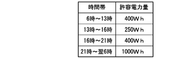
- Calculating unit 160 first obtains a charge per unit time from the allowable charge. That is, 7200 yen is divided by 30 days, and further divided by 24 hours. As a result, the electricity bill per unit time (in this example, 1 hour) is 10 yen. On the other hand, since the unit price of electricity charges has the relationship shown in FIG. 2, the amount of power that can be used per unit time (allowable power amount) is obtained for each time zone, and the relationship shown in FIG. 3 is obtained.
- the allowable power amount obtained as described above is stored in the allowable value setting unit 14 and is used when the management processing unit 15 determines the operation of the device 30.
- the management processing unit 15 In order for the management processing unit 15 to perform the above-described calculation, it is necessary to determine the amount of power that is expected to be consumed by the device 30, and the processing load may increase. In order to simplify the processing, when the management processing unit 15 tries to start the operation of one of the devices (first device) 30, the power consumption of the device (second device) 30 that is already operating And the power to be allocated to the first device 30 that is to start a new operation may be determined based on this power consumption. That is, the management processing unit 15 sets the average value of the allowable power amount as the allowable power, and uses the available power obtained by subtracting the power consumption acquired by the power acquisition unit 12 from the allowable power to the device 30 that is about to start an operation. assign.
- the allowable power which is an average value of the allowable power amount, becomes 250 W, and the new device (first device) 30 at 21:00.
- the allowable power becomes 1000 W. Therefore, if the power consumption of the other device (second device) 30 is 200 W at 13:00, the available power is 50 W, and the power consumption of the other device (second device) 30 is 200 W at 21:00. In some cases, the available power is 800W.
- the plurality of devices 30 include a plurality of environment improvement devices as described above.
- each environment improvement device can select two types of air purifier 31 and ventilation facility 32, and air purifier 31 can select two types of operation states of weak operation and strong operation.
- the power consumption of the air cleaner 31 is 100 W in the weak operation, 300 W in the strong operation, and the power consumption of the ventilation facility 32 is 50 W.
- both the air purifier 31 and the ventilation facility 32 have an effect of improving the indoor air quality, and the degree of the improvement effect is higher as the power consumption is larger.
- the effect of improving the indoor air quality is greatest when the operation of the air purifier 31 is a strong operation, and the case where the operation of the air purifier 31 is a weak operation is sub-optimal.
- the ventilation equipment 32 When the ventilation equipment 32 is operated, it is minimized.
- the operation of the environmental improvement device starts at 13:00 and 21:00 under the conditions described above. Since the available power is 50 W at 13:00, only the ventilation facility 32 can be operated. However, since the available power is 1000 W at 21:00, the environment improvement device can be operated in any manner.
- the air purifier 31 is operated in a strong operation by giving the constraint that the effect of improving the indoor air quality is maximized and the operation of only one environmental improvement device is started.
- the power consumption of the consumer at this time is 500 W by adding 300 W that is the power consumption of the air purifier 31 to 200 W that is the power consumption of the other device 30. If there is no restriction condition, it is possible to use the air cleaner 31 and the ventilation facility 32 together. In this case, the power consumption at the consumer is 550 W.
- the management processing unit 15 can select the type of environmental improvement device depending on the amount of available power, as in the above-described example, the environmental improvement is performed in consideration of improvement of indoor air quality and reduction of power consumption. It has a function to determine the operating state of the equipment.
- the energy management device 10 includes an air quality acquisition unit 171 as shown in FIG. 4 in order to acquire predetermined measurement data from the air quality sensor 21 as a measurement device that measures indoor air quality.
- the air quality sensor 21 is communicable with the energy management apparatus 10 similarly to the device 30, and it is assumed that a wireless communication path using radio waves as a transmission medium is used as the communication path.
- the communication path between the energy management apparatus 10 and the air quality sensor 21 may be a wired communication path that uses the power distribution network as a communication path or a wired communication path that uses a dedicated communication line.
- the distribution network is also used as a communication path, communication is performed between the energy management device 10 and the air quality sensor 21 using the power line carrier communication technology.
- the air quality sensor 21 can measure a plurality of types of environmental factors related to indoor air quality.
- the energy management device 10 pays attention to at least one of environmental factors measured by the air quality sensor 21, and the air quality acquisition unit 171 receives measurement data from the air quality sensor 21 through the communication I / F unit 112 for the environmental factor. To get.
- the energy management apparatus 10 includes a target value setting unit 172 in which an allowable contamination level that is a target value for the measurement data of environmental factors acquired by the air quality acquisition unit 171 from the air quality sensor 21 is set.
- the target value setting unit 172 has a plurality of levels of allowable contamination.
- the allowable stain level is two stages of an upper limit value and a lower limit value is taken as an example.
- the management processing unit 15 selects an allowable contamination level as a target value from the target value setting unit 172 according to the available power, and further selects an environment improvement device so as to approach the selected allowable contamination level, and selects the selected environment Determine the operating status of the improvement device.
- the management processing unit 15 selects a level of allowable dirt level for each stage determined for the available power, and the management processing unit 15 is in a stage where the indoor air quality is better as the available power is larger. Select an acceptable stain level.
- the management processing unit 15 selects the first environment improvement device that can operate with available power from among the plurality of environment improvement devices 31 to 33 so that the measurement data approaches the selected allowable dirt level. And instructing the selected first environmental improvement device on the operating state.
- the management processing unit 15 can select the strong operation of the air purifier 31 that has the greatest effect of improving the indoor air quality only in a time zone in which the available power exceeds 500 W, and performs ventilation in other time zones. The selection of only the facility 32 is allowed.
- the management processing unit 15 has a low allowable contamination level from the target value setting unit 172 (that is, the indoor air quality is good). Select the allowable stain level (lower limit).
- the management processing unit 15 has a large allowable dirt level from the target value setting unit 172 (that is, the indoor air quality is inferior) when an environment improvement device having a low effect of improving the indoor air quality is selected. Select the permissible stain level (upper limit).
- the ventilation equipment 32 can be selected from 6:00 to 21:00, and the air cleaner 31 can be operated strongly from 21:00 to the next 6:00. That is, the relationship between the time zone, the type and operating state of the environmental improvement device, and the allowable contamination level is as shown in FIG. Even if the time zone is from 21:00 to next 6:00, if the power consumption by another device 30 such as a water heater is large, the ventilation facility 32 is selected as the environment improvement device or the air purifier is used. The weak operation of the machine 31 is selected.
- the management processing unit 15 selects an allowable contamination level from the target value setting unit 172 for each level determined for the available power. That is, the management processing unit 15 selects an allowable contamination level at a stage where the indoor air quality is better as the available power is larger. Furthermore, the management processing unit 15 selects an environment improvement device that can operate within the range of available power, and the measurement data acquired from the air quality sensor 21 using this environment improvement device is the selected allowable contamination level. Instruct the selected environmental improvement device about the driving state so that
- the measurement data when operating an environmental improvement device that has a high effect of improving indoor air quality, the measurement data may fall below the minimum allowable contamination level, and an environmental improvement device that has a low effect of improving indoor air quality is low. When operated, the measurement data may continue to exceed the maximum allowable dirt level. In the former state, power is consumed wastefully from the viewpoint of energy saving, and in the latter state, the effect of improving the indoor air quality by the environmental improvement device is poor.
- the management processing unit 15 stops power consumption by stopping the environmental improvement device during the period when the measurement data that is better than the stage where the indoor air quality is the best in the allowable dirt level is obtained. It is desirable to have a function to suppress. In addition, the management processing unit 15 improves the indoor air quality regardless of the available power during a period in which measurement data that is worse than the stage in which the indoor air quality is the lowest among the allowable dirt levels is obtained. It is desirable to have a function for enhancing the indoor air quality improvement effect by selecting an environmental improvement device having a high effect. An example of operation when this function is added to the management processing unit 15 is shown.
- the management processing unit 15 normally installs the ventilation equipment 32 with the power consumption of 50 W. Decide to work.
- the management processing unit 15 determines the operating state of the device 30 so that the air purifier 31 operates in a weak operation. To do. At this time, from the viewpoint of energy saving, it is desirable to stop the ventilation facility 32. However, when priority is given to the effect of improving the indoor air quality, it is also possible to arrange to continue the operation of the ventilation facility 32. Moreover, here, although the determination which operates the air cleaner 31 by a weak operation is performed, you may perform the determination which operate
- the management processing unit 15 stops the air cleaner 31 and restarts the operation of the ventilation facility 32. Determine the action to be performed. That is, the energy management apparatus 10 returns to a normal operation for suppressing the electricity bill.
- the management processing unit 15 normally operates the air purifier 31 with strong operation.
- the management processing unit 15 determines to stop the environment improvement device.
- the management processing unit 15 operates the air cleaner 31 in a weak operation according to the level of allowable contamination. It is possible to sequentially select the step of operating the air conditioner and the step of operating the ventilation facility 32. As described above, if the environment improvement device having the effect of improving the indoor air quality is selected in order as the measurement data acquired from the air quality sensor 21 approaches the lower limit of the allowable dirt level, the indoor air quality is improved. The effect is obtained and it also contributes to energy saving.
- the energy management apparatus 10 instructs the operation state of all the devices 30 has been described. However, at least some of the devices 30 are operated by the user in the consumer. It is possible. In particular, since the device 30 that is operated by the user's operation is considered to have been operated by the user to obtain comfort, it is for the user that the energy management device 10 changes the operation of the device 30. It may not be desirable.
- the environmental improvement device that is operating due to the user's operation regardless of the instruction from the energy management device 10 among the devices 30 sets a flag in the management processing unit 15, and the energy management device 10 It is desirable to exclude from control. That is, an environment improvement device that is operating as a result of a user's operation is handled as an operating device 30 when the energy management apparatus 10 calculates available power.
- the environmental improvement device with the flag set operates in preference to the other devices 30.
- the environment improvement device since the environment improvement device is operating by the user, it is usually unnecessary to operate other environment improvement devices, but if there is a surplus in the available power, other environment improvement devices It is also possible to use devices together.
- the environmental improvement device operates as a result of user operation. If the conditions shown in FIG. 3 are used, the allowable power amount is 250 Wh in the time zone from 13:00 to 16:00. Here, it is assumed that the ventilation facility 32 is operating and is consuming 50 W of power, and that the total power consumption by the device 30 measured by the measuring device 20 is 200 W.
- the management processing unit 15 causes the air cleaner 31 to operate in a weak operation in preference to the other devices 30.
- the management processing unit 15 stops the ventilation facility 32. In this case, since the total power consumption becomes 250 W due to the stop of the ventilation facility 32, the allowable power amount in the corresponding time zone is satisfied.
- the measurement data regarding the air quality in the room is within the range between the upper limit value and the lower limit value set as the allowable contamination level, and the lower limit of the allowable contamination level.
- the state below the value is notified to the user by the notification lamp or the indicator 41.
- the light source of the notification lamp is selected from, for example, a light emitting diode, an OLED (Organic Light-Emitting Diode).
- the air quality sensor 21 When a plurality of rooms are provided in a building that uses the energy management system described above, it is desirable to arrange the air quality sensor 21 for each room. However, it is not required that the air quality sensor 21 is provided in every room. In this case, the air quality sensor 21 measures the indoor air quality in units of rooms, and the air quality acquisition unit 171 acquires measurement data relating to the indoor air quality in units of rooms. The correspondence between the air quality sensor 21 and the room is stored in advance in a storage unit (not shown).
- an air quality sensor 21 is arranged in the first room and the second room for a building including three rooms of a first room, a second room, and a third room, and the priority of the first room is given.
- the operation under the condition that the degree is higher than the priority of the second room will be described as an example. Note that the environmental improvement devices arranged in the third room are not controlled.
- Priority setting example and operation example when priority is set are shown below.
- the allowable power amount is 400 Wh in the time zone from 16:00 to 21:00.
- the total power consumption by the plurality of devices 30 is 200 W.
- indoor air quality measurement data in all rooms is within the range between the upper and lower limits of allowable dirt level, and indoor air quality in all rooms. The case where the measurement data exceeds the upper limit of the allowable dirt level will be described.
- the lower limit value of the allowable contamination level is set as the target value for the first room having a high priority, and priority is given.
- the upper limit value of the allowable dirt level is used as the target value.
- the environment improvement device is stopped for the third room in which the environment improvement device that is not controlled is placed.
- the first room has the highest priority for improvement in terms of indoor air quality with 3 rooms. Therefore, the management processing unit 15 first operates the air cleaner 31 in the first room with a strong operation. At this point in time, the total power consumption is 500 W, so the condition of the allowable power amount is exceeded, but priority is given to improving the indoor air quality. Thereafter, when the indoor air quality is improved and the measurement data is reduced to a specified value, the management processing unit 15 causes the air purifier 31 to operate in a weak operation. At this stage, the total power consumption is 300 W, and the allowable power consumption condition is satisfied. After the measurement data regarding the indoor air quality reaches the lower limit value, the operation shifts to the operation of the ventilation facility 32, and the total power consumption is reduced to 250W.
- the second room has a lower priority for improving the air quality in the room than the first room, the upper limit value of the allowable dirt level is the target value, and the current measurement data regarding the air quality in the room is higher than the upper limit value. small. Therefore, the management processing unit 15 satisfies the energy saving by stopping the environmental improvement device. In addition, since the environment improvement apparatus of a 3rd room is out of control object, an environment improvement apparatus is maintained in the stopped state.
- the upper limit value of the allowable contamination level is determined as the target value for the first room having a high priority.
- the management processing unit 15 causes the air cleaner 31 in the first room to operate with strong operation. Therefore, the total power consumption is 500 W, which exceeds the allowable power amount, but this operation is maintained with priority given to improving the indoor air quality.
- the environment improvement device is stopped in the second room. Since the environmental improvement device in the third room is not controlled, the environmental improvement device is kept stopped.
- the air cleaner 31 in the first room is operated in a weak operation. Since the total power consumption at this time is 300 W, 100 W of usable power is generated. Therefore, the environment improvement device can be operated also in the second room.
- the management processing unit 15 may select whether to operate the air purifier 31 in a weak operation or to operate the ventilation facility 32 according to the available power.
- the priority is determined for each room with respect to the improvement of the indoor air quality, and the energy management apparatus 10 determines the environment for each room. Control the operating status of the improvement equipment. That is, the energy management device 10 contributes to restraining an increase in the electricity bill while improving the indoor air quality.
- the plurality of devices 30 in the configuration example described above include a plurality of environment improvement devices, but even if the environment improvement devices are not included, the allowable power amount determined for each time zone is It is possible to employ a configuration that uses at least one device 30 within the range. In addition, with the above-described configuration, it is possible to suppress the amount of power consumed by the consumer, and it is possible to suppress the electricity bill within a predetermined period within the upper limit target value.
- the energy management apparatus 10 of the present embodiment includes an instruction unit 13, a power acquisition unit 12, an allowable value setting unit 14, and a management processing unit 15.
- the instruction unit 13 instructs the operation state to each of the plurality of devices 30.
- the power acquisition unit 12 acquires power used by the plurality of devices 30.
- the upper limit of the electric energy per unit time determined for each time zone is set as the allowable electric energy for each time zone.
- the management processing unit 15 instructs the instruction unit 13 to maintain the total amount of power used by the plurality of devices 30 within the allowable power range set in the allowable value setting unit 14 for each time period. The operating state of the plurality of devices 30 to be determined is determined.
- the energy management apparatus 10 further includes a fee setting unit 162, a fee table storage unit 161, and a calculation unit 160, and the allowable value setting unit 14 performs the following operations.
- the charge setting unit 162 sets an upper limit target value as an allowable charge for an electricity charge in a predetermined period.
- the charge table storage unit 161 stores the electricity unit price for each time zone.
- the calculation unit 160 calculates the allowable power amount for each time zone from the allowable fee set in the rate setting unit 162 and the unit price of the electricity rate for each time zone stored in the fee table storage unit 161.
- the allowable value setting unit 14 stores the allowable power amount calculated by the calculation unit 160.
- the management processing unit 15 performs the following operation.
- the plurality of devices 30 include a plurality of environment improvement devices 31 to 33 that contribute to the improvement of indoor air quality.
- the management processing unit 15 uses the available power that is within the allowable power amount and excludes the power used by the other devices 30.
- the environmental improvement device capable of the above operation is selected, and the operating state is instructed to the selected environmental improvement device.
- the energy management apparatus 10 further includes an air quality acquisition unit 171 and a target value setting unit 172, and the management processing unit 15 performs the following operations.
- the air quality acquisition unit 171 acquires measurement data from a device (air quality sensor 21) that measures indoor air quality.
- the target value setting unit 172 sets a plurality of target values as the allowable contamination level for the measurement data acquired by the air quality acquisition unit 171.
- the management processing unit 15 selects an allowable contamination level for each level determined for the available power, and selects an allowable contamination level at a level where the indoor air quality is better as the available power is larger.
- the management processing unit 15 selects an environment improvement device that can operate with available power so that the measurement data approaches the selected allowable dirt level, and instructs the selected environment improvement device about the operating state. .
- the management processing unit 15 has a period during which measurement data that is even better than the stage where the indoor air quality is the best among the allowable dirt levels is obtained.
- the plurality of environment improvement devices 31 to 33 are not operated.
- the management processing unit 15 has an effect of improving the indoor air quality regardless of the available power during the period when the measurement data that is worse than the stage where the indoor air quality is the lowest among the allowable dirt levels is obtained. Select a high environmental improvement device and indicate the operating status of the selected environmental improvement device.
- the management processing unit 15 is configured such that when at least one of the plurality of environment improvement devices 31 to 33 is operated by a user operation, the at least one environment Other devices are operated by the remaining power obtained by excluding the power consumed by the improved device from the available power.
- the air quality acquisition unit 171 acquires the indoor air quality measured by the device for each room for a plurality of rooms.
- the management processing unit 15 can set the priority for the air quality in each of the plurality of rooms, and assigns the available power in order from the environment improvement device arranged in the room with the higher priority.
- the energy management apparatus 10 further includes a communication interface unit 114, and the charge table storage unit 161 performs the following operations.
- the communication interface unit 114 acquires the electricity bill unit price for each time zone by communicating with other devices.
- the charge table storage unit 161 stores the electricity rate unit price for each time period acquired by the communication interface unit 114.
- the energy management system of the present embodiment includes the energy management device 10 and the measurement device 20 of the present embodiment.
- the measuring device 20 measures the power used by the plurality of devices 30.
Abstract
L'invention concerne un dispositif de gestion d'énergie (10) qui comprend : une unité d'acquisition de puissance (12) ; une unité d'instruction (13) ; une unité définissant la valeur permissible (14) ; et une unité de traitement de gestion (15). L'unité d'acquisition de puissance (12) acquiert la puissance utilisée par une pluralité de dispositifs (30). L'unité d'instruction (13) dicte un état de fonctionnement à chaque dispositif de la pluralité de dispositifs (30). L'unité définissant la valeur permissible (14) définit une limite supérieure pour la quantité de puissance par unité de temps déterminée pour chaque période comme la quantité de puissance permissible pour chaque période. L'unité de traitement de gestion (15) détermine l'état de fonctionnement des dispositifs (30) dicté par l'unité d'instruction (13) de sorte que la quantité totale de puissance utilisée par les dispositifs (30) pour chaque période est maintenue dans la plage de la quantité de puissance permissible définie par l'unité définissant la valeur permissible (14).
Priority Applications (2)
| Application Number | Priority Date | Filing Date | Title |
|---|---|---|---|
| CN201380062712.XA CN104838554B (zh) | 2012-12-21 | 2013-12-20 | 能量管理装置和能量管理系统 |
| EP13865577.4A EP2937961A4 (fr) | 2012-12-21 | 2013-12-20 | Dispositif de gestion d'énergie et système de gestion d'énergie |
Applications Claiming Priority (2)
| Application Number | Priority Date | Filing Date | Title |
|---|---|---|---|
| JP2012-280231 | 2012-12-21 | ||
| JP2012280231A JP5945851B2 (ja) | 2012-12-21 | 2012-12-21 | エネルギー管理装置、エネルギー管理システム |
Publications (1)
| Publication Number | Publication Date |
|---|---|
| WO2014097646A1 true WO2014097646A1 (fr) | 2014-06-26 |
Family
ID=50978004
Family Applications (1)
| Application Number | Title | Priority Date | Filing Date |
|---|---|---|---|
| PCT/JP2013/007508 WO2014097646A1 (fr) | 2012-12-21 | 2013-12-20 | Dispositif de gestion d'énergie et système de gestion d'énergie |
Country Status (4)
| Country | Link |
|---|---|
| EP (1) | EP2937961A4 (fr) |
| JP (1) | JP5945851B2 (fr) |
| CN (1) | CN104838554B (fr) |
| WO (1) | WO2014097646A1 (fr) |
Cited By (1)
| Publication number | Priority date | Publication date | Assignee | Title |
|---|---|---|---|---|
| CN105703358A (zh) * | 2014-07-11 | 2016-06-22 | 英科德技术股份有限公司 | 用于能量测量的装置、服务器、系统和方法 |
Families Citing this family (11)
| Publication number | Priority date | Publication date | Assignee | Title |
|---|---|---|---|---|
| WO2016051570A1 (fr) * | 2014-10-02 | 2016-04-07 | 三菱電機株式会社 | Purificateur d'air |
| JP6480826B2 (ja) * | 2015-07-30 | 2019-03-13 | アズビル株式会社 | 電力管理装置および方法 |
| JP6614866B2 (ja) * | 2015-09-01 | 2019-12-04 | 日立ジョンソンコントロールズ空調株式会社 | 空気調和システム、空気調和方法、及び制御装置 |
| JP6337861B2 (ja) * | 2015-09-24 | 2018-06-06 | 三菱電機株式会社 | 貯湯式給湯システム |
| JP2017108495A (ja) * | 2015-12-08 | 2017-06-15 | 三菱電機ビルテクノサービス株式会社 | デマンド制御装置及びプログラム |
| US10767878B2 (en) | 2017-11-21 | 2020-09-08 | Emerson Climate Technologies, Inc. | Humidifier control systems and methods |
| US11486593B2 (en) | 2018-04-20 | 2022-11-01 | Emerson Climate Technologies, Inc. | Systems and methods with variable mitigation thresholds |
| US11371726B2 (en) | 2018-04-20 | 2022-06-28 | Emerson Climate Technologies, Inc. | Particulate-matter-size-based fan control system |
| WO2019204792A1 (fr) | 2018-04-20 | 2019-10-24 | Emerson Climate Technologies, Inc. | Commande coordonnée de dispositifs et de systèmes autonomes et de qualité d'air intérieur de bâtiment |
| US11226128B2 (en) | 2018-04-20 | 2022-01-18 | Emerson Climate Technologies, Inc. | Indoor air quality and occupant monitoring systems and methods |
| WO2019204790A1 (fr) | 2018-04-20 | 2019-10-24 | Emerson Climate Technologies, Inc. | Systèmes et procédés avec seuils d'atténuation variable |
Citations (3)
| Publication number | Priority date | Publication date | Assignee | Title |
|---|---|---|---|---|
| JPH08237864A (ja) * | 1995-02-23 | 1996-09-13 | Hitachi Ltd | 使用電力量制御方法および装置 |
| JP2003097841A (ja) * | 2001-09-21 | 2003-04-03 | Sanyo Electric Industries Co Ltd | 空調機の台数制御方法 |
| JP2010259186A (ja) | 2009-04-23 | 2010-11-11 | Panasonic Corp | 制御システムおよびその制御方法、プログラム |
Family Cites Families (5)
| Publication number | Priority date | Publication date | Assignee | Title |
|---|---|---|---|---|
| US20090302994A1 (en) * | 2008-06-10 | 2009-12-10 | Mellennial Net, Inc. | System and method for energy management |
| CN101603702B (zh) * | 2008-06-13 | 2012-03-28 | Tcl集团股份有限公司 | 一种自动调节空气质量的空调器及其调节方法 |
| AU2009290590A1 (en) * | 2008-09-15 | 2012-07-26 | General Electric Company | Energy management of clothes dryer appliance |
| WO2011052956A2 (fr) * | 2009-10-26 | 2011-05-05 | Lg Electronics Inc. | Système de réseau et procédé de commande de celui-ci |
| CN102121740A (zh) * | 2010-01-12 | 2011-07-13 | 珠海格力电器股份有限公司 | 空调器控制系统和控制方法以及空调器 |
-
2012
- 2012-12-21 JP JP2012280231A patent/JP5945851B2/ja active Active
-
2013
- 2013-12-20 WO PCT/JP2013/007508 patent/WO2014097646A1/fr active Application Filing
- 2013-12-20 CN CN201380062712.XA patent/CN104838554B/zh active Active
- 2013-12-20 EP EP13865577.4A patent/EP2937961A4/fr not_active Withdrawn
Patent Citations (3)
| Publication number | Priority date | Publication date | Assignee | Title |
|---|---|---|---|---|
| JPH08237864A (ja) * | 1995-02-23 | 1996-09-13 | Hitachi Ltd | 使用電力量制御方法および装置 |
| JP2003097841A (ja) * | 2001-09-21 | 2003-04-03 | Sanyo Electric Industries Co Ltd | 空調機の台数制御方法 |
| JP2010259186A (ja) | 2009-04-23 | 2010-11-11 | Panasonic Corp | 制御システムおよびその制御方法、プログラム |
Non-Patent Citations (1)
| Title |
|---|
| See also references of EP2937961A4 |
Cited By (3)
| Publication number | Priority date | Publication date | Assignee | Title |
|---|---|---|---|---|
| CN105703358A (zh) * | 2014-07-11 | 2016-06-22 | 英科德技术股份有限公司 | 用于能量测量的装置、服务器、系统和方法 |
| JP2016165209A (ja) * | 2014-07-11 | 2016-09-08 | エンコアード テクノロジーズ インク | 電力需要の管理機能を有するサーバ、通信機器、システムおよび電力使用管理方法 |
| CN105703358B (zh) * | 2014-07-11 | 2019-09-03 | 英科德技术股份有限公司 | 用于能量测量的装置、服务器、系统和方法 |
Also Published As
| Publication number | Publication date |
|---|---|
| CN104838554A (zh) | 2015-08-12 |
| CN104838554B (zh) | 2017-09-05 |
| JP5945851B2 (ja) | 2016-07-05 |
| EP2937961A1 (fr) | 2015-10-28 |
| JP2014124066A (ja) | 2014-07-03 |
| EP2937961A4 (fr) | 2016-03-02 |
Similar Documents
| Publication | Publication Date | Title |
|---|---|---|
| JP5945851B2 (ja) | エネルギー管理装置、エネルギー管理システム | |
| US10950924B2 (en) | Priority-based energy management | |
| RU2521611C2 (ru) | Система и способ снижения потребления электроэнергии | |
| JP5710028B2 (ja) | 能動負荷管理の使用を通じて配分可能な運転用予備力エネルギーキャパシティを推定及び供給するシステム及び方法 | |
| ES2823553T3 (es) | Reinicio controlado del servicio eléctrico dentro de un área de servicio público | |
| JP6249895B2 (ja) | 電力制御システム、方法及び電力制御装置 | |
| JP6004709B2 (ja) | 省エネルギー支援システム、サーバ装置、省エネルギー支援方法及びプログラム | |
| JP5872571B2 (ja) | 電力管理システム、電力管理方法及びネットワークサーバ | |
| JP5788591B2 (ja) | 電力監視装置および電力監視システム | |
| JP6332276B2 (ja) | 電力需給調整装置、電力システム、および電力需給調整方法 | |
| JP2014531183A (ja) | 分散負荷制御に基づく適応型需要応答の提供 | |
| JP5768097B2 (ja) | 情報処理装置及びサービス提供方法 | |
| JP5852949B2 (ja) | 電力需要制御システム及び方法 | |
| JP2014502138A (ja) | 電気エネルギー分配装置 | |
| WO2016002346A1 (fr) | Système de commande de puissance et dispositif de commande de puissance | |
| JP2018153011A (ja) | 電力制御システム | |
| JP2011239569A (ja) | 電力制御システム | |
| JP6116970B2 (ja) | エネルギー管理システム、エネルギー管理装置及びエネルギー管理方法 | |
| JP2016034190A (ja) | 電力管理装置、電力管理方法及びプログラム | |
| JP5852950B2 (ja) | 電力需要制御システム及び方法 | |
| JP2015056975A (ja) | 自家発電電力制御システムおよび情報通信システム | |
| JP2015061395A (ja) | エネルギー利用支援システムとその支援方法及び支援プログラム | |
| WO2019155750A1 (fr) | Dispositif de gestion, appareil, procédé de gestion d'équipement électrique, programme et support de stockage | |
| WO2022071259A1 (fr) | Système et programme de régulation d'énergie | |
| WO2019159904A1 (fr) | Dispositif de commande de puissance électrique, système de commande de puissance électrique et procédé de commande de puissance électrique |
Legal Events
| Date | Code | Title | Description |
|---|---|---|---|
| 121 | Ep: the epo has been informed by wipo that ep was designated in this application |
Ref document number: 13865577 Country of ref document: EP Kind code of ref document: A1 |
|
| WWE | Wipo information: entry into national phase |
Ref document number: 2013865577 Country of ref document: EP |
|
| NENP | Non-entry into the national phase |
Ref country code: DE |
|
| 121 | Ep: the epo has been informed by wipo that ep was designated in this application |
Ref document number: 13865577 Country of ref document: EP Kind code of ref document: A1 |