WO2014097585A1 - 圧力センサとその製造方法 - Google Patents
圧力センサとその製造方法 Download PDFInfo
- Publication number
- WO2014097585A1 WO2014097585A1 PCT/JP2013/007303 JP2013007303W WO2014097585A1 WO 2014097585 A1 WO2014097585 A1 WO 2014097585A1 JP 2013007303 W JP2013007303 W JP 2013007303W WO 2014097585 A1 WO2014097585 A1 WO 2014097585A1
- Authority
- WO
- WIPO (PCT)
- Prior art keywords
- introduction hole
- opening
- pressure
- cavity
- hole
- Prior art date
- Legal status (The legal status is an assumption and is not a legal conclusion. Google has not performed a legal analysis and makes no representation as to the accuracy of the status listed.)
- Ceased
Links
Images




Classifications
-
- G—PHYSICS
- G01—MEASURING; TESTING
- G01L—MEASURING FORCE, STRESS, TORQUE, WORK, MECHANICAL POWER, MECHANICAL EFFICIENCY, OR FLUID PRESSURE
- G01L9/00—Measuring steady of quasi-steady pressure of fluid or fluent solid material by electric or magnetic pressure-sensitive elements; Transmitting or indicating the displacement of mechanical pressure-sensitive elements, used to measure the steady or quasi-steady pressure of a fluid or fluent solid material, by electric or magnetic means
- G01L9/0041—Transmitting or indicating the displacement of flexible diaphragms
- G01L9/0051—Transmitting or indicating the displacement of flexible diaphragms using variations in ohmic resistance
-
- G—PHYSICS
- G01—MEASURING; TESTING
- G01L—MEASURING FORCE, STRESS, TORQUE, WORK, MECHANICAL POWER, MECHANICAL EFFICIENCY, OR FLUID PRESSURE
- G01L13/00—Devices or apparatus for measuring differences of two or more fluid pressure values
- G01L13/06—Devices or apparatus for measuring differences of two or more fluid pressure values using electric or magnetic pressure-sensitive elements
-
- G—PHYSICS
- G01—MEASURING; TESTING
- G01L—MEASURING FORCE, STRESS, TORQUE, WORK, MECHANICAL POWER, MECHANICAL EFFICIENCY, OR FLUID PRESSURE
- G01L19/00—Details of, or accessories for, apparatus for measuring steady or quasi-steady pressure of a fluent medium insofar as such details or accessories are not special to particular types of pressure gauges
- G01L19/0007—Fluidic connecting means
- G01L19/0038—Fluidic connecting means being part of the housing
-
- G—PHYSICS
- G01—MEASURING; TESTING
- G01L—MEASURING FORCE, STRESS, TORQUE, WORK, MECHANICAL POWER, MECHANICAL EFFICIENCY, OR FLUID PRESSURE
- G01L19/00—Details of, or accessories for, apparatus for measuring steady or quasi-steady pressure of a fluent medium insofar as such details or accessories are not special to particular types of pressure gauges
- G01L19/06—Means for preventing overload or deleterious influence of the measured medium on the measuring device or vice versa
- G01L19/0627—Protection against aggressive medium in general
- G01L19/0654—Protection against aggressive medium in general against moisture or humidity
-
- G—PHYSICS
- G01—MEASURING; TESTING
- G01L—MEASURING FORCE, STRESS, TORQUE, WORK, MECHANICAL POWER, MECHANICAL EFFICIENCY, OR FLUID PRESSURE
- G01L9/00—Measuring steady of quasi-steady pressure of fluid or fluent solid material by electric or magnetic pressure-sensitive elements; Transmitting or indicating the displacement of mechanical pressure-sensitive elements, used to measure the steady or quasi-steady pressure of a fluid or fluent solid material, by electric or magnetic means
- G01L9/0041—Transmitting or indicating the displacement of flexible diaphragms
- G01L9/0051—Transmitting or indicating the displacement of flexible diaphragms using variations in ohmic resistance
- G01L9/0052—Transmitting or indicating the displacement of flexible diaphragms using variations in ohmic resistance of piezoresistive elements
- G01L9/0054—Transmitting or indicating the displacement of flexible diaphragms using variations in ohmic resistance of piezoresistive elements integral with a semiconducting diaphragm
-
- B—PERFORMING OPERATIONS; TRANSPORTING
- B29—WORKING OF PLASTICS; WORKING OF SUBSTANCES IN A PLASTIC STATE IN GENERAL
- B29C—SHAPING OR JOINING OF PLASTICS; SHAPING OF MATERIAL IN A PLASTIC STATE, NOT OTHERWISE PROVIDED FOR; AFTER-TREATMENT OF THE SHAPED PRODUCTS, e.g. REPAIRING
- B29C45/00—Injection moulding, i.e. forcing the required volume of moulding material through a nozzle into a closed mould; Apparatus therefor
- B29C45/17—Component parts, details or accessories; Auxiliary operations
- B29C45/26—Moulds
- B29C45/33—Moulds having transversely, e.g. radially, movable mould parts
-
- B—PERFORMING OPERATIONS; TRANSPORTING
- B29—WORKING OF PLASTICS; WORKING OF SUBSTANCES IN A PLASTIC STATE IN GENERAL
- B29L—INDEXING SCHEME ASSOCIATED WITH SUBCLASS B29C, RELATING TO PARTICULAR ARTICLES
- B29L2031/00—Other particular articles
- B29L2031/712—Containers; Packaging elements or accessories, Packages
-
- Y—GENERAL TAGGING OF NEW TECHNOLOGICAL DEVELOPMENTS; GENERAL TAGGING OF CROSS-SECTIONAL TECHNOLOGIES SPANNING OVER SEVERAL SECTIONS OF THE IPC; TECHNICAL SUBJECTS COVERED BY FORMER USPC CROSS-REFERENCE ART COLLECTIONS [XRACs] AND DIGESTS
- Y10—TECHNICAL SUBJECTS COVERED BY FORMER USPC
- Y10T—TECHNICAL SUBJECTS COVERED BY FORMER US CLASSIFICATION
- Y10T29/00—Metal working
- Y10T29/49—Method of mechanical manufacture
- Y10T29/49002—Electrical device making
Definitions
- the present disclosure relates to a pressure sensor in which a sensor chip is mounted on a case in which a pressure introduction hole is formed, and a manufacturing method thereof.
- Patent Document 1 proposes a pressure sensor in which a pressure introduction hole is formed so as to penetrate the case, and a sensor chip that outputs a sensor signal corresponding to the measurement medium is mounted on the case.
- the pressure introduction hole includes a first introduction hole extending in a predetermined direction, and extending in a direction perpendicular to the extension direction of the first introduction hole. It is comprised by the 2nd introduction hole connected with 1 introduction hole. That is, the pressure introducing hole has a so-called L shape.
- the sensor chip is mounted so that the opening of one end of the first introduction hole opposite to the side communicating with the second introduction hole is closed.
- the second introduction hole of the pressure introduction holes is parallel to the top-and-bottom direction, and the opening of the pressure introduction hole opposite to the opening at one end (the first introduction hole of the second introduction holes).
- the member to be attached so that the opening on the side opposite to the side communicating with the ground side becomes the ground side. Then, a sensor signal corresponding to the measurement medium introduced into the pressure introduction hole is output from the sensor chip.
- This disclosure is intended to provide a pressure sensor that can improve the drainage of the pressure introduction hole and a method for manufacturing the same.
- the pressure sensor includes a case and a sensor chip that outputs a sensor signal corresponding to the measurement medium.
- the case is formed with a pressure introduction hole through which the measurement medium is introduced.
- a sensor chip is mounted so as to close the opening at one end of the pressure introducing hole.
- the pressure introduction hole constitutes an opening at one end and a first introduction hole extending in a predetermined direction and an opening at the other end located on the opposite side of the opening at one end and a direction different from the predetermined direction And a second introduction hole that communicates with the first introduction hole.
- the angle formed by the wall surface on the opening side at the other end of the wall surface constituting the first introduction hole and the wall surface of the second introduction hole connected to the wall surface is set to 90 ° or more.
- the second introduction hole is a communication portion that communicates with the first introduction hole between the opening at the other end and the end opposite to the opening at the other end, and a space that extends further beyond the end from the communication portion. Has an increase chamber.
- Such a pressure sensor is used by being attached to a member to be mounted such that, among the pressure introduction holes, the second introduction hole is parallel to the top and bottom direction, and the opening at the other end is on the ground side. Since the space increasing chamber is provided, the length of the second introduction hole is increased in the direction opposite to the opening at the other end as compared with the conventional pressure sensor. For this reason, when a pressure pulsation occurs, if a water droplet is present in the second introduction hole, the water droplet is displaced in the second introduction hole, but the water droplet reaches the end and then reaches the opening at the other end. The inertial force applied to the water droplets increases. Therefore, it becomes easier for water droplets to be discharged from the opening at the other end than the conventional pressure sensor, and the drainage of the pressure introduction hole can be improved.
- the manufacturing method of the pressure sensor includes an upper mold and a lower mold that form a cavity inside by matching, a first slide mold that is slidable inside the cavity and forms a first introduction hole, A step of preparing a mold comprising a second slide mold that is slidable in the cavity and for forming the second introduction hole; and a tip that projects into the cavity of the second slide mold in the cavity; A step of closely contacting the tip of the first slide mold that protrudes into the cavity between the portion on the opposite side of the tip, and injecting resin into the cavity to form a first introduction hole in the first slide die And a step of forming a case in which the second introduction hole is formed in the second slide mold, and a step of mounting the sensor chip on the case so as to close the opening at one end of the pressure introduction hole. It has a.
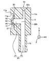
- FIG. 2 is a schematic sectional view taken along line II-II in FIG.
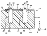
- FIG. 3 is a schematic cross-sectional view taken along line III-III in FIG.
- A) is a cross-sectional schematic diagram of the metal mold
- (b) is an enlarged view of the dashed-two dotted line part IVB in (a).
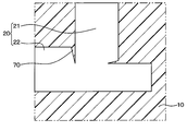
- FIG. 5 is an enlarged view of a case corresponding to a two-dot chain line portion V in FIG. 4 when the case is manufactured using the mold shown in FIG. 4.
- the pressure sensor of this embodiment is attached to the exhaust pipe in order to detect the pressure loss of a diesel particulate filter (DPF) provided in the exhaust pipe of a diesel engine, for example, and the upstream pressure of the DPF and the DPF It is used as a differential pressure detection type pressure sensor for detecting a differential pressure with respect to the downstream side pressure.
- DPF diesel particulate filter
- the pressure sensor of the present embodiment includes a case 10 formed by molding polyphenylene sulfide (PPS), polybutylene terephthalate (PBT), epoxy resin, or the like.
- PPS polyphenylene sulfide
- PBT polybutylene terephthalate
- epoxy resin epoxy resin
- the case 10 includes a substantially rectangular parallelepiped body 11 having a first surface 11a and another surface 11b, and first to fourth side surfaces 11c to 11f that connect the first surface 11a and other surface 11b, and a first side surface 11c.
- the two port portions 12 extending in the normal direction of the first side surface 11c, the connector portion 13 provided on the second side surface 11d, and the assembly portion 14 provided on the third side surface 11e.
- the case 10 has a pressure introduction hole 20 into which the measurement medium is introduced, as shown in FIGS.
- the pressure introducing hole 20 is configured by a first introducing hole 21 formed in the main body portion 11 and a second introducing hole 22 formed in the main body portion 11 and the port portion 12.
- the normal direction to the one surface 11a is the X direction
- the normal direction to the first side surface 11c is the Y direction
- the second side surface 11d is the fourth side surface 11f.
- a normal direction with respect to the Z direction will be described.
- the first introduction hole 21 is formed from the bottom surface of the recess 11g formed on the one surface 11a of the main body 11 toward the other surface 11b. In the present embodiment, the first introduction hole 21 extends in a direction parallel to the X direction.
- the second introduction hole 22 penetrates the port portion 12 and is also formed in the main body portion 11 along the extending direction (Y direction) of the port portion 12.
- the second introduction hole 22 has a communication portion 22b in which a portion between the opening portion on the distal end side in the projecting direction of the port portion 12 and the end portion on the opposite side to the opening portion communicates with the first introduction hole 21.
- the case 10 is formed with a pressure introduction hole 20 that penetrates the main body portion 11 and the port portion 12.
- the second introduction hole 22 is configured to have a space increasing chamber 22a in a portion opposite to the port portion 12 side from the communication portion 22b.
- This space increasing chamber 22a is not necessary for introducing the measurement medium, and the second introduction is provided between the opening on the distal end side in the protruding direction of the port portion 12 and the end opposite to the opening. This is to lengthen the hole 22.
- the angle ⁇ formed by the wall surface on the port portion 12 side of the wall surface constituting the first introduction hole 21 and the wall surface of the second introduction hole 22 connected to the wall surface is 90 °. That is, the pressure introducing hole 20 of the present embodiment is substantially T-shaped.
- the opening formed on the one surface 11 a corresponds to an opening on one end
- the opening on the distal end side in the protruding direction of the port portion 12 corresponds to the opening on the other end.
- the first introduction hole 21 and the second introduction hole 22 are formed so that axes passing through the center intersect.
- a sensor substrate 30 is mounted in a recess 11g formed in the main body 11 via an adhesive (not shown).
- the sensor substrate 30 is a printed circuit board or the like, on which a plurality of pads (not shown) are formed on the surface (one surface opposite to the case 10 side), and the sensor chip 40 and the circuit chip 43 are mounted. Further, two through holes 31 communicating with each pressure introducing hole 20 are formed.
- the sensor chip 40 is configured using a rectangular plate-shaped silicon substrate, and has a thin diaphragm 42 formed by forming a concave portion 41 on the back surface.
- the sensor chip 40 is illustrated to configure a bridge circuit on the diaphragm 42.
- the gauge resistance which does not do is formed. That is, in the sensor chip 40 of the present embodiment, when pressure is applied to the diaphragm 42, the resistance value of the gauge resistance changes, the voltage of the bridge circuit changes, and a semiconductor that outputs a sensor signal corresponding to the change in voltage. It is a diaphragm type.
- Each sensor chip 40 is mounted on the sensor substrate 30 with an adhesive (not shown) on the back side so as to close each through-hole 31 formed in the sensor substrate 30.
- an adhesive not shown
- the measurement medium introduced into the pressure introducing hole 20 from the opening on the distal end side in the protruding direction of the port portion 12 is applied to the sensor chip 40.
- the circuit chip 43 outputs a drive signal to each sensor chip 40 and outputs a detection signal to the outside, and also receives a sensor signal from the sensor chip 40 and amplifies and performs arithmetic processing on the sensor signal. And a control circuit for outputting to.
- the sensor substrate 30 is mounted on an area different from the sensor chip 40 via an adhesive (not shown).
- the pads formed on the sensor chip 40, the circuit chip 43, and the sensor substrate 30 are appropriately electrically connected via bonding wires (not shown) made of gold, aluminum, or the like.
- a gel-like protective member 50 is disposed in each through hole 31 of the sensor substrate 30 and the recess 41 of the sensor chip 40.
- the protective member 50 is for protecting the through hole 31 (sensor substrate 30) and the diaphragm 42 (sensor chip 40) from corrosive gas and humidity contained in the measurement medium. That is, in the present embodiment, the pressure of the measurement medium is applied to the diaphragm 42 via the protective member 50.
- the protective member 50 for example, fluorine gel, silicon gel, fluorosilicone gel or the like is used.
- fluorine gel for example, fluorine gel, silicon gel, fluorosilicone gel or the like is used.
- the condensed water due to the exhaust gas has strong acidity because nitrogen oxides and sulfur oxides contained in the exhaust gas are dissolved therein, so that the protective member 50 has high acid resistance. It is preferable to use a fluorine gel.
- the case 10 includes a plurality of metal terminals 15, and each terminal 15 is held in the case 10 by being integrally formed with the case 10 by insert molding. ing.
- each terminal 15 is held so as to penetrate the case 10, and one end portion protrudes into the recess 11 g and the other end portion protrudes into the connector portion 13.
- One end of each terminal 15 protruding into the recess 11g is electrically connected to the circuit chip 43 via a bonding wire (not shown).
- the connector part 13 is made into the cylindrical shape extended in the normal line direction (Y direction) of the 2nd side surface 11d, and the inside is made into the cavity part. For this reason, the other end part which protrudes in the connector part 13 among each terminal 15 is exposed in the connector part 13, and is electrically connected with an external wiring member etc. here.
- the fixing hole 14 a is configured by fitting a metal ring into the wall surface of a through hole formed in the resin constituting the assembly portion 14.
- the mold 60 includes a cavity formed by matching an upper mold 61 and a lower mold 62 that constitute an outer shape of the case 10, and the upper mold 61 and the lower mold 62.
- the first and second slide molds 64 and 65 are slidable (movable) in the interior 63.
- the first slide mold 64 slides in the upper mold 61 by the action of a pin (not shown) included in the mold 60, and forms the first introduction hole 21 when resin is injected into the cavity 63. It is.
- the second slide mold 65 slides between the upper mold 61 and the lower mold 62 by the action of a pin (not shown) included in the mold 60, and the second slide mold 65 is formed when resin is injected into the cavity 63.
- the introduction hole 22 is formed.
- the second slide mold 65 has a recess 65 a formed on the tip side opposite to the part sandwiched between the upper mold 61 and the lower mold 62 among the parts facing the upper mold 61. ing.
- the thickness of the second slide die 65 is made thinner than the portion sandwiched between the upper side 61 and the lower die 62.
- the upper die 61 is formed with a gate 66 as a supply passage for resin injected into the cavity 63.
- the lower mold 62 is formed with a knockout pin (not shown) for releasing the case 10 after the case 10 is molded.
- the case 10 is manufactured by injecting resin into such a mold 60 and curing it. Specifically, first, the terminal 15 is held between the upper die 61 and the lower die 62 and held in the cavity 63.
- the first slide mold 64 is slid to project the tip into the cavity 63
- the second slide mold 65 is slid to project the tip into the cavity 63.
- the tip of the second slide mold 65 opposite to the portion sandwiched between the upper mold 61 and the lower mold 62 is from the first slide mold 64.
- the front end surface of the first slide mold 64 is brought into close contact with the bottom and side surfaces of the recess 65 formed in the second slide mold 65 so as to protrude.
- the mold 60 is heated to a temperature suitable for the resin curing reaction, and a nozzle portion of an injection unit (not shown) is brought into contact with the upper side of the gate 66 to inject liquid resin from the gate 66 to the cavity. 63 is filled with resin. Thereby, the resin filled in the cavity 63 is cured and the case 10 is manufactured.
- burrs may occur at the close contact portion between the first slide mold 64 and the second slide mold 65.
- the first and second slide molds 64 and 65 are in close contact as described above. Therefore, as shown in FIG.
- the burr 70 formed between the wall surface and the wall surface of the second introduction hole 22 connected to the wall surface has a shape protruding into the second introduction hole 22.
- first and second slide molds 64 and 65 are slid and pulled out from the case 10. Then, the upper mold 61 and the lower mold 62 are separated from the case 10 using a knockout pin provided in the lower mold 62.
- a sensor substrate 30 having a through hole 31 is prepared, and a sensor chip 40 and a circuit chip 43 are mounted on the sensor substrate 30 so as to close the through hole 31.
- the sensor chip 40 and the circuit chip 43 are electrically connected via bonding wires, and the protective member 50 is disposed in the through hole 31 of the sensor substrate 30 and the recess 41 of the sensor chip 40.
- the pressure sensor is manufactured by mounting the sensor substrate 30 in the recess 11g formed in the case 10 and electrically connecting the terminal 15 and the circuit chip 43 via bonding wires.
- the second introduction hole 22 of the pressure introduction holes 20 is parallel to the top-and-bottom direction, and the opening on the distal end side in the protruding direction of the port portion 12 is the ground side.
- a bolt or the like is inserted into the exhaust pipe of the diesel engine as a member to be attached.
- the upstream exhaust of the DPF is introduced into one of the pressure introduction holes 20, and the downstream exhaust of the DPF is introduced into the other of the pressure introduction holes 20.
- the upstream pressure is detected by one sensor chip 40, and the downstream pressure is detected by the other sensor chip 40.
- the circuit chip 43 the difference between the upstream pressure and the downstream pressure is calculated, and the calculation result is output to the external circuit via the terminal 15. Thereby, the differential pressure of the exhaust pipe before and after the DPF is detected from the calculation result.
- the second introduction hole 22 of the pressure introduction hole 20 is parallel to the top-and-bottom direction, and the opening on the distal end side in the protruding direction of the port portion 12 is the ground side. It attaches to a to-be-attached member (for example, exhaust pipe of a diesel engine) so that it may become.
- the pressure introducing hole 20 has a space increasing chamber 22 a configured in a portion on the opposite side of the port portion 12 side from the portion communicating with the first introducing hole 21 in the second introducing hole 22.
- the space increasing chamber 22a increases the distance between the opening on the distal end side in the protruding direction of the port portion 12 and the end opposite to the opening, as compared with the conventional pressure sensor. For this reason, when a water drop is present in the second introduction hole 22 when a pressure pulsation occurs, the water drop is displaced in the second introduction hole 22. When reaching the opening on the leading end side in the direction, the inertial force applied to the water droplet increases. Therefore, water droplets can be easily discharged from the opening on the distal end side of the port portion 12 in the protruding direction from the conventional pressure sensor, and the drainage of the pressure introducing hole 20 can be improved.
- the first experiment results when the frequency of vibration applied in the vertical direction (Y direction) is 10 Hz.
- the second experiment is when the frequency of vibration applied in the vertical direction (Y direction) is 300 Hz.
- the third result is an experimental result in which the frequency of vibration applied in the vertical direction (Y direction) is 1000 Hz. Further, in the case without the space increasing chamber 22a, the liquid in the pressure introduction hole 20 was not drained even if the vibration was continuously applied for 600 seconds at the second time and the third time.
- the corners of the wall surfaces constituting the space increasing chamber 22a are rounded.
- the second introduction hole 22 has a shape in which a corner of the space increasing chamber 22a on the opposite side of the communication portion 22b is rounded and has a curvature.
- 7 is a schematic cross-sectional view corresponding to the line II-II in FIG.
- the contact area between the water droplet and the wall surface becomes small at the corner of the wall surface, and the surface tension generated thereby becomes small, the drainage can be further improved.
- FIG. 8 is a schematic cross-sectional view corresponding to the line III-III in FIG.
- the present disclosure can also be applied to a pressure sensor having the pressure introduction hole 20 in which the axis passing through the center of the first introduction hole 21 and the axis passing through the center of the second introduction hole 22 do not intersect.
- the wall on the opposite side to the wall surface located on the second introduction hole 22 side is inclined toward the second introduction hole 22 side. Yes. For this reason, when a pressure sensor is inclined and attached so that the one surface 11a becomes the top side in the top and bottom direction and the other surface 11b becomes the ground side, when water drops stay in the first introduction hole 21, It is possible to facilitate the flow into the second introduction hole 22.
- the distance from the axis L to the second introduction hole 22 in the Z direction is longer than the distance from the first introduction hole 21.
- the second introduction in the Z direction from the axis L is described.
- the distance to the hole 22 may be shorter than the distance to the first introduction hole 21.
- the first introduction hole 21 is inclined to the port portion 12 side (lower side in FIG. 9) with respect to the second introduction hole 22.
- the first introduction hole 21 extends toward the communication part 22 b so as to be inclined toward the port part 12 with respect to the second introduction hole 22.
- 9 is a schematic cross-sectional view corresponding to the line II-II in FIG.
- the fourth embodiment may be combined with the second and third embodiments, and the first introduction hole 21 may be inclined toward the port portion 12 toward the second introduction hole 22 side.
- the said 2nd Embodiment may be combined with the said 3rd Embodiment, and the corner
Landscapes
- Physics & Mathematics (AREA)
- General Physics & Mathematics (AREA)
- Measuring Fluid Pressure (AREA)
- Engineering & Computer Science (AREA)
- Manufacturing & Machinery (AREA)
- Mechanical Engineering (AREA)
Abstract
Description
第1実施形態について説明する。なお、本実施形態の圧力センサは、例えば、ディーゼルエンジンの排気管に設けられたディーゼルパティキュレートフィルタ(DPF)の圧力損失を検出するために当該排気管に取り付けられ、DPFの上流側圧力とDPFの下流側圧力との差圧を検出する差圧検出型の圧力センサとして用いられる。
第2実施形態について説明する。本実施形態は、第1実施形態に対して第2導入孔22の形状を変更したものであり、その他に関しては第1実施形態と同様であるため、ここでは説明を省略する。
第3実施形態について説明する。本実施形態は、第1実施形態に対して第1導入孔21の形状を変更したものであり、その他に関しては第1実施形態と同様であるため、ここでは説明を省略する。
第4実施形態について説明する。本実施形態は、第1実施形態に対して第1導入孔21の形状を変更したものであり、その他に関しては第1実施形態と同様であるため、ここでは説明を省略する。
上記各実施形態では、ケース10に圧力導入孔20が2つ形成されたものを説明したが、ケース10に形成される圧力導入孔20は1つのみであってもよい。
Claims (7)
- ケース(10)と、
測定媒体に応じたセンサ信号を出力するセンサチップ(40)と、を備え、
前記ケースには当該ケースを貫通し、前記測定媒体を導入する圧力導入孔(20)が形成され、前記圧力導入孔における一端の開口部を閉塞するように前記センサチップが搭載される圧力センサにおいて、
前記圧力導入孔は、
前記一端の開口部を構成すると共に所定方向に延設された第1導入孔(21)と、
前記一端の開口部と反対側に位置する他端の開口部を構成すると共に前記所定方向と異なる方向に延設され、前記第1導入孔と連通される第2導入孔(22)と、を含み、
前記第1導入孔を構成する壁面のうち前記他端の開口部側の壁面と、当該壁面と繋がっている前記第2導入孔の壁面との成す角度(θ)が90°以上とされ、
前記第2導入孔は、
前記他端の開口部と、前記他端の開口部と反対側の端部との間で前記第1導入孔と連通する連通部(22b)と、
前記他端の開口部から離れるように前記連通部からさらに伸びる空間増加室(22a)とを有する圧力センサ。 - 前記第2導入孔は、前記連通部とは反対側の前記空間増加室の角部が丸められている請求項1に記載の圧力センサ。
- 前記第1導入孔の中心を通り、前記第1導入孔の延設方向に延びる軸と、前記第2導入孔の中心を通り、前記第2導入孔の延設方向に延びる軸とが交差せず、
前記第1導入孔を構成する壁面における前記第2導入孔側と反対側に位置する壁面は、前記一端の開口部と反対側の部分が前記第2導入孔側に傾斜している傾斜部(21a)を有する請求項1または2に記載の圧力センサ。 - 前記第1導入孔は、前記一端の開口部側から前記第2導入孔の連通部に向かって前記他端の開口部側に傾斜している請求項1ないし3のいずれか1つに記載の圧力センサ。
- 前記ケースには、2つの前記圧力導入孔が形成されており、
2つの前記圧力導入孔には、異なる測定媒体が導入される請求項1ないし4のいずれか1つに記載の圧力センサ。 - 請求項1ないし5のいずれか1つに記載の圧力センサの製造方法であって、
合致させることで内部にキャビティ(63)を構成する上型(61)および下型(62)と、前記キャビティ内をスライド可能であって前記第1導入孔を形成するための第1スライド型(64)と、前記キャビティ内をスライド可能であって前記第2導入孔を形成するための第2スライド型(65)と、を備える型(60)を用意する工程と、
前記キャビティ内において、前記第2スライド型のうち前記キャビティ内に突出している先端と当該先端の反対側の部分との間に前記第1スライド型のうち前記キャビティ内に突出している先端を密着させる工程と、
前記キャビティ内に前記樹脂を注入し、前記第1スライド型にて前記第1導入孔が形成され、前記第2スライド型にて前記第2導入孔が形成された前記ケースを形成する工程と、
前記圧力導入孔における前記一端の開口部を閉塞するように前記センサチップを前記ケースに搭載する工程と、を有する圧力センサの製造方法。 - 前記型を用意する工程では、前記第2スライド型として、前記キャビティ内に突出している先端側に凹部が形成されたものを用意し、
前記密着させる工程では、前記第1スライド型のうち前記キャビティ内に突出している先端を前記凹部の底面および側面に密着させる請求項6に記載の圧力センサの製造方法。
Priority Applications (2)
| Application Number | Priority Date | Filing Date | Title |
|---|---|---|---|
| DE112013006062.0T DE112013006062B4 (de) | 2012-12-18 | 2013-12-12 | Drucksensor und Verfahren zu dessen Fertigung |
| US14/436,957 US9588000B2 (en) | 2012-12-18 | 2013-12-12 | Pressure sensor and method for manufacturing same |
Applications Claiming Priority (2)
| Application Number | Priority Date | Filing Date | Title |
|---|---|---|---|
| JP2012-276032 | 2012-12-18 | ||
| JP2012276032A JP6079206B2 (ja) | 2012-12-18 | 2012-12-18 | 圧力センサ |
Publications (1)
| Publication Number | Publication Date |
|---|---|
| WO2014097585A1 true WO2014097585A1 (ja) | 2014-06-26 |
Family
ID=50977948
Family Applications (1)
| Application Number | Title | Priority Date | Filing Date |
|---|---|---|---|
| PCT/JP2013/007303 Ceased WO2014097585A1 (ja) | 2012-12-18 | 2013-12-12 | 圧力センサとその製造方法 |
Country Status (4)
| Country | Link |
|---|---|
| US (1) | US9588000B2 (ja) |
| JP (1) | JP6079206B2 (ja) |
| DE (1) | DE112013006062B4 (ja) |
| WO (1) | WO2014097585A1 (ja) |
Cited By (1)
| Publication number | Priority date | Publication date | Assignee | Title |
|---|---|---|---|---|
| CN110955946A (zh) * | 2019-10-29 | 2020-04-03 | 中国铁建电气化局集团第五工程有限公司 | 一种机房布线优化方法及系统 |
Families Citing this family (5)
| Publication number | Priority date | Publication date | Assignee | Title |
|---|---|---|---|---|
| DE102014209874A1 (de) * | 2014-05-23 | 2015-11-26 | Conti Temic Microelectronic Gmbh | Steuergerät für ein Fahrzeug mit einem einen Drucksensor aufweisenden Gehäuse |
| JP6387912B2 (ja) * | 2015-07-06 | 2018-09-12 | 株式会社デンソー | 圧力センサ |
| DE102015121401A1 (de) * | 2015-12-09 | 2017-06-14 | ETO SENSORIC GmbH | Drucksensorvorrichtung |
| MX2018010577A (es) * | 2016-03-04 | 2018-12-19 | Imflux Inc | Kit de sensor externo para aparato de moldeo por inyeccion y metodos de uso. |
| EP3276242B1 (en) * | 2016-07-28 | 2019-08-28 | Sensirion AG | Differential pressure sensor comprising an adaptor device |
Citations (6)
| Publication number | Priority date | Publication date | Assignee | Title |
|---|---|---|---|---|
| JPS57138037U (ja) * | 1981-02-23 | 1982-08-28 | ||
| JPS5866034A (ja) * | 1981-10-14 | 1983-04-20 | Nippon Denso Co Ltd | 圧力検出装置 |
| JPS61143040U (ja) * | 1985-02-25 | 1986-09-04 | ||
| JPH03200035A (ja) * | 1989-12-28 | 1991-09-02 | Matsushita Electric Ind Co Ltd | 半導体圧力センサ |
| JPH1114486A (ja) * | 1997-06-25 | 1999-01-22 | Matsushita Electric Works Ltd | 圧力センサ |
| WO2005116429A1 (ja) * | 2004-05-26 | 2005-12-08 | Mikuni Corporation | スロットルシステムおよびセンサユニット |
Family Cites Families (5)
| Publication number | Priority date | Publication date | Assignee | Title |
|---|---|---|---|---|
| JP4375460B2 (ja) * | 2007-08-08 | 2009-12-02 | 株式会社デンソー | 圧力センサ |
| JP2010256186A (ja) * | 2009-04-24 | 2010-11-11 | Panasonic Electric Works Co Ltd | 圧力センサ |
| JP2013003112A (ja) | 2011-06-21 | 2013-01-07 | Denso Corp | 構造体 |
| US9310267B2 (en) * | 2014-02-28 | 2016-04-12 | Measurement Specialities, Inc. | Differential pressure sensor |
| US9593995B2 (en) * | 2014-02-28 | 2017-03-14 | Measurement Specialties, Inc. | Package for a differential pressure sensing die |
-
2012
- 2012-12-18 JP JP2012276032A patent/JP6079206B2/ja active Active
-
2013
- 2013-12-12 WO PCT/JP2013/007303 patent/WO2014097585A1/ja not_active Ceased
- 2013-12-12 US US14/436,957 patent/US9588000B2/en active Active
- 2013-12-12 DE DE112013006062.0T patent/DE112013006062B4/de active Active
Patent Citations (6)
| Publication number | Priority date | Publication date | Assignee | Title |
|---|---|---|---|---|
| JPS57138037U (ja) * | 1981-02-23 | 1982-08-28 | ||
| JPS5866034A (ja) * | 1981-10-14 | 1983-04-20 | Nippon Denso Co Ltd | 圧力検出装置 |
| JPS61143040U (ja) * | 1985-02-25 | 1986-09-04 | ||
| JPH03200035A (ja) * | 1989-12-28 | 1991-09-02 | Matsushita Electric Ind Co Ltd | 半導体圧力センサ |
| JPH1114486A (ja) * | 1997-06-25 | 1999-01-22 | Matsushita Electric Works Ltd | 圧力センサ |
| WO2005116429A1 (ja) * | 2004-05-26 | 2005-12-08 | Mikuni Corporation | スロットルシステムおよびセンサユニット |
Cited By (1)
| Publication number | Priority date | Publication date | Assignee | Title |
|---|---|---|---|---|
| CN110955946A (zh) * | 2019-10-29 | 2020-04-03 | 中国铁建电气化局集团第五工程有限公司 | 一种机房布线优化方法及系统 |
Also Published As
| Publication number | Publication date |
|---|---|
| DE112013006062B4 (de) | 2020-09-03 |
| DE112013006062T5 (de) | 2015-08-27 |
| JP2014119391A (ja) | 2014-06-30 |
| US20150247772A1 (en) | 2015-09-03 |
| US9588000B2 (en) | 2017-03-07 |
| JP6079206B2 (ja) | 2017-02-15 |
Similar Documents
| Publication | Publication Date | Title |
|---|---|---|
| JP6079206B2 (ja) | 圧力センサ | |
| US10012522B2 (en) | Thermal flow meter | |
| JP5279667B2 (ja) | 熱式空気流量センサ | |
| US7603908B2 (en) | Semiconductor pressure sensor, manufacturing method thereof, and die for molding semiconductor pressure sensor | |
| US8733175B2 (en) | Pressure sensor | |
| JP4320963B2 (ja) | 圧力センサ | |
| KR20120053022A (ko) | 유량 센서 및 그 제조 방법 그리고 유량 센서 모듈 및 그 제조 방법 | |
| US10876872B2 (en) | Physical quantity detection device | |
| JPWO2019049513A1 (ja) | 熱式流量計 | |
| US9945706B2 (en) | Thermal-type air flow meter | |
| KR100697404B1 (ko) | 물리량 검출 장치 및 물리량 검출 수단 저장 케이스 | |
| US10260921B2 (en) | Thermal flow meter | |
| CN103764978A (zh) | 空气物理量检测装置 | |
| US20180188084A1 (en) | Physical Quantity Detection Device | |
| JP6520636B2 (ja) | 物理量センササブアセンブリおよび物理量測定装置 | |
| US10591331B2 (en) | Intake temperature detection device and maximum heat generating amount components mounted on a single circuit board | |
| JP6387912B2 (ja) | 圧力センサ | |
| CN104458112B (zh) | 压力检测装置及使用该压力检测装置的进气压力测定装置 | |
| CN108139249A (zh) | 物理量检测装置 | |
| US20200399118A1 (en) | Electronic device | |
| CN220794505U (zh) | 传感器 | |
| JP2022158414A (ja) | 物理量計測装置 | |
| US9804049B2 (en) | Pressure detection device and intake pressure measurement apparatus using the same | |
| WO2014136336A1 (ja) | センサ装置 | |
| KR102263026B1 (ko) | 압력센서 및 이의 제조방법 |
Legal Events
| Date | Code | Title | Description |
|---|---|---|---|
| 121 | Ep: the epo has been informed by wipo that ep was designated in this application |
Ref document number: 13865401 Country of ref document: EP Kind code of ref document: A1 |
|
| WWE | Wipo information: entry into national phase |
Ref document number: 14436957 Country of ref document: US |
|
| WWE | Wipo information: entry into national phase |
Ref document number: 112013006062 Country of ref document: DE Ref document number: 1120130060620 Country of ref document: DE |
|
| 122 | Ep: pct application non-entry in european phase |
Ref document number: 13865401 Country of ref document: EP Kind code of ref document: A1 |