EP3276242B1 - Differential pressure sensor comprising an adaptor device - Google Patents
Differential pressure sensor comprising an adaptor device Download PDFInfo
- Publication number
- EP3276242B1 EP3276242B1 EP16181714.3A EP16181714A EP3276242B1 EP 3276242 B1 EP3276242 B1 EP 3276242B1 EP 16181714 A EP16181714 A EP 16181714A EP 3276242 B1 EP3276242 B1 EP 3276242B1
- Authority
- EP
- European Patent Office
- Prior art keywords
- pressure sensor
- differential pressure
- axes
- face
- receptions
- Prior art date
- Legal status (The legal status is an assumption and is not a legal conclusion. Google has not performed a legal analysis and makes no representation as to the accuracy of the status listed.)
- Active
Links
- 210000002445 nipple Anatomy 0.000 claims description 74
- 230000008878 coupling Effects 0.000 claims description 43
- 238000010168 coupling process Methods 0.000 claims description 43
- 238000005859 coupling reaction Methods 0.000 claims description 43
- 238000007789 sealing Methods 0.000 claims description 16
- 210000002105 tongue Anatomy 0.000 claims description 11
- 239000012530 fluid Substances 0.000 claims description 6
- 210000000887 face Anatomy 0.000 description 12
- 239000000463 material Substances 0.000 description 5
- 210000001331 nose Anatomy 0.000 description 5
- 229920001971 elastomer Polymers 0.000 description 2
- 230000014759 maintenance of location Effects 0.000 description 2
- 229920001296 polysiloxane Polymers 0.000 description 2
- 239000013013 elastic material Substances 0.000 description 1
- 239000003292 glue Substances 0.000 description 1
- 239000004033 plastic Substances 0.000 description 1
- 229920003023 plastic Polymers 0.000 description 1
- 230000002035 prolonged effect Effects 0.000 description 1
- 238000005476 soldering Methods 0.000 description 1
- 239000002699 waste material Substances 0.000 description 1
- XLYOFNOQVPJJNP-UHFFFAOYSA-N water Substances O XLYOFNOQVPJJNP-UHFFFAOYSA-N 0.000 description 1
Images
Classifications
-
- F—MECHANICAL ENGINEERING; LIGHTING; HEATING; WEAPONS; BLASTING
- F16—ENGINEERING ELEMENTS AND UNITS; GENERAL MEASURES FOR PRODUCING AND MAINTAINING EFFECTIVE FUNCTIONING OF MACHINES OR INSTALLATIONS; THERMAL INSULATION IN GENERAL
- F16L—PIPES; JOINTS OR FITTINGS FOR PIPES; SUPPORTS FOR PIPES, CABLES OR PROTECTIVE TUBING; MEANS FOR THERMAL INSULATION IN GENERAL
- F16L39/00—Joints or fittings for double-walled or multi-channel pipes or pipe assemblies
- F16L39/02—Joints or fittings for double-walled or multi-channel pipes or pipe assemblies for hoses
-
- F—MECHANICAL ENGINEERING; LIGHTING; HEATING; WEAPONS; BLASTING
- F16—ENGINEERING ELEMENTS AND UNITS; GENERAL MEASURES FOR PRODUCING AND MAINTAINING EFFECTIVE FUNCTIONING OF MACHINES OR INSTALLATIONS; THERMAL INSULATION IN GENERAL
- F16L—PIPES; JOINTS OR FITTINGS FOR PIPES; SUPPORTS FOR PIPES, CABLES OR PROTECTIVE TUBING; MEANS FOR THERMAL INSULATION IN GENERAL
- F16L33/00—Arrangements for connecting hoses to rigid members; Rigid hose connectors, i.e. single members engaging both hoses
- F16L33/30—Arrangements for connecting hoses to rigid members; Rigid hose connectors, i.e. single members engaging both hoses comprising parts inside the hoses only
-
- F—MECHANICAL ENGINEERING; LIGHTING; HEATING; WEAPONS; BLASTING
- F16—ENGINEERING ELEMENTS AND UNITS; GENERAL MEASURES FOR PRODUCING AND MAINTAINING EFFECTIVE FUNCTIONING OF MACHINES OR INSTALLATIONS; THERMAL INSULATION IN GENERAL
- F16L—PIPES; JOINTS OR FITTINGS FOR PIPES; SUPPORTS FOR PIPES, CABLES OR PROTECTIVE TUBING; MEANS FOR THERMAL INSULATION IN GENERAL
- F16L41/00—Branching pipes; Joining pipes to walls
- F16L41/008—Branching pipes; Joining pipes to walls for connecting a measuring instrument
-
- F—MECHANICAL ENGINEERING; LIGHTING; HEATING; WEAPONS; BLASTING
- F16—ENGINEERING ELEMENTS AND UNITS; GENERAL MEASURES FOR PRODUCING AND MAINTAINING EFFECTIVE FUNCTIONING OF MACHINES OR INSTALLATIONS; THERMAL INSULATION IN GENERAL
- F16L—PIPES; JOINTS OR FITTINGS FOR PIPES; SUPPORTS FOR PIPES, CABLES OR PROTECTIVE TUBING; MEANS FOR THERMAL INSULATION IN GENERAL
- F16L41/00—Branching pipes; Joining pipes to walls
- F16L41/02—Branch units, e.g. made in one piece, welded, riveted
- F16L41/03—Branch units, e.g. made in one piece, welded, riveted comprising junction pieces for four or more pipe members
-
- G—PHYSICS
- G01—MEASURING; TESTING
- G01L—MEASURING FORCE, STRESS, TORQUE, WORK, MECHANICAL POWER, MECHANICAL EFFICIENCY, OR FLUID PRESSURE
- G01L13/00—Devices or apparatus for measuring differences of two or more fluid pressure values
-
- G—PHYSICS
- G01—MEASURING; TESTING
- G01L—MEASURING FORCE, STRESS, TORQUE, WORK, MECHANICAL POWER, MECHANICAL EFFICIENCY, OR FLUID PRESSURE
- G01L19/00—Details of, or accessories for, apparatus for measuring steady or quasi-steady pressure of a fluent medium insofar as such details or accessories are not special to particular types of pressure gauges
- G01L19/0007—Fluidic connecting means
- G01L19/003—Fluidic connecting means using a detachable interface or adapter between the process medium and the pressure gauge
-
- G—PHYSICS
- G01—MEASURING; TESTING
- G01L—MEASURING FORCE, STRESS, TORQUE, WORK, MECHANICAL POWER, MECHANICAL EFFICIENCY, OR FLUID PRESSURE
- G01L19/00—Details of, or accessories for, apparatus for measuring steady or quasi-steady pressure of a fluent medium insofar as such details or accessories are not special to particular types of pressure gauges
- G01L19/0007—Fluidic connecting means
- G01L19/0038—Fluidic connecting means being part of the housing
-
- F—MECHANICAL ENGINEERING; LIGHTING; HEATING; WEAPONS; BLASTING
- F16—ENGINEERING ELEMENTS AND UNITS; GENERAL MEASURES FOR PRODUCING AND MAINTAINING EFFECTIVE FUNCTIONING OF MACHINES OR INSTALLATIONS; THERMAL INSULATION IN GENERAL
- F16L—PIPES; JOINTS OR FITTINGS FOR PIPES; SUPPORTS FOR PIPES, CABLES OR PROTECTIVE TUBING; MEANS FOR THERMAL INSULATION IN GENERAL
- F16L25/00—Constructive types of pipe joints not provided for in groups F16L13/00 - F16L23/00 ; Details of pipe joints not otherwise provided for, e.g. electrically conducting or insulating means
- F16L25/14—Joints for pipes of different diameters or cross-section
-
- G—PHYSICS
- G01—MEASURING; TESTING
- G01D—MEASURING NOT SPECIALLY ADAPTED FOR A SPECIFIC VARIABLE; ARRANGEMENTS FOR MEASURING TWO OR MORE VARIABLES NOT COVERED IN A SINGLE OTHER SUBCLASS; TARIFF METERING APPARATUS; MEASURING OR TESTING NOT OTHERWISE PROVIDED FOR
- G01D11/00—Component parts of measuring arrangements not specially adapted for a specific variable
- G01D11/30—Supports specially adapted for an instrument; Supports specially adapted for a set of instruments
Definitions
- the present invention relates to a differential pressure sensor that comprises an adaptor device for establishing a connection between a further device with hose connectors and at least one hose, the further device being a differential pressure sensor package of the differential pressure sensor.
- Some differential pressure sensor devices have two or more coupling nozzles for connecting proximal ends of hoses for the purpose of creating an exclusive fluid communication between the coupling nozzles and distal hose ends.
- US 2009/0194831 A1 discloses a differential pressure sensor device with two coupling nozzles, wherein a housing is configured to directly connect to a printed circuit board assembly and a pressure die is mounted on the printed circuit board assembly.
- the hoses - e . g . hoses from silicone or rubber - are often consumer goods and have a predetermined cross-section and material thickness. Hose material and material thickness may generally be optimized to the specific purpose of the device they are connected to. It may also be that a specific hose type shall be used as it is easily available.
- the hose thickness has, however, to fulfill the following requirement: It shall be less than half of the distance between the two neighboring coupling nozzles to be connected; else the hoses do not fit both on the same device at the same time. Accordingly, either a specific device geometry is necessary for a given hose type or a specific hose type is necessary for a given device geometry.
- US 2013/0319556 A1 discloses inter alia, a bypass manifold for a water treatment system.
- the bypass manifold may have inlets and outlets that are differently spaced.
- US 2015/0145240 A1 discloses, inter alia, a thermal relief valve assembly having two inlet ports and two outlet ports, the inlet ports and outlet ports being differently spaced.
- DE 40 32 562 A1 discloses a distribution arrangement for distributing fluid media.
- EP 1 451 417 B1 discloses a waste removal system with different outlet nozzle arrangements.
- WO 2016/090493 A1 discloses a flow splitter comprising a plurality of passages through a one-piece body.
- the present invention provides a differential pressure sensor comprising a differential pressure sensor package comprising a first hose coupling nozzle and a second hose coupling nozzle, the differential pressure sensor further comprising an adaptor device comprising a base body.
- the base body itself provides a first reception for receiving the first hose coupling nozzle and a second reception for receiving the second hose coupling nozzle.
- the first and second receptions are spaced apart from one another by a first distance.
- the adaptor device further comprises a first connecting nipple for receiving a first hose, i.e. a hose portion may be pushed thereon.
- the first connecting nipple has, at its distal end (i.e. away from the base body), a first muzzle opening.
- the first connecting nipple is attached to the base body and connected to the first reception by a first passage such as to establish a continuous channel from the respective reception to the respective muzzle opening.
- the adaptor device further comprises a second connecting nipple for receiving a second hose.
- the second connecting nipple has, at its distal end, a second muzzle opening and is attached to the base body and connected to the second reception by a second passage.
- the first and second passages are continuous and fluidly connect the first and second muzzle openings to the first and second receptions, respectively. Moreover, the first and second muzzle openings are spaced apart at a second distance.
- the adaptor device is configured to be connected to the differential pressure sensor package, in particular to a (printed) circuit board of the differential pressure sensor package,
- the adaptor device can be actually attached to the differential pressure sensor package.
- the coupling nozzles can be the pneumatic connectors of the differential pressure sensor package.
- the differential pressure sensor package will also be referred to as the "further device”.
- the adaptor device is configured to receive, upon connection with the further device, the first and second hose coupling nozzles in the first and second receptions, respectively, preferably in a fluid-tight manner.
- the second distance now longer than the first distance.
- the second distance is at least 30% longer, more preferably at least 50% longer, more preferably at least 100% or at least 200% longer, most preferably at least 5-times to 7-times longer than the first distance.
- the first distance is smaller than 15 millimeters, preferably smaller than 10 millimeters, most preferably less than or equal to 5 millimeters.
- the term "adaptor device” refers to a coupling structure - preferably a single-piece unit, e.g. a molded piece - that may be arranged over the further device, whilst receiving the first and second coupling nozzle in the first and second receptions, respectively, such that the fluid outlet of the coupling nozzles is connected to the muzzle openings of the connecting nipples.
- the adaptor device is an extension structure that enlarges the distance of the ports to be connected to a hose such that thicker hoses or hoses with thicker material may be used.
- an exterior diameter of the connecting nipple may also be change, e.g. increased such that hoses with thicker inner diameters may be used.
- base body refers to the frame structure that accommodates the receptions and the connecting nipples and allows for connecting the adaptor device to the further device in a direct or indirect manner.
- the term "reception” refers to a receiving structure that is configured to receive the coupling nozzle and preferably allows for a substantially fluid-tight connection between coupling nozzle and the respective first or second passage.
- the receptions are cavities that are at least partly or completely circumferentially limited by wall structures, the wall structures providing lateral abutment to the received coupling nozzle such that as to stabilize the coupling nozzle in the reception. Sealing elements may be used to tighten the connection.
- the terms “coupling nozzle” and “connecting nipple” refer each to a connector part for receiving a terminal open portion of a hose, the hose being preferably flexible, e.g. made from silicone, rubber, or plastics.
- further device refers to a differential pressure sensor package that comprises coupling nozzles that shall be connected to hose-like structures for probing distant fluid conditions.
- the coupling nozzles can be two pneumatic ports.
- the present invention is based on the insight that an adaptor device may be used to increase the distance between the coupling nozzles of a complete sensor package by providing receptions for the coupling nozzles and connecting nipples that are, at least a their muzzle openings, further apart further apart from one another than the coupling nozzles are.
- the basic body may have any shape such as a circular or round disc shape or it may be a convex polytope.
- the basic body has a part or complete cuboidal shape with cuboid faces.
- the first and second connecting nipples are arranged on the same first cuboid face of the cuboid faces, wherein the first and second receptions are arranged on the same second cuboid face of the cuboid faces, the first cuboid face being different from the second cuboid face.
- the receptions may be arranged on a bottom face while the connecting nipples may be arranged on a lateral face or on the top face of the base body.
- the first and second connecting nipples have first and second longitudinal nipple axes, respectively, wherein the first and second longitudinal nipple axes are straight and extend in an inclined manner with respect to one another.
- the first and second longitudinal nipple axes form a V shape extending from the base body.
- the V shape may have an opening angle that ranges from 10 degrees to 165 degrees, preferably, said opening angle ranges between 45 degrees and 120 degrees, more preferably between 60 degrees and 100 degrees, e.g.: 60 degrees or 90 degrees.
- the opening angle depends on the target second distance which, in turn, depends on the length of the first and second connecting nipples.
- the V shape may preferably be symmetrical with respect to the front-back axis of the basic body (see below). It may, however, also be asymmetric, i.e. one arm of the V shape may be further bent outwardly than the other. Accordingly, it is also contemplated that one connecting nipple extends normally, i.e. perpendicularly, or in plane, i.e . parallel, from the face it is attached to, while the other connecting nipple is inclined to said face and the one connecting nipple.
- lengths of the first and second connecting nipples may be the same or may be different from one another, e.g. by at least 5%, 10%, 50%, or 100%.
- a diameter of the first and second connecting nipples may be the same or may be different, e.g. by at least 5%, 10%, 50%, or 100%.
- the geometry may depend on the specific design of the further device and/or on the purpose of the latter and on the hoses to be used.
- first and second connecting nipples are not or not entirely straight but are bent and/or have steps along their longitudinal extension. Accordingly, the connecting nipples may have any form between the receptions and the muzzle openings.
- the first and second receptions have, on their depth or on a step along the extension, a sealing element for forming the fluid-tight connection with the first and second hose coupling nozzles.
- This sealing element may be a sealing ring or piece that may be made from an elastic material and matches the shape of the cross-section of the coupling nozzle.
- the first and second receptions have first and second longitudinal reception axes, respectively, wherein the first and second longitudinal reception axes extend parallel to on another.
- the first and second longitudinal reception axes are straight for receiving straight coupling nozzles.
- the cross-sectional shape of the receptions may be similar as the cross-sectional shape of the coupling nozzle to be received.
- the cross-sectional shapes of the receptions as well as of the connecting nipples are round, e.g. they have the shape of a straight or at least partly bent cylinder.
- first and second longitudinal reception axes span a second plane.
- the second plane may extend parallel to one of the cuboid faces of the basic body.
- the first and second longitudinal nipple axes span a first plane, wherein the first plane and the second plane intersect one another, wherein an intersection angle between the first plane and the second plane preferably ranges between 45 degrees to 165 degrees; wherein an intersecting line of the first plane and the second plane extends preferably parallel to a connection line of the first and second muzzle openings of the connecting nipples, or parallel the second cuboid face and/or wherein the intersection angle is preferably 120 degrees or smaller, e.g. 90 degrees.
- the first and second connecting nipples are provided with an abutment, the abutment having at least one proximal face facing the tip of the connecting nipple and at least one distal face facing the other way.
- the first and second longitudinal nipple axes preferably intersect with the at least one proximal and distal faces.
- the abutment provides a stop for a hose that is pushed partially over the connecting nipple.
- the abutment is elongated in a direction of the second distance, i.e. along the connecting line of the first and second muzzle openings.
- the elongation minimizes a height of the adaptor device whilst ensuring a secure stop surface in the elongation direction.
- the abutment may be at least one or several plate-like elements.
- the abutment comprises at least two abutment rings, wherein on each of the first and second connecting nipples is arranged at least one abutment ring.
- the abutment ring then at least partially or completely circumferentially surrounds the connecting nipple.
- the outer shape of the abutment rings may be at least in part or completely round, preferably circular or elliptical, or have a polygonal shape.
- the proximal and distal faces of the abutment extend parallel to one of the cuboid faces of the basic body.
- the distal and/or proximal faces of the abutment extend perpendicularly to the longitudinal extension of the connecting nipple.
- the proximal face may be arranged at a distance to the one of the cuboid faces.
- a gap is formed between said cuboid face and the proximal face of the abutment, the gap being adapted for receiving portions of a further wall structure.
- the further wall structure may be the housing of a larger device containing the second device.
- the connecting nipples extend through the further wall structure, and may be engaged from the outside while the adapter device and the further wall structure are engaged in at least a partial positive locking manner, preferably also in an additional force fit.
- the base body has a cavity and the first and second receptions are arranged in said cavity.
- a reception structure is additionally arranged in the cavity such as to at least partially surround the first and second receptions.
- the reception structure preferably delimits a sub-cavity within the cavity, the sub-cavity being shaped for receiving the further device, e.g ., the differential pressure sensor package with the first and second coupling nozzles, or parts thereof.
- the sub-cavity may have a substantially cuboidal shape.
- the adapter device further comprises at least one first fastening structure for connecting the adaptor device to the further device, in particular to a circuit board of the further device.
- these fastening structures are quick-release coupling elements for easy and quick connection of the adaptor device with the further device, the latter carrying the second fastening structure.
- the at least one first fastening structure comprises at least one, preferably a plurality of snap-in tongues with a snap-in nose and/or at least one a through-hole through the basic body for connecting the adaptor device to the further device by means of bolts such as screws or the like. Soldering connections may also be provided through the through-hole.
- the first fastening structure may, for example, be selected from the group comprising: glue surfaces, bolt connections, screw connections, and hook connections of any kind.
- the first and second connecting nipples each comprise an attachment portion, the attachment portion being a pipe portion extending along the first and second nipple axes, respectively, and being attached to the first cuboid face of the base body.
- the first and second nipple axes extend preferably parallel to the first cuboid face.
- the free tip portions of the connecting nipples may be provided with a retention structure for securely engaging the hose portion.
- the retention structure may comprise, e.g. , at least one rim, ring, or rib, extending at least partially circumferentially around the connecting nipple and extending in radial direction.
- the adaptor device is a single-piece element, preferably a molded piece. Any or some of the edges of the adaptor device may rounded such as to avoid damage to the hose.
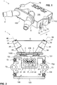
- Figures 1 to 3 show a first embodiment of the adaptor device 1 according to invention in a perspective top front view, a bottom view, and a perspective top rear view, respectively.
- the adaptor device 1 features a basic body 10 with a cuboidal shape and is sized in the cm range, e.g. : 6 cm x 7 cm x 1 cm.
- the base body 10 includes a top wall with a top face 100, a front wall with a front face 101, two side walls with lateral side faces 102, 104, and a rear wall with a rear face 103. There is no extra bottom wall such that the bottom face 105 is actually the bottom face of the top wall.
- the box-like base body 10 delimits a substantially cuboidal bottom cavity 106 which is open toward the bottom ( cf. Fig. 2 ).
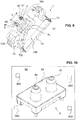
- the basic body 10 further comprises first and second receptions 2, 3 for receiving first and second coupling nozzles 81, 82 of a differential pressure sensor package 8 ( cf. Fig. 10 ), first and second connecting nipples 4, 5 for establishing a connection with flexible hoses (not shown), and a first fastening structure 7 for connection with a printed circuit board 84 ( cf. Fig. 10 ) on which the package 8 is arranged on.
- the first and second connecting nipples 4, 5 are single-piece elements that comprise attachment portions 41, 51, first and second intermediate portions 42, 44 and 52, 54 with an abutment 438 arranged therebetween, sealing rings 45, 55, and tip portions 46, 56, respectively.
- the first and second connecting nipples 4, 5 are mirror images from one another with respect to a mirror plane extending perpendicularly to the second plane P 2 (see below) and at the same time being the bisector plane of the V shape (see below).
- the tip portions 46, 56 have rounded distal edges 461, 561 that define muzzle openings 47, 57 of the first and second connecting nipple 4, 5, respectively.
- the tip portions 46, 56 are designed as straight pipe portions with proximal ends 460, 560.
- Proximal of the proximal ends 460, 560 of the tip portions 46, 56 extend the sealing rings 45, 55.
- the sealing rings 45, 55 are frustroconically shaped and taper in the distal direction.
- proximally facing stop surfaces 450, 550 are arranged. Accordingly, the first and second connecting nipples 4, 5 taper at the stop faces 450, 550 in a step-wise manner in the proximal direction. This ensures proper engagement of the adaptor device 1 and the connected hoses.
- first and second intermediate portions 42, 44 and 52, 54 extend proximal of the stop faces 450, 550.
- the first and second intermediate portions 42, 44 and 52, 54 have the same diameter as the tip portions 46, 56.
- the attachment sections 41, 51 are straight pipe portions as well that are attached over their length to the top face 101, whereby the first and second connecting nipples 4, 5 are attached to the base body 10.
- the first and second connecting nipples 4, 5 have each a longitudinal nipple axis, the first and second longitudinal nipple axes 48, 58, respectively ( cf. Fig. 2 ).
- the first and second longitudinal nipple axes 48, 58 form a V shape with an opening angle from 50 degrees to 70 degrees, e.g. 60 degrees.
- the first and second longitudinal axes 48, 58 span a first plane P 1 that extends parallel and at distance to the top face 100.
- the first and second connecting nipples 4, 5 have identical lengths (about the same as the first distance D or somewhat less) and also identical cross-sections.
- the first and second muzzle openings 47, 57 are spaced apart from one another by a second distance D.
- the first and second attachment portions 41, 51 receive at their proximal ends the first and second receptions 2, 3, respectively.
- the first distance d between the first and second receptions 2, 3 are shown in Fig. 2 (and Fig. 4 for the second embodiment, see below).
- the first distance d is about 6-times smaller than the second distance D.
- the second distance D may be 3 centimeters to 6 centimeters.
- the single abutment plate 438 is arranged between the first and second intermediate portions 42, 44 and 52, 54, respectively, connecting the first and second connecting nipples 4, 5 to one another.
- the abutment plate 438 extends parallel to the front face 101.
- the longitudinal nipple axes 48, 58 intersect the abutment plate 438 and extend angular to the plane defined by the abutment plate 438.
- the abutment plate 438 is an elongated shield with rounded short edges that acts as a stop for hose parts pushed over the sealing rings 45, 55.
- a distal face 431 is provided on the abutment plate 438. As can be seen from the Figures, the distal face 431 extends parallel to the front face 101 of the base body 10.
- a gap 1000 is created between a proximal face 430 of the abutment plate 438 and the front face 101 of the base body 10.
- This gap 1000 may be used for receiving a wall structure of, for example, a housing of the unit comprising the adaptor device 1 and the differential pressure sensor package 8 on the printed circuit board to which the package 8 is attached to.
- the connecting nipples 4, 5 engage through the abutment plate 438 in a partial positive locking with the further wall structure whilst being usable from the exterior of the further wall structure.
- Figure 8 shows a detail of a cross-section (front to back) of the adaptor device 1.
- Figure 9 shows a second cross-section (side to side) through the second reception 3.
- the first reception 2 has the same design.
- the first and second receptions 2, 3 have longitudinal reception axes 23, 33 that span a second plane P 2 .
- the second plane P 2 extends parallel to the front face 101. Accordingly, the second plane P 2 intersects with the first plane P 1 at a 90 degrees angle, wherein the intersection line is parallel to both the top and the front faces 100, 101.
- the first and second receptions 2, 3 are through-holes through the top wall, connecting the bottom cavity 106 to the passage portions in the attachment portions 41, 51.
- the top wall is thicker such as to allow a proper stepping of the receptions 2, 3 ( cf. Fig. 8 ).
- the receptions 2, 3 have horizontal several steps.
- a first cylindrical opening portion of the receptions 2, 3, as seen from the bottom side, has a first diameter.
- the joining second opening portion has a reduced second diameter, and the joining third opening portion that extends into the respective attachments portion 41, 51 has a third diameter that is smaller than the second diameter.
- the diameter stepping of the receptions 2, 3 allows for sealing elements 24 ( cf. detail to the left of Fig.
- first and second coupling nozzles 81, 82 then butt against the sealing elements 24 and are received in a positive locking manner in radial direction.
- the first and second passages 40, 50 extend separately from one another through the stepped receptions 2, 3 into the first and second connecting nipples 4, 5 and therethrough to the first and second muzzle openings 47, 57, respectively.
- the adaptor device 1 further has a first fastening structure 7 that comprises four snap-in tongues 71.
- the snap-in tongues carry, on their free end portions, outward facing snap-in noses 72.
- the snap-in tongues 71 are elastic members for establishing a quick-release connection to the differential pressure sensor package 8.
- the package 8 is mounted on a printed circuit board 84 ( cf. Fig. 10 ), the latter being provided with a second fastening structure.
- the second fastening structure is a set of openings 840 for receiving portions of the snap-in tongues 71 such that the snap-in noses 72 extend into the printed circuits board 84 and engage with appropriate stop faces provided in the openings 840.
- the four snap-in tongues 71 are arranged in corner regions of the bottom face 105.
- the tongues 71 are prolonged into the side walls of the base body 10 by lateral slots 710.
- the Figures also show that the tongues 71 protrude beyond the bottom edge of the side walls such that the snap-in noses 72 may be inserted into the above-mentioned openings 840 in the printed circuit board 84.
- two lateral through-openings 73 are provided in the base body 10.
- the through-openings 73 are delimited by hollow cylinders that are arranged to intersect the side walls of the base body 10.
- the hollow cylinders are arranged between a pair of snap-in tongues 71.
- the hollow cylinders protrude perpendicularly to and from the bottom face 105 and laterally beyond the side walls of the base body 10 such that a part cylindrical outward-facing protrusion is evident on the side walls.
- the hollow cylinders are reinforced by stiffening walls 730 arranged in the cavity 106 as shown, for example, in Fig. 2 .
- a reception structure 21 with two side walls 211 and one rear wall 212.
- the reception structure 21 together with an intermediate portion of the front wall 101 form another box-like structure, delimiting a substantially cuboidal sub-cavity 22 within the cavity 106.
- the sub-cavity 22 is also open to the bottom.
- the first and second receptions 2, 3 are arranged.
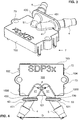
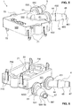
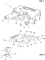
- FIGS 4 to 7 show a second embodiment of the adaptor device 1 according to invention.
- the same features are designated with the same numerals.
- the second embodiment differs from the above-described first embodiment in the design of the abutment 438 and 43, 53, respectively.
- the abutment consists of two separate elongated abutment rings 43, 53.
- the abutment rings 43, 53 have the same orientation and arrangement as the abutment plate 438 and are also designed to form a gap 1000 for receiving the further wall structure as explained in the context of the first embodiment.
- Figure 10 shows the conventional pressure sensor package 8 arranged on the printed circuit board 84.
- the package 8 comprises a basic body 83 with the first and second coupling nozzles 81, 82.
- the first and second coupling nozzles 81, 82 are the pneumatic ports receiving the fluid pressure to be measured by means of the sensor.
- the shape of the sub-cavity 22 is chosen such that the package 8 with its body 83 and nozzles 81, 82 properly fit thereinto, i.e. the outer shape of the package 8 and the shape of the sub-cavity 22 correspond to one another.
Description
- The present invention relates to a differential pressure sensor that comprises an adaptor device for establishing a connection between a further device with hose connectors and at least one hose, the further device being a differential pressure sensor package of the differential pressure sensor.
- Some differential pressure sensor devices have two or more coupling nozzles for connecting proximal ends of hoses for the purpose of creating an exclusive fluid communication between the coupling nozzles and distal hose ends.
US 2009/0194831 A1 discloses a differential pressure sensor device with two coupling nozzles, wherein a housing is configured to directly connect to a printed circuit board assembly and a pressure die is mounted on the printed circuit board assembly. The hoses - e.g. hoses from silicone or rubber - are often consumer goods and have a predetermined cross-section and material thickness. Hose material and material thickness may generally be optimized to the specific purpose of the device they are connected to. It may also be that a specific hose type shall be used as it is easily available. In order to ensure connectivity, the hose thickness has, however, to fulfill the following requirement: It shall be less than half of the distance between the two neighboring coupling nozzles to be connected; else the hoses do not fit both on the same device at the same time. Accordingly, either a specific device geometry is necessary for a given hose type or a specific hose type is necessary for a given device geometry. -
US 2013/0319556 A1 discloses inter alia, a bypass manifold for a water treatment system. The bypass manifold may have inlets and outlets that are differently spaced. -
US 2015/0145240 A1 discloses, inter alia, a thermal relief valve assembly having two inlet ports and two outlet ports, the inlet ports and outlet ports being differently spaced. -
DE 40 32 562 A1 -
EP 1 451 417 B1 -
WO 2016/090493 A1 discloses a flow splitter comprising a plurality of passages through a one-piece body. - Accordingly, it is an object of the present invention to overcome the above stated disadvantages and to provide a technical solution such that the same device with a given coupling nozzle arrangement is connectable to an increased number of types of hoses.
- This problem is solved by a differential pressure sensor according to
claim 1. - The present invention provides a differential pressure sensor comprising a differential pressure sensor package comprising a first hose coupling nozzle and a second hose coupling nozzle, the differential pressure sensor further comprising an adaptor device comprising a base body. The base body itself provides a first reception for receiving the first hose coupling nozzle and a second reception for receiving the second hose coupling nozzle.
- The first and second receptions are spaced apart from one another by a first distance.
- The adaptor device further comprises a first connecting nipple for receiving a first hose, i.e. a hose portion may be pushed thereon. The first connecting nipple has, at its distal end (i.e. away from the base body), a first muzzle opening. Moreover, the first connecting nipple is attached to the base body and connected to the first reception by a first passage such as to establish a continuous channel from the respective reception to the respective muzzle opening.
- The adaptor device further comprises a second connecting nipple for receiving a second hose. The second connecting nipple has, at its distal end, a second muzzle opening and is attached to the base body and connected to the second reception by a second passage.
- The first and second passages are continuous and fluidly connect the first and second muzzle openings to the first and second receptions, respectively. Moreover, the first and second muzzle openings are spaced apart at a second distance.
- The adaptor device is configured to be connected to the differential pressure sensor package, in particular to a (printed) circuit board of the differential pressure sensor package, The adaptor device can be actually attached to the differential pressure sensor package. The coupling nozzles can be the pneumatic connectors of the differential pressure sensor package. In the following, the differential pressure sensor package will also be referred to as the "further device".
- The adaptor device is configured to receive, upon connection with the further device, the first and second hose coupling nozzles in the first and second receptions, respectively, preferably in a fluid-tight manner. In order to easily accommodate hoses of different material thickness, the second distance now longer than the first distance.
- In some embodiments, the second distance is at least 30% longer, more preferably at least 50% longer, more preferably at least 100% or at least 200% longer, most preferably at least 5-times to 7-times longer than the first distance.
- In some embodiments the first distance is smaller than 15 millimeters, preferably smaller than 10 millimeters, most preferably less than or equal to 5 millimeters.
- In the context of the present invention, the term "adaptor device" refers to a coupling structure - preferably a single-piece unit, e.g. a molded piece - that may be arranged over the further device, whilst receiving the first and second coupling nozzle in the first and second receptions, respectively, such that the fluid outlet of the coupling nozzles is connected to the muzzle openings of the connecting nipples. In other words: The adaptor device is an extension structure that enlarges the distance of the ports to be connected to a hose such that thicker hoses or hoses with thicker material may be used.
- It is to be understood that an exterior diameter of the connecting nipple may also be change, e.g. increased such that hoses with thicker inner diameters may be used.
- In the context of the present invention, the term "base body" refers to the frame structure that accommodates the receptions and the connecting nipples and allows for connecting the adaptor device to the further device in a direct or indirect manner.
- In the context of the present invention, the term "reception" refers to a receiving structure that is configured to receive the coupling nozzle and preferably allows for a substantially fluid-tight connection between coupling nozzle and the respective first or second passage. Preferably, the receptions are cavities that are at least partly or completely circumferentially limited by wall structures, the wall structures providing lateral abutment to the received coupling nozzle such that as to stabilize the coupling nozzle in the reception. Sealing elements may be used to tighten the connection.
- In the context of the present invention, the terms "coupling nozzle" and "connecting nipple" refer each to a connector part for receiving a terminal open portion of a hose, the hose being preferably flexible, e.g. made from silicone, rubber, or plastics.
- In the context of the present invention, the term "further device" refers to a differential pressure sensor package that comprises coupling nozzles that shall be connected to hose-like structures for probing distant fluid conditions. The coupling nozzles can be two pneumatic ports.
- The present invention is based on the insight that an adaptor device may be used to increase the distance between the coupling nozzles of a complete sensor package by providing receptions for the coupling nozzles and connecting nipples that are, at least a their muzzle openings, further apart further apart from one another than the coupling nozzles are.
- It is to be understood that the basic body may have any shape such as a circular or round disc shape or it may be a convex polytope.
- In some preferred embodiments, the basic body has a part or complete cuboidal shape with cuboid faces. Preferably, the first and second connecting nipples are arranged on the same first cuboid face of the cuboid faces, wherein the first and second receptions are arranged on the same second cuboid face of the cuboid faces, the first cuboid face being different from the second cuboid face. The receptions may be arranged on a bottom face while the connecting nipples may be arranged on a lateral face or on the top face of the base body.
- In some embodiments, the first and second connecting nipples have first and second longitudinal nipple axes, respectively, wherein the first and second longitudinal nipple axes are straight and extend in an inclined manner with respect to one another. Preferably, the the first and second longitudinal nipple axes form a V shape extending from the base body.
- The V shape may have an opening angle that ranges from 10 degrees to 165 degrees, preferably, said opening angle ranges between 45 degrees and 120 degrees, more preferably between 60 degrees and 100 degrees, e.g.: 60 degrees or 90 degrees. The opening angle depends on the target second distance which, in turn, depends on the length of the first and second connecting nipples.
- The V shape may preferably be symmetrical with respect to the front-back axis of the basic body (see below). It may, however, also be asymmetric, i.e. one arm of the V shape may be further bent outwardly than the other. Accordingly, it is also contemplated that one connecting nipple extends normally, i.e. perpendicularly, or in plane, i.e. parallel, from the face it is attached to, while the other connecting nipple is inclined to said face and the one connecting nipple.
- Moreover, in general, lengths of the first and second connecting nipples, respectively, may be the same or may be different from one another, e.g. by at least 5%, 10%, 50%, or 100%. Also, a diameter of the first and second connecting nipples may be the same or may be different, e.g. by at least 5%, 10%, 50%, or 100%.
- The geometry may depend on the specific design of the further device and/or on the purpose of the latter and on the hoses to be used.
- In some embodiments, the first and second connecting nipples are not or not entirely straight but are bent and/or have steps along their longitudinal extension. Accordingly, the connecting nipples may have any form between the receptions and the muzzle openings.
- In some embodiments, the first and second receptions have, on their depth or on a step along the extension, a sealing element for forming the fluid-tight connection with the first and second hose coupling nozzles. This sealing element may be a sealing ring or piece that may be made from an elastic material and matches the shape of the cross-section of the coupling nozzle.
- In some embodiments, the first and second receptions have first and second longitudinal reception axes, respectively, wherein the first and second longitudinal reception axes extend parallel to on another. Preferably, the first and second longitudinal reception axes are straight for receiving straight coupling nozzles. The cross-sectional shape of the receptions may be similar as the cross-sectional shape of the coupling nozzle to be received. Preferably, the cross-sectional shapes of the receptions as well as of the connecting nipples are round, e.g. they have the shape of a straight or at least partly bent cylinder.
- In some embodiments the first and second longitudinal reception axes span a second plane. The second plane may extend parallel to one of the cuboid faces of the basic body.
- In some embodiments, the first and second longitudinal nipple axes span a first plane, wherein the first plane and the second plane intersect one another, wherein an intersection angle between the first plane and the second plane preferably ranges between 45 degrees to 165 degrees; wherein an intersecting line of the first plane and the second plane extends preferably parallel to a connection line of the first and second muzzle openings of the connecting nipples, or parallel the second cuboid face and/or wherein the intersection angle is preferably 120 degrees or smaller, e.g. 90 degrees.
- In some embodiments, the first and second connecting nipples are provided with an abutment, the abutment having at least one proximal face facing the tip of the connecting nipple and at least one distal face facing the other way. The first and second longitudinal nipple axes preferably intersect with the at least one proximal and distal faces. The abutment provides a stop for a hose that is pushed partially over the connecting nipple.
- Preferably, the abutment is elongated in a direction of the second distance, i.e. along the connecting line of the first and second muzzle openings. The elongation minimizes a height of the adaptor device whilst ensuring a secure stop surface in the elongation direction.
- The abutment may be at least one or several plate-like elements.
- In some embodiments, the abutment comprises at least two abutment rings, wherein on each of the first and second connecting nipples is arranged at least one abutment ring. The abutment ring then at least partially or completely circumferentially surrounds the connecting nipple. The outer shape of the abutment rings may be at least in part or completely round, preferably circular or elliptical, or have a polygonal shape.
- In some embodiments, the proximal and distal faces of the abutment extend parallel to one of the cuboid faces of the basic body. Alternatively, the distal and/or proximal faces of the abutment extend perpendicularly to the longitudinal extension of the connecting nipple.
- Moreover, the proximal face may be arranged at a distance to the one of the cuboid faces. Thereby, a gap is formed between said cuboid face and the proximal face of the abutment, the gap being adapted for receiving portions of a further wall structure. The further wall structure may be the housing of a larger device containing the second device. Thereby, the connecting nipples extend through the further wall structure, and may be engaged from the outside while the adapter device and the further wall structure are engaged in at least a partial positive locking manner, preferably also in an additional force fit.
- The base body has a cavity and the first and second receptions are arranged in said cavity. Preferably, a reception structure is additionally arranged in the cavity such as to at least partially surround the first and second receptions. The reception structure preferably delimits a sub-cavity within the cavity, the sub-cavity being shaped for receiving the further device, e.g., the differential pressure sensor package with the first and second coupling nozzles, or parts thereof. The sub-cavity may have a substantially cuboidal shape.
- In some embodiments, the adapter device further comprises at least one first fastening structure for connecting the adaptor device to the further device, in particular to a circuit board of the further device. Preferably, these fastening structures are quick-release coupling elements for easy and quick connection of the adaptor device with the further device, the latter carrying the second fastening structure.
- Preferably, the at least one first fastening structure comprises at least one, preferably a plurality of snap-in tongues with a snap-in nose and/or at least one a through-hole through the basic body for connecting the adaptor device to the further device by means of bolts such as screws or the like. Soldering connections may also be provided through the through-hole. The first fastening structure may, for example, be selected from the group comprising: glue surfaces, bolt connections, screw connections, and hook connections of any kind.
- In some embodiments, the first and second connecting nipples each comprise an attachment portion, the attachment portion being a pipe portion extending along the first and second nipple axes, respectively, and being attached to the first cuboid face of the base body. The first and second nipple axes extend preferably parallel to the first cuboid face.
- The free tip portions of the connecting nipples may be provided with a retention structure for securely engaging the hose portion. The retention structure may comprise, e.g., at least one rim, ring, or rib, extending at least partially circumferentially around the connecting nipple and extending in radial direction.
- In some preferred embodiments, the adaptor device is a single-piece element, preferably a molded piece. Any or some of the edges of the adaptor device may rounded such as to avoid damage to the hose.
- Preferred embodiments of the invention are described in the following with reference to the drawings, which are for the purpose of illustrating the present preferred embodiments of the invention and not for the purpose of limiting the same. In the drawings,
- Fig. 1
- shows a perspective top front view of a preferred embodiment of the adaptor device according to invention;
- Fig. 2
- shows the adaptor device according to
Fig. 1 in a bottom view; - Fig. 3
- shows the adaptor device according to
Fig. 1 in a perspective top rear view; - Fig. 4
- shows, in a top view, a further embodiment of the adaptor device according to invention;
- Fig. 5
- shows a perspective top rear view of the embodiment of the adaptor device according to
Fig. 4 ; - Fig. 6
- shows of the perspective bottom front view of the embodiment of the adaptor device according to
Fig. 4 ; - Fig. 7
- shows a further perspective top front view of the embodiment of the adaptor device according to
Fig. 4 ; - Fig. 8
- shows a detail of a cross-sectional view of the adaptor device with an increased detail of
Fig. 8 to the left; - Fig. 9
- shows a further detail of a cross-sectional view of the adaptor device; and
- Fig. 10
- shows a perspective top view of a conventional differential pressure sensor package.
- Preferred embodiments are now described with reference to
Figures 1 to 10 . -
Figures 1 to 3 show a first embodiment of theadaptor device 1 according to invention in a perspective top front view, a bottom view, and a perspective top rear view, respectively. - The
adaptor device 1 features abasic body 10 with a cuboidal shape and is sized in the cm range, e.g.: 6 cm x 7 cm x 1 cm. Thebase body 10 includes a top wall with atop face 100, a front wall with afront face 101, two side walls with lateral side faces 102, 104, and a rear wall with arear face 103. There is no extra bottom wall such that thebottom face 105 is actually the bottom face of the top wall. - The box-
like base body 10 delimits a substantially cuboidalbottom cavity 106 which is open toward the bottom (cf.Fig. 2 ). - The
basic body 10 further comprises first andsecond receptions second coupling nozzles Fig. 10 ), first and second connectingnipples first fastening structure 7 for connection with a printed circuit board 84 (cf.Fig. 10 ) on which thepackage 8 is arranged on. - The first and second connecting
nipples attachment portions intermediate portions abutment 438 arranged therebetween, sealing rings 45, 55, andtip portions nipples - The
tip portions distal edges muzzle openings nipple tip portions proximal ends - Proximal of the proximal ends 460, 560 of the
tip portions nipples adaptor device 1 and the connected hoses. - Further straight pipe portions, the first and second
intermediate portions intermediate portions tip portions - The
attachment sections top face 101, whereby the first and second connectingnipples base body 10. - The first and second connecting
nipples Fig. 2 ). The first and second longitudinal nipple axes 48, 58 form a V shape with an opening angle from 50 degrees to 70 degrees, e.g. 60 degrees. The first and secondlongitudinal axes top face 100. - The first and second connecting
nipples second muzzle openings second attachment portions second receptions second receptions Fig. 2 (andFig. 4 for the second embodiment, see below). The first distance d is about 6-times smaller than the second distance D. The second distance D may be 3 centimeters to 6 centimeters. - The
single abutment plate 438 is arranged between the first and secondintermediate portions nipples abutment plate 438 extends parallel to thefront face 101. The longitudinal nipple axes 48, 58 intersect theabutment plate 438 and extend angular to the plane defined by theabutment plate 438. - The
abutment plate 438 is an elongated shield with rounded short edges that acts as a stop for hose parts pushed over the sealing rings 45, 55. For that purpose, adistal face 431 is provided on theabutment plate 438. As can be seen from the Figures, thedistal face 431 extends parallel to thefront face 101 of thebase body 10. - Moreover, due to the extension first intermediate section 42, 52, a
gap 1000 is created between aproximal face 430 of theabutment plate 438 and thefront face 101 of thebase body 10. Thisgap 1000 may be used for receiving a wall structure of, for example, a housing of the unit comprising theadaptor device 1 and the differentialpressure sensor package 8 on the printed circuit board to which thepackage 8 is attached to. Thereby, the connectingnipples abutment plate 438 in a partial positive locking with the further wall structure whilst being usable from the exterior of the further wall structure. - The first and
second receptions Figures 8 and9 .Figure 8 shows a detail of a cross-section (front to back) of theadaptor device 1.Figure 9 shows a second cross-section (side to side) through thesecond reception 3. Thefirst reception 2 has the same design. - The first and
second receptions front face 101. Accordingly, the second plane P2 intersects with the first plane P1 at a 90 degrees angle, wherein the intersection line is parallel to both the top and the front faces 100, 101. - The first and
second receptions bottom cavity 106 to the passage portions in theattachment portions receptions receptions 2, 3 (cf.Fig. 8 ). Thereceptions receptions respective attachments portion receptions Fig. 8 ) to be inserted, wherein the ring-like sealing elements 24 abut against a stop surface created by the steps. The first andsecond coupling nozzles elements 24 and are received in a positive locking manner in radial direction. - The first and
second passages receptions nipples second muzzle openings - The
adaptor device 1 further has afirst fastening structure 7 that comprises four snap-intongues 71. The snap-in tongues carry, on their free end portions, outward facing snap-innoses 72. The snap-intongues 71 are elastic members for establishing a quick-release connection to the differentialpressure sensor package 8. Thepackage 8 is mounted on a printed circuit board 84 (cf.Fig. 10 ), the latter being provided with a second fastening structure. The second fastening structure is a set ofopenings 840 for receiving portions of the snap-intongues 71 such that the snap-innoses 72 extend into the printedcircuits board 84 and engage with appropriate stop faces provided in theopenings 840. As can be seen from the Figures, the four snap-intongues 71 are arranged in corner regions of thebottom face 105. Thetongues 71 are prolonged into the side walls of thebase body 10 bylateral slots 710. The Figures also show that thetongues 71 protrude beyond the bottom edge of the side walls such that the snap-innoses 72 may be inserted into the above-mentionedopenings 840 in the printedcircuit board 84. - For further securing the
adaptor device 1 to the printedcircuit board 84, two lateral through-openings 73 are provided in thebase body 10. The through-openings 73 are delimited by hollow cylinders that are arranged to intersect the side walls of thebase body 10. Moreover, the hollow cylinders are arranged between a pair of snap-intongues 71. Furthermore, the hollow cylinders protrude perpendicularly to and from thebottom face 105 and laterally beyond the side walls of thebase body 10 such that a part cylindrical outward-facing protrusion is evident on the side walls. Moreover, the hollow cylinders are reinforced by stiffeningwalls 730 arranged in thecavity 106 as shown, for example, inFig. 2 . - In the
cavity 106 is arranged areception structure 21 with twoside walls 211 and one rear wall 212. Thereception structure 21 together with an intermediate portion of thefront wall 101 form another box-like structure, delimiting a substantiallycuboidal sub-cavity 22 within thecavity 106. The sub-cavity 22 is also open to the bottom. - In the sub-cavity 22, the first and
second receptions -
Figures 4 to 7 show a second embodiment of theadaptor device 1 according to invention. The same features are designated with the same numerals. The second embodiment differs from the above-described first embodiment in the design of theabutment abutment plate 438 and are also designed to form agap 1000 for receiving the further wall structure as explained in the context of the first embodiment. -
Figure 10 shows the conventionalpressure sensor package 8 arranged on the printedcircuit board 84. Thepackage 8 comprises abasic body 83 with the first andsecond coupling nozzles second coupling nozzles package 8 with itsbody 83 andnozzles package 8 and the shape of the sub-cavity 22 correspond to one another.LIST OF REFERENCE SIGNS 1 adaptor device 431 distal face of 43 44 second intermediate portion of 4 10 base body 45 sealing ring of 4 100 top face of 10 450 locking face of 45 101 front face of 10 46 tip portion of 4 102 first side face of 10 460 proximal end of 46 103 rear face of 10 461 distal edge of 46 104 second side face of 10 47 muzzle opening of 4 105 bottom face of 10 48 first longitudinal axis of 4 106 bottom cavity of 10 5 second connecting nipple 1000 gap 50 second passage in 5 51 attachment portion of 5 2 first reception 52 first intermediate portion of 5 20 first abutment 53 abutment ring of 5 21 reception structure 530 proximal face of 53 22 sub-cavity within 106 531 distal face of 53 23 longitudinal axis of 2 54 second intermediate portion of 5 24 ring-like sealing element 55 sealing ring of 5 3 second reception 550 locking face of 55 30 second abutment 56 tip portion of 5 33 longitudinal axis of 3 560 proximal end of 56 561 distal edge of 56 4 first connecting nipple 57 muzzle opening of 5 40 first passage in 4 58 second longitudinal axis of 5 41 attachment portion of 4 42 first intermediate portion of 4 7 first fastening structure 43 abutment ring of 4 438 abutment plate 430 proximal face of 43 71 snap-in tongue 83 base body of 8 710 slot 84 printed circuit board 72 snap-in nose 840 opening in 84 for receiving 72 73 through-hole 730 stiffening rib or wall d first distance between 2, 3 D second distance between 47, 57 8 differential pressure sensor package 81 fist coupling nozzle of 8 82 second coupling nozzle of 8
Claims (15)
- A differential pressure sensor comprising:a differential pressure sensor package (8) comprising a first hose coupling nozzle (81) and a second hose coupling nozzle (82),wherein the differential pressure sensor comprises an adaptor device (1) comprising:a base body (10), the base body (10) comprising a first reception (2) for receiving the first hose coupling nozzle (81) and a second reception (3) for receiving the second hose coupling nozzle (82), wherein the first and second receptions (2,3) are spaced apart from one another by a first distance (d);a first connecting nipple (4) for receiving a first hose, the first connecting nipple (4) having a first muzzle opening (47) and being attached to the base body (10) and connected to the first reception (2) by a first passage (40); anda second connecting nipple (5) for receiving a second hose, the second connecting nipple (5) having a second muzzle opening (57) and being attached to the base body (10) and connected to the second reception (3) by a second passage (50), wherein the first and second muzzle openings (47,57) are spaced apart at a second distance (D), wherein the second distance (D) is longer than the first distance (d);wherein the adaptor device (1) is configured to be connected to the differential pressure sensor package (8), and wherein the adaptor device (1) is further configured to receive, upon connection with the differential pressure sensor package (8), the first and second hose coupling nozzles (81,82) in the first and second receptions (2,3), respectively.
- The differential pressure sensor according to claim 1, wherein the second distance (D) is at least 30% longer, more preferably at least 50% longer, more preferably at least 100% longer, most preferably 5-times to 7-times longer than the first distance (d), and/or wherein the first distance (d) is smaller than 15 millimeters, preferably smaller than 10 millimeters, most preferably less than or equal to 5 millimeters.
- The differential pressure sensor of claim 1 or 2, wherein the base body has a cavity (106), and wherein the first and second receptions (2,3) are arranged in the cavity (106).
- The differential pressure sensor according to any one of claims 1 to 3, wherein the base body (10) has a part or complete cuboidal shape with cuboid faces (100-105); wherein the first and second connecting nipples (4,5) are arranged on the same first cuboid face (100) of the cuboid faces (100-105); and
wherein the first and second receptions (2,3) are arranged on the same second cuboid face (101) of the cuboid faces (100-105), the first cuboid face (100) being different from the second cuboid face (101). - The differential pressure sensor according to claim 4, wherein the first and second connecting nipples (4,5) have first and second longitudinal nipple axes (48,58), respectively, wherein the first and second connecting nipples (4,5) each comprise an attachment portion (41,51), the attachment portions (41,51) being pipe portions extending along the first and second nipple axes (48,58), respectively, and being attached to the first cuboid face (100) of the base body (10), and wherein the first and second nipple axes (48,58) extend parallel to the first cuboid face (100).
- The differential pressure sensor according to any one of the preceding claims, wherein the first and second connecting nipples (4,5) have first and second longitudinal nipple axes (48,58), respectively, and wherein the first and second longitudinal nipple axes (48,58) are straight and extend in an inclined manner with respect to one another, preferably in a V shape.
- The differential pressure sensor according to claim 6,
wherein the first and second longitudinal nipple axes (48,58) span a first plane (P1),
wherein the first and second receptions (2,3) have first and second longitudinal reception axes (23,33), respectively, wherein the first and second longitudinal reception axes (23,33) extend parallel to one another and span a second plane (P2),
wherein the first plane (P1) and the second plane (P2) intersect one another, wherein an intersection angle between the first plane (P1) and the second plane (P2) ranges between 45 degrees to 165 degrees. - The differential pressure sensor according to any one of the preceding claims, wherein the first and second receptions (2,3) have, on their depth, a sealing element (24) for forming a fluid tight connection with the first and second hose coupling nozzles (81,82); or
wherein the first and second receptions (2,3) have first and second longitudinal reception axes (23,33), respectively, wherein the first and second longitudinal reception axes (23,33) extend parallel to one another and are preferably straight. - The differential pressure sensor according to claim 4 in combination with claim 6, wherein the first and second receptions (2,3) have first and second longitudinal reception axes (23,33), respectively, wherein the first and second longitudinal reception axes (23,33) extend parallel to one another and span a second plane (P2), and wherein the second plane (P2) is parallel to the second cuboid face (101) of the base body (10).
- The differential pressure sensor according to any one of the preceding claims, wherein the first and second connecting nipples (4,5) are provided with an abutment (438; 43,53), the abutment (438; 43,53) having at least one proximal face (430,530) and at least one distal face (431,531), wherein the first and second longitudinal nipple axes (48,58) intersect with the at least one proximal and distal faces (430,431,530,531), and wherein the abutment is preferably elongated in a direction of the second distance (D).
- The differential pressure sensor according to claim 10, wherein the abutment (43,53) comprises at least two abutment rings (43,53), wherein on each of the first and second connecting nipples (4,5) is arranged at least one abutment ring (43,53), the abutment rings (43,53) being preferably plate-like and at least in part or completely round, preferably circular or elliptical, or having a polygonal shape.
- The differential pressure sensor according to claim 4 in combination with at least one of claims 10 and 11, wherein the proximal and distal faces (430,431,530,531) of the abutment (43,53) extend parallel to one of the cuboid faces (100-105) of the base body (10), and wherein the proximal face (430,530) is arranged at a distance to the one of the cuboid faces (100-105) such that a gap (1000) is formed between the second cuboid face (101) and the proximal face (530) for receiving portions of a further wall structure.
- The differential pressure sensor according to claim 3, preferably in combination with at least one of claims 2 and 4 to 12, wherein a reception structure (21) is arranged in the cavity (106) around the first and second receptions (2,3), the reception structure (21) forming a sub-cavity (22) for receiving the differential pressure sensor package (8) with the first and second coupling nozzles (81,82).
- The differential pressure sensor according to any one of the preceding claims, comprising at least one first fastening structure (7) for connecting the adaptor device (1) to the differential pressure sensor package (8), in particular to a circuit board (84) of the differential pressure sensor package (8).
- The differential pressure sensor according to claim 14, wherein the at least one first fastening structure (7) comprises at least one, preferably a plurality of snap-in tongues (71) with a snap-in nose (72) and/or at least one through-hole (73) through the base body (10) for connecting the adaptor device (1) to the differential pressure sensor package (8).
Priority Applications (2)
| Application Number | Priority Date | Filing Date | Title |
|---|---|---|---|
| EP16181714.3A EP3276242B1 (en) | 2016-07-28 | 2016-07-28 | Differential pressure sensor comprising an adaptor device |
| US15/660,351 US20180031159A1 (en) | 2016-07-28 | 2017-07-26 | Adaptor device |
Applications Claiming Priority (1)
| Application Number | Priority Date | Filing Date | Title |
|---|---|---|---|
| EP16181714.3A EP3276242B1 (en) | 2016-07-28 | 2016-07-28 | Differential pressure sensor comprising an adaptor device |
Publications (2)
| Publication Number | Publication Date |
|---|---|
| EP3276242A1 EP3276242A1 (en) | 2018-01-31 |
| EP3276242B1 true EP3276242B1 (en) | 2019-08-28 |
Family
ID=56802235
Family Applications (1)
| Application Number | Title | Priority Date | Filing Date |
|---|---|---|---|
| EP16181714.3A Active EP3276242B1 (en) | 2016-07-28 | 2016-07-28 | Differential pressure sensor comprising an adaptor device |
Country Status (2)
| Country | Link |
|---|---|
| US (1) | US20180031159A1 (en) |
| EP (1) | EP3276242B1 (en) |
Families Citing this family (2)
| Publication number | Priority date | Publication date | Assignee | Title |
|---|---|---|---|---|
| PL3588043T3 (en) | 2018-06-28 | 2020-11-30 | Ovh | Fluid circuit monitoring system |
| US11703408B1 (en) * | 2020-04-30 | 2023-07-18 | Senva, Inc. | Versatilely mountable pressure sensing apparatus, system, and/or method |
Citations (1)
| Publication number | Priority date | Publication date | Assignee | Title |
|---|---|---|---|---|
| WO2016090493A1 (en) * | 2014-12-12 | 2016-06-16 | Luxfer Canada Ltd | Flow splitter |
Family Cites Families (12)
| Publication number | Priority date | Publication date | Assignee | Title |
|---|---|---|---|---|
| DE4032562C2 (en) * | 1990-10-13 | 1999-03-11 | Werner Kotzab | Distribution arrangement |
| US6564642B1 (en) * | 2000-11-02 | 2003-05-20 | Kavlico Corporation | Stable differential pressure measuring system |
| US6591674B2 (en) * | 2000-12-21 | 2003-07-15 | Honeywell International Inc. | System for sensing the motion or pressure of a fluid, the system having dimensions less than 1.5 inches, a metal lead frame with a coefficient of thermal expansion that is less than that of the body, or two rtds and a heat source |
| AUPR695801A0 (en) * | 2001-08-10 | 2001-09-06 | Caroma Industries Limited | An ultra-low volume gravity flushing toilet |
| DE10223357A1 (en) * | 2002-05-25 | 2003-12-04 | Bosch Gmbh Robert | Pressure measuring device |
| US20090194831A1 (en) * | 2008-02-01 | 2009-08-06 | Custom Sensors & Technologies, Inc. | Integrated cavity in pcb pressure sensor |
| US8827317B2 (en) * | 2010-05-07 | 2014-09-09 | Welch Allyn, Inc. | Medical device adaptor |
| US20120205907A1 (en) * | 2011-02-16 | 2012-08-16 | Westendorf Manufacturing Co., Inc. | Hydraulic line attachment device and method |
| US20130319556A1 (en) * | 2011-11-23 | 2013-12-05 | R.E. Prescott Co., Inc. | Universal interface connection system and flow directing coupling system and manifold using same |
| US20150051536A1 (en) * | 2012-03-21 | 2015-02-19 | Yair Mendels | Extensionless reversible connection catheter apparatus |
| JP6079206B2 (en) * | 2012-12-18 | 2017-02-15 | 株式会社デンソー | Pressure sensor |
| WO2015081291A1 (en) * | 2013-11-27 | 2015-06-04 | Kujawski Anthony | A fluid coupling with lock connection |
-
2016
- 2016-07-28 EP EP16181714.3A patent/EP3276242B1/en active Active
-
2017
- 2017-07-26 US US15/660,351 patent/US20180031159A1/en not_active Abandoned
Patent Citations (1)
| Publication number | Priority date | Publication date | Assignee | Title |
|---|---|---|---|---|
| WO2016090493A1 (en) * | 2014-12-12 | 2016-06-16 | Luxfer Canada Ltd | Flow splitter |
Also Published As
| Publication number | Publication date |
|---|---|
| EP3276242A1 (en) | 2018-01-31 |
| US20180031159A1 (en) | 2018-02-01 |
Similar Documents
| Publication | Publication Date | Title |
|---|---|---|
| US8256801B2 (en) | Coupling device for media conduits | |
| US10627034B2 (en) | Manifold apparatus | |
| EP3276242B1 (en) | Differential pressure sensor comprising an adaptor device | |
| KR101665739B1 (en) | Air bag module with t-diffuser for inflator | |
| AU2018375417B2 (en) | Coupler for light fixture | |
| US20160131294A1 (en) | Quick connect pneumatic coupler | |
| US20070241559A1 (en) | Joining arrangement for connecting a pipe to a system | |
| US20170207505A1 (en) | Hose made from an elastic material | |
| WO2004024387B1 (en) | Mat ramp securement and method | |
| US4722559A (en) | Spray hose assembly | |
| US20210003236A1 (en) | Multi-lumen hose and connector nipple | |
| US20020125716A1 (en) | Fitting and pipe section for jetted bath heaters | |
| US7296551B2 (en) | Intake manifold | |
| KR100543135B1 (en) | structure of hose clamping | |
| AU2016399224B2 (en) | Tap connector with flow stabilization | |
| US20220394941A1 (en) | Emitter and drip irrigation tube | |
| KR200491556Y1 (en) | Pipe Connector for Pump | |
| KR20120006255U (en) | a coupler for agriculture | |
| CN212718625U (en) | Adapting PE drain pipe | |
| JP2010133653A (en) | Outer pipe connecting device of hot water supply port adaptor for bathtub | |
| US20200271079A1 (en) | Rail for high-pressure direct injection | |
| CN217874719U (en) | Drainage pipe anti-drop buckle formula connects | |
| EP1075067A1 (en) | Tube connector | |
| EP4012241A1 (en) | Pipe branch structure | |
| KR102575883B1 (en) | Engaging flange for pipe of airconditioner |
Legal Events
| Date | Code | Title | Description |
|---|---|---|---|
| PUAI | Public reference made under article 153(3) epc to a published international application that has entered the european phase |
Free format text: ORIGINAL CODE: 0009012 |
|
| STAA | Information on the status of an ep patent application or granted ep patent |
Free format text: STATUS: THE APPLICATION HAS BEEN PUBLISHED |
|
| AK | Designated contracting states |
Kind code of ref document: A1 Designated state(s): AL AT BE BG CH CY CZ DE DK EE ES FI FR GB GR HR HU IE IS IT LI LT LU LV MC MK MT NL NO PL PT RO RS SE SI SK SM TR |
|
| AX | Request for extension of the european patent |
Extension state: BA ME |
|
| STAA | Information on the status of an ep patent application or granted ep patent |
Free format text: STATUS: REQUEST FOR EXAMINATION WAS MADE |
|
| 17P | Request for examination filed |
Effective date: 20180420 |
|
| RBV | Designated contracting states (corrected) |
Designated state(s): AL AT BE BG CH CY CZ DE DK EE ES FI FR GB GR HR HU IE IS IT LI LT LU LV MC MK MT NL NO PL PT RO RS SE SI SK SM TR |
|
| STAA | Information on the status of an ep patent application or granted ep patent |
Free format text: STATUS: EXAMINATION IS IN PROGRESS |
|
| 17Q | First examination report despatched |
Effective date: 20180920 |
|
| GRAP | Despatch of communication of intention to grant a patent |
Free format text: ORIGINAL CODE: EPIDOSNIGR1 |
|
| STAA | Information on the status of an ep patent application or granted ep patent |
Free format text: STATUS: GRANT OF PATENT IS INTENDED |
|
| RIC1 | Information provided on ipc code assigned before grant |
Ipc: F16L 41/00 20060101AFI20190201BHEP Ipc: F16L 33/30 20060101ALI20190201BHEP Ipc: F16L 25/14 20060101ALN20190201BHEP Ipc: F16L 39/02 20060101ALI20190201BHEP Ipc: G01L 19/00 20060101ALI20190201BHEP Ipc: F16L 41/03 20060101ALI20190201BHEP |
|
| INTG | Intention to grant announced |
Effective date: 20190311 |
|
| GRAS | Grant fee paid |
Free format text: ORIGINAL CODE: EPIDOSNIGR3 |
|
| GRAA | (expected) grant |
Free format text: ORIGINAL CODE: 0009210 |
|
| STAA | Information on the status of an ep patent application or granted ep patent |
Free format text: STATUS: THE PATENT HAS BEEN GRANTED |
|
| AK | Designated contracting states |
Kind code of ref document: B1 Designated state(s): AL AT BE BG CH CY CZ DE DK EE ES FI FR GB GR HR HU IE IS IT LI LT LU LV MC MK MT NL NO PL PT RO RS SE SI SK SM TR |
|
| REG | Reference to a national code |
Ref country code: GB Ref legal event code: FG4D |
|
| REG | Reference to a national code |
Ref country code: CH Ref legal event code: EP |
|
| REG | Reference to a national code |
Ref country code: AT Ref legal event code: REF Ref document number: 1172838 Country of ref document: AT Kind code of ref document: T Effective date: 20190915 |
|
| REG | Reference to a national code |
Ref country code: IE Ref legal event code: FG4D |
|
| REG | Reference to a national code |
Ref country code: DE Ref legal event code: R096 Ref document number: 602016019289 Country of ref document: DE |
|
| REG | Reference to a national code |
Ref country code: NL Ref legal event code: MP Effective date: 20190828 |
|
| REG | Reference to a national code |
Ref country code: LT Ref legal event code: MG4D |
|
| PG25 | Lapsed in a contracting state [announced via postgrant information from national office to epo] |
Ref country code: LT Free format text: LAPSE BECAUSE OF FAILURE TO SUBMIT A TRANSLATION OF THE DESCRIPTION OR TO PAY THE FEE WITHIN THE PRESCRIBED TIME-LIMIT Effective date: 20190828 Ref country code: HR Free format text: LAPSE BECAUSE OF FAILURE TO SUBMIT A TRANSLATION OF THE DESCRIPTION OR TO PAY THE FEE WITHIN THE PRESCRIBED TIME-LIMIT Effective date: 20190828 Ref country code: PT Free format text: LAPSE BECAUSE OF FAILURE TO SUBMIT A TRANSLATION OF THE DESCRIPTION OR TO PAY THE FEE WITHIN THE PRESCRIBED TIME-LIMIT Effective date: 20191230 Ref country code: NL Free format text: LAPSE BECAUSE OF FAILURE TO SUBMIT A TRANSLATION OF THE DESCRIPTION OR TO PAY THE FEE WITHIN THE PRESCRIBED TIME-LIMIT Effective date: 20190828 Ref country code: FI Free format text: LAPSE BECAUSE OF FAILURE TO SUBMIT A TRANSLATION OF THE DESCRIPTION OR TO PAY THE FEE WITHIN THE PRESCRIBED TIME-LIMIT Effective date: 20190828 Ref country code: SE Free format text: LAPSE BECAUSE OF FAILURE TO SUBMIT A TRANSLATION OF THE DESCRIPTION OR TO PAY THE FEE WITHIN THE PRESCRIBED TIME-LIMIT Effective date: 20190828 Ref country code: NO Free format text: LAPSE BECAUSE OF FAILURE TO SUBMIT A TRANSLATION OF THE DESCRIPTION OR TO PAY THE FEE WITHIN THE PRESCRIBED TIME-LIMIT Effective date: 20191128 Ref country code: BG Free format text: LAPSE BECAUSE OF FAILURE TO SUBMIT A TRANSLATION OF THE DESCRIPTION OR TO PAY THE FEE WITHIN THE PRESCRIBED TIME-LIMIT Effective date: 20191128 |
|
| PG25 | Lapsed in a contracting state [announced via postgrant information from national office to epo] |
Ref country code: RS Free format text: LAPSE BECAUSE OF FAILURE TO SUBMIT A TRANSLATION OF THE DESCRIPTION OR TO PAY THE FEE WITHIN THE PRESCRIBED TIME-LIMIT Effective date: 20190828 Ref country code: IS Free format text: LAPSE BECAUSE OF FAILURE TO SUBMIT A TRANSLATION OF THE DESCRIPTION OR TO PAY THE FEE WITHIN THE PRESCRIBED TIME-LIMIT Effective date: 20191228 Ref country code: LV Free format text: LAPSE BECAUSE OF FAILURE TO SUBMIT A TRANSLATION OF THE DESCRIPTION OR TO PAY THE FEE WITHIN THE PRESCRIBED TIME-LIMIT Effective date: 20190828 Ref country code: ES Free format text: LAPSE BECAUSE OF FAILURE TO SUBMIT A TRANSLATION OF THE DESCRIPTION OR TO PAY THE FEE WITHIN THE PRESCRIBED TIME-LIMIT Effective date: 20190828 Ref country code: AL Free format text: LAPSE BECAUSE OF FAILURE TO SUBMIT A TRANSLATION OF THE DESCRIPTION OR TO PAY THE FEE WITHIN THE PRESCRIBED TIME-LIMIT Effective date: 20190828 Ref country code: GR Free format text: LAPSE BECAUSE OF FAILURE TO SUBMIT A TRANSLATION OF THE DESCRIPTION OR TO PAY THE FEE WITHIN THE PRESCRIBED TIME-LIMIT Effective date: 20191129 |
|
| REG | Reference to a national code |
Ref country code: AT Ref legal event code: MK05 Ref document number: 1172838 Country of ref document: AT Kind code of ref document: T Effective date: 20190828 |
|
| PG25 | Lapsed in a contracting state [announced via postgrant information from national office to epo] |
Ref country code: TR Free format text: LAPSE BECAUSE OF FAILURE TO SUBMIT A TRANSLATION OF THE DESCRIPTION OR TO PAY THE FEE WITHIN THE PRESCRIBED TIME-LIMIT Effective date: 20190828 |
|
| PG25 | Lapsed in a contracting state [announced via postgrant information from national office to epo] |
Ref country code: AT Free format text: LAPSE BECAUSE OF FAILURE TO SUBMIT A TRANSLATION OF THE DESCRIPTION OR TO PAY THE FEE WITHIN THE PRESCRIBED TIME-LIMIT Effective date: 20190828 Ref country code: DK Free format text: LAPSE BECAUSE OF FAILURE TO SUBMIT A TRANSLATION OF THE DESCRIPTION OR TO PAY THE FEE WITHIN THE PRESCRIBED TIME-LIMIT Effective date: 20190828 Ref country code: EE Free format text: LAPSE BECAUSE OF FAILURE TO SUBMIT A TRANSLATION OF THE DESCRIPTION OR TO PAY THE FEE WITHIN THE PRESCRIBED TIME-LIMIT Effective date: 20190828 Ref country code: PL Free format text: LAPSE BECAUSE OF FAILURE TO SUBMIT A TRANSLATION OF THE DESCRIPTION OR TO PAY THE FEE WITHIN THE PRESCRIBED TIME-LIMIT Effective date: 20190828 Ref country code: IT Free format text: LAPSE BECAUSE OF FAILURE TO SUBMIT A TRANSLATION OF THE DESCRIPTION OR TO PAY THE FEE WITHIN THE PRESCRIBED TIME-LIMIT Effective date: 20190828 Ref country code: RO Free format text: LAPSE BECAUSE OF FAILURE TO SUBMIT A TRANSLATION OF THE DESCRIPTION OR TO PAY THE FEE WITHIN THE PRESCRIBED TIME-LIMIT Effective date: 20190828 |
|
| PG25 | Lapsed in a contracting state [announced via postgrant information from national office to epo] |
Ref country code: SM Free format text: LAPSE BECAUSE OF FAILURE TO SUBMIT A TRANSLATION OF THE DESCRIPTION OR TO PAY THE FEE WITHIN THE PRESCRIBED TIME-LIMIT Effective date: 20190828 Ref country code: SK Free format text: LAPSE BECAUSE OF FAILURE TO SUBMIT A TRANSLATION OF THE DESCRIPTION OR TO PAY THE FEE WITHIN THE PRESCRIBED TIME-LIMIT Effective date: 20190828 Ref country code: IS Free format text: LAPSE BECAUSE OF FAILURE TO SUBMIT A TRANSLATION OF THE DESCRIPTION OR TO PAY THE FEE WITHIN THE PRESCRIBED TIME-LIMIT Effective date: 20200224 Ref country code: CZ Free format text: LAPSE BECAUSE OF FAILURE TO SUBMIT A TRANSLATION OF THE DESCRIPTION OR TO PAY THE FEE WITHIN THE PRESCRIBED TIME-LIMIT Effective date: 20190828 |
|
| REG | Reference to a national code |
Ref country code: DE Ref legal event code: R097 Ref document number: 602016019289 Country of ref document: DE |
|
| PLBE | No opposition filed within time limit |
Free format text: ORIGINAL CODE: 0009261 |
|
| STAA | Information on the status of an ep patent application or granted ep patent |
Free format text: STATUS: NO OPPOSITION FILED WITHIN TIME LIMIT |
|
| PG2D | Information on lapse in contracting state deleted |
Ref country code: IS |
|
| 26N | No opposition filed |
Effective date: 20200603 |
|
| PG25 | Lapsed in a contracting state [announced via postgrant information from national office to epo] |
Ref country code: SI Free format text: LAPSE BECAUSE OF FAILURE TO SUBMIT A TRANSLATION OF THE DESCRIPTION OR TO PAY THE FEE WITHIN THE PRESCRIBED TIME-LIMIT Effective date: 20190828 |
|
| PG25 | Lapsed in a contracting state [announced via postgrant information from national office to epo] |
Ref country code: MC Free format text: LAPSE BECAUSE OF FAILURE TO SUBMIT A TRANSLATION OF THE DESCRIPTION OR TO PAY THE FEE WITHIN THE PRESCRIBED TIME-LIMIT Effective date: 20190828 |
|
| GBPC | Gb: european patent ceased through non-payment of renewal fee |
Effective date: 20200728 |
|
| REG | Reference to a national code |
Ref country code: BE Ref legal event code: MM Effective date: 20200731 |
|
| PG25 | Lapsed in a contracting state [announced via postgrant information from national office to epo] |
Ref country code: LU Free format text: LAPSE BECAUSE OF NON-PAYMENT OF DUE FEES Effective date: 20200728 Ref country code: FR Free format text: LAPSE BECAUSE OF NON-PAYMENT OF DUE FEES Effective date: 20200731 Ref country code: GB Free format text: LAPSE BECAUSE OF NON-PAYMENT OF DUE FEES Effective date: 20200728 |
|
| PG25 | Lapsed in a contracting state [announced via postgrant information from national office to epo] |
Ref country code: BE Free format text: LAPSE BECAUSE OF NON-PAYMENT OF DUE FEES Effective date: 20200731 |
|
| PG25 | Lapsed in a contracting state [announced via postgrant information from national office to epo] |
Ref country code: IE Free format text: LAPSE BECAUSE OF NON-PAYMENT OF DUE FEES Effective date: 20200728 |
|
| PG25 | Lapsed in a contracting state [announced via postgrant information from national office to epo] |
Ref country code: MT Free format text: LAPSE BECAUSE OF FAILURE TO SUBMIT A TRANSLATION OF THE DESCRIPTION OR TO PAY THE FEE WITHIN THE PRESCRIBED TIME-LIMIT Effective date: 20190828 Ref country code: CY Free format text: LAPSE BECAUSE OF FAILURE TO SUBMIT A TRANSLATION OF THE DESCRIPTION OR TO PAY THE FEE WITHIN THE PRESCRIBED TIME-LIMIT Effective date: 20190828 |
|
| PG25 | Lapsed in a contracting state [announced via postgrant information from national office to epo] |
Ref country code: MK Free format text: LAPSE BECAUSE OF FAILURE TO SUBMIT A TRANSLATION OF THE DESCRIPTION OR TO PAY THE FEE WITHIN THE PRESCRIBED TIME-LIMIT Effective date: 20190828 |
|
| P01 | Opt-out of the competence of the unified patent court (upc) registered |
Effective date: 20230602 |
|
| PGFP | Annual fee paid to national office [announced via postgrant information from national office to epo] |
Ref country code: CH Payment date: 20230801 Year of fee payment: 8 |
|
| PGFP | Annual fee paid to national office [announced via postgrant information from national office to epo] |
Ref country code: DE Payment date: 20230720 Year of fee payment: 8 |