WO2014091977A1 - 画像処理装置及びプログラム - Google Patents
画像処理装置及びプログラム Download PDFInfo
- Publication number
- WO2014091977A1 WO2014091977A1 PCT/JP2013/082548 JP2013082548W WO2014091977A1 WO 2014091977 A1 WO2014091977 A1 WO 2014091977A1 JP 2013082548 W JP2013082548 W JP 2013082548W WO 2014091977 A1 WO2014091977 A1 WO 2014091977A1
- Authority
- WO
- WIPO (PCT)
- Prior art keywords
- blood flow
- value
- respiratory
- time
- analysis
- Prior art date
- Legal status (The legal status is an assumption and is not a legal conclusion. Google has not performed a legal analysis and makes no representation as to the accuracy of the status listed.)
- Ceased
Links
- 0 CCN(*)CC* Chemical compound CCN(*)CC* 0.000 description 3
Images



















Classifications
-
- A—HUMAN NECESSITIES
- A61—MEDICAL OR VETERINARY SCIENCE; HYGIENE
- A61B—DIAGNOSIS; SURGERY; IDENTIFICATION
- A61B6/00—Apparatus or devices for radiation diagnosis; Apparatus or devices for radiation diagnosis combined with radiation therapy equipment
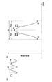
- A61B6/42—Arrangements for detecting radiation specially adapted for radiation diagnosis
- A61B6/4208—Arrangements for detecting radiation specially adapted for radiation diagnosis characterised by using a particular type of detector
- A61B6/4233—Arrangements for detecting radiation specially adapted for radiation diagnosis characterised by using a particular type of detector using matrix detectors
-
- G—PHYSICS
- G06—COMPUTING OR CALCULATING; COUNTING
- G06T—IMAGE DATA PROCESSING OR GENERATION, IN GENERAL
- G06T7/00—Image analysis
- G06T7/20—Analysis of motion
-
- A—HUMAN NECESSITIES
- A61—MEDICAL OR VETERINARY SCIENCE; HYGIENE
- A61B—DIAGNOSIS; SURGERY; IDENTIFICATION
- A61B6/00—Apparatus or devices for radiation diagnosis; Apparatus or devices for radiation diagnosis combined with radiation therapy equipment
- A61B6/48—Diagnostic techniques
- A61B6/486—Diagnostic techniques involving generating temporal series of image data
-
- A—HUMAN NECESSITIES
- A61—MEDICAL OR VETERINARY SCIENCE; HYGIENE
- A61B—DIAGNOSIS; SURGERY; IDENTIFICATION
- A61B6/00—Apparatus or devices for radiation diagnosis; Apparatus or devices for radiation diagnosis combined with radiation therapy equipment
- A61B6/50—Apparatus or devices for radiation diagnosis; Apparatus or devices for radiation diagnosis combined with radiation therapy equipment specially adapted for specific body parts; specially adapted for specific clinical applications
- A61B6/507—Apparatus or devices for radiation diagnosis; Apparatus or devices for radiation diagnosis combined with radiation therapy equipment specially adapted for specific body parts; specially adapted for specific clinical applications for determination of haemodynamic parameters, e.g. perfusion CT
-
- A—HUMAN NECESSITIES
- A61—MEDICAL OR VETERINARY SCIENCE; HYGIENE
- A61B—DIAGNOSIS; SURGERY; IDENTIFICATION
- A61B6/00—Apparatus or devices for radiation diagnosis; Apparatus or devices for radiation diagnosis combined with radiation therapy equipment
- A61B6/52—Devices using data or image processing specially adapted for radiation diagnosis
- A61B6/5258—Devices using data or image processing specially adapted for radiation diagnosis involving detection or reduction of artifacts or noise
- A61B6/5264—Devices using data or image processing specially adapted for radiation diagnosis involving detection or reduction of artifacts or noise due to motion
- A61B6/527—Devices using data or image processing specially adapted for radiation diagnosis involving detection or reduction of artifacts or noise due to motion using data from a motion artifact sensor
-
- G—PHYSICS
- G06—COMPUTING OR CALCULATING; COUNTING
- G06T—IMAGE DATA PROCESSING OR GENERATION, IN GENERAL
- G06T2207/00—Indexing scheme for image analysis or image enhancement
- G06T2207/10—Image acquisition modality
- G06T2207/10116—X-ray image
-
- G—PHYSICS
- G06—COMPUTING OR CALCULATING; COUNTING
- G06T—IMAGE DATA PROCESSING OR GENERATION, IN GENERAL
- G06T2207/00—Indexing scheme for image analysis or image enhancement
- G06T2207/20—Special algorithmic details
- G06T2207/20076—Probabilistic image processing
-
- G—PHYSICS
- G06—COMPUTING OR CALCULATING; COUNTING
- G06T—IMAGE DATA PROCESSING OR GENERATION, IN GENERAL
- G06T2207/00—Indexing scheme for image analysis or image enhancement
- G06T2207/30—Subject of image; Context of image processing
- G06T2207/30004—Biomedical image processing
- G06T2207/30061—Lung
-
- G—PHYSICS
- G06—COMPUTING OR CALCULATING; COUNTING
- G06T—IMAGE DATA PROCESSING OR GENERATION, IN GENERAL
- G06T2207/00—Indexing scheme for image analysis or image enhancement
- G06T2207/30—Subject of image; Context of image processing
- G06T2207/30004—Biomedical image processing
- G06T2207/30101—Blood vessel; Artery; Vein; Vascular
- G06T2207/30104—Vascular flow; Blood flow; Perfusion
Definitions
- the present invention relates to an image processing technique for a dynamic image in which a human or animal body is photographed.
- Patent Document 2 discloses a technique for detecting a current phase in a subject's breathing cycle and controlling an X-ray source in accordance with the current phase.
- a difference image between temporally adjacent images is calculated using a plurality of X-ray moving images acquired continuously in time series, and corresponding pixel groups in the plurality of difference images are calculated.
- a technique for generating a single image composed of pixels each having a maximum pixel value is disclosed.
- the pixel value of the lung field in the chest X-ray moving image is changed by the heartbeat property, and the change information of the pixel value is regarded as the pulmonary blood flow information. It is a technology that is effectively used for the diagnosis of embolism and heart disease. As a specific method, it recognizes the cardiac dynamics in the ventricular diastole and increases blood flow from the heart to the lungs in the ventricular systole (pulmonary blood flow). A technique for generating information on changes in pixel values of a chest X-ray moving image accompanying an increase in the number of chest X-ray images is disclosed.
- Patent Document 2 it is possible to maximize the amount of information necessary for dynamic diagnosis by controlling the X-ray source according to the respiratory cycle.
- the purpose is to examine movement, and it is not intended for blood flow analysis and is not disclosed.
- the present invention has been made in view of the above-described first situation, and is an image that has high accuracy, can obtain an appropriate blood flow analysis value, and can prevent deterioration in thrombus discrimination performance due to dynamic diagnosis.
- the purpose is to provide processing technology.
- the present invention has been made in view of the above-mentioned second situation, and it is possible to obtain a highly accurate blood flow analysis value in consideration of the respiratory phase state (inspiratory phase state and expiratory phase state).
- An object is to provide an image processing technique.
- an image processing apparatus for performing blood flow analysis, wherein a human body or an animal body Synchronized with the moving image acquisition means for acquiring a moving image composed of a plurality of frame images sequentially captured in the time direction of the state in which the blood flow of the target region in the inside changes in synchronization with the time at which the frame image was captured Respiration information acquisition means for performing respiration information acquisition processing for acquiring respiration information in the body, and a blood flow suppression time indicating a time at which blood flow in the target region is expected to be suppressed with respiration are used as the respiration information.
- a blood flow suppression time determination means for performing a blood flow suppression time determination process to be determined based on the blood flow analysis time, excluding the frame image taken at the blood flow suppression time from the subject of blood flow analysis or compared to other time zones
- a blood flow analysis correcting means for performing blood analysis contents correction process for decreasing the analysis importance, the.
- Moving image acquisition means for acquiring a moving image composed of a plurality of frame images sequentially photographed in the time direction, and respiratory information acquisition for acquiring respiration information in the body synchronized with the photographing time at which the frame image was photographed
- Respiration information acquisition means for performing processing
- phase state determination means for performing phase state determination processing for determining whether the respiration information belongs to an inhalation phase state or an expiration phase state and obtaining a phase state determination result
- Analysis for setting a blood flow analysis range in at least one of the inspiration phase state and the expiration phase state based on the respiratory information and the phase state determination result
- Blood flow analysis value calculation for obtaining a blood flow analysis value in the at least one state by performing blood flow analysis on an analysis range setting means for performing surrounding setting processing and the frame image in the blood flow analysis range
- a blood flow analysis value calculation unit that performs processing.
- the blood flow suppression time determination unit sets the blood flow suppression time based on the respiratory information
- the blood flow analysis correction unit captures the blood flow suppression time.
- the blood flow analysis content correction processing is performed to exclude the frame image from the blood flow analysis target or to lower the importance of blood flow analysis compared to other time zones. Therefore, blood flow analysis with blood flow analysis content correction processing becomes possible, and it is possible to avoid abnormal blood flow analysis values due to respiration. A value can be obtained. For this reason, it is possible to prevent the thrombus discrimination performance from being lowered, and to perform the blood flow dynamic diagnosis appropriately and efficiently.
- the blood flow analysis range in at least one of the inspiration phase state and the expiration phase state is set based on the respiration information and the phase state determination result,
- the blood flow analysis value in the at least one state is obtained by performing the blood flow analysis on the frame image. Accordingly, it is possible to obtain a blood flow analysis value corresponding to at least one of the inspiratory phase state and the expiratory phase state desired by the user, that is, taking into consideration the respiratory phase state. For this reason, blood flow image diagnosis can be performed appropriately and efficiently.
- FIG. 1 is a diagram illustrating an overall configuration of a radiation dynamic image capturing system 100 according to a first embodiment. It is a figure explaining a respiratory phase. It is a block diagram which shows the function structure of the image processing apparatus 3 which concerns on 1st Embodiment. It is a figure which illustrates the dynamic image image
- the radiation dynamic image capturing system captures a radiation image in a situation in which the physical state of a target region of a subject periodically changes over time using a human or animal body as a subject.
- FIG. 1 is a diagram showing an overall configuration of a radiation dynamic image capturing system according to the first embodiment.
- the radiation dynamic image capturing system 100 includes an image capturing device 1, an image capturing control device 2 (imaging console), and an image processing device 3 (diagnosis console).
- the imaging device 1 and the imaging control device 2 are connected by a communication cable or the like, and the imaging control device 2 and the image processing device 3 are connected via a communication network NT such as a LAN (Local Area Network).
- NT such as a LAN (Local Area Network).
- Each device constituting the radiation dynamic image capturing system 100 conforms to the DICOM (Digital Image and Communication Communications in Medicine) standard, and communication between the devices is performed according to the DICOM standard.
- DICOM Digital Image and Communication Communications in Medicine
- the imaging device 1 is configured by, for example, an X-ray imaging device or the like, and is an apparatus that captures the dynamics of the chest of the subject M accompanied by respiratory motion. Dynamic imaging is performed by acquiring a plurality of images sequentially in time while repeatedly irradiating the chest of the subject M with radiation such as X-rays. A series of images obtained by this continuous shooting is called a dynamic image (moving image). Each of the plurality of images constituting the dynamic image is called a frame image. In the present embodiment, blood flow analysis is performed based on these images, and a respiration waveform (respiration phase) is obtained.
- a respiration waveform respiration waveform
- the imaging apparatus 1 includes an irradiation unit (radiation source) 11, a radiation irradiation control device 12, an imaging unit (radiation detection unit) 13, a reading control device 14, a cycle detection sensor 15, The cycle detection device 16 is provided.
- the irradiation unit 11 irradiates the subject M with radiation (X-rays) according to the control of the radiation irradiation control device 12.
- the illustrated example is a system for the human body, and the subject M corresponds to the person to be inspected.
- the subject M is also referred to as a “subject”.
- the radiation irradiation control device 12 is connected to the imaging control device 2 and performs radiation imaging by controlling the irradiation unit 11 based on the radiation irradiation conditions input from the imaging control device 2.
- the imaging unit 13 is configured by a semiconductor image sensor such as an FPD, and converts the radiation irradiated from the irradiation unit 11 and transmitted through the subject M into an electrical signal (image information).
- a semiconductor image sensor such as an FPD
- the reading control device 14 is connected to the photographing control device 2.
- the reading control device 14 controls the switching unit of each pixel of the imaging unit 13 based on the image reading condition input from the imaging control device 2, and switches the reading of the electric signal accumulated in each pixel.
- the image data is acquired by reading the electrical signal accumulated in the imaging unit 13.
- the reading control device 14 outputs the acquired image data (frame image) to the imaging control device 2.
- the image reading conditions are, for example, a frame rate, a frame interval, a pixel size, an image size (matrix size), and the like.
- the frame rate is the number of frame images acquired per second and matches the pulse rate.
- the frame interval is the time from the start of one frame image acquisition operation to the start of the next frame image acquisition operation in continuous shooting, and coincides with the pulse interval.
- the radiation irradiation control device 12 and the reading control device 14 are connected to each other, and exchange synchronization signals with each other to synchronize the radiation irradiation operation and the image reading operation.
- the cycle detection device 16 detects the respiratory cycle of the subject M and outputs cycle information to the control unit 21 of the imaging control device 2.
- the cycle detection device 16 also measures and controls the cycle detection sensor 15 that detects the movement of the chest of the subject M (respiration cycle of the subject M) by laser irradiation and the time of the respiratory cycle detected by the cycle detection sensor 15.
- a timing unit (not shown) that outputs to the unit 21.
- the imaging control device 2 outputs radiation irradiation conditions and image reading conditions to the imaging device 1 to control radiation imaging and radiographic image reading operations by the imaging device 1, and also captures dynamic images acquired by the imaging device 1. Displayed for confirmation of whether the image is suitable for confirmation of positioning or diagnosis.
- the photographing control device 2 includes a control unit 21, a storage unit 22, an operation unit 23, a display unit 24, and a communication unit 25, and each unit is connected by a bus 26. ing.
- the control unit 21 includes a CPU (Central Processing Unit), a RAM (Random Access Memory), and the like.
- the CPU of the control unit 21 reads the system program and various processing programs stored in the storage unit 22 in accordance with the operation of the operation unit 23, expands them in the RAM, and performs shooting control processing described later according to the expanded programs.
- Various processes including the beginning are executed to centrally control the operation of each part of the imaging control device 2 and the operation of the imaging device 1.
- the storage unit 22 is configured by a nonvolatile semiconductor memory, a hard disk, or the like.
- the storage unit 22 stores various programs executed by the control unit 21 and data such as parameters necessary for execution of processing by the programs or processing results.
- the operation unit 23 includes a keyboard having cursor keys, numeric input keys, various function keys, and the like, and a pointing device such as a mouse.
- the operation unit 23 is input via a keyboard key operation, a mouse operation, or a touch panel.
- the indicated instruction signal is output to the control unit 21.
- the display unit 24 is configured by a monitor such as a color LCD (Liquid Crystal Display), and displays an input instruction, data, and the like from the operation unit 23 in accordance with an instruction of a display signal input from the control unit 21.
- a monitor such as a color LCD (Liquid Crystal Display)
- LCD Liquid Crystal Display
- the communication unit 25 includes a LAN adapter, a modem, a TA (Terminal Adapter), and the like, and controls data transmission / reception with each device connected to the communication network NT.
- the image processing device 3 acquires the dynamic image transmitted from the imaging device 1 via the imaging control device 2 and displays an image for a doctor or the like to perform an interpretation diagnosis.
- the image processing apparatus 3 includes a control unit 31, a storage unit 32, an operation unit 33, a display unit 34, a communication unit 35, and an analysis unit 36. They are connected by a bus 37.
- the control unit 31 includes a CPU, a RAM, and the like.
- the CPU of the control unit 31 reads the system program and various processing programs stored in the storage unit 32 in accordance with the operation of the operation unit 33, expands them in the RAM, and executes various processes according to the expanded programs.
- the operation of each part of the image processing apparatus 3 is centrally controlled (details will be described later).
- the storage unit 32 is configured by a nonvolatile semiconductor memory, a hard disk, or the like.
- the storage unit 32 stores various programs executed by the control unit 31 and data such as parameters necessary for execution of processing by the programs or processing results.
- the storage unit 32 stores an image processing program for executing image processing to be described later.
- These various programs are stored in the form of readable program codes, and the control unit 31 sequentially executes operations according to the program codes.
- the operation unit 33 includes a keyboard having cursor keys, numeric input keys, various function keys, and the like, and a pointing device such as a mouse.
- the operation unit 33 is input via a keyboard key operation, a mouse operation, or a touch panel.
- the instruction signal is output to the control unit 31.
- the display unit 34 is composed of a monitor such as a color LCD, and displays an input instruction from the operation unit 33, data, and a display image to be described later in accordance with an instruction of a display signal input from the control unit 31.
- the communication unit 35 includes a LAN adapter, a modem, a TA, and the like, and controls data transmission / reception with each device connected to the communication network NT.
- the analysis unit 36 analyzes the blood flow based on the dynamic image transmitted from the imaging device 1 under the control of the control unit 31.
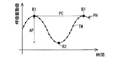
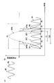
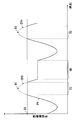
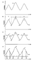
- FIG. 2 is a diagram illustrating a general characteristic of the respiratory phase, in which FIG. 2 (a) shows a part of the waveform of the respiratory phase, and FIG. 2 (b) is an area AR (one cycle) in FIG. 2 (a). Respiratory phase in minutes).
- the horizontal axis indicates the time (time direction) when the moving image was taken, and the vertical axis indicates a respiratory vibration value (described later in detail).
- the respiratory phase PH for one cycle PC has a maximum inspiration phase B1 and a maximum expiration phase B2 (details will be described later). From the maximum expiration phase B2 to the maximum inspiration phase B1 Is referred to as the inspiratory phase PH1, and from the maximum inspiratory phase B1 to the maximum expiratory phase B2 is referred to as the expiratory phase PH2. That is, if the first half period PC1 of one period PC is the inhalation phase PH1 and the second half period PC2 is the expiration phase PH2, the first half period PC1 and the second half period PC2 are generally equal to each other for a healthy person.
- the blood flow analysis value obtained by the blood flow analysis is reduced from the original value at the time of the maximum inspiration phase B1. Normal value may not be obtained.
- time does not necessarily indicate a specific hour and minute, but the term “time” is used for convenience in order to express a predetermined timing or moment. .
- time is used as an expression including a specific moment in the elapsed time from the start of measurement, a specific timing in the elapsed time measured starting from a predetermined timing on the time axis, and the like.
- the image processing device 3 of the radiation dynamic imaging system 100 according to the first embodiment of the present invention obtains a blood flow analysis value in consideration of the time (timing) at which the blood flow is suppressed, thereby performing blood flow dynamic diagnosis. It becomes possible to carry out appropriately and efficiently.
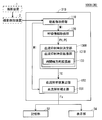
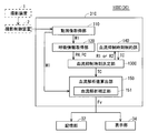
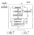
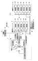
- FIG. 3 is a diagram illustrating a functional configuration realized by the control unit 31 when the CPU or the like operates according to various programs in the image processing apparatus 3 in the radiation dynamic image capturing system 100 together with other configurations. Note that the image processing apparatus 3 of this embodiment uses a dynamic image in which the chest including the heart and both lungs is mainly captured.
- the control unit 31 mainly includes a moving image acquisition unit 110, a respiration information acquisition unit 120, a blood flow suppression time determination unit 130, a blood flow analysis value calculation unit 150, and a blood flow analysis correction unit 151. Is done.
- control unit 31 As shown in FIG. 3 will be described as being realized by executing a preinstalled program, but it may be realized with a dedicated hardware configuration. .
- Moving Image Acquisition Unit 110 In the moving image acquisition unit 110, the state in which the blood flow in the target region in the body of the subject M captured by the reading control device 14 of the imaging device 1 is changed from a plurality of frame images sequentially captured in the time direction. Acquires the composed moving image.
- the target region in the present embodiment is a region to be subjected to blood flow analysis, and assumes a blood vessel region in the lung field region. That is, as shown in FIG. 3, the imaging control device 2 is interposed between the imaging device 1 and the image processing device 3, and the detection data (a plurality of frame images) stored in the storage unit 22 of the imaging control device 2. ) Is output to the communication unit 35 of the image processing apparatus 3 via the communication unit 25.
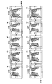
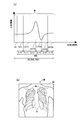
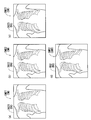
- FIG. 4 is a diagram exemplifying a moving image captured by radiodynamic image capturing with respect to the dynamics of the chest of the subject M accompanying respiration.
- the frame images M1 to M10 acquired by the moving image acquisition unit 110 are obtained by continuously capturing one period of the respiratory cycle at a constant imaging timing.
- blood flow in the chest of the subject M is analyzed using the frame images M1 to M10 (MI) shown in FIG. 4, and information about the breathing of the subject M is based on the frame image MI. Can also be sought.
- MI frame images M1 to M10
- Respiratory information acquisition unit 120 performs a respiratory information acquisition process for acquiring respiratory information in the subject M synchronized with the time when the frame image MI was captured.
- the respiratory information acquisition process is roughly divided into two processes.
- the first respiratory information acquisition process is a process of acquiring a respiratory vibration value indicated as a physical change value of the lung field region of the subject M as respiratory information.
- the respiratory vibration value here can be obtained based on, for example, a plurality of frame images MI constituting the moving image acquired by the moving image acquisition unit 110.
- the respiration information acquisition unit 120 calculates a respiratory vibration value using the plurality of frame images MI acquired by the moving image acquisition unit 110.
- the respiratory vibration value is an index corresponding to a change in the size of the lung field region due to respiration.
- the respiratory vibration value is “the area value of the lung field” and “the distance between the feature points of the lung field” will be described as an example.
- the respiratory vibration value is the “area value of the lung field”
- FIG. 5 is a schematic diagram illustrating the contour extraction of the lung field.
- the lung field can be extracted as right and left (see FIG. 5 (a)) or as an outline including the heart and spine regions (see FIG. 5 (b)). May be.
- conventional techniques for example, “Image feature analysis and computer-aided diagnosis: Accurate determination of ribcage boundary in chest radiographs”, Xin-Wei Xu and Kunio Doi, Medical Physics, Volume 22 (1995), May pp.617-626 etc.
- image feature analysis and computer-aided diagnosis Accurate determination of ribcage boundary in chest radiographs”
- Xin-Wei Xu and Kunio Doi Medical Physics, Volume 22 (1995), May pp.617-626 etc.
- the respiratory information acquisition unit 120 extracts the lung field outline OL using the acquired plurality of frame images MI, and calculates the number of pixels in the extracted area as the area value of the lung field part.
- the respiratory vibration value is acquired by detecting. Then, the change in the respiratory vibration value is set as the respiratory phase PH, and the respiratory cycle PC is detected (see FIG. 7 described later).
- the distance between feature points in the lung field is calculated using a plurality of frame images MI. That is, the lung field is extracted in the same manner as described above, and two feature points are obtained from the extracted region, and the distance between the two points is obtained as a respiratory vibration value.
- a change in the distance between the feature points (respiration vibration value) is defined as a respiration phase PH.
- FIG. 6 is a diagram illustrating the positions of feature points in the lung field region when the lung field contour OL in FIG. 5A is employed.
- the lung apex is the upper end LT of the lung region, and from the lung apex to the body axis direction.
- FIG. 6B shows an example in which the intersection of the lowered straight line and the diaphragm is extracted as the lower end LB of the lung region.
- the lung apex is extracted as the upper end LT of the lung region, and the lateral angle is extracted as the lower end LB of the lung region. This is an example.
- the respiration information acquisition unit 120 extracts the contour OL of the lung field region using the acquired plurality of frame images MI, and detects the distance between feature points from the extracted region. Get the vibration value. Then, the change in the respiratory vibration value is set as the respiratory phase PH, and the respiratory cycle PC is detected (see FIG. 7 described later).
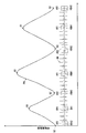
- FIG. 7 is a schematic diagram of the respiratory phase PH showing, in time series, waveform data of respiratory vibration values detected by the respiratory information acquisition unit 120, and respiratory vibration values such as area values of lung field regions, distances between feature points, and the like. Is calculated and monitored in the time direction for each photographing timing TM. 7 indicates the amplitude direction AP of the respiratory phase PH.
- one cycle of the breathing cycle (breathing cycle) PC is composed of inspiration and expiration, and consists of one expiration and one inspiration.
- inspiration cycle the area of the lung field in the thorax increases as the diaphragm lowers and breathes in.
- the maximum inspiration phase B1 is when the inspiration is taken in (maximum inspiration and expiration conversion point).
- expiration the region of the lung field becomes smaller as the diaphragm rises and exhales, but the maximum exhalation phase B2 is when exhaled to the maximum (conversion point of exhalation and inspiration).
- a method of measuring the respiratory vibration value with another device may be adopted.
- an apparatus as described in Japanese Patent No. 3793102 can be used.
- a method implemented by monitoring with a sensor composed of a laser beam and a CCD camera for example, “Study on sleep monitoring of sleepers using FG visual sensor", Hiroki Aoki, Masato Nakajima, IEICE Society Conference Proceedings of the Lectures 2001. Information and Systems Society Conference Proceedings, 320-321, 2001-08-29, etc.
- a sensor composed of a laser beam and a CCD camera for example, "Study on sleep monitoring of sleepers using FG visual sensor", Hiroki Aoki, Masato Nakajima, IEICE Society Conference Proceedings of the Lectures 2001. Information and Systems Society Conference Proceedings, 320-321, 2001-08-29, etc.
- the cycle detection sensor 15 of the cycle detection device 16 can be used. Further, as another method for detecting the respiratory vibration value, there are a method of detecting the movement of the chest of the subject using a respiratory monitor belt, and a method of detecting a respiratory airflow using an anemometer. It is also possible to apply.
- the second respiration information acquisition process is a process for acquiring, as respiration information, a respiration relative value indicating a relative value with which it can be determined whether the subject M belongs to the inspiratory phase PH1 or the expiratory phase PH2, regardless of the moving image. It is.
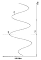
- FIG. 33 is a diagram illustrating the respiratory relative value.
- the horizontal axis indicates the time when the moving image was taken, and the vertical axis indicates the respiratory relative value.
- the respiratory relative value shows a positive value, it corresponds to the inspiration phase PH1
- the respiratory relative value shows a negative value
- the boundary where the respiratory relative value changes from the inhalation phase PH1 to the expiration phase PH2 corresponds to the maximum inspiration phase B1
- the boundary where the respiration relative value changes from the expiration phase PH2 to the inspiration phase PH1 corresponds to the maximum expiration phase B2.
- the example of the relative respiratory value is described. Actually, even if the relative respiratory value is not a plus or minus value, it can be determined whether it belongs to the inspiratory phase PH1 or the expiratory phase PH2 relatively. Any value can be used.
- the respiration relative value can be obtained from the measurement result by another device.
- a positive value is output
- a negative value is output.
- respiratory information is acquired from the outside in synchronism with moving image shooting of a plurality of frame images MI, and the respiratory cycle PC can be recognized from the respiratory relative value.
- the respiratory information acquisition unit 120 acquires a plurality of frame images MI through the moving image acquisition unit 110, acquires a respiratory relative value synchronized with the frame image MI, and respires based on the respiratory relative value.
- the period PC is detected (see FIG. 3).
- the blood flow suppression time determination unit 130 determines the blood flow suppression time indicating the time or timing at which the blood flow in the target region is supposed to be suppressed with breathing based on the respiratory information. (See FIG. 3).
- the first blood flow suppression time determination process is a process of setting the time at which the respiratory vibration value becomes the maximum value as the blood flow suppression time.
- FIG. 8 is a diagram for explaining the first blood flow suppression time determination process, where the vertical axis indicates the respiratory vibration value, and the horizontal axis indicates the time when the moving image was taken.
- the blood flow suppression time determination unit 130 sets the time corresponding to the maximum value MX among the respiratory vibration values obtained from the plurality of frame images MI to be subjected to dynamic diagnosis, to the blood flow suppression time. Set as TC11 (TC).
- Second Blood Flow Suppression Time Determination Process Maximum Inspiration Phase>
- the respiratory cycle PC can be recognized from the respiratory vibration value (see FIG. 2)
- the time at which the respiratory vibration value becomes the maximum value is determined for each respiratory cycle PC.
- Processing for setting the flow suppression time TC or (ii) Since the respiratory cycle PC can be recognized from the respiratory relative value (see FIG. 33), the respiratory relative value is changed from the inspiration phase PH1 to the expiration phase PH2 for each respiratory cycle PC. This is a process of setting the time when the blood flow changes to the blood flow suppression time TC.
- the first method is a method in which the time at which the respiratory vibration value reaches the maximum value in the entire time is sequentially set as the blood flow suppression time TC. Specifically, this is a method of extracting the maximum value (maximum inspiration phase B1) of the respiratory vibration value in a state where the respiratory vibration value in the entire time is smoothed and the high frequency noise component is reduced. Thereby, it becomes possible to prevent erroneous detection of the noise component included in the respiratory vibration value as a maximum value.
- the second method is a method of setting the time at which the respiratory vibration value becomes the maximum value for each respiratory cycle PC as the blood flow suppression time TC.
- the difference from the first method is that the maximum value of the respiratory vibration value (that is, the maximum inspiration phase B1) is extracted not in the entire time but in the respiratory cycle PC.
- the maximum value may be extracted while smoothing the respiratory vibration value and reducing the high frequency noise component.
- FIG. 9 is a diagram for explaining the process (i) in the second blood flow suppression time determination process, in which the vertical axis indicates the respiratory vibration value and the horizontal axis indicates the time when the moving image was taken.
- the blood flow suppression time determination unit 130 calculates the respiratory vibration values obtained from all the frame images MI that are the targets of the dynamic diagnosis. The time at which the maximum value is reached is sequentially set as the blood flow suppression time TC12 (TC).
- the blood flow suppression time determination unit 130 calculates a respiratory vibration value for each respiratory cycle PC among respiratory vibration values obtained from a plurality of frame images MI to be subjected to dynamic diagnosis.
- the maximum value that is, the maximum inspiration phase B1 is extracted, and the time when the maximum inspiration phase B1 is reached is set as the blood flow suppression time TC12 (TC) for each respiratory cycle PC.
- the blood flow suppression time determination unit 130 determines that the respiratory relative value is the inspiration phase PH1.
- the expiration phase PH2 that is, the maximum inspiration phase B1 within each respiratory cycle PC
- TC blood flow suppression time
- the maximum inspiration phase B1 since the maximum inspiration phase B1 is detected based on the change in the respiration phase, the maximum inspiration phase B1 can be detected relatively easily.
- the third blood flow suppression time determination process is a process of determining, as the blood flow suppression time TC, a time included in a time zone in which the respiratory vibration value is equal to or greater than a predetermined reference value.
- FIG. 10 is a diagram for explaining the third blood flow suppression time determination process, where the vertical axis indicates the respiratory vibration value, and the horizontal axis indicates the time when the moving image was taken.
- the blood flow suppression time determination unit 130 uses a time zone in which respiratory vibration values obtained from a plurality of frame images MI to be subjected to dynamic diagnosis are equal to or greater than a predetermined reference value SV.
- TC13 flow suppression time
- a time zone corresponding to the respiratory phase EPH that is equal to or greater than the reference value SV in the respiratory phase PH is set as the blood flow suppression time TC13.
- a certain time zone (time included in) is set as the blood flow suppression time TC13.
- Blood flow analysis value calculation unit 150 obtains a blood flow analysis value for the analysis data to be subjected to blood flow analysis in the moving image acquired by the moving image acquisition unit 110. Perform analysis processing. Then, the blood flow analysis value Fv used for the dynamic diagnosis is output to the storage unit 32 and the display unit 34.
- the blood flow analysis value here is basically a value obtained by taking a difference between a plurality of frame images MI included in a moving image, but processing such as noise removal is also performed if necessary. Do.
- Blood flow analysis correction unit 151 In the blood flow analysis correction unit 151, the frame image MI taken at the blood flow suppression time TC set by the blood flow suppression time determination unit 130 is excluded from the blood flow analysis target or compared with other time zones. The blood flow analysis content correction process is performed to lower the blood flow.
- the blood flow analysis content correction processing here is either pre-processing performed before the blood flow analysis processing is performed or post-processing performed after the blood flow analysis processing is performed.
- preprocessing among the analysis data, for the data at the blood flow suppression time TC, (a1) the processing for prohibiting the blood flow analysis processing, and (a2) the blood with reduced importance.
- post-processing (a3) among the blood flow analysis values, for the data at the blood flow suppression time TC, as the blood flow analysis value, the flow analysis processing is executed. This is either processing that is not handled, or (a4) processing that reduces the importance of the blood flow analysis value.
- pre-processing and post-processing will be described separately.
- Pretreatment> As the pre-processing (a1), a process of removing data at the blood flow suppression time TC from the analysis data is performed. Then, after the blood flow analysis value calculation unit 150 obtains the blood flow analysis value Fv by performing blood flow analysis on data other than the blood flow suppression time TC, the blood flow analysis value Fv is displayed in the storage unit 32 or the display. To the unit 34.
- the blood flow analysis value reliability in order to reduce the importance and reduce the influence on the blood flow analysis value with respect to the data at the blood flow suppression time TC
- Weighting coefficient here refers to, for example, extracting a suspicious position or time as a thrombus based on a blood flow analysis value (hereinafter referred to as “f”) calculated in a normal blood flow analysis process (case 1).
- f blood flow analysis value
- the blood flow analysis value reliability w when it is low, the final thrombosis suspicion can be obtained by multiplying (w * B) so that the thrombosis suspicion decreases. Further, in case 2, it is possible to employ a method of multiplying the suspected blood clot degree for each patient by the blood flow analysis value reliability w.
- the accurate blood flow analysis value Fv for each blood flow cycle is obtained not by simply averaging the blood flow analysis value f of each blood flow cycle but by a weighted average using the blood flow analysis value reliability w. It becomes possible.
- the blood flow analysis value calculation unit 150 calculates the corrected blood flow analysis value Fv, and then outputs the blood flow analysis value Fv to the storage unit 32 and the display unit 34.
- the post-processing (a3) the data at the blood flow suppression time TC among the analyzed data (blood flow analysis value) calculated by the blood flow analysis value calculation unit 150 is used as the blood flow analysis value.
- a blood flow analysis value Fv a blood flow analysis value other than the blood flow suppression time TC is set as a blood flow analysis value Fv.
- the blood flow analysis correction unit 151 outputs the blood flow analysis value Fv to the storage unit 32 and the display unit 34.
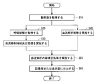
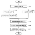
- FIG. 11 shows a flow when the blood flow analysis content correction processing is the preprocessing of the above (a1) or (a2), and in FIG. 12, the blood flow analysis content correction processing is the above (a3) or (a4).
- FIG. 11 shows a flow when the blood flow analysis content correction processing is the preprocessing of the above (a1) or (a2), and in FIG. 12, the blood flow analysis content correction processing is the above (a3) or (a4).
- This is a flow in the case of post-processing. Since the individual functions of each unit have already been described (see FIG. 3), only the overall flow will be described here.
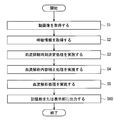
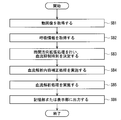
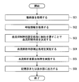
- step S ⁇ b> 1 the moving image acquisition unit 110 of the control unit 31 captures a moving image (a plurality of frame images MI) photographed by the reading control device 14 of the photographing device 1. Get through 2.
- step S2 the respiratory information acquisition unit 120 performs a first or second respiratory information acquisition process for acquiring respiratory information such as a respiratory vibration value or a respiratory relative value, and detects a respiratory phase PH and a respiratory cycle PC (FIG. 5 to 7).
- step S3 the blood flow suppression time determination unit 130 performs any one of the first to third blood flow suppression time determination processes, and sets the blood flow suppression time TC (any one of TC11, TC12, and TC13). (See FIGS. 8 to 10).
- step S4 the blood flow analysis contents that the blood flow analysis correction unit 151 excludes from the blood flow analysis target or lowers the importance of blood flow analysis compared to other time zones at the blood flow suppression time TC set in step S3.
- Perform correction processing That is, the blood flow analysis content correction process here is a pre-process performed before the blood flow analysis process is performed, and the blood flow analysis correction unit 151 performs the process (a1) or (a2). Do.
- step S5 the blood flow analysis value calculation unit 150 considers the result of the process (a1) or (a2) performed in step S4, and performs blood flow on the analysis data (a plurality of frame images MI). An analysis process is performed to obtain a blood flow analysis value Fv.
- step S6 the blood flow analysis value calculation unit 150 outputs the corrected blood flow analysis value Fv obtained in step S5 on the storage unit 32 or the display unit 34 (see FIG. 3). The flow is terminated.
- step S40 the blood flow analysis value calculation unit 150 performs blood flow analysis processing on the plurality of frame images MI acquired in step S10 to obtain blood flow analysis values.
- step S40 may be processed before step S20 and step S30, or may be processed after step S20 and step S30, in addition to the configuration processed in parallel with step S20 and step S30. That is, step S40 only needs to be processed before step S50.
- step S50 the blood flow analysis correcting unit 151 is excluded from the blood flow analysis target or in another time zone at the blood flow suppression time TC set in step S30 among the blood flow analysis values obtained in step S40.
- the blood flow analysis content correction process of either (a3) or (a4) described above that lowers the importance of blood flow analysis is performed.
- step S60 the blood flow analysis correction unit 151 outputs the corrected blood flow analysis value Fv obtained in step S50 to the storage unit 32 and the display unit 34.
- the blood flow suppression time determination unit 130 determines the blood flow suppression time TC based on the respiration information, and the blood flow analysis correction unit 151 captures the blood flow suppression time TC.
- the blood flow analysis content correction process is performed to exclude the frame image from the target for blood flow analysis or to lower the importance of blood flow analysis compared to other time zones. Therefore, blood flow analysis with blood flow analysis content correction processing becomes possible, and it is possible to avoid abnormal blood flow analysis values due to respiration.
- the value Fv can be obtained. For this reason, it is possible to prevent the thrombus discrimination performance from being lowered, and to perform the blood flow dynamic diagnosis appropriately and efficiently.
- the first blood flow suppression time determination process is a process of determining the time when the respiratory vibration value becomes the maximum value MX as the blood flow suppression time TC11. Thereby, it is possible to determine the time when blood flow is most suppressed and the blood flow analysis value is assumed to have the most adverse influence as the blood flow suppression time TC11.
- the second blood flow suppression time determination process is a process of determining, as the blood flow suppression time TC12, the time when the respiratory vibration value becomes the maximum value (maximum inspiration phase B1 within each of the respiratory cycles PC) for each respiratory cycle. is there. Since the maximum value is obtained for each respiratory cycle PC, based on the physical change value of the lung field region, it is possible to determine the time assumed to have an adverse effect on the blood flow analysis value as the blood flow suppression time TC12. It becomes.
- the second blood flow suppression time determination process is a time at which the respiratory relative value changes from the inspiration phase to the expiration phase for each respiratory cycle PC (the time when the maximum inspiration phase B1 in each respiratory cycle PC in FIG. 33).
- the respiratory cycle PC from the respiratory relative value, it is possible to simplify the respiratory information acquisition process because it is not necessary to acquire the respiratory cycle PC based on the moving image.
- the third blood flow suppression time determination process is a process of determining a time when the respiratory vibration value is greater than or equal to a predetermined reference value SV (included in the time zone) as the blood flow suppression time TC13. Accordingly, the blood flow suppression time TC13 can be easily expanded and set without obtaining the maximum inspiration phase B1 from the maximum value MX for each respiratory cycle PC.
- the difference in blood flow analysis value Fv can be accurately compared for moving image data in the same body (subject M) at different imaging times. It is possible to accurately observe the blood flow state.
- the blood flow analysis content correction process includes any one of the processes (a1) to (a4). That is, in the process of (a1) or (a2), the process is prohibited before the blood flow analysis process or the process of reducing the influence of the process is performed. It is possible to perform blood flow analysis. In particular, in the process (a1), it is not necessary to perform the blood flow analysis process at the blood flow suppression time TC, so that the calculation time can be shortened without performing unnecessary calculations.
- the processing at the blood flow suppression time TC after the blood flow analysis processing is performed or processing that is not handled as the blood flow analysis value, or the importance is reduced. Since the process is performed, it is not necessary to set the blood flow suppression time TC before the blood flow analysis process, and the blood flow suppression time TC can be set after the blood flow analysis process is performed.
- the target region is a blood vessel region in the lung field region
- FIG. 13 is a diagram showing a functional configuration of the control unit 31A used in the image processing apparatus 3A configured as the second embodiment of the present invention.
- the control unit 31A is used as an alternative to the control unit 31 (see FIG. 3) in the image processing apparatus 3 of the first embodiment.
- the difference from the first embodiment is that a blood flow suppression time determination unit 130A corresponding to the blood flow suppression time determination unit 130 of the first embodiment includes a blood flow suppression time expansion unit 131A, and the blood flow suppression time expansion unit 131A It is a point provided with the amplitude direction expansion part 132.
- the remaining configuration is the same as that of the image processing apparatus 3.
- the blood flow suppression time determination unit 130A includes a blood flow suppression time expansion unit 131A that extends the blood flow suppression time TC so as to have a time width ⁇ T with reference to the blood flow suppression time TC. Further, the blood flow suppression time expansion unit 131A includes an amplitude direction expansion unit 132 that performs an amplitude direction expansion process so as to set the time width ⁇ T.
- ⁇ Amplitude direction expansion processing can be broadly divided into four processes, one of which is performed.
- the first to fourth time axis direction expansion processes will be described separately.
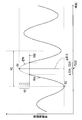
- First Amplitude Direction Expansion Processing a value that is smaller by a first value than a value at which the respiratory vibration value is maximum is set as a first threshold, and a time width is set according to a time at which the respiratory vibration value is equal to or greater than the first threshold. It is a process to set.
- FIG. 14 is a diagram for explaining the first amplitude direction expansion processing, where the vertical axis indicates the respiratory vibration value, and the horizontal axis indicates the time when the moving image was captured.
- the blood flow suppression time TC11 is set so that the blood flow suppression time expansion unit 131A has a time width ⁇ T21 with reference to the blood flow suppression time TC11 set in the first blood flow suppression time determination process.
- a value that is less than the maximum value MX of the respiratory vibration value by the first value V1 is set as the first threshold value TH1, and the time width is determined by the time in the respiratory phase EPH at which the respiratory vibration value is equal to or greater than the first threshold value TH1.
- ⁇ T21 is set.
- assembly of the time which exists in time width (DELTA) T21 is made into blood flow suppression time TC21.
- First value determination process In the first value determination process, the first value V1 using the first amplitude direction expansion process is based on a difference value between (b1) the value MX at which the respiratory vibration value is maximized and the value MN at which it is minimized.
- the first threshold value TH1 is set by setting any one of the calculated value and (b2) a predetermined constant value.
- FIG. 16 is a diagram for explaining the first value determination process, in which the vertical axis represents the respiratory vibration value, and the horizontal axis represents the time when the moving image was taken.
- the blood flow suppression time TC11 is set so that the blood flow suppression time expansion unit 131A has a time width ⁇ T23 with reference to the blood flow suppression time TC11 set in the first blood flow suppression time determination process. To expand.
- FIG. 16 describes the method (b1) in the first value determination process. That is, this is a method of determining the first value V1 as an arbitrary ratio with respect to the difference value ⁇ MXN between the maximum value MX and the minimum value MN of the respiratory vibration values. For example, when the first value V1 is set to a value of 20% in terms of percentage with respect to the difference value ⁇ MXN, and when set to a value of 40%, the first threshold value TH1 is 40% than when the value is 20%. Therefore, the time width ⁇ T23 is set wider at 40% than at 20%.
- the blood flow suppression time TC23 also varies according to the variation of the time width ⁇ T23 according to an arbitrary ratio.
- the first value V1 is set to a predetermined value, and thus the blood flow suppression time TC23 varies according to the fixed value designated by the user.
- the first value V1 is determined using the method (b1) or (b2) described above, but is not limited to these methods, and may be determined using another method.
- the first value V1 may be determined in consideration of the patient's profile such as the size of the patient's physique and health status (whether or not the patient has COPD (chronic obstructive pulmonary disease)).
- Second Amplitude Direction Expansion Processing for each respiratory cycle PC, a value that is smaller by a second value than the value B1 at which the respiratory vibration value is maximized is set as the second threshold, and the respiratory vibration value is equal to or greater than the second threshold. This is a process for setting the time width according to the time.
- FIG. 15 is a diagram for explaining the second amplitude direction expansion processing, where the vertical axis indicates the respiratory vibration value, and the horizontal axis indicates the time when the moving image was captured.
- the blood flow suppression time TC12 is set so that the blood flow suppression time expansion unit 131A has a time width ⁇ T22 with reference to the blood flow suppression time TC12 set in the second blood flow suppression time determination process. To expand.
- a value that is smaller by a second value V2 than the value at which the respiratory vibration value becomes maximum (that is, the maximum inspiration phase B1) is set as the second threshold value TH2, and the respiratory vibration value is
- the time width ⁇ T22 is set according to the time in the respiratory phase EPH that is equal to or greater than the threshold value TH2.
- assembly of the time which exists in time width (DELTA) T22 is made into blood flow suppression time TC22.
- Second value determination process In the second value determination process, the second value is set for each (c1) respiratory cycle PC, and is calculated based on the difference value between the value B1 at which the respiratory vibration value is maximized and the value B2 at which it is minimized.
- (C2) is a process of setting the second threshold value TH2 by taking any one of predetermined values.
- FIG. 17 is a diagram for explaining the second value determination process, in which the vertical axis indicates the respiratory vibration value, and the horizontal axis indicates the time at which the moving image was taken.
- the blood flow suppression time TC12 is provided so that the blood flow suppression time expansion unit 131A has a time width ⁇ T24 with reference to the blood flow suppression time TC12 set in the second blood flow suppression time determination process. To expand.
- the method (c1) in the second value determination process will be described by showing only one respiratory cycle PC. That is, the second value V2 is set for each respiratory cycle PC, and the respiratory vibration value is arbitrary with respect to the difference value ⁇ B12 between the maximum value (that is, the maximum inspiration phase B1) and the minimum value (that is, the maximum expiration phase B2). It is a method of determining as a ratio. For example, in the case where the second value V2 is set to a value of 20% in terms of the difference value ⁇ B12 and to the value of 40%, the second threshold TH2 is set to 20% in the same manner as described above. Therefore, the time width ⁇ T24 is set wider at 40% than at 20%.
- the blood flow suppression time TC24 also varies as the time width ⁇ T24 varies according to an arbitrary ratio.
- the second value V2 is set to a predetermined value, so that the blood flow suppression time TC24 varies according to the fixed value designated by the user.
- the second value V2 is determined using the above methods (c1) and (c2), but is not limited to these methods, and may be determined using other methods.
- the user may specify the desired value and determine the second value V2, or determine the second value V2 in consideration of the patient profile as described above. Also good.
- FIG. 18 is a diagram illustrating an operation flow of the image processing apparatus 3A according to the second embodiment.
- FIG. 18 representatively shows the case where the blood flow analysis content correction processing is the preprocessing of (a1) or (a2).
- steps SA1, SA2, SA4 to SA6 are the same as steps S1, S2, S4 to S6 in FIG.
- the blood flow suppression time determination unit 130A performs the first or second blood flow suppression in step SA3.
- the amplitude direction expansion unit 132 sets the time width ⁇ T by one of the first and second amplitude direction expansion processes and determines the blood flow suppression time TC. (See FIGS. 14 to 17).
- the amplitude direction expansion unit 132 sets the time width ⁇ T21 or ⁇ T23 by the first amplitude direction expansion process.
- the blood flow suppression time TC21 or TC23 is set (see FIGS. 14 and 16).
- the amplitude direction expansion unit 132 sets the time width ⁇ T22 or ⁇ T24 by the second amplitude direction expansion process, and blood The flow suppression time TC22 or TC24 is set (see FIGS. 15 and 17).
- the blood flow suppression time determination unit 130A sets the blood flow suppression time TC11 or TC12 so as to have the time width ⁇ T with reference to the blood flow suppression time TC11 or TC12.
- a blood flow suppression time expansion unit 131A for expansion is provided.
- the first amplitude direction expansion process generates the time width ⁇ T21 according to the time when the respiratory vibration value becomes equal to or greater than the first threshold value TH1, thereby more reliably extracting the time zone in which the suspected blood flow suppression is high.
- the blood flow suppression time TC21 can be set (see FIG. 14).
- the second amplitude direction expansion process sets the time width ⁇ T22 using a value (maximum inspiration phase B1) that maximizes the respiratory vibration value for each respiratory cycle PC, thereby suppressing blood flow within the respiratory cycle PC. It is possible to appropriately extract the time when the suspicion is high and set it as the blood flow suppression time TC22. In addition, since the amplitude direction expansion processing is performed for each respiratory cycle PC, the effect of robustness that is not affected by other cycles is achieved (see FIG. 15).
- the first threshold value TH1 can be appropriately set without being too low (see FIG. 16).
- the first threshold value TH1 can be easily set without specifically calculating the maximum respiratory amplitude value within the respiratory phase PH. Become.
- the second value V2 in the second amplitude direction expansion processing the difference between the value (maximum inspiration phase B1) that maximizes the respiratory vibration value for each respiratory cycle PC and the value (maximum expiration phase B2) that minimizes
- the second value V2 can be determined based on the respiratory amplitude value, so that the second threshold value TH2 can be appropriately set without being too low (see FIG. 17).
- a predetermined constant value is used as the second value V2
- FIG. 19 is a diagram illustrating a functional configuration of the control unit 31B used in the image processing apparatus 3B configured as the third embodiment of the present invention.
- the control unit 31B is used as an alternative to the control unit 31 (see FIG. 3) in the image processing apparatus 3 of the first embodiment.
- the difference from the first embodiment is that a blood flow suppression time determination unit 130B corresponding to the blood flow suppression time determination unit 130 of the first embodiment includes a blood flow suppression time expansion unit 131B, and the blood flow suppression time expansion unit 131B It is a point provided with the time-axis direction expansion part 133.
- the remaining configuration is the same as that of the image processing apparatus 3.
- the blood flow suppression time determination unit 130B includes a blood flow suppression time expansion unit 131B that extends the blood flow suppression time TC so as to have a time width ⁇ T with reference to the blood flow suppression time TC.
- the blood flow suppression time expansion unit 131B includes a time axis direction expansion unit 133 that performs a time axis direction expansion process so as to set the time width ⁇ T.
- the time axis direction expansion process is roughly divided into three processes, and one of them is performed.
- the first to third time axis direction expansion processes will be described separately.
- the time width ⁇ T is determined based on the first time width determined based on the time required for the inspiratory phase PH1 and the time required for the expiratory phase PH2 for each respiratory cycle PC.
- This is a process for setting the combined time width to the second time width.
- the “combination time width” refers to a time width obtained by adding together the first time width and the second time width set independently as known information.
- the blood flow suppression time expansion unit 131B uses the blood flow suppression time TC12 determined in the second blood flow suppression time determination process as a reference for a time width (combination time of the first time width and the second time width).
- the blood flow suppression time TC12 is expanded so as to have (width) ⁇ T3, and the blood flow suppression time determination unit 130B determines the blood flow suppression time TC31 (see FIGS. 20 and 21 described later).
- 20 and 21 are diagrams for explaining the first time axis direction expansion processing, in which the vertical axis indicates the respiratory vibration value, and the horizontal axis indicates the time when the moving image was captured.
- a combination of first and second time widths ⁇ T31 and ⁇ T32 determined based on times PC1 and PC2 required for each of the inspiration phase PH1 and the expiration phase PH2.
- the time width is set as the time width ⁇ T3.
- the first and second time widths ⁇ T31 and ⁇ T32 set for each breathing cycle PC may be set to values specified by the user, but the times PC1 and PC1 required for each of the inspiration phase PH1 and the expiration phase PH2 There is a method of determining an arbitrary ratio with respect to PC2. For example, as shown in FIG. 20, the first time width ⁇ T31 is set to a value of 45% with respect to the time PC1 required for the inspiration phase PH1, and the second time width ⁇ T32 is set to the time PC2 required for the expiration phase PH2.
- the ratio can be changed according to the times PC1 and PC2 required for each phase, such as setting the value to 60%.
- the blood flow suppression time TC31 can be changed according to the time width ⁇ T3.
- the first time axis direction expansion processing is very effective. That is, since the user can set the first and second time widths ⁇ T31 and ⁇ T32 at a desired ratio, the time in the inspiratory phase EPH1 and the expiratory phase EPH2, which is assumed to have an adverse effect on the blood flow analysis value, is expressed as the respiratory amplitude. It is possible to include the blood flow suppression time TC31 directly without using a value or the like.
- the time width ⁇ T set for each respiratory cycle PC can be determined as an arbitrary ratio with respect to the time PC required for one cycle.
- the ratio is specified as, for example, 40% uniformly, since the time PC required for one cycle is often different for each respiratory cycle, in this case, depending on the time width ⁇ T for each respiratory cycle. Accordingly, the blood flow suppression time TC32 (not shown) varies.
- the blood flow suppression time expansion unit 131B extends the blood flow suppression time TC12 so as to have the time width ⁇ T with reference to the blood flow suppression time TC12 determined in the second blood flow suppression time determination process, and the blood flow The suppression time determination unit 130B determines the blood flow suppression time TC32.
- the third time axis direction expansion process is a process in which the time width ⁇ T is set to a predetermined time width.
- the blood flow suppression time TC33 (not shown) varies according to the time width ⁇ T specified by the user. That is, the blood flow suppression time expansion unit 131B is based on the blood flow suppression time TC11 determined in the first blood flow suppression time determination process or the blood flow suppression time TC12 determined in the second blood flow suppression time determination process.
- the blood flow suppression time TC11 or TC12 is expanded so as to have the time width ⁇ T, and the blood flow suppression time determination unit 130B determines the blood flow suppression time TC33.
- the time width ⁇ T is set in the first to third time axis direction expansion processes, but is not limited to these methods, and may be set using other methods.
- the user may specify a desired numerical value for each breathing cycle PC and set the time width ⁇ T, or may set the time width ⁇ T in consideration of the patient profile as described above.
- FIG. 22 is a diagram illustrating an operation flow of the image processing apparatus 3B according to the third embodiment.
- FIG. 22 representatively shows a case where the blood flow analysis content correction processing is the preprocessing of (a1) or (a2).
- steps SB1, SB2, SB4 to SB6 are the same as steps S1, S2, S4 to S6 of FIG.
- the blood flow suppression time determination unit 130B performs the first or second blood flow suppression in step SB3.
- the time axis direction extension unit 133 sets the time width ⁇ T and determines the blood flow suppression time TC by any one of the first to third time axis direction extension processes.
- the time axis direction expansion unit 133 sets the time width ⁇ T by the third time axis direction expansion process.
- the blood flow suppression time TC33 is determined by setting.
- the time axis direction expansion unit 133 performs time processing by any one of the first to third time axis direction expansion processes.
- the width ⁇ T is set to determine the blood flow suppression time TC (any one of TC31 to TC33) (see FIGS. 20 and 21).
- the blood flow suppression time determination unit 130B sets the blood flow suppression time TC11 or TC12 to have the time width ⁇ T with reference to the blood flow suppression time TC11 or TC12.
- a blood flow suppression time expansion unit 131B for expansion is provided. Thereby, it is possible to extend the time zone in which the blood flow is suppressed and the blood flow analysis value is assumed to be adversely affected.
- the time width ⁇ T is a time width determined by any one of the first to third time axis direction expansion processes.
- the time width ⁇ T3 is appropriately set by the combination of the first and second time widths ⁇ T31 and ⁇ T32 according to the inspiration phase PH1 and the expiration phase PH2. (See FIG. 21). For this reason, it is possible to appropriately determine the blood flow suppression time TC31 even for a patient with difficulty in breathing having different times PC1 and PC2 required for the inspiration phase, PH1 and expiration phase PH2 (see FIGS. 20 and 21). ).
- the third time axis direction expansion process for setting a predetermined time width does not depend on the respiratory vibration value at each time (that is, without calculating the time of the respiratory phase).
- the blood flow suppression times TC11 and TC12 can be extended to determine the blood flow suppression time TC32.
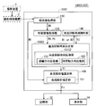
- FIG. 23 is a diagram illustrating a functional configuration of a control unit 31C used in the image processing apparatus 3C configured as the fourth embodiment of the present invention.
- the control unit 31C is used as an alternative to the control unit 31 (see FIG. 3) in the image processing apparatus 3 of the first embodiment.
- the difference from the first embodiment is that a blood flow suppression time restriction unit 140 is added.
- the blood flow suppression time determination unit 130C has the same function as the blood flow suppression time determination unit 130 of the first embodiment, but differs in that signals are exchanged with the blood flow suppression time restriction unit 140.
- the remaining configuration is the same as that of the image processing apparatus 3.
- FIG. 24 is a diagram showing a functional configuration of the control unit 31C2 used in the image processing device 3C2 as a modification of the image processing device 3C. That is, the difference from the image processing device 3C is that, as shown in FIG. 24, in the image processing device 3C2, the blood flow suppression time determination unit 130C2 includes a blood flow suppression time expansion unit 131C2, and the blood flow suppression time expansion unit 131C2 Is provided with an amplitude direction expansion unit 132 and a time axis direction expansion unit 133. That is, the image processing apparatus 3C2 adopts a configuration in which the blood flow suppression time restriction unit 140 is further added by combining the second and third embodiments.
- FIG. 24 shows an example of a modification of the image processing device 3C.
- the blood flow suppression time expansion unit 131C2 may include only the amplitude direction expansion unit 132 or only the time axis direction expansion unit 133. is there.
- Blood flow suppression time restriction unit 140 The blood flow suppression time constraint unit 140 (e1) satisfies the condition that the total time of analysis time required for blood flow analysis other than the blood flow suppression time TC in the entire time satisfies the first reference time or more, and ( e2) The blood flow so as to satisfy any one of the conditions in which the analysis time required for the blood flow analysis other than the blood flow suppression time TC for each respiratory cycle PC satisfies the second reference time or more. Restriction is imposed on the suppression time determination unit 130C or 130C2 (blood flow suppression time determination processing) (see FIGS. 23 and 24).
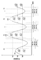
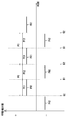
- FIG. 25 is a diagram for explaining a process for imposing a restriction on the blood flow suppression time determination process.
- the reference value SV in the third blood flow suppression time determination process is the threshold value THA.
- THB, THC corresponds to TCA, TCB, TCC (see FIG. 25).
- the blood flow suppression time constraint unit 140 shown in FIG. 24 imposes a constraint on the blood flow suppression time determination unit 130C2, the amplitude direction expansion unit 132 is limited and / or the time axis direction expansion unit 133 is limited. There is a case.
- the first threshold value TH1 (see FIGS. 14 and 16) in the first amplitude direction extension process corresponds to THA, THB, and THC (see FIG. 25), and the time width ⁇ T21. , ⁇ T23 (see FIGS. 14 and 16) correspond to ⁇ TA, ⁇ TB, and ⁇ TC (see FIG. 25), and blood flow suppression times TC21 and TC23 (see FIGS. 14 and 16) correspond to TCA, TCB, and TCC (see FIG. 25). ).
- the second threshold value TH2 (see FIGS. 15 and 17) in the second amplitude direction expansion process corresponds to the threshold values THA, THB, and THC (see FIG.
- Reference corresponds to ⁇ TA, ⁇ TB, ⁇ TC (see FIG. 25), and blood flow suppression times TC22, TC24 (see FIGS. 15, 17) correspond to TCA, TCB, TCC (see FIG. 25).
- the time width ⁇ T (see FIGS. 20 and 21) of any of the first to third time axis direction extension processes is set to ⁇ TA, ⁇ TB, and ⁇ TC (see FIG. 25).
- the blood flow suppression times TC31 and TC32 correspond to TCA, TCB, and TCC (see FIG. 25).
- the blood flow suppression time is changed in the order of TCA, TCB, and TCC (time widths are ⁇ TA, ⁇ TB, and ⁇ TC)
- the analysis time required changes in the order of TDA, TDB, and TDC.
- the blood flow suppression time restriction unit 140 e1 blood flow other than the blood flow suppression time TCA in the entire time.
- the condition that the total time (the total number of frame images) of the analysis-required analysis time TDA used for the analysis satisfies the first reference time (the first frame image number) N1 or more, and (e2) blood in each respiratory cycle PC
- the first reference time (first frame image number) N1 is preferably a time (number of frame images) corresponding to three cycles of blood flow
- Number) N2 is preferably a time (number of frame images) corresponding to one period of blood flow.
- the 1st ratio with respect to the total time of the analysis required time TDA used for blood flow analysis other than blood flow suppression time TCA is set to R1, and the analysis required for blood flow analysis other than blood flow suppression time TCA for every respiratory cycle PC. If the second ratio of the time TDA to the respiratory cycle PC is R2, it is preferable that the first ratio R1 and the second ratio R2 are at least 30% or more in terms of percentage.
- the blood flow suppression time restriction unit 140 does not satisfy the condition (e1) or (e2), and “the total time of the analysis time TDA required for the entire time is shorter than the first reference time N1” or “ If it is determined that the required analysis time TDA of the respiratory cycle PC is shorter than the second reference time N2 (that is, the required analysis time TDA is short), the blood flow suppression time determination unit 130C or 130C2 receives the blood flow suppression time. Is set to TCB having a shorter time width than TCA. If the blood flow suppression time is set to TCB, the time required for analysis increases from TDA to TDB, and the blood flow suppression time restriction unit 140 again satisfies the condition (e1) or (e2). Determine whether. When satisfied, the blood flow suppression time restriction unit 140 gives a command to the blood flow suppression time determination unit 130C or 130C2 so as to set the blood flow suppression time to TCB.
- the blood flow suppression time restriction unit 140 gives a command to the blood flow suppression time determination unit 130C or 130C2 so as to determine the blood flow suppression time as a TCC having a shorter time width than the TCB. If the blood flow suppression time is determined to be TCC, the analysis time required increases from TDB to TDC, and again, does the blood flow suppression time restriction unit 140 satisfy the above condition (e1) or (e2)? Determine whether or not.
- this series of loops is repeatedly executed until the above condition (e1) or (e2) is finally satisfied, and the time of the determination stage This can be realized by determining the width as the blood flow suppression time TC.
- the blood flow suppression time TC is sequentially determined from the longest time to the shorter time in the order of TCA ( ⁇ TA), TCB ( ⁇ TB), and TCC ( ⁇ TC).
- the present invention is not limited to this, and the blood flow suppression time TC may be sequentially determined in the order of TCC ( ⁇ TC), TCB ( ⁇ TB), and TCA ( ⁇ TA) from a shorter time width to a longer one.
- the series of loops are repeatedly executed until it is finally determined that the condition (e1) or (e2) is not satisfied, and the time width before the determination is set as the blood flow suppression time TC. It can be realized by setting.
- the blood flow suppression time TC can be determined while ensuring the blood flow analysis time required by the user.
- the blood flow suppression time constraint unit 140 illustrated in FIGS. 23 and 24 has been described. However, in the blood flow suppression time constraint unit 140 illustrated in FIG. Only the blood flow suppression time determination process has been described. In the blood flow suppression time restriction unit 140 shown in FIG. 23, the third blood flow suppression time determination process in which the blood flow suppression time is set with a time width is the mainstream, but in the following example, This is also effective in the case of the second blood flow suppression time determination process.
- FIG. 34 is a diagram for explaining processing that imposes restrictions on the first blood flow suppression time determination processing in the configuration of FIG. 23, where the vertical axis indicates the respiratory vibration value, and the horizontal axis indicates the time when the moving image was taken.
- the vertical axis indicates the respiratory vibration value
- the horizontal axis indicates the time when the moving image was taken.
- the blood flow suppression time TC11 is determined with a time width, and the time excluding the blood flow suppression time TC11 becomes the required analysis time TDE.
- the blood flow suppression time restriction unit 140 satisfies the condition (e1) “the total time of the required analysis time TDE in the entire time satisfies the first reference time N1 or more”, or the condition (e2)
- the blood flow suppression time determination unit 130C (the first blood flow is determined so as to satisfy any one of the conditions “required analysis time TDE for each respiratory cycle PC satisfies the second reference time N2 or more”. Restriction is imposed on the suppression time determination process (see FIG. 23).
- the blood flow suppression time TC11 When moving images are taken without holding the breath shown in FIG. 9, since the maximum value MX of the respiratory vibration value is determined as a single point, the blood flow suppression time TC11 has no time width. When the video is taken while holding the breath indicated by, since the maximum value MX of the respiratory vibration value is continuously present, the blood flow suppression time TC11 has a time width.
- the function is enabled. In particular, the condition (e2) is determined for each respiratory cycle PC, and thus is effective when analyzing for each respiratory cycle PC.
- FIG. 34 specialized and demonstrated to the 1st blood flow suppression time determination process
- the blood flow suppression time restrictions part 140 has the same effect also about a 2nd blood flow suppression time determination process.
- FIG. 26 is a diagram illustrating an operation flow of the image processing apparatus 3C according to the fourth embodiment.
- FIG. 26 representatively shows the case where the blood flow analysis content correction processing is the preprocessing of (a1) or (a2).
- steps SC1, SC2, SC4 to SC6 are the same as steps S1, S2, S4 to S6 in FIG.
- the blood flow suppression time restriction unit 140 satisfies the conditions (e1) and (e2).
- the blood flow suppression time determination unit 130C or 130C2 blood flow suppression time determination processing
- the suppression time TC is determined (see FIG. 25).
- the image processing apparatus 3C according to the fourth embodiment further includes the blood flow suppression time restriction unit 140 that imposes restrictions on the blood flow suppression time determination process.
- the blood flow suppression time restriction unit 140 that imposes restrictions on the blood flow suppression time determination process.
- FIG. 27 is a diagram illustrating a functional configuration of a control unit 31D used in the image processing device 3D configured as the fifth embodiment of the present invention.
- the control unit 31D is used as an alternative to the control unit 31 (see FIG. 3) in the image processing apparatus 3 of the first embodiment.
- a difference from the first embodiment is that a blood flow period detection unit 125 is added and a blood flow analysis value calculation unit having the same functions as the blood flow analysis value calculation unit 150 and the blood flow analysis correction unit 151 of the first embodiment.
- 150D and the blood flow analysis correction unit 151D include a blood flow cycle unitization unit 152.
- the remaining configuration is the same as that of the image processing apparatus 3.
- FIG. 28 is a diagram showing a functional configuration of the control unit 31D2 used in the image processing apparatus 3D2 as a modification of the image processing apparatus 3D. That is, the difference from the image processing device 3D is that, as shown in FIG. 28, in the image processing device 3D2, the blood flow suppression time determination unit 130D2 includes a blood flow suppression time expansion unit 131D2, and the blood flow suppression time expansion unit 131D2 Is provided with an amplitude direction expansion unit 132 and a time axis direction expansion unit 133. That is, the image processing device 3D2 adopts a configuration in which the blood flow cycle detection unit 125 and the blood flow cycle unitization unit 152 are further added by combining the second and third embodiments.
- FIG. 28 shows an example of a modification of the image processing device 3D.
- the blood flow suppression time expansion unit 131D2 may have a configuration including only the amplitude direction expansion unit 132 or a configuration including only the time axis direction expansion unit 133. is there.
- the blood flow cycle detection unit 125 detects the blood flow cycle of the target pixel in the target region using the plurality of frame images MI acquired by the moving image acquisition unit 110.
- a method for detecting a blood flow cycle for example, by taking a difference between frame images MI, a change in concentration of a clear pixel (target pixel) of a signal in a target region (that is, a change in blood flow) is set as a blood flow phase.
- the blood flow cycle can be detected based on the blood flow phase.
- FIG. 29 is a diagram illustrating a blood flow phase and a blood flow cycle detected by the blood flow cycle detection unit 125 from a plurality of frame images MI.
- FIG. 29A shows the positions of the target regions (target pixels) ROI1 and ROI2 on the frame image MI
- FIG. 29B shows the blood flow phase and blood flow cycle in the target pixels ROI1 and ROI2.
- the vertical axis in FIG. 29B represents the pixel values (blood flow) of the target pixels ROI1 and ROI2 obtained by taking the difference between the frame images MI
- the horizontal axis represents the time when the moving image was taken.
- FIG. 29B shows an example in which the blood flow periods BC1 to BC3 are detected based on the blood flow phase BH1 of the target region ROI1 detected by the blood flow period detection unit 125.
- a method for determining the blood flow periods BC1 to BC3 for example, a method of searching for a rise on the basis of the maximum value HP of the blood flow phase BH1 and determining it based on it can be adopted.
- the blood flow phase BH2 having a phase shift ⁇ d from the blood flow phase BH1.
- FIG. 29B shows the blood flow phase of the target region from pixels with clear signals.
- the blood flow phase BH1 of the target region ROI1 It is also possible to estimate the blood flow phase BH2 of the target region ROI2 after obtaining.
- Blood flow cycle unitization unit 152 In the blood flow cycle unit 152, the blood flow analysis is performed with the blood flow cycle unit BC detected by the blood flow cycle detector 125 with respect to the blood flow suppression time TC set in the blood flow suppression time determination process. Thus, the blood flow suppression time TC is adjusted.
- FIG. 30 is a diagram for explaining the process of adjusting the blood flow suppression time TC so that the blood flow analysis is performed in the blood flow cycle unit BC detected by the blood flow cycle detection unit 125.
- FIG. A part of the PH waveform is shown, and FIG. 30B displays the respiratory phase PH and the blood flow phase BH corresponding thereto in the region AR (one cycle) in FIG. 30A in a superimposed manner.
- the vertical axis in FIG. 30B represents the respiratory vibration value for the respiratory phase PH
- the horizontal axis represents the time when the moving image was taken in common. Indicates.
- the blood flow phase BH actually has a time interval from the highest value HP to the next highest value HP as shown in FIG. 29, but in FIG. 30B, this time interval is omitted and schematically shown. Yes.
- the blood flow suppression time TC13 (see FIG. 10) set in the third blood flow suppression time determination process of the blood flow suppression time determination unit 130 is This corresponds to the blood flow suppression time TC shown in FIG.
- the blood flow suppression times TC21 to TC24 (see FIGS. 14 to 17) determined by the amplitude direction expansion unit 132 of the blood flow suppression time determination unit 130D2 or
- the blood flow suppression times TC31 and TC32 (see FIGS. 20 and 21) determined by the time axis direction expansion unit 133 correspond to the blood flow suppression time TC shown in FIG.
- the blood flow suppression time TC shown in FIG. 30 may be a blood flow suppression time TC determined by causing the amplitude direction expansion unit 132 and the time axis direction expansion unit 133 to function with each other.
- the blood flow phase BH corresponding to the set blood flow suppression time TC is not normally set in the blood flow cycle unit BC, but in the blood flow cycle unit BC.
- the blood flow analysis value is lost in the blood flow cycle BC (that is, the regions AR2 and AR3) at the time that is the boundary of the blood flow suppression time TC, and the blood flow in the entire blood flow cycle BC There is a problem that the state cannot be grasped.
- the blood flow cycle unitization unit 152 performs blood flow analysis on the blood flow cycle unit BC (see FIG. 29) detected by the blood flow cycle detection unit 125 with respect to the blood flow suppression time TC.
- the blood flow suppression time TCR is determined again by adjusting and changing the flow suppression time TC. That is, the blood flow period BC in the areas AR2 and AR3 (in other words, the inspiratory phase EPHa and the expiratory phase EPHb in the areas AR2 and AR3) are also included in the blood flow suppression time TCR.
- Data for analysis exists in the blood flow cycle unit BC, and blood flow analysis can be performed for each blood flow cycle unit BC.
- the blood flow cycle unit 152 adjusts the blood flow suppression time TC to expand from the blood flow suppression time TC to the blood flow suppression time TCR. That is, in the case of reducing, as in the case of expanding, the blood flow analysis can be performed for each blood flow cycle unit BC at a time other than the blood flow suppression time TCR, while the blood flow cycle BC is more than in the case of expanding.
- the data amount for two cycles can be used for blood flow analysis.
- FIG. 31 is a diagram illustrating an operation flow of the image processing device 3D according to the fifth embodiment.
- FIG. 31 representatively shows the case where the blood flow analysis content correction processing is the preprocessing (a1) or (a2).
- steps SD1, SD3, SD6, and SD7 are the same as steps S1, S3, S5, and S6 of FIG.
- the following steps are added or changed by adding the blood flow cycle detection unit 125 and the blood flow cycle unitization unit 152 that did not exist in the first embodiment.
- step SD2 the respiratory information acquisition unit 120 performs the first or second respiratory information acquisition process.
- the blood flow cycle detection unit 125 uses the plurality of frame images MI acquired in step SD1 to perform the blood flow cycle of the target region. BC is detected (see FIG. 29).
- step SD4 the blood flow cycle unitization unit 152 performs blood flow analysis so that blood flow analysis is performed in the blood flow cycle unit BC with respect to the blood flow suppression time TC determined in the blood flow suppression time determination processing in step SD3.
- the flow suppression time TC is adjusted and determined again as the blood flow suppression time TCR (see FIG. 30).
- the blood flow analysis correction unit 151D excludes the blood flow analysis at the blood flow suppression time TCR determined in step SD4 or lowers the importance of blood flow analysis compared to other time zones. Perform correction processing. That is, the blood flow analysis content correction process here is a pre-process performed before the blood flow analysis process is performed, and the blood flow analysis correction unit 151D performs either of the processes (a1) or (a2). Do.
- the blood flow analysis correction unit 151D performs the blood flow cycle unit BC with respect to the blood flow suppression time TC determined in the blood flow suppression time determination process.
- a blood flow cycle unitization unit 152 is provided that adjusts the blood flow suppression time TC so that blood flow analysis is performed. Thereby, it is possible to prevent the blood flow analysis value from being lost for each blood flow cycle BC, and it is possible to grasp the blood flow state in the entire blood flow cycle BC.
- the image processing devices 3, 3A, 3B, 3C, 3C2, and 3D have been described separately for each embodiment, but these individual functions are consistent with each other. As long as they may be combined with each other.
- the blood flow suppression time restriction unit 140 when the blood flow suppression time restriction unit 140 imposes a restriction on the blood flow inhibition time determination unit 130C, a restriction is imposed on the third blood flow suppression time determination process (see FIG. 10). However, a configuration may be adopted in which restrictions are imposed on the second blood flow suppression time determination process (see FIG. 9). However, when adopting a configuration in which the blood flow suppression time restriction unit 140 imposes a restriction on the second blood flow suppression time determination process of the blood flow suppression time determination unit 130C, the blood flow is satisfied so as to satisfy the condition (e1). The suppression time restriction unit 140 imposes restrictions on the blood flow suppression time determination unit 130C.
- the blood flow period unitization unit 152 (see FIGS. 27 and 28) in the fifth embodiment is provided in the blood flow analysis correction unit 151D, it is not limited thereto.
- the blood flow cycle unitization unit 152 It is also possible to provide the flow suppression time determination unit 130.
- step SD1 in the fifth embodiment, the respiratory information and the blood flow period BC are acquired simultaneously, but the present invention is not limited to this. That is, if the blood flow cycle BC has been acquired by the stage before step SD4 in which the blood flow cycle unit 152 adjusts the blood flow suppression time TC so that the blood flow analysis is performed in the blood flow cycle unit BC. Good. Therefore, the structure which acquires blood flow period BC after acquiring respiration information may be sufficient, and the structure which acquires respiration information after acquiring blood flow period BC may be sufficient.
- FIG. 32 is a diagram for explaining the breathing phase PH when taking a moving picture while holding the breath during breathing.
- the respiratory phase PH in the case of taking a video while holding the breath is acquired as a constant respiratory vibration value during the time interval NB. Further, if the time interval NB while holding the breath does not belong to the maximum inspiration phase B1 or the vicinity thereof, it can be handled as analysis data. However, as described above, the respiratory vibration value is constant during the time interval NB, and the inclination of the respiratory phase PH is always zero in that interval, so the second blood flow suppression time determination process (see FIG. 9). ) May be erroneously detected as a maximum value (maximum inspiration phase B1) or a minimum value (maximum expiration phase B2). Therefore, by the third blood flow suppression time determination process (see FIG. 10), the blood flow suppression time TC is determined using the statistically determined respiratory vibration value or the like as the threshold XL (corresponding to the reference value SV in FIG. 10). (See FIG. 32).
- the respiratory phase PH is detected for each left and right lung field, and the blood flow suppression time TC is determined for each. It is desirable to do.
- blood flow can be measured more accurately when the change in respiratory vibration value is smaller (the slope of the respiratory phase PH is close to zero), so blood flow analysis is performed near the maximum expiratory phase B2. It is desirable to do.
- the subject may be an animal body as well as a human body.
- the first aspect is an image processing apparatus that performs blood flow analysis, and is composed of a plurality of frame images in which a state in which blood flow in a target region in a human or animal body changes is sequentially captured in a time direction.
- Blood flow analysis correction means for performing a blood flow analysis content correction process that excludes the frame image from the blood flow analysis target or lowers the importance of blood flow analysis compared to other time zones.
- a 2nd aspect is an image processing apparatus of a 1st aspect, Comprising:
- the said respiratory information acquisition process acquires the respiratory vibration value shown as a physical change value of the said lung field area
- the blood flow suppression time determination process includes a process of determining a time at which the respiratory vibration value becomes a maximum value as the blood flow suppression time.
- a 3rd aspect is an image processing apparatus of a 1st aspect, Comprising:
- the said respiratory information acquisition process acquires the respiratory vibration value shown as a physical change value of the said lung field area
- a respiratory cycle is recognizable from the respiratory vibration value, and the blood flow suppression time determination process uses, as the blood flow suppression time, a time at which the respiratory vibration value is maximum for each respiratory cycle. Processing to determine.
- a fourth aspect is the image processing apparatus according to the first aspect, wherein the respiratory information acquisition process uses a relative value that can be determined as to which of the inspiratory phase or the expiratory phase of the body.
- a process of acquiring a respiratory relative value indicating as the respiratory information, wherein a respiratory cycle is recognizable from the respiratory relative value, and the blood flow suppression time determination process includes: And a process of determining a time when the inhalation phase changes to the expiration phase as the blood flow suppression time.
- a fifth aspect is the image processing device according to the second to fourth aspects, wherein the blood flow suppression time determination means has the blood flow suppression so as to give a time width with reference to the blood flow suppression time.
- a 6th aspect is an image processing apparatus of a 2nd aspect, Comprising:
- the said blood flow suppression time determination means extends the said blood flow suppression time so that it may have a time width on the basis of the said blood flow suppression time.
- a blood flow suppression time expansion unit wherein the blood flow suppression time expansion unit uses a value that is smaller by a first value than a value at which the respiratory vibration value is maximized as a first threshold, and the respiratory vibration value
- An amplitude direction expansion unit that performs an amplitude direction expansion process for setting the time width according to a time when becomes equal to or greater than the first threshold.
- the seventh aspect is the image processing apparatus according to the sixth aspect, wherein the first value is (b1) based on a difference value between a value at which the respiratory vibration value is maximized and a value at which the respiratory vibration value is minimized. Any one of the calculated value and (b2) a predetermined constant value is included.
- an eighth aspect is the image processing device according to the third aspect, wherein the blood flow suppression time determination means extends the blood flow suppression time so as to have a time width based on the blood flow suppression time.
- a blood flow suppression time expansion unit that performs a second value that is less than a value at which the respiratory vibration value is maximized for each respiratory cycle.
- An amplitude direction expansion unit that performs an amplitude direction expansion process for setting the time width according to a time at which the respiratory vibration value is equal to or greater than the second threshold value.
- a ninth aspect is the image processing apparatus according to the eighth aspect, wherein the second value is set for each (c1) respiratory cycle, and the respiratory vibration value for each respiratory cycle is maximum. Any one of a value calculated based on a difference value between a value and a minimum value and (c2) a predetermined constant value is included.
- a tenth aspect is the image processing apparatus according to the first aspect, wherein the respiratory information acquisition process acquires a respiratory vibration value indicated as a physical change value of a lung field region of the body as the respiratory information.
- the blood flow suppression time determination processing includes processing for determining, as the blood flow suppression time, a time at which the respiratory vibration value is equal to or greater than a predetermined reference value.
- An eleventh aspect is the image processing device according to the third or fourth aspect, wherein the blood flow suppression time determination means is configured to give a time width based on the blood flow suppression time.
- a blood flow suppression time expansion unit that expands the time, and the time width is (d1) a first time width determined based on the time required for the inspiration phase and the expiration phase for each respiratory cycle A combined time width with a second time width determined based on time, (d2) a time width determined based on the time required for one cycle for each respiratory cycle, and (d3) predetermined Any one of the time widths is included.
- the twelfth aspect is the image processing apparatus according to any one of the second to eleventh aspects, and (e1) the blood flow analysis other than the blood flow suppression time in the entire time.
- a condition that the total analysis time to be used satisfies the first reference time or more, and (e2) the analysis time required for the blood flow analysis other than the blood flow suppression time in each respiratory cycle is the second time
- a thirteenth aspect is the image processing device according to any one of the first to twelfth aspects, further comprising a blood flow period detecting unit that detects a blood flow period of the target region.
- the blood flow analysis correction means adjusts the blood flow suppression time so that the blood flow analysis is performed in units of the blood flow period with respect to the blood flow suppression time determined in the blood flow suppression time determination process.
- a blood flow cycle unitizing unit is the image processing device according to any one of the first to twelfth aspects, further comprising a blood flow period detecting unit that detects a blood flow period of the target region.
- the blood flow analysis correction means adjusts the blood flow suppression time so that the blood flow analysis is performed in units of the blood flow period with respect to the blood flow suppression time determined in the blood flow suppression time determination process.
- a fourteenth aspect is the image processing device according to any one of the first to thirteenth aspects, wherein the blood flow analysis content correction processing is performed by the blood flow analysis in the moving image.
- the preprocessing includes (a1) a process for prohibiting the blood flow analysis process, and (a2) the blood flow with a lower degree of importance for the data at the blood flow suppression time among the analysis data.
- the post-processing includes (a3) the blood flow analysis value for the data at the blood flow suppression time among the blood flow analysis values as the blood flow analysis value. Processing not handled, and (a4) Treatment for reducing the severity of flow analysis values, including any of processing.
- the fifteenth aspect is the image processing device according to any one of the first to fourteenth aspects, wherein the target region includes a blood vessel region in a lung field region.
- a sixteenth aspect is a program that, when executed by a computer included in the image processing apparatus, causes the computer to function as the image processing apparatus according to any one of the first to fourteenth aspects. is there.
- the blood flow suppression time determination unit determines the blood flow suppression time based on the respiratory information
- the blood flow analysis correction unit captures the frame imaged at the blood flow suppression time.
- the blood flow analysis content correction processing is performed in which the image is excluded from the blood flow analysis target or the blood flow analysis importance is lowered as compared with other time zones. Therefore, blood flow analysis with blood flow analysis content correction processing becomes possible, and it is possible to avoid abnormal blood flow analysis values due to respiration. A value can be obtained. For this reason, it is possible to prevent the thrombus discrimination performance from being lowered, and to perform the blood flow dynamic diagnosis appropriately and efficiently.
- the blood flow suppression time determination process includes a process of determining the time at which the respiratory vibration value becomes the maximum value as the blood flow suppression time.
- the time at which the respiratory vibration value becomes the maximum value is determined as the blood flow suppression time for each respiratory cycle. Since the maximum value is obtained for each respiratory cycle, it is possible to determine, as the blood flow suppression time, the time that is assumed to have an adverse effect on the blood flow analysis value based on the physical change value of the lung field region. .
- the blood flow suppression time determination processing includes processing for determining, as the blood flow suppression time, the time at which the respiratory relative value changes from the inspiration phase to the expiration phase for each respiratory cycle. This makes it possible to determine, as the blood flow suppression time, the time at which blood flow is most suppressed and the blood flow analysis value is most adversely affected within each respiratory cycle. Robust effect that is not received. Further, by recognizing the respiratory cycle from the respiratory relative value, the respiratory information acquisition process can be simplified because it is not necessary to acquire the respiratory cycle based on the moving image.
- the blood flow suppression time determination means includes the blood flow suppression time expansion unit that extends the blood flow suppression time so as to have a time width with reference to the blood flow suppression time.
- the time width is generated according to the time when the respiratory vibration value is equal to or greater than the first threshold value, so that the time zone in which there is a high suspicion of blood flow is expanded and extracted more reliably. It becomes possible to determine the blood flow suppression time.
- the first respiratory amplitude value in the respiratory phase is the first value. Therefore, the first threshold value can be set appropriately without being too low.
- a predetermined constant value is used as the first value, it is possible to easily set the first threshold without specifically calculating the maximum respiration amplitude value within the respiration phase.
- the image processing device of the eighth aspect by setting a time width using a value that maximizes the respiratory vibration value for each respiratory cycle, it is possible to appropriately set a time when there is a high suspicion of blood flow suppression within the respiratory cycle. It is possible to extract and determine the blood flow suppression time. In addition, since the amplitude direction expansion processing is performed for each respiratory cycle, there is a robust effect that is not affected by other cycles.
- the second threshold when using a value calculated based on a difference value between a value at which the respiratory vibration value for each respiratory cycle is maximized and a value at which it is minimized as the second value, Since the second value can be determined based on the respiratory amplitude value, the second threshold can be appropriately set without becoming too low. In addition, when a predetermined constant value is used as the second value, it is possible to easily set the second threshold without specifically calculating the respiratory amplitude value.
- the blood flow suppression time determination process includes a process of determining a time when the respiratory vibration value is equal to or greater than a predetermined reference value as the blood flow suppression time. This makes it possible to easily extend and determine the blood flow suppression time without obtaining the maximum value for each respiratory cycle.
- the time width includes any one time width from (d1) to (d3).
- the blood flow suppression time can be easily extended and determined without depending on the respiratory vibration value at each time (that is, without calculating the time of the respiratory phase). Is possible.
- the image processing apparatus further includes blood flow suppression time restriction means for imposing restrictions on the blood flow suppression time determination process.
- the blood flow analysis value control means performs blood flow analysis in units of blood flow cycles with respect to the blood flow suppression time determined in the blood flow suppression time determination processing.
- a blood flow period unitizing unit for adjusting the blood flow suppression time is provided. Thereby, it is possible to prevent the blood flow analysis value from being lost for each blood flow cycle, and it is possible to grasp the blood flow state in the entire blood flow cycle.
- the blood flow analysis content correction processing includes any one of (a1) to (a4). That is, in the process of (a1) or (a2), the process is prohibited before the blood flow analysis process or the process of reducing the influence of the process is performed. Blood flow analysis can be performed. In particular, in the process (a1), since it is not necessary to perform the blood flow analysis process at the blood flow suppression time, the calculation time can be shortened without performing unnecessary calculations.
- the target region is a blood vessel region in the lung field region
- the radiation dynamic image capturing system captures a radiographic image in a situation in which the physical state of the target region of the subject periodically changes over time using a human or animal body as the subject.
- FIG. 35 is a diagram illustrating an overall configuration of a radiation dynamic image capturing system according to the sixth embodiment.
- the dynamic radiographic imaging system 200 includes an imaging apparatus 1, an imaging control apparatus 2 (imaging console), an image processing apparatus 3 (diagnosis console), and an electrocardiograph 4.
- the imaging device 1 and the electrocardiograph 4 are connected to the imaging control device 2 via a communication cable or the like, and the imaging control device 2 and the image processing device 3 are connected via a communication network NT such as a LAN.
- a communication network NT such as a LAN.
- the imaging device 1, the imaging control device 2, and the image processing device 3 have the same configuration as the imaging device 1, the imaging control device 2, and the image processing device 3 of the first embodiment shown in FIG. The description will be omitted as appropriate.
- the electrocardiograph 4 includes a phase detection unit 41, and the phase detection unit 41 performs an imaging operation by the imaging device 1 in response to a control signal from the CPU of the control unit 21. As basic information for synchronization, the phase of the heartbeat of the subject M is detected.
- the configuration of the electrocardiograph 4 is not an essential component in the present embodiment, and is not necessary when the first heartbeat period acquisition process of FIG. 38 described later is adopted.
- FIG. 36 is a diagram illustrating a general characteristic of the respiratory phase, in which FIG. 36 (a) shows a part of the waveform of the respiratory phase PH, and FIG. 36 (b) shows an area AR (1) in FIG. 36 (a). Respiratory phase PH in period) is shown.
- FIG. 37 is a diagram illustrating the relationship between the respiratory phase PH and the heartbeat phase BH. 36 and FIG. 37, the horizontal axis indicates the time (time direction) when the moving image is taken, and the vertical axis indicates a respiratory vibration value (details will be described later).
- the respiratory phase PH for one cycle PC is a maximum inspiratory phase IM corresponding to the maximum value B1 and a maximum expiratory phase EM corresponding to the minimum value B2 in the respiratory cycle PC (details).
- the interval of the respiratory phase PH from the maximum expiration phase EM to the maximum inspiration phase IM is called the inspiration phase PH1
- the interval of the respiratory phase PH from the maximum inspiration phase IM to the maximum expiration phase RM is Called PH2.
- the first half cycle PC1 of one cycle PC starting from the maximum expiration phase EM is referred to as an inspiration phase PH1
- the second half cycle PC2 is referred to as an expiration phase PH2.
- the heartbeat phase BH1 of the region AR1 corresponding to the maximum inspiration phase IM and the heartbeat phase BH2 of the region AR2 corresponding to the maximum expiration phase EM are the heartbeats of regions other than the regions AR1 and AR2. It can be seen that the pulsation is smaller compared to the phase BH.
- the blood pressure analysis is different because the pressure on the blood vessels is different in each phase state of the inspiration phase PH1 state and the expiration phase PH2. The value is adversely affected.
- the inspiration phase PH1 state and the expiration phase PH2 state it is desired to obtain an appropriate blood flow analysis value corresponding to each phase state.
- the image processing device 3 of the dynamic radiographic imaging system 200 in the sixth embodiment of the present invention obtains a blood flow analysis value in consideration of each phase state of the inspiratory phase PH1 state and the expiratory phase PH2 state. Image diagnosis can be performed appropriately and efficiently.
- control units 31E and 31E ′ mainly, the moving image acquisition unit 410, the respiratory information acquisition units 420 and 420 ′, the heartbeat cycle acquisition units 425 and 425 ′, the phase state determination unit 430, and the analysis range setting unit 440 are mainly used. And a blood flow analysis value calculation unit 450.
- control units 31E and 31E ′ as shown in FIGS. 38 and 39 is realized by executing a preinstalled program. It may be realized with.
- Moving Image Acquisition Unit 410 a state in which the blood flow of the target region in the body of the subject M captured by the reading control device 14 of the imaging device 1 changes from a plurality of frame images sequentially captured in the time direction. Acquires the composed moving image.
- the target region in the present embodiment is a region to be subjected to blood flow analysis, and assumes a blood vessel region in the lung field region. That is, as shown in FIGS. 38 and 39, the imaging control device 2 is interposed between the imaging device 1 and the image processing device 3, and the detection data (plurality of data stored in the storage unit 22 of the imaging control device 2). Frame image) is output to the communication unit 35 of the image processing apparatus 3 via the communication unit 25.
- the frame images M1 to M10 (MI) acquired by the moving image acquisition unit 410 are similar to the moving image acquisition unit 110 of the first embodiment.
- One cycle is continuously shot at a fixed shooting timing.
- Respiratory information acquisition unit 420, 420 ′ perform a respiratory information acquisition process for acquiring respiratory information in the subject M synchronized with the time when the frame image MI was captured. Specifically, in the respiratory information acquisition process, a respiratory vibration value indicated as a physical change value of the lung field region is used as respiratory information, and a respiratory vibration value having a respiratory cycle PC of at least one cycle is acquired. In addition, the respiration information acquisition process performs a process of calculating the maximum value B1 and the minimum value B2 of the respiration vibration value within the respiration cycle PC (see FIGS. 36 and 37).
- the respiratory vibration value detection method (first step) of the respiratory information acquisition process is roughly divided into two processes. Thereafter, a method (second step) for calculating the respiratory cycle PC and the maximum value B1 and the minimum value B2 of the respiratory vibration value in the respiratory cycle PC will be described.
- the first step of the first respiratory information acquisition process is a process of calculating a respiratory vibration value based on a plurality of frame images MI constituting the moving image acquired by the moving image acquisition unit 410 (see FIG. 38). ).
- the respiration information acquisition unit 420 calculates a respiratory vibration value using the plurality of frame images MI acquired by the moving image acquisition unit 410.
- the respiratory vibration value is an index for measuring a change in the size of the lung field region due to respiration. For example, “a distance between feature points of the lung field region (a distance from the lung apex to the diaphragm, etc.)” “Lung field area value (lung field region size)” “absolute position of diaphragm”, “pixel density value of lung field”, and the like.
- the respiratory vibration value is “the area value of the lung field” and “the distance between the feature points of the lung field” will be described as an example.
- the respiratory vibration value is the “area value of the lung field”
- the lung field is extracted for each of the left and right sides (see FIG. 5A), but the contour including the heart and spine regions (FIG. 5 ( You may extract as b) reference).
- the respiratory information acquisition unit 420 extracts the lung field contour OL using the plurality of acquired frame images MI, and calculates the number of pixels in the extracted region as the lung field area value. Is detected to obtain a respiratory vibration value (see FIG. 38).
- the distance between feature points in the lung field is calculated using a plurality of frame images MI. That is, the lung field is extracted in the same manner as described above, and two feature points are obtained from the extracted region, and the distance between the two points is obtained as a respiratory vibration value.
- a change in the distance between the feature points (respiration vibration value) is defined as a respiration phase PH.
- the lung apex is the upper end LT of the lung region, In this example, the intersection of the straight line extending from the apex in the body axis direction and the diaphragm is extracted as the lower end LB of the lung region.
- the apex of the lung is the upper end LT of the lung region, and the lateral angle is It is an example extracted as the lower end LB of the lung region.
- the respiratory information acquisition unit 420 extracts the contour OL of the lung field region using the acquired plurality of frame images MI, and detects the distance between the feature points from the extracted region.
- the vibration value is acquired (see FIG. 38).
- FIG. 40 is a schematic diagram of the respiratory phase PH showing the waveform data of the respiratory vibration values detected by the respiratory information acquisition unit 420 in time series, and the respiratory vibration values such as the area value of the lung field region, the distance between feature points, and the like. Is calculated and monitored in the time direction for each photographing timing TM. 40 indicates the amplitude direction AP of the respiratory phase PH.
- the first step of the second respiration information acquisition process is a process of measuring a respiratory vibration value by another device (external device) (see FIG. 39).
- another device external device
- the cycle detection sensor 15 of the cycle detection device 16 can be used.
- another method for detecting the respiratory vibration value from an external device there is a method of detecting the movement of the subject's chest using a respiratory monitor belt, and a method of detecting a respiratory airflow using an anemometer, These methods can also be applied.
- the respiratory information acquisition unit 420 ′ acquires a plurality of frame images MI via the moving image acquisition unit 410, and acquires respiratory vibration values synchronized therewith from an external device (see FIG. 39). Then, the respiratory vibration value is obtained as time series data as in FIG.
- Detection method of respiratory cycle PC maximum value B1, minimum value B2>
- the change in the respiratory vibration value detected in the first step is defined as a respiratory phase PH, and the maximum respiratory vibration value within the respiratory cycle PC and the respiratory cycle PC is obtained.
- a process of calculating the value B1 and the minimum value B2 is performed (see FIG. 40).
- one cycle of the breathing cycle (breathing cycle) PC is composed of inspiration and expiration, and consists of one expiration and one inspiration.
- inspiration cycle the area of the lung field in the thorax increases as the diaphragm lowers and breathes in.
- the maximum inspiration phase IM is when the inspiration is taken in to the maximum (inspiration and expiration conversion point).
- exhalation the area of the lung field decreases as the diaphragm rises and exhales, but the maximum exhalation phase EM is when exhaled to the maximum (conversion point of exhalation and inspiration).
- the respiratory cycle PC is determined by sequentially calculating the time when the respiratory vibration value becomes the maximum value and the minimum value over the entire time, and the maximum value B1 of the respiratory vibration value within the respiratory cycle PC is determined.
- This is a method for determining the minimum value B2.
- the maximum value (maximum inspiration phase IM) and the minimum value (maximum expiration phase EM) of the respiratory vibration value are calculated in a state where the respiratory vibration value in the entire time is smoothed and the high frequency noise component is reduced. .
- the second method is a method of detecting the time when the respiratory cycle PC is detected first and the respiratory vibration value becomes the maximum value and the minimum value for each respiratory cycle PC.
- the difference from the first method is that the maximum value (that is, the maximum inspiration phase IM) and the minimum value (maximum expiration phase EM) of the respiratory vibration value are calculated not in the entire time but in the respiratory cycle PC.
- the maximum value and the minimum value may be extracted in a state where the respiratory vibration value is smoothed to reduce the high-frequency noise component.
- the respiratory information acquisition units 420 and 420 ′ use the change in the respiratory vibration value as the respiratory phase PH, and detect the respiratory cycle PC and the maximum value B1 and the minimum value B2 of the respiratory vibration value within the respiratory cycle PC ( (See FIG. 40).
- the heartbeat cycle acquisition process is roughly divided into two processes, and each is described below.
- the heartbeat period acquisition unit 425 uses the captured image acquired by the moving image acquisition unit 410 to calculate the amount of motion of the heart wall. This is a process for acquiring a cycle. Specifically, the phase of the pulsation of the heart at the timing when each frame image is captured is detected by detecting the fluctuation of the heart wall from the moving image. Then, the heartbeat cycle is determined based on the phase of the heartbeat.
- FIG. 41 is a schematic diagram illustrating the variation of the heart wall captured in the moving image. As shown in FIG. 41, the variation of the lateral width of the heart is adopted as an example of the variation of the heart wall HL. 41 (a) to 41 (c) illustrate a state in which the lateral width of the heart increases from w1 to w3 in the process of expanding the heart.
- the heartbeat cycle acquisition unit 430 detects the heartbeat cycle by detecting the width of the heart from each frame image.
- a method for detecting the lateral width of the heart for example, a method for detecting the outline of the heart can be cited.
- a method for detecting the outline of the heart various known methods can be employed.
- a model indicating the shape of the heart
- a feature point in the X-ray image Detecting the outline of the heart by matching with the feature points of the heart model (eg “Image feature analysis and computer-aided diagnosis in digital radiography: Automated analysis of sizes of heart and lung in chest images”, Nobuyuki Nakamori et al., Medical Physics, Volume 17, Issue 3, May, 1990, pp.342-350.
- FIG. 42 is a schematic view illustrating the relationship between the time when the image was taken and the lateral width of the heart for a plurality of frame images constituting the moving image.
- the horizontal axis indicates time
- the vertical axis indicates the width of the heart
- the value of the width of the heart from which a circle is detected is illustrated.
- the lateral width of the heart captured at time t is Hwt
- the lateral width of the heart captured at time t + 1 is Hwt + 1
- (Hwt + 1 ⁇ Hwt) ⁇ 0 holds, it is captured at time t.
- the obtained frame image is classified when the heart is expanded, and if (Hwt + 1 ⁇ Hwt) ⁇ 0 holds, the frame image captured at time t is classified when the heart contracts.
- the lateral width of the heart that is, the fluctuation of the heart wall HL
- the heartbeat period acquisition unit 425 can automatically acquire the heartbeat period by detecting the heartbeat period based on the motion of the heart wall captured in the moving image.
- FIG. 43 is a diagram illustrating one cycle HBC of the electrocardiogram waveform of the subject M.
- the horizontal axis indicates the time
- the vertical axis indicates the magnitude (voltage) of the electric signal
- P wave, Q wave, R wave, S wave, T wave, and U wave shapes are shown. Curves showing changes in electrical signals including curves Pp, Qp, Rp, Sp, Tp and Up are shown.
- the heart cycle acquisition unit 425 ′ detects the above points (Pp, Qp, Rp, Sp, Tp, and Up) based on the detection result of the heartbeat phase BH acquired from the phase detection unit 41, A heartbeat cycle HBC is acquired.
- the detection operation by the phase detection unit 41 is performed in synchronization with the imaging operation by the imaging device 1 (see FIG. 35).
- the heartbeat period acquisition unit 425 ′ can automatically acquire a periodic time change of the heart by acquiring the heartbeat period HBC from the outside.
- Phase State Determination Unit 430 determines whether the respiratory information acquired by the respiratory information acquisition unit 420 belongs to the inhalation phase PH1 state or the expiration phase PH2 state, and obtains a phase state determination result. I do.
- the “phase state determination result” refers to the result of either the inspiratory phase PH1 state or the expiratory phase PH2 state.
- the phase state determination process is based on the maximum value B1 and the minimum value B2 of the respiratory vibration values in the respiratory cycle PC calculated by the respiratory information acquisition unit 420, and the respiratory vibration value is in the inspiratory phase PH1 state or This is a process of determining which phase state of the expiratory phase PH2 belongs.
- the maximum value B1 of the respiratory vibration value within the respiratory cycle PC calculated by the respiratory information acquisition unit 420 is set as the maximum inspiration phase IM, and the minimum value B2 Is determined as the maximum expiration phase EM, the phase from the maximum expiration phase EM to the maximum inspiration phase IM is determined as the inspiration phase PH1, and the phase from the maximum inspiration phase IM to the maximum expiration phase EM is determined as the expiration phase PH2.
- a state determination result is obtained.
- the analysis range setting unit 440 performs an analysis range setting process for setting a blood flow analysis range in at least one of the inspiratory phase PH1 state and the expiratory phase PH2 state based on the respiration information and the phase state determination result.
- the “respiration information” here refers to the respiratory phase PH based on the respiratory vibration value, the respiratory cycle PC, and the maximum value B1 and the minimum value B2 of the respiratory vibration value within the respiratory cycle PC.
- the analysis range setting unit 440 acquires the respiration information from the phase state determination unit 430 (see FIGS. 38 and 39).
- the analysis range setting process sets the blood flow analysis range so that the respiratory cycle PC includes at least one cycle of the heart rate cycle HBC while setting the blood flow analysis range based on the respiratory vibration value of at least one cycle. Perform the process.
- the blood flow analysis range includes an inspiration phase analysis range RA1 and an expiration phase analysis range RA2 corresponding to the inspiration phase PH1 state and the expiration phase PH2.
- the respiratory cycle PC may be one cycle.
- both the inspiration phase analysis range RA1 and the expiration phase analysis range RA2 are set will be described, but only one of the ranges (either RA1 or RA2) is set. Also good.
- the blood flow analysis range is defined as (a) “amplitude value range RB1” (FIG. 44 described later) set based on the amplitude value of the respiratory vibration value with respect to the amplitude direction AP (see FIG. 40) in the respiratory vibration value. Etc.) and for the imaging time direction, (c) “analysis target period RT1” (FIG. 44 described later) to be analyzed among the respiratory periods PC of the respiratory vibration values acquired in the respiratory information acquisition process. (D) or (d) “analysis target period RT2 for each phase” (refer to FIG. 45 to be described later) corresponding to one of the inspiration phase PH1 and the expiration phase PH2 in the period set as the analysis target period. Any one range is adopted.
- the blood flow analysis range in the sixth embodiment is a range that satisfies the “amplitude value range RB1” and the “analysis target period RT1”, or the “amplitude value range RB1” and the “phase-specific analysis target”.
- the range is any of the ranges satisfying the cycle “RT2”.
- the “amplitude value range RB1” here is (a1) a range set based on a preset first range, or (a2) a maximum value of respiratory vibration values within the respiratory cycle PC.
- the setting of “first range”, “analysis target period RT1” and “phase-specific analysis target period RT2” is set by the user of the image processing apparatus 3 (3 ′) as shown in FIGS. This is performed by inputting via the operation unit 33.
- a plurality of blood flow analysis ranges RA have the same range of respiratory vibration values within the plurality of blood flow analysis ranges RA.
- the analysis range setting process causes the blood flow analysis value calculation unit 450 to perform any one of the processes (e1) to (e3) described later and the process (f).
- the processes (e1) to (e3) and the process (f) will be described in detail later.
- Example of analysis range setting process> 44 to 46 are diagrams for explaining the analysis range setting process, in which the horizontal axis indicates the time when the moving image is captured, and the vertical axis indicates the respiratory vibration value.
- the amplitude value range RB1 in FIGS. 44 to 46 will be described as a representative case where the amplitude range RB1 is set as the first range (a1).
- a method of automatically setting based on the maximum value B1 and the minimum value B2 may be used. Further, when the method (a2) is adopted, it is preferable that the value be set in the vicinity of the middle between the maximum value B1 and the minimum value B2.
- the blood flow analysis range RA shown in FIG. 44 satisfies the amplitude value range RB1 for the amplitude direction AP in the respiratory vibration value, and the respiratory vibration value acquired by the respiratory information acquisition process for the imaging time direction.
- the respiratory cycles PC three cycles are set to satisfy the analysis target cycle RT1.
- the blood flow analysis range RA is set as RA11, RA12, RA13 in the order of imaging time in the inhalation phase analysis range RA1 in the inspiration phase PH1, and the expiration phase analysis range RA2 in the expiration phase PH2 is in the order of imaging time RA21, RA22. , RA23.
- the blood flow analysis range RA shown in FIG. 45 is set as the amplitude value range RB1 in the same way as in FIG. 44 for the amplitude direction AP of the respiratory vibration value, but for the imaging time direction.
- the analysis target cycle RT1 similar to FIG. 44 only the half cycle PC1 (see FIG. 36) corresponding to the intake phase PH1 is set as the analysis target cycle RT2 for each phase.
- RA11, RA12, and RA13 are set in order of the photographing time as the inspiration phase analysis range RA1.
- the case of the inhalation phase PH1 is assumed as the phase-by-phase analysis target period RT2, but the same applies to the case of the expiration phase PH2. That is, in the case of the expiration phase PH2, the difference from the case of the inspiration phase PH1 (FIG. 45) is that only the half cycle PC2 (see FIG. 36) corresponding to the expiration phase PH2 is set as the analysis target cycle RT2 for each phase. In the blood flow analysis range RA, only the RA21, RA22, and RA23 are set in the order of imaging time as the expiration phase analysis range RA2.
- the entire range is once determined in the analysis target cycle RT1 set in units of cycles.
- the amplitude value range RB1 in the amplitude direction AP in the respiratory vibration value can be set separately as RB11, RB12, RB13 in order from the larger amplitude value of the respiratory vibration value. . Then, as in FIG. 46, as in FIG.
- the inspiration phase analysis range RA1 is RA113, RA112, RA111, RA123, RA122, RA121, RA133, RA132, RA131 are set, and the expiratory phase analysis range RA2 is set to a total of 18 ranges as RA211, RA212, RA213, RA221, RA222, RA223, RA231, RA232, RA233 in order of imaging time. It becomes possible to do.
- each of the blood flow analysis ranges RA (inspiration phase analysis range RA1 and / or expiration phase analysis range RA2) set by the analysis range setting process has at least one heartbeat cycle HBC. (See FIG. 47A described later) It is determined whether or not it is included (see FIGS. 38 and 39).
- the analysis range setting unit 440 formally determines the blood flow analysis range RA.
- the analysis range determination unit 445 determines that the heartbeat cycle HBC does not include at least one cycle, the analysis range setting process includes “imaging time direction” and / or “amplitude direction AP of respiratory vibration value” plus The blood flow analysis range RA is urged to be expanded again in the direction and / or minus direction.
- the analysis range determination unit 445 performs the same determination as above again on the reset blood flow analysis range RA.
- the analysis range determination unit 445 repeatedly executes this series of loops until it is finally determined that at least one heartbeat cycle HBC is included, and the analysis range setting unit 440 sets the final result as the blood flow analysis range RA. Determine formally.
- Blood flow analysis value calculation unit 450 performs a blood flow analysis on the frame image MI in the blood flow analysis range RA set by the analysis range setting unit 440, so that the inspiratory phase PH1 state and the expiratory phase PH2 state The blood flow analysis value calculation process for obtaining the blood flow analysis value in at least one state is performed.
- the blood flow analysis value calculation process refers to a process of obtaining blood flow analysis values individually by performing blood flow analysis independently of each other in the inspiration phase analysis range RA1 and the expiration phase analysis range RA2.
- the blood flow analysis here is basically processing obtained by taking a difference between a plurality of frame images MI included in a moving image, but processing such as noise removal is also performed as necessary.
- the blood flow analysis method described in JP 2012-110399 A can be employed.
- the blood flow analysis value calculation process calculates at least two cycle-unit blood flow analysis values SM in at least two respiratory cycles PC. And a process of finally obtaining a blood flow analysis value SMR using the at least two periodic unit blood flow analysis values SM (see FIGS. 48 and 49 described later in detail).
- the blood flow analysis value calculation unit 450 is instructed to perform the following processing from the analysis range setting process of the analysis range setting unit 440 when there are a plurality of the “same vibration range” described above. Implement according to the contents.
- the processing is (e1) calculating an average value within a range indicating an average value as a blood flow analysis value SMR for a plurality of periodic unit blood flow analysis values SM calculated within a plurality of the same vibration ranges.
- the blood flow analysis value calculation unit 450 outputs the blood flow analysis value SMR or the final image RG used for image diagnosis to the storage unit 32 and the display unit 34 (see FIGS. 38 and 39).
- Periodic blood flow analysis value SM> 47 to 49 are diagrams for explaining blood flow analysis value calculation processing.
- FIG. 47A is a diagram for schematically explaining the relationship between the frame image MI and the heartbeat cycle HBC in each blood flow analysis range RA, where the horizontal axis indicates the imaging time, and the vertical axis indicates the first heartbeat cycle. In the case of the acquisition process, the lateral width of the heart is shown, and in the case of the second cardiac cycle acquisition process, an electric signal detected from the electrocardiograph 4 is shown.
- FIG. 47B shows a difference image DG generated from the sum of the difference values between the frame images MI in each blood flow analysis range RA in FIG. 47A (that is, corresponding to the periodic unit blood flow analysis value SM). Show.
- Each blood flow analysis range RA here is representative of one of the inspiration phase analysis ranges RA11 to RA13 and the expiration phase analysis ranges RA21 to RA23 shown in FIG. Yes.
- FIG. 47 (a) seven frame images MI in the blood flow analysis range RA and six time differences ⁇ t1 to ⁇ t6 are assumed. Set according to the frame rate.
- each blood flow analysis range RA set by the analysis range setting unit 440 through the determination of the analysis range determination unit 445 is set to include at least one heartbeat cycle HBC. Yes.
- the difference between the frame images MI in each blood flow analysis range RA is taken in the order of the photographing time, and the difference values d1 to d6 corresponding to the time differences ⁇ t1 to ⁇ t6 are obtained, thereby obtaining one cycle HBC of the heartbeat.
- a difference value is obtained.
- the periodic unit blood flow analysis value SM as the sum of the difference values d1 to d6 one difference image DG is obtained as shown in FIG. 47 (b).
- each of the difference values d1 to d6 corresponds to the blood flow in the lung field.
- the blood flow is concentrated near the heart, so that there is a large concentration difference on the frame image near the heart (for example, see the region dr in FIG. 47B).
- the difference value becomes large.
- blood flow concentrates in a region far from the heart, so in a region far from the heart (for example, see region du in FIG. 47B). The density difference increases on the frame image, and the difference value increases.
- the difference value (density difference) having a large value moves on the frame image (spatially changes) depending on the shooting time (temporal change) between the frame images. Then, the difference between the frame images MI corresponding to one heartbeat cycle HBC is taken and the sum of each difference value is obtained to obtain the cycle unit blood flow analysis value SM, and one sheet based on the cycle unit blood flow analysis value SM.
- the difference image DG it is possible to examine the whole picture of blood flow around the entire lung field region. For this reason, when the subject M is not a healthy person, the movement of blood flow inside the lung field can be grasped, for example, a region where blood flow does not flow in the lung field region can be found.
- Blood flow analysis value SMR and final image RG> Subsequently, using FIG. 44, FIG. 48 and FIG. 49, blood flow analysis is performed independently in each of the inspiration phase analysis range RA1 and the expiration phase analysis range RA2, and a plurality of periodic unit blood flow analysis values SM are obtained. A process for finally obtaining the blood flow analysis value SMR will be described.
- the inspiratory phase analysis range RA1 (RA11 to RA13) and the expiratory phase analysis range RA2 (RA21 to RA23) shown in FIG. 44 are subjected to blood flow analysis value calculation processing independently of each other. That is, in the example of FIG. 44, three of the same vibration ranges exist in three inspiratory phases PH1 and three exhaled phases PH2.
- the blood flow analysis value calculation processing is performed in the inspiration phase analysis range RA11, RA12, and RA13 (see FIG. 44), respectively.
- Analysis values SM11, SM12, SM13 are calculated (see FIG. 48).
- periodic unit blood flow analysis values SM21, SM22, and SM23 are calculated (see FIG. 49).
- the difference images DG11 to DG13 and DG21 to DG23 shown in FIGS. 48 and 49 are generated based on the periodic unit blood flow analysis values SM11 to SM13 and SM21 to SM23, but are shown for convenience of explanation. Actually, it is not necessary to generate as an image, and it is important to obtain periodic unit blood flow analysis values SM11 to SM13 and SM21 to SM23.
- any one of the above (e1) to (e3) is performed on the periodic unit blood flow analysis values SM11 to SM13 within the inspiration phase analysis range RA1. That is, as shown in FIG. 48, when the process of (e1) is adopted, an in-range average value indicating an average value of the periodic unit blood flow analysis values SM11 to SM13 is calculated as the blood flow analysis value SMR1. Process. When the process (e2) is adopted, the process calculates the maximum value within the range indicating the maximum value among the periodic unit blood flow analysis values SM11 to SM13 as the blood flow analysis value SMR1. Further, when the process (e3) is employed, a process is performed for calculating the minimum value in the range indicating the minimum value among the periodic unit blood flow analysis values SM11 to SM13 as the blood flow analysis value SMR1.
- the blood flow analysis value calculation process performs any one of the processes (e1) to (e3). That is, as shown in FIG. 49, when the process of (e1) is adopted, an in-range average value indicating an average value of the periodic unit blood flow analysis values SM21 to SM23 is calculated as the blood flow analysis value SMR2. Process. When the process (e2) is employed, the process calculates the blood flow analysis value SMR2 as the blood flow analysis value SMR2 within the range indicating the maximum value among the periodic unit blood flow analysis values SM21 to SM23. Further, when the process (e3) is employed, a process is performed in which the minimum value within the range indicating the minimum value among the periodic unit blood flow analysis values SM21 to SM23 is calculated as the blood flow analysis value SMR2.
- the determination method of the in-range maximum value and the in-range minimum value of (e2) and (e3) for example, there is a method of determining on the basis of a pixel value (density) in a diagnosis region where the user wants to perform image diagnosis.
- the blood flow analysis values SMR1 and SMR2 are obtained individually by performing the blood flow analysis independently in the inspiration phase analysis range RA1 and the expiration phase analysis range RA2.
- the blood flow analysis value calculation process within the analysis range RA1 for the inspiratory phase includes (f) any one of the average value within the range, the maximum value within the range, and the minimum value within the range as the blood flow analysis value SMR1.
- the final image RG1 is finally generated using the blood flow analysis value SMR1.
- the blood flow analysis value calculation process is individually performed in the expiration phase analysis range RA2 in any one of (f) in-range average value, in-range maximum value, and in-range minimum value.
- One is used as the blood flow analysis value SMR2
- the final image RG2 is generated using the blood flow analysis value SMR2.
- the blood flow analysis value calculation unit 450 outputs the blood flow analysis values SMR1, SMR2 or the final images RG1, RG2 used for image diagnosis to the storage unit 32 and the display unit 34.
- Periodic blood flow analysis value SM a method for calculating the periodic unit blood flow analysis value SM will be described below.
- FIG. 46 there are three types of the same vibration range in the three inspiration phases PH1 and the three expiration phases PH2. Specifically, the intake phase analysis range RA1a (RA111 to RA131), the intake phase analysis range RA1b (RA112 to RA132), and the intake phase analysis are included in the three intake phases PH1 as three types of the same vibration range.
- a range RA1c (RA113 to RA133) exists.
- an expiration phase analysis range RA2a (RA211 to RA231)
- an inspiration phase analysis range RA2b (RA212 to RA232)
- an inspiration phase analysis range RA1c (RA213 to RA233) exist.
- the periodic unit blood flow analysis values SM111 to SM131 are calculated from the intake phase analysis range RA1a (RA111 to RA131), and the intake phase analysis range RA1b is calculated.
- Cycle unit blood flow analysis values SM112 to SM132 are calculated from (RA112 to RA132), and cycle unit blood flow analysis values SM113 to SM133 are calculated from the inspiration phase analysis range RA1c (RA113 to RA133).
- the blood flow analysis value calculation process calculates the cycle unit blood flow analysis values SM211 to SM231 from the expiratory phase analysis range RA2a (RA211 to RA231), and the expiratory phase analysis range RA2b (RA212 to RA2b).
- the periodic unit blood flow analysis values SM212 to SM232 are calculated from RA232), and the periodic unit blood flow analysis values SM213 to SM233 are calculated from the expiratory phase analysis range RA2c (RA213 to RA233).
- Blood flow analysis value SMR and final image RG a method for calculating the blood flow analysis value SMR and the final image RG will be described below.
- the blood flow analysis is performed by performing any one of the processes (e1) to (e3) on the periodic unit blood flow analysis values SM111 to SM131.
- the value SMR1a is calculated, and any one of the processes (e1) to (e3) is performed on the periodic unit blood flow analysis values SM112 to SM132 and also on the periodic unit blood flow analysis values SM113 to SM133.
- blood flow analysis values SMR1b and SMR1c are calculated.
- the blood flow analysis value calculation processing is performed by performing any one of the processes (e1) to (e3) on the periodic unit blood flow analysis values SM211 to SM231.
- each of the processes (e1) to (e3) described above is performed for the periodic unit blood flow analysis values SM212 to SM232 and also for the periodic unit blood flow analysis values SM213 to SM233.
- blood flow analysis values SMR2b and SMR2c are calculated.
- the blood flow analysis value calculation processing is any one of (f) in-range average value, in-range maximum value, and in-range minimum value in each of the inspiration phase analysis ranges RA1a, RA1b, and RA1c.
- the blood flow analysis value calculation processing is performed in each of the expiration phase analysis ranges RA2a, RA2b, and RA2c.
- blood flow analysis values SMR2a, SMR2b, SMR2c are used as one of the blood flow analysis values SMR2a, SMR2b, SMR2c, and final images RG2a, RG2b, RG2c are finally generated.
- the blood flow analysis value calculation unit 450 uses six blood flow analysis values SMR1a, SMR1b, SMR1c, SMR2a, SMR2b, SMR2c, or final images RG1a, RG1b, RG1c, RG2a, RG2b, and RG2c used for image diagnosis.
- the data is output to the storage unit 32 and the display unit 34.
- FIG. 50 is a flowchart for explaining a basic operation realized in the image processing apparatus 3 (3 ′) according to this embodiment, and FIG. 51 is a schematic diagram simply showing the flow of the basic operation. Since the individual functions of each unit have already been described (see FIGS. 38 and 39), only the overall flow will be described here.
- step S101 the moving image acquisition unit 410 of the control unit 31E (31E ′) captures a moving image (a plurality of frame images MI) photographed by the reading control device 14 of the photographing device 1. Obtained via the imaging control device 2.
- step S102 the respiratory information acquisition unit 420 or 420 ′ performs a first or second respiratory information acquisition process for acquiring respiratory information synchronized with the imaging time at which the frame image was captured, and the respiratory phase based on the respiratory vibration value.
- the PH, the respiratory cycle PC, and the maximum value B1 and the minimum value B2 of the respiratory vibration value within the respiratory cycle PC are detected (see FIGS. 5, 6, 40, 51 (a) and 51 (b)). .
- step S103 the phase state determination unit 430 determines whether the respiratory vibration value acquired in step S102 belongs to the inhalation phase PH1 state or the expiration phase PH2 state, and obtains the phase state determination result (FIG. 51 (c)).
- step S104 the heartbeat cycle acquisition unit 425 or 425 ′ performs the first or second heartbeat cycle acquisition process synchronized with the shooting time at which the frame image was shot to detect the heartbeat cycle HBC (FIGS. 41 to 43).
- step S104 may be processed before step S102 and step S103, or may be processed after step S102 and step S103, in addition to the configuration processed in parallel with step S102 and step S103. That is, step S104 only needs to be processed before step S105.
- step S105 the analysis range setting unit 440 sets the blood flow analysis range RA in at least one of the inspiration phase PH1 state and the expiration phase PH2 state based on the phase state determination result acquired in step S104.
- the blood flow analysis range RA is set based on the determination result performed by the analysis range determination unit 445 (see FIGS. 44 to 46 and FIG. 51 (d)).
- step S105 the analysis range setting unit 440 performs the blood flow analysis value calculation unit 450 (450) so as to perform any one of the processes (e1) to (e3) on the periodic unit blood flow analysis value SM. A command is given to blood flow analysis value calculation processing.
- the blood flow analysis value calculation unit 450 obtains blood flow analysis values SMR individually by performing blood flow analysis independently in the inspiration phase analysis range RA1 and the expiration phase analysis range RA2. Further, when there are a plurality of the same vibration ranges, the blood flow analysis value calculation processing calculates a periodic unit blood flow analysis value SM, and the above (e1) commanded in step S105 within the plurality of the same vibration ranges. ) To (e3) are performed to calculate the blood flow analysis value SMR. Then, any one of the average value within the range, the maximum value within the range, and the minimum value within the range in (f) is determined as the blood flow analysis value SMR, and the final image RG is determined using the blood flow analysis value SMR. Is finally generated (see FIGS. 47 to 49).
- step S107 the blood flow analysis value calculation unit 450 outputs the blood flow analysis value SMR or the final image RG in step S106 on the storage unit 32 or the display unit 34 (see FIGS. 38 and 39). This operation flow is terminated.
- RA is set, and blood flow analysis is performed on the frame image MI in the blood flow analysis range RA, thereby obtaining the blood flow analysis value SMR in the at least one state.
- the blood flow analysis range RA is set so as to include at least one heartbeat cycle HBC.
- the blood flow analysis value SMR is obtained in a state in which at least one heartbeat period HBC is included. For this reason, it becomes possible to grasp
- blood flow analysis values SMR (SMR1, SMR2) are individually obtained by performing blood flow analysis independently in the inspiration phase analysis range RA1 and the expiration phase analysis range RA2. Process.
- SMR1, SMR2 blood flow analysis values
- the blood flow analysis range RA includes an amplitude value range RB1 for the amplitude direction AP of a respiratory vibration value having a respiratory cycle PC of one cycle or more, and an analysis target cycle RT1 or a phase-specific analysis target cycle RT2 for the imaging time direction.
- an amplitude value range RB1 for the amplitude direction AP of a respiratory vibration value having a respiratory cycle PC of one cycle or more By setting any one of the ranges to satisfy the range, it is possible to set the blood flow analysis range RA according to the user's application.
- the blood flow analysis value calculation process is performed by setting the analysis target period RT2 for each phase. Since only one phase state needs to be calculated, the calculation time can be shortened as compared with the case where the calculation period is set (see FIGS. 44 and 45).
- the amplitude value range RB1 is set based on the above (a1) preset first range, the user can automatically determine without considering the respiratory vibration value.
- (a2) the respiratory vibration value within the respiratory cycle PC is set based on the maximum value B1 and the minimum value B2, an appropriate amplitude value range RB1 corresponding to the respiratory vibration value is automatically set. It becomes possible.
- the blood flow analysis value calculation process obtains at least two cycle-unit blood flow analysis values SM in at least two respiratory cycles PC, and uses the at least two cycle-unit blood flow analysis values SM to calculate the blood flow analysis value SMR. The process finally obtained is performed.
- the final blood flow analysis value SMR can be obtained by comprehensively considering a plurality of periodic unit blood flow analysis values SM, which cannot be realized when blood flow analysis is performed for one cycle of respiration, and the inspiratory phase PH1 state and The determination can be made in at least one of the expiration phase PH2. For this reason, blood flow image diagnosis can be performed more appropriately and efficiently.
- the respiratory cycle PC is calculated based on the respiratory vibration value, and the maximum value B1 and the minimum value B2 of the respiratory vibration value for each respiratory cycle PC are calculated.
- the amplitude value range is set to the maximum value B1 and the minimum value B2 for each respiratory cycle PC.
- an individual amplitude value range RB1 can be set for each respiratory cycle PC.
- phase state determination process based on the maximum value B1 and the minimum value B2 of the respiratory vibration value within the respiratory cycle PC, whether the respiratory vibration value belongs to the phase state of the inhalation phase PH1 or the expiration phase PH2 Determine. Accordingly, the phase state of the respiratory vibration value is appropriately and easily determined based on the maximum inspiration phase IM and the maximum expiration phase EM corresponding to the maximum value B1 and the minimum value B2 of the respiratory vibration value within the respiratory cycle PC. (See FIGS. 36 and 40).
- an in-range average value indicating an average value of a plurality of periodic unit blood flow analysis values SM calculated within a plurality of same vibration ranges is used as a blood flow analysis value SMR.
- Processing to calculate (e2) processing to calculate the maximum value in the range indicating the maximum value as the blood flow analysis value SMR, and (e3) minimum value in the range indicating the minimum value to be the blood flow analysis value SMR Any one of the processes to be calculated, and (f) a process for generating one image RG using any one of the average value within the range, the maximum value within the range, and the minimum value within the range. Then, a process of giving a command to the blood flow analysis value calculation unit 450 is performed so as to execute.
- the high frequency noise component included in the periodic unit blood flow analysis value SM can be reduced, and a smoothed image can be generated. Become. Further, since blood flow accuracy in the lung field region is reduced near the maximum inspiration phase IM, blood flow analysis accuracy is lowered. Therefore, when it is desired to perform image diagnosis of the blood flow analysis value SMR in the vicinity of the maximum inspiration phase IM, It is effective to generate one image RG using the value. Furthermore, it is possible to compare the image RG generated using the maximum value in the range with the image RG generated using the minimum value in the range and diagnose the difference for each respiratory cycle PC.
- the respiratory vibration value is maximum in the entire time. Further includes a process of calculating an overall maximum value MX indicating the value.
- the blood flow analysis range RA in the seventh embodiment is (b) “diagnostic target range RB2” set according to the diagnostic purpose for the amplitude direction AP in the respiratory vibration value of at least one respiratory cycle PC. (See FIGS. 52 and 53 described later). Note that, in the shooting time direction, as in the sixth embodiment, the range is any one of (c) and (d).
- the blood flow analysis range RA in the seventh embodiment is a range that satisfies the “diagnosis target range RB2” and the “analysis target period RT1”, or the “diagnosis target range RB2” and “analysis by phase”. It is either range that satisfies the “target cycle RT2”.
- the diagnosis target range can be set according to the purpose that the user wants to diagnose. Further, the diagnosis target range is set by the user inputting via the operation unit 33 of the image processing apparatus 3A as in the sixth embodiment (see FIGS. 38 and 39). Hereinafter, the two diagnostic objective ranges RB2 will be described.
- Diagnostic purpose range RB2 (near the middle between the maximum value B1 and the minimum value B2)>
- the diagnostic target range RB2 is a value in which the respiratory vibration value in the respiratory cycle PC is larger than the minimum value B2 and smaller than the maximum value B1. It is preferable to set a range set by the range.
- the maximum value B1 (maximum inspiration phase IM) and the minimum value B2 (maximum expiration phase EM) of the respiratory vibration value in the respiratory cycle PC are the best range, for example, the middle of the maximum value B1 and the minimum value B2 More preferably.
- FIG. 52 is a diagram for explaining a case where the diagnosis target range is set near the middle between the maximum value B1 and the minimum value B2.
- the diagnostic target range RB2 is a range in which the respiratory vibration value in the respiratory cycle PC is a value larger than the minimum value B2 and smaller than the maximum value B1, and the maximum value B1. It is set near the middle of the minimum value B2.
- the inspiration phase analysis range RA1 (RA11, RA12, RA13) and the expiratory phase analysis range RA2 (RA21, RA22, RA23) set thereby are determined as the ranges in which the blood flow is the best.
- the diagnosis target range RB2 is set based on a range in which the respiratory vibration value is larger than the minimum value B2 and smaller than the maximum value B1. . That is, the maximum inspiration phase IM and the maximum expiration phase EM corresponding to the maximum value B1 and the minimum value B2 of the respiratory vibration value are not in a situation where the pressure on the blood vessels in the lung field is different from normal and the flow of blood flow is good ( (See the problems (i) and (ii) above). For this reason, by removing these two phase states, the range in which the blood flow is the best can be set as the blood flow analysis range RA, and a stable blood flow analysis value SMR can be obtained.
- Diagnostic purpose range RB2 region in the vicinity of overall maximum value MX
- the diagnostic target range RB2 is a range set by the vicinity range of the overall maximum value MX.
- the blood vessels become thin because the lungs extend in the vertical direction, while the blood vessels themselves are the most expanded in the lung field, and this state is adopted as the blood flow analysis range RA.
- the shape of the blood vessel inside the lung field (how it is stretched) can be confirmed.
- the diagnostic target range RB2 is more preferably a range in the vicinity of the overall maximum value MX and a range excluding the overall maximum value MX.
- FIG. 53 is a diagram illustrating a case where the diagnosis target range RB2 is set in the vicinity region of the overall maximum value MX.
- the diagnostic target range RB2 is set as a range in the vicinity of the overall maximum value MX and excluding the overall maximum value MX.
- the inhalation phase analysis range RA1 (RA12, RA13) and the expiratory phase analysis range RA2 (RA22, RA23) set as a result are determined as ranges in which the shape of the blood vessel in the lung field region is most widened.
- the reason why the overall maximum value MX is excluded from the blood flow analysis range RA is that the above-described (i) and (ii) blood flow is suppressed (the blood flow is attenuated). This is because it is more preferable to exclude the blood flow analysis value SMR because it is difficult to obtain a normal blood flow analysis value SMR.
- the maximum value B1a shown in FIG. 53 is not included in the vicinity range of the overall maximum value MX, and the blood flow analysis range RA does not exist in the respiratory cycle PCa. This is because the maximum value B1a in the respiratory cycle PCa is smaller than the maximum value B1b (overall maximum value MX) and the maximum value B1c in the respiratory cycles PCb and PCc, so that the lung is completely near the maximum value B1a. This is considered to be a situation where it does not swell (extend in the vertical direction). Therefore, since it is not appropriate for grasping the shape of the blood vessel in the lung field region, there is no problem in being excluded from the blood flow analysis range RA.
- the blood flow analysis range RA is set in the vicinity of the maximum inspiration phase IM by setting the diagnosis target range RB2 in the vicinity of the overall maximum value MX. It becomes possible. That is, in the vicinity of the maximum inspiration phase IM, the blood vessels in the lung field region are in the state of spreading most in the lung field. For this reason, by setting the blood flow analysis range RA in the vicinity of the maximum inspiration phase IM and performing the blood flow analysis, it is possible to grasp the shape of the blood vessel in the lung field.
- diagnosis target range RB2 is a range in the vicinity of the overall maximum value MX and a range excluding the overall maximum value MX, so that the maximum inspiration in which the blood vessels in the lung field region are spread most in the lung field
- the blood flow analysis range RA can be set near the phase IM, and the shape of the blood vessel in the lung field can be grasped from the obtained blood flow analysis value SMR.
- the image processing devices 3, 3 ′, 3A are described separately for each embodiment so that they are individually implemented. However, these individual functions are combined with each other unless they contradict each other. May be.
- the blood flow analysis range RA set in the analysis range setting process has been described for the case where there are a plurality of respiratory cycles PC.
- the present invention is not limited to this, and the respiratory cycle PC is equivalent to one cycle. In the case of only the case, it can be similarly implemented.
- each blood flow analysis range RA includes a plurality of heart rate cycles HBC. If it is clearly set so as to include it, the heartbeat period acquisition units 425 and 425 ′ may not be provided. That is, in the case where the blood flow analysis value calculation process obtains the period-by-cycle blood flow analysis value SM by taking the difference between the frame images MI, it is possible to adopt a configuration in which the heartbeat period acquisition units 425 and 425 ′ are not provided. It is.
- each blood flow analysis range RA set in the analysis range setting process has been described as including only one heartbeat cycle HBC.
- the present invention is not limited to this, and a plurality of heartbeat cycles HBC are included. It may be the case.
- the analysis range setting unit 440 acquires the respiratory information (respiratory phase PH, respiratory cycle PC, inspiratory phase B1, expiratory phase B2) from the phase state determining unit 430 (FIG. 38 and FIG. 39), but when the respiration information acquisition unit 420 (420 ′) and the analysis range setting unit 440 are communicably connected, the analysis range setting unit 440 transmits the respiration information to the respiration information acquisition unit. 420 (420 ′) may be obtained directly.
- the subject may be an animal body as well as a human body.
- An image processing device is a moving image that acquires a moving image composed of a plurality of frame images obtained by sequentially capturing a state in which a blood flow of a target region in a human or animal body changes in a time direction.
- An acquisition means a respiratory information acquisition means for performing a respiratory information acquisition process for acquiring respiratory information in the body synchronized with the imaging time at which the frame image was captured, and the respiratory information is in an inspiratory phase state or an expiratory phase state
- Phase state determination means for performing phase state determination processing for determining whether the phase state is determined and obtaining a phase state determination result, and among the inspiration phase state and the expiration phase state based on the respiratory information and the phase state determination result
- Analysis range setting means for performing analysis range setting processing for setting a blood flow analysis range in at least one state, and the frame within the blood flow analysis range
- the image by performing blood analysis, the an image processing apparatus and a blood flow analysis value calculating means for performing blood flow analysis value calculating process for obtaining a blood flow analysis value of at least one state.
- An eighteenth aspect is the image processing apparatus according to the seventeenth aspect, further comprising a heartbeat period obtaining unit that performs a heartbeat period obtaining process for obtaining a heartbeat period in the body synchronized with the photographing time,
- the range setting process includes a process of setting the blood flow analysis range so as to include at least one heartbeat period.
- the nineteenth aspect is the image processing device according to the seventeenth or eighteenth aspect, wherein the target region is a blood vessel region in a lung field region, and the respiratory information acquisition process is performed on the lung field region. Including a process of obtaining a respiratory vibration value indicated as a physical change value as the respiratory information and acquiring the respiratory vibration value having a respiratory cycle of at least one cycle, and the analysis range setting process includes the breathing cycle having the respiratory cycle of at least one cycle.
- the blood flow analysis value calculation processing includes processing for individually obtaining the blood flow analysis values by performing the blood flow analysis independently of each other in the analysis range for the inspiration phase and the analysis range for the expiration phase.
- the twentieth aspect is the image processing apparatus according to the nineteenth aspect, wherein the blood flow analysis range includes: (a) the amplitude direction in the respiratory vibration value with the respiratory cycle being at least one cycle; With respect to any one of the amplitude value range set based on the amplitude value of the respiratory vibration value, or (b) the diagnostic purpose range set according to the diagnostic purpose, and the imaging time direction, ( c) The analysis target period to be analyzed among the at least one period of the respiratory vibration value acquired in the respiration information acquisition process, or (d) the inspiration phase or the period among the periods set as the analysis target period This includes a range that satisfies any one of the phase-by-phase analysis target periods corresponding to any one of the expiration phases.
- the twenty-first aspect is the image processing device according to the twentieth aspect, wherein the breathing information acquisition process further includes a process of calculating a maximum value and a minimum value of the respiratory vibration value within the breathing cycle.
- the amplitude value range includes (a1) a range set based on a preset first range, or (a2) set based on the maximum value and the minimum value in the breathing cycle. Any one value in the range is included.
- a twenty-second aspect is the image processing device according to the twentieth aspect, wherein the respiratory information acquisition process further includes a process of calculating a maximum value and a minimum value of the respiratory vibration value within the respiratory cycle.
- the diagnostic purpose range includes a range set by a range in which the respiratory vibration value is larger than the minimum value and smaller than the maximum value.
- a twenty-third aspect is the image processing device according to any one of the seventeenth to twenty-second aspects, wherein the respiratory information acquisition process is performed as a physical change value of a lung field region of the body.
- the respiratory information acquisition process is performed as a physical change value of a lung field region of the body.
- the blood flow analysis value calculation processing includes obtaining at least two cycle unit blood flow analysis values in the at least two respiratory cycles, and using the at least two cycle unit blood flow analysis values, The process of finally obtaining a blood flow analysis value is included.
- a twenty-fourth aspect is the image processing device according to the twenty-third aspect, wherein the respiration information acquisition process includes a process of calculating the respiration cycle based on the respiration vibration value, and the respiration for each respiration cycle. And a process of calculating a maximum value and a minimum value of the vibration value.
- a twenty-fifth aspect is the image processing device according to any one of the twenty-first to twenty-fourth aspects, wherein the phase state determination process includes a maximum value of the respiratory vibration value within the respiratory cycle. And determining whether the respiratory vibration value belongs to the inhalation phase state or the expiration phase state based on the minimum value.
- a twenty-sixth aspect is the image processing device according to the twentieth aspect, wherein the respiration information acquisition process further includes a process of calculating an overall maximum value indicating a value at which the respiratory vibration value is maximum in the entire time.
- the diagnostic purpose range includes a range set by a neighborhood range of the overall maximum value.
- the twenty-seventh aspect is the image processing device according to the twenty-sixth aspect, wherein the diagnostic target range includes a range in the vicinity of the overall maximum value and a range excluding the overall maximum value.
- a twenty-eighth aspect is the image processing device according to the twenty-third aspect, in which a plurality of the blood is set in a plurality of one of a plurality of the inspiration phases or a plurality of the expiration phases.
- the analysis range setting process includes the plurality of cycles calculated within the plurality of the same vibration ranges.
- a twenty-ninth aspect is a program that, when executed by a computer included in an image processing apparatus, causes the computer to function as an image processing apparatus according to any one of the seventeenth to twenty-eighth aspects. is there.
- the blood flow analysis range in at least one of the inspiratory phase state and the expiratory phase state is set based on the respiratory information and the phase state determination result.
- a blood flow analysis value in the at least one state is obtained. Accordingly, it is possible to obtain a blood flow analysis value corresponding to at least one of the inspiratory phase state and the expiratory phase state desired by the user, that is, taking into consideration the respiratory phase state. For this reason, blood flow image diagnosis can be performed appropriately and efficiently.
- the analysis range setting process sets the blood flow analysis range so as to include at least one heartbeat period. Thereby, a blood flow analysis value is obtained in a state where at least one heartbeat period is included. For this reason, it becomes possible to grasp
- the blood flow analysis value calculation process performs the blood flow analysis individually in the inspiration phase analysis range and the expiratory phase analysis range, thereby individually analyzing the blood flow analysis values. To get the process. Thereby, it is possible to prevent a decrease in blood flow analysis accuracy due to a difference in pressure on blood vessels in the lung field between the inspiration phase state and the expiration phase state. Therefore, blood flow image diagnosis corresponding to each of the inspiration phase state and the expiration phase state can be performed.
- the blood flow analysis range includes an amplitude value range or a diagnostic purpose range with respect to the amplitude direction of the respiratory vibration value having a respiratory cycle of one cycle or more, and imaging. It includes a range that satisfies either one of the analysis target period or the phase-specific analysis target period with respect to the time direction.
- the blood flow analysis range includes a range that satisfies either one of the analysis target period or the phase-specific analysis target period with respect to the time direction.
- the amplitude value range is set based on the (a1) preset first range
- the user automatically determines without considering the respiratory vibration value It becomes possible to do.
- (a2) when set based on the maximum and minimum values of respiratory vibration values within the respiratory cycle, it is possible to automatically set an appropriate amplitude value range according to the respiratory vibration values. .
- the diagnostic target range is set by a range in which the respiratory vibration value is a value larger than the minimum value and smaller than the maximum value. That is, the maximum inspiration phase and the maximum expiration phase corresponding to the maximum value and the minimum value of the respiratory vibration value are not in a situation where the pressure on the blood vessels in the lung field is different from normal and the blood flow is good. For this reason, by removing these two phase states, the range in which the blood flow is the best can be set as the blood flow analysis range, and a stable blood flow analysis value can be obtained.
- the blood flow analysis value calculation processing obtains at least two cycle unit blood flow analysis values in at least two respiratory cycles, and uses the at least two cycle unit blood flow analysis values. To finally obtain the blood flow analysis value.
- the final blood flow analysis value can be obtained by comprehensively considering a plurality of cycle unit blood flow analysis values that could not be realized in the case of performing blood flow analysis for one cycle of respiration. It is possible to determine in at least one of the phase states. For this reason, blood flow image diagnosis can be performed more appropriately and efficiently.
- the respiratory cycle is calculated based on the respiratory vibration value, and the maximum value and the minimum value of the respiratory vibration value for each respiratory cycle are calculated.
- the maximum and minimum values of respiratory vibration values for each respiratory cycle are different for each respiratory cycle. For example, when the amplitude value range is set for each respiratory cycle, the maximum and minimum values are set for each respiratory cycle. Individual amplitude value ranges can be set.
- the respiratory vibration value in the phase state determination process, based on the maximum value and the minimum value of the respiratory vibration value in the respiratory cycle, the respiratory vibration value is either the inspiratory phase state or the expiratory phase state. It is determined whether it belongs to a phase state. Accordingly, it is possible to appropriately and easily determine the phase state of the respiratory vibration value based on the maximum inspiration phase and the maximum expiration phase corresponding to the maximum value and the minimum value of the respiratory vibration value within the respiratory cycle. .
- the blood flow analysis range can be set near the maximum inspiration phase by setting the diagnosis target range by the vicinity range of the overall maximum value. That is, in the vicinity of the maximum inspiration phase, the blood vessels in the lung field region are in the state of spreading most in the lung field. Therefore, it is possible to grasp the shape of the blood vessel in the lung field by setting the blood flow analysis range near the maximum inspiration phase and performing the blood flow analysis.
- the diagnostic target range includes a range in the vicinity of the overall maximum value and a range excluding the overall maximum value.
- the blood flow analysis range can be set near the maximum inspiration phase where the blood vessels in the lung field are the most widened in the lung field, and from the obtained blood flow analysis values, It becomes possible to grasp the shape.
- the blood flow flowing to the blood vessels in the lung field region is suppressed and the blood flow is attenuated. For this reason, even if blood flow analysis is performed, it is difficult to grasp the shape of blood vessels in the lung field. Therefore, an appropriate blood flow analysis value can be obtained by removing the entire maximum value from the blood flow analysis range.
- the analysis range setting process is performed within a range indicating (e1) an average value of a plurality of periodic unit blood flow analysis values calculated within a plurality of the same vibration ranges Processing to calculate an average value as a blood flow analysis value, (e2) Processing to calculate a maximum value in a range indicating a maximum value as a blood flow analysis value, and (e3) Minimum value in a range indicating a minimum value One of the processes for calculating the blood flow analysis value, and (f) one of the average value within the range, the maximum value within the range, and the minimum value within the range. And a process of giving a command to the blood flow analysis value calculation means so as to perform the process of generating an image.
- the high frequency noise component included in the periodic blood flow analysis value can be reduced, and a smoothed image can be generated.
- the blood flow analysis in the lung field decreases near the maximum inspiratory phase, which reduces the accuracy of blood flow analysis.
- Use the maximum value in the range when you want to perform image diagnosis of the blood flow analysis value near the maximum inspiratory phase. It is effective to generate one image. Furthermore, it is possible to compare an image generated using the maximum value in the range with an image generated using the minimum value in the range and diagnose the difference for each respiratory cycle.
- blood flow analysis is performed based on an image acquired using radiation such as X-rays. Any technique may be used as long as an in-vivo image can be obtained. As an example, the present invention can also be applied to a technique for acquiring an in-vivo image and performing blood flow analysis using MRI, for example.
Landscapes
- Health & Medical Sciences (AREA)
- Life Sciences & Earth Sciences (AREA)
- Engineering & Computer Science (AREA)
- Medical Informatics (AREA)
- Physics & Mathematics (AREA)
- Biomedical Technology (AREA)
- Animal Behavior & Ethology (AREA)
- Biophysics (AREA)
- Nuclear Medicine, Radiotherapy & Molecular Imaging (AREA)
- Optics & Photonics (AREA)
- Pathology (AREA)
- Radiology & Medical Imaging (AREA)
- Veterinary Medicine (AREA)
- Heart & Thoracic Surgery (AREA)
- Molecular Biology (AREA)
- Surgery (AREA)
- High Energy & Nuclear Physics (AREA)
- General Health & Medical Sciences (AREA)
- Public Health (AREA)
- Computer Vision & Pattern Recognition (AREA)
- Dentistry (AREA)
- Oral & Maxillofacial Surgery (AREA)
- Mathematical Physics (AREA)
- Multimedia (AREA)
- General Physics & Mathematics (AREA)
- Theoretical Computer Science (AREA)
- Apparatus For Radiation Diagnosis (AREA)
Abstract
Description
一方、X線胸部動態画像を用いた血流解析を行う際、最大吸気状態では肺内部の血管が圧迫される等の理由から当該血管に流れる血流が減弱するという現象が生じ、血流解析により得られる血流解析値が本来の値よりも減少すると考えられている。とりわけ、血栓になりやすい末梢血管は、上記の血流減弱の現象に加え、もともと血流量が少ないため、血流が更に見え難くなり、血栓との区別がつかなくなる可能性が高くなることから、血栓の判別性能が低下すると考えられている。
一方、上記特許文献3,4の従来技術によって詳細な血流解析を実施するにあたっては、被検者が息止めを行い、呼吸に起因した影響を除去した状態で撮影を行うという方法が望ましい。
本発明の第1実施形態に係る放射線動態画像撮影システムについて以下説明する。
第1実施形態に係る放射線動態画像撮影システムは、人体または動物の身体を被写体として、被写体の対象領域の物理的状態が周期的に時間変化する状況に対して放射線画像の撮影を行う。
撮影装置1は、例えば、X線撮影装置等によって構成され、呼吸運動を伴う、被写体Mの胸部の動態を撮影する装置である。動態撮影は、被写体Mの胸部に対し、X線等の放射線を繰り返して照射しつつ、時間順次に複数の画像を取得することにより行う。この連続撮影により得られた一連の画像を動態画像(動画像)と呼ぶ。また、動態画像を構成する複数の画像のそれぞれをフレーム画像と呼ぶ。本実施形態においてはこれらの画像に基づいて血流解析を行うとともに、呼吸の波形(呼吸位相)を求める。
撮影制御装置2は、放射線照射条件や画像読取条件を撮影装置1に出力して撮影装置1による放射線撮影及び放射線画像の読み取り動作を制御するとともに、撮影装置1により取得された動態画像を撮影技師によるポジショニングの確認や診断に適した画像であるか否かの確認用に表示する。
画像処理装置3は、撮影装置1から送信された動態画像を、撮影制御装置2を介して取得し、医師等が読影診断するための画像を表示する。
この実施形態における画像処理装置3の詳細を説明する前提として、呼吸位相の一般的特性と血流解析から得られる血流解析値における問題点とを説明しておく。
本発明の第1実施形態における放射線動態画像撮影システム100の画像処理装置3は、血流が抑制される時刻(タイミング)を考慮して血流解析値を得ることにより、血流の動態診断を適切かつ効率的に行うことが可能となる。
図3は、放射線動態画像撮影システム100における画像処理装置3において、CPU等が各種プログラムに従って動作することにより制御部31で実現される機能構成を他の構成とともに示す図である。なお、この実施形態の画像処理装置3は、主として心臓および両肺を含む胸部が撮影された動態画像を使用する。
動画像取得部110では、撮影装置1の読取制御装置14によって撮影された被検者Mの身体内部における対象領域の血流が変化する状態を時間方向に順次に撮影された複数のフレーム画像から構成される動画像を取得する。本実施形態における対象領域とは、血流解析の対象となる領域であり、肺野領域内の血管領域を想定する。すなわち、図3で示されるように、撮影装置1と画像処理装置3との間に、撮影制御装置2が介在し、撮影制御装置2の記憶部22に記憶された検出データ(複数のフレーム画像)が通信部25を介して、画像処理装置3の通信部35に出力される。
呼吸情報取得部120では、フレーム画像MIが撮影された時刻に同期した被検者Mにおける呼吸情報を取得する呼吸情報取得処理を行う。
第1の呼吸情報取得処理は、被写体Mの肺野領域の物理的変化値として示す呼吸振動値を呼吸情報として取得する処理である。ここでいう呼吸振動値は、例えば、動画像取得部110にて取得した動画像を構成する複数のフレーム画像MIに基づいて求めることができる。
第2の呼吸情報取得処理は、動画像によらず被写体Mの吸気位相PH1または呼気位相PH2の何れに属するかの判断が可能な相対的な値を示す呼吸相対値を呼吸情報として取得する処理である。
血流抑制時刻決定部130では、呼吸に伴い対象領域の血流が抑制されると想定される時刻あるいはタイミング等を示す血流抑制時刻を、呼吸情報に基づいて決定する血流抑制時刻決定処理を行う(図3参照)。
第1の血流抑制時刻決定処理は、呼吸振動値が最大値となる時刻を血流抑制時刻として設定する処理である。
第2の血流抑制時刻決定処理は、(i)呼吸振動値から呼吸周期PCが認識可能であるため(図2参照)、呼吸周期PC毎に、呼吸振動値が最大値となる時刻を血流抑制時刻TCとして設定する処理、あるいは、(ii)呼吸相対値から呼吸周期PCが認識可能であるため(図33参照)、呼吸周期PC毎に、呼吸相対値が吸気位相PH1から呼気位相PH2に変化する時刻を血流抑制時刻TCとして設定する処理である。
第3の血流抑制時刻決定処理は、呼吸振動値が予め定められた基準値以上である時間帯に含まれる時刻を血流抑制時刻TCとして決定する処理である。
図3に戻って、血流解析値算出部150では、動画像取得部110で取得された動画像内における血流解析の対象となる解析用データに対して、血流解析値を求める血流解析処理を実施する。そして、動態診断に用いる血流解析値Fvを記憶部32や表示部34に出力する。
血流解析補正部151では、血流抑制時刻決定部130が設定した血流抑制時刻TCに撮影されたフレーム画像MIを、血流解析対象から除外あるいは他の時間帯に比べ血流解析重要度を低くする血流解析内容補正処理を行う。
前処理となる(a1)の処理としては、血流抑制時刻TCにおけるデータを解析用データから取り除く処理を行う。そして、血流解析値算出部150が、血流抑制時刻TC以外のデータに対して血流解析を行うことで血流解析値Fvを求めた後、血流解析値Fvを記憶部32や表示部34に出力する。
一方、後処理となる(a3)の処理としては、血流解析値算出部150により算出された解析後のデータ(血流解析値)のうち、血流抑制時刻TCにおけるデータを血流解析値としては取り扱わない処理を行い、血流抑制時刻TC以外の血流解析値を血流解析値Fvとする。そして、血流解析補正部151が、血流解析値Fvを記憶部32や表示部34に出力する。
図11及び図12は、本実施形態に係る画像処理装置3において実現される基本動作を説明するフローチャートである。なお、図11では、血流解析内容補正処理が上記(a1)または(a2)の前処理である場合のフローであり、図12では、血流解析内容補正処理が上記(a3)または(a4)の後処理である場合のフローである。既に各部の個別機能の説明は行ったため(図3参照)、ここでは全体の流れのみ説明する。
まず、血流解析内容補正処理が前処理の場合について、図11を参照して説明する。
続いて、血流解析内容補正処理が後処理の場合について、図12を参照して説明する。なお、図11で示した前処理(ステップS1~S3)と同様のステップS10~S30の説明は省略し、前処理と異なるステップS40~S60のみ説明する。
図13は、本発明の第2実施形態として構成された画像処理装置3Aで用いられる制御部31Aの機能構成を示す図である。この制御部31Aは、第1実施形態の画像処理装置3における制御部31(図3参照)の代替として使用される。第1実施形態と異なる点は、第1実施形態の血流抑制時刻決定部130に対応する血流抑制時刻決定部130Aが血流抑制時刻拡張部131Aを備え、血流抑制時刻拡張部131Aが振幅方向拡張部132を備える点である。なお、残余の構成は画像処理装置3と同様である。
血流抑制時刻決定部130Aは、血流抑制時刻TCを基準として時間幅ΔTを持たせるよう血流抑制時刻TCを拡張する血流抑制時刻拡張部131Aを備える。また、血流抑制時刻拡張部131Aは、該時間幅ΔTを設定するよう振幅方向拡張処理を行う振幅方向拡張部132を備える。
第1の振幅方向拡張処理は、呼吸振動値が最大となる値に対して第1の値分少ない値を第1の閾値とし、呼吸振動値が第1の閾値以上となる時刻によって時間幅を設定する処理である。
第1の値決定処理では、第1の振幅方向拡張処理を用いた上記第1の値V1が、(b1)呼吸振動値が最大となる値MXと最小となる値MNとの差分値に基づいて算出された値、及び、(b2)予め定める一定値、のうち、何れか1つの値とすることで、第1の閾値TH1を設定する処理である。
第2の振幅方向拡張処理は、呼吸周期PC毎に、呼吸振動値が最大となる値B1に対して第2の値分少ない値を第2の閾値とし、呼吸振動値が第2の閾値以上となる時刻によって時間幅を設定する処理である。
第2の値決定処理では、上記第2の値が、(c1)呼吸周期PC毎に設定され、呼吸振動値が最大となる値B1と最小となる値B2との差分値に基づいて算出された値、(c2)予め定める一定値、のうち、何れか1つの値とすることで、第2の閾値TH2を設定する処理である。
続いて、図18は、第2実施形態に係る画像処理装置3Aの動作フローを例示した図である。なお、図18では、血流解析内容補正処理が上記(a1)または(a2)の前処理である場合を代表して示す。また、図18のうち、ステップSA1,SA2,SA4~SA6は図11のステップS1,S2,S4~S6と同様であるため、その説明は省略する。
図19は、本発明の第3実施形態として構成された画像処理装置3Bで用いられる制御部31Bの機能構成を示す図である。この制御部31Bは、第1実施形態の画像処理装置3における制御部31(図3参照)の代替として使用される。第1実施形態と異なる点は、第1実施形態の血流抑制時刻決定部130に対応する血流抑制時刻決定部130Bが血流抑制時刻拡張部131Bを備え、血流抑制時刻拡張部131Bが時間軸方向拡張部133を備える点である。なお、残余の構成は画像処理装置3と同様である。
血流抑制時刻決定部130Bは、血流抑制時刻TCを基準として時間幅ΔTを持たせるよう血流抑制時刻TCを拡張する血流抑制時刻拡張部131Bを備える。また、血流抑制時刻拡張部131Bは、該時間幅ΔTを設定するよう時間軸方向拡張処理を行う時間軸方向拡張部133を備える。
第1の時間軸方向拡張処理では、時間幅ΔTを、呼吸周期PC毎に、吸気位相PH1に要する時間に基づいて定められた第1の時間幅と、呼気位相PH2に要する時間に基づいて定められた第2の時間幅と、の組合せ時間幅とする処理である。ここでいう「組合せ時間幅」とは、独立して設定された第1の時間幅と第2の時間幅とを既知の情報として持ちつつも合算した時間幅をいう。すなわち、血流抑制時刻拡張部131Bが、第2の血流抑制時刻決定処理にて決定した血流抑制時刻TC12を基準として時間幅(第1の時間幅と第2の時間幅との組合せ時間幅)ΔT3を持たせるよう血流抑制時刻TC12を拡張し、血流抑制時刻決定部130Bが血流抑制時刻TC31を決定する(後述の図20及び図21参照)。
第2の時間軸方向拡張処理では、時間幅ΔTを、呼吸周期PC毎に、1周期に要する時間に基づいて定められた時間幅とする処理である。具体的には、第2の時間軸方向拡張処理では、第1の時間軸方向拡張処理のように吸気位相PH1及び呼気位相PH2の各位相に要する時間PC1,PC2に基づいて時間幅ΔT3(=ΔT31+ΔT32)を定めるのではなく、1周期に要する時間(図20における吸気周期PC1と呼気周期PC2とを合算した時間)PCに基づいて時間幅ΔTを設定する。このようにして呼吸周期PC毎に設定される時間幅ΔTは、1周期に要する時間PCに対して任意の割合として決定することができる。ここで、その割合を、例えば一律に40%と指定したとしても、呼吸周期毎に1周期に要する時間PCが異なることが多いため、その場合には、呼吸周期毎に、時間幅ΔTに応じて血流抑制時刻TC32(不図示)が変動することになる。
第3の時間軸方向拡張処理では、時間幅ΔTを、予め定められた時間幅とする処理である。これにより、ユーザが指定する時間幅ΔTに応じて血流抑制時刻TC33(不図示)が変動することになる。すなわち、血流抑制時刻拡張部131Bが、第1の血流抑制時刻決定処理にて決定した血流抑制時刻TC11または第2の血流抑制時刻決定処理にて決定した血流抑制時刻TC12を基準として時間幅ΔTを持たせるよう血流抑制時刻TC11またはTC12を拡張し、血流抑制時刻決定部130Bが血流抑制時刻TC33を決定する。
時間幅ΔTは、上記第1~第3の時間軸方向拡張処理にて設定されたが、これらの方法に限られず、他の方法を用いて設定しても良い。例えば、ユーザが所望の数値を呼吸周期PC毎に指定して時間幅ΔTを設定しても良いし、前述のような患者のプロファイルを考慮して時間幅ΔTを設定しても良い。
続いて、図22は、第3実施形態に係る画像処理装置3Bの動作フローを例示した図である。なお、図22では、血流解析内容補正処理が上記(a1)または(a2)の前処理である場合を代表して示す。また、図18のうち、ステップSB1,SB2,SB4~SB6は図11のステップS1,S2,S4~S6と同様であるため、その説明は省略する。
図23は、本発明の第4実施形態として構成された画像処理装置3Cで用いられる制御部31Cの機能構成を示す図である。この制御部31Cは、第1実施形態の画像処理装置3における制御部31(図3参照)の代替として使用される。第1実施形態と異なる点は、血流抑制時刻制約部140が付加される点である。また、血流抑制時刻決定部130Cは第1実施形態の血流抑制時刻決定部130と同様の機能を有するが、血流抑制時刻制約部140との間で信号の授受を行う点で異なる。なお、残余の構成は画像処理装置3と同様である。
血流抑制時刻制約部140は、(e1)全体時間における、血流抑制時刻TC以外の血流解析に用いる要解析時間の合算時間が、第1の基準時間以上を満足する条件、及び、(e2)呼吸周期PC毎における、血流抑制時刻TC以外の血流解析に用いる要解析時間が、第2の基準時間以上を満足する条件、のうち、何れか1つの条件を満足するよう血流抑制時刻決定部130Cまたは130C2(血流抑制時刻決定処理)に制約を課す(図23及び図24参照)。
図26は、第4実施形態に係る画像処理装置3Cの動作フローを例示した図である。なお、図26では、血流解析内容補正処理が上記(a1)または(a2)の前処理である場合を代表して示す。また、図26のうち、ステップSC1,SC2,SC4~SC6は図11のステップS1,S2,S4~S6と同様であるため、その説明は省略する。
図27は、本発明の第5実施形態として構成された画像処理装置3Dで用いられる制御部31Dの機能構成を示す図である。この制御部31Dは、第1実施形態の画像処理装置3における制御部31(図3参照)の代替として使用される。第1実施形態と異なる点は、血流周期検出部125が付加され、第1実施形態の血流解析値算出部150及び血流解析補正部151と同様の機能を有する血流解析値算出部150D及び血流解析補正部151Dが血流周期単位化部152を備える点である。なお、残余の構成は画像処理装置3と同様である。
血流周期検出部125では、動画像取得部110にて取得した複数のフレーム画像MIを用いて、対象領域における対象画素の血流周期を検出する。血流周期の検出方法としては、例えば、フレーム画像MI間の差分をとることで、対象領域における信号の明確な画素(対象画素)の濃度変化(すなわち、血流量の変化)を血流位相とし、該血流位相に基づいて血流周期を検出することができる。
血流周期単位化部152では、血流抑制時刻決定処理にて設定された血流抑制時刻TCに対して、血流周期検出部125が検出した血流周期単位BCで血流解析が行われるように血流抑制時刻TCを調整する。
続いて、図31は、第5実施形態に係る画像処理装置3Dの動作フローを例示した図である。なお、図31では、血流解析内容補正処理が上記(a1)または(a2)の前処理である場合を代表して示す。また、図30のうち、ステップSD1,SD3,SD6,SD7は図11のステップS1,S3,S5,S6と同様であるため、その説明は省略する。
以上、本発明の第1の実施形態グループ(第1実施形態~第5実施形態)について説明してきたが、本発明は、上記第1の実施形態グループに限定されるものではなく、様々な変形が可能である。
上述した第1の実施形態グループ(第1実施形態~第5実施形態)に係る画像処理装置において例えば以下の第1の態様~第16の態様が考えられる。第1の態様は、血流解析を行う画像処理装置であって、人体または動物の身体内部における対象領域の血流が変化する状態を時間方向に順次に撮影された複数のフレーム画像から構成される動画像を取得する動画像取得手段と、前記フレーム画像が撮影された時刻に同期した前記身体における呼吸情報を取得する呼吸情報取得処理を行う呼吸情報取得手段と、呼吸に伴い前記対象領域の血流が抑制されると想定される時刻を示す血流抑制時刻を、前記呼吸情報に基づいて決定する血流抑制時刻決定処理を行う血流抑制時刻決定手段と、前記血流抑制時刻に撮影された前記フレーム画像を、血流解析対象から除外あるいは他の時間帯に比べ血流解析重要度を低くする血流解析内容補正処理を行う血流解析補正手段と、を備える。
本発明の第6実施形態に係る放射線動態画像撮影システムについて以下説明する。
第6実施形態に係る放射線動態画像撮影システムは、人体または動物の身体を被写体として、被写体の対象領域の物理的状態が周期的に時間変化する状況に対して放射線画像の撮影を行う。
撮影装置1、撮影制御装置2、及び画像処理装置3は図1で示した第1実施形態の撮影装置1、撮影制御装置2、画像処理装置3と同一構成であるため、同一符号を付して説明を適宜省略する。
図35では心電計4は被検者Mとは離れて示されているが、実際には心電計4の各電極端子は被検者Mに装着されており、被検者Mの心電波形をデジタル信号として出力する。図35に示すように、心電計4は、位相検出部41を備えて構成され、位相検出部41は、制御部21のCPUからの制御信号に応答して、撮影装置1による撮影動作を同期させるための基礎情報として、被写体Mの心拍の位相を検出する。
この実施形態における画像処理装置3の詳細を説明する前提として、呼吸位相の一般的特性と血流解析から得られる血流解析値における問題点とを説明しておく。
本発明の第6実施形態における放射線動態画像撮影システム200の画像処理装置3は、吸気位相PH1状態及び呼気位相PH2状態の各位相状態を考慮して血流解析値を得ることにより、血流の画像診断を適切かつ効率的に行うことが可能となる。
図38及び図39は、放射線動態画像撮影システム200,200’における画像処理装置3,3’において、CPU等が各種プログラムに従って動作することにより制御部31E,31E’で実現される機能構成を他の構成とともに示す図である。なお、この実施形態の画像処理装置3,3’は、主として心臓および両肺を含む胸部が撮影された動態画像を使用する。
動画像取得部410では、撮影装置1の読取制御装置14によって撮影された被検者Mの身体内部における対象領域の血流が変化する状態を時間方向に順次に撮影された複数のフレーム画像から構成される動画像を取得する。本実施形態における対象領域とは、血流解析の対象となる領域であり、肺野領域内の血管領域を想定する。すなわち、図38及び図39で示されるように、撮影装置1と画像処理装置3との間に、撮影制御装置2が介在し、撮影制御装置2の記憶部22に記憶された検出データ(複数のフレーム画像)が通信部25を介して、画像処理装置3の通信部35に出力される。
呼吸情報取得部420,420’では、フレーム画像MIが撮影された時刻に同期した被検者Mにおける呼吸情報を取得する呼吸情報取得処理を行う。具体的に、呼吸情報取得処理は、肺野領域の物理的変化値として示す呼吸振動値を呼吸情報とし、呼吸周期PCが少なくとも1周期の呼吸振動値を取得する処理を行う。加えて、呼吸情報取得処理は、呼吸周期PC内における呼吸振動値の最大値B1と最小値B2とを算出する処理を行う(図36及び図37参照)。
第1の呼吸情報取得処理の第1ステップとしては、動画像取得部410にて取得した動画像を構成する複数のフレーム画像MIに基づいて、呼吸振動値を算出する処理である(図38参照)。
第2の呼吸情報取得処理の第1ステップは、別機器(外部機器)により呼吸振動値を計測する処理である(図39参照)。例えば、特許第3793102号に記載されているような装置や、前述したレーザー光とCCDカメラで構成されたセンサによるモニタリングにより実施する手法を用いることができる。
第1及び第2の呼吸情報取得処理の第2ステップとしては、第1ステップで各々検出された呼吸振動値の変化を呼吸位相PHとし、呼吸周期PC及び呼吸周期PC内における呼吸振動値の最大値B1と最小値B2とを算出する処理を行う(図40参照)。
心拍周期取得部425,425’では、撮影時刻に同期した身体における心拍周期を取得する心拍周期取得処理を行う(図38及び図39参照)。
第1の心拍周期取得処理では、図38で示されるように心拍周期取得部425が、動画像取得部410によって取得された撮影画像を用いて、心臓壁の動き量を算出することで、心拍周期を取得する処理である。詳細には、動画像から心臓壁の変動が検出されることで、各フレーム画像が撮影されたタイミングにおける心臓の拍動の位相が検出される。そして、当該心臓の拍動の位相により心拍周期を決定する。
第2の心拍周期取得処理では、図39で示されるように心拍周期取得部425’が、心電計4の位相検出部41から取得された結果を用いて心拍周期を取得する処理である。図43は、被検者Mの心電図波形の1周期HBCを例示する図である。なお、図43では、横軸が時刻、縦軸が電気信号の大きさ(電圧)を示しており、いわゆるP波、Q波、R波、S波、T波及びU波の形状をそれぞれ示す曲線Pp,Qp,Rp,Sp,Tp及びUpを含む電気信号の変化を示す曲線が示されている。
位相状態判定部430では、呼吸情報取得部420にて取得した呼吸情報が吸気位相PH1状態または呼気位相PH2状態の何れの位相状態に属するかを判定して位相状態判定結果を得る位相状態判定処理を行う。ここでいう「位相状態判定結果」とは、吸気位相PH1状態または呼気位相PH2状態の何れかの結果をいう。
解析範囲設定部440では、呼吸情報及び位相状態判定結果に基づいて吸気位相PH1状態及び呼気位相PH2状態のうち少なくとも一方の状態における血流解析範囲を設定する解析範囲設定処理を行う。ここでいう「呼吸情報」とは、呼吸振動値による呼吸位相PH、呼吸周期PC、呼吸周期PC内の呼吸振動値の最大値B1と最小値B2をいう。また、解析範囲設定部440は、該呼吸情報を位相状態判定部430から取得する(図38及び図39参照)。
図44~図46は解析範囲設定処理について説明する図であり、横軸は動画撮影された時刻を示し、縦軸は呼吸振動値を示す。なお、図44~図46における振幅値範囲RB1は、上記(a1)の第1の範囲として設定された場合を代表して説明するが、上記(a2)の呼吸周期PC内の呼吸振動値の最大値B1と最小値B2とに基づいて自動的に設定される方法であってもよい。また、上記(a2)の方法を採用する場合は、最大値B1と最小値B2との中間付近に設定されるようにすることが好ましい。
続いて、解析範囲判定部445では、解析範囲設定処理により設定された血流解析範囲RA(吸気位相用解析範囲RA1及び/または呼気位相用解析範囲RA2)が各々心拍周期HBCを少なくとも1周期分(後述する図47(a)参照)含んでいるか否かの判定を行う(図38及び図39参照)。ここで、解析範囲判定部445が心拍周期HBCを少なくとも1周期分含んでいると判定した場合は、解析範囲設定部440が血流解析範囲RAとして正式に決定する。一方、解析範囲判定部445が心拍周期HBCを少なくとも1周期分含んでいないと判定した場合は、解析範囲設定処理に、「撮影時刻方向」及び/または「呼吸振動値の振幅方向AP」のプラス方向及び/またはマイナス方向に対して拡張させて血流解析範囲RAを再度設定するよう促す。再設定された血流解析範囲RAに対して解析範囲判定部445が再度上記と同様の判定を行う。解析範囲判定部445は、この一連のループを、最終的に心拍周期HBCを少なくとも1周期分含んでいると判定するまで繰り返し実行し、解析範囲設定部440が最終結果を血流解析範囲RAとして正式に決定する。
血流解析値算出部450では、解析範囲設定部440が設定した血流解析範囲RA内におけるフレーム画像MIに対して、血流解析を行うことにより、吸気位相PH1状態及び呼気位相PH2状態のうち、少なくとも一方の状態における血流解析値を得る血流解析値算出処理を実施する。
複数の吸気位相PH1内及び複数の呼気位相PH2内に同一振動範囲が複数存在する場合として、図44で設定された血流解析範囲RAを例にして、周期単位血流解析値SM及び血流解析値SMRの算出方法と最終画像RGとについて以下説明する。
図47~図49は、血流解析値算出処理について説明する図である。図47(a)は、各血流解析範囲RA内のフレーム画像MI及び心拍周期HBCの関係を模式的に説明する図であり、横軸は撮影時刻を示し、縦軸は第1の心拍周期取得処理の場合は心臓の横幅を示し、第2の心拍周期取得処理の場合は心電計4から検出される電気信号を示す。図47(b)は図47(a)の各血流解析範囲RA内のフレーム画像MI間の差分値の総和(すなわち、周期単位血流解析値SMに相当)から生成された差分画像DGを示す。
続いて、図44、図48及び図49を用いて、吸気位相用解析範囲RA1及び呼気位相用解析範囲RA2それぞれにおいて互いに独立して血流解析を行い、複数の周期単位血流解析値SMを用いて血流解析値SMRを最終的に得る処理について説明する。
上記では、複数の吸気位相PH1内及び複数の呼気位相PH2内にそれぞれ、同一振動範囲が1種類存在する場合(図44参照)の血流解析値SMRを説明したが、以下では、複数の吸気位相PH1内及び複数の呼気位相PH2内にそれぞれ、互いに異なる同一振動範囲が複数種類存在する場合における血流解析値SMRについて図46を用いて説明する。
まず、周期単位血流解析値SMの算出方法について以下説明する。図46で示されるように、3つの吸気位相PH1内及び3つの呼気位相PH2内に、同一振動範囲が3種類存在することになる。具体的に、3つの吸気位相PH1内に、3種類の同一振動範囲として、吸気位相用解析範囲RA1a(RA111~RA131)と、吸気位相用解析範囲RA1b(RA112~RA132)と、吸気位相用解析範囲RA1c(RA113~RA133)とが存在する。また、3つの呼気位相PH2内に、3種類の同一振動範囲として、呼気位相用解析範囲RA2a(RA211~RA231)と、吸気位相用解析範囲RA2b(RA212~RA232)と、吸気位相用解析範囲RA1c(RA213~RA233)とが存在する。
次に、血流解析値SMRの算出方法及び最終画像RGについて以下説明する。血流解析値算出処理は、上記図44の場合と同様に、周期単位血流解析値SM111~SM131に対して、上記(e1)~(e3)の何れかの処理を行うことで血流解析値SMR1aを算出するとともに、周期単位血流解析値SM112~SM132に対して、及び、周期単位血流解析値SM113~SM133に対しても、上記(e1)~(e3)の何れかの処理を各々行うことで、血流解析値SMR1b,SMR1cを算出する。
図50は、本実施形態に係る画像処理装置3(3’)において実現される基本動作を説明するフローチャートであり、図51は、その基本動作の流れを簡略的に示す模式図である。なお、既に各部の個別機能の説明は行ったため(図38及び図39参照)、ここでは全体の流れのみ説明する。
本発明の第7実施形態における画像処理装置3A(不図示)は、第6実施形態の画像処理装置3(3’)のうち、呼吸情報取得処理及び解析範囲設定処理の処理が以下で説明する点で異なる。なお、残余の構成は画像処理装置3(3’)と同様であり、基本動作(図50及び図51参照)においても同様である。
第7実施形態における呼吸情報取得処理は、第6実施形態における、呼吸周期PC内における呼吸振動値の最大値B1と最小値B2とを算出する処理に加え、全体時間において呼吸振動値が最大となる値を示す全体最大値MXを算出する処理をさらに含む。
第7実施形態における解析範囲設定処理は、血流解析範囲RAを設定する際、呼吸振動値における振幅方向APに対しては第6実施形態における上記(a)呼吸振動値の振幅値に基づいて設定される振幅値範囲RB1を採用しない。
ユーザが肺野内部の血流の流れそのものを診断したい場合において、診断目的範囲RB2は、呼吸周期PC内における呼吸振動値が最小値B2より大きな値であって、且つ、最大値B1より小さな値である範囲により設定される範囲とすることが好ましい。すなわち、呼吸周期PC内における呼吸振動値の最大値B1(最大吸気位相IM)と最小値B2(最大呼気位相EM)とでは、先述した上記(i)及び(ii)の課題のように、肺野内の血管への圧力が通常と異なり血流の流れが良い状況とはいえないため、血流の流れが最も良い範囲として、例えば、最大値B1と最小値B2との中間付近を診断目的範囲とすることがより好ましい。
また、ユーザが肺野領域の血管の形状を診断したい場合において、診断目的範囲RB2は、全体最大値MXの近傍範囲により設定される範囲とすることが好ましい。これは、吸気位相PH1時は、肺が縦方向に伸びることから血管が細くなる一方、血管自身は一番肺野内で広がっている状態であり、この状態を血流解析範囲RAとして採用することで、肺野内部の血管の形状(張り巡らされ方)を確認することが可能となる。
以上、本発明の第2の実施形態グループ(第6実施形態,第7実施形態)について説明してきたが、本発明は、上記第2の実施形態グループに限定されるものではなく、様々な変形が可能である。
上述した第2の実施形態グループ(第6実施形態及び第7実施形態)に係る画像処理装置において例えば以下の第17の態様~第29の態様が考えられる。第17の態様の画像処理装置は、人体または動物の身体内部における対象領域の血流が変化する状態を時間方向に順次に撮影された複数のフレーム画像から構成される動画像を取得する動画像取得手段と、前記フレーム画像が撮影された撮影時刻に同期した前記身体における呼吸情報を取得する呼吸情報取得処理を行う呼吸情報取得手段と、前記呼吸情報が吸気位相状態または呼気位相状態の何れの位相状態に属するかを判定して位相状態判定結果を得る位相状態判定処理を行う位相状態判定手段と、前記呼吸情報及び前記位相状態判定結果に基づいて前記吸気位相状態及び前記呼気位相状態のうち少なくとも一方の状態における血流解析範囲を設定する解析範囲設定処理を行う解析範囲設定手段と、前記血流解析範囲内における前記フレーム画像に対して、血流解析を行うことにより、前記少なくとも一方の状態における血流解析値を得る血流解析値算出処理を行う血流解析値算出手段と、を備える画像処理装置である。
2 撮影制御装置
3,3′,3A,3B,3C,3C2,3D 画像処理装置
31,31A,31B,31C,31C2,31D,31E,31E’ 制御部
32 記憶部
34 表示部
100,100A,100B,100C,100C2,100D,200,200’ 放射線動態画像撮影システム
110,410 動画像取得部
120,420,420’ 呼吸情報取得部
125 血流周期検出部
130,130A~130C,130C2,130D2 血流抑制時刻決定部
131A,131B,131C2,131D2 血流抑制時刻拡張部
132 振幅方向拡張部
133 時間軸方向拡張部
140 血流抑制時刻制約部
150 血流解析値算出部
151 血流解析補正部
152 血流周期単位化部
425,425’ 心拍周期取得部
430 位相状態判定部
440 解析範囲設定部
445 解析範囲判定部
450 血流解析値算出部
B1 最大吸気位相(最大値)
B2 最大呼気位相(最小値)
BC 血流周期単位、血流周期
BH 血流位相
EM 最大呼気位相
Fv 血流解析値
IM 最大吸気位相
M 被写体(被検者)
MI フレーム画像
HBC 心拍周期
HBH 心拍位相
PC 呼吸周期
PH 呼吸位相
PH1 吸気位相
PH2 呼気位相
SM 周期単位血流解析値
SMR 血流解析値
TC,TC11~TC13,TC21~TC24,TC31,TC32,TCA~TCC,TCR 血流抑制時刻
Claims (29)
- 血流解析を行う画像処理装置であって、
人体または動物の身体内部における対象領域の血流が変化する状態を時間方向に順次に撮影された複数のフレーム画像から構成される動画像を取得する動画像取得手段と、
前記フレーム画像が撮影された時刻に同期した前記身体における呼吸情報を取得する呼吸情報取得処理を行う呼吸情報取得手段と、
呼吸に伴い前記対象領域の血流が抑制されると想定される時刻を示す血流抑制時刻を、前記呼吸情報に基づいて決定する血流抑制時刻決定処理を行う血流抑制時刻決定手段と、
前記血流抑制時刻に撮影された前記フレーム画像を、血流解析対象から除外あるいは他の時間帯に比べ血流解析重要度を低くする血流解析内容補正処理を行う血流解析補正手段と、
を備える、
画像処理装置。 - 請求項1に記載の画像処理装置であって、
前記呼吸情報取得処理は、
前記身体の肺野領域の物理的変化値として示す呼吸振動値を前記呼吸情報として取得する処理、
を含み、
前記血流抑制時刻決定処理は、
前記呼吸振動値が最大値となる時刻を前記血流抑制時刻として決定する処理、
を含む、
画像処理装置。 - 請求項1に記載の画像処理装置であって、
前記呼吸情報取得処理は、
前記身体の肺野領域の物理的変化値として示す呼吸振動値を前記呼吸情報として取得する処理、
を含み、前記呼吸振動値から呼吸周期が認識可能であり、
前記血流抑制時刻決定処理は、前記呼吸周期毎に、
前記呼吸振動値が最大値となる時刻を前記血流抑制時刻として決定する処理、
を含む、
画像処理装置。 - 請求項1に記載の画像処理装置であって、
前記呼吸情報取得処理は、
前記身体の吸気位相または呼気位相の何れに属するかの判断が可能な相対的な値を示す呼吸相対値を前記呼吸情報として取得する処理、
を含み、前記呼吸相対値から呼吸周期が認識可能であり、
前記血流抑制時刻決定処理は、前記呼吸周期毎に、
前記呼吸相対値が前記吸気位相から前記呼気位相に変化する時刻を前記血流抑制時刻として決定する処理、
を含む、
画像処理装置。 - 請求項2、請求項3または請求項4に記載の画像処理装置であって、
前記血流抑制時刻決定手段は、
前記血流抑制時刻を基準として時間幅を持たせるよう前記血流抑制時刻を拡張する血流抑制時刻拡張部、
を備える、
画像処理装置。 - 請求項2に記載の画像処理装置であって、
前記血流抑制時刻決定手段は、
前記血流抑制時刻を基準として時間幅を持たせるよう前記血流抑制時刻を拡張する血流抑制時刻拡張部、
を備え、
前記血流抑制時刻拡張部は、
前記呼吸振動値が最大となる値に対して第1の値分少ない値を第1の閾値とし、前記呼吸振動値が前記第1の閾値以上となる時刻によって前記時間幅を設定する振幅方向拡張処理を行う振幅方向拡張部、
を備える、
画像処理装置。 - 請求項6に記載の画像処理装置であって、
前記第1の値は、
(b1)前記呼吸振動値が最大となる値と最小となる値との差分値に基づいて算出された値、及び、
(b2)予め定める一定値、
のうち、何れか1つの値を含む、
画像処理装置。 - 請求項3に記載の画像処理装置であって、
前記血流抑制時刻決定手段は、
前記血流抑制時刻を基準として時間幅を持たせるよう前記血流抑制時刻を拡張する血流抑制時刻拡張部、
を備え、
前記血流抑制時刻拡張部は、
前記呼吸周期毎に前記呼吸振動値が最大となる値に対して第2の値分少ない値を第2の閾値とし、前記呼吸振動値が前記第2の閾値以上となる時刻によって前記時間幅を設定する振幅方向拡張処理を行う振幅方向拡張部、
を備える、
画像処理装置。 - 請求項8に記載の画像処理装置であって、
前記第2の値は、
(c1)前記呼吸周期毎に設定され、前記呼吸周期毎の前記呼吸振動値が最大となる値と最小となる値との差分値に基づいて算出された値、及び、
(c2)予め定める一定値、
のうち、何れか1つの値を含む、
画像処理装置。 - 請求項1に記載の画像処理装置であって、
前記呼吸情報取得処理は、
前記身体の肺野領域の物理的変化値として示す呼吸振動値を前記呼吸情報として取得する処理、
を含み、
前記血流抑制時刻決定処理は、
前記呼吸振動値が予め定められた基準値以上である時刻を前記血流抑制時刻として決定する処理を含む、
画像処理装置。 - 請求項3または請求項4に記載の画像処理装置であって、
前記血流抑制時刻決定手段は、
前記血流抑制時刻を基準として時間幅を持たせるよう前記血流抑制時刻を拡張する血流抑制時刻拡張部、
を備え、
前記時間幅は、
(d1)前記呼吸周期毎に、吸気位相に要する時間に基づいて定められた第1の時間幅と、呼気位相に要する時間に基づいて定められた第2の時間幅と、の組合せ時間幅、
(d2)前記呼吸周期毎に、1周期に要する時間に基づいて定められた時間幅、及び
(d3)予め定められた時間幅、
のうち、何れか1つの時間幅を含む、
画像処理装置。 - 請求項2ないし請求項11のうち、いずれか1項記載の画像処理装置であって、
(e1)全体時間における、前記血流抑制時刻以外の前記血流解析に用いる要解析時間の合算時間が、第1の基準時間以上を満足する条件、及び、
(e2)呼吸周期毎における、前記血流抑制時刻以外の前記血流解析に用いる要解析時間が、第2の基準時間以上を満足する条件、
のうち、何れか1つの条件を満足するよう前記血流抑制時刻決定処理に制約を課す血流抑制時刻制約手段、
を更に備える、
画像処理装置。 - 請求項1ないし請求項12のうち、いずれか1項記載の画像処理装置であって、
前記対象領域の血流周期を検出する血流周期検出手段、
を更に備え、
前記血流解析補正手段は、
前記血流抑制時刻決定処理にて決定された血流抑制時刻に対して、前記血流周期単位で血流解析が行われるように前記血流抑制時刻を調整する血流周期単位化部、
を備える、
画像処理装置。 - 請求項1ないし請求項13のうち、いずれか1項記載の画像処理装置であって、
前記血流解析内容補正処理は、
前記動画像内における前記血流解析の対象となる解析用データに対して、血流解析値を求める血流解析処理を実施する前に行う前処理あるいは前記血流解析処理を実施した後に行う後処理の何れかの処理を含み、
前記前処理は、
前記解析用データのうち、前記血流抑制時刻におけるデータに対しては、
(a1)前記血流解析処理を禁止させる処理、及び、
(a2)重要度を低くして前記血流解析処理を実行させる処理、
の何れかの処理を含み、
前記後処理は、
(a3)前記血流解析値のうち、前記血流抑制時刻におけるデータに対しては、前記血流解析値としては取り扱わない処理、及び、
(a4)前記血流解析値の重要度を低下させる処理、
の何れかの処理を含む、
画像処理装置。 - 請求項1ないし請求項14のうち、いずれか1項記載の画像処理装置であって、
前記対象領域は、肺野領域内の血管領域を含む、
画像処理装置。 - 画像処理装置に含まれるコンピュータによって実行されることにより、前記コンピュータを、請求項1ないし請求項15のうち、いずれか1項記載の画像処理装置として機能させるプログラム。
- 人体または動物の身体内部における対象領域の血流が変化する状態を時間方向に順次に撮影された複数のフレーム画像から構成される動画像を取得する動画像取得手段と、
前記フレーム画像が撮影された撮影時刻に同期した前記身体における呼吸情報を取得する呼吸情報取得処理を行う呼吸情報取得手段と、
前記呼吸情報が吸気位相状態または呼気位相状態の何れの位相状態に属するかを判定して位相状態判定結果を得る位相状態判定処理を行う位相状態判定手段と、
前記呼吸情報及び前記位相状態判定結果に基づいて前記吸気位相状態及び前記呼気位相状態のうち少なくとも一方の状態における血流解析範囲を設定する解析範囲設定処理を行う解析範囲設定手段と、
前記血流解析範囲内における前記フレーム画像に対して、血流解析を行うことにより、前記少なくとも一方の状態における血流解析値を得る血流解析値算出処理を行う血流解析値算出手段と、
を備える、
画像処理装置。 - 請求項17に記載の画像処理装置であって、
前記撮影時刻に同期した前記身体における心拍周期を取得する心拍周期取得処理を行う心拍周期取得手段、
を更に備え、
前記解析範囲設定処理は、
前記心拍周期を少なくとも1周期分含むように前記血流解析範囲を設定する処理、
を含む、
画像処理装置。 - 請求項17または請求項18に記載の画像処理装置であって、
前記対象領域は、肺野領域内の血管領域であり、
前記呼吸情報取得処理は、
前記肺野領域の物理的変化値として示す呼吸振動値を前記呼吸情報とし、呼吸周期が少なくとも1周期の前記呼吸振動値を取得する処理を含み、
前記解析範囲設定処理は、
前記呼吸周期が少なくとも1周期の前記呼吸振動値に基づいて前記血流解析範囲を設定する処理を含み、
前記血流解析範囲は、
前記吸気位相状態及び前記呼気位相状態に対応した吸気位相用解析範囲及び呼気位相用解析範囲であり、
前記血流解析値算出処理は、
前記吸気位相用解析範囲及び前記呼気位相用解析範囲それぞれにおいて互いに独立して前記血流解析を行うことにより前記血流解析値を個別に得る処理、
を含む、
画像処理装置。 - 請求項19に記載の画像処理装置であって、
前記血流解析範囲は、
前記呼吸周期が少なくとも1周期の前記呼吸振動値における振幅方向に対して、
(a)前記呼吸振動値の振幅値に基づいて設定される振幅値範囲、または、
(b)診断目的に応じて設定される診断目的範囲、
の何れか1つの範囲と、
前記撮影時刻方向に対して、
(c)前記呼吸情報取得処理で取得した前記呼吸振動値の前記少なくとも1周期のうち、解析対象とする解析対象周期、または、
(d)前記解析対象周期とした周期のうち、前記吸気位相または前記呼気位相の何れか一方の位相に対応する位相別解析対象周期、
の何れか1つの範囲と、
を満足する範囲を含む、
画像処理装置。 - 請求項20に記載の画像処理装置であって、
前記呼吸情報取得処理は、
前記呼吸周期内における前記呼吸振動値の最大値と最小値とを算出する処理、
を更に含み、
前記振幅値範囲は、
(a1)予め設定された第1の範囲に基づいて設定される範囲、または、
(a2)前記呼吸周期内の前記最大値と前記最小値とに基づいて設定される範囲、
のうち、何れか1つの値を含む、
画像処理装置。 - 請求項20に記載の画像処理装置であって、
前記呼吸情報取得処理は、
前記呼吸周期内における前記呼吸振動値の最大値と最小値とを算出する処理、
を更に含み、
前記診断目的範囲は、
前記呼吸振動値が前記最小値より大きな値であって、且つ、前記最大値より小さな値である範囲により設定される範囲、
を含む、
画像処理装置。 - 請求項17ないし請求項22のうち、いずれか1項記載の画像処理装置であって、
前記呼吸情報取得処理は、
前記身体の肺野領域の物理的変化値として示す呼吸振動値を前記呼吸情報とし、複数の呼吸周期分の前記呼吸振動値を取得する処理、
を含み、
前記解析対象範囲設定部は、
前記複数の呼吸周期のうち、少なくとも2つの呼吸周期を解析対象とする処理を含み、
前記血流解析値算出処理は、
前記少なくとも2つの呼吸周期における前記少なくとも2つの周期単位血流解析値を得、該少なくとも2つの周期単位血流解析値を用いて前記血流解析値を最終的に得る処理、
を含む、
画像処理装置。 - 請求項23に記載の画像処理装置であって、
前記呼吸情報取得処理は、
前記呼吸振動値に基づいて前記呼吸周期を算出する処理と、
前記呼吸周期毎における前記呼吸振動値の最大値と最小値とを算出する処理と、
を更に含む、
画像処理装置。 - 請求項21ないし請求項24のうち、いずれか1項記載の画像処理装置であって、
前記位相状態判定処理は、
前記呼吸周期内の前記呼吸振動値の最大値と最小値とに基づいて、前記呼吸振動値が前記吸気位相状態または前記呼気位相状態の何れの位相状態に属するかを判定する処理、
を含む、
画像処理装置。 - 請求項20に記載の画像処理装置であって、
前記呼吸情報取得処理は、
全体時間において前記呼吸振動値が最大となる値を示す全体最大値を算出する処理、
を更に含み、
前記診断目的範囲は、
前記全体最大値の近傍範囲により設定される範囲、
を含む、
画像処理装置。 - 請求項26に記載の画像処理装置であって、
前記診断目的範囲は、
前記全体最大値の近傍範囲で、且つ、前記全体最大値を除く範囲を含む、
画像処理装置。 - 請求項23に記載の画像処理装置であって、
複数の前記吸気位相内または複数の前記呼気位相内の何れか一方の複数の位相内において、複数設定された前記血流解析範囲のうち前記呼吸振動値の範囲が相互に同一の範囲となる同一振動範囲が複数存在する際、
前記解析範囲設定処理は、
前記複数の同一振動範囲内において算出される前記複数の周期単位血流解析値に対して、
(e1)平均した値を示す範囲内平均値を前記血流解析値として算出する処理、
(e2)最大となる値を示す範囲内最大値を前記血流解析値として算出する処理、及び、
(e3)最小となる値を示す範囲内最小値を前記血流解析値として算出する処理、
のうち、何れか1つの処理と、
(f)前記範囲内平均値、前記範囲内最大値、前記範囲内最小値のうち、何れか1つを用いて1枚の画像を生成する処理と、
を実施するよう前記血流解析値算出手段に指令を与える処理、
を含む、
画像処理装置。 - 画像処理装置に含まれるコンピュータによって実行されることにより、前記コンピュータを、請求項17ないし請求項28のうち、いずれか1項記載の画像処理装置として機能させるプログラム。
Priority Applications (3)
| Application Number | Priority Date | Filing Date | Title |
|---|---|---|---|
| US14/651,150 US9639952B2 (en) | 2012-12-12 | 2013-12-04 | Image-processing apparatus and storage medium |
| JP2014508406A JP5578297B1 (ja) | 2012-12-12 | 2013-12-04 | 画像処理装置及びプログラム |
| CN201380064403.6A CN104853677B (zh) | 2012-12-12 | 2013-12-04 | 图像处理装置以及图像处理方法 |
Applications Claiming Priority (4)
| Application Number | Priority Date | Filing Date | Title |
|---|---|---|---|
| JP2012-271547 | 2012-12-12 | ||
| JP2012271547 | 2012-12-12 | ||
| JP2013-012096 | 2013-01-25 | ||
| JP2013012096 | 2013-01-25 |
Publications (1)
| Publication Number | Publication Date |
|---|---|
| WO2014091977A1 true WO2014091977A1 (ja) | 2014-06-19 |
Family
ID=50934269
Family Applications (1)
| Application Number | Title | Priority Date | Filing Date |
|---|---|---|---|
| PCT/JP2013/082548 Ceased WO2014091977A1 (ja) | 2012-12-12 | 2013-12-04 | 画像処理装置及びプログラム |
Country Status (4)
| Country | Link |
|---|---|
| US (1) | US9639952B2 (ja) |
| JP (1) | JP5578297B1 (ja) |
| CN (1) | CN104853677B (ja) |
| WO (1) | WO2014091977A1 (ja) |
Cited By (4)
| Publication number | Priority date | Publication date | Assignee | Title |
|---|---|---|---|---|
| JP2018531067A (ja) * | 2015-10-09 | 2018-10-25 | コーニンクレッカ フィリップス エヌ ヴェKoninklijke Philips N.V. | 撮像及び生理学的モニタリングを組み合わせた強化型の急性ケアマネジメント |
| JP2018196693A (ja) * | 2017-05-25 | 2018-12-13 | コニカミノルタ株式会社 | 動態解析システム |
| DE102015215584B4 (de) | 2015-08-14 | 2022-03-03 | Siemens Healthcare Gmbh | Verfahren und System zur Rekonstruktion von Planungsbildern |
| US12616436B2 (en) | 2022-02-18 | 2026-05-05 | Konica Minolta, Inc. | Pulmonary embolism diagnosis support apparatus, pulmonary embolism diagnosis support method, and storage medium |
Families Citing this family (13)
| Publication number | Priority date | Publication date | Assignee | Title |
|---|---|---|---|---|
| JP6318739B2 (ja) * | 2014-03-17 | 2018-05-09 | コニカミノルタ株式会社 | 画像処理装置、およびプログラム |
| JP2018000281A (ja) * | 2016-06-28 | 2018-01-11 | コニカミノルタ株式会社 | 動態解析システム |
| JP6812685B2 (ja) * | 2016-07-13 | 2021-01-13 | コニカミノルタ株式会社 | 動態解析装置 |
| US10242446B2 (en) * | 2017-05-10 | 2019-03-26 | Konica Minolta, Inc. | Image processing apparatus and computer-readable recording medium |
| CN110769738B (zh) * | 2017-06-21 | 2022-03-08 | 奥林巴斯株式会社 | 图像处理装置、内窥镜装置、图像处理装置的工作方法及计算机可读存储介质 |
| EP3438869A1 (en) * | 2017-08-02 | 2019-02-06 | Koninklijke Philips N.V. | Anonymizing data |
| JP6950483B2 (ja) * | 2017-11-20 | 2021-10-13 | コニカミノルタ株式会社 | 動態撮影システム |
| JP6950507B2 (ja) * | 2017-12-12 | 2021-10-13 | コニカミノルタ株式会社 | 動態画像処理装置 |
| US10521907B2 (en) * | 2018-03-21 | 2019-12-31 | Shimadzu Corporation | Image processing apparatus, program, and radiation image capturing apparatus |
| US10650585B2 (en) * | 2018-06-08 | 2020-05-12 | Data Integrity Advisors, Llc | System and method for geometrically-resolved radiographic X-ray imaging |
| JP7172796B2 (ja) * | 2019-03-28 | 2022-11-16 | コニカミノルタ株式会社 | 表示システム、表示制御装置及び表示制御方法 |
| CN113749636B (zh) * | 2021-01-26 | 2022-06-24 | 北京华睿博视医学影像技术有限公司 | 一种三维通气图像产生方法、控制器及装置 |
| US12539094B2 (en) * | 2021-10-25 | 2026-02-03 | Analogic Corporation | Prediction of extrema of respiratory motion and related systems, methods, and devices |
Citations (4)
| Publication number | Priority date | Publication date | Assignee | Title |
|---|---|---|---|---|
| JP2004201730A (ja) * | 2002-12-24 | 2004-07-22 | Hitachi Ltd | 複数方向の投影映像を用いた3次元形状の生成方法 |
| JP2009291313A (ja) * | 2008-06-03 | 2009-12-17 | Toshiba Corp | 画像表示装置、プログラム及び画像表示システム |
| JP2012110399A (ja) * | 2010-11-22 | 2012-06-14 | Konica Minolta Medical & Graphic Inc | 動態診断支援情報生成システム |
| WO2013141067A1 (ja) * | 2012-03-23 | 2013-09-26 | コニカミノルタ株式会社 | 画像生成装置 |
Family Cites Families (10)
| Publication number | Priority date | Publication date | Assignee | Title |
|---|---|---|---|---|
| JP3793102B2 (ja) | 2002-02-22 | 2006-07-05 | キヤノン株式会社 | ダイナミックx線撮影方法及びダイナミックx線画像撮影を行うための制御装置 |
| JP3913078B2 (ja) | 2002-02-26 | 2007-05-09 | キヤノン株式会社 | ダイナミックx線撮影方法及びダイナミックx線画像撮影を行うための制御装置 |
| JP4404291B2 (ja) | 2003-04-08 | 2010-01-27 | キヤノン株式会社 | 画像処理装置及び方法及びシステム |
| JP5093727B2 (ja) | 2006-01-05 | 2012-12-12 | 国立大学法人金沢大学 | 連続x線画像スクリーニング検査装置、プログラム及び記録媒体 |
| WO2009078297A1 (ja) * | 2007-12-19 | 2009-06-25 | Konica Minolta Medical & Graphic, Inc. | 動態画像処理システム |
| JP6039156B2 (ja) * | 2010-06-08 | 2016-12-07 | キヤノン株式会社 | 画像処理装置、画像処理方法、及びプログラム |
| JP2012110400A (ja) * | 2010-11-22 | 2012-06-14 | Konica Minolta Medical & Graphic Inc | 動態診断支援情報生成システム |
| JP5672147B2 (ja) * | 2011-05-24 | 2015-02-18 | コニカミノルタ株式会社 | 胸部診断支援情報生成システム |
| US9301710B2 (en) * | 2012-06-01 | 2016-04-05 | Xerox Corporation | Processing a video for respiration rate estimation |
| US9836842B2 (en) * | 2012-10-04 | 2017-12-05 | Konica Minolta, Inc. | Image processing apparatus and image processing method |
-
2013
- 2013-12-04 US US14/651,150 patent/US9639952B2/en not_active Expired - Fee Related
- 2013-12-04 WO PCT/JP2013/082548 patent/WO2014091977A1/ja not_active Ceased
- 2013-12-04 CN CN201380064403.6A patent/CN104853677B/zh not_active Expired - Fee Related
- 2013-12-04 JP JP2014508406A patent/JP5578297B1/ja not_active Expired - Fee Related
Patent Citations (4)
| Publication number | Priority date | Publication date | Assignee | Title |
|---|---|---|---|---|
| JP2004201730A (ja) * | 2002-12-24 | 2004-07-22 | Hitachi Ltd | 複数方向の投影映像を用いた3次元形状の生成方法 |
| JP2009291313A (ja) * | 2008-06-03 | 2009-12-17 | Toshiba Corp | 画像表示装置、プログラム及び画像表示システム |
| JP2012110399A (ja) * | 2010-11-22 | 2012-06-14 | Konica Minolta Medical & Graphic Inc | 動態診断支援情報生成システム |
| WO2013141067A1 (ja) * | 2012-03-23 | 2013-09-26 | コニカミノルタ株式会社 | 画像生成装置 |
Cited By (5)
| Publication number | Priority date | Publication date | Assignee | Title |
|---|---|---|---|---|
| DE102015215584B4 (de) | 2015-08-14 | 2022-03-03 | Siemens Healthcare Gmbh | Verfahren und System zur Rekonstruktion von Planungsbildern |
| JP2018531067A (ja) * | 2015-10-09 | 2018-10-25 | コーニンクレッカ フィリップス エヌ ヴェKoninklijke Philips N.V. | 撮像及び生理学的モニタリングを組み合わせた強化型の急性ケアマネジメント |
| JP2018196693A (ja) * | 2017-05-25 | 2018-12-13 | コニカミノルタ株式会社 | 動態解析システム |
| US11151715B2 (en) | 2017-05-25 | 2021-10-19 | Konica Minolta, Inc. | Dynamic analysis system |
| US12616436B2 (en) | 2022-02-18 | 2026-05-05 | Konica Minolta, Inc. | Pulmonary embolism diagnosis support apparatus, pulmonary embolism diagnosis support method, and storage medium |
Also Published As
| Publication number | Publication date |
|---|---|
| US20150310625A1 (en) | 2015-10-29 |
| JP5578297B1 (ja) | 2014-08-27 |
| CN104853677B (zh) | 2017-11-24 |
| JPWO2014091977A1 (ja) | 2017-01-12 |
| US9639952B2 (en) | 2017-05-02 |
| CN104853677A (zh) | 2015-08-19 |
Similar Documents
| Publication | Publication Date | Title |
|---|---|---|
| JP5578297B1 (ja) | 画像処理装置及びプログラム | |
| JP5408400B1 (ja) | 画像生成装置及びプログラム | |
| JP5408399B1 (ja) | 画像生成装置 | |
| JP6512338B2 (ja) | 画像処理装置及びプログラム | |
| US11189025B2 (en) | Dynamic image analysis apparatus, dynamic image analysis method, and recording medium | |
| JP6350522B2 (ja) | 画像処理装置及びプログラム | |
| JP6436182B2 (ja) | 動態画像解析装置 | |
| JP5200656B2 (ja) | 動態撮影システム | |
| JP6597548B2 (ja) | 動態解析システム | |
| JP6418091B2 (ja) | 胸部画像表示システム及び画像処理装置 | |
| JP6217241B2 (ja) | 胸部診断支援システム | |
| JP6743662B2 (ja) | 動態画像処理システム | |
| JP2020171475A (ja) | 動態画像解析装置、動態画像解析方法及びプログラム | |
| JP6740910B2 (ja) | 動態画像処理システム | |
| JP2014079312A (ja) | 画像処理装置及びプログラム | |
| JP2020044445A (ja) | 動態解析システム、プログラム及び動態解析装置 | |
| JP2020062394A (ja) | 画像処理装置 | |
| WO2024214802A1 (ja) | 診断支援プログラムおよび診断支援システム | |
| JP2012245395A (ja) | 動態撮影システム及び診断支援情報生成方法 | |
| WO2013038896A1 (ja) | 放射線動態画像撮影システムおよびプログラム |
Legal Events
| Date | Code | Title | Description |
|---|---|---|---|
| ENP | Entry into the national phase |
Ref document number: 2014508406 Country of ref document: JP Kind code of ref document: A |
|
| 121 | Ep: the epo has been informed by wipo that ep was designated in this application |
Ref document number: 13861681 Country of ref document: EP Kind code of ref document: A1 |
|
| WWE | Wipo information: entry into national phase |
Ref document number: 14651150 Country of ref document: US |
|
| NENP | Non-entry into the national phase |
Ref country code: DE |
|
| 122 | Ep: pct application non-entry in european phase |
Ref document number: 13861681 Country of ref document: EP Kind code of ref document: A1 |