WO2014091963A1 - センサ素子及びガスセンサ - Google Patents
センサ素子及びガスセンサ Download PDFInfo
- Publication number
- WO2014091963A1 WO2014091963A1 PCT/JP2013/082415 JP2013082415W WO2014091963A1 WO 2014091963 A1 WO2014091963 A1 WO 2014091963A1 JP 2013082415 W JP2013082415 W JP 2013082415W WO 2014091963 A1 WO2014091963 A1 WO 2014091963A1
- Authority
- WO
- WIPO (PCT)
- Prior art keywords
- electrode
- gas
- blocking layer
- layer
- solid electrolyte
- Prior art date
Links
Images


Classifications
-
- G—PHYSICS
- G01—MEASURING; TESTING
- G01N—INVESTIGATING OR ANALYSING MATERIALS BY DETERMINING THEIR CHEMICAL OR PHYSICAL PROPERTIES
- G01N27/00—Investigating or analysing materials by the use of electric, electrochemical, or magnetic means
- G01N27/26—Investigating or analysing materials by the use of electric, electrochemical, or magnetic means by investigating electrochemical variables; by using electrolysis or electrophoresis
- G01N27/416—Systems
- G01N27/417—Systems using cells, i.e. more than one cell and probes with solid electrolytes
- G01N27/419—Measuring voltages or currents with a combination of oxygen pumping cells and oxygen concentration cells
-
- G—PHYSICS
- G01—MEASURING; TESTING
- G01N—INVESTIGATING OR ANALYSING MATERIALS BY DETERMINING THEIR CHEMICAL OR PHYSICAL PROPERTIES
- G01N27/00—Investigating or analysing materials by the use of electric, electrochemical, or magnetic means
- G01N27/26—Investigating or analysing materials by the use of electric, electrochemical, or magnetic means by investigating electrochemical variables; by using electrolysis or electrophoresis
- G01N27/403—Cells and electrode assemblies
- G01N27/406—Cells and probes with solid electrolytes
- G01N27/407—Cells and probes with solid electrolytes for investigating or analysing gases
- G01N27/41—Oxygen pumping cells
-
- G—PHYSICS
- G01—MEASURING; TESTING
- G01N—INVESTIGATING OR ANALYSING MATERIALS BY DETERMINING THEIR CHEMICAL OR PHYSICAL PROPERTIES
- G01N27/00—Investigating or analysing materials by the use of electric, electrochemical, or magnetic means
- G01N27/26—Investigating or analysing materials by the use of electric, electrochemical, or magnetic means by investigating electrochemical variables; by using electrolysis or electrophoresis
- G01N27/403—Cells and electrode assemblies
- G01N27/406—Cells and probes with solid electrolytes
- G01N27/407—Cells and probes with solid electrolytes for investigating or analysing gases
- G01N27/4071—Cells and probes with solid electrolytes for investigating or analysing gases using sensor elements of laminated structure
-
- G—PHYSICS
- G01—MEASURING; TESTING
- G01N—INVESTIGATING OR ANALYSING MATERIALS BY DETERMINING THEIR CHEMICAL OR PHYSICAL PROPERTIES
- G01N27/00—Investigating or analysing materials by the use of electric, electrochemical, or magnetic means
- G01N27/26—Investigating or analysing materials by the use of electric, electrochemical, or magnetic means by investigating electrochemical variables; by using electrolysis or electrophoresis
- G01N27/403—Cells and electrode assemblies
- G01N27/406—Cells and probes with solid electrolytes
- G01N27/407—Cells and probes with solid electrolytes for investigating or analysing gases
- G01N27/4077—Means for protecting the electrolyte or the electrodes
-
- Y—GENERAL TAGGING OF NEW TECHNOLOGICAL DEVELOPMENTS; GENERAL TAGGING OF CROSS-SECTIONAL TECHNOLOGIES SPANNING OVER SEVERAL SECTIONS OF THE IPC; TECHNICAL SUBJECTS COVERED BY FORMER USPC CROSS-REFERENCE ART COLLECTIONS [XRACs] AND DIGESTS
- Y02—TECHNOLOGIES OR APPLICATIONS FOR MITIGATION OR ADAPTATION AGAINST CLIMATE CHANGE
- Y02A—TECHNOLOGIES FOR ADAPTATION TO CLIMATE CHANGE
- Y02A50/00—TECHNOLOGIES FOR ADAPTATION TO CLIMATE CHANGE in human health protection, e.g. against extreme weather
- Y02A50/20—Air quality improvement or preservation, e.g. vehicle emission control or emission reduction by using catalytic converters
Definitions
- the present invention relates to a sensor element and a gas sensor.
- Patent Literature 1 and Patent Literature 2 describe a gas sensor including a long plate-shaped sensor element formed by laminating a plurality of airtight oxygen ion conductive solid electrolyte layers.
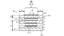
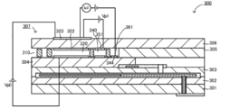
- FIG. 10 is a schematic cross-sectional view schematically showing an example of the configuration of such a conventional gas sensor 300.
- the gas sensor 300 includes a sensor element 307.
- This sensor element 307 is an element having a structure in which dense oxygen ion conductive solid electrolyte layers 301 to 306 are laminated.
- a measurement gas circulation part for introducing a measurement gas is formed between the lower surface of the solid electrolyte layer 306 and the upper surface of the solid electrolyte layer 304.
- An introduction part 310 and first to third internal spaces 320, 340, 361 are provided.
- An inner pump electrode 322 is formed in the first internal space 320, an auxiliary pump electrode 351 is formed in the second internal space 340, and a measurement electrode 344 is formed in the third internal space 361. ing.
- An outer pump electrode 323 is formed on the upper surface of the solid electrolyte layer 306.
- the control voltage Vp1 applied between the outer pump electrode 323 and the auxiliary pump electrode 351 causes the second internal space 340 and the sensor element 307 to move. Oxygen is pumped out or pumped in from the outside. In this way, the gas to be measured after the oxygen concentration is controlled while passing through the first internal space 320 and the second internal space 340 is introduced into the third internal space 361.
- the specific gas concentration in the gas to be measured is detected based on the current Ip2 when oxygen is pumped out or pumped in via the outer pump electrode 323 and the measurement electrode 344.
- JP 2006-284223 A JP 2011-102797 PR
- the movement of oxygen ions may occur even in a portion where the electrode is not formed and the solid electrolyte is exposed on the outer surface of the laminate (sensor element) of the solid electrolyte layer.
- no electrode is interposed between the atmosphere (measurement gas) immediately above the third internal space 361 on the upper surface of the solid electrolyte layer 306 and the inside of the third internal space 361.
- oxygen ions may pass through the solid electrolyte layer 306.
- Such movement of oxygen ions not via the electrode is more likely to occur at higher temperatures or as the difference in oxygen concentration inside and outside the sensor element increases.
- the movement accuracy of the oxygen ions may reduce the detection accuracy of the specific gas concentration in the gas to be measured.
- the detection accuracy of the specific gas concentration may be reduced. Since the current used for detecting the specific gas concentration like the current Ip2 is often a very small amount of current, it is easily affected by the movement of oxygen ions not through the electrode.
- the present invention has been made in view of the above-described problems, and it is a main object of the present invention to suppress the movement of oxygen ions between the measurement electrode installation space and the outside of the laminated body without using an electrode in the sensor element.
- the present invention employs the following means in order to achieve the above-described object.
- the sensor element of the present invention is A laminate in which a plurality of oxygen ion conductive solid electrolyte layers are laminated, and a measurement gas circulation part for introducing a measurement gas from one end is provided inside, A measurement electrode formed exposed to a measurement electrode installation space that is a part of the measured gas flow part; An outer electrode disposed on the outer surface of the laminate; An inner blocking layer that is formed so as to cover at least a part of the exposed portion of the solid electrolyte layer in the inner peripheral surface of the measurement electrode installation space and does not have conductivity of one or more substances among substances containing oxygen.
- a blocking portion having at least one of an outer blocking layer having no conductivity of one or more substances; It is equipped with.
- This sensor element includes an inner blocking layer formed so as to cover at least a part of the exposed portion of the solid electrolyte layer in the inner peripheral surface of the measurement electrode installation space, and an exposed portion of the solid electrolyte layer on the outer surface of the laminate.
- a blocking portion having at least one of an outer blocking layer formed so as to cover at least a part of the closest portion having the smallest distance from the measurement electrode installation space is provided.
- the inner blocking layer and the outer blocking layer do not have the conductivity (also referred to as conductivity) of one or more types of substances including oxygen. By doing so, the movement of oxygen ions is suppressed in the portion covered with the blocking portion in the exposed portion of the solid electrolyte layer.
- the influence on the current between the measurement electrode and the outer electrode based on the movement of oxygen ions not through the electrode can be suppressed, and the specific gas in the gas to be measured can be suppressed.
- the detection accuracy of the gas concentration can be further improved. Note that the smaller the distance between the measurement electrode installation space and the outside of the laminate, the easier the movement of oxygen ions between the measurement electrode installation space and the outside of the laminate without passing through the electrodes.
- the outer blocking layer is formed so as to cover at least a part of the closest approach portion, so that the movement of oxygen ions without passing through the electrode is more reliably performed. So that it can be suppressed.
- the “substance containing oxygen” includes oxygen (O) in a chemical formula in addition to a molecule containing oxygen (O) in a chemical formula such as O 2 , CO, CO 2 , NOx, and H 2 O.
- Including ions includes, for example, oxygen ions (also referred to as oxide ions) such as O 2 ⁇ and O 2 ⁇ .
- the inner blocking layer and the outer blocking layer may not have conductivity of one or more kinds of molecules including oxygen, or may have conductivity of one or more kinds of ions including oxygen.
- the inner blocking layer and the outer blocking layer may be different in the kind of the material having no conductivity, or may be the same. Note that when a substance such as an oxygen-containing molecule or oxygen-containing ion (other than oxygen ions) reaches the surface of the solid electrolyte layer, oxygen ions may be generated from the substance and move in the solid electrolyte.
- the blocking layer (the inner blocking layer or the outer blocking layer) is not limited to the one having no conductivity of oxygen ions, the oxygen ion migration described above may be used as long as it does not have the conductivity of a substance containing oxygen. The effect which suppresses is acquired.
- a blocking part does not have the conductivity of 1 or more types of the substance which exists in to-be-measured gas among the substances containing oxygen. By so doing, it is possible to more reliably suppress the movement of oxygen ions not via the electrode.
- the blocking portion has a higher ability to block the gas to be measured (including not only the component of the gas to be measured but also the component of the gas to be ionized) and the surface of the solid electrolyte.
- the porosity of the blocking portion is preferably 8% or less, and more preferably 5% or less.
- the blocking portion may include the outer blocking layer, and the outer blocking layer may cover the entire closest portion.
- the area ratio A / B between the covering area A where the blocking portion covers the solid electrolyte layer and the exposed area B of the solid electrolyte layer in the inner peripheral surface of the measurement electrode installation space is 0. It is good also as 3 or more. If it carries out like this, the effect which a prevention part will suppress the movement of the oxygen ion which does not go through an electrode will increase more.
- the area ratio A / B is more preferably 0.5 or more. The effect of suppressing the movement of oxygen ions not through the electrode increases as the area ratio A / B increases.
- the covering area A is the sum of the area where the outer blocking layer covers the solid electrolyte layer and the area where the inner blocking layer covers the solid electrolyte layer. It is.
- the exposed area B is a value including the area of the portion covered with the inner blocking layer.
- the area which an outer side prevention layer covers a solid electrolyte layer is more than the area which a measurement electrode covers a solid electrolyte layer.
- the area where the inner blocking layer covers the solid electrolyte layer is preferably equal to or larger than the area where the measurement electrode covers the solid electrolyte layer.
- the blocking portion includes the inner blocking layer, and the inner blocking layer preferably has a thickness of 1 ⁇ m to 30 ⁇ m.
- the thickness of the inner blocking layer is preferably 1 ⁇ m to 30 ⁇ m.
- the blocking portion includes the inner blocking layer, and the inner blocking layer is at least a part of a portion of the inner peripheral surface of the measurement electrode installation space that faces the closest portion. May be covered.
- the closer the distance between the measurement electrode installation space and the outside of the laminate the easier the oxygen ions move between the measurement electrode installation space and the outside of the laminate, so the closest approach is possible.
- the inner blocking layer covers at least a part of the part facing the part, it is possible to further suppress the movement of oxygen ions not through the electrode.
- the "part facing the closest part of the inner peripheral surface of the measurement electrode installation space” may be, for example, a part opposite to the closest part via the solid electrolyte layer, It is good also as a part which projected this closest part to the inner peripheral surface of the said measurement electrode installation space perpendicular
- the said inner side prevention layer is good also as what covers all the parts which oppose the said closest approach part among the internal peripheral surfaces of the said measurement electrode installation space. In this way, the effect of suppressing the movement of oxygen ions not through the electrode is further enhanced.
- the blocking portion may include the inner blocking layer and the outer blocking layer.
- the effect of suppressing the movement of oxygen ions not through the electrode is further enhanced as compared with the case where the blocking layer has only one of the inner blocking layer and the outer blocking layer.
- the stacked body is a rectangular parallelepiped
- the blocking portion includes the outer blocking layer
- the outer blocking layer is formed on a plurality of outer surfaces of the stacked body.
- the layer may cover all the projection areas in which the measurement electrode installation space is projected in the vertical direction with respect to each of the plurality of outer surfaces on which the outer blocking layer is formed.
- the projection area obtained by projecting the measurement electrode installation space in the vertical direction on each outer surface is the area of the outer surface having the smallest distance from the measurement electrode installation space. . Therefore, when forming the outer blocking layer on a plurality of outer surfaces, the outer surface on which the outer blocking layer is formed covers the entire projection region, thereby suppressing the movement of oxygen ions not through the electrode. Can be increased.
- the gas sensor according to the present invention includes the sensor element according to any one of the above-described aspects. Therefore, the gas sensor of the present invention suppresses the same effect as that of the sensor element of the present invention, for example, the influence on the current between the measurement electrode and the outer electrode based on the movement of oxygen ions without passing through the electrode, so The effect of further improving the detection accuracy of the specific gas concentration can be obtained.
- a first internal space and a second internal space are formed in this order in the measured gas flow section from the measured gas introduction port to the measurement electrode installation space.
- a reference electrode that is formed inside the stack and into which a reference gas serving as a reference for detecting a specific gas concentration in the measurement gas is introduced, and the measurement gas is introduced into the measurement electrode installation space,
- the first A main pump cell for pumping or pumping oxygen through the inner main pump electrode and the outer main pump electrode so that the oxygen concentration in the partial space becomes a predetermined main pump target concentration; and a surface facing the second internal space
- An outer auxiliary pump electrode disposed on the outer surface of the laminate and the inner auxiliary pump electrode based on an electromotive force generated between the inner auxiliary pump electrode formed on the solid electrolyte layer and the reference electrode.
- a control voltage is applied between the inner auxiliary pump electrode and the outer auxiliary pump electrode so that the oxygen concentration in the second internal space becomes a predetermined auxiliary pump target concentration. It is good also as what was equipped with the auxiliary pump cell to perform.
- the oxygen concentration in the gas to be measured is adjusted to a predetermined main pump target concentration, and further, the gas to be measured passes through the second internal space.
- the oxygen concentration in the measurement gas is adjusted to a predetermined auxiliary pump target concentration, the oxygen concentration of the measurement gas reaching the measurement electrode installation space can be kept constant with high accuracy. Thereby, the detection accuracy of the specific gas concentration in the gas to be measured can be further improved.
- FIG. 2 is a schematic cross-sectional view of a gas sensor 100.
- FIG. FIG. 2 is a cross-sectional view taken along the line AA in FIG.
- FIG. 3 is a B view of FIG. 2.
- It is a perspective view of the gas sensor 100 of a modification.
- It is a cross-sectional schematic diagram of the gas sensor 100 of the modification.
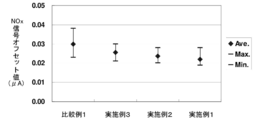
- 6 is a graph showing NOx signal offset values of Examples 1 to 3 and Comparative Example 1;
- 5 is a graph showing NOx signal offset values of Examples 1, 4, 5 and Comparative Example 2.
- It is a graph which shows the boundary line from which the NOx signal offset value becomes favorable when the thickness and porosity of the blocking part 65 are variously changed.
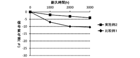
- 5 is a graph showing a signal change rate of Example 2 and Comparative Example 1.
- It is a cross-sectional schematic diagram of the gas sensor 300 of a prior art example.
- FIG. 1 is a schematic cross-sectional view schematically showing an example of the configuration of the gas sensor 100.
- the gas sensor 100 includes a sensor element 101 that detects the NOx concentration in the gas to be measured.
- the sensor element 101 includes a first substrate layer 1, a second substrate layer 2, a third substrate layer 3, and a first solid electrolyte layer 4 each made of an oxygen ion conductive solid electrolyte layer such as zirconia (ZrO 2 ).
- the six layers of the spacer layer 5 and the second solid electrolyte layer 6 are elements having a laminate in which the layers are laminated in this order from the bottom in the drawing.
- the solid electrolyte forming these six layers is dense and airtight.
- the sensor element 101 is manufactured, for example, by performing predetermined processing and circuit pattern printing on a ceramic green sheet corresponding to each layer, stacking them, and firing and integrating them.
- a buffer space 12 a second diffusion rate limiting unit 13, a first internal space 20, a third diffusion rate limiting unit 30, a second internal space 40, a fourth diffusion rate limiting unit 60, and a third internal
- the void 61 is formed adjacent to each other in such a manner that it communicates in this order.
- the gas introduction port 10, the buffer space 12, the first internal space 20, the second internal space 40, and the third internal space 61 are provided with upper portions provided in a manner in which the spacer layer 5 is hollowed out.
- a space inside the sensor element 101 is defined by the lower surface of the second solid electrolyte layer 6, the lower portion being the upper surface of the first solid electrolyte layer 4, and the side portions being the side surfaces of the spacer layer 5.
- the first diffusion rate limiting unit 11, the second diffusion rate limiting unit 13, the third diffusion rate limiting unit 30, and the fourth diffusion rate limiting unit 60 are all two horizontally long (the openings are long in the direction perpendicular to the drawing). Provided as a slit).
- part from the gas inlet 10 to the 3rd internal space 61 is also called a to-be-measured gas distribution
- a reference gas introduction space 43 is provided at a partitioned position.
- the atmosphere is introduced into the reference gas introduction space 43 as a reference gas when measuring the NOx concentration.
- the air introduction layer 48 is a layer made of porous alumina and exposed to the reference gas introduction space 43.
- a reference gas is introduced into the atmosphere introduction layer 48 through a reference gas introduction space 43.
- the air introduction layer 48 is formed so as to cover the reference electrode 42.
- the atmosphere introduction layer 48 introduces the reference gas in the reference gas introduction space 43 to the reference electrode 42 while giving a predetermined diffusion resistance to the reference gas.
- the atmosphere introduction layer 48 is formed so as to be exposed to the reference gas introduction space 43 only on the other end side (right side in FIG. 1) of the sensor element 101 with respect to the reference electrode 42. Therefore, for example, the path of the reference gas from the reference gas introduction space 43 to the reference electrode 42 becomes longer than in the case where the reference gas introduction space 43 is formed right above the reference electrode 42 in FIG.
- the atmospheric introduction layer 48 makes it easy to give a predetermined high diffusion resistance to the reference gas.
- the higher the diffusion resistance applied to the reference gas the smaller the amount of oxygen contained in the reference gas that reaches the reference electrode 42. Therefore, by applying a predetermined high diffusion resistance, when measuring the oxygen concentration (oxygen partial pressure) in the measured gas flow section using the reference electrode 42, a slight change in oxygen concentration in the measured gas flow section is observed. It becomes easy to detect and detection sensitivity can be improved.
- the reference gas introduction space 43 is formed up to just above the reference electrode 42 in FIG. 1, the reference electrode 42 is easily poisoned by the reference gas, but this embodiment prevents this. can do.
- the reference electrode 42 may be formed immediately below the reference gas introduction space 43 in FIG.
- the reference electrode 42 is an electrode formed in such a manner that it is sandwiched between the upper surface of the third substrate layer 3 and the first solid electrolyte layer 4. As described above, the reference electrode 42 leads to the reference gas introduction space 43. An air introduction layer 48 is provided. The reference electrode 42 is formed directly on the upper surface of the third substrate layer 3, and the portion other than the portion in contact with the upper surface of the third substrate layer 3 is covered with the air introduction layer 48. Further, as will be described later, it is possible to measure the oxygen concentration (oxygen partial pressure) in the first internal space 20, the second internal space 40, and the third internal space 61 using the reference electrode 42. It has become.
- the gas inlet 10 is a part opened to the external space, and the measured gas is taken into the sensor element 101 from the outer space through the gas inlet 10. Yes.
- the first diffusion control unit 11 is a part that provides a predetermined diffusion resistance to the gas to be measured taken from the gas inlet 10.
- the buffer space 12 is a space provided to guide the gas to be measured introduced from the first diffusion rate controlling unit 11 to the second diffusion rate controlling unit 13.
- the second diffusion rate limiting unit 13 is a part that imparts a predetermined diffusion resistance to the gas to be measured introduced from the buffer space 12 into the first internal space 20.
- the pressure fluctuation of the gas to be measured in the external space exhaust pressure pulsation if the gas to be measured is an automobile exhaust gas
- the gas to be measured that is suddenly taken into the sensor element 101 from the gas inlet 10 is not directly introduced into the first internal space 20, but the first diffusion control unit 11, the buffer space 12, the second After the concentration variation of the gas to be measured is canceled through the diffusion control unit 13, the gas is introduced into the first internal space 20.
- the first internal space 20 is provided as a space for adjusting the partial pressure of oxygen in the gas to be measured introduced through the second diffusion rate limiting unit 13. The oxygen partial pressure is adjusted by the operation of the main pump cell 21.
- the main pump cell 21 includes an inner pump electrode 22 having a ceiling electrode portion 22a provided on substantially the entire lower surface of the second solid electrolyte layer 6 facing the first internal space 20, and an upper surface of the second solid electrolyte layer 6.
- An electrochemical pump cell comprising an outer pump electrode 23 provided in a manner exposed to the external space in a region corresponding to the ceiling electrode portion 22a, and a second solid electrolyte layer 6 sandwiched between these electrodes. is there.
- the inner pump electrode 22 is formed across the upper and lower solid electrolyte layers (the second solid electrolyte layer 6 and the first solid electrolyte layer 4) that define the first inner space 20, and the spacer layer 5 that provides side walls. Yes. Specifically, a ceiling electrode portion 22a is formed on the lower surface of the second solid electrolyte layer 6 that provides the ceiling surface of the first internal space 20, and a bottom portion is formed on the upper surface of the first solid electrolyte layer 4 that provides the bottom surface.
- the electrode portions 22b are formed directly, and the side electrode portions (not shown) constitute both side walls of the first internal space 20 so as to connect the ceiling electrode portions 22a and the bottom electrode portions 22b. It is formed on the side wall surface (inner surface) of the spacer layer 5 and is disposed in a tunnel-shaped structure at the portion where the side electrode portion is disposed.
- the inner pump electrode 22 and the outer pump electrode 23 are formed as a porous cermet electrode (for example, a cermet electrode of Pt and ZrO 2 containing 1% of Au).
- the inner pump electrode 22 in contact with the gas to be measured is formed using a material that has a reduced reduction ability for the NOx component in the gas to be measured.
- a desired pump voltage Vp 0 is applied between the inner pump electrode 22 and the outer pump electrode 23, and the pump current is positive or negative between the inner pump electrode 22 and the outer pump electrode 23.
- Ip0 oxygen in the first internal space 20 can be pumped into the external space, or oxygen in the external space can be pumped into the first internal space 20.
- the reference electrode 42 constitutes an electrochemical sensor cell, that is, a main pump control oxygen partial pressure detection sensor cell 80.
- the oxygen concentration (oxygen partial pressure) in the first internal space 20 can be known by measuring the electromotive force V0 in the oxygen partial pressure detection sensor cell 80 for main pump control. Further, the pump current Ip0 is controlled by feedback-controlling the pump voltage Vp0 of the variable power source 25 so that the electromotive force V0 is constant. Thereby, the oxygen concentration in the first internal space 20 can be kept at a predetermined constant value.
- the third diffusion control unit 30 provides a predetermined diffusion resistance to the gas under measurement whose oxygen concentration (oxygen partial pressure) is controlled by the operation of the main pump cell 21 in the first internal space 20, and the gas under measurement is supplied to the gas under measurement. This is the part that leads to the second internal space 40.
- the auxiliary pump cell 50 is further supplied to the gas to be measured introduced through the third diffusion rate limiting unit 30. It is provided as a space for adjusting the oxygen partial pressure. Thereby, since the oxygen concentration in the second internal space 40 can be kept constant with high accuracy, the gas sensor 100 can measure the NOx concentration with high accuracy.
- the auxiliary pump cell 50 includes an auxiliary pump electrode 51 having a ceiling electrode portion 51a provided on substantially the entire lower surface of the second solid electrolyte layer 6 facing the second internal space 40, and an outer pump electrode 23 (outer pump electrode 23).
- the auxiliary electrochemical pump cell is configured by the second solid electrolyte layer 6 and a suitable electrode outside the sensor element 101 is sufficient.
- the auxiliary pump electrode 51 is disposed in the second internal space 40 in the same tunnel structure as the inner pump electrode 22 provided in the first internal space 20. That is, the ceiling electrode portion 51 a is formed on the second solid electrolyte layer 6 that provides the ceiling surface of the second internal space 40, and the top surface of the first solid electrolyte layer 4 that provides the bottom surface of the second internal space 40.
- the bottom electrode part 51b is formed directly, and the side electrode part (not shown) connecting the ceiling electrode part 51a and the bottom electrode part 51b provides the side wall of the second internal space 40.
- the tunnel structure is formed on both wall surfaces of the spacer layer 5. Note that the auxiliary pump electrode 51 is also formed using a material having a reduced reducing ability with respect to the NOx component in the gas to be measured, like the inner pump electrode 22.
- auxiliary pump cell 50 by applying a desired voltage Vp1 between the auxiliary pump electrode 51 and the outer pump electrode 23, oxygen in the atmosphere in the second internal space 40 is pumped to the external space, or It is possible to pump into the second internal space 40 from the space.
- the layer 4 constitutes an electrochemical sensor cell, that is, an auxiliary pump control oxygen partial pressure detection sensor cell 81.
- the auxiliary pump cell 50 performs pumping by the variable power source 52 that is voltage-controlled based on the electromotive force V1 detected by the auxiliary pump control oxygen partial pressure detection sensor cell 81. Thereby, the oxygen partial pressure in the atmosphere in the second internal space 40 is controlled to a low partial pressure that does not substantially affect the measurement of NOx.
- the pump current Ip1 is used for controlling the electromotive force of the oxygen partial pressure detection sensor cell 80 for main pump control. Specifically, the pump current Ip1 is input as a control signal to the main pump control oxygen partial pressure detection sensor cell 80, and the electromotive force V0 is controlled, so that the third diffusion rate limiting unit 30 controls the second internal space.
- the gradient of the oxygen partial pressure in the gas to be measured introduced into the gas 40 is controlled so as to be always constant.
- the oxygen concentration in the second internal space 40 is maintained at a constant value of about 0.001 ppm by the action of the main pump cell 21 and the auxiliary pump cell 50.
- the fourth diffusion control unit 60 gives a predetermined diffusion resistance to the gas to be measured whose oxygen concentration (oxygen partial pressure) is controlled by the operation of the auxiliary pump cell 50 in the second internal space 40, and causes the gas to be measured to flow. This is the part that leads to the third internal space 61.
- the fourth diffusion control unit 60 plays a role of limiting the amount of NOx flowing into the third internal space 61.
- the third internal space 61 is in the gas to be measured with respect to the gas to be measured introduced through the fourth diffusion rate limiting unit 60 after the oxygen concentration (oxygen partial pressure) has been adjusted in the second internal space 40 in advance. It is provided as a space for performing processing related to the measurement of the nitrogen oxide (NOx) concentration.
- the NOx concentration is measured mainly by the operation of the measurement pump cell 41 in the third internal space 61.
- the measurement pump cell 41 measures the NOx concentration in the gas to be measured in the third internal space 61.
- the measurement pump cell 41 includes a measurement electrode 44 provided directly on the upper surface of the first solid electrolyte layer 4 facing the third internal space 61, the outer pump electrode 23, the second solid electrolyte layer 6, and a spacer layer. 5 and an electrochemical pump cell constituted by the first solid electrolyte layer 4.
- the measurement electrode 44 is a porous cermet electrode.
- the measurement electrode 44 also functions as a NOx reduction catalyst that reduces NOx present in the atmosphere in the third internal space 61.
- oxygen generated by the decomposition of nitrogen oxides in the atmosphere around the measurement electrode 44 can be pumped out, and the generated amount can be detected as the pump current Ip2.
- the measurement electrode 44 in order to detect the oxygen partial pressure around the measurement electrode 44, the first solid electrolyte layer 4, the measurement electrode 44, and the reference electrode 42 are used to provide an electrochemical sensor cell, that is, a measurement pump control oxygen component.
- a pressure detection sensor cell 82 is configured.
- the variable power supply 46 is controlled on the basis of the electromotive force V2 detected by the measurement pump control oxygen partial pressure detection sensor cell 82.
- the gas to be measured introduced into the second internal space 40 reaches the measurement electrode 44 of the third internal space 61 through the fourth diffusion rate-determining unit 45 under the condition where the oxygen partial pressure is controlled.
- Nitrogen oxide in the gas to be measured around the measurement electrode 44 is reduced (2NO ⁇ N 2 + O 2 ) to generate oxygen.
- the generated oxygen is pumped by the measurement pump cell 41.
- the variable power source is set so that the control voltage V2 detected by the measurement pump control oxygen partial pressure detection sensor cell 82 becomes constant. 46 voltage Vp2 is controlled. Since the amount of oxygen generated around the measurement electrode 44 is proportional to the concentration of nitrogen oxide in the gas to be measured, the nitrogen oxide in the gas to be measured using the pump current Ip2 in the measurement pump cell 41. The concentration will be calculated.
- the measurement electrode 44, the first solid electrolyte layer 4, the third substrate layer 3, and the reference electrode 42 are combined to form an oxygen partial pressure detecting means as an electrochemical sensor cell, the measurement electrode
- the electromotive force according to the difference between the amount of oxygen generated by the reduction of the NOx component in the atmosphere around 44 and the amount of oxygen contained in the reference atmosphere can be detected, whereby the NOx component in the gas to be measured It is also possible to determine the concentration of.
- the second solid electrolyte layer 6, the spacer layer 5, the first solid electrolyte layer 4, the outer pump electrode 23, and the reference electrode 42 constitute an electrochemical sensor cell 83.
- the oxygen partial pressure in the gas to be measured outside the sensor can be detected by the obtained electromotive force Vref.
- the oxygen partial pressure is always kept at a constant low value (a value that does not substantially affect the measurement of NOx).
- a gas to be measured is supplied to the measurement pump cell 41. Therefore, the NOx concentration in the measurement gas is determined based on the pump current Ip2 that flows when oxygen generated by the reduction of NOx is pumped out of the measurement pump cell 41 in proportion to the NOx concentration in the measurement gas. You can know.
- the sensor element 101 includes a heater unit 70 that plays a role of temperature adjustment for heating and maintaining the sensor element 101 in order to increase the oxygen ion conductivity of the solid electrolyte.
- the heater unit 70 includes a heater electrode 71, a heater 72, a through hole 73, a heater insulating layer 74, a pressure dissipation hole 75, and a lead wire 76.
- the heater electrode 71 is an electrode formed so as to be in contact with the lower surface of the first substrate layer 1. By connecting the heater electrode 71 to an external power source, power can be supplied to the heater unit 70 from the outside.
- the heater 72 is an electrical resistor formed in a manner sandwiched between the second substrate layer 2 and the third substrate layer 3 from above and below.
- the heater 72 is connected to the heater electrode 71 through a lead wire 76 and a through hole 73, and generates heat when power is supplied from the outside through the heater electrode 71 to heat and keep the solid electrolyte forming the sensor element 101. I do.
- the heater 72 is embedded over the entire area from the first internal space 20 to the third internal space 61, and the entire sensor element 101 can be adjusted to a temperature at which the solid electrolyte is activated. ing.
- the heater insulating layer 74 is an insulating layer made of porous alumina formed by an insulator such as alumina on the upper and lower surfaces of the heater 72.
- the heater insulating layer 74 is formed for the purpose of obtaining electrical insulation between the second substrate layer 2 and the heater 72 and electrical insulation between the third substrate layer 3 and the heater 72.
- the pressure dissipating hole 75 is a portion that is provided so as to penetrate the third substrate layer 3 and communicate with the reference gas introduction space 43, and is for the purpose of alleviating the increase in internal pressure accompanying the temperature increase in the heater insulating layer 74. Formed.
- the sensor element 101 includes a blocking unit 65.
- the blocking portion 65 has an inner blocking layer 66 formed in the third inner space 61 and an outer blocking layer 67 formed on the upper surface of the second solid electrolyte layer 6 in FIG.
- the inner blocking layer 66 and the outer blocking layer 67 are for suppressing oxygen ions from moving through the laminate (second solid electrolyte layer 6) without passing through the electrodes such as the outer electrode 23 and the measurement electrode 44. is there.
- the inner blocking layer 66 and the outer blocking layer 67 do not have conductivity of one or more kinds of substances containing oxygen, such as alumina, quartz glass, soda glass, silica, mullite, silicon nitride, and carbonized. It is made of silicon or the like.
- the “substance containing oxygen” includes, for example, an ion containing oxygen (O) in a chemical formula not only in a molecule containing oxygen (O) in a chemical formula such as O 2 , CO, CO 2 , NOx, and H 2 O.
- the “ion containing oxygen” includes, for example, oxygen ions (also referred to as oxide ions) such as O 2 ⁇ and O 2 ⁇ .
- the inner blocking layer 66 and the outer blocking layer 67 increase the effect of suppressing the movement of oxygen ions not through the electrode. Therefore, the smaller the porosity and the larger the thickness, the better.
- the porosity of the blocking portion 65 is preferably 0% or more and 8% or less, and more preferably 5% or less.
- the thicknesses of the inner blocking layer 66 and the outer blocking layer 67 are preferably 1 ⁇ m to 30 ⁇ m. By setting the thickness to 1 ⁇ m or more, the effect of suppressing the movement of oxygen ions not through the electrode can be obtained more reliably.
- the inner blocking layer 66 and the outer blocking layer 67 can be formed relatively easily on the solid electrolyte layer.
- the inner blocking layer 66 and the outer blocking layer 67 may be made of the same material or different materials. Further, the porosity and thickness may be the same or different.
- FIG. 2 is a cross-sectional view taken along the line AA in FIG. 1
- FIG. 3 is a view as seen from B in FIG.
- the inner blocking layer 66 is formed so as to cover at least a part of the exposed portion of the solid electrolyte layer (the first and second solid electrolyte layers 4 and 6 and the spacer layer 5) on the inner peripheral surface of the third inner space 61.
- the outer blocking layer 67 is formed to face the inner blocking layer 66 on the upper surface of FIG. 1 that is one of the outer surfaces of the second solid electrolyte layer 6.
- the outer blocking layer 67 covers the entire closest portion 6a of the second solid electrolyte layer 6 having the smallest distance from the third internal space 61 among the exposed portion of the solid electrolyte layer on the outer surface of the sensor element 101. It is formed so as to cover the periphery of the closest part 6a.
- the sensor element 101 is a rectangular parallelepiped
- the first surface 101a upper surface in FIG. 2
- the second surface 101b lower surface in FIG. 2
- the third surface 101c in FIG. 2 are used as outer surfaces of the sensor element 101.
- the left side surface, the fourth surface 101d (right side surface in FIG. 2), the fifth surface 101e (left end surface in FIG. 3), and the sixth surface 101f (right end surface in FIG. 3).
- the distances from the third internal space 61 to the first surface to the sixth surfaces 101a to 101f are distances X1 to X6, respectively, the distance X1 from the third internal space 61 to the first surface 101a is It is formed to be the smallest. Therefore, an outer blocking layer 67 is formed so as to cover the closest part 6a with the part of the first surface 101a having the smallest distance from the third internal space 61 as the closest part 6a.
- the closest part 6a is also a projection surface when the third internal space 61 is projected perpendicularly to the first surface 101a.
- the inner blocking layer 66 is a portion of the inner peripheral surface of the third internal space 61 that faces the closest portion 6a (that is, the lower surface of the second solid electrolyte layer 6 that is the ceiling surface of the third internal space 61). It covers almost the whole. In other words, the projection surface when the inner blocking layer 66 is projected perpendicularly to the first surface 101a substantially coincides with the closest portion 6a.
- the blocking portion 65 has an area ratio A / B between the covering area A where the blocking portion 65 covers the solid electrolyte layer and the exposed area B of the solid electrolyte layer in the inner peripheral surface of the third internal space 61 being 0.00. It is formed to be 3 or more.
- the covering area A where the blocking portion 65 covers the solid electrolyte layer is the sum of the area where the inner blocking layer 66 covers the solid electrolyte layer and the area where the outer blocking layer 67 covers the solid electrolyte layer.
- the exposed area B is a value including the area of the portion covered with the inner blocking layer 66. That is, the exposed area B is an exposed area of the solid electrolyte layer in the inner peripheral surface of the third internal space 61 when the inner blocking layer 66 is ignored.
- the inner blocking layer 66 and the measurement electrode 44 are formed in the third internal space 61, the measurement electrode among the inner peripheral surfaces (six surfaces) of the third internal space 61.
- the area of the portion not covered with 44 is the exposed area B.
- the area ratio A / B is more preferably 0.5 or more.
- the area where the inner blocking layer 66 covers the solid electrolyte layer is preferably equal to or larger than the area where the measurement electrode 44 covers the solid electrolyte layer.
- the area where the outer blocking layer 67 covers the solid electrolyte layer is also preferably equal to or larger than the area where the measurement electrode 44 covers the solid electrolyte layer.
- the sensor element 101 of the gas sensor 100 will be described below.
- six green ceramic green sheets containing an oxygen ion conductive solid electrolyte such as zirconia as a ceramic component are prepared.
- a plurality of sheet holes and necessary through holes used for positioning during printing and lamination are formed in advance.
- a space serving as a measured gas circulation part is provided in advance in the green sheet that becomes the spacer layer 5 by a punching process or the like.
- a space that becomes the reference gas introduction space 43 is also provided in the green sheet that becomes the first solid electrolyte layer 4.
- Pattern printing and drying are performed to form various patterns on the ceramic green sheet.
- the pattern to be formed is, for example, a pattern of each of the electrodes and lead wires described above, the air introduction layer 48, the heater unit 70, the blocking unit 65, and the like.
- Pattern printing is performed by applying a pattern forming paste prepared according to the characteristics required for each object to be formed on a green sheet using a known screen printing technique.
- the drying process is also performed using a known drying means.
- the laminated body thus obtained includes a plurality of sensor elements 101.
- the laminated body is cut and cut into the size of the sensor element 101.
- the cut laminate is fired at a predetermined firing temperature to obtain the sensor element 101.
- the gas sensor 100 is obtained by being housed in a predetermined housing and incorporated in the main body (not shown) of the gas sensor 100.
- the inner blocking layer 66 and the outer blocking layer 67 of the sensor element 101 do not have one or more types of conductivity among substances containing oxygen, so that the inner blocking layer 66 out of the surface of the laminate. Further, the movement of oxygen ions is suppressed in the portion covered with the outer blocking layer 67.
- the portion of the surface of the stacked body covered by the outer blocking layer 67 has oxygen ions between the outside and the inside of the stacked body. Movement is suppressed.
- the inner blocking layer 66 does not have oxygen ion conductivity
- the portion of the surface of the stack that is covered with the inner blocking layer 66 is between the third internal space 61 and the stack.
- the movement of oxygen ions is suppressed. Further, not only in the case of not having oxygen ion conductivity, if the inner blocking layer 66 and the outer blocking layer 67 do not have at least one conductivity of a substance containing oxygen, the movement of oxygen ions is similarly performed. The effect of suppressing is acquired. This is because when a substance containing oxygen other than oxygen ions reaches the surface of the laminate, oxygen ions may be generated from this substance, which can be suppressed. As described above, by having the inner blocking layer 66 and the outer blocking layer 67, oxygen ions are not generated between the third inner space 61 and the outside of the laminate without using the electrodes such as the measurement electrode 44 and the outer pump electrode 23. Is restrained from moving.
- the first substrate layer 1, the second substrate layer 2, the third substrate layer 3, the first solid electrolyte layer 4, the spacer layer 5 and the second solid electrolyte layer 6 of the present embodiment correspond to the laminate of the present invention, and are measured.
- the electrode 44 corresponds to the measurement electrode
- the third internal space 61 corresponds to the measurement electrode installation space
- the outer pump electrode 23 corresponds to the outer electrode, the outer main pump electrode, and the outer auxiliary pump electrode
- the measurement pump cell 41
- the blocking part 65 having the inner blocking layer 66 and the outer blocking layer 67 corresponds to the blocking part.
- the reference electrode 42 corresponds to the reference electrode
- the inner pump electrode 22 corresponds to the inner main pump electrode
- the main pump cell 21 corresponds to the main pump cell
- the auxiliary pump electrode 51 corresponds to the inner auxiliary pump electrode
- the auxiliary pump cell. 50 corresponds to an auxiliary pump cell.
- an example of the gas sensor of the present invention is also clarified by describing the gas sensor 100 including the sensor element 101.
- the inner blocking layer 66 formed so as to cover at least a part of the exposed portion of the solid electrolyte layer in the inner peripheral surface of the third internal space 61;
- An outer blocking layer 67 formed so as to cover at least a part of the closest part 6a having the smallest distance from the third inner space 61 among the exposed part of the solid electrolyte layer on the outer surface of the laminate.
- a blocking unit 65 is provided.
- the inner blocking layer 66 and the outer blocking layer 67 do not have the conductivity of one or more types of substances including oxygen. By doing so, the movement of oxygen ions is suppressed in the portion of the exposed portion of the solid electrolyte layer covered with the blocking portion 65.
- the gas sensor 100 can detect the NOx concentration in the gas to be measured based on the pump current Ip2, but when noise occurs in the pump current Ip2, the pump current Ip2 accurately reflects the NOx concentration. The detection accuracy decreases.
- the gas sensor 100 of the present embodiment by suppressing the movement of oxygen ions not passing through such an electrode by the blocking unit 65, the influence on the pump current Ip2 can be suppressed, and the NOx concentration in the gas to be measured can be suppressed.
- the detection accuracy can be further improved.
- the outer blocking layer is covered so as to cover at least a part of the closest part 6a having the smallest distance from the third internal space 61 among the exposed part of the solid electrolyte layer on the outer surface of the laminate.
- the outer blocking layer 67 covers the entire closest portion 6a, the effect of the outer blocking layer 67 suppressing the movement of oxygen ions not through the electrode is further increased.
- the area ratio A / B between the covering area A where the blocking portion 65 covers the solid electrolyte layer and the exposed area B of the solid electrolyte layer in the inner peripheral surface of the third internal space 61 is 0.3 or more. Further, it is possible to further suppress the movement of oxygen ions not through the electrode.
- the porosity of the blocking portion 65 5% or less, it is possible to further suppress the movement of oxygen ions not through the electrode.
- the inner blocking layer 66 is a portion of the inner peripheral surface of the third inner space 61 that faces the closest portion 6a (a portion on the opposite side of the closest portion 6a via the second solid electrolyte layer 6). Covers the whole.
- the distance between the third internal space 61 and the outside of the stacked body is smaller, the movement of oxygen ions without intervening electrodes is more likely to occur. Therefore, the movement of oxygen ions that do not pass through the electrode can be further suppressed by covering the portion facing the closest portion 6a with the inner blocking layer.
- the blocking portion 65 has both the inner blocking layer 66 and the outer blocking layer 67, the effect of suppressing the movement of oxygen ions not passing through the electrode is further enhanced as compared with the case of having only one.
- the first internal space 20, the second internal space 40, and the third internal space 61 are formed in the measured gas circulation part, and the main pump cell is passed when the measured gas passes through the first internal space.
- 21 adjusts the oxygen concentration in the measured gas to a predetermined main pump target concentration
- the auxiliary pump cell 50 sets the oxygen concentration in the measured gas to a predetermined auxiliary Adjust to pump target concentration. For this reason, the oxygen concentration of the gas to be measured that reaches the third internal space 61 can be kept constant with high accuracy. Thereby, the detection accuracy of the specific gas concentration in the gas to be measured can be further improved.
- the blocking portion 65 includes both the inner blocking layer 66 and the outer blocking layer 67, but may include only one of them. Even in this case, the movement of oxygen ions that do not pass through the electrode can be suppressed by one of the inner blocking layer 66 and the outer blocking layer 67.
- the inner blocking layer 66 covers the entire surface of the inner peripheral surface of the third internal space 61 that faces the closest part 6a. It is good also as what covers at least one part. Further, the inner blocking layer 66 may cover the inner peripheral surface of the third internal space 61 other than the portion facing the closest portion 6 a, or the innermost surface of the third internal space 61 may be covered with the innermost surface. It is good also as what the inner side blocking layer 66 covers only except the part which opposes the approach part 6a. However, in order to enhance the effect of suppressing the movement of oxygen ions not passing through the electrode, it is preferable that the inner blocking layer 66 covers at least a part of the portion facing the closest portion 6a.
- the inner blocking layer 66 does not need to cover a portion of the inner peripheral surface of the third inner space 61 where the solid electrolyte layer is not exposed.
- the closest part except for such a part What is necessary is just to cover a part or all of the part which opposes the part 6a.
- the outer blocking layer 67 does not need to cover a portion where the solid electrolyte layer is not exposed, and preferably does not cover a portion where an electrode such as the outer pump electrode 23 is formed.
- the outer blocking layer 67 covers the entire closest portion 6a and further covers the periphery thereof, but is not limited thereto.
- an outer blocking layer that covers a portion of the first surface 101a away from the outer blocking layer 67 shown in FIGS. 1 to 3 may be further provided.
- the outer blocking layer 67 may cover only the entire closest part 6a, or may cover at least a part of the closest part 6a.
- the outermost blocking layer 67 covers the entire closest portion 6a.
- the outer blocking layer 67 may cover one or more surfaces other than the first surface 101a where the closest part 6a exists. In FIG.
- FIG. 4 the perspective view of the gas sensor 100 of a modification is shown.
- an outer blocking layer 67d that covers a part of the fourth surface 101d is further provided.
- the outer blocking layer 67d is formed so as to cover the entire projection area 6d when the third inner space 61 is projected perpendicularly to the fourth surface 101d, and further to cover the periphery thereof.
- each of the plurality of outer surfaces on which the outer blocking layer is formed covers all of the projection areas (the closest part 6a and the projection area 6d in FIG. 4) obtained by projecting the third internal space 61 in the vertical direction with respect to the first face 101a and the fourth face 101d). It is preferable. In this way, each of the plurality of outer surfaces on which the outer blocking layer is formed can cover the region (projection region) having the smallest distance from the third inner space 61 in the outer surface. The effect of suppressing the movement of oxygen ions that do not intervene can be further enhanced.
- the distance X1 is the shortest of the distances X1 to X6 shown in FIGS. 2 and 3, but the present invention is not limited to this.
- the distance X4 may be the minimum.
- the outer blocking layer may be formed so as to cover at least a part of the projection region 6d.
- both the projection area and the projection area 6d when the third internal space 61 is projected perpendicularly onto the third surface 101c are both.
- the outer blocking layer may be formed so as to cover at least a part of at least one of these.
- the “closest part” is a part having the smallest distance from the third internal space 61 “of the exposed part of the solid electrolyte layer” on the outer surface of the sensor element 101. Therefore, for example, when an electrode is formed at the same position as the outer blocking layer 67 in FIGS. 2 and 3, the portion of the first surface 101 a covered with the electrode is “exposed solid electrolyte layer”. Since it is not a “part”, the part is not the closest part.
- the exposed portion around the electrode becomes the closest portion.
- the portion where the solid electrolyte layer does not exist on the surface, such as the gas inlet 10 is not regarded as the closest portion.
- the main pump cell 21 is configured by the outer pump electrode 23, the inner pump electrode 22, and the second solid electrolyte layer 6, but instead of the outer pump electrode 23, the sensor element 101 is used.
- Another electrode (outer main pump electrode) provided outside the electrode may be used.
- the auxiliary pump cell 50 is configured by the auxiliary pump electrode 51, the outer pump electrode 23, and the second solid electrolyte layer 6.
- the auxiliary pump cell 50 is formed outside the sensor element 101. You may use the other electrode (henceforth an outside auxiliary pump electrode) provided.
- the inner pump electrode 22 is a tunnel-shaped electrode including the ceiling electrode portion 22a, the bottom electrode portion 22b, and the side electrode portion.
- the inner pump electrode 22 may be formed only of the ceiling electrode portion 22a or the bottom electrode portion. It is not limited to the tunnel form, for example, only 22b.
- the auxiliary pump electrode 51 is not limited to the tunnel form.
- the sensor element 101 of the gas sensor 100 includes the first internal space 20, the second internal space 40, and the third internal space 61, but is not limited thereto.
- the second internal space 40 may not be provided.
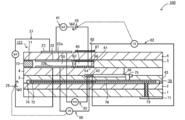
- a schematic cross-sectional view of a modified gas sensor 100 in this case is shown in FIG.
- the gas sensor 100 of this modified example between the lower surface of the second solid electrolyte layer 6 and the upper surface of the first solid electrolyte layer 4, a gas inlet 10, a first diffusion rate controlling part 11, The first internal space 20, the fourth diffusion rate controlling portion 60, and the third internal space 61 are formed adjacent to each other in such a manner that they communicate in this order.
- the gas sensor 100 does not include the auxiliary pump cell 50 and the auxiliary pump control oxygen partial pressure detection sensor cell 81.
- the gas under measurement whose oxygen partial pressure is always kept at a constant low value (a value that does not substantially affect the measurement of NOx) by operating the main pump cell 21 is measured.
- the pump cell 41 is provided. Then, the NOx concentration in the measurement gas is determined based on the pump current Ip2 that flows when oxygen generated by the reduction of NOx is pumped out of the measurement pump cell 41 in proportion to the NOx concentration in the measurement gas. I can know.
- the blocking unit 65 as in the above-described embodiment, the movement of oxygen ions not passing through the electrode is suppressed by the blocking unit 65 as in the present embodiment.
- the influence on the pump current Ip2 can be suppressed, and the detection accuracy of the NOx concentration in the gas to be measured can be further improved.
- the sensor element of the present invention is embodied as the sensor element 101 provided with the variable power supplies 25, 46, 52, etc.
- the sensor element of the present invention includes these variable power supplies 25, 46. , 52 and external wiring, etc., may be embodied as a single sensor element 101.
- Example 1 Ten sensor elements 101 shown in FIGS. 1 to 3 were manufactured by the manufacturing method described above to obtain Example 1.
- the inner blocking layer 66 and the outer blocking layer 67 of Example 1 are made of alumina, have a porosity of 5% and a thickness of 5 ⁇ m. Further, the area where the measurement electrode 44 covers the solid electrolyte layer is 0.4 mm 2 , the exposed area B of the solid electrolyte layer of the inner peripheral surface of the third internal space 61 is 1.4 mm 2 , and the inner blocking layer 66 is solid.
- the area covering the electrolyte layer was 0.7 mm 2, and the area where the outer blocking layer 67 covered the solid electrolyte layer was 0.4 mm 2 .
- the covering area A where the blocking portion 65 covers the solid electrolyte layer was 1.1 mm 2
- the area ratio A / B was 0.8.
- Example 1 having both the inner blocking layer 66 and the outer blocking layer 67 tends to have the lowest NOx signal offset value, and then the outer blocking layer 67 and the inner blocking layer 66
- the NOx signal offset values of Examples 2 and 3 having either one tended to be low.
- the NOx signal offset value in the atmosphere is theoretically 0 ⁇ A, and a higher value means that the pump current Ip2 flows due to a factor unrelated to the NOx concentration.
- it is considered that the NOx signal offset value is small because the movement of oxygen ions not passing through the electrode is suppressed by providing the blocking unit 65.
- NOx signal offset values were measured under the same conditions as in Evaluation Test 1. The results are shown in FIG. FIG. 7 also shows the results of Example 1. As shown in the figure, the NOx signal offset value tends to be lower as the area ratio A / B is larger. In Examples 1, 4 and 5 in which the area ratio A / B is 0.3 or more, the NOx signal offset value tends to be lower than that in Comparative Example 2, and in the case of 0.5 or more, the NOx signal offset value tends to be lower. It was.
- FIG. 9 shows the relationship between the signal change rate from the reference value and the endurance time, using the signal values of Example 2 and Comparative Example 1 when the endurance time is 0 hour as the reference value. Moreover, it means that the lower the signal change rate is, the larger the absolute value is, the greater the decrease in NOx concentration detection sensitivity over time (lower durability). As can be seen from FIG. 9, in Example 2, the signal change rate did not decrease much even when the durability time increased compared to Comparative Example 1, and the absolute value of the signal change rate was small (the signal change rate was reduced to 0%). Close). In Example 2, since the unnecessary current such as noise of the pump current Ip2 is suppressed by providing the blocking unit 65 (outer blocking layer 67), the burden on the electrode is reduced compared to Comparative Example 1, and durability is increased. It is thought that the performance has improved.
- the present invention can be used for a gas sensor that detects the concentration of a specific gas such as NOx in a gas to be measured such as an automobile exhaust gas.
Landscapes
- Chemical & Material Sciences (AREA)
- Life Sciences & Earth Sciences (AREA)
- Health & Medical Sciences (AREA)
- Physics & Mathematics (AREA)
- Chemical Kinetics & Catalysis (AREA)
- Electrochemistry (AREA)
- Molecular Biology (AREA)
- Analytical Chemistry (AREA)
- Biochemistry (AREA)
- General Health & Medical Sciences (AREA)
- General Physics & Mathematics (AREA)
- Immunology (AREA)
- Pathology (AREA)
- Measuring Oxygen Concentration In Cells (AREA)
Abstract
ガスセンサが、第3内部空所61の内周面のうち固体電解質層の露出部分の少なくとも一部を覆うように形成された内側阻止層66と、積層体の外表面における固体電解質層の露出部分のうち第3内部空所61との距離が最小である最接近部6aの少なくとも一部を覆うように形成された外側阻止層67と、を有する阻止部65を備えている。そして、内側阻止層66や外側阻止層67は、酸素を含む物質のうち1種類以上の物質の伝導性を有さない。また、外側阻止層67は最接近部6a全体を覆っている。さらに、阻止部65が固体電解質層を覆う被覆面積Aと、第3内部空所61の内周面のうち固体電解質層の露出面積Bとの面積比A/Bが0.3以上である。
Description
本発明は、センサ素子及びガスセンサに関する。
従来、自動車の排気ガスなどの被測定ガスにおけるNOxなどの特定ガス濃度を検出するガスセンサが知られている。例えば、特許文献1や特許文献2には、気密な複数の酸素イオン伝導性の固体電解質層を積層してなる長尺な板状体形状のセンサ素子を備えたガスセンサが記載されている。
このような従来例のガスセンサ300の構成の一例を概略的に示した断面模式図を図10に示す。図示するように、このガスセンサ300は、センサ素子307を備えている。このセンサ素子307は、緻密な酸素イオン伝導性の固体電解質層301~306を積層した構造を有する素子である。このセンサ素子307では、固体電解質層306の下面と固体電解質層304の上面との間に、被測定ガスを導入する被測定ガス流通部が形成されており、この被測定ガス流通部は、ガス導入部310と、第1~第3内部空所320,340,361とを備えている。第1内部空所320には内側ポンプ電極322が形成されており、第2内部空所340には補助ポンプ電極351が形成されており、第3内部空所361には測定電極344が形成されている。また、固体電解質層306の上面には外側ポンプ電極323が形成されている。このガスセンサ300では、被測定ガスが被測定ガス流通部310の第1内部空所320に導入されると、外側ポンプ電極323と内側ポンプ電極322との間に印加される制御電圧Vp0により第1内部空所320とセンサ素子307の外部との間で酸素の汲み出し又は汲み入れが行われる。続いて、被測定ガスが第2内部空所340に導入されると、外側ポンプ電極323と補助ポンプ電極351との間に印加される制御電圧Vp1により第2内部空所340とセンサ素子307の外部との間で酸素の汲み出し又は汲み入れが行われる。このようにして、第1内部空所320,第2内部空所340を通過する間に酸素濃度を制御した後の被測定ガスを第3内部空所361に導入する。そして、外側ポンプ電極323及び測定電極344を介して酸素の汲み出し又は汲み入れを行う際の電流Ip2に基づいて、被測定ガス中の特定ガス濃度を検出する。
ところで、このような従来のガスセンサにおいて、固体電解質層の積層体(センサ素子)の外表面のうち、電極が形成されておらず固体電解質が露出している部分でも酸素イオンの移動が生じる場合があった。例えば、図10のガスセンサ300において、固体電解質層306の上面のうち第3内部空所361の直上周辺の雰囲気(被測定ガス)と第3内部空所361内との間で、電極を介さずに固体電解質層306を酸素イオンが通過する場合があった。このような電極を介さない酸素イオンの移動は、高温下であったりセンサ素子の内外の酸素濃度差が大きいほど起こりやすい。そして、この酸素イオンの移動により、被測定ガス中の特定ガス濃度の検出精度が低下する場合があった。例えば、図6のガスセンサ300において電極を介さない酸素イオンの移動が生じると、この酸素イオンの移動に基づいて電流Ip2にノイズが生じて、特定ガス濃度の検出精度が低下する場合があった。電流Ip2のように特定ガス濃度の検出に用いる電流は極微量の電流であることが多
いため、電極を介さない酸素イオンの移動による影響を受けやすい。
いため、電極を介さない酸素イオンの移動による影響を受けやすい。
本発明は、上述した課題に鑑みなされたものであり、センサ素子において、電極を介さずに測定電極設置空間と積層体の外部との間で酸素イオンが移動するのを抑制することを主目的とする。
本発明は、上述の目的を達成するために以下の手段を採った。
本発明のセンサ素子は、
酸素イオン伝導性の固体電解質層を複数積層してなり、一端から被測定ガスを導入する被測定ガス流通部が内部に設けられた積層体と、
前記被測定ガス流通部の一部である測定電極設置空間に露出して形成された測定電極と、
前記積層体の外表面に配設された外側電極と、
前記測定電極設置空間の内周面のうち前記固体電解質層の露出部分の少なくとも一部を覆うように形成され、酸素を含む物質のうち1種類以上の物質の伝導性を有さない内側阻止層と、前記積層体の外表面における前記固体電解質層の露出部分のうち前記測定電極設置空間との距離が最小である最接近部の少なくとも一部を覆うように形成され、酸素を含む物質のうち1種類以上の物質の伝導性を有さない外側阻止層と、の少なくとも一方を有する阻止部と、
を備えたものである。
このセンサ素子は、測定電極設置空間の内周面のうち固体電解質層の露出部分の少なくとも一部を覆うように形成された内側阻止層と、積層体の外表面における固体電解質層の露出部分のうち測定電極設置空間との距離が最小である最接近部の少なくとも一部を覆うように形成された外側阻止層と、の少なくとも一方を有する阻止部を備えている。そして、内側阻止層や外側阻止層は、酸素を含む物質のうち1種類以上の物質の伝導性(導電性ともいう)を有さない。こうすることで、固体電解質層の露出部分のうち阻止部で覆われた部分では酸素イオンの移動が抑制される。すなわち、測定電極や外側電極などの電極を介さずに測定電極設置空間と積層体の外部との間で酸素イオンが移動するのを抑制することができる。このような本発明のセンサ素子を用いたガスセンサでは、例えば、電極を介さない酸素イオンの移動に基づく測定電極-外側電極間の電流への影響を抑制することができ、被測定ガス中の特定ガス濃度の検出精度をより向上させることができる。なお、測定電極設置空間と積層体の外部との距離が小さいほど、測定電極設置空間と積層体の外部との間で電極を介さない酸素イオンの移動が起こりやすい。本発明のガスセンサでは、阻止部が外側阻止層を有する場合には、上記最接近部の少なくとも一部を覆うように外側阻止層を形成することで、電極を介さない酸素イオンの移動をより確実に抑制することができるようにしている。
ここで、「酸素を含む物質」には、例えば、O2,CO,CO2,NOx,H2Oなど化学式表記で酸素(O)を含む分子の他、化学式表記で酸素(O)を含むイオンなどを含む。「酸素を含むイオン」には、例えばO2-やO-などの酸素イオン(酸化物イオンともいう)を含む。また、内側阻止層や外側阻止層は、酸素を含む分子のうち1種類以上の分子の伝導性を有さないものとしてもよいし、酸素を含むイオンのうち1種類以上のイオンの伝導性を有さないものとしてもよいし、酸素を含む分子のうち1種類以上の分子の伝導性を有さず且つ酸素を含むイオンのうち1種類以上のイオンの伝導性を有さないものとしてもよい。また、内側阻止層と外側阻止層とで、伝導性を有さない物質の種類が異なっていてもよいし、同じであってもよい。なお、酸素を含む分子や酸素を含むイオン(酸素イオン以外)などの物質が固体電解質層の表面に到達すると、その物質から酸素イオンが生成されて固体電解質内を移動する場合がある。そのため、阻止層(内側阻止層や外側阻止層)が酸素イオンの伝導性を有さないものに限らず、酸素を含む物質の伝導性を有さないものであれば、上述した酸素イオンの移動を抑制する効果は得られる。なお、阻止部は、酸素を含む物質のうち被測定ガス中に存在する物質の1種類以上の伝導性を有しないものとすることが好ましい。こうすれば、電極を介さない酸素イオンの移動をより確実に抑制することができる。また、阻止部は、被測定ガス(被測定ガスの成分だけでなく被測定ガスの成分がイオン化したものも含む)と固体電解質の表面とを遮断する能力が高いものほど好ましい。具体的には、阻止部の気孔率は、8%以下であることが好ましく、5%以下であることがより好ましい。また、外側阻止層は、前記積層体のうち前記被測定ガスに曝される部分に形成することが好ましい。被測定ガスに曝される部分は、電極を介さない酸素イオンの移動が起きやすいため、外側阻止層を設ける意義が高い。
本発明のセンサ素子において、前記阻止部は前記外側阻止層を備えており、該外側阻止層は前記最接近部全体を覆っていてもよい。こうすれば、電極を介さない酸素イオンの移動を外側阻止層が抑制する効果がより高まる。
本発明のセンサ素子において、前記阻止部が前記固体電解質層を覆う被覆面積Aと、前記測定電極設置空間の内周面のうち前記固体電解質層の露出面積Bとの面積比A/Bが0.3以上としてもよい。こうすれば、電極を介さない酸素イオンの移動を阻止部が抑制する効果がより高まる。面積比A/Bは、0.5以上とすることがより好ましい。電極を介さない酸素イオンの移動を抑制する効果は、面積比A/Bが大きいほど高まる。ここで、被覆面積Aは、阻止部が外側阻止層と内側阻止層とを共に有する場合には、外側阻止層が固体電解質層を覆う面積と内側阻止層が固体電解質層を覆う面積との和である。また、露出面積Bは、内側阻止層で覆われた部分の面積も含む値である。また、外側阻止層が固体電解質層を覆う面積は、測定電極が固体電解質層を覆う面積以上であることが好ましい。同様に、内側阻止層が固体電解質層を覆う面積は、測定電極が固体電解質層を覆う面積以上であることが好ましい。
本発明のセンサ素子において、前記阻止部は前記内側阻止層を備えており、該内側阻止層の厚さは1μm~30μmとすることが好ましい。内側阻止層の厚さを1μm以上とすることで、電極を介さない酸素イオンの移動を抑制する効果がより確実に得られる。また、内側阻止層の厚さを30μm以下とすることで、内側阻止層を固体電解質層上に比較的容易に形成することができる。同様に、前記阻止部が前記外側阻止層を備えている場合には、該外側阻止層の厚さは1μm~30μmとすることが好ましい。
本発明のセンサ素子において、前記阻止部は、前記内側阻止層を備えており、該内側阻止層は、前記測定電極設置空間の内周面のうち前記最接近部に対向する部分の少なくとも一部を覆っていてもよい。上述したように、測定電極設置空間と積層体の外部との距離が小さい箇所ほど、測定電極設置空間と積層体の外部との間で電極を介さない酸素イオンの移動が起こりやすいため、最接近部に対向する部分の少なくとも一部を内側阻止層が覆うことで、電極を介さない酸素イオンの移動をより抑制することができる。なお、「前記測定電極設置空間の内周面のうち前記最接近部に対向する部分」とは、例えば、前記固体電解質層を介して前記最接近部の反対側の部分としてもよいし、前記積層体の外表面のうち前記最接近部の部分に垂直に該最接近部を前記測定電極設置空間の内周面に投影した部分としてもよい。この場合において、前記内側阻止層は、前記測定電極設置空間の内周面のうち前記最接近部に対向する部分を全て覆うものとしてもよい。こうすれば、電極を介さない酸素イオンの移動を抑制する効果がより高まる。
本発明のセンサ素子において、前記阻止部は前記内側阻止層及び前記外側阻止層を有するものとしてもよい。こうすれば、内側阻止層と外側阻止層との一方のみを阻止層が有する場合と比較して、電極を介さない酸素イオンの移動を抑制する効果がより高まる。
本発明のセンサ素子において、前記積層体は直方体であり、前記阻止部は前記外側阻止層を備えており、該外側阻止層は前記積層体の複数の外表面に形成されており、前記外側阻止層は、該外側阻止層が形成されている複数の前記外表面の各々に対して前記測定電極設置空間を垂直方向に投影した投影領域を全て覆っているものとしてもよい。積層体が直方体であり複数の外表面を有する場合、各外表面において測定電極設置空間を垂直方向に投影した投影領域は、その外表面のうち測定電極設置空間との距離が最も小さい領域となる。そのため、複数の外表面に外側阻止層を形成するにあたり、外側阻止層を形成した外表面についてはこの投影領域を全て覆うようにすることで、電極を介さない酸素イオンの移動を抑制する効果をより高めることができる。
本発明のガスセンサは、上述したいずれかの態様の本発明のセンサ素子を備えたものである。そのため、本発明のガスセンサは、本発明のセンサ素子と同様の効果、例えば、電極を介さない酸素イオンの移動に基づく測定電極-外側電極間の電流への影響を抑制して、被測定ガス中の特定ガス濃度の検出精度をより向上させる効果が得られる。
本発明のガスセンサにおいて、前記被測定ガス流通部には、前記被測定ガスの導入口から前記測定電極設置空間までの間に、第1内部空所,第2内部空所がこの順に形成されており、前記積層体の内部に形成され、前記被測定ガス中の特定ガス濃度の検出の基準となる基準ガスが導入される基準電極と、前記測定電極設置空間に前記被測定ガスを導入し、前記測定電極及び前記外側電極を介して酸素の汲み出し又は汲み入れを行う際の電流に基づいて該被測定ガス中の特定ガス濃度を検出する検出手段と、前記第1内部空所に面する固体電解質上に形成された内側主ポンプ電極と前記基準電極との間に生じる起電力に基づいて、前記積層体の外表面に配設された外側主ポンプ電極と該内側主ポンプ電極との間に制御電圧を印加して、該第1内部空所内の酸素濃度が所定の主ポンプ目標濃度になるよう該内側主ポンプ電極及び該外側主ポンプ電極を介して酸素の汲み出し又は汲み入れを行う主ポンプセルと、前記第2内部空所に面する固体電解質層上に形成された内側補助ポンプ電極と前記基準電極との間に生じる起電力に基づいて、前記積層体の外表面に配設された外側補助ポンプ電極と該内側補助ポンプ電極との間に制御電圧を印加して、該第2内部空所内の酸素濃度が所定の補助ポンプ目標濃度になるよう該内側補助ポンプ電極及び該外側補助ポンプ電極を介して酸素の汲み出し又は汲み入れを行う補助ポンプセルと、を備えたものとしてもよい。こうすることで、被測定ガスが第1内部空所を通過する際に被測定ガス中の酸素濃度を所定の主ポンプ目標濃度に調整し、さらに被測定ガスが第2内部空所を通過する際に被測定ガス中の酸素濃度を所定の補助ポンプ目標濃度に調整するため、測定電極設置空間内に到達する被測定ガスの酸素濃度を高精度に一定に保つことができる。これにより、被測定ガス中の特定ガス濃度の検出精度をより向上させることができる。
次に、本発明の実施の形態の一例であるセンサ素子101を備えたガスセンサ100の概略構成について説明する。図1は、ガスセンサ100の構成の一例を概略的に示した断面模式図である。このガスセンサ100は、被測定ガス中のNOx濃度を検出するセンサ素子101を備えている。
センサ素子101は、それぞれがジルコニア(ZrO2)等の酸素イオン伝導性固体電解質層からなる第1基板層1と、第2基板層2と、第3基板層3と、第1固体電解質層4と、スペーサ層5と、第2固体電解質層6との6つの層が、図面視で下側からこの順に積層された積層体を有する素子である。また、これら6つの層を形成する固体電解質は緻密な気密のものである。係るセンサ素子101は、例えば、各層に対応するセラミックスグリーンシートに所定の加工および回路パターンの印刷などを行った後にそれらを積層し、さらに、焼成して一体化させることによって製造される。
センサ素子101の一端(図1の左側)であって、第2固体電解質層6の下面と第1固体電解質層4の上面との間には、ガス導入口10と、第1拡散律速部11と、緩衝空間12と、第2拡散律速部13と、第1内部空所20と、第3拡散律速部30と、第2内部空所40と、第4拡散律速部60と、第3内部空所61とが、この順に連通する態様にて隣接形成されてなる。
ガス導入口10と、緩衝空間12と、第1内部空所20と、第2内部空所40と、第3内部空所61とは、スペーサ層5をくり抜いた態様にて設けられた上部を第2固体電解質層6の下面で、下部を第1固体電解質層4の上面で、側部をスペーサ層5の側面で区画されたセンサ素子101内部の空間である。
第1拡散律速部11と、第2拡散律速部13と、第3拡散律速部30と、第4拡散律速部60とはいずれも、2本の横長の(図面に垂直な方向に開口が長手方向を有する)スリットとして設けられる。なお、ガス導入口10から第3内部空所61に至る部位を被測定ガス流通部とも称する。
また、被測定ガス流通部よりも一端側から遠い位置には、第3基板層3の上面と、スペーサ層5の下面との間であって、側部を第1固体電解質層4の側面で区画される位置に基準ガス導入空間43が設けられている。基準ガス導入空間43には、NOx濃度の測定を行う際の基準ガスとして、例えば大気が導入される。
大気導入層48は、多孔質アルミナからなり、基準ガス導入空間43に露出している層である。この大気導入層48には基準ガス導入空間43を通じて基準ガスが導入されるようになっている。また、大気導入層48は、基準電極42を被覆するように形成されている。この大気導入層48は、基準ガス導入空間43内の基準ガスに対して所定の拡散抵抗を付与しつつこれを基準電極42に導入する。なお、大気導入層48は、基準電極42よりもセンサ素子101の他端側(図1の右側)でのみ基準ガス導入空間43に露出するように形成されている。このため、例えば基準ガス導入空間43が図1における基準電極42の真上まで形成されているような場合と比較して、基準ガス導入空間43から基準電極42までの基準ガスの経路が長くなり、大気導入層48によって基準ガスに所定の高い拡散抵抗を付与しやすくなっている。ここで、基準ガスに付与される拡散抵抗が高いほど、基準電極42に到達する基準ガスに含まれる酸素の量が少なくなる。そのため、所定の高い拡散抵抗を付与することで、基準電極42を用いて被測定ガス流通部内の酸素濃度(酸素分圧)を測定するにあたり、被測定ガス流通部内のわずかな酸素濃度の変化を検出しやすくなり、検出感度を向上させることができる。また、例えば基準ガス導入空間43が図1における基準電極42の真上まで形成されているような場合には、基準ガスによって基準電極42が被毒しやすくなるが、本実施形態ではこれを防止することができる。なお、以上のような効果は得られなくなるが、基準電極42が基準ガス導入空間43の図1における真下に形成されていてもよい。
基準電極42は、第3基板層3の上面と第1固体電解質層4とに挟まれる態様にて形成される電極であり、上述のように、その周囲には、基準ガス導入空間43につながる大気導入層48が設けられている。なお、基準電極42は、第3基板層3の上面に直に形成されており、第3基板層3の上面に接する部分以外が大気導入層48に覆われている。また、後述するように、基準電極42を用いて第1内部空所20内,第2内部空所40内,第3内部空所61内の酸素濃度(酸素分圧)を測定することが可能となっている。
被測定ガス流通部において、ガス導入口10は、外部空間に対して開口してなる部位であり、該ガス導入口10を通じて外部空間からセンサ素子101内に被測定ガスが取り込まれるようになっている。第1拡散律速部11は、ガス導入口10から取り込まれた被測定ガスに対して、所定の拡散抵抗を付与する部位である。緩衝空間12は、第1拡散律速部11より導入された被測定ガスを第2拡散律速部13へと導くために設けられた空間である。第2拡散律速部13は、緩衝空間12から第1内部空所20に導入される被測定ガスに対して、所定の拡散抵抗を付与する部位である。被測定ガスが、センサ素子101外部から第1内部空所20内まで導入されるにあたって、外部空間における被測定ガスの圧力変動(被測定ガスが自動車の排気ガスの場合であれば排気圧の脈動)によってガス導入口10からセンサ素子101内部に急激に取り込まれた被測定ガスは、直接第1内部空所20へ導入されるのではなく、第1拡散律速部11、緩衝空間12、第2拡散律速部13を通じて被測定ガスの濃度変動が打ち消された後、第1内部空所20へ導入されるようになっている。これによって、第1内部空所20へ導入される被測定ガスの濃度変動はほとんど無視できる程度のものとなる。第1内部空所20は、第2拡散律速部13を通じて導入された被測定ガス中の酸素分圧を調整するための空間として設けられている。係る酸素分圧は、主ポンプセル21が作動することによって調整される。
主ポンプセル21は、第1内部空所20に面する第2固体電解質層6の下面のほぼ全面に設けられた天井電極部22aを有する内側ポンプ電極22と、第2固体電解質層6の上面の天井電極部22aと対応する領域に外部空間に露出する態様にて設けられた外側ポンプ電極23と、これらの電極に挟まれた第2固体電解質層6とによって構成されてなる電気化学的ポンプセルである。
内側ポンプ電極22は、第1内部空所20を区画する上下の固体電解質層(第2固体電解質層6および第1固体電解質層4)、および、側壁を与えるスペーサ層5にまたがって形成されている。具体的には、第1内部空所20の天井面を与える第2固体電解質層6の下面には天井電極部22aが形成され、また、底面を与える第1固体電解質層4の上面には底部電極部22bが直に形成され、そして、それら天井電極部22aと底部電極部22bとを接続するように、側部電極部(図示省略)が第1内部空所20の両側壁部を構成するスペーサ層5の側壁面(内面)に形成されて、該側部電極部の配設部位においてトンネル形態とされた構造において配設されている。
内側ポンプ電極22と外側ポンプ電極23とは、多孔質サーメット電極(例えば、Auを1%含むPtとZrO2とのサーメット電極)として形成される。なお、被測定ガスに接触する内側ポンプ電極22は、被測定ガス中のNOx成分に対する還元能力を弱めた材料を用いて形成される。
主ポンプセル21においては、内側ポンプ電極22と外側ポンプ電極23との間に所望のポンプ電圧Vp0を印加して、内側ポンプ電極22と外側ポンプ電極23との間に正方向あるいは負方向にポンプ電流Ip0を流すことにより、第1内部空所20内の酸素を外部空間に汲み出し、あるいは、外部空間の酸素を第1内部空所20に汲み入れることが可能となっている。
また、第1内部空所20における雰囲気中の酸素濃度(酸素分圧)を検出するために、内側ポンプ電極22と、第2固体電解質層6と、スペーサ層5と、第1固体電解質層4と、基準電極42によって、電気化学的なセンサセル、すなわち、主ポンプ制御用酸素分圧検出センサセル80が構成されている。
主ポンプ制御用酸素分圧検出センサセル80における起電力V0を測定することで第1内部空所20内の酸素濃度(酸素分圧)がわかるようになっている。さらに、起電力V0が一定となるように可変電源25のポンプ電圧Vp0をフィードバック制御することでポンプ電流Ip0が制御されている。これによって、第1内部空所内20内の酸素濃度は所定の一定値に保つことができる。
第3拡散律速部30は、第1内部空所20で主ポンプセル21の動作により酸素濃度(酸素分圧)が制御された被測定ガスに所定の拡散抵抗を付与して、該被測定ガスを第2内部空所40に導く部位である。
第2内部空所40は、あらかじめ第1内部空所20において酸素濃度(酸素分圧)が調整された後、第3拡散律速部30を通じて導入された被測定ガスに対して、さらに補助ポンプセル50による酸素分圧の調整を行うための空間として設けられている。これにより、第2内部空所40内の酸素濃度を高精度に一定に保つことができるため、係るガスセンサ100においては精度の高いNOx濃度測定が可能となる。
補助ポンプセル50は、第2内部空所40に面する第2固体電解質層6の下面の略全体に設けられた天井電極部51aを有する補助ポンプ電極51と、外側ポンプ電極23(外側ポンプ電極23に限られるものではなく、センサ素子101の外側の適当な電極であれば足りる)と、第2固体電解質層6とによって構成される、補助的な電気化学的ポンプセルである。
係る補助ポンプ電極51は、先の第1内部空所20内に設けられた内側ポンプ電極22と同様なトンネル形態とされた構造において、第2内部空所40内に配設されている。つまり、第2内部空所40の天井面を与える第2固体電解質層6に対して天井電極部51aが形成され、また、第2内部空所40の底面を与える第1固体電解質層4の上面には、底部電極部51bが直に形成され、そして、それらの天井電極部51aと底部電極部51bとを連結する側部電極部(図示省略)が、第2内部空所40の側壁を与えるスペーサ層5の両壁面にそれぞれ形成されたトンネル形態の構造となっている。なお、補助ポンプ電極51についても、内側ポンプ電極22と同様に、被測定ガス中のNOx成分に対する還元能力を弱めた材料を用いて形成される。
補助ポンプセル50においては、補助ポンプ電極51と外側ポンプ電極23との間に所望の電圧Vp1を印加することにより、第2内部空所40内の雰囲気中の酸素を外部空間に汲み出し、あるいは、外部空間から第2内部空所40内に汲み入れることが可能となっている。
また、第2内部空所40内における雰囲気中の酸素分圧を制御するために、補助ポンプ電極51と、基準電極42と、第2固体電解質層6と、スペーサ層5と、第1固体電解質層4とによって電気化学的なセンサセル、すなわち、補助ポンプ制御用酸素分圧検出センサセル81が構成されている。
なお、この補助ポンプ制御用酸素分圧検出センサセル81にて検出される起電力V1に基づいて電圧制御される可変電源52にて、補助ポンプセル50がポンピングを行う。これにより第2内部空所40内の雰囲気中の酸素分圧は、NOxの測定に実質的に影響がない低い分圧にまで制御されるようになっている。
また、これとともに、そのポンプ電流Ip1が、主ポンプ制御用酸素分圧検出センサセル80の起電力の制御に用いられるようになっている。具体的には、ポンプ電流Ip1は、制御信号として主ポンプ制御用酸素分圧検出センサセル80に入力され、その起電力V0が制御されることにより、第3拡散律速部30から第2内部空所40内に導入される被測定ガス中の酸素分圧の勾配が常に一定となるように制御されている。NOxセンサとして使用する際は、主ポンプセル21と補助ポンプセル50との働きによって、第2内部空所40内での酸素濃度は約0.001ppm程度の一定の値に保たれる。
第4拡散律速部60は、第2内部空所40で補助ポンプセル50の動作により酸素濃度(酸素分圧)が制御された被測定ガスに所定の拡散抵抗を付与して、該被測定ガスを第3内部空所61に導く部位である。第4拡散律速部60は、第3内部空所61に流入するNOxの量を制限する役割を担う。
第3内部空所61は、あらかじめ第2内部空所40において酸素濃度(酸素分圧)が調整された後、第4拡散律速部60を通じて導入された被測定ガスに対して、被測定ガス中の窒素酸化物(NOx)濃度の測定に係る処理を行うための空間として設けられている。NOx濃度の測定は、主として、第3内部空所61において、測定用ポンプセル41の動作により行われる。
測定用ポンプセル41は、第3内部空所61内において、被測定ガス中のNOx濃度の測定を行う。測定用ポンプセル41は、第3内部空所61に面する第1固体電解質層4の上面に直に設けられた測定電極44と、外側ポンプ電極23と、第2固体電解質層6と、スペーサ層5と、第1固体電解質層4とによって構成された電気化学的ポンプセルである。測定電極44は、多孔質サーメット電極である。測定電極44は、第3内部空所61内の雰囲気中に存在するNOxを還元するNOx還元触媒としても機能する。
測定用ポンプセル41においては、測定電極44の周囲の雰囲気中における窒素酸化物の分解によって生じた酸素を汲み出して、その発生量をポンプ電流Ip2として検出することができる。
また、測定電極44の周囲の酸素分圧を検出するために、第1固体電解質層4と、測定電極44と、基準電極42とによって電気化学的なセンサセル、すなわち、測定用ポンプ制御用酸素分圧検出センサセル82が構成されている。測定用ポンプ制御用酸素分圧検出センサセル82にて検出された起電力V2に基づいて可変電源46が制御される。
第2内部空所40内に導かれた被測定ガスは、酸素分圧が制御された状況下で第4拡散律速部45を通じて第3内部空所61の測定電極44に到達することとなる。測定電極44の周囲の被測定ガス中の窒素酸化物は還元されて(2NO→N2+O2)酸素を発生する。そして、この発生した酸素は測定用ポンプセル41によってポンピングされることとなるが、その際、測定用ポンプ制御用酸素分圧検出センサセル82にて検出された制御電圧V2が一定となるように可変電源46の電圧Vp2が制御される。測定電極44の周囲において発生する酸素の量は、被測定ガス中の窒素酸化物の濃度に比例するものであるから、測定用ポンプセル41におけるポンプ電流Ip2を用いて被測定ガス中の窒素酸化物濃度が算出されることとなる。
また、測定電極44と、第1固体電解質層4と、第3基板層3と、基準電極42とを組み合わせて、電気化学的センサセルとして酸素分圧検出手段を構成するようにすれば、測定電極44の周りの雰囲気中のNOx成分の還元によって発生した酸素の量と基準大気に含まれる酸素の量との差に応じた起電力を検出することができ、これによって被測定ガス中のNOx成分の濃度を求めることも可能である。
また、第2固体電解質層6と、スペーサ層5と、第1固体電解質層4と、外側ポンプ電極23と、基準電極42とから電気化学的なセンサセル83が構成されており、このセンサセル83によって得られる起電力Vrefによりセンサ外部の被測定ガス中の酸素分圧を検出可能となっている。
このような構成を有するガスセンサ100においては、主ポンプセル21と補助ポンプセル50とを作動させることによって酸素分圧が常に一定の低い値(NOxの測定に実質的に影響がない値)に保たれた被測定ガスが測定用ポンプセル41に与えられる。したがって、被測定ガス中のNOxの濃度に略比例して、NOxの還元によって発生する酸素が測定用ポンプセル41より汲み出されることによって流れるポンプ電流Ip2に基づいて、被測定ガス中のNOx濃度を知ることができるようになっている。
さらに、センサ素子101は、固体電解質の酸素イオン伝導性を高めるために、センサ素子101を加熱して保温する温度調整の役割を担うヒータ部70を備えている。ヒータ部70は、ヒータ電極71と、ヒータ72と、スルーホール73と、ヒータ絶縁層74と、圧力放散孔75と、リード線76とを備えている。
ヒータ電極71は、第1基板層1の下面に接する態様にて形成されてなる電極である。ヒータ電極71を外部電源と接続することによって、外部からヒータ部70へ給電することができるようになっている。
ヒータ72は、第2基板層2と第3基板層3とに上下から挟まれた態様にて形成される電気抵抗体である。ヒータ72は、リード線76及びスルーホール73を介してヒータ電極71と接続されており、該ヒータ電極71を通して外部より給電されることにより発熱し、センサ素子101を形成する固体電解質の加熱と保温を行う。
また、ヒータ72は、第1内部空所20から第3内部空所61の全域に渡って埋設されており、センサ素子101全体を上記固体電解質が活性化する温度に調整することが可能となっている。
ヒータ絶縁層74は、ヒータ72の上下面に、アルミナ等の絶縁体によって形成された多孔質アルミナからなる絶縁層である。ヒータ絶縁層74は、第2基板層2とヒータ72との間の電気的絶縁性、および、第3基板層3とヒータ72との間の電気的絶縁性を得る目的で形成されている。
圧力放散孔75は、第3基板層3を貫通し、基準ガス導入空間43に連通するように設けられてなる部位であり、ヒータ絶縁層74内の温度上昇に伴う内圧上昇を緩和する目的で形成されてなる。
さらに、センサ素子101は、阻止部65を備えている。この阻止部65は、第3内部空所61内に形成された内側阻止層66と、第2固体電解質層6の図1における上面に形成された外側阻止層67と、を有している。
内側阻止層66及び外側阻止層67は、外側電極23や測定電極44などの電極を介さずに酸素イオンが積層体(第2固体電解質層6)内を移動するのを抑制するためのものである。内側阻止層66及び外側阻止層67は、酸素を含む物質のうち1種類以上の物質の伝導性を有さないものであり、例えばアルミナ,石英ガラス,ソーダガラス,シリカ,ムライト,窒化ケイ素,炭化ケイ素などにより形成されている。なお、「酸素を含む物質」には、例えば、O2,CO,CO2,NOx,H2Oなど化学式表記で酸素(O)を含む分子の他、化学式表記で酸素(O)を含むイオンなどを含む。「酸素を含むイオン」には、例えばO2-やO-などの酸素イオン(酸化物イオンともいう)を含む。内側阻止層66及び外側阻止層67は、電極を介さない酸素イオンの移動を抑制する効果が高まるため、気孔率が小さいほど、厚みが厚いほど好ましい。具体的には、阻止部65の気孔率は、0%以上8%以下であることが好ましく、5%以下であることがより好ましい。内側阻止層66及び外側阻止層67の厚さは、1μm~30μmとすることが好ましい。厚さを1μm以上とすることで、電極を介さない酸素イオンの移動を抑制する効果がより確実に得られる。また、厚さを30μm以下とすることで、内側阻止層66や外側阻止層67を固体電解質層上に比較的容易に形成することができる。なお、内側阻止層66と外側阻止層67とは同じ材質であってもよいし、異なる材質であってもよい。また、気孔率や厚さなどもそれぞれ同じでもよいし異なっていてもよい。
内側阻止層66及び外側阻止層67が形成される位置について詳細に説明する。図2は、図1のA-A断面図であり、図3は、図2のB視図である。内側阻止層66は、第3内部空所61の内周面のうち固体電解質層(第1,第2固体電解質層4,6及びスペーサ層5)の露出部分の少なくとも一部を覆うように形成されている。また、外側阻止層67は、第2固体電解質層6の外表面の1つである図1の上面において、内側阻止層66と対向するように形成されている。
そして、外側阻止層67は、センサ素子101の外表面における固体電解質層の露出部分のうち第3内部空所61との距離が最小である第2固体電解質層6の最接近部6aの全体を覆い、さらに最接近部6aの周辺も覆うように形成されている。ここで、センサ素子101は直方体であるため、センサ素子101の外表面として、第1面101a(図2における上面),第2面101b(図2における下面),第3面101c(図2における左側面),第4面101d(図2における右側面),第5面101e(図3における左端面),第6面101f(図3における右端面)、の6面を有している。本実施形態では、第3内部空所61から第1面~第6面101a~101fまでの距離をそれぞれ距離X1~X6とすると、第3内部空所61から第1面101aまでの距離X1が最小となるように形成されている。そこで、この第1面101aのうち、第3内部空所61との距離が最小である部分を最接近部6aとして、この最接近部6aを覆うように外側阻止層67が形成されている。なお、最接近部6aは、第3内部空所61を第1面101aに対して垂直に投影したときの投影面でもある。
また、内側阻止層66は、第3内部空所61の内周面のうち最接近部6aに対向する部分(すなわち第3内部空所61の天井面である第2固体電解質層6の下面)の略全体を覆っている。換言すると、内側阻止層66を第1面101aに対して垂直に投影したときの投影面は、最接近部6aと略一致する。
そして、阻止部65は、阻止部65が固体電解質層を覆う被覆面積Aと、第3内部空所61の内周面のうち固体電解質層の露出面積Bとの面積比A/Bが0.3以上となるように形成されている。なお、阻止部65が固体電解質層を覆う被覆面積Aとは、内側阻止層66が固体電解質層を覆う面積と、外側阻止層67が固体電解質層を覆う面積との和である。また、露出面積Bは、内側阻止層66で覆われた部分の面積も含む値である。すなわち、露出面積Bは、内側阻止層66を無視した場合における、第3内部空所61の内周面のうち固体電解質層の露出面積である。本実施形態では、第3内部空所61に形成されているのは内側阻止層66と測定電極44とであるため、第3内部空所61の内周面(6つの面)のうち測定電極44に覆われていない部分の面積が露出面積Bとなる。この面積比A/Bが大きいほど、電極を介さない酸素イオンの移動を抑制する効果が高まる。なお、面積比A/Bは0.5以上とすることがより好ましい。また、内側阻止層66が固体電解質層を覆う面積は、測定電極44が固体電解質層を覆う面積以上であることが好ましい。同様に、外側阻止層67が固体電解質層を覆う面積も、測定電極44が固体電解質層を覆う面積以上であることが好ましい。内側阻止層66や外側阻止層67が固体電解質層を覆う面積を測定電極44が固体電解質層を覆う面積以上とすることで、電極を介さない酸素イオンの移動を抑制する効果が十分なものになりやすい。
次に、こうしたガスセンサ100のセンサ素子101の製造方法の一例を以下に説明する。まず、ジルコニアなどの酸素イオン伝導性固体電解質をセラミックス成分として含む6枚の未焼成のセラミックスグリーンシートを用意する。このグリーンシートには、印刷時や積層時の位置決めに用いるシート穴や必要なスルーホール等を予め複数形成しておく。また、スペーサ層5となるグリーンシートには被測定ガス流通部となる空間を予め打ち抜き処理などによって設けておく。第1固体電解質層4となるグリーンシートにも、同様に基準ガス導入空間43となる空間を設けておく。そして、第1基板層1と、第2基板層2と、第3基板層3と、第1固体電解質層4と、スペーサ層5と、第2固体電解質層6のそれぞれに対応して、各セラミックスグリーンシートに種々のパターンを形成するパターン印刷・乾燥処理を行う。形成するパターンは、具体的には、例えば上述した各電極や各リード線、大気導入層48,ヒータ部70,阻止部65などのパターンである。パターン印刷は、それぞれの形成対象に要求される特性に応じて用意したパターン形成用ペーストを、公知のスクリーン印刷技術を利用してグリーンシート上に塗布することにより行う。乾燥処理についても、公知の乾燥手段を用いて行う。パターン印刷・乾燥が終わると、各層に対応するグリーンシート同士を積層・接着するための接着用ペーストの印刷・乾燥処理を行う。そして、接着用ペーストを形成したグリーンシートをシート穴により位置決めしつつ所定の順序に積層して、所定の温度・圧力条件を加えることで圧着させ、一つの積層体とする圧着処理を行う。こうして得られた積層体は、複数個のセンサ素子101を包含したものである。その積層体を切断してセンサ素子101の大きさに切り分ける。そして、切り分けた積層体を所定の焼成温度で焼成し、センサ素子101を得る。このようにしてセンサ素子101を得ると、所定のハウジングに収容してガスセンサ100の本体(図示せず)に組み込むことで、ガスセンサ100が得られる。
以上説明したガスセンサ100では、センサ素子101の内側阻止層66及び外側阻止層67が酸素を含む物質のうち1種類以上の伝導性を有さないことで、積層体の表面のうち内側阻止層66や外側阻止層67に覆われている部分では酸素イオンの移動が抑制される。例えば、外側阻止層67が酸素イオンの伝導性を有さない場合には、積層体の表面のうち外側阻止層67が覆っている部分では、外部と積層体内部との間での酸素イオンの移動が抑制される。内側阻止層66が酸素イオンの伝導性を有さない場合には、積層体の表面のうち内側阻止層66が覆っている部分では、第3内部空所61と積層体内部との間での酸素イオンの移動が抑制される。また、酸素イオンの伝導性を有さない場合に限らず、内側阻止層66や外側阻止層67が酸素を含む物質の1種類以上の伝導性を有しなければ、同様に酸素イオンの移動を抑制する効果が得られる。積層体の表面に酸素イオン以外の酸素を含む物質が到達すると、この物質から酸素イオンが生成される場合があるが、これを抑制できるためである。このように、内側阻止層66及び外側阻止層67を有することで、測定電極44や外側ポンプ電極23などの電極を介さずに第3内部空所61と積層体の外部との間で酸素イオンが移動するのを抑制するのである。
ここで、本実施形態の構成要素と本発明の構成要素との対応関係を明らかにする。本実施形態の第1基板層1,第2基板層2,第3基板層3,第1固体電解質層4,スペーサ層5及び第2固体電解質層6が本発明の積層体に相当し、測定電極44が測定電極に相当し、第3内部空所61が測定電極設置空間に相当し、外側ポンプ電極23が外側電極,外側主ポンプ電極,外側補助ポンプ電極に相当し、測定用ポンプセル41が検出手段に相当し、内側阻止層66及び外側阻止層67を有する阻止部65が阻止部に相当する。また、基準電極42が基準電極に相当し、内側ポンプ電極22が内側主ポンプ電極に相当し、主ポンプセル21が主ポンプセルに相当し、補助ポンプ電極51が内側補助ポンプ電極に相当し、補助ポンプセル50が補助ポンプセルに相当する。なお、本実施形態では、センサ素子101を備えたガスセンサ100についても説明することにより、本発明のガスセンサの一例も明らかにしている。
以上詳述した本実施形態のセンサ素子101によれば、第3内部空所61の内周面のうち固体電解質層の露出部分の少なくとも一部を覆うように形成された内側阻止層66と、積層体の外表面における固体電解質層の露出部分のうち第3内部空所61との距離が最小である最接近部6aの少なくとも一部を覆うように形成された外側阻止層67と、を有する阻止部65を備えている。そして、内側阻止層66や外側阻止層67は、酸素を含む物質のうち1種類以上の物質の伝導性を有さない。こうすることで、固体電解質層の露出部分のうち阻止部65で覆われた部分では酸素イオンの移動が抑制される。すなわち、測定電極44や外側ポンプ電極23などの電極を介さずに第3内部空所61と積層体の外部との間で酸素イオンが移動するのを抑制することができる。ここで、このような電極を介さない酸素イオンの移動が生じると、これに基づいて例えばポンプ電流Ip2にノイズが生じる。上述したように、ガスセンサ100は、被測定ガス中のNOx濃度をポンプ電流Ip2に基づいて検出することができるが、このポンプ電流Ip2にノイズが生じると、ポンプ電流Ip2がNOx濃度を正確に反映しない値となり、検出精度が低下する。本実施形態のガスセンサ100では、このような電極を介さない酸素イオンの移動を阻止部65で抑制することで、ポンプ電流Ip2への影響を抑制することができ、被測定ガス中のNOx濃度の検出精度をより向上させることができる。なお、第3内部空所61と積層体の外部との距離が小さい箇所ほど、第3内部空所61とセンサ素子101の外部との間で電極を介さない酸素イオンの移動が起こりやすい。本実施形態のガスセンサ100では、積層体の外表面における固体電解質層の露出部分のうち第3内部空所61との距離が最小である最接近部6aの少なくとも一部を覆うように外側阻止層67を形成することで、電極を介さない酸素イオンの移動をより確実に抑制することができる。
また、外側阻止層67は最接近部6a全体を覆っているため、電極を介さない酸素イオンの移動を外側阻止層67が抑制する効果がより高まる。
さらに、阻止部65が固体電解質層を覆う被覆面積Aと、第3内部空所61の内周面のうち固体電解質層の露出面積Bとの面積比A/Bが0.3以上であるため、電極を介さない酸素イオンの移動をより抑制することができる。
さらにまた、阻止部65の気孔率を5%以下とすることで、電極を介さない酸素イオンの移動をより抑制することができる。
そしてまた、内側阻止層66は、第3内部空所61の内周面のうち最接近部6aに対向する部分(第2固体電解質層6を介して最接近部6aの反対側の部分)の全体を覆っている。ここで、上述したように、第3内部空所61と積層体の外部との距離が小さい箇所ほど、電極を介さない酸素イオンの移動が起こりやすい。そのため、最接近部6aに対向する部分を内側阻止層が覆うことで、電極を介さない酸素イオンの移動をより抑制することができる。
そしてまた、阻止部65は、内側阻止層66と外側阻止層67とを共に有するため、一方のみを有する場合と比較して、電極を介さない酸素イオンの移動を抑制する効果がより高まる。
そしてまた、被測定ガス流通部には第1内部空所20,第2内部空所40,第3内部空所61が形成され、被測定ガスが第1内部空所を通過する際に主ポンプセル21が被測定ガス中の酸素濃度を所定の主ポンプ目標濃度に調整し、さらに被測定ガスが第2内部空所を通過する際に補助ポンプセル50が被測定ガス中の酸素濃度を所定の補助ポンプ目標濃度に調整する。このため、第3内部空所61に到達する被測定ガスの酸素濃度を高精度に一定に保つことができる。これにより、被測定ガス中の特定ガス濃度の検出精度をより向上させることができる。
なお、本発明は上述した実施形態に何ら限定されることはなく、本発明の技術的範囲に属する限り種々の態様で実施しうることは言うまでもない。
例えば、上述した実施形態では、阻止部65は内側阻止層66と外側阻止層67とを共に備えるものとしたが、いずれか一方のみを備えるものとしてもよい。こうしても、内側阻止層66と外側阻止層67との一方により、電極を介さない酸素イオンの移動を抑制することはできる。
上述した実施形態では、内側阻止層66は、第3内部空所61の内周面のうち最接近部6aと対向する部分の全面を覆うものとしたが、最接近部6aと対向する部分の少なくとも一部を覆うものとしてもよい。また、第3内部空所61の内周面のうち最接近部6aと対向する部分以外についても内側阻止層66が覆うものとしてもよいし、第3内部空所61の内周面のうち最接近部6aと対向する部分以外のみを内側阻止層66が覆うものとしてもよい。ただし、電極を介さない酸素イオンの移動を抑制する効果を高めるためには、最接近部6aと対向する部分の少なくとも一部を内側阻止層66が覆うことが好ましい。なお、内側阻止層66は、第3内部空所61の内周面のうち、固体電解質層が露出していない箇所を覆う必要はない。例えば、第3内部空所61の内周面のうち最接近部6aと対向する部分の一部に固体電解質層が露出していない部分がある場合には、そのような箇所を除いて最接近部6aと対向する部分の一部又は全てを覆うものとすればよい。特に、測定電極44などの電極が形成されている箇所は覆わないことが好ましい。同様に、外側阻止層67も、固体電解質層が露出していない箇所を覆う必要はなく、外側ポンプ電極23などの電極が形成されている箇所は覆わないことが好ましい。
上述した実施形態では、外側阻止層67は、最接近部6a全体を覆い、さらにその周辺も覆うものとしたが、これに限られない。例えば、第1面101aのうち、図1~3に示した外側阻止層67から離間した箇所を覆う外側阻止層をさらに設けてもよい。あるいは、外側阻止層67は最接近部6a全体のみを覆うものとしてもよいし、最接近部6aの少なくとも一部を覆うものとしてもよい。ただし、電極を介さない酸素イオンの移動を抑制する効果を高めるためには、最接近部6a全体を外側阻止層67が覆うことが好ましい。また、最接近部6aの存在する第1面101a以外の1以上の面についても外側阻止層67が覆うものとしてもよい。図4に、変形例のガスセンサ100の斜視図を示す。図4では、上述した外側阻止層67の他に、第4面101dの一部を覆う外側阻止層67dをさらに設けている。このように、外側阻止層67が固体電解質層の露出部分を覆う面積が増えるほど、電極を介さない酸素イオンの移動を抑制する効果は高まる。なお、図示するように、外側阻止層67dは、第3内部空所61を第4面101dに垂直に投影したときの投影領域6dを全て覆い、さらにその周辺も覆うように形成されている。このように、最接近部6aを有する面(第1面101a)以外の外表面にも外側阻止層を形成する場合、外側阻止層が形成されている複数の外表面の各々(図4では第1面101a及び第4面101d)に対して第3内部空所61を垂直方向に投影した投影領域(図4では最接近部6a及び投影領域6d)の全てを外側阻止層が覆うようにすることが好ましい。こうすれば、外側阻止層が形成されている複数の外表面の各々について、外表面のうち第3内部空所61との距離が最も小さい領域(投影領域)を覆うことができるため、電極を介さない酸素イオンの移動を抑制する効果をより高めることができる。
上述した実施形態では、図2,3に示した距離X1~X6のうち距離X1が最小であるものとしたが、これに限られない。例えば、距離X4が最小であってもよい。この場合には、図4における投影領域6dが最接近部となるため、外側阻止層は少なくとも投影領域6dの一部を覆うように形成すればよい。また、例えば距離X1~X6のうち距離X3と距離X4とが等しく共に最小であるときには、第3内部空所61を第3面101cに垂直に投影したときの投影領域と投影領域6dとが共に最接近部となるため、外側阻止層は少なくともこれらの一方の少なくとも一部を覆うように形成すればよい。なお、「最接近部」は、上述したように、センサ素子101の外表面における「固体電解質層の露出部分のうち」第3内部空所61との距離が最小である部分である。そのため、例えば図2,図3における外側阻止層67と同じ位置に電極が形成されているような場合には、第一面101aのうちその電極で覆われている部分は「固体電解質層の露出部分」ではないため、その部分は最接近部とはしない。この場合、その電極の周辺における固体電解質層の露出部分と第3内部空所61との距離が距離X2~X6よりも小さければ、その電極の周辺の露出部分が最接近部となる。ガス導入口10のように、固体電解質層が表面に存在しない部分についても、同様に最接近部とはしない。
上述した実施形態では、主ポンプセル21は、外側ポンプ電極23と、内側ポンプ電極22と、第2固体電解質層6とによって構成されるものとしたが、外側ポンプ電極23の代わりに、センサ素子101の外側に設けられた他の電極(外側主ポンプ電極)を用いてもよい。同様に、補助ポンプセル50は、補助ポンプ電極51と、外側ポンプ電極23と、第2固体電解質層6とによって構成されるものとしたが、外側ポンプ電極23の代わりに、センサ素子101の外側に設けられた他の電極(以下、外側補助ポンプ電極)を用いてもよい。
上述した実施形態では、内側ポンプ電極22は、天井電極部22a,底部電極部22b及び側部電極部からなるトンネル形態の電極としたが、例えば天井電極部22aのみからなるものとしたり底部電極部22bのみからなるものとしたりするなど、トンネル形態に限られない。同様に、補助ポンプ電極51についても、トンネル形態に限られるものではない。
上述した実施形態では、ガスセンサ100のセンサ素子101は第1内部空所20,第2内部空所40,第3内部空所61を備えるものとしたが、これに限られない。例えば、第2内部空所40を備えないものとしてもよい。この場合の変形例のガスセンサ100の模式断面図を図5に示す。図示するように、この変形例のガスセンサ100では、第2固体電解質層6の下面と第1固体電解質層4の上面との間には、ガス導入口10と、第1拡散律速部11と、第1内部空所20と、第4拡散律速部60と、第3内部空所61とが、この順に連通する態様にて隣接形成されてなる。また、上述した実施形態と異なり、ガスセンサ100が補助ポンプセル50,補助ポンプ制御用酸素分圧検出センサセル81を備えていない。このような構成を有するガスセンサ100においては、主ポンプセル21を作動させることによって酸素分圧が常に一定の低い値(NOxの測定に実質的に影響がない値)に保たれた被測定ガスが測定用ポンプセル41に与えられる。そして、被測定ガス中のNOxの濃度に略比例して、NOxの還元によって発生する酸素が測定用ポンプセル41より汲み出されることによって流れるポンプ電流Ip2に基づいて、被測定ガス中のNOx濃度を知ることができる。そして、このような構成のガスセンサであっても、上述した実施形態と同様に阻止部65を設けることで、本実施形態と同様に、電極を介さない酸素イオンの移動を阻止部65で抑制してポンプ電流Ip2への影響を抑制することができ、被測定ガス中のNOx濃度の検出精度をより向上させることができる。
上述した実施形態では、本発明のセンサ素子を、可変電源25,46,52などを備えたセンサ素子101に具体化した例を示したが、本発明のセンサ素子は、これら可変電源25,46,52や外部配線などの構成を除いた、センサ素子101単体として具体化してもよい。
[実施例1]
上述した製造方法により図1~3に示したセンサ素子101を10個製造し、実施例1とした。実施例1の内側阻止層66及び外側阻止層67は、材質がアルミナであり、気孔率は5%、厚さは5μmとした。また、測定電極44が固体電解質層を覆う面積は0.4mm2とし、第3内部空所61の内周面うち固体電解質層の露出面積Bは1.4mm2とし、内側阻止層66が固体電解質層を覆う面積は0.7mm2とし、外側阻止層67が固体電解質層を覆う面積は0.4mm2とした。この結果、阻止部65が固体電解質層を覆う被覆面積Aは1.1mm2であり、面積比A/Bは0.8であった。
[実施例2,3,比較例1]
上述した製造方法により図1~3に示したセンサ素子101を10個製造し、実施例1とした。実施例1の内側阻止層66及び外側阻止層67は、材質がアルミナであり、気孔率は5%、厚さは5μmとした。また、測定電極44が固体電解質層を覆う面積は0.4mm2とし、第3内部空所61の内周面うち固体電解質層の露出面積Bは1.4mm2とし、内側阻止層66が固体電解質層を覆う面積は0.7mm2とし、外側阻止層67が固体電解質層を覆う面積は0.4mm2とした。この結果、阻止部65が固体電解質層を覆う被覆面積Aは1.1mm2であり、面積比A/Bは0.8であった。
[実施例2,3,比較例1]
阻止部65が外側阻止層67のみを備える点(面積比A/B=0.4/1.4=0.3)以外は、実施例1と同様のセンサ素子を10個製造し、実施例2とした。阻止部65が内側阻止層66のみを備える点(面積比A/B=0.7/1.4=0.5)以外は、実施例1と同様のセンサ素子を10個製造し、実施例3とした。阻止部65を備えない点(面積比A/B=0)以外は、実施例1と同様のセンサ素子を10個製造し、比較例1とした。
[評価試験1]
実施例1~3,比較例1のセンサ素子を所定の雰囲気中(窒素濃度=79%,酸素濃度=18%,NOx濃度=0%,水分=3%)にてヒータにより通常駆動時の温度(800℃)に保ち、NOx信号オフセット値(測定用ポンプセル41のポンプ電流Ip2)を測定した。測定は、実施例1~3,比較例1についてそれぞれ10個の素子について行った。測定した10個の電流値の最大値,最小値,平均値をそれぞれ測定した。結果を図6に示す。図示するように、阻止部65を備えている実施例1~3は、いずれも比較例1と比べてNOx信号オフセット値が低い傾向にあった。また、実施例1~3を比較すると、内側阻止層66と外側阻止層67とを共に備える実施例1が最もNOx信号オフセット値が低い傾向にあり、次いで外側阻止層67と内側阻止層66のいずれか一方を備える実施例2,3のNOx信号オフセット値が低い傾向にあった。なお、大気中でのNOx信号オフセット値は理論的には0μAであり、数値が高いほどNOx濃度とは無関係の要因によりポンプ電流Ip2が流れていることを意味する。実施例1~3では、阻止部65を備えることで電極を介さない酸素イオンの移動が抑制されていることにより、NOx信号オフセット値が小さくなっていると考えられる。
実施例1~3,比較例1のセンサ素子を所定の雰囲気中(窒素濃度=79%,酸素濃度=18%,NOx濃度=0%,水分=3%)にてヒータにより通常駆動時の温度(800℃)に保ち、NOx信号オフセット値(測定用ポンプセル41のポンプ電流Ip2)を測定した。測定は、実施例1~3,比較例1についてそれぞれ10個の素子について行った。測定した10個の電流値の最大値,最小値,平均値をそれぞれ測定した。結果を図6に示す。図示するように、阻止部65を備えている実施例1~3は、いずれも比較例1と比べてNOx信号オフセット値が低い傾向にあった。また、実施例1~3を比較すると、内側阻止層66と外側阻止層67とを共に備える実施例1が最もNOx信号オフセット値が低い傾向にあり、次いで外側阻止層67と内側阻止層66のいずれか一方を備える実施例2,3のNOx信号オフセット値が低い傾向にあった。なお、大気中でのNOx信号オフセット値は理論的には0μAであり、数値が高いほどNOx濃度とは無関係の要因によりポンプ電流Ip2が流れていることを意味する。実施例1~3では、阻止部65を備えることで電極を介さない酸素イオンの移動が抑制されていることにより、NOx信号オフセット値が小さくなっていると考えられる。
[比較例2,実施例4,5]
比較例1と同じセンサ素子(面積比A/B=0)を6個製造し、比較例2とした。実施例3と同じセンサ素子(面積比A/B=0.5)を6個製造し、実施例4とした。内側阻止層66の面積を0.4mm2(面積比A/B=0.4/1.4=0.3)とした点以外は、実施例3と同様のセンサ素子を6個製造し、実施例5とした。
比較例1と同じセンサ素子(面積比A/B=0)を6個製造し、比較例2とした。実施例3と同じセンサ素子(面積比A/B=0.5)を6個製造し、実施例4とした。内側阻止層66の面積を0.4mm2(面積比A/B=0.4/1.4=0.3)とした点以外は、実施例3と同様のセンサ素子を6個製造し、実施例5とした。
[評価試験2]
実施例4,5,比較例2のセンサ素子について、評価試験1と同様の条件でNOx信号オフセット値を測定した。結果を図7に示す。なお、図7には実施例1の結果も合わせて示した。図示するように、面積比A/Bが大きいほどNOx信号オフセット値が低い傾向にあった。面積比A/Bが0.3以上の実施例1,4,5ではNOx信号オフセット値が比較例2と比べて低い傾向にあり、0.5以上ではNOx信号オフセット値がさらに低い傾向にあった。
実施例4,5,比較例2のセンサ素子について、評価試験1と同様の条件でNOx信号オフセット値を測定した。結果を図7に示す。なお、図7には実施例1の結果も合わせて示した。図示するように、面積比A/Bが大きいほどNOx信号オフセット値が低い傾向にあった。面積比A/Bが0.3以上の実施例1,4,5ではNOx信号オフセット値が比較例2と比べて低い傾向にあり、0.5以上ではNOx信号オフセット値がさらに低い傾向にあった。
[評価試験3]
実施例2のセンサ素子について、阻止部65(外側阻止層67)の厚み及び気孔率を種々変えた場合のNOx信号オフセット値を調べた。結果を図8に示す。図8の曲線は、NOx信号オフセット値が0.03μAとなるときの厚みと気孔率との対応をプロットしたものであり、曲線よりも下側の領域ではNOx信号オフセット値が0.03μA以下となり良好な結果が得られることを意味する。図示するように、気孔率が小さいほど、厚みが薄くとも良好な結果が得られた。例えば阻止部65の気孔率を9%とした場合には、厚みが25μm以上のときに良好な結果が得られた。また、阻止部65の気孔率を5%以下とすることで、厚みが5μm以上の範囲で良好な結果が得られた。
実施例2のセンサ素子について、阻止部65(外側阻止層67)の厚み及び気孔率を種々変えた場合のNOx信号オフセット値を調べた。結果を図8に示す。図8の曲線は、NOx信号オフセット値が0.03μAとなるときの厚みと気孔率との対応をプロットしたものであり、曲線よりも下側の領域ではNOx信号オフセット値が0.03μA以下となり良好な結果が得られることを意味する。図示するように、気孔率が小さいほど、厚みが薄くとも良好な結果が得られた。例えば阻止部65の気孔率を9%とした場合には、厚みが25μm以上のときに良好な結果が得られた。また、阻止部65の気孔率を5%以下とすることで、厚みが5μm以上の範囲で良好な結果が得られた。
[評価試験4]
実施例2,比較例1のセンサ素子について、耐久性能を評価した。具体的には、まず、大気中にてヒータによりセンサ素子を通常駆動時の温度(800℃)に保ち、その状態で所定の耐久時間だけ経過させた。次に、耐久時間経過後のセンサ素子におけるNOx濃度の測定に用いる信号の値(測定用ポンプセル41のポンプ電流Ip2)を、NOx濃度が500ppmの雰囲気中(窒素濃度=96.95%,酸素濃度=0%,NOx濃度=500ppm,水分=3%)で測定した。この信号の値の測定を、耐久時間を0時間,1000時間,2000時間,3000時間と変化させて各々の耐久時間について行った。結果を図9に示す。なお、図9では、耐久時間が0時間のときの実施例2,比較例1の各々の信号の値を基準値として、基準値からの信号変化率と耐久時間との関係を示している。また、信号変化率が絶対値の大きい負の値であるほど、時間経過によるNOx濃度の検出感度の低下が大きい(耐久性能が低い)ことを意味する。図9からわかるように、実施例2は、比較例1と比べて耐久時間が増大しても信号変化率があまり減少せず、信号変化率の絶対値が小さい(信号変化率が0%に近い)傾向にあった。実施例2では、阻止部65(外側阻止層67)を備えることでポンプ電流Ip2のノイズなどの不要な電流が抑制されていることから、比較例1と比べて電極にかかる負担が小さくなり耐久性能が向上していると考えられる。
実施例2,比較例1のセンサ素子について、耐久性能を評価した。具体的には、まず、大気中にてヒータによりセンサ素子を通常駆動時の温度(800℃)に保ち、その状態で所定の耐久時間だけ経過させた。次に、耐久時間経過後のセンサ素子におけるNOx濃度の測定に用いる信号の値(測定用ポンプセル41のポンプ電流Ip2)を、NOx濃度が500ppmの雰囲気中(窒素濃度=96.95%,酸素濃度=0%,NOx濃度=500ppm,水分=3%)で測定した。この信号の値の測定を、耐久時間を0時間,1000時間,2000時間,3000時間と変化させて各々の耐久時間について行った。結果を図9に示す。なお、図9では、耐久時間が0時間のときの実施例2,比較例1の各々の信号の値を基準値として、基準値からの信号変化率と耐久時間との関係を示している。また、信号変化率が絶対値の大きい負の値であるほど、時間経過によるNOx濃度の検出感度の低下が大きい(耐久性能が低い)ことを意味する。図9からわかるように、実施例2は、比較例1と比べて耐久時間が増大しても信号変化率があまり減少せず、信号変化率の絶対値が小さい(信号変化率が0%に近い)傾向にあった。実施例2では、阻止部65(外側阻止層67)を備えることでポンプ電流Ip2のノイズなどの不要な電流が抑制されていることから、比較例1と比べて電極にかかる負担が小さくなり耐久性能が向上していると考えられる。
本出願は、2012年12月10日に出願された日本国特許出願第2012-269569号を優先権主張の基礎としており、引用によりその内容の全てが本明細書に含まれる。
本発明は、自動車の排気ガスなどの被測定ガスにおけるNOxなどの特定ガス濃度を検出するガスセンサに利用可能である。
1 第1基板層、2 第2基板層、3 第3基板層、4 第1固体電解質層、5 スペーサ層、6 第2固体電解質層、6a 最接近部、10,310 ガス導入口、11 第1拡散律速部、12 緩衝空間、13 第2拡散律速部、20,320 第1内部空所、21 主ポンプセル、22,322 内側ポンプ電極、22a 天井電極部、22b 底部電極部、23,323 外側ポンプ電極、25 可変電源、30 第3拡散律速部、40,340 第2内部空所、41 測定用ポンプセル、42 基準電極、43 基準ガス導入空間、44,344 測定電極、45 第4拡散律速部、46 可変電源、48 大気導入層、50 補助ポンプセル、51,351 補助ポンプ電極、51a 天井電極部、51b 底部電極部、52 可変電源、60 第4拡散律速部、61,361 第3内部空所、65 阻止部、66 内側阻止層、67 外側阻止層、70 ヒータ部、71 ヒータ電極、72,372 ヒータ、73 スルーホール、74,374 ヒータ絶縁層、75 圧力放散孔、76,276 リード線、80 主ポンプ制御用酸素分圧検出センサセル、81 補助ポンプ制御用酸素分圧検出センサセル、82 測定用ポンプ制御用酸素分圧検出センサセル、83 センサセル、91~95,192,193,294 リード線、99 直線、100,300 ガスセンサ、101,307 センサ素子、101a~101f 第1面~第6面、301~306 固体電解質層。
Claims (11)
- 酸素イオン伝導性の固体電解質層を複数積層してなり、一端から被測定ガスを導入する被測定ガス流通部が内部に設けられた積層体と、
前記被測定ガス流通部の一部である測定電極設置空間に露出して形成された測定電極と、
前記積層体の外表面に配設された外側電極と、
前記測定電極設置空間の内周面のうち前記固体電解質層の露出部分の少なくとも一部を覆うように形成され、酸素を含む物質のうち1種類以上の物質の伝導性を有さない内側阻止層と、前記積層体の外表面における前記固体電解質層の露出部分のうち前記測定電極設置空間との距離が最小である最接近部の少なくとも一部を覆うように形成され、酸素を含む物質のうち1種類以上の物質の伝導性を有さない外側阻止層と、の少なくとも一方を有する阻止部と、
を備えたセンサ素子。 - 前記阻止部は前記外側阻止層を備えており、該外側阻止層は前記最接近部全体を覆っている、
請求項1に記載のセンサ素子。 - 前記阻止部が前記固体電解質層を覆う被覆面積Aと、前記測定電極設置空間の内周面のうち前記固体電解質層の露出面積Bとの面積比A/Bが0.3以上である、
請求項1又は2に記載のセンサ素子。 - 前記阻止部は、気孔率が5%以下である、
請求項1~3のいずれか1項に記載のセンサ素子。 - 前記阻止部は前記内側阻止層を備えており、該内側阻止層の厚さは1μm~30μmである、
請求項1~4のいずれか1項に記載のセンサ素子。 - 前記阻止部は前記外側阻止層を備えており、該外側阻止層の厚さは1μm~30μmである、
請求項1~5のいずれか1項に記載のセンサ素子。 - 前記阻止部は、前記内側阻止層を備えており、該内側阻止層は、前記測定電極設置空間の内周面のうち前記最接近部に対向する部分の少なくとも一部を覆っている、
請求項1~6のいずれか1項に記載のセンサ素子。 - 前記阻止部は前記内側阻止層及び前記外側阻止層を有する、
請求項1~7のいずれか1項に記載のセンサ素子。 - 前記積層体は直方体であり、
前記阻止部は前記外側阻止層を備えており、該外側阻止層は前記積層体の複数の外表面に形成されており、
前記外側阻止層は、該外側阻止層が形成されている複数の前記外表面の各々に対して前記測定電極設置空間を垂直方向に投影した投影領域を全て覆っている、
請求項1~8のいずれか1項に記載のセンサ素子。 - 請求項1~9のいずれか1項に記載のセンサ素子を備えたガスセンサ。
- 請求項10に記載のガスセンサであって、
前記被測定ガス流通部には、前記被測定ガスの導入口から前記測定電極設置空間までの間に、第1内部空所,第2内部空所がこの順に形成されており、
前記積層体の内部に形成され、前記被測定ガス中の特定ガス濃度の検出の基準となる基準ガスが導入される基準電極と、
前記測定電極設置空間に前記被測定ガスを導入し、前記測定電極及び前記外側電極を介して酸素の汲み出し又は汲み入れを行う際の電流に基づいて該被測定ガス中の特定ガス濃度を検出する検出手段と、
前記第1内部空所に面する固体電解質上に形成された内側主ポンプ電極と前記基準電極との間に生じる起電力に基づいて、前記積層体の外表面に配設された外側主ポンプ電極と該内側主ポンプ電極との間に制御電圧を印加して、該第1内部空所内の酸素濃度が所定の主ポンプ目標濃度になるよう該内側主ポンプ電極及び該外側主ポンプ電極を介して酸素の汲み出し又は汲み入れを行う主ポンプセルと、
前記第2内部空所に面する固体電解質層上に形成された内側補助ポンプ電極と前記基準電極との間に生じる起電力に基づいて、前記積層体の外表面に配設された外側補助ポンプ電極と該内側補助ポンプ電極との間に制御電圧を印加して、該第2内部空所内の酸素濃度が所定の補助ポンプ目標濃度になるよう該内側補助ポンプ電極及び該外側補助ポンプ電極を介して酸素の汲み出し又は汲み入れを行う補助ポンプセルと、
を備えたガスセンサ。
Priority Applications (3)
| Application Number | Priority Date | Filing Date | Title |
|---|---|---|---|
| JP2014551988A JP6263476B2 (ja) | 2012-12-10 | 2013-12-03 | センサ素子及びガスセンサ |
| EP13862460.6A EP2930503B1 (en) | 2012-12-10 | 2013-12-03 | Sensor element and gas sensor |
| US14/730,414 US20150268188A1 (en) | 2012-12-10 | 2015-06-04 | Sensor element and gas sensor |
Applications Claiming Priority (2)
| Application Number | Priority Date | Filing Date | Title |
|---|---|---|---|
| JP2012-269569 | 2012-12-10 | ||
| JP2012269569 | 2012-12-10 |
Related Child Applications (1)
| Application Number | Title | Priority Date | Filing Date |
|---|---|---|---|
| US14/730,414 Continuation US20150268188A1 (en) | 2012-12-10 | 2015-06-04 | Sensor element and gas sensor |
Publications (1)
| Publication Number | Publication Date |
|---|---|
| WO2014091963A1 true WO2014091963A1 (ja) | 2014-06-19 |
Family
ID=50934255
Family Applications (1)
| Application Number | Title | Priority Date | Filing Date |
|---|---|---|---|
| PCT/JP2013/082415 WO2014091963A1 (ja) | 2012-12-10 | 2013-12-03 | センサ素子及びガスセンサ |
Country Status (4)
| Country | Link |
|---|---|
| US (1) | US20150268188A1 (ja) |
| EP (1) | EP2930503B1 (ja) |
| JP (1) | JP6263476B2 (ja) |
| WO (1) | WO2014091963A1 (ja) |
Cited By (4)
| Publication number | Priority date | Publication date | Assignee | Title |
|---|---|---|---|---|
| JP2016014659A (ja) * | 2014-06-09 | 2016-01-28 | 日本碍子株式会社 | センサ素子及びガスセンサ |
| JP2016188854A (ja) * | 2015-03-27 | 2016-11-04 | 日本碍子株式会社 | センサ素子及びガスセンサ |
| DE102018219573A1 (de) * | 2018-11-15 | 2020-05-20 | Continental Automotive Gmbh | Verfahren und Abgassensor zum Erfassen des Ammoniakanteils im Abgas einer Brennkraftmaschine |
| US10876994B2 (en) | 2015-03-27 | 2020-12-29 | Ngk Insulators, Ltd. | Sensor element and gas sensor |
Families Citing this family (4)
| Publication number | Priority date | Publication date | Assignee | Title |
|---|---|---|---|---|
| JP6324760B2 (ja) * | 2014-03-05 | 2018-05-16 | 日本碍子株式会社 | ガスセンサ |
| JP6804367B2 (ja) * | 2017-03-30 | 2020-12-23 | 日本碍子株式会社 | センサ素子及びガスセンサ |
| CN109298057A (zh) * | 2018-09-03 | 2019-02-01 | 上海长园维安电子线路保护有限公司 | 一种氮氧传感器陶瓷芯片 |
| CN111474230B (zh) * | 2020-05-21 | 2022-06-10 | 江苏惟哲新材料有限公司 | 一种氮氧传感器陶瓷片芯 |
Citations (5)
| Publication number | Priority date | Publication date | Assignee | Title |
|---|---|---|---|---|
| JP2006284223A (ja) | 2005-03-31 | 2006-10-19 | Ngk Insulators Ltd | NOx測定電極部構造及びその形成方法並びにNOxセンサ素子 |
| JP2010025793A (ja) * | 2008-07-22 | 2010-02-04 | Ngk Spark Plug Co Ltd | ガスセンサ |
| JP2011102797A (ja) | 2009-10-15 | 2011-05-26 | Ngk Insulators Ltd | ガスセンサおよびセンサ素子の製造方法 |
| JP2011209280A (ja) * | 2010-03-11 | 2011-10-20 | Ngk Spark Plug Co Ltd | ガスセンサ |
| JP2011214853A (ja) * | 2010-03-31 | 2011-10-27 | Ngk Insulators Ltd | ガスセンサ素子の製造方法 |
Family Cites Families (8)
| Publication number | Priority date | Publication date | Assignee | Title |
|---|---|---|---|---|
| JP3355796B2 (ja) * | 1993-08-31 | 2002-12-09 | 株式会社デンソー | 空燃比検出装置及びその製造方法 |
| US6555159B2 (en) * | 2000-12-18 | 2003-04-29 | Delphi Technologies, Inc. | Coating for gas sensors |
| DE10106171A1 (de) * | 2001-02-10 | 2002-11-21 | Bosch Gmbh Robert | Gassensor |
| JP4739042B2 (ja) * | 2005-02-08 | 2011-08-03 | 日本特殊陶業株式会社 | ガスセンサ及びその製造方法 |
| JP5322965B2 (ja) * | 2010-02-02 | 2013-10-23 | 日本碍子株式会社 | ガスセンサ及びその製造方法 |
| US8887799B2 (en) * | 2010-03-03 | 2014-11-18 | Blackhawk Specialty Tools, Llc | Tattle-tale apparatus |
| DE102010042701A1 (de) * | 2010-10-20 | 2012-04-26 | Robert Bosch Gmbh | Verfahren zur Vermessung und/oder Kalibrierung eines Gassensors |
| JP6573783B2 (ja) * | 2014-06-09 | 2019-09-11 | 日本碍子株式会社 | センサ素子及びガスセンサ |
-
2013
- 2013-12-03 JP JP2014551988A patent/JP6263476B2/ja active Active
- 2013-12-03 EP EP13862460.6A patent/EP2930503B1/en active Active
- 2013-12-03 WO PCT/JP2013/082415 patent/WO2014091963A1/ja active Application Filing
-
2015
- 2015-06-04 US US14/730,414 patent/US20150268188A1/en not_active Abandoned
Patent Citations (5)
| Publication number | Priority date | Publication date | Assignee | Title |
|---|---|---|---|---|
| JP2006284223A (ja) | 2005-03-31 | 2006-10-19 | Ngk Insulators Ltd | NOx測定電極部構造及びその形成方法並びにNOxセンサ素子 |
| JP2010025793A (ja) * | 2008-07-22 | 2010-02-04 | Ngk Spark Plug Co Ltd | ガスセンサ |
| JP2011102797A (ja) | 2009-10-15 | 2011-05-26 | Ngk Insulators Ltd | ガスセンサおよびセンサ素子の製造方法 |
| JP2011209280A (ja) * | 2010-03-11 | 2011-10-20 | Ngk Spark Plug Co Ltd | ガスセンサ |
| JP2011214853A (ja) * | 2010-03-31 | 2011-10-27 | Ngk Insulators Ltd | ガスセンサ素子の製造方法 |
Non-Patent Citations (1)
| Title |
|---|
| See also references of EP2930503A4 |
Cited By (4)
| Publication number | Priority date | Publication date | Assignee | Title |
|---|---|---|---|---|
| JP2016014659A (ja) * | 2014-06-09 | 2016-01-28 | 日本碍子株式会社 | センサ素子及びガスセンサ |
| JP2016188854A (ja) * | 2015-03-27 | 2016-11-04 | 日本碍子株式会社 | センサ素子及びガスセンサ |
| US10876994B2 (en) | 2015-03-27 | 2020-12-29 | Ngk Insulators, Ltd. | Sensor element and gas sensor |
| DE102018219573A1 (de) * | 2018-11-15 | 2020-05-20 | Continental Automotive Gmbh | Verfahren und Abgassensor zum Erfassen des Ammoniakanteils im Abgas einer Brennkraftmaschine |
Also Published As
| Publication number | Publication date |
|---|---|
| EP2930503B1 (en) | 2022-11-09 |
| JPWO2014091963A1 (ja) | 2017-01-05 |
| US20150268188A1 (en) | 2015-09-24 |
| EP2930503A4 (en) | 2016-07-20 |
| EP2930503A1 (en) | 2015-10-14 |
| JP6263476B2 (ja) | 2018-01-17 |
Similar Documents
| Publication | Publication Date | Title |
|---|---|---|
| JP6573783B2 (ja) | センサ素子及びガスセンサ | |
| JP6263476B2 (ja) | センサ素子及びガスセンサ | |
| JP5425833B2 (ja) | ガスセンサ | |
| JP6669616B2 (ja) | ガスセンサ | |
| JP6594230B2 (ja) | センサ素子及びガスセンサ | |
| US8197652B2 (en) | NOx sensor | |
| JP6498985B2 (ja) | センサ素子及びガスセンサ | |
| JP4999894B2 (ja) | ガスセンサ | |
| JP2018169329A (ja) | センサ素子及びガスセンサ | |
| US20090242402A1 (en) | NOx SENSOR | |
| JP2011038953A (ja) | ガスセンサ | |
| CN113219037B (zh) | 气体传感器 | |
| JP6934511B2 (ja) | センサ素子及びガスセンサ | |
| JP2013140175A (ja) | ガスセンサ | |
| JP6573567B2 (ja) | センサ素子のライトオフ異常判定方法及びガスセンサの製造方法 | |
| JP2009244113A (ja) | ガスセンサ | |
| WO2024150775A1 (ja) | センサ素子、ガスセンサ、センサ素子の評価方法、プログラム | |
| WO2024154643A1 (ja) | センサ素子、ガスセンサ、センサ素子の評価方法、プログラム | |
| JP2022155844A (ja) | ガスセンサ | |
| JP2021162571A (ja) | ガスセンサシステム |
Legal Events
| Date | Code | Title | Description |
|---|---|---|---|
| 121 | Ep: the epo has been informed by wipo that ep was designated in this application |
Ref document number: 13862460 Country of ref document: EP Kind code of ref document: A1 |
|
| ENP | Entry into the national phase |
Ref document number: 2014551988 Country of ref document: JP Kind code of ref document: A |
|
| WWE | Wipo information: entry into national phase |
Ref document number: 2013862460 Country of ref document: EP |
|
| NENP | Non-entry into the national phase |
Ref country code: DE |