WO2014091883A1 - 転がり軸受 - Google Patents
転がり軸受 Download PDFInfo
- Publication number
- WO2014091883A1 WO2014091883A1 PCT/JP2013/081089 JP2013081089W WO2014091883A1 WO 2014091883 A1 WO2014091883 A1 WO 2014091883A1 JP 2013081089 W JP2013081089 W JP 2013081089W WO 2014091883 A1 WO2014091883 A1 WO 2014091883A1
- Authority
- WO
- WIPO (PCT)
- Prior art keywords
- seal member
- ring
- inner ring
- wheel
- peripheral surface
- Prior art date
- Legal status (The legal status is an assumption and is not a legal conclusion. Google has not performed a legal analysis and makes no representation as to the accuracy of the status listed.)
- Ceased
Links
Images



Classifications
-
- F—MECHANICAL ENGINEERING; LIGHTING; HEATING; WEAPONS; BLASTING
- F16—ENGINEERING ELEMENTS AND UNITS; GENERAL MEASURES FOR PRODUCING AND MAINTAINING EFFECTIVE FUNCTIONING OF MACHINES OR INSTALLATIONS; THERMAL INSULATION IN GENERAL
- F16C—SHAFTS; FLEXIBLE SHAFTS; ELEMENTS OR CRANKSHAFT MECHANISMS; ROTARY BODIES OTHER THAN GEARING ELEMENTS; BEARINGS
- F16C33/00—Parts of bearings; Special methods for making bearings or parts thereof
- F16C33/72—Sealings
- F16C33/76—Sealings of ball or roller bearings
- F16C33/78—Sealings of ball or roller bearings with a diaphragm, disc, or ring, with or without resilient members
- F16C33/7896—Sealings of ball or roller bearings with a diaphragm, disc, or ring, with or without resilient members with two or more discrete sealings arranged in series
-
- B—PERFORMING OPERATIONS; TRANSPORTING
- B60—VEHICLES IN GENERAL
- B60B—VEHICLE WHEELS; CASTORS; AXLES FOR WHEELS OR CASTORS; INCREASING WHEEL ADHESION
- B60B27/00—Hubs
- B60B27/001—Hubs with roller-bearings
-
- B—PERFORMING OPERATIONS; TRANSPORTING
- B60—VEHICLES IN GENERAL
- B60B—VEHICLE WHEELS; CASTORS; AXLES FOR WHEELS OR CASTORS; INCREASING WHEEL ADHESION
- B60B27/00—Hubs
- B60B27/0073—Hubs characterised by sealing means
-
- F—MECHANICAL ENGINEERING; LIGHTING; HEATING; WEAPONS; BLASTING
- F16—ENGINEERING ELEMENTS AND UNITS; GENERAL MEASURES FOR PRODUCING AND MAINTAINING EFFECTIVE FUNCTIONING OF MACHINES OR INSTALLATIONS; THERMAL INSULATION IN GENERAL
- F16C—SHAFTS; FLEXIBLE SHAFTS; ELEMENTS OR CRANKSHAFT MECHANISMS; ROTARY BODIES OTHER THAN GEARING ELEMENTS; BEARINGS
- F16C33/00—Parts of bearings; Special methods for making bearings or parts thereof
- F16C33/72—Sealings
- F16C33/76—Sealings of ball or roller bearings
- F16C33/78—Sealings of ball or roller bearings with a diaphragm, disc, or ring, with or without resilient members
- F16C33/7869—Sealings of ball or roller bearings with a diaphragm, disc, or ring, with or without resilient members mounted with a cylindrical portion to the inner surface of the outer race and having a radial portion extending inward
- F16C33/7879—Sealings of ball or roller bearings with a diaphragm, disc, or ring, with or without resilient members mounted with a cylindrical portion to the inner surface of the outer race and having a radial portion extending inward with a further sealing ring
- F16C33/7883—Sealings of ball or roller bearings with a diaphragm, disc, or ring, with or without resilient members mounted with a cylindrical portion to the inner surface of the outer race and having a radial portion extending inward with a further sealing ring mounted to the inner race and of generally L-shape, the two sealing rings defining a sealing with box-shaped cross-section
-
- F—MECHANICAL ENGINEERING; LIGHTING; HEATING; WEAPONS; BLASTING
- F16—ENGINEERING ELEMENTS AND UNITS; GENERAL MEASURES FOR PRODUCING AND MAINTAINING EFFECTIVE FUNCTIONING OF MACHINES OR INSTALLATIONS; THERMAL INSULATION IN GENERAL
- F16C—SHAFTS; FLEXIBLE SHAFTS; ELEMENTS OR CRANKSHAFT MECHANISMS; ROTARY BODIES OTHER THAN GEARING ELEMENTS; BEARINGS
- F16C33/00—Parts of bearings; Special methods for making bearings or parts thereof
- F16C33/72—Sealings
- F16C33/76—Sealings of ball or roller bearings
- F16C33/78—Sealings of ball or roller bearings with a diaphragm, disc, or ring, with or without resilient members
- F16C33/7889—Sealings of ball or roller bearings with a diaphragm, disc, or ring, with or without resilient members mounted to an inner race and extending toward the outer race
-
- F—MECHANICAL ENGINEERING; LIGHTING; HEATING; WEAPONS; BLASTING
- F16—ENGINEERING ELEMENTS AND UNITS; GENERAL MEASURES FOR PRODUCING AND MAINTAINING EFFECTIVE FUNCTIONING OF MACHINES OR INSTALLATIONS; THERMAL INSULATION IN GENERAL
- F16C—SHAFTS; FLEXIBLE SHAFTS; ELEMENTS OR CRANKSHAFT MECHANISMS; ROTARY BODIES OTHER THAN GEARING ELEMENTS; BEARINGS
- F16C33/00—Parts of bearings; Special methods for making bearings or parts thereof
- F16C33/72—Sealings
- F16C33/76—Sealings of ball or roller bearings
- F16C33/80—Labyrinth sealings
- F16C33/805—Labyrinth sealings in addition to other sealings, e.g. dirt guards to protect sealings with sealing lips
-
- F—MECHANICAL ENGINEERING; LIGHTING; HEATING; WEAPONS; BLASTING
- F16—ENGINEERING ELEMENTS AND UNITS; GENERAL MEASURES FOR PRODUCING AND MAINTAINING EFFECTIVE FUNCTIONING OF MACHINES OR INSTALLATIONS; THERMAL INSULATION IN GENERAL
- F16C—SHAFTS; FLEXIBLE SHAFTS; ELEMENTS OR CRANKSHAFT MECHANISMS; ROTARY BODIES OTHER THAN GEARING ELEMENTS; BEARINGS
- F16C19/00—Bearings with rolling contact, for exclusively rotary movement
- F16C19/22—Bearings with rolling contact, for exclusively rotary movement with bearing rollers essentially of the same size in one or more circular rows, e.g. needle bearings
- F16C19/34—Bearings with rolling contact, for exclusively rotary movement with bearing rollers essentially of the same size in one or more circular rows, e.g. needle bearings for both radial and axial load
- F16C19/38—Bearings with rolling contact, for exclusively rotary movement with bearing rollers essentially of the same size in one or more circular rows, e.g. needle bearings for both radial and axial load with two or more rows of rollers
- F16C19/383—Bearings with rolling contact, for exclusively rotary movement with bearing rollers essentially of the same size in one or more circular rows, e.g. needle bearings for both radial and axial load with two or more rows of rollers with tapered rollers, i.e. rollers having essentially the shape of a truncated cone
- F16C19/385—Bearings with rolling contact, for exclusively rotary movement with bearing rollers essentially of the same size in one or more circular rows, e.g. needle bearings for both radial and axial load with two or more rows of rollers with tapered rollers, i.e. rollers having essentially the shape of a truncated cone with two rows, i.e. double-row tapered roller bearings
- F16C19/386—Bearings with rolling contact, for exclusively rotary movement with bearing rollers essentially of the same size in one or more circular rows, e.g. needle bearings for both radial and axial load with two or more rows of rollers with tapered rollers, i.e. rollers having essentially the shape of a truncated cone with two rows, i.e. double-row tapered roller bearings in O-arrangement
-
- F—MECHANICAL ENGINEERING; LIGHTING; HEATING; WEAPONS; BLASTING
- F16—ENGINEERING ELEMENTS AND UNITS; GENERAL MEASURES FOR PRODUCING AND MAINTAINING EFFECTIVE FUNCTIONING OF MACHINES OR INSTALLATIONS; THERMAL INSULATION IN GENERAL
- F16C—SHAFTS; FLEXIBLE SHAFTS; ELEMENTS OR CRANKSHAFT MECHANISMS; ROTARY BODIES OTHER THAN GEARING ELEMENTS; BEARINGS
- F16C2326/00—Articles relating to transporting
- F16C2326/01—Parts of vehicles in general
- F16C2326/02—Wheel hubs or castors
Definitions
- the present invention relates to a rolling bearing.
- a conventional wheel bearing device includes a hub shaft that is rotatable around a central axis, a rolling bearing that rotatably supports the hub shaft on the vehicle body side, and a wheel side that seals the inside of the rolling bearing on the wheel side.
- Some include a seal mechanism and a seal mechanism on the vehicle body side that seals the inside of the rolling bearing on the vehicle body side (see, for example, Patent Document 1).
- the hub shaft connected with a drive shaft has the flange for wheel attachment for attaching a wheel in an outer peripheral surface.
- the rolling bearing has an inner ring, an outer ring, and double-row rolling elements, and is arranged around the outer periphery of the hub shaft.
- the wheel-side seal mechanism is interposed between the outer peripheral surface of the inner ring and the inner peripheral surface of the outer ring, and is disposed opposite to the wheel mounting flange in the axial direction.
- the seal mechanism on the vehicle body side includes two seal members, and these two seal members are arranged side by side on the rotation axis. In the seal mechanism on the vehicle body side, one seal member is interposed between the outer peripheral surface of the inner ring and the inner peripheral surface of the outer ring.
- the other sealing member has a metal core fixed to the outer ring by press fitting to the outer peripheral surface of the outer ring, and an elastic member attached to the metal core. The lip portion of the elastic member is in contact with the outer peripheral surface of the hub shaft.
- an object of the present invention is to provide a rolling bearing capable of suppressing an increase in axial length while having high sealing performance, and a wheel bearing device including the rolling bearing.
- the present invention provides the rolling bearings (1) to (4) and a wheel bearing device provided with the rolling bearing.
- An inner ring having an inner raceway surface
- an outer ring having an outer raceway surface disposed on the outer periphery of the inner ring and facing the inner raceway surface, and the inner raceway surface within a bearing between the inner ring and the outer ring.
- a plurality of rolling elements that roll on the outer raceway surface, a first seal member that is disposed between the outer peripheral surface of the inner ring and the inner peripheral surface of the outer ring, and seals the bearing interior.
- a second seal member juxtaposed on the axially outer side of the first seal member, wherein the first seal member and the second seal member are an axial end surface of the inner ring and an axial direction of the outer ring.
- a rolling bearing disposed on the inner side of the bearing than the end face.
- the second seal member includes a base member attached to an outer peripheral surface of the inner ring, and an elastic member joined to the base member, and the elastic member A rolling bearing in which a contact portion that elastically contacts the inner peripheral surface of the outer ring is disposed on the outer periphery of the base member.
- the outer diameter of the inner ring on the inner peripheral side of the second seal member is greater than the outer diameter of the inner ring on the inner peripheral side of the first seal member. Even a small rolling bearing.
- the inner diameter of the outer ring on the outer peripheral side of the second seal member is greater than the outer diameter of the outer ring on the outer peripheral side of the first seal member. Large rolling bearing.
- the axial length of the rolling bearing can be shortened.
- FIG. 1 shows the entire wheel bearing device.
- the wheel bearing device 1 is a bearing device for a driving wheel, for example, and is disposed on an outer member 2 that can rotate around a central axis O and an outer periphery of the inner member 2.
- the vehicle is provided with a wheel-side seal mechanism 6 and a vehicle body-side seal mechanism 7 that seal the inside of a rolling bearing (taper roller bearing) A with the vehicle inner side, and a vehicle body (not shown) and a wheel (not shown). ).
- the vehicle body side seal mechanism 7 includes a first seal member 70 and a second seal member 71.
- the wheel bearing device 1 rotatably supports the hub wheel 8 via the rolling bearing A on the vehicle body side.
- the rolling bearing A is used as a unit component having an inner ring 9, an outer member 3, rolling elements 4, 5, and seal mechanisms 6, 7.
- the inner member 2 includes a hub ring 8 and an inner ring 9, and is disposed on the central axis O so as to be rotatable.
- the hub wheel 8 has two large and small body portions 8a and 8b (a large diameter body portion 8a and a small diameter body portion 8b) having different outer diameters, and a constant velocity universal joint (not shown) is connected to a drive shaft (not shown). (Not shown) is connected to be able to transmit torque, and the whole is formed of a cylindrical molded body made of, for example, medium carbon steel.
- the hub wheel 8 is provided with a through hole 8 c that opens in both directions along the central axis O.
- a serration (not shown) for connecting a stem (not shown) of a constant velocity universal joint is formed on the inner peripheral portion of the through hole 8c.
- the large-diameter trunk 8a is disposed on the wheel side of the hub wheel 8 (left side in FIG. 1).
- the large-diameter trunk portion 8a is integrally provided with an annular wheel mounting flange 8d that protrudes from the outer peripheral surface on the wheel side and for mounting a wheel (not shown).
- the wheel mounting flange 8d is provided with a plurality of bolt insertion holes 8e (only one is shown) through which the hub bolt 10 is inserted in parallel in the circumferential direction.
- the small-diameter trunk portion 8b has an annular recess 8f that opens in the radial direction on the outer peripheral surface, and is disposed on the vehicle body side (right side in FIG. 1) of the hub wheel 8.
- the small-diameter body portion 8b is inserted through the inner ring 9, and the vehicle body side insertion end portion of these insertion end portions (the right vehicle body side insertion end portion and the left wheel side insertion end portion in FIG. 1) is used as the inner ring.
- 9 (second inner ring member 91) is caulked to the vehicle body side end surface to form a caulking portion 8g, thereby attaching the inner ring 9 to the recess 8f.
- the inner ring 9 includes a first inner ring member 90 and a second inner ring member 91, and the first inner ring member 90 and the second inner ring member 91 are arranged in parallel to each other in the central axis O direction.
- the first inner ring member 90 and the second inner ring member 91 are substantially cylindrical molded bodies made of, for example, carburized steel, and are attached in the recess 8 f of the hub ring 8.
- the first inner ring member 90 includes a first inner raceway surface 90a for rolling the rolling element 4 in the wheel side row of the double row rolling elements 4 and 5, and a partition portion 90b on the first inner raceway surface 90a. And the ring mounting surface 90c is arranged along the central axis O on the wheel side of the inner ring 9.
- the first inner raceway surface 90 a is provided at the groove bottom by forming an annular groove 90 d on the outer periphery of the first inner ring member 90.
- the outer diameter of the first inner raceway surface 90a is set to a dimension that gradually increases from the vehicle body side toward the wheel side.
- the partition portion 90b is disposed at a substantially central portion in the axial direction of the first inner ring member 90.
- the partition 90b is formed by a substantially uniform cylindrical body having an outer diameter larger than the minimum outer diameter of the first inner raceway surface 90a and the outer diameter of the ring mounting surface 90c.
- the ring mounting surface 90c is disposed on the vehicle body side of the first inner ring member 90.
- a pulsar ring 11 is attached to the ring attachment surface 90c as a rotation speed detection ring formed by alternately forming recesses and protrusions (both not shown) along the circumferential direction.
- the second inner ring member 91 is arranged in parallel with the first inner raceway surface 90a via the ring mounting surface 90c and the like and rolls the rolling elements 5 in the vehicle body side row of the double row rolling elements 4, 5. 2 inner raceway surfaces 91a.
- the second inner ring member 91 is disposed adjacent to the first inner ring member 90 in the axial direction along the center axis O on the vehicle body side.
- the second inner ring member 91 is formed by extending an end portion on the vehicle body side, and is provided with an inner ring side extending portion 91b for accommodating the second seal member 71 in the seal mechanism 7 on the vehicle body side.
- the outer diameter Do 1 of the inner ring side extending portion 91 b is set to be smaller than the outer diameter Do 2 of the second inner ring member 91 (the inner diameter of the first seal member 70) on the inner peripheral side of the first seal member 70.
- the second inner raceway surface 91a is disposed at a substantially central portion in the axial direction of the second inner ring member 91. Further, the second inner raceway surface 91 a is provided at the groove bottom by forming an annular groove 91 c on the outer peripheral portion of the second inner ring member 91.
- the outer diameter of the second inner raceway surface 91a is set to a dimension that gradually increases from the wheel side toward the vehicle body side.
- the outer member 3 has outer raceway surfaces 3a and 3b for rolling the double row rolling elements 4 and 5, respectively, and a knuckle (not shown) as a component part of a suspension device (not shown) on the vehicle body side. Is attached through.
- the outer member 3 is made of, for example, medium carbon steel and is a substantially cylindrical shaped body provided with a sensor attachment hole 3c for attaching an ABS (Anti-Lock Brake System) sensor 12.
- ABS Anti-Lock Brake System
- the outer member 3 is formed by extending its vehicle body side end portion, and is provided with an outer ring side extending portion 3 d for accommodating the second seal member 71 in the vehicle body side seal mechanism 7.
- the outer ring side extending portion 3d is disposed at a position where the inner peripheral surface faces the outer peripheral surface of the inner ring extending portion 91b.
- An inner diameter Di 1 of the outer ring side extending portion 3 d is set to be larger than an inner diameter Di 2 of the outer member 3 on the outer peripheral side of the first seal member 70 (outer diameter of the first seal member 70).
- the double-row rolling elements 4 and 5 are arranged so as to be able to roll inside the bearing between the inner ring 9 and the outer member 3.
- the rolling elements 4 in the wheel side row are formed of tapered rollers, and include a first inner raceway surface 90a in the first inner ring member 90 and an outer raceway surface 3a in the outer member 3 that faces the first inner raceway surface 90a.
- the roller cage 13 is disposed so as to be able to roll.
- the rolling elements 5 in the vehicle body side row are formed of tapered rollers, similarly to the rolling elements 4 in the wheel side row, and face the second inner raceway surface 91a and the second inner raceway surface 91a of the second inner ring member 91. It is disposed between the outer raceway surface 3b of the outer member 3 and is held by a roller cage 14 so that it can roll.
- the wheel-side seal mechanism 6 includes a metal core 60 and an elastic member 61, and the outer peripheral surface of the first inner ring member 90 and the outer member 3 on the wheel side of the rolling elements 4 of the double-row rolling elements 4 and 5. Between the inner peripheral surfaces of the two.
- the wheel-side seal mechanism 6 seals the inside of the rolling bearing A on the wheel side.
- the cored bar 60 has a cylindrical part 60a and an inner flange 60b.
- the cylindrical part 60a is press-fitted into the outer member 3 from the wheel side and attached to the inner peripheral surface thereof, and is made of a material such as an austenitic stainless steel plate. It is formed by a cylindrical member.
- the elastic member 61 is made of, for example, a synthetic rubber such as NBR (nitrile-butadiene rubber) that is bonded to the inner flange 60b of the metal core 60 by, for example, a vulcanization method and that is in sliding contact with the outer peripheral surface of the first inner ring member 90. Formed by an annular member.
- NBR nonrile-butadiene rubber
- FIG. 2 shows a main part of the rolling bearing.
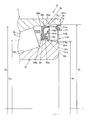
- the vehicle body-side seal mechanism 7 includes a first seal member 70 and a second seal member 71, and is disposed on the vehicle body side of the rolling element 5 among the double-row rolling elements 4, 5. ing.
- the first seal member 70 and the second seal member 71 are configured such that each independently exhibits a sealing function.
- the second seal member 71 is juxtaposed in the axially outer side (vehicle body side) of the first seal member 70.
- the vehicle body side seal mechanism 7 seals the inside of the rolling bearing A (the bearing inside) on the vehicle body side.
- the first seal member 70 includes a metal core 700, an elastic member 701, and a slinger 702.
- the first seal member 70 is formed between the outer peripheral surface of the second inner ring member 91 and the inner peripheral surface of the outer member 3 on the vehicle body side of the rolling element 5. It is arranged in between.
- the metal core 700 has a cylindrical portion 700a and an inner flange 700b, and is attached by press-fitting the cylindrical portion 700a into the outer member 3 from the vehicle body side.
- the core metal 700 is formed of a cylindrical member made of a material such as an austenitic stainless steel plate.
- the elastic member 701 includes a side lip 701a, a grease lip 701b, and a dust lip 701c.
- the elastic member 701 is joined (adhered) to the metal core 700 by, for example, vulcanization, and is pressed against the outer peripheral surface of the slinger 702 by a garter spring 703. .
- the elastic member 701 is formed of an annular member made of synthetic rubber such as NBR (nitrile-butadiene rubber).
- the side lip 701a is in sliding contact with the flange 702b of the slinger 702, the grease lip 701b is in sliding contact with the cylindrical portion 702a of the slinger 702 on the wheel side, and the dust 701c is in sliding contact with the cylindrical portion 702a of the slinger 702 on the vehicle body side.
- the elastic member 701 is provided with a folded portion 701d that projects between the opening end of the cylindrical portion 700a of the cored bar 700 and the inner peripheral surface of the outer member 3 so as to protrude radially outward. Thereby, the sealing performance between the opening end part of the cylindrical part 700a and the inner peripheral surface of the outer member 3 is enhanced.
- the slinger 702 has a cylindrical portion 702 a and a flange 702 b, and the cylindrical portion 702 a is attached to the outer peripheral surface of the second inner ring member 91.
- the cylindrical portion 702a of the slinger 702 is press-fitted into the outer peripheral surface of the second inner ring member 91 that is fixed to the hub wheel 8 in advance.
- the slinger 702 is formed of a cylindrical member made of a material such as an austenitic stainless steel plate.
- the cylindrical portion 702a faces the cylindrical portion 700a of the cored bar 700, and the flange 702b faces the inner flange 700b of the cored bar 700 via the elastic member 701.
- the second seal member 71 includes a metal core (base member) 710 and an elastic member 711, and the outer circumference of the inner ring side extending portion 91 b and the inner circumference of the outer ring side extending portion 3 d on the vehicle body side of the first seal member 70. It is arranged so as to be interposed between the surfaces.
- the core metal 710 is made of a material such as an austenitic stainless steel plate.
- the elastic member 711 is made of a synthetic rubber such as NBR (nitrile-butadiene rubber).
- the metal core 710 integrally includes a cylindrical cylindrical portion 710a press-fitted into the inner ring side extending portion 91b and an annular flange 710b protruding outward from the end of the cylindrical portion 710a on the vehicle body side.
- the elastic member 711 elastically contacts the base portion 711a joined (adhered) to the tip end portion (radially outward tip portion) of the flange 710b, for example, by the vulcanization method, and the inner peripheral surface of the outer ring side extending portion 3d.
- a lip portion (contact portion) 711 b is integrally formed, and the lip portion 711 b is disposed on the outer periphery of the cored bar 710.
- the vehicle body-side seal mechanism 7 has a first inner ring member 90 and a second inner ring member 91 constituting the inner ring 9 mounted in the recessed portion 8f of the hub wheel 8, and the vehicle body side end of the small-diameter body portion 8b in the hub wheel 8.
- the first seal member 70 is press-fitted between the outer peripheral surface of the second inner ring member 91 and the inner peripheral surface of the outer member 3 after the portions are crimped to form the crimped portion 8g.
- the second seal member 71 is assembled by being press-fitted between the inner ring side extending portion 91 b 91 and the outer ring side extending portion 3 d of the outer member 3.
- the second seal member 71 is on the bearing inner side (the rolling element 5 side) with respect to the axial end surface 91d on the vehicle body side of the second inner ring member 91 and the axial end surface 3e on the vehicle body side of the outer member 3. Placed in. That is, in the present embodiment, the first seal member 70 and the second seal member 71 are the vehicle body side axial end surface 91d of the second inner ring member 91 and the vehicle end side axial end surface of the outer member 3. It is arrange
- the first seal member 70 and the second seal member 71 are arranged in parallel in the direction of the central axis O, so that compared to a case where a single seal mechanism is used. Infiltration of muddy water or the like into the rolling bearing A is effectively prevented.
- the first seal member 70 and the second seal member 71 are disposed between the outer peripheral surface of the inner ring 9 (second inner ring member 91) and the inner peripheral surface of the outer member 3, for example, Compared with the case where only the first seal member 70 is disposed between the outer peripheral surface of the inner ring 9 and the inner peripheral surface of the outer member 3, and another seal member is separately disposed on the vehicle body side, the rolling bearing A In addition, the axial length of the wheel bearing device 1 can be shortened.
- the first seal member 70 and the second seal member 71 each independently perform a seal function.
- the elastic member 711 of the second seal member 71 is the slinger 702 of the first seal member 70. Since there is no lip portion in contact with the second sealing member 71, the package shape of the second seal member 71 can be improved. That is, if the lip portion 711b of the elastic member 711 of the second seal member 71 contacts the slinger 702 of the first seal member 70, the plurality of second seal members 71 are stacked in the axial direction and conveyed. During storage, the lip portion is strongly pressed against the cored bar 710 of the other adjacent second seal member 71. If this state continues for a long time, the lip portion is deformed and the sealing performance is lowered. However, in the present embodiment, since the lip portion 711b is configured to contact the inner peripheral surface of the outer member 3, there is no such fear.
- the press-fitting distance (the axial distance that pushes in the first seal member 70 while receiving the reaction force due to the press-fitting) when assembling the first seal member 70 can be shortened, the assembling workability is improved. Can be improved.
- the outer diameter Do 1 of the second inner ring member 91 in the inner ring side extending portion 91 b is set to the outer diameter Do of the second inner ring member 91 in the annular space a in which the first seal member 70 is accommodated. 2 (Do 1 ⁇ Do 2 ), and the inner diameter Di 1 of the outer member 3 in the outer ring side extending portion 3d is equal to the inner diameter Di 2 of the outer member 3 in the annular space a in which the first seal member 70 is accommodated.
- the sealing performance is good.
- the outer peripheral surface of the crimped portion is not necessarily a surface parallel to the central axis O, but a curved or inclined surface with respect to the axial direction (for example, accuracy such as roundness, or surface roughness) In such a case, the sealing performance of the sealing member is impaired.
- the lip portion 711b of the second seal member 71 contacts the inner peripheral surface of the outer member 3, it is possible to improve the sealing performance.
- FIG. 3 shows a main part of the rolling bearing. 3, members having the same or equivalent functions as those in FIGS. 1 and 2 are denoted by the same reference numerals, and detailed description thereof is omitted.
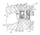
- the seal-side extending portion 716A of the elastic member 711A in the second seal member 71A protrudes outward from the core metal 712A.
- the lip portion 715A is provided on the inner side (bearing inner side) of the seal side extending portion 716A.
- the second seal member 71A has a cored bar 710A with an elastic member 711A and a flange 712A, and the cored bar 710A is press-fitted into the inner ring side extending portion 91b and is placed on the outer peripheral surface thereof. It is attached. Rubber or the like may be wound between the inner peripheral surface of the cored bar 710A and the outer peripheral surface of the inner ring side extending portion 91b in order to improve the sealing performance.
- the outer peripheral edge of the flange 712A is bent toward the rolling element 5, and an annular concave groove 713A that opens toward the first seal member 70 is formed. Accordingly, the base end portion of the lip portion 715A can be disposed at a deep position in the annular space b (on the rolling element 5 side), and the seal length of the elastic member 711A (the length of the lip portion 715A) is set to a large dimension. Thus, the sliding resistance with the outer member 3 is reduced.
- the elastic member 711A has a base portion 714A, a lip portion 715A, and a seal-side extending portion 716A, and is joined (adhered) to the outer groove wall and the groove bottom portion of the recessed groove 713A by, for example, a vulcanization method. It is formed of an annular member made of a synthetic rubber such as NBR (nitrile-butadiene rubber) which can be elastically deformed and is in sliding contact with the peripheral surface.
- NBR nonrile-butadiene rubber
- the base 714A functions as a mounted portion for the cored bar 710A, and is attached to the cored bar 710A with a part (inner peripheral edge) facing the inner peripheral surface. As a result, a gap formed between the outer peripheral surface of the inner ring side extending portion 91b and the inner peripheral surface of the base portion 714A is sealed, and the sealing performance of the second seal member 71A is enhanced.
- the base 714A is axial dimension L 1 is set according to the height of the outer groove wall of the groove 713A. This axial dimension L 1 is desirably at least one half of the axial length of the outer ring side extending portion 3d.
- the lip portion 715A is in contact with the inner peripheral surface of the outer ring side extending portion 3d, is integrally provided on the base portion 714A on the rolling element 5 side of the elastic member 711A, and is a first seal member in a direction parallel to the central axis O It is formed so as to be inclined to the opposite side to 70.
- the seal-side extending portion 716A is disposed at a position close to the inner peripheral surface of the outer ring-side extending portion 3d by extending the base portion 714A on the side opposite to the lip portion 715A side of the elastic member 711A (vehicle body side). Thereby, the radial dimension of the gap G formed between the seal-side extending portion 716A and the inner peripheral surface of the outer ring-side extending portion 3d is reduced, and muddy water or the like enters the second seal member 71A. The labyrinth effect which makes it difficult can be acquired.
- the lip portion 715A of the elastic member 711A can be made longer than that of the lip portion 711b according to the first embodiment, the lip portion 715A is more elastically the inner peripheral surface of the outer member 3 It is possible to make it contact, and it is possible to improve the sealing property and reduce the sliding resistance.
- the present invention is not limited to this,
- the cored bar 710 shown in the first embodiment may be used, and an elastic member 719A having a base 717A and a lip 718A may be attached to the cored bar 710.
- the base portion 717A is smaller than the axial dimension L 2 the elastic member 711A (shown in FIG.
- the lip portion 718A has a cylindrical convex portion 720A that protrudes toward the first seal member 70, and an end portion on the first seal member 70 side of the convex portion 720A that is opposite to the first seal member 70 side. It has a lip portion 721A as a contact portion formed by bending, and is provided integrally with the base portion 717A.
- FIG. 5 shows a main part of the rolling bearing.
- members having the same or equivalent functions as those in FIGS. 1 and 3 are denoted by the same reference numerals, and detailed description thereof is omitted.
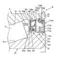
- the elastic member 711A of the second seal member 71A has a plurality of (two in this embodiment) lip portions 715A.
- a rust preventive member 722A is interposed between the lip portion 715A and the inner peripheral surface of the outer ring side extending portion 3d.
- the plurality of lip portions 715A are in sliding contact with the inner peripheral surface of the rust preventive member 722A and are arranged in parallel in the axial direction of the elastic member 711A.
- the lip portion on the vehicle body side is close to the inner peripheral surface of the rust preventive member 722A, and if the muddy water resistance (labyrinth effect) can be obtained, the inner periphery of the rust preventive member 722A. It is good also as a non-contact state which does not contact a surface.
- the rust preventive member 722A is made of a material such as an austenitic stainless steel plate, and has a cylindrical portion 723A and an inner flange 724A.
- the cylindrical portion 723A is press-fitted into the outer ring side extending portion 3d and attached to the inner peripheral surface thereof. ing.
- the outer member 3 is provided with a step surface 725A that abuts the inner flange 724A.
- the sliding portions (rust-proofing member 722A) of the plurality of lip portions 715A are less likely to rust, and good slidability can be obtained over a long period of time.
- the present invention is not limited to this, and as shown in FIG. It is good also as the rust prevention member 727A which has the flange 726A contact
- the rolling bearing is a tapered roller bearing in which the rolling elements 4 and 5 are tapered rollers.
- the present invention is not limited to this, and for example, the rolling element is a cylindrical roller.
- Other roller bearings may be used, and a rolling bearing composed of a ball bearing having rolling elements as balls may be used.
- the present invention is not limited to this.
- the outer ring may be rotatable.
- sliding contact portion 722A ... rust preventive member, 723A ... cylindrical portion, 24A ... inner flange, 725A ... stepped surface, 726A ... flange, 727A ... rust resistance member, a, b ... annular space, A, B, C ... rolling bearings, G ... gap, L 1, L 2 ... axial dimension , O ... center axis
Landscapes
- Engineering & Computer Science (AREA)
- General Engineering & Computer Science (AREA)
- Mechanical Engineering (AREA)
- Rolling Contact Bearings (AREA)
- Sealing Of Bearings (AREA)
Abstract
Description
(車輪用軸受装置の全体構成)
図1は車輪用軸受装置の全体を示す。図1に示すように、車輪用軸受装置1は、例えば駆動輪用の軸受装置であり、中心軸線Oの回りに回転可能な内方部材2と、内方部材2の外周囲に配置された外方部材3と、外方部材3と内方部材2との間に介在する複列の転動体4,5と、複列の転動体4,5の車輪側(車両アウタ側)と車体側(車両インナ側)とで転がり軸受(円すいころ軸受)Aの内部を封止する車輪側のシール機構6及び車体側のシール機構7とを備え、車体(図示せず)と車輪(図示せず)との間に配置されている。本実施の形態では、車体側のシール機構7が第1のシール部材70及び第2のシール部材71からなる。そして、車輪用軸受装置1は、車体側に転がり軸受Aを介してハブ輪8を回転可能に支持する。転がり軸受Aは、内輪9,外方部材3,転動体4,5,及びシール機構6,7を有するユニット部品として用いられる。
内方部材2は、ハブ輪8及び内輪9からなり、中心軸線O上に回転可能に配置されている。
外方部材3は、複列の転動体4,5をそれぞれ転動させる外側軌道面3a,3bを有し、車体側に懸架装置(図示せず)の構成部品としてのナックル(図示せず)を介して取り付けられている。また、外方部材3は、例えば中炭素鋼からなり、ABS(Anti-Lock Brake System)センサ12を取り付けるためのセンサ取付孔3cが設けられた略円筒状の成形体である。そして、外方部材3は、車輪用軸受装置1(転がり軸受A)の外輪として機能する。
複列の転動体4,5は、内輪9と外方部材3との間の軸受内部で転動可能に配置されている。車輪側列の転動体4は、円すいころからなり、第1の内輪部材90における第1の内側軌道面90aと、第1の内側軌道面90aに対向する外方部材3の外側軌道面3aとの間に介在して配置され、かつころ保持器13によって転動可能に保持されている。車体側列の転動体5は、車輪側列の転動体4と同様に円すいころからなり、第2の内輪部材91の第2の内側軌道面91aと、第2の内側軌道面91aに対向する外方部材3の外側軌道面3bとの間に介在して配置され、かつころ保持器14によって転動可能に保持されている。
車輪側のシール機構6は、芯金60及び弾性部材61を有し、複列の転動体4,5のうち転動体4の車輪側で第1の内輪部材90の外周面と外方部材3の内周面との間に介在して配置されている。そして、車輪側のシール機構6は、車輪側で転がり軸受Aの内部を封止する。
図2は転がり軸受の要部を示す。図2に示すように、車体側のシール機構7は、第1のシール部材70及び第2のシール部材71からなり、複列の転動体4,5のうち転動体5の車体側に配置されている。第1のシール部材70及び第2のシール部材71は、それぞれが独立してシール機能を発揮するように構成されている。第2のシール部材71は、第1のシール部材70の軸方向外側(車体側)に並列している。そして、車体側のシール機構7は、車体側で転がり軸受Aの内部(軸受内部)を封止する。これにより、本実施の形態では、車体側のシール機構7を単一のシール部材によって構成した場合と比べてシール性(耐泥水性)を高めることができる。
本実施の形態に示す車輪用軸受装置1の動作は、従来における車輪用軸受装置の動作と同様に行われる。すなわち、車両のエンジン側からトルクがドライブシャフト及び等速自在継手等を介してハブ輪8に伝達されると、ハブ輪8が内輪9と共に回転する。ハブ輪8には車輪が取り付けられているため、エンジン側からのトルクが車輪に伝達され、車輪がハブ輪9と共に回転する。この場合、車両の走行時に転がり軸受A内に対する泥水等の浸入が車輪側のシール機構6及び車体側のシール機構7で阻止される。特に、車体側のシール機構7においては、第1のシール部材70及び第2のシール部材71が中心軸線O方向に並列して配置されているため、単一のシール機構とする場合と比べて転がり軸受A内に対する泥水等の浸入阻止が効果的に行われる。
以上説明した第1の実施の形態によれば、次に示す効果が得られる。
次に、本発明の第2実施の形態に係る転がり軸受につき、図3を用いて説明する。図3は転がり軸受の要部を示す。図3において、図1及び図2と同一又は同等の機能をもつ部材については同一の符号を付し、詳細な説明は省略する。
以上説明した第2の実施の形態によれば、第1の実施の形態に示す上記(1)~(5)に記載の効果に加えて、次に示す効果が得られる。
次に、本発明の第3実施の形態に係る転がり軸受につき、図5を用いて説明する。図5は転がり軸受の要部を示す。図5において、図1及び図3と同一又は同等の機能をもつ部材については同一の符号を付し、詳細な説明は省略する。
以上説明した第3の実施の形態によれば、第1の実施の形態に示す上記(1)~(5)に記載の効果に加えて次に示す効果が得られる。
Claims (4)
- 内側軌道面を有する内輪と、
前記内輪の外周囲に配置され、前記内側軌道面に対向する外側軌道面を有する外輪と、
前記内輪と前記外輪の間の軸受内部で前記内側軌道面及び前記外側軌道面を転動する複数の転動体と、
前記内輪の外周面と前記外輪の内周面との間に介在して配置され、前記軸受内部を封止する第1のシール部材と、
前記第1のシール部材の軸方向外側に並列する第2のシール部材とを備え、
前記第1のシール部材及び前記第2のシール部材は、前記内輪の軸方向端面及び前記外輪の軸方向端面よりも前記軸受内部側に配置されている
転がり軸受。 - 前記第2のシール部材は、前記内輪の外周面に取り付けられた基部材、及び基部材に接合された弾性部材を有し、前記弾性部材のうち前記外輪の内周面に弾性的に接触する接触部が前記基部材の外周囲に配置されている、
請求項1に記載の転がり軸受。 - 前記第2シール部材の内周側における前記内輪の外径は前記第1シール部材の内周側における前記内輪の外径よりも小さい、
請求項1又は2に記載の転がり軸受。 - 前記第2シール部材の外周側における前記外輪の内径は前記第1シール部材の外周側における前記外輪の外径よりも大きい、
請求項1乃至3の何れか1項に記載の転がり軸受。
Priority Applications (3)
| Application Number | Priority Date | Filing Date | Title |
|---|---|---|---|
| CN201380064540.XA CN104838159A (zh) | 2012-12-12 | 2013-11-19 | 滚动轴承 |
| US14/651,919 US20150316103A1 (en) | 2012-12-12 | 2013-11-19 | Rolling bearing |
| DE112013005935.5T DE112013005935T5 (de) | 2012-12-12 | 2013-11-19 | Wälzlager |
Applications Claiming Priority (2)
| Application Number | Priority Date | Filing Date | Title |
|---|---|---|---|
| JP2012271208A JP2014114931A (ja) | 2012-12-12 | 2012-12-12 | 転がり軸受 |
| JP2012-271208 | 2012-12-12 |
Publications (1)
| Publication Number | Publication Date |
|---|---|
| WO2014091883A1 true WO2014091883A1 (ja) | 2014-06-19 |
Family
ID=50934178
Family Applications (1)
| Application Number | Title | Priority Date | Filing Date |
|---|---|---|---|
| PCT/JP2013/081089 Ceased WO2014091883A1 (ja) | 2012-12-12 | 2013-11-19 | 転がり軸受 |
Country Status (5)
| Country | Link |
|---|---|
| US (1) | US20150316103A1 (ja) |
| JP (1) | JP2014114931A (ja) |
| CN (1) | CN104838159A (ja) |
| DE (1) | DE112013005935T5 (ja) |
| WO (1) | WO2014091883A1 (ja) |
Families Citing this family (6)
| Publication number | Priority date | Publication date | Assignee | Title |
|---|---|---|---|---|
| US20170146064A1 (en) * | 2015-11-23 | 2017-05-25 | Jixian Lyu | Bearing Assembly with Oil Seal Arrangement |
| WO2017091071A1 (en) | 2015-11-27 | 2017-06-01 | Itrec B.V. | Sealed rolling elements bearing |
| JP6692214B2 (ja) * | 2016-05-24 | 2020-05-13 | Ntn株式会社 | 軸受密封装置 |
| AT520701B1 (de) * | 2017-11-20 | 2020-03-15 | Skf Ab | Schrägkontaktwälzlager |
| IT202000009991A1 (it) * | 2020-05-06 | 2021-11-06 | Skf Ab | Gruppo mozzo-cuscinetto per dischi per la lavorazione del terreno |
| US20230250848A1 (en) * | 2022-02-07 | 2023-08-10 | Bpb Mediterranea S.A. | Integral hammer for the assembly of sowing discs of a seeding machine |
Citations (2)
| Publication number | Priority date | Publication date | Assignee | Title |
|---|---|---|---|---|
| JP2006029514A (ja) * | 2004-07-20 | 2006-02-02 | Ntn Corp | センサ付軸受 |
| JP2010019340A (ja) * | 2008-07-10 | 2010-01-28 | Jtekt Corp | 車軸用軸受装置 |
Family Cites Families (6)
| Publication number | Priority date | Publication date | Assignee | Title |
|---|---|---|---|---|
| JPS62278315A (ja) * | 1986-05-24 | 1987-12-03 | Koyo Seiko Co Ltd | 軸受装置 |
| JP2006214557A (ja) * | 2005-02-07 | 2006-08-17 | Ntn Corp | 密封型転がり軸受 |
| JP2006349043A (ja) * | 2005-06-15 | 2006-12-28 | Ntn Corp | 密封型転がり軸受 |
| US8237431B2 (en) * | 2007-07-05 | 2012-08-07 | Terry Fruehling | Wheel speed sensor |
| JP2012241824A (ja) * | 2011-05-20 | 2012-12-10 | Nsk Ltd | パックシール付軸受ユニット |
| CN202520789U (zh) * | 2012-04-27 | 2012-11-07 | 上海中隆轴承有限公司 | 带轴向唇的双密封圈的组合密封结构 |
-
2012
- 2012-12-12 JP JP2012271208A patent/JP2014114931A/ja active Pending
-
2013
- 2013-11-19 US US14/651,919 patent/US20150316103A1/en not_active Abandoned
- 2013-11-19 CN CN201380064540.XA patent/CN104838159A/zh active Pending
- 2013-11-19 DE DE112013005935.5T patent/DE112013005935T5/de not_active Withdrawn
- 2013-11-19 WO PCT/JP2013/081089 patent/WO2014091883A1/ja not_active Ceased
Patent Citations (2)
| Publication number | Priority date | Publication date | Assignee | Title |
|---|---|---|---|---|
| JP2006029514A (ja) * | 2004-07-20 | 2006-02-02 | Ntn Corp | センサ付軸受 |
| JP2010019340A (ja) * | 2008-07-10 | 2010-01-28 | Jtekt Corp | 車軸用軸受装置 |
Also Published As
| Publication number | Publication date |
|---|---|
| CN104838159A (zh) | 2015-08-12 |
| US20150316103A1 (en) | 2015-11-05 |
| DE112013005935T5 (de) | 2015-09-10 |
| JP2014114931A (ja) | 2014-06-26 |
Similar Documents
| Publication | Publication Date | Title |
|---|---|---|
| US8303190B2 (en) | Wheel bearing apparatus for a vehicle | |
| JP5184820B2 (ja) | 車輪用軸受装置 | |
| JP2009197884A (ja) | 車輪用軸受装置 | |
| JP2014114931A (ja) | 転がり軸受 | |
| JP2009197883A (ja) | 車輪用軸受装置 | |
| JP5468751B2 (ja) | 車輪用軸受装置 | |
| JP4873606B2 (ja) | 車輪用軸受装置 | |
| JP5328136B2 (ja) | 車輪用軸受 | |
| JP2010043670A (ja) | 車輪用軸受装置 | |
| WO2007138738A1 (ja) | 車輪用軸受装置 | |
| JP2011089619A (ja) | 車輪用軸受装置 | |
| JP2007192392A (ja) | 車輪用軸受装置 | |
| JP2008247072A (ja) | 車輪支持装置 | |
| JP5408764B2 (ja) | パックシール | |
| JP5414964B2 (ja) | 車輪用軸受装置 | |
| JP5105397B2 (ja) | 駆動車輪用軸受装置 | |
| JP2005330987A (ja) | 密封ころがり軸受および密封シール | |
| JP6968044B2 (ja) | 車輪用軸受装置 | |
| JP2008180300A (ja) | 車輪用軸受装置 | |
| JP6709635B2 (ja) | 車輪用軸受装置 | |
| JP7763621B2 (ja) | 車輪軸受用シール装置 | |
| JP2008075834A (ja) | 転がり軸受装置 | |
| JP6618810B2 (ja) | 等速自在継手 | |
| JP6483460B2 (ja) | 密封装置およびこれを備えた車輪用軸受装置 | |
| JP2008157327A (ja) | 車輪用軸受装置 |
Legal Events
| Date | Code | Title | Description |
|---|---|---|---|
| 121 | Ep: the epo has been informed by wipo that ep was designated in this application |
Ref document number: 13862463 Country of ref document: EP Kind code of ref document: A1 |
|
| WWE | Wipo information: entry into national phase |
Ref document number: 14651919 Country of ref document: US Ref document number: 1120130059355 Country of ref document: DE Ref document number: 112013005935 Country of ref document: DE |
|
| 122 | Ep: pct application non-entry in european phase |
Ref document number: 13862463 Country of ref document: EP Kind code of ref document: A1 |