WO2014091846A1 - 穿刺具及び超音波内視鏡 - Google Patents
穿刺具及び超音波内視鏡 Download PDFInfo
- Publication number
- WO2014091846A1 WO2014091846A1 PCT/JP2013/080222 JP2013080222W WO2014091846A1 WO 2014091846 A1 WO2014091846 A1 WO 2014091846A1 JP 2013080222 W JP2013080222 W JP 2013080222W WO 2014091846 A1 WO2014091846 A1 WO 2014091846A1
- Authority
- WO
- WIPO (PCT)
- Prior art keywords
- blade
- needle tube
- tip
- puncture
- opening
- Prior art date
Links
- 238000012545 processing Methods 0.000 claims description 16
- 230000009191 jumping Effects 0.000 claims description 3
- 229910052751 metal Inorganic materials 0.000 claims description 3
- 239000002184 metal Substances 0.000 claims description 3
- 230000001590 oxidative effect Effects 0.000 claims description 2
- 206010028980 Neoplasm Diseases 0.000 description 97
- LFQSCWFLJHTTHZ-UHFFFAOYSA-N Ethanol Chemical compound CCO LFQSCWFLJHTTHZ-UHFFFAOYSA-N 0.000 description 54
- 238000003780 insertion Methods 0.000 description 52
- 230000037431 insertion Effects 0.000 description 52
- 238000012986 modification Methods 0.000 description 47
- 230000004048 modification Effects 0.000 description 47
- 230000003902 lesion Effects 0.000 description 31
- 239000002504 physiological saline solution Substances 0.000 description 24
- 238000010586 diagram Methods 0.000 description 13
- 238000000034 method Methods 0.000 description 13
- 210000000496 pancreas Anatomy 0.000 description 10
- 210000002784 stomach Anatomy 0.000 description 8
- 230000000694 effects Effects 0.000 description 7
- 230000002093 peripheral effect Effects 0.000 description 7
- 238000007790 scraping Methods 0.000 description 5
- 239000007924 injection Substances 0.000 description 4
- 238000002347 injection Methods 0.000 description 4
- 229910000679 solder Inorganic materials 0.000 description 4
- 238000001356 surgical procedure Methods 0.000 description 4
- 230000021164 cell adhesion Effects 0.000 description 3
- 238000005286 illumination Methods 0.000 description 3
- 238000011273 incision biopsy Methods 0.000 description 3
- 239000012212 insulator Substances 0.000 description 3
- 238000011084 recovery Methods 0.000 description 3
- 229910000684 Cobalt-chrome Inorganic materials 0.000 description 2
- HZEWFHLRYVTOIW-UHFFFAOYSA-N [Ti].[Ni] Chemical compound [Ti].[Ni] HZEWFHLRYVTOIW-UHFFFAOYSA-N 0.000 description 2
- 239000000853 adhesive Substances 0.000 description 2
- 230000001070 adhesive effect Effects 0.000 description 2
- 229910045601 alloy Inorganic materials 0.000 description 2
- 239000000956 alloy Substances 0.000 description 2
- 238000013459 approach Methods 0.000 description 2
- 238000005452 bending Methods 0.000 description 2
- 239000011230 binding agent Substances 0.000 description 2
- 210000004204 blood vessel Anatomy 0.000 description 2
- 239000010952 cobalt-chrome Substances 0.000 description 2
- 210000003238 esophagus Anatomy 0.000 description 2
- 230000002439 hemostatic effect Effects 0.000 description 2
- 239000007788 liquid Substances 0.000 description 2
- 210000004185 liver Anatomy 0.000 description 2
- 229910001000 nickel titanium Inorganic materials 0.000 description 2
- 210000000056 organ Anatomy 0.000 description 2
- 238000000554 physical therapy Methods 0.000 description 2
- 230000002265 prevention Effects 0.000 description 2
- 239000010935 stainless steel Substances 0.000 description 2
- 229910001220 stainless steel Inorganic materials 0.000 description 2
- 206010061902 Pancreatic neoplasm Diseases 0.000 description 1
- 239000004642 Polyimide Substances 0.000 description 1
- 102000004142 Trypsin Human genes 0.000 description 1
- 108090000631 Trypsin Proteins 0.000 description 1
- 238000001574 biopsy Methods 0.000 description 1
- 201000011510 cancer Diseases 0.000 description 1
- 238000002512 chemotherapy Methods 0.000 description 1
- 239000011248 coating agent Substances 0.000 description 1
- 238000000576 coating method Methods 0.000 description 1
- 230000006835 compression Effects 0.000 description 1
- 238000007906 compression Methods 0.000 description 1
- 239000012141 concentrate Substances 0.000 description 1
- 239000003814 drug Substances 0.000 description 1
- 229940079593 drug Drugs 0.000 description 1
- 238000010292 electrical insulation Methods 0.000 description 1
- 239000000835 fiber Substances 0.000 description 1
- 239000012634 fragment Substances 0.000 description 1
- 210000000232 gallbladder Anatomy 0.000 description 1
- 238000003384 imaging method Methods 0.000 description 1
- 238000007386 incisional biopsy Methods 0.000 description 1
- 238000003754 machining Methods 0.000 description 1
- 208000015486 malignant pancreatic neoplasm Diseases 0.000 description 1
- 239000000463 material Substances 0.000 description 1
- 210000005036 nerve Anatomy 0.000 description 1
- 230000003287 optical effect Effects 0.000 description 1
- 201000002528 pancreatic cancer Diseases 0.000 description 1
- 208000008443 pancreatic carcinoma Diseases 0.000 description 1
- 229940012957 plasmin Drugs 0.000 description 1
- 229920001721 polyimide Polymers 0.000 description 1
- 238000001959 radiotherapy Methods 0.000 description 1
- 208000011580 syndromic disease Diseases 0.000 description 1
- 239000012588 trypsin Substances 0.000 description 1
- 238000002604 ultrasonography Methods 0.000 description 1
- 238000003466 welding Methods 0.000 description 1
Images


Classifications
-
- A—HUMAN NECESSITIES
- A61—MEDICAL OR VETERINARY SCIENCE; HYGIENE
- A61B—DIAGNOSIS; SURGERY; IDENTIFICATION
- A61B17/00—Surgical instruments, devices or methods, e.g. tourniquets
- A61B17/32—Surgical cutting instruments
- A61B17/320016—Endoscopic cutting instruments, e.g. arthroscopes, resectoscopes
-
- A—HUMAN NECESSITIES
- A61—MEDICAL OR VETERINARY SCIENCE; HYGIENE
- A61B—DIAGNOSIS; SURGERY; IDENTIFICATION
- A61B18/00—Surgical instruments, devices or methods for transferring non-mechanical forms of energy to or from the body
- A61B18/04—Surgical instruments, devices or methods for transferring non-mechanical forms of energy to or from the body by heating
- A61B18/12—Surgical instruments, devices or methods for transferring non-mechanical forms of energy to or from the body by heating by passing a current through the tissue to be heated, e.g. high-frequency current
- A61B18/14—Probes or electrodes therefor
- A61B18/1492—Probes or electrodes therefor having a flexible, catheter-like structure, e.g. for heart ablation
-
- A—HUMAN NECESSITIES
- A61—MEDICAL OR VETERINARY SCIENCE; HYGIENE
- A61B—DIAGNOSIS; SURGERY; IDENTIFICATION
- A61B8/00—Diagnosis using ultrasonic, sonic or infrasonic waves
- A61B8/12—Diagnosis using ultrasonic, sonic or infrasonic waves in body cavities or body tracts, e.g. by using catheters
-
- A—HUMAN NECESSITIES
- A61—MEDICAL OR VETERINARY SCIENCE; HYGIENE
- A61B—DIAGNOSIS; SURGERY; IDENTIFICATION
- A61B10/00—Other methods or instruments for diagnosis, e.g. instruments for taking a cell sample, for biopsy, for vaccination diagnosis; Sex determination; Ovulation-period determination; Throat striking implements
- A61B10/02—Instruments for taking cell samples or for biopsy
- A61B10/0233—Pointed or sharp biopsy instruments
- A61B10/0266—Pointed or sharp biopsy instruments means for severing sample
- A61B10/0275—Pointed or sharp biopsy instruments means for severing sample with sample notch, e.g. on the side of inner stylet
-
- A—HUMAN NECESSITIES
- A61—MEDICAL OR VETERINARY SCIENCE; HYGIENE
- A61B—DIAGNOSIS; SURGERY; IDENTIFICATION
- A61B17/00—Surgical instruments, devices or methods, e.g. tourniquets
- A61B17/32—Surgical cutting instruments
- A61B17/3205—Excision instruments
- A61B17/3207—Atherectomy devices working by cutting or abrading; Similar devices specially adapted for non-vascular obstructions
- A61B17/320708—Curettes, e.g. hollow scraping instruments
-
- A—HUMAN NECESSITIES
- A61—MEDICAL OR VETERINARY SCIENCE; HYGIENE
- A61B—DIAGNOSIS; SURGERY; IDENTIFICATION
- A61B18/00—Surgical instruments, devices or methods for transferring non-mechanical forms of energy to or from the body
- A61B18/04—Surgical instruments, devices or methods for transferring non-mechanical forms of energy to or from the body by heating
- A61B18/12—Surgical instruments, devices or methods for transferring non-mechanical forms of energy to or from the body by heating by passing a current through the tissue to be heated, e.g. high-frequency current
- A61B18/1206—Generators therefor
-
- A—HUMAN NECESSITIES
- A61—MEDICAL OR VETERINARY SCIENCE; HYGIENE
- A61B—DIAGNOSIS; SURGERY; IDENTIFICATION
- A61B18/00—Surgical instruments, devices or methods for transferring non-mechanical forms of energy to or from the body
- A61B18/04—Surgical instruments, devices or methods for transferring non-mechanical forms of energy to or from the body by heating
- A61B18/12—Surgical instruments, devices or methods for transferring non-mechanical forms of energy to or from the body by heating by passing a current through the tissue to be heated, e.g. high-frequency current
- A61B18/14—Probes or electrodes therefor
- A61B18/1477—Needle-like probes
-
- A—HUMAN NECESSITIES
- A61—MEDICAL OR VETERINARY SCIENCE; HYGIENE
- A61B—DIAGNOSIS; SURGERY; IDENTIFICATION
- A61B8/00—Diagnosis using ultrasonic, sonic or infrasonic waves
- A61B8/44—Constructional features of the ultrasonic, sonic or infrasonic diagnostic device
- A61B8/4444—Constructional features of the ultrasonic, sonic or infrasonic diagnostic device related to the probe
- A61B8/445—Details of catheter construction
-
- A—HUMAN NECESSITIES
- A61—MEDICAL OR VETERINARY SCIENCE; HYGIENE
- A61B—DIAGNOSIS; SURGERY; IDENTIFICATION
- A61B10/00—Other methods or instruments for diagnosis, e.g. instruments for taking a cell sample, for biopsy, for vaccination diagnosis; Sex determination; Ovulation-period determination; Throat striking implements
- A61B10/02—Instruments for taking cell samples or for biopsy
- A61B10/04—Endoscopic instruments
- A61B2010/045—Needles
-
- A—HUMAN NECESSITIES
- A61—MEDICAL OR VETERINARY SCIENCE; HYGIENE
- A61B—DIAGNOSIS; SURGERY; IDENTIFICATION
- A61B17/00—Surgical instruments, devices or methods, e.g. tourniquets
- A61B17/32—Surgical cutting instruments
- A61B17/3205—Excision instruments
- A61B17/3207—Atherectomy devices working by cutting or abrading; Similar devices specially adapted for non-vascular obstructions
- A61B17/320783—Atherectomy devices working by cutting or abrading; Similar devices specially adapted for non-vascular obstructions through side-hole, e.g. sliding or rotating cutter inside catheter
- A61B2017/320791—Atherectomy devices working by cutting or abrading; Similar devices specially adapted for non-vascular obstructions through side-hole, e.g. sliding or rotating cutter inside catheter with cutter extending outside the cutting window
-
- A—HUMAN NECESSITIES
- A61—MEDICAL OR VETERINARY SCIENCE; HYGIENE
- A61B—DIAGNOSIS; SURGERY; IDENTIFICATION
- A61B18/00—Surgical instruments, devices or methods for transferring non-mechanical forms of energy to or from the body
- A61B2018/00982—Surgical instruments, devices or methods for transferring non-mechanical forms of energy to or from the body combined with or comprising means for visual or photographic inspections inside the body, e.g. endoscopes
-
- A—HUMAN NECESSITIES
- A61—MEDICAL OR VETERINARY SCIENCE; HYGIENE
- A61B—DIAGNOSIS; SURGERY; IDENTIFICATION
- A61B18/00—Surgical instruments, devices or methods for transferring non-mechanical forms of energy to or from the body
- A61B18/04—Surgical instruments, devices or methods for transferring non-mechanical forms of energy to or from the body by heating
- A61B18/12—Surgical instruments, devices or methods for transferring non-mechanical forms of energy to or from the body by heating by passing a current through the tissue to be heated, e.g. high-frequency current
- A61B18/1206—Generators therefor
- A61B2018/124—Generators therefor switching the output to different electrodes, e.g. sequentially
-
- A—HUMAN NECESSITIES
- A61—MEDICAL OR VETERINARY SCIENCE; HYGIENE
- A61B—DIAGNOSIS; SURGERY; IDENTIFICATION
- A61B18/00—Surgical instruments, devices or methods for transferring non-mechanical forms of energy to or from the body
- A61B18/04—Surgical instruments, devices or methods for transferring non-mechanical forms of energy to or from the body by heating
- A61B18/12—Surgical instruments, devices or methods for transferring non-mechanical forms of energy to or from the body by heating by passing a current through the tissue to be heated, e.g. high-frequency current
- A61B18/1206—Generators therefor
- A61B2018/1273—Generators therefor including multiple generators in one device
-
- A—HUMAN NECESSITIES
- A61—MEDICAL OR VETERINARY SCIENCE; HYGIENE
- A61B—DIAGNOSIS; SURGERY; IDENTIFICATION
- A61B18/00—Surgical instruments, devices or methods for transferring non-mechanical forms of energy to or from the body
- A61B18/04—Surgical instruments, devices or methods for transferring non-mechanical forms of energy to or from the body by heating
- A61B18/12—Surgical instruments, devices or methods for transferring non-mechanical forms of energy to or from the body by heating by passing a current through the tissue to be heated, e.g. high-frequency current
- A61B18/14—Probes or electrodes therefor
- A61B2018/1405—Electrodes having a specific shape
- A61B2018/1412—Blade
-
- A—HUMAN NECESSITIES
- A61—MEDICAL OR VETERINARY SCIENCE; HYGIENE
- A61B—DIAGNOSIS; SURGERY; IDENTIFICATION
- A61B18/00—Surgical instruments, devices or methods for transferring non-mechanical forms of energy to or from the body
- A61B18/04—Surgical instruments, devices or methods for transferring non-mechanical forms of energy to or from the body by heating
- A61B18/12—Surgical instruments, devices or methods for transferring non-mechanical forms of energy to or from the body by heating by passing a current through the tissue to be heated, e.g. high-frequency current
- A61B18/14—Probes or electrodes therefor
- A61B2018/1405—Electrodes having a specific shape
- A61B2018/1425—Needle
-
- A—HUMAN NECESSITIES
- A61—MEDICAL OR VETERINARY SCIENCE; HYGIENE
- A61B—DIAGNOSIS; SURGERY; IDENTIFICATION
- A61B18/00—Surgical instruments, devices or methods for transferring non-mechanical forms of energy to or from the body
- A61B18/04—Surgical instruments, devices or methods for transferring non-mechanical forms of energy to or from the body by heating
- A61B18/12—Surgical instruments, devices or methods for transferring non-mechanical forms of energy to or from the body by heating by passing a current through the tissue to be heated, e.g. high-frequency current
- A61B18/14—Probes or electrodes therefor
- A61B2018/1475—Electrodes retractable in or deployable from a housing
-
- A—HUMAN NECESSITIES
- A61—MEDICAL OR VETERINARY SCIENCE; HYGIENE
- A61B—DIAGNOSIS; SURGERY; IDENTIFICATION
- A61B90/00—Instruments, implements or accessories specially adapted for surgery or diagnosis and not covered by any of the groups A61B1/00 - A61B50/00, e.g. for luxation treatment or for protecting wound edges
- A61B90/39—Markers, e.g. radio-opaque or breast lesions markers
- A61B2090/3925—Markers, e.g. radio-opaque or breast lesions markers ultrasonic
-
- A—HUMAN NECESSITIES
- A61—MEDICAL OR VETERINARY SCIENCE; HYGIENE
- A61B—DIAGNOSIS; SURGERY; IDENTIFICATION
- A61B2218/00—Details of surgical instruments, devices or methods for transferring non-mechanical forms of energy to or from the body
- A61B2218/001—Details of surgical instruments, devices or methods for transferring non-mechanical forms of energy to or from the body having means for irrigation and/or aspiration of substances to and/or from the surgical site
- A61B2218/007—Aspiration
Definitions
- the present invention relates to a puncture device and an ultrasonic endoscope, and more particularly to a puncture device and an ultrasonic endoscope that can reduce the size of a lesion while preventing attachment of living lesion cells during removal.
- Japanese Patent Application Laid-Open No. 2000-116657 proposes an incision biopsy device for excising a lesion.
- the lesioned part is excised by bending a thin ribbon-shaped cutting tool provided at the tip of the biopsy device and rotating the bent cutting tool.
- the excised lesioned part is accommodated in a bag-shaped tissue accommodating apparatus joined to a cutting tool, and the entire incision biopsy apparatus is pulled out of the body, and then excised.
- the present invention can reduce the lesion by puncturing the lesion and scraping the inside of the lesion, and the living lesion cells are attached to the incised site when removed from the lesion It is an object of the present invention to provide a puncture device that can prevent the puncture and an ultrasonic endoscope including the puncture device.
- a tubular portion having a channel having an opening on the side at the distal end side, and a proximal end side of the tubular portion so as to communicate with the channel are connected to a suction device.
- a puncture device comprising: a blade capable of projecting a cutting portion from the opening when inserted into the channel; and a first power supply connection portion for electrically connecting the puncture portion and a power source. be able to.
- an ultrasonic wave including the puncture device of the present invention and an ultrasonic observation unit that transmits ultrasonic waves toward the puncture device and receives ultrasonic waves reflected from the puncture device.
- An endoscope can be provided.
- FIG. 3 is a cross-sectional view of the distal end portion of the puncture device insertion portion 9A along the line III-III in FIG.
- FIG. 4 is a cross-sectional view of the distal end portion of the puncture device insertion portion 9A taken along line IV-IV in FIG.
- FIG. 7 is a cross-sectional view of the puncture tool operation unit 9B along the line VII-VII in FIG. It is sectional drawing of the puncture tool operation part 9B in the state which the sheath 41 protruded most from the treatment tool opening of the front-end
- FIG. 25 is a sectional view taken along line XXV-XXV in FIG. 24. It is a perspective view of the blade front-end
- the spherical extension 22a12 of the blade tip 22a abuts on the tip 21d1 of the internal space 21d, and the blade 22 is further pushed to the tip.
- FIG. 6 is a cross-sectional view showing a state in which a blade tip 22a is curved.
- FIG. 29 is a cross-sectional view of the distal end portion of the puncture instrument insertion portion 9A along the line XXIX-XXIX in FIG.
- It is a block diagram which shows the structure of the surgery system 1A using the ultrasonic endoscope which concerns on the modification 5 of the 1st Embodiment of this invention.
- It is an external view of the puncture tool operation part 9BX which concerns on the modification 5 of the 1st Embodiment of this invention.
- FIG. 32 is a cross-sectional view of the puncture tool operation unit 9B along the line XXXII-XXXII in FIG. 31.
- FIG. 37 is a cross-sectional view of a needle tube distal end portion 71 taken along line XXXVII-XXXVII in FIG. 36. It is a perspective view of the blade front-end
- FIG. 1 is a configuration diagram showing a configuration of a surgical system using the ultrasonic endoscope according to the first embodiment.
- an operation system 1 includes an ultrasonic endoscope 2, a video processor 3, a light source device 4, a monitor 5, an ultrasonic observation device 6, a monitor 7, and a high frequency power supply device 8. And a puncture device 9 as a treatment device.
- the ultrasonic endoscope 2 includes a long and thin endoscope insertion portion 11, an endoscope operation portion 12, and a universal cord 13.
- a distal end hard portion 14 is provided at the distal end portion of the endoscope insertion portion 11.
- a treatment instrument insertion port 12a is provided on the distal end side of the endoscope operation unit 12, and the ultrasonic endoscope 2 is configured so that the puncture device 9 can be attached to the treatment instrument insertion port 12a. Yes.
- the ultrasonic endoscope and the puncture device 9 may be integrated.
- the distal end hard portion 14 includes an illumination window that emits illumination light from the light source device 4, an observation window, an image sensor provided on the rear side of the observation window, and an ultrasonic vibration portion 14a ( FIG. 15) is provided. That is, the ultrasonic endoscope 2 includes an ultrasonic vibration unit 14 a as an ultrasonic observation unit that transmits ultrasonic waves toward the puncture tool 9 and receives ultrasonic waves reflected from the puncture tool 9.
- the operator SG grasps the endoscope operation unit 12 of the ultrasonic endoscope 2 with one hand, grasps the endoscope insertion unit 11 with the other hand, and from the mouth of the patient PA on the bed 15.
- the endoscope insertion part 11 is inserted.
- the inside of the body irradiated with the illumination light from the light source device 4 is imaged by the imaging element at the distal end portion of the endoscope insertion portion 11.
- the image signal from the image sensor is subjected to image processing by the video processor 3, and an endoscopic image is displayed on the monitor 5.
- the ultrasonic video signal obtained by the ultrasonic vibration unit at the distal end of the endoscope insertion unit 11 is subjected to image processing by the ultrasonic observation device 6, and an ultrasonic image is displayed on the monitor 7.
- the surgeon SG can perform the insertion operation of the endoscope insertion unit 11 while viewing the endoscope optical image displayed on the monitor 5 and can also view the ultrasonic image displayed on the monitor 7.
- the lesioned part can be treated using the puncture device 9.
- the puncture device 9 can perform a treatment using a high-frequency current, and when the needle tube 21 (FIG. 2) of the puncture device 9 is pulled out from the living tissue, the needle tube 21 is used to prevent lesion cell adhesion.
- a high-frequency current can be passed through.
- the puncture tool 9 includes two cables 9a and 9b and two connectors 9a1 and 9b1 provided at the ends of the two cables 9a and 9b.
- a counter electrode 15 a that is in contact with the patient PA is placed on the bed 15 in order to pass a high-frequency current through the puncture device 9.
- the high frequency power supply device 8 has two connectors 8a and 8b.
- a connector 9a1 is connected to the connector 8a, and a connector 9b1 is connected to the connector 8b.
- a high frequency current is supplied to the blade 22 (FIG. 5) of the puncture tool 9 via the cable 9a, and a high frequency current is supplied to the needle tube 21 (FIG. 2) of the puncture tool 9 via the cable 9b.
- the high frequency current can be supplied to each of the blade 22 and the needle tube 21 by an operation of a switch (not shown) provided in the high frequency power supply device 8 by an operator.
- the puncture device 9 can be attached with a syringe 16.
- the syringe 16 is a suction device that can inject a liquid into the needle tube 21 and suck a liquid or the like from the needle tube 21.
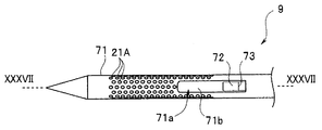
- the puncture device 9 is provided on the elongate puncture device insertion portion 9A through which the needle tube 21 and the blade 22 are inserted, and on the proximal end side of the puncture device insertion portion 9A, and the puncture device operation portion 9B for performing the protrusion operation of the needle tube 21 and the like. And have.
- the puncture tool insertion section 9A is inserted from the treatment instrument insertion port 12a of the endoscope operation section 12, passes through the treatment instrument insertion channel in the endoscope insertion section 11, and the distal end portion of the puncture instrument insertion section 9A is hard at the distal end.
- the puncture device 9 is configured to be able to protrude from the treatment device opening of the portion 14.
- the puncture device insertion portion 9A includes a sheath 41 and a needle tube 21 and a blade 22 inserted into the sheath 41.
- FIG. 2 is a plan view of the distal end portion of the puncture device insertion portion 9A.
- FIG. 3 is a cross-sectional view of the distal end portion of the puncture instrument insertion portion 9A along the line III-III in FIG.
- FIG. 4 is a cross-sectional view of the distal end portion of the puncture device insertion portion 9A taken along line IV-IV in FIG.
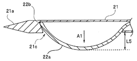
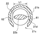
- FIG. 5 is a perspective view of the tip of the blade 22.
- the puncture instrument insertion portion 9A includes a sheath 41 (FIG. 7) not shown in FIG. 2, a needle tube 21 inserted into the sheath 41, and a blade 22 inserted into the needle tube 21.
- the needle tube 21 is a tubular member such as stainless steel, nickel titanium, cobalt chrome alloy, or the like, with a hole on the distal end surface closed by welding or the like.
- the needle tube 21 constitutes a tubular portion having a channel having an opening on the side at the tip side.
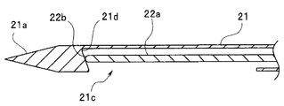
- the hollow and elongate needle tube 21 has a needle tube tip portion 21b having a conical portion 21a pointed at the tip.
- the needle tube tip 21b has an elongated opening 21c formed along the axial direction.
- the opening 21c is provided in the vicinity of the conical portion 21a. That is, the opening 21 c is provided on the proximal end side of the distal end portion of the needle tube distal end portion 21 b and communicates with a channel in the needle tube 21.
- the conical portion 21a is disposed on the distal end surface of the needle tube 21 that is a tubular portion, and constitutes a puncture portion for puncturing the subject.
- the diameter of the needle tube 21 is, for example, 22G to 19G (gauge).
- the length of the opening 21c in the axial direction is, for example, 5 to 15 mm. That is, the tip of the needle tube 21 has a so-called pencil shape.
- a blade 22 that is an elongated shaft member having a circular cross section is inserted into the internal space 21d of the hollow needle tube tip 21b.
- the diameter of the shaft portion of the blade 22 is, for example, 0.5 to 1 mm.
- the blade 22 is also made of metal such as stainless steel, nickel titanium, cobalt chrome alloy.
- the needle tube 21 has a higher electrical resistance than a cutting part described later. Thereby, it is possible to switch the energization between the needle tube 21 and the cutting portion by inserting / removing the blade 22 into / from the channel. By making the electrical resistance of the needle tube 21 higher than that of the cutting portion, even if the cutting portion and the needle tube 21 are energized at the same time, most of the current flows to the cutting portion side having a low resistance. When energization is continued from the time of cutting to the time of removal, the current concentrates in the cutting portion during cutting by the cutting portion, and then the current flows only in the needle tube 21 by removing the blade 22 from the channel. Energize.
- the needle tube 21 and the blade 22 As an example for realizing the difference in electrical resistance, there is a means of forming the needle tube 21 and the blade 22 with different materials.
- the inner surface of the channel of the tip 21b of the needle tube is subjected to a process of oxidizing the surface by electric discharge machining to increase the contact resistance to lower the conductivity, or a process of forming an insulating film by surface coating with polyimide or the like. Yes.
- the surface of the blade 22 other than the portion of the blade tip 22a that contacts the tip-side inner wall portion 21e and the portion protruding from the opening 21c of the blade tip 22a is processed to increase the contact resistance. You may make it perform the process which forms an insulating film. In this case, the inner surface of the channel of the needle tube 21 may be processed to increase the contact resistance or to form an insulating film.
- Processing for performing electrical insulation is performed on at least one of the blade 22 and the needle tube 21.
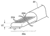
- the cross-sectional shape of the blade 22 in the direction orthogonal to the axial direction of the blade tip 22a has two flat portions 22a1 and semicircular portions 22a2 at both ends of the two flat portions 22a1.
- the blade tip 22a has a thin flat plate-like flat portion with a flat cross section.
- the plate-like width L1 is, for example, 0.3 to 0.9 mm
- the plate-like thickness L2 is, for example, 0.1 to 0.2 mm.
- a curved surface portion 22b having a semicircular cross-sectional shape along the axial direction of the blade 22 is provided at the tip of the blade tip portion 22a. Furthermore, the plane portion 22a1 is subjected to ultrasonic reflection processing for reflecting ultrasonic waves.
- a large number of fine grooves 22 ⁇ / b> A are formed in the two plane portions 22 a 1 as ultrasonic reflection processing portions.
- the numerous grooves 22A of the ultrasonic reflection processing portion are formed in a range in which the blade tip portion 22a is curved in a bow shape and is orthogonal to the axial direction of the blade tip portion 22a.
- the shape may contribute to the bending of the blade tip 22a.
- the width L1 of the blade tip 22a is narrower than the width L3 of the opening 21c of the needle tube 21, and, as will be described later, when the blade tip 22a is curved, the curved portion can protrude from the opening 21c.
- the blade tip 22a and the opening 21c are configured.
- a curved portion formed when the blade tip 22a protrudes from the opening 21c constitutes a cutting portion. That is, the cutting part is a curved part that is exposed from the opening 21c in a curved state when the tip of the blade tip 22a hits the tip of the opening 21c when the blade 22 protrudes from the opening 21c.
- the blade 22 can be inserted into the channel of the needle tube 21, and when the blade 22 is inserted through the channel, a curved portion serving as a cutting portion can project from the opening 21c.
- the needle tube distal end portion 21b is subjected to ultrasonic reflection processing over a predetermined range from the distal end portion of the opening 21c to the proximal end portion.
- the dimple processing of the plurality of dimples 21A is performed as the ultrasonic reflection processing portion over the range L4 where the opening 21c exists on the outer surface of the needle tube distal end portion 21b.
- the ultrasonic reflection process part of the several dimple 21A is formed over the range L4 in which the opening part 21c exists here, a dimple process is carried out between the front-end
- the ultrasonic reflection processing portion may be provided only at two positions, that is, the distal end portion of the opening portion 21c and the proximal end portion of the opening portion 21c.
- the inner wall portion 21e on the distal end side of the needle tube distal end portion 21b that forms the internal space 21d has an inclined surface that is inclined at a predetermined angle with respect to a surface orthogonal to the axial direction of the needle tube 21.
- the wall surface of the distal end side inner wall portion 21e is an inclined surface that approaches the proximal end direction of the needle tube 21 from the distal end portion 21d1 of the internal space 21d toward the opening portion 21c.
- the wall surface of the distal end side inner wall portion 21e is a slope that approaches the distal end portion of the needle tube 21 from the opening portion 21c toward the back of the internal space 21d.
- the needle tube distal end portion 21b has a sharp cross section on the puncture portion side of the opening portion 21c so that the blade distal end portion 22a does not jump out of the opening portion 21c when the curved portion of the blade distal end portion 22a is formed. It has such an inclined surface.
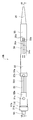
- FIG. 6 is an external view of the puncture tool operation unit 9B.
- FIG. 7 is a cross-sectional view of the puncture tool operation unit 9B along the line VII-VII in FIG.
- the puncture tool operation unit 9B is mounted and fixed to the treatment instrument insertion port 12a of the ultrasonic endoscope 2. At the distal end portion of the puncture tool operation portion 9B, a connection portion 31 for mounting on the treatment instrument insertion port 12a is provided. Furthermore, the puncture tool operation unit 9B includes a main body 32, a needle tube slider 33, a needle tube rotation operation unit 34, a blade slider 35, and a bend preventing unit 36 that protects the cable 9a in order toward the proximal end side.
- connection part 31 has a connection ring 31a and a tip connection member 31b on the tip side.
- the distal end connecting member 31b is inserted into the treatment instrument insertion port 12a, the connection portion 31 is mounted on the treatment instrument insertion port 12a of the endoscope operation unit 12, and the connection ring 31a is rotated in a predetermined direction.
- the puncture tool operation unit 9B can be fixed to the endoscope operation unit 12.
- a sheath fixing knob 31 c is provided on the proximal end side of the connection portion 31.
- a connecting member 32 a is provided on the front end side of the main body 32.
- the sheath 41 of the puncture instrument insertion portion 9A is externally inserted and fixed to a connection pipe 32b provided at the tip of the connection member 32a.
- the connecting member 32a is loosely fitted in the cylindrical connecting portion 31, and the sheath 41 can be fixed to the connecting portion 31 at a desired position by turning the sheath fixing knob 31c in a predetermined direction.
- a stopper 32c is provided on the distal end side of the connection member 32a so as to prevent the connection member 32a from coming out of the connection portion 31 by hitting the inner peripheral side convex portion of the cylindrical connection portion 31.
- a main body groove 32 d is formed on the outer surface of the main body 32 along the axial direction of the main body 32.
- a connecting member 33 a is provided on the distal end side of the needle tube slider 33.
- a stopper 32e is provided on the proximal end side of the main body 32 so as to prevent the main body 32 from coming out of the needle tube slider 33 by hitting the convex portion on the inner peripheral side of the cylindrical connecting member 33a.
- the connecting member 33a is provided with a needle tube fixing knob 33b.
- the main body 32 is loosely fitted in a cylindrical needle tube slider 33 on the proximal end side, and the needle tube slider 33 is fixed to the main body 32 at a desired position by turning the needle tube fixing knob 33b in a predetermined direction. can do.
- a cylindrical needle tube rotation operation portion 34 is provided to engage with the needle tube slider 33 so as to be rotatable around the axis of the needle tube rotation operation portion 34.
- Two blade adjustment grooves 34 a are provided on the outer surface of the needle tube rotation operation unit 34 along the axial direction of the needle tube rotation operation unit 34. Furthermore, each blade adjusting groove 34a is provided with a plurality of (here, four) concave portions 34b at predetermined intervals along the axial direction.
- the needle tube 21 is inserted into the sheath 41 of the puncture device insertion portion 9A, and the blade 22 is inserted into the needle tube 21.
- the proximal end portion of the needle tube 21 is fixed to the distal end portion of the needle tube rotation operation unit 34. Therefore, when the needle tube rotation operation unit 34 is rotated about the axis, the needle tube 21 is also rotated about the axis.
- a cylindrical blade slider 35 is externally provided on the proximal end side of the needle tube turning operation unit 34.
- Two engaging portions 35b sandwiched between two grooves 35a formed along the axial direction are provided on the tip side of the blade slider 35.
- the engaging portion 35b is provided with two protruding portions 35c protruding inward and a stopper 35d protruding inward.
- the two convex portions 35c engage with the two blade adjustment grooves 34a, and each convex portion 35c presses the outer surface of the blade adjustment groove 34a, and is movable along the axial direction of the needle tube turning operation portion 34.
- the blade slider 35 is formed.
- the blade slider 35 is provided with a cylindrical blade fixing base 35e fixed to the base end side.
- the base end of the blade 22 is inserted from the front end side of the blade fixing base 35e, the signal line of the cable 9a is inserted from the rear end side, and the blade 22 and the cable 9a are soldered by the solder 35f. It is fixed. Therefore, the blade 22 is fixed to the blade slider 35 by the blade fixing base 35e and is electrically connected to the cable 9a. That is, the cable 9a and the connector 9a1 connected to the blade 22 constitute a power supply connection portion for electrically connecting the blade tip portion 22a that is a cutting portion of the blade 22 and the high-frequency power supply device 8 that is a power source. .
- the stopper 35 d is a stopper for preventing the blade slider 35 from coming out of the needle tube turning operation unit 34 by hitting the outer peripheral side convex portion of the needle tube turning operation unit 34.
- the blade slider 35 is moved to the proximal end side so that the stopper 35d exceeds the outer peripheral convex portion of the needle tube turning operation unit 34 so that the engaging portion 35b is separated from the surface of the needle tube turning operation unit 34. Then, the blade slider 35 can be removed from the needle tube turning operation portion 34 and the blade 22 can be pulled out from the needle tube 21.
- a slight taper (luer taper) is provided in the opening 34c at the base end of the needle tube turning operation portion 34, which is exposed when the blade slider 35 is pulled out, so that the syringe 16 can be attached. .
- the opening 34 c at the proximal end of the needle tube turning operation unit 34 constitutes a suction device connecting portion for connecting the syringe 16 that is a suction device arranged on the proximal end side of the channel of the needle tube 21.
- the cable 9b extends from the side surface portion of the needle tube slider 33, and a bend preventing portion 36A is provided on the needle tube slider 33 so as to protect the periphery of the cable 9b.
- the distal end portion of the cable 9b is pressed against the needle tube 21 by the binder 33c as a fixing member, and the distal end portion of the cable 9b is fixed to the needle tube 21 by applying an adhesive 33d around the binder 33c. .
- the signal line of the cable 9b is soldered to the needle tube 21 with solder 33e inside the needle tube slider 33.
- the connector 9b1 for connecting to the high frequency power supply device 8 is provided at the base end of the cable 9b.
- the cable 9b and the connector 9b1 connected to the needle tube tip 21b having the puncture portion electrically connect the needle tube tip 21b having the conical portion 21a that is the puncture portion and the high-frequency power supply device 8 that is the power source.
- the power supply connection part for doing is comprised.
- the surgeon operates the puncture tool operation unit 9B to puncture the puncture tool inserted into the treatment instrument insertion channel of the ultrasonic endoscope 2.
- Each of the sheath 41, the needle tube 21, and the blade 22 of the instrument insertion portion 9A can be protruded and retracted from the treatment instrument opening of the distal end hard portion 14 of the endoscope insertion portion 11.
- FIGS. 6 and 7 show a state in which the sheath 41, the needle tube 21 and the blade 22 are drawn to the most proximal side of the puncture device insertion portion 9A.
- the puncture tool 9 is attached to the treatment instrument insertion port 12a, and in the state shown in FIGS. 6 and 7, the sheath 41, the needle tube 21 and the blade 22 are removed from the treatment instrument opening of the distal end hard portion 14 of the endoscope insertion portion 11. It does not protrude.
- FIG. 8 is a cross-sectional view of the puncture tool operation unit 9B in a state in which the sheath 41 protrudes most from the treatment instrument opening of the distal end rigid portion 14.
- FIG. 9 is a cross-sectional view of the puncture device operation unit 9B in a state in which the sheath 41 and the needle tube 21 protrude most from the treatment device opening of the distal end hard portion 14.
- FIG. 10 is a cross-sectional view of the puncture tool operation unit 9B in a state where the sheath 41 and the needle tube 21 protrude most from the treatment tool opening of the distal end hard portion 14 and the blade 22 protrudes from the treatment tool opening of the distal end hard portion 14 by one step. is there.
- FIG. 11 is a cross-sectional view of the puncture tool operation unit 9B in a state in which the sheath 41 and the needle tube 21 protrude most from the treatment instrument opening of the distal end hard portion 14, and the blade 22 protrudes most from the treatment instrument opening of the distal end hard portion 14.
- the blade tip 22a When the puncture tool operation unit 9B is in the state shown in FIG. 10, the blade tip 22a is curved, and the curved part protrudes from the opening 21c.
- the puncture tool operation portion 9B When the puncture tool operation portion 9B is in the state shown in FIG. 11, the blade tip 22a is further curved, and the curved portion, which is a cutting portion, further protrudes from the opening 21c.
- the surgeon operates each part of the puncture tool operation unit 9B, so that the sheath 41, the needle tube 21, and the blade 22 at the distal end of the puncture tool insertion part 9A are desired from the treatment instrument opening of the distal hard part 14. And can be drawn into the treatment instrument opening of the distal end hard portion 14.
- the curved surface portion 22b having a semicircular cross section comes into contact with the front end side inner wall portion 21e.
- the curved surface portion 22b moves along the inclined surface of the front end side inner wall portion 21e and comes into contact with the front end portion 21d1 of the internal space 21d. Curved to protrude from 21c.
- FIG. 12 is a cross-sectional view showing a state in which the blade tip 22a abuts against the tip 21d1 of the internal space 21d, but the blade tip 22a is not curved.
- FIG. 13 is a cross-sectional view showing a state where the blade tip 22a is in contact with the tip 21d1 of the internal space 21d, the blade 22 is further pushed out toward the tip, and the blade tip 22a is curved.
- the protrusion amount L5 of the blade tip 22a changes according to the amount of movement of the blade slider 35 toward the tip of the needle tube turning operation unit 34. And each position of the recessed part 34b respond
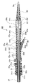
- FIG. 14 is a schematic explanatory diagram of the human body including the pancreas and stomach.
- the surgeon inserts the endoscope insertion portion 11 from the mouth M of the human body through the esophagus E to the stomach S.
- the pancreas P exists in the vicinity of the stomach S.
- Around the stomach S are a liver L and a gallbladder B.
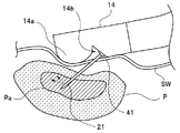
- FIG. 15 is a diagram for explaining the flow of a procedure for reducing the tumor part Pa, which is a lesioned part of the pancreas P.
- the operator SG inserts the distal end portion of the endoscope insertion portion 11 from the mouth M of the patient PA through the esophagus E as shown in FIG.
- the surgeon SG brings the ultrasonic vibration part 14a at the tip of the endoscope insertion part 11 into close contact with the stomach wall of the stomach S, and pierces the tumor part Pa under the ultrasonic guide (S1). That is, the surgeon SG operates the main body 32 and the needle tube slider 33 of the puncture tool operation unit 9B while viewing the ultrasonic image displayed on the monitor 7 to cause the needle tube 21 to protrude, and the tumor part Pa of the pancreas P.
- the needle tube 21 can be pierced.
- the operator peels the tumor tissue thinly with the blade 22 housed in the needle tube 21 under the ultrasonic guide (S2).
- the surgeon projects the blade tip 22 a while checking the protruding state of the curved portion of the blade tip 22 a, and supplies a high frequency current to the blade 22.
- the tumor tissue can be peeled off by gradually rotating around the axis of the needle tube 21.
- FIG. 16 is a diagram for explaining the protruding state of the blade tip 22a.
- the needle tube distal end portion 21 b penetrates the stomach wall SW and enters the tumor portion Pa of the pancreas P.
- the protruding amount L5 of the curved blade tip 22a from the opening 21c can be adjusted according to the amount of movement of the blade slider 35 relative to the needle tube turning operation unit 34.
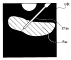
- FIG. 17 is a diagram illustrating an example of an ultrasonic image displayed on the monitor 7.
- the ultrasonic image USI obtained by the ultrasonic vibration unit 14a is displayed.
- the image 21bx of the needle tube tip 21b and the image 22ax of the blade tip 22a are clearly displayed in the ultrasonic image USI by the ultrasonic reflection processing portion provided on the surfaces of the needle tube tip 21b and the blade tip 22a.
- the image Pax of the tumor part Pa is also displayed in the ultrasonic image USI.
- the surgeon SG can grasp the position of the needle tube tip 21b and the protrusion amount of the blade tip 22a while viewing the ultrasonic image USI. Then, the operator SG positions the protruding blade tip 22a under the ultrasonic guide at a position where the inside of the tumor part Pa can be scraped off, and causes the needle tube 21 to flow while supplying a high-frequency current to the blade 22. By turning around the axis, the tumor tissue of the tumor part Pa can be peeled off by the curved part of the blade tip part 22a which is a cutting part.
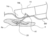
- FIG. 18 is a diagram for explaining the movement of the blade tip 22a.
- the operator moves the inside of the tumor part Pa as indicated by the dotted line R1 while rotating the needle tube 21 around the axis as indicated by the arrow A2.
- a high-frequency current flows through the blade 22. Therefore, the curved portion of the blade tip 22a scrapes the tumor tissue like an electric knife. Can be exfoliated into small tumor tissue pieces.
- the inside of the tumor part Pa is moved as indicated by the dotted line R1 while rotating the needle tube 21 around the axis, one tumor part Pa is decomposed into a large number or a plurality of fine tumor tissue pieces. .
- the surgeon can determine the degree of detachment of the tumor tissue in the tumor portion Pa, that is, how much the tumor tissue has been removed, by looking at the ultrasonic image USI.
- the tumor tissue is peeled so as to leave only a thin portion on the outer surface of the tumor part Pa. That is, the surgeon does not remove the normal tissue of the pancreas P around the tumor part Pa, but looks at the ultrasound image until the entire tumor tissue is removed so as to leave the outer layer of the tumor part Pa. And exfoliate the tumor tissue pieces. In addition, only the desired area
- the operator SG injects physiological saline or ethanol through the needle tube distal end portion 21b into the tumor portion Pa under an ultrasonic guide (S3).
- the surgeon puts physiological saline or ethanol in the syringe body of the syringe 16.
- the operator SG removes the blade slider 35 of the puncture device 9 from the needle tube rotation operation unit 34, pulls out the blade 22 from the needle tube 21, and rotates the needle tube from which the blade slider 35 is pulled out.
- a syringe 16 containing physiological saline or ethanol is attached to the opening 34c at the proximal end of the operation unit 34, and the plunger of the syringe 16 is pushed in, whereby physiological saline or ethanol is injected.
- FIG. 19 is a diagram for explaining injection of physiological saline or ethanol.
- the operator SG injects physiological saline or ethanol from the syringe 16
- the physiological saline or ethanol is injected into the outer layer of the tumor part Pa from the opening 21c as shown by a dotted line in FIG.
- the tumor part Pa swells and increases in volume.
- the surgeon SG can see the state of injection of physiological saline or ethanol by the ultrasonic image displayed on the monitor 7.
- FIG. 20 is a diagram showing an example of an ultrasonic image displayed on the monitor 7 when physiological saline or ethanol is injected. As shown in FIG. 20, an image Pax of the swollen tumor part Pa is displayed on the monitor 7. Therefore, the operator SG can inject a desired amount of physiological saline or ethanol into the tumor portion Pa while viewing the ultrasonic image.
- the surgeon SG collects the detached tumor tissue pieces together with physiological saline or ethanol under an ultrasonic guide (S4).
- the removed tumor tissue piece is collected by operating the syringe 16.
- FIG. 21 is a diagram for explaining the recovery of the detached tumor tissue piece.
- the detached tumor tissue piece is sucked from the opening 21c together with physiological saline or ethanol, and the tumor part The volume of Pa becomes small. That is, when physiological saline or ethanol is injected into the tumor site Pa in S3, fine fragments of the detached tumor tissue are contained in the physiological saline or ethanol. Therefore, when the peeled tumor tissue is sucked together with physiological saline or ethanol by the syringe 16, the size of the tumor part Pa is reduced.
- FIG. 22 is a diagram illustrating an example of an ultrasonic image displayed on the monitor 7 when a detached tumor tissue piece is collected. As shown in FIG. 22, a reduced image Pax of the tumor part Pa is displayed on the monitor 7.
- the needle tube 21 is pulled out from the tumor portion Pa while a high-frequency current is passed through the needle tube 21 (S5). Since a high-frequency current flows through the needle tube 21, the living tissue that comes into contact with the outer surface of the needle tube 21 is burned by the high-frequency current, so that attachment of living lesion cells can be prevented.
- the peeled tumor tissue in the tumor part Pa can be sucked and the size of the tumor part Pa of the pancreas P can be reduced.
- the pressure on peripheral organs, blood vessels, nerves and the like caused by Pa can be reduced or eliminated. Pain caused by compression based on tumor enlargement is reduced, and quality of life is improved.
- the peeled tumor tissue is aspirated, there is an effect of suppressing tumor collapse syndrome caused by cancer cells remaining in the body.
- the tumor part Pa since the size of the tumor part Pa is reduced and the tumor part Pa is separated from the surrounding blood vessels and the like, a surgical operation is possible and the tumor part Pa may be excised.
- physiological saline or ethanol is injected.
- physiological saline or ethanol may be injected.
- an antiplasmin drug may be injected instead of physiological saline or ethanol after injecting plasmin.
- the counter electrode plate 15a is used to flow a high-frequency current.
- the surgical system does not use the counter electrode plate 15a, but generates a current between the blade tip portion 22a and the needle tube tip portion 21b.
- a flowing bipolar configuration may be employed.
- FIG. 23 is a plan view of the needle tube distal end portion 21b1 of the puncture device insertion portion 9A1 according to the first modification.
- a cross-sectional view of the distal end portion of the puncture instrument insertion portion 9A along the line III-III of the needle tube distal end portion 21b1 of Modification 1 is the same as FIG.
- the cross-sectional view of the distal end portion of the puncture instrument insertion portion 9A1 along the IV-IV line of the needle tube distal end portion 21b1 of the first modification is the same as FIG.
- FIG. 24 is a plan view of the needle tube distal end portion 21b2 of the puncture device insertion portion 9A2 according to the second modification.
- FIG. 25 is a sectional view taken along line XXV-XXV in FIG.
- a cross-sectional view of the distal end portion of the puncture instrument insertion portion 9A2 along the IV-IV line of the needle tube distal end portion 21b2 of Modification 2 is the same as FIG.
- the blade tip portion 22a has a plate shape, but may have a plate shape having an axial extension portion 22a11 at the tip portion.
- FIG. 26 is a perspective view of the blade tip 22a of the third modification.
- the extension 22a11 extends toward the opposite side in a direction orthogonal to the axial direction of the blade tip 22a.
- the extension portion 22a11 is formed such that the length L11 of the shaft-like extension portion 22a11 in the direction orthogonal to the axial direction is shorter than the inner diameter of the needle tube 21.
- the blade tip 22a is unlikely to jump out of the opening 21c. That is, the extended portion 22a11 restricts the movement of the blade tip portion 22a toward the side surface of the needle tube 21 after the tip of the blade tip portion 22a hits the tip of the opening portion 21c when the curved portion of the blade tip portion 22a is formed.
- the blade tip 22a constitutes a pop-out prevention unit for preventing the blade tip 22a from jumping out of the opening 21c.
- the blade tip 22a has a plate shape, but may have a plate shape having a spherical extended portion 22a12 at the tip.
- FIG. 27 is a perspective view of the blade tip 22a of the fourth modification.
- FIG. 28 shows a state where the spherical extended portion 22a12 of the blade tip 22a is in contact with the tip 21d1 of the internal space 21d, the blade 22 is further pushed out toward the tip, and the blade tip 22a is curved. It is sectional drawing shown.
- FIG. 29 is a cross-sectional view of the distal end portion of the puncture instrument insertion portion 9A along the line XXIX-XXIX in FIG.
- the spherical extension 22a12 is provided at the tip of the blade tip 22a.
- the expanded portion 22a12 is formed so that the diameter L12 of the spherical expanded portion 22a12 is shorter than the inner diameter of the needle tube 21. That is, the extended portion 22a12 restricts the movement of the blade tip 22a toward the side surface of the needle tube 21 after the tip of the blade tip 22a hits the tip of the opening 21c when the curved portion of the blade tip 22a is formed.
- the blade tip 22a constitutes a pop-out prevention unit for preventing the blade tip 22a from jumping out of the opening 21c.
- the blade tip portion 22a is unlikely to jump out of the opening 21c, and even if the blade tip portion 22a2 of the fourth modification has such a spherical extended portion 22a12, This has the same effect as the puncture device of the above-described embodiment.
- the high-frequency power supply device has two connectors: a connector 8 a for high-frequency current flowing through the blade 22 and a connector 8 b for high-frequency current flowing through the needle tube 21.
- the high frequency power supply device may have one connector.
- FIG. 30 is a configuration diagram showing a configuration of a surgical system 1A using the ultrasonic endoscope according to the fifth modification.
- the high frequency power supply device 8A is provided with only a connector 8a for connecting to the puncture device 9X.
- the puncture device operation unit 9BX of the puncture device 9X includes a switch 9c that is a switch lever for supplying a high-frequency current to either the needle tube 21 or the blade 22. Therefore, the surgeon can supply the high-frequency current from the high-frequency power supply device 8 ⁇ / b> A to the needle tube 21 or the blade 22 by operating and switching the switch 9 c.
- the switch 9c is electrically connected to the blade tip portion 22a that is a cutting portion and the high-frequency power device 8 that is a power source, the needle tube tip portion 21b that has a puncture portion, and the electric power between the high-frequency power device 8 that is a power source.
- FIG. 31 is an external view of a puncture device operation unit 9BX according to the fifth modification.
- FIG. 32 is a cross-sectional view of the puncture tool operation unit 9B taken along line XXXII-XXXII in FIG.
- the puncture tool operation unit 9BX has substantially the same configuration as the puncture tool operation unit 9B of the first embodiment described above, and the same components are denoted by the same reference numerals and description thereof is omitted.
- the puncture tool operation unit 9BX extends on the proximal end side of the blade slider 35, and a switch 9c is provided on the extension unit 35A.
- a D-cut portion 22X having a D-shaped cross section is formed at the base end portion of the blade tip portion 22a.
- the proximal end portion of the needle tube 21 is provided with a needle tube extending portion 21X extending toward the proximal end, and a curved contact portion 21Xa is formed at the proximal end portion of the needle tube extending portion 21X.
- the D-cut portion 22X of the blade 22 is provided with an insulator 51a having a long and thin electrode portion 51 on the surface at a position where the contact portion 21Xa comes into contact.
- the electrode part 51 is formed along the axial direction of the blade 22.
- the base end side of the electrode part 51 on the surface of the insulator 51a is connected to one end of the conducting wire 52 by solder 35f.
- the other end of the conducting wire 52 is connected to one switch terminal 54a of the switch body 53 provided in the extending portion 35A through a hole formed in the blade slider 35 and the extending portion 35A.
- the base end portion of the blade 22 is connected to one end of the conducting wire 55 by solder 35f in the blade fixing base 35e.
- the other end of the conducting wire 55 is connected to one switch terminal 54b of the switch body 53 provided in the extending portion 35A.
- the signal line of the cable 9 a is connected to one switch terminal 54 c of the switch body 53.
- the contact portion 21Xa of the needle tube 21 slides along the electrode portion 51 while contacting the electrode portion 51 formed on the surface of the insulator 51a. To do. Further, in the switch main body 53, the switch 9c is operated so that the switch terminal 54a and the switch terminal 54c are electrically connected, or the switch terminal 54b and the switch terminal 54c are electrically connected.
- surgeon can switch between supplying the high frequency current from the high frequency power supply device 8A to the blade 22 or the needle tube 21 by operating the switch 9c.
- the surgery system 1A of the fifth modification also has the same effect as the puncture device of the above-described embodiment.
- the lesion part is reduced by reaching the inside of the lesion part and scraping the inside thereof, In addition, it is possible to prevent attachment of living lesion cells when they are removed from the lesion.
- the puncture device is configured to scrape the inside of the lesioned part by rotating the blade to which a high-frequency current is applied. Without applying a high-frequency current, the inside of the lesion is scraped off by the blade provided on the blade.
- the configuration of the puncture device, ultrasonic endoscope, and surgical system of the present embodiment is substantially the same as the configuration of the puncture device, ultrasonic endoscope, and surgical system of the first embodiment described above, and the same configuration About the element, description is abbreviate
- the puncture device of the present embodiment has a needle tube tip portion 21b having a conical puncture portion as shown in FIGS. Furthermore, the puncture device of the present embodiment is configured such that the blade tip portion has a blade portion, and the inside of the lesioned portion is scraped by the blade portion when the blade rotates. Therefore, the blade is not energized when scraping the inside of the lesioned part. Therefore, the high-frequency power supply device 8 has a connector for flowing a high-frequency current to the needle tube when the needle tube is removed, but there is no connector for flowing a high-frequency current to the blade, and the puncture device applies a high-frequency current to the blade. There is no cable to flow.
- FIG. 33 is a cross-sectional view of the distal end portion of the puncture tool when the needle tube distal end portion 21b is cut along a plane orthogonal to the axial direction of the needle tube 21 according to the present embodiment.
- the blade tip portion 22a is formed with a blade portion 61 along the axial direction. Therefore, when the blade portion 61 is applied to the tumor tissue and the needle portion rotation operation portion 34 is rotated so as to scrape off the tumor tissue, the tumor tissue is peeled off by the blade portion 61. That is, the blade portion 61 of the curved portion formed when the blade tip portion 22a protrudes from the opening portion 21c constitutes a cutting portion.
- FIG. 34 is a cross-sectional view of the distal end portion of a modified example of the puncture tool when the needle tube distal end portion 21b is cut along a plane orthogonal to the axial direction of the needle tube 21 when the blade distal end portion 22a is provided with two blade portions.
- FIG. The blade part 62 is formed along a side part opposite to the blade part 61. According to such a configuration, there is an effect that the surgeon does not have to be aware of the side where the blade portion is present in the blade tip portion 22a.
- FIG. 35 is a cross-sectional view of puncture tool operation unit 9B1 along the axial direction according to the present embodiment.
- the blade 22 is connected so as to be electrically connected to the cable 9a in the puncture tool operation unit 9B.
- the base end of the blade 22 is connected to the cable 9a.
- the high frequency power supply apparatus may have only one connector as shown in FIG.
- the treatment with the puncture device and the ultrasonic endoscope of the present embodiment is the same as the first embodiment except that the tumor tissue is peeled off without energizing the blade 22. That is, under the ultrasonic guide, the needle tube 21 is stabbed into the tumor part Pa (S1), the tumor tissue is peeled off by the blade part 61 (or 62) described above (S2), the blade 22 is removed from the needle tube, and the ultrasonic wave is removed. Under the guide, physiological saline or ethanol is injected into the tumor site Pa (S3), and the detached tumor tissue is collected together with the physiological saline or ethanol under the ultrasonic guide (S4). Then, the needle tube 21 is pulled out from the tumor tissue while applying a high-frequency current to the needle tube 21 (S5).
- a hemostatic effect can be obtained by performing a procedure for removing the tumor tissue while injecting ethanol. Furthermore, the proximal end portion of the blade 22 is connected to an ultrasonic transducer so that the blade 22 is vibrated by ultrasonic vibration so that the blade portion 61 (and 62) peels off the tumor tissue of the tumor portion Pa. It may be. In this case, ultrasonic vibration may be applied while injecting ethanol into the tumor site Pa.
- the blade 61 (and 62) is used to squeeze out the tumor tissue in the tumor part Pa, reduce the tumor part Pa, and pull out the needle tube 21 from the lesioned part while flowing high-frequency current through the needle tube 21. It can prevent the attachment of living lesion cells.
- the puncture device according to the third embodiment like the blade according to the second embodiment, does not energize the blade with high-frequency current, and scrapes the inside of the lesioned portion with the blade provided on the blade. It is configured as follows. However, in the puncture device of the third embodiment, the blade tip does not curve from the opening of the needle tube tip, but the blade projects obliquely with respect to the axial direction of the needle tube tip, and the blade tip It is comprised so that the inside of a lesioned part may be scraped off by the blade part provided in.
- the configuration of the puncture device, ultrasonic endoscope, and surgical system of the present embodiment is substantially the same as the configuration of the puncture device, ultrasonic endoscope, and surgical system of the second embodiment described above.
- description is abbreviate
- the puncture device of the present embodiment is configured such that the blade tip portion has a blade portion and the inside of the lesioned portion is scraped off by the blade portion when the blade rotates. Therefore, the blade is not energized when scraping the inside of the lesioned part. Therefore, the high-frequency power supply device 8 has a connector for flowing a high-frequency current to the needle tube when the needle tube is removed, but there is no connector for flowing a high-frequency current to the blade, and the puncture tool also applies a high-frequency current to the blade. There is no cable to flow.
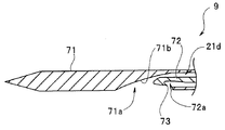
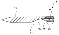
- FIG. 36 is a plan view of the needle tube tip 71 according to the present embodiment.
- FIG. 37 is a cross-sectional view of the needle tube tip 71 taken along the line XXXVII-XXXVII in FIG.
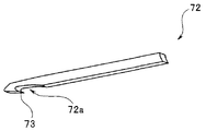
- FIG. 38 is a perspective view of the blade tip according to the present embodiment.
- FIG. 39 is a cross-sectional view of the needle tube tip 71 when the blade tip protrudes from the opening.
- the needle tube tip 71 of the needle tube 21 has a conical tip. On the distal end side of the inner space 21d of the needle tube distal end portion 71, an inclined portion 71d having a gentle inclined surface toward the opening 71a is provided.
- the blade tip 72 of the blade 22 inserted into the internal space 21d of the needle tube 21 has a recess 72a on the tip side, and a blade 73 on the tip side of the recess 72a. Is formed.
- the blade distal end portion 72 has a bowl shape, and the cutting edge of the blade portion 73 at the bowl shaped distal end is formed toward the proximal end side. That is, the blade portion 73 constitutes a cutting portion.
- the ultrasonic reflection processing is applied only to the peripheral portion of the recess 72a at the blade tip 72, although not shown. Further, in the needle tube distal end portion 71, as will be described later, the blade distal end portion 72 protrudes from the opening 71a along the axial direction of the needle tube distal end portion 71 and spans a range in which the tumor tissue can be separated. Dimple processing is applied to the surface of the tip 71 of the needle tube as an ultrasonic reflection processing portion.
- the blade 22 is moved or the needle tube 21 is moved so that the blade tip 72 protrudes from the opening 71a and the blade tip 72 moves back and forth along the axial direction.
- the tumor tissue in the tumor part Pa can be peeled off as if it is scraped off by the blade part 73.
- the treatment with the puncture device and the ultrasonic endoscope of the present embodiment is the same as the first embodiment except that the tumor tissue is peeled off without energizing the blade 22. That is, under the ultrasonic guide, the needle tube tip 71 is stabbed into the tumor Pa (S1), the tumor tissue is peeled off by the blade 73 described above (S2), the blade tip 72 is removed from the needle tube 21, Under the sonic guide, physiological saline or ethanol is injected into the tumor part Pa (S3), and under the ultrasonic guide, the detached tumor tissue is collected together with the physiological saline or ethanol (S4). Then, the needle tube 21 is pulled out from the tumor tissue while applying a high-frequency current to the needle tube 21 (S5).
- a hemostatic effect can be obtained by performing a procedure for removing the tumor tissue while injecting ethanol. Therefore, the living lesion when the needle tube 21 is pulled out from the lesioned part while the tumor part Pa is shrunk by the blade part 73 to reduce the tumor part Pa and a high-frequency current flows through the needle tube 21. Cell adhesion can be prevented.
- FIG. 40 is a cross-sectional view along the axial direction of the distal end portion of the needle tube according to a modification of the third embodiment.
- FIG. 41 is a cross-sectional view of the distal end portion of the needle tube along the axial direction of the needle tube when the distal end portion of the blade in FIG. 40 protrudes from the opening.
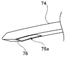
- FIG. 42 is a perspective view from the upper surface side of the blade tip 74 of the blade 22.
- FIG. 43 is a perspective view from the lower surface side of the blade tip 74.
- the blade tip portion 74 of this modification has a hole 75 formed on the tip side, and a blade portion 76 is provided in one opening 75a on the tip side of the hole 75. It has been.
- the blade portion 76 is formed toward the proximal end side. That is, the blade portion 76 constitutes a cutting portion.
- the ultrasonic reflection processing is applied only to the peripheral portion of the opening 75 a where the blade 76 is provided at the blade tip 74.
- the puncture device 9 of the present modification the blade tip 74 is protruded from the opening 71a, and the blade 22 is moved or the needle tube 21 is moved so that the blade tip 74 is advanced and retracted along the axial direction.
- the tumor tissue in the tumor part Pa can be peeled off by scraping with the blade part 76.
- the configurations of the first to fourth modifications of the first embodiment can also be applied to the present embodiment.
- the lesioned part is punctured by the lesioned part and scraped off the inside of the lesioned part. It can be reduced, and attachment of living lesion cells can be prevented when removing from the lesion. Furthermore, since the size of the tumor can be reduced and attachment of living lesion cells can be prevented, an operation for excision of the tumor can be performed immediately thereafter.
- high-frequency current is supplied to the needle tube to prevent attachment of living lesion cells when the needle tube 21 is pulled out from the lesioned part.
- high-frequency current may be applied when the needle tube 21 is pierced.
Landscapes
- Health & Medical Sciences (AREA)
- Life Sciences & Earth Sciences (AREA)
- Surgery (AREA)
- Engineering & Computer Science (AREA)
- Heart & Thoracic Surgery (AREA)
- Biomedical Technology (AREA)
- Public Health (AREA)
- Medical Informatics (AREA)
- Molecular Biology (AREA)
- Veterinary Medicine (AREA)
- Animal Behavior & Ethology (AREA)
- General Health & Medical Sciences (AREA)
- Nuclear Medicine, Radiotherapy & Molecular Imaging (AREA)
- Physics & Mathematics (AREA)
- Pathology (AREA)
- Radiology & Medical Imaging (AREA)
- Biophysics (AREA)
- Plasma & Fusion (AREA)
- Otolaryngology (AREA)
- Vascular Medicine (AREA)
- Orthopedic Medicine & Surgery (AREA)
- Cardiology (AREA)
- Surgical Instruments (AREA)
- Ultra Sonic Daignosis Equipment (AREA)
Abstract
Description
なお、以下の説明に用いる各図においては、各構成要素を図面上で認識可能な程度の大きさとするため、構成要素毎に縮尺を異ならせてあるものであり、本発明は、これらの図に記載された構成要素の数量、構成要素の形状、構成要素の大きさの比率、及び各構成要素の相対的な位置関係のみに限定されるものではない。
(手術システムの構成)
図1は、本第1の実施の形態に係わる超音波内視鏡を用いた手術システムの構成を示す構成図である。
また、図示しないが、先端硬質部14には、光源装置4からの照明光を出射する照明窓と、観察窓と、観察窓の後側に設けられた撮像素子と、超音波振動部14a(図15)が設けられている。すなわち、超音波内視鏡2は、穿刺具9に向けて超音波を送信し、穿刺具9から反射した超音波を受信する超音波観察部としての超音波振動部14aを有する。
高周波電源装置8は、2つのコネクタ8a、8bを有し、コネクタ8aには、コネクタ9a1が接続され、コネクタ8bには、コネクタ9b1が接続されている。ケーブル9aを介して穿刺具9のブレード22(図5)に高周波電流が供給され、ケーブル9bを介して穿刺具9の針管21(図2)に高周波電流が供給される。
ブレード22と針管21のそれぞれへの高周波電流の供給は、術者による、高周波電源装置8に設けられたスイッチ(図示せず)への操作により行うことができる。
穿刺具9は、針管21とブレード22が挿通された細長い穿刺具挿入部9Aと、穿刺具挿入部9Aの基端側に設けられ、針管21などの突出操作を行うための穿刺具操作部9Bと、を有している。穿刺具挿入部9Aは、内視鏡操作部12の処置具挿通口12aから挿入され、内視鏡挿入部11内の処置具挿通チャンネルを通って、穿刺具挿入部9Aの先端部が先端硬質部14の処置具開口から突出可能に、穿刺具9は構成されている。
図2及び図3に示すように、針管21は、先端面の孔が溶接等により塞がれた、ステンレス、ニッケルチタン、コバルトクロム合金などの管状部材である。針管21は、先端側が側面で開口しているチャンネルを内部に有する管状部を構成する。中空で細長い針管21は、先端に尖った円錐形状部21aを有する針管先端部21bを有する。針管先端部21bには、軸方向に沿って形成された細長い開口部21cとを有する。開口部21cは、円錐形状部21aの近傍に設けられている。すなわち、開口部21cは、針管先端部21bの先端部の基端側に設けられ、針管21内のチャンネルに連通する。そして、円錐形状部21aは、管状部である針管21の先端面に配置され、被検体に穿刺するための穿刺部を構成する。針管21の直径は、例えば、22G~19G(ゲージ)である。開口部21cの軸方向の長さは、例えば、5~15mmである。すなわち、針管21は、先端が所謂ペンシル形状を有する。
針管先端部21bのチャンネル内側表面には、放電加工などにより表面を酸化させて接触抵抗を大きくして導電率を低下させる加工、あるいはポリイミドなどにより表面コーティングによる絶縁膜を形成する加工が施されている。
ブレードスライダ35が引き抜かれると露出する、針管回動操作部34の基端部の開口部34cには僅かなテーパ(ルアテーパ)を設けており、シリンジ16を装着することができるようになっている。すなわち、針管回動操作部34の基端部の開口部34cは、針管21のチャンネルの基端側に配置された吸引装置であるシリンジ16を接続するための吸引装置接続部を構成する。
上述した穿刺具9を用いた処置について説明する。ここでは、膵癌の病変部を縮小させる手技の例を説明する。
例えば、術者は、モニタ7に表示される超音波画像を見ながら、ブレード先端部22aの湾曲部の突出状態を確認しながら、ブレード先端部22aを突出させ、ブレード22に高周波電流を供給しながら、針管21の軸回りに少しずつ回動させて、腫瘍組織を剥離することができる。
そして、術者SGは、超音波ガイド下で、突出したブレード先端部22aを、腫瘍部Paの内部を削りとることができる位置に位置させて、ブレード22に高周波電流を流しながら、針管21を軸回りに回動させることによって、切削部であるブレード先端部22aの湾曲部により、腫瘍部Paの腫瘍組織を剥離することができる。
術者は、シリンジ16のシリンジ本体内に生理食塩水又はエタノールを入れておく。S2の後、術者SGは、上述したように、穿刺具9のブレードスライダ35を針管回動操作部34から外して、ブレード22を針管21から引き抜き、ブレードスライダ35が引き抜かれた針管回動操作部34の基端部の開口部34cに、生理食塩水又はエタノールを含むシリンジ16を装着し、シリンジ16のプランジャを押し込むことによって、生理食塩水又はエタノールの注入を行う。
また、剥離した腫瘍組織が吸引されているので、癌細胞などが体内に残ることによる腫瘍崩壊症候群の抑制になるという効果もある。
なお、S3では、生理食塩水又はエタノールを注入しているが、剥離した腫瘍組織を溶かすトリプシンを注入した後に、生理食塩水又はエタノールを注入してもよい。剥離した腫瘍組織に繊維質が多い場合は、プラスミンを注入した後に、生理食塩水又はエタノールの代わりに抗プラスミン薬を注入してもよい。
上述した実施の形態では、針管先端部21bの先端部は円錐形状であるが、トロッカポイント形状でもよい。
図23は、本変形例1係る穿刺具挿入部9A1の針管先端部21b1の平面図である。本変形例1の針管先端部21b1のIII-III線に沿った穿刺具挿入部9Aの先端部の断面図は、図3と同じである。本変形例1の針管先端部21b1のIV-IV線に沿った穿刺具挿入部9A1の先端部の断面図は、図4と同じである。
上述した実施の形態では、針管先端部21bの先端部は円錐形状であるが、べベルカット形状でもよい。
図24は、本変形例2係る穿刺具挿入部9A2の針管先端部21b2の平面図である。
上述した実施の形態、変形例1及び変形例2では、ブレード先端部22aは、板状形状であるが、先端部に、軸状の拡張部22a11を有する板状形状でもよい。
このような拡張部22a11を設けることによって、ブレード先端部22aは、開口部21cから飛び出し難い。すなわち、拡張部22a11は、ブレード先端部22aの湾曲部が形成されたときに、ブレード先端部22aの先端が開口部21cの先端にぶつかった後に針管21の側面方向に移動することを規制して、ブレード先端部22aが開口部21cから飛び出さないようにするための飛び出し防止部を構成する。
上述した実施の形態、変形例1及び変形例2では、ブレード先端部22aは、板状形状であるが、先端部に、球形の拡張部22a12を有する板状形状でもよい。
上述した実施の形態、変形例1から変形例4では、高周波電源装置は、ブレード22に流す高周波電流のためのコネクタ8aと、針管21に流す高周波電流のためのコネクタ8bの2つのコネクタを有しているが、高周波電源装置は、1つのコネクタを有するようにしてもよい。
穿刺具操作部9BXは、上述した第1の実施の形態の穿刺具操作部9Bと略同じ構成を有し、同じ構成要素については、同じ符号を付して説明は省略する。穿刺具操作部9BXは、ブレードスライダ35の基端側が延出しており、その延出部35Aにスイッチ9cが設けられている。
よって、本変形例5の手術システム1Aによっても、上述した実施の形態の穿刺具と同様の効果を有する。
第1の実施の形態の穿刺具は、高周波電流が通電されたブレードを回転することにより、病変部の内部を削り取るように構成されているが、本実施の形態の穿刺具は、ブレードには高周波電流を通電せずに、ブレードに設けられた刃部により、病変部の内部を削り取るように構成されている。
図33に示すように、ブレード先端部22aには、軸方向に沿って刃部61が形成されている。よって、刃部61を腫瘍組織にあてて、針部回動操作部34を、腫瘍組織を削り採るように回動させると、腫瘍組織は、刃部61により剥離される。すなわち、ブレード先端部22aが開口部21cから突出したときに形成される湾曲部の刃部61が、切削部を構成する。
このような構成によれば、術者は、ブレード先端部22aにおける刃部のある側を意識しないでよいという効果がある。
さらになお、ブレード22の基端部を超音波振動子に接続して、ブレード22を超音波振動により振動させるようにして、刃部61(及び62)により腫瘍部Paの腫瘍組織を剥離するようにしてもよい。この場合、腫瘍部Paにエタノールを注入しながら、超音波振動を与えてもよい。
本第3の実施の形態の穿刺具も、第2の実施の形態のブレードのように、ブレードには高周波電流を通電せずに、ブレードに設けられた刃部により、病変部の内部を削り取るように構成されている。但し、本第3の実施の形態の穿刺具では、針管先端部の開口部からブレード先端部が湾曲するのではなく、ブレードは、針管先端部の軸方向に対して斜め方向に突出し、ブレード先端に設けられた刃部により、病変部の内部を削り取るように構成されている。
針管先端部71の内部空間21dの先端側には、開口部71aに向かって緩やかな傾斜面を有する傾斜部71dが設けられている。
従って、刃部73により、腫瘍部Pa内の腫瘍組織を刳り抜くようにして、腫瘍部Paを縮小させ、かつ針管21に高周波電流を流しながら針管21を病変部から引き抜く際の生きている病変細胞の付着を防止することができる。
図40は、本第3の実施の形態の変形例に係る針管先端部の軸方向に沿った断面図である。図41は、図40のブレード先端部が開口部から突出したときの、針管の軸方向に沿った針管先端部の断面図である。図42は、ブレード22のブレード先端部74の上面側からの斜視図である。図43は、ブレード先端部74の下面側からの斜視図である。
本変形例の穿刺具9によれば、ブレード先端部74を開口部71aから突出させ、ブレード先端部74を軸方向に沿って進退させるように、ブレード22を動かす、あるいは針管21を動かすことによって、腫瘍部Pa内の腫瘍組織を、刃部76により削り取るようにして、剥離することができる。
なお、本実施の形態についても、第1の実施の形態の変形例1から4の各変形例の構成も適用可能である。
さらに、腫瘍の大きさを小さくしかつ生きている病変細胞の付着を防止できるので、その後直ぐに腫瘍部の切除のための手術を行うことができる。
本出願は、2012年12月12日に日本国に出願された特願2012-271651号を優先権主張の基礎として出願するものであり、上記の開示内容は、本願明細書、請求の範囲に引用されるものとする。
Claims (11)
- 先端側が側面で開口しているチャンネルを内部に有する管状部と、
前記チャンネルに連通するように前記管状部の基端側に配置され、吸引装置に接続される吸引装置接続部と、
前記管状部の先端面に配置され、被検体に穿刺するための穿刺部と、
前記穿刺部の側面に設けられた前記チャンネルの開口部と、
前記チャンネルに挿通可能であり、前記チャンネルに挿通されたときに前記開口部から切削部を突出可能なブレードと、
前記穿刺部と電源とを電気的に接続するための第1電源接続部と、
を有することを特徴とする穿刺具。 - 前記ブレードの前記切削部と前記電源とを電気的に接続するための第2電源接続部と、
を有することを特徴とする請求項1に記載の穿刺具。 - 前記ブレードの前記切削部と前記電源との電気的接続、および、前記穿刺部と前記電源との電気的接続、を切り替える切替部、
を有することを特徴とする請求項2に記載の穿刺具。 - 前記針管は、前記ブレードよりも電気抵抗が高いことを特徴とする請求項2に記載の穿刺具。
- 前記管状部は金属から成り、
前記チャンネルの内周には前記金属を酸化させた酸化層が配置されていることを特徴とする請求項4に記載の穿刺具。 - 前記切削部は、前記ブレードが前記開口部から突出する際に、前記切削部の先端が前記開口の先端にぶつかることで、湾曲した状態で前記開口から露出する湾曲部であることを特徴とする請求項1に記載の穿刺具。
- 前記ブレードは、前記湾曲部が形成されたときに、前記ブレードの先端が前記開口部から飛び出さないようにするため前記ブレードの先端が前記開口部の先端にぶつかった後に前記管状部の側面方向に移動することを規制する飛び出し防止部を有することを特徴とする請求項6に記載の穿刺具。
- 前記開口部の穿刺部側の端面は、前記湾曲部が形成されたときに、前記ブレードの先端が前記開口部から飛び出さないようにするため前記開口部の穿刺部側の断面が鋭角となるような傾斜面を有することを特徴とする請求項6に記載の穿刺具。
- 前記切削部は、前記ブレードの先端部に設けられた刃部であることを特徴とする請求項1に記載の穿刺具。
- 超音波反射加工が、前記開口部の周囲の前記穿刺部の表面、及び前記切削部の表面に施されていることを特徴とする請求項1に記載の穿刺具。
- 請求項1に記載の穿刺具と、
前記穿刺具に向けて超音波を送信し、前記穿刺具から反射した超音波を受信する超音波観察部と、
を含むこと特徴とする超音波内視鏡。
Priority Applications (4)
| Application Number | Priority Date | Filing Date | Title |
|---|---|---|---|
| CN201380041739.0A CN104519810B (zh) | 2012-12-12 | 2013-11-08 | 穿刺器具及超声波内窥镜 |
| JP2014520459A JP5642905B2 (ja) | 2012-12-12 | 2013-11-08 | 穿刺具及び超音波内視鏡 |
| EP13862066.1A EP2865345B1 (en) | 2012-12-12 | 2013-11-08 | Puncture tool and ultrasonic endoscope |
| US14/597,570 US20150126994A1 (en) | 2012-12-12 | 2015-01-15 | Puncture tool and ultrasound endoscope |
Applications Claiming Priority (2)
| Application Number | Priority Date | Filing Date | Title |
|---|---|---|---|
| JP2012271651 | 2012-12-12 | ||
| JP2012-271651 | 2012-12-12 |
Related Child Applications (1)
| Application Number | Title | Priority Date | Filing Date |
|---|---|---|---|
| US14/597,570 Continuation US20150126994A1 (en) | 2012-12-12 | 2015-01-15 | Puncture tool and ultrasound endoscope |
Publications (1)
| Publication Number | Publication Date |
|---|---|
| WO2014091846A1 true WO2014091846A1 (ja) | 2014-06-19 |
Family
ID=50934144
Family Applications (1)
| Application Number | Title | Priority Date | Filing Date |
|---|---|---|---|
| PCT/JP2013/080222 WO2014091846A1 (ja) | 2012-12-12 | 2013-11-08 | 穿刺具及び超音波内視鏡 |
Country Status (5)
| Country | Link |
|---|---|
| US (1) | US20150126994A1 (ja) |
| EP (1) | EP2865345B1 (ja) |
| JP (1) | JP5642905B2 (ja) |
| CN (1) | CN104519810B (ja) |
| WO (1) | WO2014091846A1 (ja) |
Cited By (2)
| Publication number | Priority date | Publication date | Assignee | Title |
|---|---|---|---|---|
| JP2018534017A (ja) * | 2015-10-28 | 2018-11-22 | ボストン サイエンティフィック サイムド,インコーポレイテッドBoston Scientific Scimed,Inc. | 格納式の組織切断デバイス |
| KR102046403B1 (ko) * | 2019-05-10 | 2019-11-19 | 이철중 | 후방디스크 접근법에 이용되는 니들 세트 |
Families Citing this family (6)
| Publication number | Priority date | Publication date | Assignee | Title |
|---|---|---|---|---|
| GB2567000B (en) | 2017-09-29 | 2020-03-04 | John Milton Trevor | A slidably operated flexible biopsy blade |
| US11207212B2 (en) * | 2018-03-30 | 2021-12-28 | Surgical Design Corporation | Phaco cone work tip for a surgical hand-piece |
| US11369513B2 (en) | 2017-11-22 | 2022-06-28 | Surgical Design Corporation | Low-cost disposable ultrasonic surgical handpiece |
| US11690757B2 (en) | 2018-03-30 | 2023-07-04 | Surgical Design Corporation | Surgical hand piece with post-occlusion surge elimination |
| US11504271B2 (en) | 2018-03-30 | 2022-11-22 | Surgical Design Corporation | Surgical hand-piece with a bottom fluid tube convertible from irrigation to aspiration |
| US20210000332A1 (en) * | 2019-07-03 | 2021-01-07 | Gyrus Acmi, Inc. | Real-Time Sampling Device |
Citations (3)
| Publication number | Priority date | Publication date | Assignee | Title |
|---|---|---|---|---|
| JP2000116657A (ja) | 1998-09-03 | 2000-04-25 | Rubicor Medical Inc | 切開生検装置および方法 |
| JP2002531211A (ja) * | 1998-12-09 | 2002-09-24 | セノークス・インコーポレイテッド | 組織標本閉じ込め装置およびその方法 |
| JP2004531290A (ja) * | 2000-12-07 | 2004-10-14 | ルビコー メディカル インコーポレイテッド | 高周波電気手術のための方法および器具 |
Family Cites Families (7)
| Publication number | Priority date | Publication date | Assignee | Title |
|---|---|---|---|---|
| US6514248B1 (en) * | 1999-10-15 | 2003-02-04 | Neothermia Corporation | Accurate cutting about and into tissue volumes with electrosurgically deployed electrodes |
| US20080103504A1 (en) * | 2006-10-30 | 2008-05-01 | Schmitz Gregory P | Percutaneous spinal stenosis treatment |
| US7850686B2 (en) * | 2006-03-30 | 2010-12-14 | Ethicon Endo-Surgery, Inc. | Protective needle knife |
| US20080051626A1 (en) * | 2006-08-28 | 2008-02-28 | Olympus Medical Systems Corp. | Fistulectomy method between first duct and second duct, ultrasonic endoscope, catheter with balloon, magnet retaining device, and magnet set |
| US20100063392A1 (en) * | 2008-09-08 | 2010-03-11 | Olympus Medical Systems Corp. | Ultrasound-guided ablation method and ultrasound-guided ablation system |
| CN201533858U (zh) * | 2009-11-24 | 2010-07-28 | 陈仁杰 | 多功能鼻腔手术用旋切刀 |
| US8579928B2 (en) * | 2010-02-11 | 2013-11-12 | Ethicon Endo-Surgery, Inc. | Outer sheath and blade arrangements for ultrasonic surgical instruments |
-
2013
- 2013-11-08 EP EP13862066.1A patent/EP2865345B1/en not_active Not-in-force
- 2013-11-08 CN CN201380041739.0A patent/CN104519810B/zh active Active
- 2013-11-08 WO PCT/JP2013/080222 patent/WO2014091846A1/ja active Application Filing
- 2013-11-08 JP JP2014520459A patent/JP5642905B2/ja active Active
-
2015
- 2015-01-15 US US14/597,570 patent/US20150126994A1/en not_active Abandoned
Patent Citations (3)
| Publication number | Priority date | Publication date | Assignee | Title |
|---|---|---|---|---|
| JP2000116657A (ja) | 1998-09-03 | 2000-04-25 | Rubicor Medical Inc | 切開生検装置および方法 |
| JP2002531211A (ja) * | 1998-12-09 | 2002-09-24 | セノークス・インコーポレイテッド | 組織標本閉じ込め装置およびその方法 |
| JP2004531290A (ja) * | 2000-12-07 | 2004-10-14 | ルビコー メディカル インコーポレイテッド | 高周波電気手術のための方法および器具 |
Non-Patent Citations (1)
| Title |
|---|
| See also references of EP2865345A4 |
Cited By (4)
| Publication number | Priority date | Publication date | Assignee | Title |
|---|---|---|---|---|
| JP2018534017A (ja) * | 2015-10-28 | 2018-11-22 | ボストン サイエンティフィック サイムド,インコーポレイテッドBoston Scientific Scimed,Inc. | 格納式の組織切断デバイス |
| US10376316B2 (en) | 2015-10-28 | 2019-08-13 | Boston Scientific Scimed, Inc. | Retractable tissue cutting device |
| KR102046403B1 (ko) * | 2019-05-10 | 2019-11-19 | 이철중 | 후방디스크 접근법에 이용되는 니들 세트 |
| WO2020231002A1 (ko) * | 2019-05-10 | 2020-11-19 | 이철중 | 후방디스크 접근법에 이용되는 니들 세트 |
Also Published As
| Publication number | Publication date |
|---|---|
| US20150126994A1 (en) | 2015-05-07 |
| JPWO2014091846A1 (ja) | 2017-01-05 |
| JP5642905B2 (ja) | 2014-12-17 |
| CN104519810A (zh) | 2015-04-15 |
| EP2865345A1 (en) | 2015-04-29 |
| EP2865345B1 (en) | 2016-12-28 |
| EP2865345A4 (en) | 2016-01-13 |
| CN104519810B (zh) | 2017-02-22 |
Similar Documents
| Publication | Publication Date | Title |
|---|---|---|
| JP5642905B2 (ja) | 穿刺具及び超音波内視鏡 | |
| US9655671B2 (en) | Endoscopic resection device | |
| US20080194999A1 (en) | Ultrasonic treatment apparatus and treatment method | |
| US20120265057A1 (en) | Ultrasound endoscope system and ultrasound observation method | |
| EP2108326A1 (en) | High-frequency treatment apparatus | |
| US20090275840A1 (en) | Blood vessel sensing catheter having working lumen for medical appliances | |
| JP2005103268A (ja) | 内視鏡的粘膜切除装置及びその使用方法 | |
| JP2005103269A (ja) | オーバーチューブを備えた内視鏡的粘膜切除装置及びその使用方法 | |
| JP2005103270A (ja) | 導電性組織ストッパーを備えた内視鏡的粘膜切除装置及びその使用方法 | |
| JP7469824B2 (ja) | Rf及び/またはマイクロ波エネルギーを生体組織内に送達するための電気外科装置 | |
| US20090076412A1 (en) | Apparatus and Methods for Obtaining a Sample of Tissue | |
| JP5535862B2 (ja) | 内視鏡用高周波剥離ナイフ装置 | |
| JP4217334B2 (ja) | 内視鏡治療装置及びその高周波処置具 | |
| JP6165364B2 (ja) | 処置具および処置システム | |
| JP7396805B2 (ja) | 角度付き遠位面を有するシース先端部 | |
| WO2021181552A1 (ja) | 電極ユニット及び電極ユニットの操作方法 | |
| JP6004556B1 (ja) | 手術用ナイフ付き超音波プローブ用シース | |
| KR101750654B1 (ko) | 내시경 점막하 박리술에 이용되는 나이프 | |
| CN114569234A (zh) | 内镜手术用多功能圈套器 | |
| US20200171292A1 (en) | Penetrable closed sheath tip | |
| WO2024006789A1 (en) | Systems and methods for uterine fibroid ablation |
Legal Events
| Date | Code | Title | Description |
|---|---|---|---|
| ENP | Entry into the national phase |
Ref document number: 2014520459 Country of ref document: JP Kind code of ref document: A |
|
| 121 | Ep: the epo has been informed by wipo that ep was designated in this application |
Ref document number: 13862066 Country of ref document: EP Kind code of ref document: A1 |
|
| REEP | Request for entry into the european phase |
Ref document number: 2013862066 Country of ref document: EP |
|
| WWE | Wipo information: entry into national phase |
Ref document number: 2013862066 Country of ref document: EP |
|
| NENP | Non-entry into the national phase |
Ref country code: DE |