WO2014091833A1 - 音響発生器、音響発生装置および電子機器 - Google Patents
音響発生器、音響発生装置および電子機器 Download PDFInfo
- Publication number
- WO2014091833A1 WO2014091833A1 PCT/JP2013/079530 JP2013079530W WO2014091833A1 WO 2014091833 A1 WO2014091833 A1 WO 2014091833A1 JP 2013079530 W JP2013079530 W JP 2013079530W WO 2014091833 A1 WO2014091833 A1 WO 2014091833A1
- Authority
- WO
- WIPO (PCT)
- Prior art keywords
- sound
- damping material
- piezoelectric vibration
- vibration element
- generator
- Prior art date
- Legal status (The legal status is an assumption and is not a legal conclusion. Google has not performed a legal analysis and makes no representation as to the accuracy of the status listed.)
- Ceased
Links
Images




Classifications
-
- H—ELECTRICITY
- H04—ELECTRIC COMMUNICATION TECHNIQUE
- H04R—LOUDSPEAKERS, MICROPHONES, GRAMOPHONE PICK-UPS OR LIKE ACOUSTIC ELECTROMECHANICAL TRANSDUCERS; ELECTRIC HEARING AIDS; PUBLIC ADDRESS SYSTEMS
- H04R1/00—Details of transducers, loudspeakers or microphones
- H04R1/20—Arrangements for obtaining desired frequency or directional characteristics
- H04R1/22—Arrangements for obtaining desired frequency or directional characteristics for obtaining desired frequency characteristic only
- H04R1/28—Transducer mountings or enclosures modified by provision of mechanical or acoustic impedances, e.g. resonator, damping means
- H04R1/2869—Reduction of undesired resonances, i.e. standing waves within enclosure, or of undesired vibrations, i.e. of the enclosure itself
- H04R1/2876—Reduction of undesired resonances, i.e. standing waves within enclosure, or of undesired vibrations, i.e. of the enclosure itself by means of damping material, e.g. as cladding
- H04R1/288—Reduction of undesired resonances, i.e. standing waves within enclosure, or of undesired vibrations, i.e. of the enclosure itself by means of damping material, e.g. as cladding for loudspeaker transducers
-
- H—ELECTRICITY
- H04—ELECTRIC COMMUNICATION TECHNIQUE
- H04R—LOUDSPEAKERS, MICROPHONES, GRAMOPHONE PICK-UPS OR LIKE ACOUSTIC ELECTROMECHANICAL TRANSDUCERS; ELECTRIC HEARING AIDS; PUBLIC ADDRESS SYSTEMS
- H04R17/00—Piezoelectric transducers; Electrostrictive transducers
-
- H—ELECTRICITY
- H04—ELECTRIC COMMUNICATION TECHNIQUE
- H04R—LOUDSPEAKERS, MICROPHONES, GRAMOPHONE PICK-UPS OR LIKE ACOUSTIC ELECTROMECHANICAL TRANSDUCERS; ELECTRIC HEARING AIDS; PUBLIC ADDRESS SYSTEMS
- H04R2201/00—Details of transducers, loudspeakers or microphones covered by H04R1/00 but not provided for in any of its subgroups
- H04R2201/003—Mems transducers or their use
-
- H—ELECTRICITY
- H04—ELECTRIC COMMUNICATION TECHNIQUE
- H04R—LOUDSPEAKERS, MICROPHONES, GRAMOPHONE PICK-UPS OR LIKE ACOUSTIC ELECTROMECHANICAL TRANSDUCERS; ELECTRIC HEARING AIDS; PUBLIC ADDRESS SYSTEMS
- H04R2499/00—Aspects covered by H04R or H04S not otherwise provided for in their subgroups
- H04R2499/10—General applications
- H04R2499/11—Transducers incorporated or for use in hand-held devices, e.g. mobile phones, PDA's, camera's
-
- H—ELECTRICITY
- H04—ELECTRIC COMMUNICATION TECHNIQUE
- H04R—LOUDSPEAKERS, MICROPHONES, GRAMOPHONE PICK-UPS OR LIKE ACOUSTIC ELECTROMECHANICAL TRANSDUCERS; ELECTRIC HEARING AIDS; PUBLIC ADDRESS SYSTEMS
- H04R7/00—Diaphragms for electromechanical transducers; Cones
- H04R7/02—Diaphragms for electromechanical transducers; Cones characterised by the construction
- H04R7/04—Plane diaphragms
Definitions
- the disclosed embodiment relates to a sound generator, a sound generation device, and an electronic apparatus.
- Patent Document 1 describes a sound generator that outputs a sound by vibrating a diaphragm by applying a voltage to a piezoelectric element attached to the diaphragm and causing it to vibrate.
- the frequency characteristics of the sound pressure have a peak (a portion where the sound pressure is higher than the surroundings) and a dip (the sound pressure is higher than the surroundings). There is a problem that it is difficult to obtain a high-quality sound quality.
- One aspect of the embodiments has been made in view of the above, and an object thereof is to provide an acoustic generator, an acoustic generator, and an electronic apparatus that can obtain a favorable frequency characteristic of sound pressure.
- the acoustic generator includes a vibrating body, an exciter, and a damping material.
- the exciter is provided on the vibrating body.
- the damping material is attached so as to be integrated with the vibrating body.
- the exciter and the damping material have the symmetry axis or center of gravity of the figure drawn by the outline of the other member with respect to the symmetry axis or center of gravity of the figure drawn by the outline of one of the members. They are arranged so that they do not match.
- a favorable sound pressure frequency characteristic can be obtained.
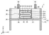
- FIG. 1A is an explanatory diagram in plan view of the sound generator according to the first embodiment.
- 1B is a cross-sectional view taken along line A-A ′ of FIG. 1A.
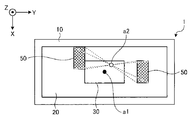
- FIG. 2 is an explanatory view in plan view for explaining the arrangement of the damping material.
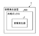
- FIG. 3 is a block diagram of the sound generator.
- FIG. 4 is a block diagram of the electronic device.
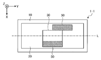
- FIG. 5A is an explanatory diagram in a plan view of an acoustic generator according to a first modification example of the first embodiment.
- FIG. 5B is an explanatory diagram in a plan view of an acoustic generator according to a second modification example of the first embodiment.
- FIG. 6 is an explanatory diagram in plan view of the sound generator according to the second embodiment.
- FIG. 5A is an explanatory diagram in plan view of an acoustic generator according to a first modification example of the first embodiment.
- FIG. 5B is an explanatory diagram in a plan view of
- FIG. 7 is an explanatory diagram in plan view of the sound generator according to the first modification of the second embodiment.
- FIG. 8A is an explanatory diagram in plan view of an acoustic generator according to a second modification of the second embodiment.
- FIG. 8B is an explanatory diagram in a plan view of an acoustic generator according to a third modification of the second embodiment.
- FIG. 8C is an explanatory diagram of the acoustic generator according to the fourth modification example of the second embodiment in plan view.
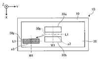
- FIG. 9 is an explanatory diagram in plan view of the sound generator according to the third embodiment.
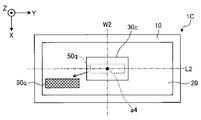
- FIG. 10 is an explanatory diagram in plan view of the sound generator according to the fourth embodiment.
- the sound generator 1 is a so-called piezoelectric speaker, and has a configuration for generating sound pressure using a resonance phenomenon of a vibrating body.
- the acoustic generator 1 includes a frame body 10, a vibrating body 20 stretched on the frame body 10, and a piezoelectric element provided on the vibrating body 20.
- the vibration element 30 and the damping material 50 are provided.
- FIG. 1A is an explanatory diagram in a plan view of the sound generator 1 according to the first embodiment viewed from a direction perpendicular to the main surface of the vibrating body 20, and FIG. 1B is an AA ′ diagram in FIG. 1A. It is line sectional drawing. In FIG. 1B, in order to facilitate understanding, the sound generator 1 is shown expanded and deformed in the vertical direction.
- the vibrating body 20 can be formed using various materials such as resin, metal, and paper.
- the thin plate-like vibrating body 20 can be made of a resin film made of polyethylene, polyimide, polypropylene, or the like having a thickness of 10 to 200 ⁇ m. Since the resin film is a material having a lower elastic modulus and mechanical Q value than a metal plate or the like, the vibration body 20 is made of a resin film, so that the vibration body 20 bends and vibrates with a large amplitude, thereby reducing the sound pressure. It is possible to reduce the difference between the resonance peak and the dip by widening the width of the resonance peak and reducing the height in the frequency characteristics. A composite of metal and resin may be used as the vibrating body 20.
- the frame body 10 plays a role of holding the vibrating body 20 and forming a fixed end of vibration.
- a frame body 10 is configured by vertically joining together an upper frame member 11 and a lower frame member 12 that are rectangular.
- the outer peripheral part of the vibrating body 20 which consists of a resin film is pinched
- the thickness and material of the upper frame member 11 and the lower frame member 12 constituting the frame body 10 are not particularly limited, but in the first embodiment, because of excellent mechanical strength and corrosion resistance,
- a stainless steel material having a thickness of 100 to 5000 ⁇ m is used.
- the piezoelectric vibration element 30 includes a laminated body 33, surface electrode layers 34 and 35 formed on the upper and lower surfaces of the laminated body 33, and an external surface formed on the side surface where the end face of the internal electrode layer 32 of the laminated body 33 is exposed. Electrodes 36 and 37 are provided. Lead terminals 38 and 39 are connected to the external electrodes 36 and 37.
- the laminated body 33 is formed by alternately laminating four piezoelectric layers 31a, 31b, 31c, 31d made of ceramics and three internal electrode layers 32.
- the piezoelectric vibration element 30 has a rectangular main surface on the upper surface side and the lower surface side, and the piezoelectric layers 31a and 31b and the piezoelectric layers 31c and 31d are polarized in different directions in the thickness direction, respectively.
- the piezoelectric layers 31b and 31c are polarized in the same direction.
- the piezoelectric vibration element 30 when a voltage is applied to the piezoelectric vibration element 30 via the lead terminals 38 and 39, for example, the lower surface side of the piezoelectric vibration element 30, in other words, the piezoelectric layers 31c and 31d on the vibration body 20 side contract, while the upper surface The piezoelectric layers 31a and 31b on the side are deformed so as to extend.
- the piezoelectric layers 31a and 31b on the upper surface side of the piezoelectric vibration element 30 and the piezoelectric layers 31c and 31d on the lower surface side exhibit opposite expansion and contraction behavior, and as a result, the piezoelectric vibration element 30 is bent by a bimorph type. By vibrating, a certain vibration can be given to the vibrating body 20 to generate a sound.
- the piezoelectric vibration element 30 is a bimorph-type laminated piezoelectric vibration element, and the piezoelectric vibration element 30 itself bends and vibrates alone. Therefore, the piezoelectric vibration element 30 is, for example, a soft vibration body 20 regardless of the material of the vibration body 20. However, strong vibrations can be generated, and a sufficient sound pressure can be obtained with a small number of piezoelectric vibration elements 30.
- piezoelectric layers 31a, 31b, 31c, 31d As a material constituting the piezoelectric layers 31a, 31b, 31c, 31d, conventionally used are lead-free piezoelectric materials such as lead zirconate titanate, Bi layered compounds, and tungsten bronze structure compounds. Piezoelectric ceramics can be used.
- the material of the internal electrode layer 32 is mainly composed of a metal, for example, silver and palladium.
- the internal electrode layer 32 may contain ceramic components constituting the piezoelectric layers 31a, 31b, 31c, and 31d, whereby the piezoelectric layers 31a, 31b, 31c, and 31d and the internal electrode layers 32 and 32 are included. , 32 can be obtained, and the piezoelectric vibration element 30 in which the stress due to the difference in thermal expansion is reduced can be obtained.
- the surface electrode layers 34 and 35 and the external electrodes 36 and 37 are mainly composed of metal such as silver. Moreover, you may contain a glass component. By containing the glass component, it is possible to obtain a strong adhesion between the piezoelectric layers 31a, 31b, 31c, 31d and the internal electrode layer 32 and the surface electrode layers 34, 35 or the external electrodes 36, 37. .
- the glass component content may be, for example, 20% by volume or less.
- the wiring connected to the lead terminals 38 and 39 in order to reduce the height of the piezoelectric vibration element 30, it is preferable to use flexible wiring in which a metal foil such as copper or aluminum is sandwiched between resin films.
- the acoustic generator 1 includes a resin coating layer 40 filled in the frame body 10 so as to embed the piezoelectric vibration element 30.
- the piezoelectric vibration element 30 can be protected from the external environment.
- the entire surface of the vibrating body 20 is covered with the covering layer 40, but it is not necessary to cover the entire surface. That is, the acoustic generator 1 only needs to cover the piezoelectric vibration element 30 and at least a part of the surface of the vibration body 20 on the side where the piezoelectric vibration element 30 is disposed with the coating layer 40.
- the damping material 50 is formed in a substantially rectangular parallelepiped shape, for example.
- two damping members 50 having the same shape are disposed on both the left and right sides (Y-axis negative direction side and Y-axis positive direction side) of the piezoelectric vibration element 30.
- each damping material 50 is integrated with the vibrating body 20, the piezoelectric vibrating element 30, and the coating layer 40 by being attached to the surface of the coating layer 40 via an adhesive 60.
- the region in the vibrating body 20 in which the damping material 50 is disposed receives vibration loss due to the damping material 50 through the coating layer 40, thereby suppressing the resonance phenomenon. It becomes. That is, since the difference between the resonance peak and the dip can be reduced and the frequency characteristic of the sound pressure can be flattened, a favorable frequency characteristic of the sound pressure can be obtained.
- the exciter (piezoelectric vibration element 30) and the damping material 50 have the contour of the other member with respect to the axis of symmetry or the center of gravity of the figure drawn by the contour of one of the members. It was determined that the symmetry axis or the center of gravity of the figure to be drawn was not matched.
- the other member is a damping material 50.
- the other member is an exciter (piezoelectric vibration element 30). It is.
- the plurality of damping materials 50 are arranged such that the composite vibration body constituted by the vibration body 20, the piezoelectric vibration element 30, the coating layer 40, and the damping material 50 is asymmetric as a whole.
- the degenerated vibration mode is dispersed into a plurality of vibration modes to generate a plurality of resonance peaks.
- FIG. 2 is an explanatory diagram in plan view for explaining the arrangement of the damping material 50.
- 1A, 1B and FIG. 2 illustrate two damping members 50, the number is not limited.
- the two damping members 50 describe the outline of the piezoelectric vibration element 30 when the vibrating body 20 is viewed in a plan view from a direction perpendicular to the main surface of the vibrating body 20 (Z-axis direction in the drawing). They are arranged so as to be asymmetric with respect to the symmetry axis of the figure. More specifically, the two damping materials 50 are arranged at a position where the rotational symmetry axis a2 of the two damping materials 50 does not coincide with the rotational symmetry axis a1 of the piezoelectric vibration element 30.
- the two damping members 50 are arranged in a non-rotational symmetry with respect to the rotational symmetry axis a1 of the piezoelectric vibration element 30.
- the composite vibration body constituted by the vibration body 20, the piezoelectric vibration element 30, the coating layer 40, and the damping material 50 becomes asymmetric as a whole.
- the degeneration of the vibration mode can be solved and dispersed in a plurality of vibration modes.
- the sound generator 1 it is possible to reduce the peak level of the resonance frequency and obtain a favorable sound pressure frequency characteristic with small fluctuation.
- the frequency characteristics of the sound pressure in the middle range can be made close to flat, good sound quality can be obtained.
- the two damping members 50 are both with respect to the other symmetry axes of the piezoelectric vibration element 30 (longitudinal line symmetry axis L shown in FIG. 5A and short line symmetry axis W shown in FIG. 5B). Are also arranged axisymmetrically with respect to each other. This also makes it possible to reduce the symmetry of the composite vibration body constituted by the vibration body 20, the piezoelectric vibration element 30, the coating layer 40, and the damping material 50.
- the position of the rotational symmetry axis a1 of the piezoelectric vibration element 30 is assumed to coincide with the center of gravity of the piezoelectric vibration element 30. That is, since the two damping materials 50 are arranged in a non-rotationally symmetrical manner with respect to the center of gravity of the piezoelectric vibration element 30, the vibration body 20, the piezoelectric vibration element 30, the coating layer 40, and the damping material are also arranged by this. The symmetry of the composite vibrator constituted by 50 can be lowered.
- the axis of symmetry of the piezoelectric vibration element 30 means the symmetry of the figure drawn by the outline of the piezoelectric vibration element 30 when the vibration body 20 is viewed in a plan view from a direction perpendicular to the main surface of the vibration body 20. It means the axis.
- the center of gravity of the piezoelectric vibration element 30 means the center of gravity (center) of a figure drawn by the outline of the piezoelectric vibration element 30 or the center of gravity (center of mass) of the piezoelectric vibration element 30 itself when viewed in plan.
- the two damping members 50 are arranged asymmetrically with respect to all three symmetry axes and the center of gravity of the piezoelectric vibration element 30 .
- the two damping members 50 may be asymmetric with respect to any of the three symmetry axes and the center of gravity of the piezoelectric vibration element 30.
- the two damping members 50 are arranged at positions that are non-rotationally symmetric with respect to the rotational symmetry axis a1 of the piezoelectric vibration element 30 but are symmetric with respect to the line symmetry axis L or the line symmetry axis W. Also good.
- the two damping members 50 are non-axisymmetric with respect to the line symmetry axis L or the line symmetry axis W of the piezoelectric vibration element 30, but may be arranged at positions that are rotationally symmetric with respect to the rotation symmetry axis a ⁇ b> 1. Good.
- the damping material 50 may be any member that has mechanical loss, but is preferably a member having a high mechanical loss factor, in other words, a low mechanical quality factor (so-called mechanical Q).
- a damping material 50 can be formed using various elastic bodies, for example, but since it is desirable that it is soft and easily deformed, it can be suitably formed using a rubber material such as urethane rubber. In particular, a porous rubber material such as urethane foam can be suitably used.
- the rotational symmetry axis a1 of the piezoelectric vibration element 30 and the center of gravity of the piezoelectric vibration element 30 coincide with each other is shown, but the rotation symmetry axis a1 of the piezoelectric vibration element 30 and the center of gravity of the piezoelectric vibration element 30 are It doesn't necessarily need to match. If these do not match, the plurality of damping members 50 may be disposed asymmetrically with respect to either the symmetry axis or the center of gravity of the piezoelectric vibration element 30.
- FIG. 3 is a block diagram of the sound generator.
- the acoustic generator 4 can be configured by housing the acoustic generator 1 having the above-described configuration in a resonance box 400.
- the resonance box 400 is a housing that houses the sound generator 1, and resonates the sound emitted from the sound generator 1 and radiates it as sound waves from the housing surface.
- Such a sound generator 4 can be used alone as a speaker, and can be suitably incorporated into various electronic devices 2, for example.
- the sound generator 1 can be used for a mobile phone or a thin television. Alternatively, it can be suitably incorporated into the electronic device 2 such as a tablet terminal.
- the electronic device 2 to which the sound generator 1 can be incorporated is not limited to the above-described mobile phone, flat-screen TV, tablet terminal, and the like, and for example, a refrigerator, a microwave oven, a vacuum cleaner, a washing machine, and the like. Conventionally, home appliances that have not been focused on sound quality are also included.
- FIG. 4 is a block diagram of the electronic device 2.
- the electronic device 2 includes the acoustic generator 1 described above, an electronic circuit connected to the acoustic generator 1, and a housing 200 that houses the acoustic generator 1 and the electronic circuit.
- the electronic device 2 includes an acoustic generator 1, an electronic circuit including a control circuit 21, a signal processing circuit 22, and a wireless circuit 23 as an input device, an antenna 24, and these And a housing 200 for storing the.
- the wireless input device is shown in FIG. 4, it can be provided as a signal input by normal electric wiring.
- the control circuit 21 controls the entire electronic device 2 including the wireless circuit 23 via the signal processing circuit 22.
- An output signal to the sound generator 1 is input from the signal processing circuit 22.
- the control circuit 21 generates a sound signal S by controlling the signal processing circuit 22 from the signal input to the radio circuit 23 and outputs the sound signal S to the sound generator 1.
- the electronic device 2 shown in FIG. 4 incorporates the small and thin acoustic generator 1 and reduces the difference between the resonance peak and the dip to suppress the frequency fluctuation as much as possible. It is possible to improve the sound quality as a whole even in a high sound region including a low sound region having a low sound level.
- the electronic device 2 in which the sound generator 1 is directly mounted is illustrated as the sound output device.
- the sound output device for example, a sound generator 4 in which the sound generator 1 is housed in a housing is mounted. It may be the configuration.
- the arrangement example of the damping material 50 that lowers the symmetry of the composite vibration body constituted by the vibration body 20, the piezoelectric vibration element 30, the coating layer 40, and the damping material 50 is not limited to the one shown in FIG. .
- Another arrangement example of the damping material 50 will be described with reference to FIGS. 5A and 5B.
- 5A and 5B are explanatory views of the sound generator according to the first and second modifications of the first embodiment in plan view.
- FIG. 5A shows the symmetry axis in the longitudinal direction of the piezoelectric vibration element 30 as the symmetry axis L
- FIG. 5B shows the symmetry axis in the short direction of the piezoelectric vibration element 30 as the symmetry axis W.
- the symmetry axis L and the symmetry axis W may be shown in other drawings used in the description below.
- the two damping members 50 are arranged at positions that are asymmetric with respect to the longitudinal symmetry axis L of the piezoelectric vibration element 30. Thereby, the symmetry of the composite vibrating body constituted by the vibrating body 20, the piezoelectric vibrating element 30, the coating layer 40, and the damping material 50 can be lowered.
- the two damping members 50 are arranged at positions that are asymmetric with respect to the symmetry axis W in the short direction of the piezoelectric vibration element 30. Thereby, the symmetry of the composite vibrating body constituted by the vibrating body 20, the piezoelectric vibrating element 30, the coating layer 40, and the damping material 50 can be lowered.
- FIG. 2 is an explanatory diagram in plan view of the sound generator according to the second embodiment.
- the sound generator 1 ⁇ / b> A according to the second embodiment is replaced with a damping material instead of one of the two damping materials 50 included in the sound generator 1 according to the first embodiment. 50a.
- the area of the damping material 50 a when the vibrating body 20 is viewed in plan is smaller than that of the damping material 50.
- FIG. 6 shows a case where two damping members 50 are arranged at positions that are rotationally symmetric with respect to the rotational symmetry axis a ⁇ b> 1 of the piezoelectric vibration element 30.
- one of the damping materials 50 in such an assumption is shown by the broken-line rectangle which abbreviate
- two damping members 50 are arranged symmetrically with respect to the rotational symmetry axis a1 of the piezoelectric vibration element 30.
- one of the damping members 50 indicated by a broken line is By making the damping material 50 a smaller in area in plan view than the other damping material 50, the symmetry of the composite vibration body constituted by the vibration body 20, the piezoelectric vibration element 30, the coating layer 40 and the damping material 50 is increased. Can be lowered.
- the symmetry of the composite vibrator can be lowered. Therefore, it is possible to obtain a sound generator having a good sound pressure frequency characteristic in which the vibration mode degeneration can be solved and dispersed, and the sound pressure fluctuation is small.
- the damping materials 50 and 50a having different areas are arranged at positions facing each other with the piezoelectric vibration element 30 interposed therebetween.
- the areas of the damping materials 50 and 50a facing each other across the piezoelectric vibration element 30 different from each other, for example, when the areas of the adjacent damping materials are made different, the symmetry of the composite vibrator is further reduced. can do.
- FIG. 6 shows an example in which the area of the damping material in plan view is different, but this is not limiting, and the shape of the damping material in plan view may be different. This point will be described with reference to FIG.
- FIG. 7 is an explanatory diagram in plan view of the sound generator according to the first modification of the second embodiment.
- one of the damping materials 50 indicated by the broken line is replaced with the other damping material 50 under the same assumptions as in FIG.
- the damping material 50b has a different planar shape. Thereby, the symmetry of the composite vibration body constituted by the vibration body 20, the piezoelectric vibration element 30, the coating layer 40, and the damping material 50 can be lowered.
- the planar shape of the at least one damping material 50b (the shape when seen in a plan view from the direction perpendicular to the main surface of the vibrating body 20) is different from the planar shape of the other damping materials 50, thereby combining The symmetry of the vibrating body can be lowered. Therefore, it is possible to obtain the sound generator 1A-1 having a good sound pressure frequency characteristic in which the vibration mode degeneration can be solved and dispersed, and the fluctuation of the sound pressure is small.
- FIGS. 8A to 8C are explanatory views in plan view of the acoustic generators according to second to fourth modifications of the second embodiment, respectively.
- 8A to 8C show an example in which four damping materials are arranged.
- the upper side X-axis negative direction side
- the lower side Two damping materials are arranged side by side on the X-axis positive direction side.
- the damping material 50d and the damping material 50e are arranged side by side on the upper side of the piezoelectric vibration element 30, and the damping material 50f and the damping material 50g are arranged on the lower side of the piezoelectric vibration element 30.
- the damping materials 50d and 50e have different areas when the vibrating body 20 is viewed in plan, and the damping materials 50f and 50g also have different areas when the vibrating body 20 is viewed in plan. .
- the composite The symmetry of the vibrating body can be lowered.
- the sound generator 1A-3 according to the third modification includes four damping materials 50h to 50k. These damping materials 50h to 50k have different areas in plan view. Thus, by making the areas of all the damping materials 50h to 50k different, the symmetry of the composite vibrator can be further reduced.
- the sound generator 1A-4 according to the third modification includes four damping materials 50l to 50o. These damping materials 50l to 50o are all different in shape in plan view. Thus, by making all the four damping members 50l to 50o different in shape, the symmetry of the composite vibrator can be further reduced.
- FIG. 9 is an explanatory diagram in plan view of the sound generator according to the third embodiment.
- the acoustic generator 1B according to the third embodiment differs from the above-described embodiments in that it includes one damping material 50p and a plurality of piezoelectric vibration elements (here, two Piezoelectric vibration elements 30a and 30b).
- the arrangement of the damping material 50p is assumed by broken lines so that the two piezoelectric vibration elements 30a and 30b are symmetrical with respect to the damping material 50p. That is, when the vibrating body 20 is viewed in plan, the symmetry axis of the figure drawn by the outline of the damping material 50p indicated by the broken line (rotation symmetry axis a3, longitudinal line symmetry axis L1, transverse direction line symmetry axis W1) The piezoelectric vibration elements 30a and 30b are arranged so as to be symmetric with respect to each other.
- the position of the rotational symmetry axis a3 of the damping material 50p is assumed to coincide with the center of gravity of the damping material 50p. Accordingly, the two piezoelectric vibration elements 30a and 30b are arranged in rotational symmetry with respect to the center of gravity of the damping material 50p indicated by a broken line.
- FIG. 10 is an explanatory diagram in plan view of the sound generator according to the fourth embodiment.
- the sound generator 1C includes one piezoelectric vibration element 30c and one damping material 50q.
- the arrangement of the damping material 50q that is symmetric with respect to the piezoelectric vibration element 30c is indicated by a broken line.
- the damping material 50q indicated by the broken line shows the symmetry axis (rotation symmetry axis a4, longitudinal line symmetry axis L2, longitudinal direction line symmetry axis W2) of the piezoelectric vibration element 30c when the vibrating body 20 is viewed in plan. ) With respect to each other.
- the damping material 50q indicated by the broken line is disposed rotationally symmetrically with respect to the center of gravity of the piezoelectric vibration element 30c.
- the damping material 50q is arranged symmetrically with respect to the symmetry axis or the center of gravity of the piezoelectric vibration element 30c.
- the damping material 50q is located from the position indicated by the broken line.
- the acoustic generator is provided with a plurality of piezoelectric vibration elements and a plurality of damping materials. May be. Further, although the piezoelectric vibration element is rectangular in plan view, the piezoelectric vibration element may be square.
- piezoelectric vibration element a so-called bimorph type laminated piezoelectric vibration element is illustrated, but a unimorph type piezoelectric vibration element can also be used.
- the exciter is not limited to a piezoelectric vibration element, and an electric signal is input. What has a function to vibrate is sufficient.
- an electrodynamic exciter, an electrostatic exciter, or an electromagnetic exciter well known as an exciter for vibrating a speaker may be used.
- the electrodynamic exciter is such that an electric current is passed through a coil disposed between the magnetic poles of a permanent magnet to vibrate the coil.
- the electrostatic exciter is composed of two metals facing each other. A bias and an electric signal are passed through the plate to vibrate the metal plate, and an electromagnetic exciter is an electric signal that is passed through the coil to vibrate a thin iron plate.
Landscapes
- Physics & Mathematics (AREA)
- Engineering & Computer Science (AREA)
- Acoustics & Sound (AREA)
- Signal Processing (AREA)
- Health & Medical Sciences (AREA)
- Otolaryngology (AREA)
- Piezo-Electric Transducers For Audible Bands (AREA)
Abstract
【課題】良好な音圧の周波数特性を得ること。 【解決手段】実施形態に係る音響発生器は、振動体と、励振器と、ダンピング材とを備える。励振器は、振動体上に設けられる。ダンピング材は、振動体と一体化するように取り付けられる。そして、振動体を平面視した場合に、励振器およびダンピング材のいずれか一方の部材の輪郭が描く図形の対称軸または重心に対して他方の部材の輪郭が描く図形の対称軸または重心が一致しないように他方が配置されている。
Description
開示の実施形態は、音響発生器、音響発生装置および電子機器に関する。
従来、アクチュエータを用いた音響発生器が知られている。たとえば、特許文献1には、振動板に取り付けた圧電素子に電圧を印加して振動させることによって、振動板を振動させて音響を出力する音響発生器が記載されている。
しかしながら、上記した従来の音響発生器は、振動板の共振を積極的に利用するが故に、音圧の周波数特性においてピーク(周囲よりも音圧が高い部分)およびディップ(周囲よりも音圧が低い部分)が生じやすく、良質な音質を得にくいという問題があった。
実施形態の一態様は、上記に鑑みてなされたものであって、良好な音圧の周波数特性を得ることができる音響発生器、音響発生装置および電子機器を提供することを目的とする。
実施形態の一態様に係る音響発生器は、振動体と、励振器と、ダンピング材とを備える。励振器は、振動体上に設けられる。ダンピング材は、振動体と一体化するように取り付けられる。そして、振動体を平面視した場合に、励振器およびダンピング材は、いずれか一方の部材の輪郭が描く図形の対称軸または重心に対して他方の部材の輪郭が描く図形の対称軸または重心が一致しないように配置されている。
実施形態の一態様によれば、良好な音圧の周波数特性を得ることができる。
以下、添付図面を参照して、本願の開示する音響発生器、音響発生装置および電子機器の実施形態について説明する。なお、以下に示す各実施形態によりこの発明が限定されるものではない。
(第1の実施形態)
第1の実施形態に係る音響発生器の構成について、図1Aおよび図1Bを用いて説明する。
(第1の実施形態)
第1の実施形態に係る音響発生器の構成について、図1Aおよび図1Bを用いて説明する。
第1の実施形態に係る音響発生器1は、いわゆる圧電スピーカと呼ばれるものであり、振動体の共振現象を用いて音圧を発生させる構成を備える。具体的には、音響発生器1は、図1Aおよび図1Bに示すように、枠体10と、この枠体10に張設された振動体20と、この振動体20上に設けられた圧電振動素子30と、ダンピング材50とを備える。
なお、図1Aは、第1の実施形態に係る音響発生器1を振動体20の主面に垂直な方向から見た平面視による説明図であり、図1Bは、図1AのA-A’線断面図である。図1Bにおいては、理解を容易にするために、音響発生器1を上下方向に拡張してデフォルメして示している。
振動体20は、樹脂、金属、紙などの種々の材料を用いて形成することができる。例えば、厚さ10~200μmのポリエチレン、ポリイミド、ポリプロピレンなどの樹脂フィルムにより薄板状の振動体20を構成することができる。樹脂フィルムは金属板などに比べて弾性率および機械的なQ値の低い材料であるため、振動体20を樹脂フィルムにより構成することで、振動体20を大きな振幅で屈曲振動させ、音圧の周波数特性における共振ピークの幅を広く、高さを低くして共振ピークとディップとの差を低減することができる。なお、金属と樹脂との複合体を振動体20として用いてもよい。
枠体10は、振動体20を保持して振動の固定端を形成する役割を担っている。たとえば、図1Bに示すように、共に矩形状の上枠部材11と下枠部材12とを、上下に接合して枠体10を構成している。そして、上枠部材11と下枠部材12との間に樹脂フィルムからなる振動体20の外周部を挟み込み、所定の張力を付与した状態で固定している。したがって、長期間使用してもたわみなどの変形の少ない振動体20を備えた音響発生器1となる。
枠体10を構成する上枠部材11と下枠部材12の厚みおよび材質は、特に限定されるものではないが、第1の実施形態では、機械的強度および耐食性に優れているという理由から、たとえば、厚さ100~5000μmのステンレス製の材料を用いている。
圧電振動素子30は、積層体33と、この積層体33の上面および下面に形成された表面電極層34、35と、積層体33の内部電極層32の端面が露出する側面に形成された外部電極36、37とを備えている。そして、外部電極36、37にリード端子38、39が接続されている。
積層体33は、セラミックスからなる4層の圧電体層31a、31b、31c、31dと、3層の内部電極層32とが交互に積層されて形成される。また、圧電振動素子30は、上面側および下面側の主面を矩形状としており、圧電体層31aと31b、圧電体層31cと31dは、それぞれ厚み方向に互いに異なる向きに分極されており、圧電体層31bと31cは同じ向きに分極されている。
したがって、リード端子38、39を介して圧電振動素子30に電圧が印加された場合、例えば圧電振動素子30の下面側、換言すれば振動体20側の圧電体層31c、31dは縮む一方、上面側の圧電体層31a、31bは伸びるように変形する。このように、圧電振動素子30の上面側の圧電体層31a、31bと下面側の圧電体層31c、31dとが、相反する伸縮挙動を示し、その結果、圧電振動素子30がバイモルフ型の屈曲振動をすることにより、振動体20に一定の振動を与えて音を発生させることができる。
このように、圧電振動素子30がバイモルフ型の積層型圧電振動素子であり、圧電振動素子30自体が単独で屈曲振動することから、振動体20の材質によらず、例えば柔らかい振動体20であっても強い振動を発生させることができ、少数の圧電振動素子30により充分な音圧を得ることができる。
ここで、圧電体層31a、31b、31c、31dを構成する材料としては、チタン酸ジルコン酸鉛、Bi層状化合物、タングステンブロンズ構造化合物などの非鉛系圧電体材料などの、従来から用いられている圧電セラミックスを用いることができる。
また、内部電極層32の材料は、金属、例えば銀とパラジウムを主成分とする。なお、内部電極層32には圧電体層31a、31b、31c、31dを構成するセラミック成分を含有しても良く、これにより、圧電体層31a、31b、31c、31dと内部電極層32、32、32との熱膨張差による応力を低減した圧電振動素子30を得ることができる。
また、表面電極層34、35と外部電極36、37は、金属、例えば銀などを主成分とする。また、ガラス成分を含有しても良い。ガラス成分を含有させることによって、圧電体層31a、31b、31c、31dや内部電極層32と、表面電極層34、35または外部電極36、37との間に強固な密着力を得ることができる。ガラス成分の含有量は、たとえば20体積%以下とすればよい。
また、リード端子38、39に接続する配線としては、圧電振動素子30の低背化を図るために、銅またはアルミニウムなどの金属箔を樹脂フィルムで挟んだフレキシブル配線を用いるのが好ましい。
また、第1の実施形態に係る音響発生器1は、図1Bに示すように、圧電振動素子30を埋設するように、枠体10内に充填された樹脂製の被覆層40を備える。このように、圧電振動素子30を樹脂製の被覆層40で埋設することにより、適度なダンピング効果を誘発させることができ、共振現象を抑制するとともに、共振ピークとディップとの差をより小さく抑えることができる。さらに、圧電振動素子30を外部環境から保護することもできる。
なお、第1の実施形態では、振動体20の表面全てが被覆層40により被覆されているが、全てが被覆される必要はない。すなわち、音響発生器1は、圧電振動素子30と、この圧電振動素子30が配置されている側の振動体20の表面の少なくとも一部とが被覆層40により被覆されていればよい。
ダンピング材50は、例えば略直方体形状に形成される。第1の実施形態では、同一の形状を有する2個のダンピング材50が、圧電振動素子30の左右両側(Y軸負方向側およびY軸正方向側)にそれぞれ配置される。また、各ダンピング材50は、図1Bに示すように、被覆層40の表面に接着剤60を介して取り付けられることによって、振動体20、圧電振動素子30および被覆層40と一体化される。
このように、ダンピング材50を設けることによって、ダンピング材50が配置された振動体20における領域は、被覆層40を介してダンピング材50による振動損失を受け、これにより共振現象が抑制されることとなる。すなわち、共振ピークとディップとの差を低減させ、音圧の周波数特性を平坦化することができるため、良好な音圧の周波数特性を得ることができる。
さらに、振動体20を平面視した場合に、励振器(圧電振動素子30)およびダンピング材50は、いずれか一方の部材の輪郭が描く図形の対称軸または重心に対して他方の部材の輪郭が描く図形の対称軸または重心が一致しないように配置されていることとした。ここで、一方の部材が励振器(圧電振動素子30)の場合、他方の部材はダンピング材50であり、一方の部材がダンピング材50の場合、他方の部材は励振器(圧電振動素子30)である。
例えば、第1の実施形態では、複数のダンピング材50を、振動体20、圧電振動素子30、被覆層40およびダンピング材50によって構成される複合振動体が全体として非対称となるように配置することによって、縮退した振動モードを複数の振動モードに分散させ、複数の共振ピークを発生させることとした。
この点について、図2を用いて具体的に説明する。図2は、ダンピング材50の配置を説明するための平面視による説明図である。なお、図1A、1Bおよび図2には、2個のダンピング材50を例示しているが、その個数を限定するものではない。
図2に示すように、2個のダンピング材50は、振動体20を振動体20の主面に垂直な方向(図のZ軸方向)から平面視した場合に圧電振動素子30の輪郭が描く図形の対称軸に対して互いに非対称となるように配置される。より具体的には、2個のダンピング材50の回転対称軸a2が圧電振動素子30の回転対称軸a1と一致しない位置に、これら2個のダンピング材50を配置する。
これにより、2個のダンピング材50は、圧電振動素子30の回転対称軸a1に対して互いに非回転対称に配置される。この結果、振動体20、圧電振動素子30、被覆層40およびダンピング材50によって構成される複合振動体が全体として非対称となる。これにより、振動モードの縮退を解いて複数の振動モードに分散させることができる。
したがって、第1の実施形態に係る音響発生器1によれば、共振周波数のピークのレベルを小さくして、変動の小さい、良好な音圧の周波数特性を得ることができる。とりわけ、中音域の音圧の周波数特性をフラットに近づけることができるので、良好な音質を得ることができる。
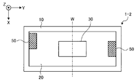
また、2個のダンピング材50は、圧電振動素子30の他の対称軸(図5Aに示す長手方向の線対称軸Lおよび図5Bに示す短手方向の線対称軸W)の両方に対しても互いに非線対称に配置される。これによっても、振動体20、圧電振動素子30、被覆層40およびダンピング材50によって構成される複合振動体の対称性を低くすることができる。
また、第1の実施形態において、圧電振動素子30の回転対称軸a1の位置は、圧電振動素子30の重心と一致するものとする。すなわち、2個のダンピング材50は、圧電振動素子30の重心に対しても互いに非回転対称に配置されているため、これによっても、振動体20、圧電振動素子30、被覆層40およびダンピング材50によって構成される複合振動体の対称性を低くすることができる。
なお、本明細書において、「圧電振動素子30の対称軸」とは、振動体20を振動体20の主面に垂直な方向から平面視した場合に圧電振動素子30の輪郭が描く図形の対称軸のことを意味する。また、「圧電振動素子30の重心」とは、平面視した場合に圧電振動素子30の輪郭が描く図形の重心(中心)もしくは圧電振動素子30そのものの重心(質量中心)を意味する。
このように、複数のダンピング材50を、圧電振動素子30の対称軸または重心に対して非対称に配置することにより、良好な音圧を得ることができる。
なお、ここでは、2個のダンピング材50が、圧電振動素子30の3つの対称軸および重心のすべてに対して非対称に配置される場合の例を示した。しかし、2個のダンピング材50は、圧電振動素子30の3つの対称軸および重心のうちのいずれかに対して非対称であればよい。たとえば、2個のダンピング材50は、圧電振動素子30の回転対称軸a1に対して非回転対称であるが線対称軸Lまたは線対称軸Wに対しては線対称となる位置に配置されてもよい。また、2個のダンピング材50は、圧電振動素子30の線対称軸Lまたは線対称軸Wに対して非線対称であるが回転対称軸a1に対して回転対称となる位置に配置されてもよい。
ダンピング材50は、機械的損失を有するものであればよいが、機械的損失係数が高い、言い換えれば、機械的品質係数(いわゆる、メカニカルQ)が低い部材であることが望ましい。このようなダンピング材50は、たとえば、種々の弾性体を用いて形成することができるが、柔らかく変形しやすいことが望ましいため、ウレタンゴム等のゴム材料を用いて好適に形成することができる。特に、ウレタンフォーム等の多孔質なゴム材料を好適に用いることができる。
ここでは、圧電振動素子30の回転対称軸a1と圧電振動素子30の重心とが一致する場合の例を示したが、圧電振動素子30の回転対称軸a1と圧電振動素子30の重心とは、必ずしも一致することを要しない。これらが一致しない場合、複数のダンピング材50は、圧電振動素子30の対称軸または重心のいずれかに対して非対称に配置されればよい。
次に、本実施形態に係る音響発生器1を搭載した音響発生装置について図3を参照して説明する。図3は、音響発生装置のブロック図である。
図3に示すように、上述してきた構成の音響発生器1を、共鳴ボックス400に収納することにより音響発生装置4を構成することができる。共鳴ボックス400は、音響発生器1を収納する筐体であり、音響発生器1の発する音響を共鳴させて筐体面から音波として放射する。かかる音響発生装置4は、スピーカとして単独で用いることができる他、例えば、各種電子機器2へ好適に組み込むことが可能である。
上述してきたように、圧電スピーカでは不利であった音圧の周波数特性における共振ピークとディップとの差を低減させることができるため、本実施形態に係る音響発生器1は、携帯電話機や薄型テレビ、あるいはタブレット端末などの電子機器2へ好適に組み込むことが可能である。
なお、音響発生器1が組み込まれる対象となりうる電子機器2としては、前述の携帯電話機や薄型テレビ、あるいはタブレット端末などに限らず、たとえば、冷蔵庫、電子レンジ、掃除機、洗濯機などのように、従来、音質については重視されなかった家電製品も含まれる。
ここで、上述した音響発生器1を備える電子機器2について、図4を参照しながら簡単に説明する。図4は、電子機器2のブロック図である。電子機器2は、上述してきた音響発生器1と、音響発生器1に接続された電子回路と、音響発生器1および電子回路を収納する筐体200とを備えている。
具体的には、図4に示すように、電子機器2は、音響発生器1と、制御回路21、信号処理回路22および入力装置としての無線回路23を含む電子回路と、アンテナ24と、これらを収納する筐体200とを備えている。なお、無線による入力装置を図4に図示しているが、通常の電気配線による信号入力としても当然設けることができる。
なお、ここでは、電子機器2が備える他の電子部材(たとえば、ディスプレイ、マイク、スピーカなどのデバイスや回路)については記載を省略した。また、図4では、1つの音響発生器1を例示したが、2つ以上の音響発生器1やその他の発振器を設けることもできる。
制御回路21は、信号処理回路22を介して無線回路23を含む電子機器2全体を制御する。音響発生器1への出力信号は、信号処理回路22から入力される。そして、制御回路21は、無線回路23へ入力された信号を、信号処理回路22を制御することによって音声信号Sを生成し、音響発生器1に対して出力する。
このようにして、図4に示す電子機器2は、小型かつ薄型である音響発生器1を組み込みながらも、共振ピークとディップとの差を低減して周波数変動を可及的に抑制し、周波数の低い低音領域をはじめ、高音領域においても全体的に音質の向上を図ることができる。
なお、図4においては、音響出力デバイスとして音響発生器1を直接搭載した電子機器2を例示したが、音響出力デバイスとしては、たとえば音響発生器1を筐体に収納した音響発生装置4を搭載した構成であってもよい。
ところで、振動体20、圧電振動素子30、被覆層40およびダンピング材50によって構成される複合振動体の対称性を低くするようなダンピング材50の配置例は、図2に示したものに限定されない。こうしたダンピング材50の他の配置例について、図5Aおよび図5Bを参照して説明する。図5Aおよび図5Bは、第1の実施形態における第1および第2の変形例に係る音響発生器の平面視による説明図である。
なお、図5Aには、圧電振動素子30の長手方向の対称軸を対称軸Lとして、図5Bには、圧電振動素子30の短手方向の対称軸を対称軸Wとして、それぞれ示している。かかる対称軸Lおよび対称軸Wは、後述の説明に用いる他の図面でも示す場合がある。
図5Aに示す音響発生器1-1では、2個のダンピング材50が、圧電振動素子30の長手方向の対称軸Lに対して非対称となる位置に配置される。これにより、振動体20、圧電振動素子30、被覆層40およびダンピング材50によって構成される複合振動体の対称性を低くすることができる。
また、図5Bに示す音響発生器1-2では、2個のダンピング材50が、圧電振動素子30の短手方向の対称軸Wに対して非対称となる位置に配置される。これにより、振動体20、圧電振動素子30、被覆層40およびダンピング材50によって構成される複合振動体の対称性を低くすることができる。
なお、図2、図5Aおよび図5Bに示した例は、圧電振動素子30が有する3つの対称軸のいずれに対しても非対称になるように、さらに、圧電振動素子30の重心に対しても非対称となるように複数のダンピング材50を配置するものである。このように、圧電振動素子30の全ての対称軸および重心に対して複数のダンピング材50を非対称に配置することにより、上記複合振動体の対称性をより一層低くすることができる。ただし、複数のダンピング材50は、圧電振動素子30が有する対称軸および重心のうち少なくとも1つに対して非対称であればよい。
(第2の実施形態)
次に、第2の実施形態に係る音響発生器の構成について図6を参照して説明する。図6は、第2の実施形態に係る音響発生器の平面視による説明図である。
(第2の実施形態)
次に、第2の実施形態に係る音響発生器の構成について図6を参照して説明する。図6は、第2の実施形態に係る音響発生器の平面視による説明図である。
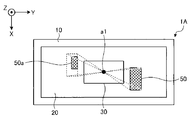
図6に示すように、第2の実施形態に係る音響発生器1Aは、第1の実施形態に係る音響発生器1が備える2個のダンピング材50のうちの1個に代えて、ダンピング材50aを備える。ダンピング材50aは、振動体20を平面視した場合の面積がダンピング材50よりも小さい。
図6では、2個のダンピング材50が、圧電振動素子30の回転対称軸a1について回転対称となる位置に配置された場合を仮定して示している。なお、かかる仮定におけるダンピング材50の一方を、図6では、符号を略した破線の矩形で示している。
かかる仮定のもとにおいては、圧電振動素子30の回転対称軸a1に対して対称に2個のダンピング材50が配置されることとなるが、たとえば、破線で示したダンピング材50の一方を、平面視した場合の面積が他方のダンピング材50よりも小さいダンピング材50aとすることによって、振動体20、圧電振動素子30、被覆層40およびダンピング材50によって構成される複合振動体の対称性を低くすることができる。
このように、少なくとも1つのダンピング材の平面視における面積を他のダンピング材の平面視における面積と異ならせることにより、複合振動体の対称性を低くすることができる。したがって、振動モードの縮退を解いて分散させることができ、音圧の変動が小さい良好な音圧の周波数特性を有する音響発生器を得ることができる。
また、第2の実施形態に係る音響発生器1Aでは、面積が互いに異なるダンピング材50、50aが、圧電振動素子30を挟んで対向する位置に配置される。このように、圧電振動素子30を挟んで向かい合うダンピング材50、50aの面積を異ならせることにより、たとえば隣り合うダンピング材の面積を異ならせる場合と比較して、複合振動体の対称性をさらに低くすることができる。
さらに、図6に示すように、面積が互いに異なるダンピング材を振動体20の長手方向に配置することで、短手方向に配置した場合と比較して、複合振動体の対称性をより効果的に低くすることができる。
図6では、ダンピング材の平面視における面積を異ならせる場合の例を示したが、これに限らず、ダンピング材の平面視における形状を異ならせてもよい。かかる点について図7を参照して説明する。図7は、第2の実施形態の第1の変形例に係る音響発生器の平面視による説明図である。
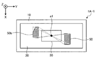
図7に示すように、第1の変形例に係る音響発生器1A-1では、図6と同様の仮定のもとで、破線で示したダンピング材50の一方を、他方のダンピング材50と平面形状の異なるダンピング材50bとしている。これによって、振動体20、圧電振動素子30、被覆層40およびダンピング材50によって構成される複合振動体の対称性を低くすることができる。
このように、少なくとも1つのダンピング材50bの平面形状(振動体20の主面に垂直な方向から平面視したときの形状)が他のダンピング材50の平面形状と異なるようにすることにより、複合振動体の対称性を低くすることができる。したがって、振動モードの縮退を解いて分散させることができ、音圧の変動が小さい良好な音圧の周波数特性を有する音響発生器1A-1を得ることができる。
次に、第2の実施形態に係る音響発生器1Aのさらなる変形例について図8A~図8Cを参照して説明する。図8A~図8Cは、それぞれ第2の実施形態の第2~第4の変形例に係る音響発生器の平面視による説明図である。図8A~図8Cには、4個のダンピング材が配置される場合の例を示している。
図8Aに示すように、第2の変形例に係る音響発生器1A-2では、振動体20を平面視した場合に、圧電振動素子30の上辺側(X軸負方向側)および下辺側(X軸正方向側)にダンピング材がそれぞれ2個ずつ並べて配置される。具体的には、圧電振動素子30の上辺側には、ダンピング材50dおよびダンピング材50eが並べて配置され、圧電振動素子30の下辺側には、ダンピング材50fおよびダンピング材50gが並べて配置される。
そして、図8Aに示すように、ダンピング材50d、50eは、振動体20を平面視した場合の面積がそれぞれ異なり、ダンピング材50f、50gも、振動体20を平面視した場合の面積がそれぞれ異なる。
このように、面積が互いに異なるダンピング材を、圧電振動素子30の一方側に並べて配置することにより、面積の等しいダンピング材を圧電振動素子30の一方側に並べて配置した場合と比較して、複合振動体の対称性を低くすることができる。
また、図8Bに示すように、第3の変形例に係る音響発生器1A-3は、4個のダンピング材50h~50kを備える。これらダンピング材50h~50kは、平面視における面積が全て異なっている。このように、全てのダンピング材50h~50kの面積を異ならせることにより、複合振動体の対称性をさらに低くすることができる。
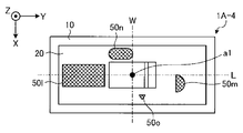
また、図8Cに示すように、第3の変形例に係る音響発生器1A-4は、4個のダンピング材50l~50oを備える。これらダンピング材50l~50oは、平面視における形状がすべて異なっている。このように、4個のダンピング材50l~50oの形状を全て異ならせることにより、複合振動体の対称性をさらに低くすることができる。
(第3の実施形態)
次に、第3の実施形態に係る音響発生器について図9を参照して説明する。図9は、第3の実施形態に係る音響発生器の平面視による説明図である。
(第3の実施形態)
次に、第3の実施形態に係る音響発生器について図9を参照して説明する。図9は、第3の実施形態に係る音響発生器の平面視による説明図である。
図9に示すように、第3の実施形態に係る音響発生器1Bは、上述してきた各実施形態とは異なり、1個のダンピング材50pと、複数の圧電振動素子(ここでは、2個の圧電振動素子30a、30b)とを備える。
ここで、図9では、2個の圧電振動素子30a、30bがダンピング材50pに対して対称となるようなダンピング材50pの配置を破線で仮定している。すなわち、振動体20を平面視した場合に、破線で示したダンピング材50pの輪郭が描く図形の対称軸(回転対称軸a3、長手方向の線対称軸L1、短手方向の線対称軸W1)に対して対称となるように、各圧電振動素子30a、30bが配置されている。
また、第3の実施形態において、ダンピング材50pの回転対称軸a3の位置は、ダンピング材50pの重心と一致するものとする。したがって、2個の圧電振動素子30a、30bは、破線で示したダンピング材50pの重心に対しても互いに回転対称に配置されていることとなる。
このように、かかる仮定のもとにおいては、ダンピング材50pの対称軸または重心に対して対称に2個の圧電振動素子30a、30bが配置されることとなるが、たとえば、ダンピング材50pを破線で示した位置からずらすことによって、振動体20、圧電振動素子30a、30b、被覆層40およびダンピング材50pによって構成される複合振動体の対称性を低くすることができる。
(第4の実施形態)
次に、第4の実施形態に係る音響発生器について図10を参照して説明する。図10は、第4の実施形態に係る音響発生器の平面視による説明図である。
(第4の実施形態)
次に、第4の実施形態に係る音響発生器について図10を参照して説明する。図10は、第4の実施形態に係る音響発生器の平面視による説明図である。
図10に示すように、第4の実施形態に係る音響発生器1Cは、圧電振動素子30cおよびダンピング材50qをそれぞれ1個ずつ備えている。
ここで、図10では、圧電振動素子30cに対して対称となるダンピング材50qの配置を破線で示している。すなわち、破線で示したダンピング材50qは、振動体20を平面視した場合に、圧電振動素子30cの対称軸(回転対称軸a4、長手方向の線対称軸L2、短手方向の線対称軸W2)に対して対称となる位置に配置されている。
また、第4の実施形態において、圧電振動素子30cの回転対称軸a4の位置は、圧電振動素子30cの重心と一致するものとする。したがって、破線で示したダンピング材50qは、圧電振動素子30cの重心に対しても回転対称に配置されていることとなる。
このように、かかる仮定のもとにおいては、圧電振動素子30cの対称軸または重心に対して対称にダンピング材50qが配置されることとなるが、たとえば、ダンピング材50qを破線で示した位置からずらすことによって、振動体20、圧電振動素子30c、被覆層40およびダンピング材50qによって構成される複合振動体の対称性を低くすることができる。
なお、上述してきた各実施形態では、圧電振動素子およびダンピング材のいずれかが単数である場合の例を示したが、音響発生器には、複数の圧電振動素子および複数のダンピング材が設けられてもよい。また、圧電振動素子を平面視で矩形状としたが、圧電振動素子は正方形であってもよい。
また、圧電振動素子として、いわゆるバイモルフ型の積層型圧電振動素子を例示したが、ユニモルフ型の圧電振動素子を用いることもできる。
また、上述した各実施形態では、励振器の一例として圧電振動素子を用いる場合を例に挙げて説明したが、励振器は、圧電振動素子に限定されるものではなく、電気信号が入力されて振動する機能を有しているものであれば良い。例えば、スピーカを振動させる励振器としてよく知られた、動電型の励振器や、静電型の励振器や、電磁型の励振器であっても構わない。なお、動電型の励振器は、永久磁石の磁極の間に配置されたコイルに電流を流してコイルを振動させるようなものであり、静電型の励振器は、向き合わせた2つの金属板にバイアスと電気信号とを流して金属板を振動させるようなものであり、電磁型の励振器は、電気信号をコイルに流して薄い鉄板を振動させるようなものである。
さらなる効果や変形例は、当業者によって容易に導き出すことができる。このため、本発明のより広範な態様は、以上のように表しかつ記述した特定の詳細および代表的な実施形態に限定されるものではない。したがって、添付の特許請求の範囲およびその均等物によって定義される総括的な発明の概念の精神または範囲から逸脱することなく、様々な変更が可能である。
1 音響発生器
2 電子機器
4 音響発生装置
10 枠体
20 振動体
30 圧電振動素子
40 被覆層
50 ダンピング材
60 接着剤
2 電子機器
4 音響発生装置
10 枠体
20 振動体
30 圧電振動素子
40 被覆層
50 ダンピング材
60 接着剤
Claims (12)
- 振動体と、
該振動体上に設けられた励振器と、
前記振動体と一体化するように取り付けられたダンピング材とを備え、
前記振動体を平面視した場合に、前記励振器および前記ダンピング材は、いずれか一方の部材の輪郭が描く図形の対称軸または重心に対して他方の部材の輪郭が描く図形の対称軸または重心が一致しないように配置されていることを特徴とする音響発生器。 - 前記励振器および前記ダンピング材のいずれか一方の部材が1個、他方の部材が複数設けられており、前記一方の部材の輪郭が描く図形の対称軸または重心に対して、複数の他方の部材が互いに非対称に配置されていることを特徴とする請求項1に記載の音響発生器。
- 前記一方の部材が前記励振器であり、複数の前記他方の部材が前記ダンピング材であり、前記励振器の輪郭が描く図形の対称軸または重心に対して、複数の前記ダンピング材が互いに非回転対称または非線対称に配置されていることを特徴とする請求項2に記載の音響発生器。
- 前記一方の部材が前記ダンピング材であり、複数の前記他方の部材が前記励振器であり、前記ダンピング材の輪郭が描く図形の対称軸または重心に対して、複数の前記励振器が互いに非回転対称または非線対称に配置されていることを特徴とする請求項2に記載の音響発生器。
- 複数の前記他方の部材の少なくとも一つは、前記振動体を平面視した場合の面積が他の前記他方の部材と異なることを特徴とする請求項2~4のいずれか一つに記載の音響発生器。
- 前記面積が互いに異なる複数の前記他方の部材が、前記一方の部材を挟んで対向する位置に配置されていることを特徴とする請求項5に記載の音響発生器。
- 前記面積が互いに異なる複数の前記他方の部材が、前記一方の部材の一方側に並べて配置されていることを特徴とする請求項5または6に記載の音響発生器。
- 複数の前記他方の部材の少なくとも一つは、前記振動体を平面視した場合の形状が他の前記他方の部材と異なることを特徴とする請求項5~7のいずれか一つに記載の音響発生器。
- 全ての前記他方の部材の前記面積が異なることを特徴とする請求項5~8のいずれか一つに記載の音響発生器。
- 前記励振器は、バイモルフ型の積層型圧電振動素子であることを特徴とする請求項1~9のいずれか一つに記載の音響発生器。
- 請求項1~10のいずれか一つに記載の音響発生器と、
該音響発生器を収容する筐体と
を備えることを特徴とする音響発生装置。 - 請求項1~10のいずれか一つに記載の音響発生器と、
該音響発生器に接続された電子回路と、
該電子回路および前記音響発生器を収容する筐体とを備え、
前記音響発生器から音響を発生させる機能を有することを特徴とする電子機器。
Applications Claiming Priority (2)
| Application Number | Priority Date | Filing Date | Title |
|---|---|---|---|
| JP2012-269650 | 2012-12-10 | ||
| JP2012269650 | 2012-12-10 |
Publications (1)
| Publication Number | Publication Date |
|---|---|
| WO2014091833A1 true WO2014091833A1 (ja) | 2014-06-19 |
Family
ID=50934131
Family Applications (1)
| Application Number | Title | Priority Date | Filing Date |
|---|---|---|---|
| PCT/JP2013/079530 Ceased WO2014091833A1 (ja) | 2012-12-10 | 2013-10-31 | 音響発生器、音響発生装置および電子機器 |
Country Status (1)
| Country | Link |
|---|---|
| WO (1) | WO2014091833A1 (ja) |
Citations (2)
| Publication number | Priority date | Publication date | Assignee | Title |
|---|---|---|---|---|
| WO2007052835A1 (ja) * | 2005-11-02 | 2007-05-10 | Nec Corporation | スピーカ、画像素子保護スクリーン、端末装置の筐体、および端末装置 |
| JP2010199818A (ja) * | 2009-02-24 | 2010-09-09 | Panasonic Corp | 平板スピーカ |
-
2013
- 2013-10-31 WO PCT/JP2013/079530 patent/WO2014091833A1/ja not_active Ceased
Patent Citations (2)
| Publication number | Priority date | Publication date | Assignee | Title |
|---|---|---|---|---|
| WO2007052835A1 (ja) * | 2005-11-02 | 2007-05-10 | Nec Corporation | スピーカ、画像素子保護スクリーン、端末装置の筐体、および端末装置 |
| JP2010199818A (ja) * | 2009-02-24 | 2010-09-09 | Panasonic Corp | 平板スピーカ |
Similar Documents
| Publication | Publication Date | Title |
|---|---|---|
| JP6047575B2 (ja) | 音響発生器、音響発生装置および電子機器 | |
| US9161134B2 (en) | Acoustic generator, acoustic generating device, and electronic device | |
| JP5908994B2 (ja) | 音響発生器、音響発生装置および電子機器 | |
| JP6053794B2 (ja) | 音響発生器、音響発生装置および電子機器 | |
| JP5638169B2 (ja) | 音響発生器、音響発生装置および電子機器 | |
| WO2014045720A1 (ja) | 音響発生器、音響発生装置及び電子機器 | |
| JP5602978B2 (ja) | 音響発生器、音響発生装置および電子機器 | |
| JP6192743B2 (ja) | 音響発生器,音響発生装置,電子機器 | |
| JP6166038B2 (ja) | 音響発生器、音響発生装置および電子機器 | |
| JP2014127767A (ja) | 音響発生器、音響発生装置および電子機器 | |
| JP5909169B2 (ja) | 音響発生器、音響発生装置および電子機器 | |
| JP2014123900A (ja) | 音響発生器、音響発生装置および電子機器 | |
| JP6034182B2 (ja) | 音響発生器、音響発生装置および電子機器 | |
| JP2014123812A (ja) | 音響発生器、音響発生装置および電子機器 | |
| JP5714190B2 (ja) | 音響発生器、音響発生装置および電子機器 | |
| WO2014091833A1 (ja) | 音響発生器、音響発生装置および電子機器 | |
| WO2014104018A1 (ja) | 音響発生器、音響発生装置および電子機器 | |
| JP6092618B2 (ja) | 音響発生器、音響発生装置および電子機器 | |
| JP2014072711A (ja) | 音響発生器、音響発生装置および電子機器 | |
| JP2014064212A (ja) | 音響発生器、音響発生装置及び電子機器 | |
| JP2014116795A (ja) | 音響発生器、音響発生装置および電子機器 | |
| WO2014091813A1 (ja) | 音響発生器、音響発生装置および電子機器 | |
| JP2015154298A (ja) | 音響発生器,音響発生装置,電子機器 |
Legal Events
| Date | Code | Title | Description |
|---|---|---|---|
| 121 | Ep: the epo has been informed by wipo that ep was designated in this application |
Ref document number: 13863051 Country of ref document: EP Kind code of ref document: A1 |
|
| NENP | Non-entry into the national phase |
Ref country code: DE |
|
| 122 | Ep: pct application non-entry in european phase |
Ref document number: 13863051 Country of ref document: EP Kind code of ref document: A1 |
|
| NENP | Non-entry into the national phase |
Ref country code: JP |