WO2014091700A1 - 充放電制御方法、充放電制御システムおよび充放電制御装置 - Google Patents
充放電制御方法、充放電制御システムおよび充放電制御装置 Download PDFInfo
- Publication number
- WO2014091700A1 WO2014091700A1 PCT/JP2013/006995 JP2013006995W WO2014091700A1 WO 2014091700 A1 WO2014091700 A1 WO 2014091700A1 JP 2013006995 W JP2013006995 W JP 2013006995W WO 2014091700 A1 WO2014091700 A1 WO 2014091700A1
- Authority
- WO
- WIPO (PCT)
- Prior art keywords
- power
- value
- power storage
- command value
- storage device
- Prior art date
Links
Images

Classifications
-
- H—ELECTRICITY
- H02—GENERATION; CONVERSION OR DISTRIBUTION OF ELECTRIC POWER
- H02J—CIRCUIT ARRANGEMENTS OR SYSTEMS FOR SUPPLYING OR DISTRIBUTING ELECTRIC POWER; SYSTEMS FOR STORING ELECTRIC ENERGY
- H02J7/00—Circuit arrangements for charging or depolarising batteries or for supplying loads from batteries
- H02J7/02—Circuit arrangements for charging or depolarising batteries or for supplying loads from batteries for charging batteries from ac mains by converters
- H02J7/04—Regulation of charging current or voltage
-
- H—ELECTRICITY
- H02—GENERATION; CONVERSION OR DISTRIBUTION OF ELECTRIC POWER
- H02J—CIRCUIT ARRANGEMENTS OR SYSTEMS FOR SUPPLYING OR DISTRIBUTING ELECTRIC POWER; SYSTEMS FOR STORING ELECTRIC ENERGY
- H02J3/00—Circuit arrangements for ac mains or ac distribution networks
- H02J3/28—Arrangements for balancing of the load in a network by storage of energy
- H02J3/32—Arrangements for balancing of the load in a network by storage of energy using batteries with converting means
-
- H—ELECTRICITY
- H02—GENERATION; CONVERSION OR DISTRIBUTION OF ELECTRIC POWER
- H02J—CIRCUIT ARRANGEMENTS OR SYSTEMS FOR SUPPLYING OR DISTRIBUTING ELECTRIC POWER; SYSTEMS FOR STORING ELECTRIC ENERGY
- H02J7/00—Circuit arrangements for charging or depolarising batteries or for supplying loads from batteries
- H02J7/007—Regulation of charging or discharging current or voltage
- H02J7/00712—Regulation of charging or discharging current or voltage the cycle being controlled or terminated in response to electric parameters
- H02J7/007182—Regulation of charging or discharging current or voltage the cycle being controlled or terminated in response to electric parameters in response to battery voltage
Definitions
- the present invention relates to a charge / discharge control method for a power storage device used for stabilization control of a power system.
- frequency control for keeping the frequency of the power system within a certain range is known.
- Frequency control increases the output of the generator that supplies power to the system when the frequency of the power system is lower than the reference frequency, and conversely decreases the output when the frequency is high. Is a control method for keeping the value within a certain range.
- the grid operator calculates the power command for frequency control and A method of realizing frequency control is taken by a business operator by controlling the output of the generator based on the command.
- the power storage device discharges from the power storage device to the power system when the frequency of the power system decreases, and charges the power storage device from the power system when the frequency increases.
- the power value of the power charged / discharged by the power storage device is determined by the power command value transmitted from the grid operator to the power storage device in a cycle of several seconds. The grid operator is determined.
- the power storage device in order for the power storage device to discharge in accordance with the power command value, the power storage device needs to be stored in advance, and in order for the power storage device to charge in accordance with the power command value, the storage capacity of the power storage device in advance It needs to be secured.
- the power storage device may not be able to continue charging / discharging when charging / discharging is performed according to the power command value (see, for example, Patent Document 1).
- the stored amount after the end of frequency control should be almost the same as the stored amount at the start of frequency control. It is. However, even in such a case, power conversion loss or the like occurs in the inverter or the like during power charging / discharging, so that the discharge amount of the power storage device is larger than the charge amount of the power storage device in the medium to long term. That is, when the power storage device is charged and discharged according to the power command value, the amount of power storage decreases with time, and the power storage device may not be able to continue charging and discharging.
- the present invention solves the above problems, and provides a charge / discharge control method and the like that can ensure responsiveness to the power command value of the output of the power storage device and can control the amount of power stored in the power storage device.
- a charge / discharge control method includes a charge / discharge control for controlling charge / discharge of a power storage device connected to the power system during a power stabilization control period of the power system.
- a discharge control method comprising: a reception step of receiving a power command value indicating a power value of power to be charged / discharged in the power storage device during the stabilization control period; a remaining power storage amount of the power storage device; and the power storage device
- a delay time is determined according to a difference between the target power storage amount and the remaining power storage amount, the power command value indicating discharge of the power storage device is a positive value, and the power storage device is charged.
- the power command value is set in a period in which the power command value increases over time.
- control is performed to charge / discharge the power storage device according to the power command value, and (ii) the power command value when the remaining power storage amount is greater than the target power storage amount
- control is performed to charge / discharge the power storage device according to the power command value at a timing when the delay time has elapsed since the power command value was received.
- a recording medium such as a system, an apparatus, an integrated circuit, a computer program, or a computer-readable CD-ROM, and the system, apparatus, integrated circuit, and computer program. And any combination of recording media.
- the charge / discharge control method and the like of the present invention it is possible to ensure the responsiveness to the power command value of the output of the power storage device and control the amount of power stored in the power storage device.
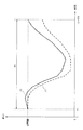
- FIG. 1 is a diagram illustrating an example of a change in the amount of power stored in the power storage device during the stabilization control period.
- FIG. 2 is a diagram illustrating a power command value correction method described in Patent Document 1.
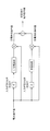
- FIG. 3 is a diagram showing an outline of the charge / discharge control device according to the present embodiment.
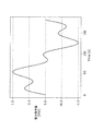
- FIG. 4 is a diagram illustrating an example of the power command value.
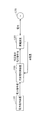
- FIG. 5 is a block diagram showing the configuration of the charge / discharge control apparatus according to the present embodiment.
- FIG. 6 is a flowchart showing the operation of the charge / discharge control device.
- FIG. 7 is a flowchart showing the operation of the correction power amount calculation unit.
- FIG. 8 is a diagram illustrating an example of the planned power storage amount and the actual power storage amount.
- FIG. 8 is a diagram illustrating an example of the planned power storage amount and the actual power storage amount.
- FIG. 9 is a flowchart showing the operation of the correction method selection unit.
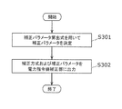
- FIG. 10 is a flowchart showing the operation of the parameter determination unit.
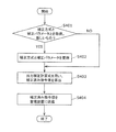
- FIG. 11 is a flowchart showing the operation of the power command value correction unit.
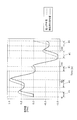
- FIG. 12 is a diagram illustrating a relationship between the power command value and the corrected command value when the first correction method is used when the correction power amount is a positive value.
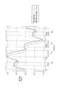
- FIG. 13 is a diagram illustrating a relationship between the power command value and the corrected command value when the first correction method is used when the correction power amount is a negative value.
- FIG. 14 is a diagram illustrating a relationship between a power command value and a corrected command value when the first correction method according to the second modification is used when the correction power amount is a positive value.
- FIG. 15 is a diagram illustrating a relationship between the power command value and the corrected command value when the first correction method according to the third modification is used when the correction power amount is a positive value.
- FIG. 16 is a diagram illustrating a relationship between the power command value and the corrected command value when the second correction method is used when the correction power amount is a positive value.
- FIG. 17 is a diagram illustrating a relationship between the power command value and the corrected command value when the third correction method is used when the correction power amount is a positive value.
- FIG. 18 is a diagram illustrating a relationship between the power command value and the corrected command value when the fourth correction method is used when the correction power amount is a positive value.
- the power storage device may not be able to continue charging and discharging when charging and discharging are performed according to the power command value.
- FIG. 1 is a diagram illustrating an example of a change in the amount of power stored in the power storage device during the stabilization control period (frequency control period).
- the vertical axis indicates the charged amount
- the horizontal axis indicates time.
- the power storage amount of the power storage device at time t1 + D1 should substantially match the power storage amount at time t1. It is. However, in reality, a power conversion loss or the like occurs in an inverter or the like during power charging / discharging. For this reason, as shown in the graph 12 of FIG. 1, the power storage amount of the power storage device at time t1 + D1 is lower than the power storage amount at time t1. In this case, the power storage device may not be able to be discharged due to a decrease in the amount of power stored.
- Patent Literature 1 corrects the power command value (output command value) using the charge / discharge efficiency value for the above-described problem, and uses less power than the power value indicated by the power command value when the power storage device is discharged.
- a method is disclosed in which the amount of power stored in the power storage device is maintained by charging more power than the power value indicated by the power command value when discharging and charging the power storage device.
- FIG. 2 is a diagram showing a power command value correction method described in Patent Document 1.
- the corrected power command value is obtained by dividing the power command value by the charging efficiency. Used as On the other hand, when the power command value is a positive value, that is, when the power command value indicates discharge of the power storage device (discharge command), a value obtained by multiplying the power command value by the discharge efficiency is used as the corrected power command value. .
- the output quality is quantitatively calculated as a performance score by the grid operator.
- the performance score has three values of “delay”, “correlation”, and “accuracy” of the power value (output value) of the power actually output from the power storage device with respect to the power command value. Evaluated by weighted sum of evaluation values.
- “delay degree” represents delay
- “correlation degree” represents waveform similarity
- “accuracy” represents degree of similarity in output magnitude.
- the method of correcting the electric power value using the charging / discharging efficiency value described in Patent Document 1 is intended to maintain the charged amount. For this reason, in the above method, it is not possible to realize highly accurate storage amount control that increases or decreases the storage amount by an arbitrary amount.
- the above performance score indicates that the higher the value, the higher the contribution to the stabilization of the power system.
- the performance score calculation method differs depending on the grid operator. Also, in the long term, the performance score calculation method may sufficiently change according to changes in the status of the power system.
- the power command value correction method described in Patent Document 1 does not consider the performance score calculation method, and the performance score tends to be low.
- a charge / discharge control method controls charge / discharge of a power storage device connected to the power system during a power stabilization control period of the power system.
- a charge / discharge control method wherein a reception step of receiving a power command value indicating a power value of power to be charged / discharged to the power storage device during the stabilization control period, a remaining power storage amount of the power storage device, and the power storage An acquisition step of acquiring a target power storage amount that is a target value of the power storage amount of the device; and a control step of performing control to charge / discharge the power storage device according to the power command value when the power command value is received.
- a delay time is determined according to a difference between the target power storage amount and the remaining power storage amount, the power command value indicating discharge of the power storage device is a positive value, and charging of the power storage device is performed. Indicating the above When the force command value is a negative value, (i) when the remaining power storage amount is smaller than the target stored power amount, the power command value is increased during the period when the power command value increases. And (ii) when the remaining amount of storage is greater than the target amount of storage, the power command is controlled. In a period in which the value decreases with the passage of time, control is performed to charge / discharge the power storage device according to the power command value at a timing when the delay time has elapsed from when the power command value is received.
- the delay time may be determined to be longer as the difference between the target power storage amount and the remaining power storage amount is larger.
- the delay time is determined to be a smaller time as the size of the power storage device increases, and at the timing when the delay time has elapsed since the reception of the first power command value, the power storage device is in accordance with the first power command value. You may control charging / discharging.
- a predicted command value for predicting a future power command value is calculated using a history of the power command value received in the past, and (i) the remaining power amount is calculated from the target charged amount Is smaller, the prediction command value corresponding to the power command value corresponds to the power command value at a timing when the delay time has elapsed since the power command value was received in a period in which the prediction command value increases with time.
- the delay time from when the power command value is received in a period in which the power storage device is charged and discharged according to the predicted command value and the predicted command value corresponding to the power command value decreases with time.
- the amount of remaining power is determined according to the predicted command value corresponding to the power command value.
- the power storage amount is larger than the target power storage amount, the power is calculated at the timing when the delay time has elapsed since the power command value was received in a period in which the predicted command value corresponding to the power command value decreases with time. Control is performed to charge / discharge the power storage device according to the predicted command value corresponding to the command value, and the power command value is received in a period in which the predicted command value corresponding to the power command value increases with time.
- the power storage device may be charged / discharged according to the predicted command value corresponding to the power command value at a timing preceding the delay time from time to time.
- the amount of stored electricity can be controlled at higher speed.
- the remaining power storage amount is acquired at a predetermined cycle
- the target power storage amount may be a target value of the power storage amount after a predetermined time has elapsed from the timing at which the remaining power storage is acquired.
- the delay time may be determined to be shorter than a predetermined upper limit time.
- the delay time may include a time from when the power command value is received until charging and discharging of the power storage device is started according to the power command value.
- the storage amount can be controlled efficiently.
- the charge / discharge control method is a charge / discharge control method for controlling charge / discharge of a power storage device connected to the power system during a power stabilization control period of the power system, During the stabilization control period, a reception step of receiving a power command value indicating a power value of power to be charged / discharged to the power storage device, a remaining power storage amount of the power storage device, and a target value of a power storage amount of the power storage device An acquisition step of acquiring a certain target power storage amount; and (i) when the remaining power storage amount is smaller than the target power storage amount, the power value indicating charging, and the absolute value of the power value indicated by the power command value is A first offset power value, which is a power value whose absolute value increases as the value decreases, is determined, and the power of the power value obtained by adding the first offset power value and the power value indicated by the power command value is stored in the power storage.
- the second value is a power value indicating discharge, and the absolute value increases as the absolute value of the power value indicated by the power command value decreases.
- the amount of power stored in the power storage device can be controlled while suppressing the deterioration of the “correlation” in the performance score.
- the charge / discharge control method is a charge / discharge control method for controlling charge / discharge of a power storage device connected to the power system during a power stabilization control period of the power system, During the stabilization control period, a power command value indicating a power value of power to be charged / discharged to the power storage device is received, and a target power storage that is a target value of a remaining power storage amount of the power storage device and a power storage amount of the power storage device A predetermined time is determined according to an acquisition step of acquiring an amount, and a difference between the target power storage amount and the remaining power storage amount, and (i) when the remaining power storage amount is smaller than the target power storage amount, In a period in which the command value indicates discharge, charging and discharging of the power storage device is stopped for the predetermined time every predetermined cycle. (Ii) When the remaining power storage is larger than the target power storage amount, the power command Predetermined during the period when the value indicates charging It said predetermined time for each period, to stop the
- the charge / discharge control method is a charge / discharge control method for controlling charge / discharge of a power storage device connected to the power system during a power stabilization control period of the power system,
- a receiving step of receiving a power command value indicating a power value of power to be charged / discharged in the power storage device during the stabilization control period, a power storage amount of the power storage device, and a target value of the power storage amount of the power storage device An acquisition step of acquiring a target power storage amount, and when a power value indicating discharge of the power storage device is a positive value and a power value indicating charging of the power storage device is a negative value, (i) When the remaining power storage amount is smaller than the target power storage amount, the first offset power value is a power value indicating charging, and the power value indicated by the power command value is smaller.
- the power storage device is charged and discharged with a power value obtained by adding the power value indicated by the power command value, and (ii) when the remaining power storage amount is larger than the target power storage amount,
- the second offset power value which is a power value that increases as the power value indicated by the power command value decreases, is determined, and the power value indicated by the second offset power value and the power command value.
- the amount of power stored in the power storage device can be controlled while suppressing the deterioration of the “correlation” in the performance score.
- the charge / discharge of the power storage device connected to the power system is responded to the power command value of the charge / discharge during the power stabilization control period of the power system.
- a charge / discharge control method for controlling based on a performance score indicating a property wherein during the stabilization control period, a reception step of receiving a power command value indicating a power value of power to be charged / discharged to the power storage device; An acquisition step of acquiring a remaining power storage amount of the power storage device and a target power storage amount that is a target value of the power storage amount of the power storage device; and when the power command value is received, the power storage device is charged according to the power command value.
- a control step for performing control to discharge wherein the performance score includes a power value indicated by the power command value and power of power charged / discharged from the power storage device according to the power command value.
- the control step based on the weight of the performance score, a first control method, a second control method, and a third
- the charge / discharge of the power storage device is controlled according to one control method selected from among the control methods, and in the first control method, a delay time is determined according to a difference between the target power storage amount and the remaining power storage amount.
- the power storage device When the power command value indicating the discharge of the power storage device is a positive value and the power command value indicating the charge of the power storage device is a negative value, (i) If the power command value is smaller than the target power storage amount, the power storage device is charged according to the power command value at a timing when the delay time has elapsed since the power command value was received in a period in which the power command value increases with time. Release (Ii) when the remaining amount of power storage is greater than the target power storage amount, the delay time from when the power command value is received in a period in which the power command value decreases over time. Control is performed to charge and discharge the power storage device according to the power command value at the elapsed time.
- a predetermined time is determined according to the difference between the target power storage amount and the remaining power storage amount, and (i) When the remaining amount of power storage is smaller than the target power storage amount, charging and discharging of the power storage device is stopped for the predetermined time for each predetermined period in a period in which the power command value indicates discharge; (ii) When the remaining amount of power storage is larger than the target power storage amount, charging and discharging of the power storage device is stopped for the predetermined time every predetermined period in a period in which the power command value indicates charging.
- a recording medium such as a system, an apparatus, an integrated circuit, a computer program, or a computer-readable CD-ROM, and the system, apparatus, integrated circuit, and computer program. And any combination of recording media.
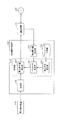
- FIG. 3 is a diagram illustrating an outline of the charge / discharge control device according to the first embodiment.
- the charge / discharge control device 100 receives the power command value output from the power command device 110 during a predetermined stabilization control period, and outputs the corrected power command value to the power storage device 120. It is a device that controls charging / discharging of power storage system 120 of power storage device 120.
- the stabilization control period is described as including a plurality of steps, with a 10-minute period as one step.
- the charge / discharge control device 100 acquires the amount of power stored from the power storage device 120 to charge / discharge the power storage device 120 that organically cooperates with the power storage device 120 and follows the power command value. To control the amount of electricity stored. That is, the charge / discharge control device 100 and the power storage device 120 constitute a power storage control system.
- the power storage device 120 is a device having the ability to store and release electrical energy, specifically, a secondary battery such as a lead storage battery, a lithium ion battery, a redox flow battery, a flywheel, a pumped-storage generator, and the like. .
- a secondary battery such as a lead storage battery, a lithium ion battery, a redox flow battery, a flywheel, a pumped-storage generator, and the like.
- the power command device 110 is a device owned by the grid operator, and transmits a power command value to the charge / discharge control device 100 in order to control the frequency of the power grid 130 to be constant.
- the charge / discharge control apparatus 100 can be realized not only by a microcomputer, a DSP, and a system LSI, but also by a general-purpose computer, server, or cloud on the Internet.
- FIG. 4 is a diagram showing an example of the power command value.
- the horizontal axis represents time
- the vertical axis represents the power command value.
- the power command value is the power value itself of the power that power storage device 120 needs to charge and discharge according to the power command value.
- the power command value when the power command value is a positive value (+), the power storage device 120 is instructed to discharge, and when the power command value is a negative value ( ⁇ ), the power storage device 120 is charged. Is a command value for commanding.
- the power storage device 120 performs a larger amount of charge / discharge.
- the power storage device 120 can output power in the range of ⁇ 1.0 MW. That is, as shown in FIG. 4, the upper limit value of the power command value is +1.0 MW, and the lower limit value is ⁇ 1.0 MW.
- the power command value is sent to the charge / discharge control apparatus 100 at a cycle of about several seconds, here, at a cycle of 2 seconds.
- the power command value in the stabilization control greatly varies in a short time because it depends on the change in the frequency deviation of the power system 130, but is not biased in one direction. For this reason, when the average value of the power command value is obtained over a long period, it is characterized by ⁇ 0.
- the power command value may indicate a ratio to the maximum value of the output of the power storage device 120 (the above-described ⁇ 1.0 MW, hereinafter also referred to as control capability), not the power value itself.
- the power value of the power charged and discharged by the power storage device 120 according to the power command value is (control capability) ⁇ (ratio indicated by the power command value).
- FIG. 5 is a block diagram showing a configuration of the charge / discharge control apparatus 100 according to the first embodiment.
- the same components as those in FIG. 5 are identical to FIG. 5 in FIG. 5, the same components as those in FIG. 5.
- the charge / discharge control apparatus 100 includes a receiving unit 101, a corrected power amount calculating unit 102, a control unit 103, and a storage unit 104.
- the receiving unit 101 receives a power command value every predetermined period during the stabilization control period. In the present embodiment, receiving section 101 receives a power command value every 2 seconds. In the present embodiment, the power command value is transmitted from power command device 110, but charge / discharge control device 100 may determine the power command value.
- the charge / discharge control apparatus 100 further includes a power command value determination unit that measures the frequency of the AC power of the power system 130 and determines a power command value according to the measured frequency. You may receive the electric power command value which the value determination part determined.
- the corrected power amount calculation unit 102 acquires information on the power storage amount of the power storage device 120 and information on the target power storage amount that is a target value of the power storage amount of the power storage device 120, and calculates the corrected power amount.
- the amount of power storage is represented by, for example, a power storage rate (SOC: State Of Charge).
- the storage unit 104 stores performance score calculation formulas, which will be described later.
- Information such as a performance score calculation formula stored in the storage unit 104 may be stored outside the device of the charge / discharge control device 100 such as a cloud on the Internet. That is, the storage unit 104 is not an essential component.
- the calculation formula of the performance score PS stored in the storage unit 104 is the initial setting in the introduction of the charging / discharging control system using the charging / discharging control device 100, or when the rules of the system operator's performance score calculating formula are changed. Updated.
- the control unit 103 controls the power storage device 120 to charge / discharge the power of the power value indicated by the power command value every time the receiving unit 101 receives the power command value. In other words, the control unit 103 performs control to charge / discharge the power of the power value indicated by the power command value when the receiving unit 101 receives the power command value.
- “when the receiving unit 101 receives a power command value” means that it is inevitable until the power storage device 120 is charged and discharged according to the power command value after the receiving unit 101 receives the power command value. It means a predetermined timing including a delay time and the like.
- the control unit 103 includes a correction method selection unit 105, a parameter determination unit 106, and a power command value correction unit 107.
- the correction method selection unit 105 selects a power command value correction method based on a performance score calculation formula for quantitatively calculating the output quality of the power storage device 120.
- the parameter determination unit 106 determines a correction parameter for correcting the power command value based on the correction power amount calculated by the correction power amount calculation unit 102 and the correction method selected by the correction method selection unit 105.
- the power command value correcting unit 107 corrects the power command value acquired from the power command device 110 by the receiving unit 101 using the correction method and the correction parameter, and outputs the corrected command value to the power storage device 120.
- the performance score quantitatively indicates the output quality of the output value of the power storage device 120 with respect to the power command value.
- the performance score PS is expressed by Expression (1) using the three evaluation values D, A, and P.
- D is a delay degree indicating the degree of delay of the output value of the power storage device 120 with respect to the power command value (the power value of the power actually output from the power storage device 120), and A is the power command value and the power storage value.
- the degree of correlation indicating the degree of correlation between the output values of device 120, and P is the accuracy depending on the error between the power command value and the output value of power storage device 120.
- K i is a weighting coefficient of each evaluation value, and is a real number of 0 or more that satisfies Expression (2).
- the delay degree D is calculated using Equation (3), where ⁇ is the delay time of the output value of the power storage device 120 with respect to the power command value of the power storage device 120, and T is the longest possible delay time.
- delay time ⁇ is a time difference between waveforms when the waveform of the power command value and the waveform of the output value of power storage device 120 are shifted little by little and the degree of correlation between the two is maximized. .
- Correlation degree A is calculated using equation (4) using correlation function ⁇ .
- r is a power command value
- yt ⁇ is a value obtained by translating the output value of the power storage device 120 backward by a delay time ⁇ . That is, in the correlation degree A, the influence of the delay time ⁇ is removed.
- the accuracy P is calculated using Equation (5).
- r is a power command value
- y is an output value of the power storage device 120. That is, accuracy P is a value obtained by subtracting an error rate between the power command value and the output value of power storage device 120 from 1.
- the delay degree, correlation degree, and accuracy take values from 0.0 to 1.0, respectively, and the closer to 1.0, the better the output quality. Further, as shown in the equations (1) and (2), the performance score PS similarly takes values from 0.0 to 1.0, and the closer to 1.0, the better the output quality is.
- the weighting factor k i of each evaluation value varies depending on the power system 130 to be stabilized, and the weighting factor k i is determined by the grid operator.
- the performance score PS in which the value of the weighting factor k i is a parameter will be described as described above.
- the calculation formula for the performance score PS may be another calculation formula, and the calculation of the formula (1) It is not limited to a formula.
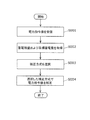
- FIG. 6 is a flowchart showing the operation of the charge / discharge control apparatus 100.
- the receiving unit 101 receives a power command value (S001).
- the corrected power amount calculation unit 102 acquires the remaining power storage amount and the target power storage amount of the power storage device 120 (S002). More specifically, the corrected power amount calculation unit 102 calculates the corrected power amount from the difference between the remaining power storage amount (actual power storage amount) and the target power storage amount (predetermined power storage amount).
- control unit 103 selects a correction method for the power command value based on the performance score calculation formula (S003).
- control unit 103 (power command value correction unit 107) corrects the power command value by the selected correction method, and outputs the corrected command value to power storage device 120 (S004).
- the corrected power amount calculation unit 102 calculates the corrected power amount from the difference between the actual power storage amount of the power storage device 120 and a predetermined power storage amount (target power storage amount) in order to control the power storage amount of the power storage device 120.
- the predetermined power storage amount is a constant power storage amount or a power storage amount (planned power storage amount) that changes according to the time, which is planned in advance by an administrator of the power storage control system.
- the corrected power amount calculation unit 102 calculates the corrected power amount from the difference between the actual power storage amount of the power storage device 120 and the planned power storage amount.
- the corrected power amount is a power amount that indicates how much (or less) the power value of the power storage device 120 should be charged / discharged than the power value indicated by the power command value during one step.
- the correction power amount calculation unit 102 preferably calculates the correction power amount at a frequency of about once per step during the stabilization control period, but may be less than about once per step. Good.
- the stabilization control period is composed of a continuous step 1, step 2... Step n, with a 10 minute period as one step.
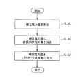
- FIG. 7 is a flowchart showing the operation of the corrected power amount calculation unit 102.
- the corrected power amount calculation unit 102 uses the equation (6) at the start time of each step, and based on the difference between the planned power storage amount and the actual power storage amount acquired from the power storage device 120, the corrected power amount of the step.
- the amount is calculated (S101).
- x n is the correction amount of power in step n
- C n is planned storage amount
- c n is the charged amount at that step
- T c is the time in one step
- T e is corrected the difference It is a predetermined time set to do.
- T c is 10 minutes and Te is 60 minutes.
- FIG. 8 is a diagram illustrating an example of the planned power storage amount and the actual power storage amount.
- the corrected power amount calculation unit 102 calculates the corrected power amount in step 1.
- Planning storage amount at this time is C 1
- the actual storage amount are the c 1
- the x n (C 1 -c 1 ) ⁇ T c / T e.
- the corrected power amount calculation unit 102 recorrects the corrected power amount xn calculated by the equation (6) using the equation (7) (S102).
- L is an amount of electric power (conversion loss electric energy) corresponding to one step of an average loss of electric power generated when charging / discharging the electric power system 130 of the power storage device 120.
- the corrected power amount calculation unit 102 does not have to add the conversion loss power amount in step S102.
- the corrected power amount calculation unit 102 outputs the corrected power amount xn calculated using Expression (6) (and Expression (7)) to the parameter determination unit 106 (S103).
- the correction method selection unit 105 selects a correction method for the power command value based on the calculation formula for the performance score PS stored in the storage unit 104.
- the correction method selecting section 105 selects a correction method of a power command value based a part of calculation formula in the weighting factor k i of each evaluation.
- the correction method selection unit 105 includes a first correction method (correction method M 1 ) that prioritizes the correlation degree A and the accuracy P, and a second correction method (correction method M 2 ) that prioritizes the correlation degree A. , And a third correction method (correction method M 3 ) giving priority to accuracy P, one correction method is selected.
- FIG. 9 is a flowchart showing the operation of the correction method selection unit 105.
- the correction method selection unit 105 acquires the weight coefficient k i of each evaluation value of the calculation formula for the performance score PS from the storage unit 104 (S201).
- the correction method selection unit 105 determines a power command value correction method using a discriminant function with each weight coefficient as a variable (S202).
- the discriminant function is a function based on a linear combination of a weight coefficient k i that is a variable in the discriminant function and a linear discriminant coefficient.
- the discriminant function is obtained by discriminant analysis.
- the correction method selection unit 105 selects the correction method m from the correction method candidates M i using the sign of the discriminant function f Li as shown in the equation (8).
- the correction method selection unit 105 uses the following three discriminant functions as the discriminant function f Li .
- k 1 is a weighting factor that is multiplied by the degree of delay D
- k 2 is a weighting factor that is multiplied by the degree of correlation A
- k 3 is a weighting factor that is multiplied by the accuracy A. .
- the correction method selecting section 105 selects the correction method M 1.
- the correction method selecting unit 105 selects a correction method M 2. If the condition is satisfied the discriminant function f L3 represented by the formula (11) is shown in equation (8), i.e., if the weighting factor k 3 precision P is greater than the other weighting factors, the correction method selecting section 105 , to select a correction method M 3.
- the correction method selection unit 105 selects a correction method that returns a value having the largest discriminant function value.
- correction method selection unit 105 outputs the selected correction method m to the parameter determination unit 106 (S203).
- the charge / discharge control device 100 ensures the responsiveness of the output of the power storage device 120 to the power command value by changing the correction method m of the power command value according to the calculation formula of the performance score PS, and The amount of power stored in the power storage device 120 can be controlled.
- the parameter determination unit 106 uses the correction power amount xn calculated by the correction power amount calculation unit 102 and the correction method m selected by the correction method selection unit 105 to determine a correction parameter for correcting the power command value. decide.
- the correction parameter differs depending on the correction method m selected by the correction method selection unit 105, and details will be described later.
- the parameter determination unit 106 desirably determines the parameter every time the correction power amount x n is acquired from the correction power amount calculation unit 102, but the parameter determination unit 106 does not have to determine the parameter every time the correction power amount x n is acquired. Also good.
- FIG. 10 is a flowchart showing the operation of the parameter determination unit 106.
- the parameter determination unit 106 determines a correction parameter using a correction parameter calculation formula, which is a formula using the correction scheme m and the correction power amount xn as arguments, as shown in Formula (12) (S301).
- pn is a correction parameter
- fp is a correction parameter calculation formula
- the correction parameter p n is the delay time.
- Parameter determining section 106 a correction parameter calculation equation f p, for example, to determine the correction parameters using the following equation (13).
- k o is an open loop gain, which is a positive real number.
- Equation (13) means that the delay time becomes longer as the correction power amount is larger.
- the value of k o is determined by tuning when the charge / discharge control device 100 is designed.
- the correction method m M 1
- the relationship between the correction power amount x n and the delay time (correction parameter p n ) is stored in advance in the storage unit 104 as a table, and the parameter determination unit 106
- the delay time may be determined with reference to FIG.
- the parameter determination unit 106 outputs the correction method m and the correction parameter pn to the power command value correction unit 107 (S302).
- the power command value correction unit 107 corrects the power command value acquired from the power command device 110 by the reception unit 101 using the correction method m and the correction parameter pn, and outputs the corrected command value to the power storage device 120. .
- the power command value correcting unit 107 preferably generates and outputs a corrected command value every time the receiving unit 101 receives the power command value, but the corrected command value every time the receiving unit 101 receives the power command value. It is not necessary to generate and output.
- FIG. 11 is a flowchart showing the operation of the power command value correction unit 107.
- the power command value correcting section 107 obtains a correction method m a correction parameter p n from the parameter determination unit 106 (S401).
- the power command value correction unit 107 includes the power command value correction unit 107. inside held as a variable correction scheme m or updating the correction parameter p n is the (S402). Obtained when the correction method m a correction parameter p n is not intended any new (No in S401), the power command value correcting section 107, the processing of step S403 without updating the correction method m and the correction parameter p n Migrate to
- the power command value correcting section 107 is shown in equation (14), using the correction method m, and correction parameters p n, the output correction calculation formula is a formula that uses a power command value y t as an argument
- the corrected command value is calculated (S403).
- y t ′ is a corrected command value at time t
- f y is an output correction calculation formula
- the power command value correction unit 107 transmits the corrected command value y t ′ to the power storage device 120 (S404).
- Correction method M 1 is selected when f L1 of the formula (9) may satisfy the condition of the expression (8), i.e., the weight coefficient k 1 of the delay D is smaller than the other weight coefficient .
- Figure 12 is a diagram illustrating the power command value when using the correction scheme M 1 when the correction amount of power x n is a positive value, the relationship between the corrected command value.
- the vertical axis represents the command value
- the horizontal axis represents time.
- the power command value is indicated by a broken line
- the corrected command value is indicated by a solid line.
- the power command value correction unit 107 charges and discharges the power of the power value indicated by the power command value after the delay time elapses during the period in which the power command value increases with time (period a1 shown in FIG. 12).
- the corrected command value is generated as described above.
- the period in which the power command value increases with time means a period in which the discharge amount of the power storage device 120 increases. Therefore, by providing a delay time in this period, it is possible to suppress discharge, and thus the charge / discharge control device 100 Can suppress a decrease in the amount of power stored in the power storage device 120.
- Figure 13 is a diagram illustrating the power command value when using the correction scheme M 1 when the correction amount of power x n is a negative value, the relationship between the corrected command value.
- the vertical axis represents the command value
- the horizontal axis represents time.
- the power command value is indicated by a broken line
- the corrected command value is indicated by a solid line.
- the power command value correction unit 107 charges / discharges the power of the power value indicated by the power command value after the delay time elapses in the period (period a2 shown in FIG. 12) in which the power command value decreases with time.
- the corrected command value is generated as described above.
- the period in which the power command value decreases with time means a period in which the amount of charge of the power storage device 120 increases. Therefore, charging can be suppressed by providing a delay time in such a period. Device 100 can suppress an increase in the amount of electricity stored in power storage device 120.
- the correction method M 1 is selected is when the weighting factor k 1 of the delay D is smaller than the other weighting factor. That is, as shown in FIGS. 12 and 13, even if the delay time is provided, the influence on the performance score PS is small. Therefore, the charge / discharge control device 100 can control the amount of power stored in the power storage device 120 while maintaining the output quality.
- the correction parameter p n to determine the parameter determination unit 106, a delay time.
- the parameter determination unit 106 determines a delay time proportional to the correction amount of power x n as the correction parameter p n. Accordingly, when the correction power amount xn is a negative value, the delay time is also a negative value.
- an upper limit may be set for a delay time from when the power command value is received until charging / discharging according to the power command value received by the power storage device 120 is performed.
- the parameter determination unit 106 does not calculate the delay time using a linear equation such as the equation (13), but the parameter determination unit 106 uses the equation (13 ′) in which an upper limit value is provided for the delay time.
- the delay time may be calculated by an expression such as When the parameter determination unit 106 calculates the delay time using the equation (13 ′), the delay time is within a predetermined range no matter how large the correction power amount xn is.
- p max is an upper limit value of the delay time.
- power command value correcting portion 107 calculates a corrected command value by using the output correction equation f y represented by formula (15).
- min is a function that returns the minimum value of the argument interval
- max is a function that returns the maximum value of the argument interval. For example, when the delay time (correction parameter p n ) is +6 seconds, the minimum power command value among the power command values 6 seconds before the current power command value becomes the corrected command value.
- the corrected command value is the same as the command value provided with a delay by the delay time only during the period when the power command value increases with time (when the output rises). Become. Further, when the delay time is a negative value, the command value is provided with a delay by the delay time only in a period (when the output is lowered) in which the power command value decreases with time.
- the delay time (correction parameter p n ) may include a time (T d ) from when the power command value is received until charging and discharging of the power storage device 120 is started according to the power command value.
- the charge / discharge control apparatus 100 can correct the power command value based on the performance score calculation method. As a result, the output quality can be maintained and the amount of power stored in the power storage device 120 can be controlled.
- the parameter determination unit 106 of the charge / discharge control apparatus 100 acquires the actual correction power amount in the past predetermined period from the power command value correction unit 107. Further, parameter determining section 106 determines the deviation e n by using the difference between the actual correction amount of power calculated the corrected amount of power x n and the past predetermined period in the past predetermined period. Parameter determining section 106, that the deviation e n controls the correction parameter p n to be close to 0, increase the accuracy of future correction power.
- the parameter determination unit 106 uses the equation (16) of the PI control (feedback control) in the discrete time system instead of the open loop control equation such as the equation (13) to set the correction parameter pn . calculate.
- p n the correction parameter p n, e n in step n, the deviation (correction power amount - actual correction amount of power), Delta] t is the sampling time
- K p is the proportional coefficient
- K i is the integral It is a coefficient.
- the parameter determination unit 106 may determine the correction parameter p n to approximate the long-term zero deviation of the actual correction amount of power and the correction amount of power x n of the power storage device 120 The accuracy of the corrected power amount in the future can be improved.
- the parameter determination unit 106 of the charge / discharge control device 100 receives the power command value for the delay time (correction parameter p n ) using the change amount of the power command value in the correction method M 1 described above. Determine dynamically.
- the parameter determination unit 106 determines the delay time of the power command value (first power command value), the change from the latest power command value (second power command value) of the power command value.
- the amount may be calculated.
- the parameter determination unit 106 shortens the delay time when the magnitude of the change amount of the power command value is large, and lengthens the delay time when the magnitude of the change amount is small.
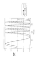
- the corrected command value determined in this way and the power command value have a relationship as shown in FIG. 14 when the corrected power amount xn is a positive value. In FIG. 14, the delay time is shortened with a change in the power command value at around time 80 (s).
- the change amount may be a change amount with respect to a power command value received before the current power command value, or an average value of power command values received in a predetermined period before the current power command value It may be a change amount with respect to.
- the power command value correction unit 107 of the charge / discharge control apparatus 100 predicts a future power command value using the history of the power command value received in the past in the correction method M 1 described above. Is calculated.
- the history of power command values received in the past is stored in the storage unit 104 or the like.
- the power command value correcting unit 107 delays from the time when the power command value is received in a period (first period) in which the predicted command value increases with time. At the timing after the elapse of time, the corrected command value is generated so that the power of the power value indicated by the predicted command value corresponding to the power command value is charged / discharged.
- the power command value correction unit 107 receives the power command value in a period (second period) in which the predicted command value decreases with time.
- the corrected command value is generated so that the power of the power value indicated by the predicted command value corresponding to the power command value is charged / discharged at a timing preceding the delay time from.
- the corrected command value determined in this way and the power command value have a relationship as shown in FIG.
- the power command value correction unit 107 precedes the delay time from the reception of the power command value in a period in which the predicted command value increases with time. At the timing, the corrected command value is generated so that the power of the power value indicated by the predicted command value corresponding to the power command value is charged and discharged.
- the power command value correction unit 107 when the corrected power amount xn is a negative value, the power command value correction unit 107, after the delay time elapses from when the power command value is received, in a period in which the predicted command value decreases with time. At this timing, the corrected command value is generated so that the power of the power value indicated by the predicted command value corresponding to the power command value is charged and discharged.
- the power command value correction unit 107 according to the modification example 3 generates a corrected command value using an equation (15 ′) that is a variation of the equation (15).
- the corrected command value is generated using Expression (15 ′)
- the corrected power amount x n is a positive value.
- the amount of discharge becomes smaller.
- the correction power amount xn is a negative value, the charge amount is increased. For this reason, the charge / discharge control apparatus 100 which concerns on the modification 3 can control the electrical storage amount at higher speed.
- Correction method M 2 when f L2 of the formula (10) satisfies the condition of formula (8), that is selected when the weight coefficient k 2 of the correlation degree A higher than other weighting factor . At this time, not degrading the correlation degree A as much as possible prevents the performance score from deteriorating.
- Correction method M 2 is increased and the power command value, as the correlation value A between the power command value power storage device 120 is actually output is not deteriorated, the power instruction value a power command value around the time of near 0 ⁇ Or, it is a correction method for correcting to a corrected corrected power command value.
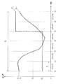
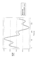
- FIG. 16 when the correction amount of power x n is a positive value, a diagram illustrating the power command value when using the correction scheme M 2, the relationship between the corrected command value.
- the vertical axis represents the command value
- the horizontal axis represents time.
- the power command value is indicated by a broken line
- the corrected command value is indicated by a solid line.
- the power command value correction unit 107 calculates a power value obtained by adding a power value (first offset power value) indicating charging to a power value indicated by the power command value as a corrected command value. That is, the first offset power value is a negative sign power value.
- the power command value correction unit 107 determines the first offset power value so that the absolute value increases as the absolute value of the power value indicated by the power command value decreases.
- the power command value correcting section 107 in the period around the upper limit value and near the lower limit power command value, to reduce the correction amount of the power command value, the power instruction value approaches ⁇ 0 As the power command value is corrected, the correction amount is increased. This is because the degree of correlation A does not deteriorate so much by using such a correction method.
- the power command value correction unit 107 calculates a power value obtained by adding a power value indicating discharge (second offset power value) to the power value indicated by the power command value as the corrected command value.
- the second offset power value is a positive sign power value.
- the power command value correction unit 107 determines the second offset power value so that the absolute value increases as the absolute value of the power value indicated by the power command value decreases.
- the correction parameter p n to determine the parameter determination unit 106 a decrease coefficient.
- Parameter determining section 106 for example, as shown in the above equation (13), to determine increased or decreased factor proportional to the correction amount of power x n as the correction parameter p n.
- the power command value correcting portion 107 calculates the corrected power command value by using the output correction equation f y as shown in equation (17).
- y t is a power command value
- pn is an increase / decrease coefficient (correction parameter)
- y ′ t is a corrected command value.
- the power instruction value y t is ⁇ 1.0
- corrected command value y 't is equal to the y t when y t is 0.0
- the corrected command value y' t the power smaller than the command value y t by increasing or decreasing the coefficient p n.
- the power command value correcting portion 107 calculates a corrected command value by using the output correction equation f y as shown in equation (17).
- the corrected command value y ′ t has characteristics as shown in FIG.
- the correction method M 2 while suppressing the deterioration of the correlation degree A in the performance score, it is possible to control the storage amount of the power storage device 120. That is, in the stabilization control method for calculating a performance score correlation A is emphasized is applied, the correction method M 2 is effective.
- Correction method M 3 are, f L3 of formula (11) may satisfy the condition of the expression (8), i.e., the weighting factor k 3 precision P is selected when larger than the other weighting factor. At this time, not degrading the accuracy P as much as possible prevents the performance score from deteriorating.
- Correction method M 3 represents only one of the periods of time indicated by the power instruction value period showing a charging or discharging, a correction method for stopping the control of the charging and discharging of the power storage device 120 at specific time intervals.
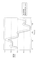
- FIG. 17 when the correction amount of power x n is a positive value, a diagram illustrating the power command value when using the correction scheme M 3, the relationship between the corrected command value.
- the vertical axis represents the command value
- the horizontal axis represents time.
- the power command value is indicated by a broken line
- the corrected command value is indicated by a solid line.
- power command value correction unit 107 stops charging / discharging of power storage device 120 for a predetermined time every predetermined cycle in a period in which the power command value indicates discharge.
- power command value correction unit 107 stops charging / discharging of power storage device 120 for a predetermined time every predetermined cycle in a period in which the power command value indicates charging.
- the correction parameter p n to determine the parameter determination unit 106 a predetermined time to stop the charging and discharging of the power storage device 120 (time reduction).
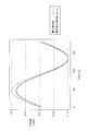
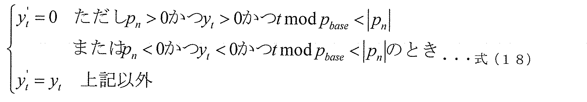
- the power instruction value correction section 107 calculates the corrected power command value by using the output correction equation f y represented by formula (18).
- y t is a power command value
- t is a time
- p base is a period
- pn is a reduction time (correction parameter)
- y ′ t is a corrected command value
- mod is a remainder. It is a function.
- the power command value correcting portion 107 calculates a corrected command value by using the output correction equation f y as shown in equation (18).
- the corrected command value y ′ t has characteristics as shown in FIG.
- the correction method M 3 described above while suppressing the deterioration of the accuracy P in performance score, it is possible to control the storage amount of the power storage device 120. That is, in the stabilization control method for calculating a performance score precision P is important is applied, the correction method M 3 are, it is effective.
- the fourth correction method (correction method M 4 ) will be described in detail.
- Correction method M 4 is a hard correction method aggravate correlation A. Therefore, the correction method M 4, when f L2 of the formula (10) is such as to satisfy the condition of Equation (8), i.e., larger than the weighting coefficient k 2 is other weighting factor for the correlation degree A Sometimes it is good to choose.
- Correction method M 4 includes a power command value, as the correlation value A between the power command value power storage device 120 is actually output is not deteriorated, the power command to the central power command value period near the maximum or minimum value This is a correction method for correcting to a corrected power command value that is increased or decreased.
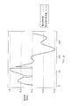
- FIG. 18 when the correction amount of power x n is a positive value, a diagram illustrating the power command value when using the correction scheme M 4, the relationship between the corrected command value.
- the vertical axis represents the command value
- the horizontal axis represents time.
- the power command value is indicated by a broken line
- the corrected command value is indicated by a solid line.
- the power command value correction unit 107 calculates a power value obtained by adding a power value (first offset power value) indicating charging to a power value indicated by the power command value as a corrected command value. That is, the first offset power value is a negative sign power value.
- the power command value correction unit 107 determines the first offset power value so that the value decreases (becomes negative) as the power value indicated by the power command value increases.
- the power command value correction unit 107 calculates a power value obtained by adding a power value indicating discharge (second offset power value) to the power value indicated by the power command value as the corrected command value. That is, the second offset power value is a positive sign power value.
- the power command value correction unit 107 determines the second offset power value such that the smaller the power value indicated by the power command value, the larger (plus) the value.
- the power instruction value correcting section 107 in the period around the upper limit value and near the lower limit electric power command value, to increase the correction amount of the power command value, the power instruction value approaches ⁇ 0 Accordingly, the correction amount of the power command value is reduced. This is because the degree of correlation A does not deteriorate so much by using such a correction method.
- the correction parameter p n to determine the parameter determination unit 106 a decrease coefficient.
- Parameter determining section 106 for example, as shown in the above equation (13), to determine increased or decreased factor proportional to the correction amount of power x n as the correction parameter p n.
- the power instruction value correction section 107 calculates the corrected power command value by using the output correction equation f y as shown in equation (19).
- y t is a power command value
- pn is an increase / decrease coefficient (correction parameter)
- y ′ t is a corrected command value
- the power command value correcting portion 107 calculates a corrected command value by using the output correction equation f y represented by formula (19).
- the corrected command value y ′ t has characteristics as shown in FIG.
- the correction scheme M 4 is effective.
- each of the above devices can be realized by a computer system including a microprocessor, a ROM, a RAM, a hard disk unit, a display unit, a keyboard, a mouse, and the like.
- a computer program is stored in the RAM or the hard disk unit.
- Each device achieves its functions by the microprocessor operating according to the computer program.
- the computer program is configured by combining a plurality of instruction codes indicating instructions for the computer in order to achieve a predetermined function.
- a part or all of the components constituting each of the above devices may be configured by one system LSI (Large Scale Integration).
- the system LSI is an ultra-multifunctional LSI manufactured by integrating a plurality of components on a single chip, and specifically, a computer system including a microprocessor, ROM, RAM, and the like. .
- a computer program is stored in the ROM.
- the system LSI achieves its functions by the microprocessor loading a computer program from the ROM to the RAM and performing operations such as operations in accordance with the loaded computer program.
- Part or all of the constituent elements constituting each of the above devices may be configured from an IC card or a single module that can be attached to and detached from each device.
- the IC card or module is a computer system that includes a microprocessor, ROM, RAM, and the like.
- the IC card or the module may include the super multifunctional LSI described above.
- the IC card or the module achieves its functions by the microprocessor operating according to the computer program. This IC card or this module may have tamper resistance.
- the present invention may be realized by the method described above. Further, these methods may be realized by a computer program realized by a computer, or may be realized by a digital signal consisting of a computer program.
- the present invention also relates to a computer readable recording medium such as a flexible disk, hard disk, CD-ROM, MO, DVD, DVD-ROM, DVD-RAM, BD (Blu-ray (registered trademark)). ) Disc), or recorded in a semiconductor memory or the like. Moreover, you may implement
- a computer program or a digital signal may be transmitted via an electric communication line, a wireless or wired communication line, a network represented by the Internet, a data broadcast, or the like.
- the present invention is also a computer system including a microprocessor and a memory.
- the memory stores a computer program, and the microprocessor may operate according to the computer program.
- program or digital signal may be recorded on a recording medium and transferred, or the program or digital signal may be transferred via a network or the like, and may be implemented by another independent computer system.
- the charge / discharge control device can maintain the output quality and control the amount of power stored in the power storage device.
- the charge / discharge control device can change the correction method of the power command value based on the calculation method of the performance score indicating the output quality. Therefore, the charge / discharge control device according to the present invention can be applied to applications such as power stabilization control such as voltage control and grid supply and demand control, power storage device control for buildings, condominiums and general households, and power storage control of electrical equipment. It is.
Abstract
Description
背景技術で説明した通り、電力系統の安定化制御において、蓄電装置は、電力指令値に従って充放電を行った場合、充放電を継続できなくなる場合がある。
図3は、実施の形態1に係る充放電制御装置の概要を示す図である。


次に、充放電制御装置100の変形例1について説明する。
次に、充放電制御装置100の変形例2について説明する。
次に、充放電制御装置100の変形例3について説明する。

実施の形態2では、第2の補正方式(補正方式M2)について詳細に説明する。

実施の形態3では、第3の補正方式(補正方式M3)について詳細に説明する。
上記実施の形態1~3においては、補正方式M1、補正方式M2、補正方式M3について説明したが、充放電制御装置100は、これ以外の補正方式を用いてもよい。

以上、実施の形態に係る充放電制御装置(充放電制御方法、充放電制御システム)について説明したが、本発明は、これら実施の形態に限定されるものではない。以下のような場合も本発明に含まれる。
100 充放電制御装置
101 受信部
102 補正電力量算出部
103 制御部
104 記憶部
105 補正方式選択部
106 パラメータ決定部
107 電力指令値補正部
110 電力指令装置
120 蓄電装置
130 電力系統
Claims (19)
- 電力系統の電力の安定化制御期間中に、前記電力系統に接続された蓄電装置の充放電を制御する充放電制御方法であって、
前記安定化制御期間中に、前記蓄電装置に充放電させる電力の電力値を示す電力指令値を受信する受信ステップと、
前記蓄電装置の蓄電残量、および前記蓄電装置の蓄電量の目標値である目標蓄電量を取得する取得ステップと、
前記電力指令値を受信したときに、当該電力指令値に従って、前記蓄電装置に充放電させる制御を行う制御ステップとを含み、
前記制御ステップでは、前記目標蓄電量と前記蓄電残量との差分に応じて遅延時間を決定し、前記蓄電装置の放電を示す前記電力指令値が正の値であり、前記蓄電装置の充電を示す前記電力指令値が負の値であるとしたときに、
(i)前記蓄電残量が前記目標蓄電量よりも小さい場合は、前記電力指令値が時間の経過とともに増加する期間において、前記電力指令値を受信したときから前記遅延時間が経過したタイミングで当該電力指令値に従って前記蓄電装置に充放電させる制御を行い、(ii)前記蓄電残量が前記目標蓄電量よりも大きい場合は、前記電力指令値が時間の経過とともに減少する期間において、前記電力指令値を受信したときから前記遅延時間が経過したタイミングで当該電力指令値に従って前記蓄電装置に充放電させる制御を行う
充放電制御方法。 - 前記制御ステップでは、前記目標蓄電量と前記蓄電残量との差分が大きいほど、前記遅延時間を長い時間に決定する
請求項1に記載の充放電制御方法。 - 前記制御ステップでは、第1の電力指令値を受信したときに、前記第1の電力指令値と、前記第1の電力指令値よりも前に受信した第2の電力指令値との差分の大きさが大きいほど前記遅延時間を小さい時間に決定し、前記第1の電力指令値を受信したときから前記遅延時間が経過したタイミングにおいて、前記第1の電力指令値に従って、前記蓄電装置に充放電させる制御を行う
請求項1または請求項2に記載の充放電制御方法。 - 前記制御ステップでは、さらに、過去に受信した前記電力指令値の履歴を用いて将来の電力指令値を予測した予測指令値を算出し、
(i)前記蓄電残量が前記目標蓄電量よりも小さい場合は、前記電力指令値に対応する前記予測指令値が時間の経過とともに増加する期間において、前記電力指令値を受信したときから前記遅延時間が経過したタイミングで当該電力指令値に対応する前記予測指令値に従って前記蓄電装置に充放電させる制御を行い、かつ、前記電力指令値に対応する予測指令値が時間の経過とともに減少する期間において、前記電力指令値を受信したときから前記遅延時間だけ先行するタイミングで当該電力指令値に対応する前記予測指令値に従って前記蓄電装置に充放電させる制御を行い、(ii)前記蓄電残量が前記目標蓄電量よりも大きい場合は、前記電力指令値に対応する前記予測指令値が時間の経過とともに減少する期間において、前記電力指令値を受信したときから前記遅延時間が経過したタイミングで当該電力指令値に対応する前記予測指令値に従って前記蓄電装置に充放電させる制御を行い、かつ、前記電力指令値に対応する予測指令値が時間の経過とともに増加する期間において、前記電力指令値を受信したときから前記遅延時間だけ先行するタイミングで当該電力指令値に対応する前記予測指令値に従って前記蓄電装置に充放電させる制御を行う
請求項1乃至請求項3のいずれか1項に記載の充放電制御方法。 - 前記取得ステップでは、前記蓄電残量を所定の周期で取得し、
前記目標蓄電量は、前記蓄電残量を取得したタイミングから所定の時間経過後における蓄電量の目標値である
請求項1乃至請求項4のいずれか1項に記載の充放電制御方法。 - 前記制御ステップでは、前記遅延時間を予め定められた上限の時間よりも短い時間に決定する
請求項1乃至請求項5のいずれか1項に記載の充放電制御方法。 - 前記遅延時間には、前記電力指令値を受信してから当該電力指令値に従って前記蓄電装置の充放電が開始されるまでの時間が含まれる
請求項1乃至請求項6のいずれか1項に記載の充放電制御方法。 - 電力系統の電力の安定化制御期間中に、前記電力系統に接続された蓄電装置の充放電を制御する充放電制御方法であって、
前記安定化制御期間中に、前記蓄電装置に充放電させる電力の電力値を示す電力指令値を受信する受信ステップと、
前記蓄電装置の蓄電残量、および前記蓄電装置の蓄電量の目標値である目標蓄電量を取得する取得ステップと、
(i)前記蓄電残量が前記目標蓄電量よりも小さい場合は、充電を示す電力値であって、前記電力指令値が示す電力値の絶対値が小さいほど、絶対値が大きくなる電力値である第1のオフセット電力値を決定し、前記第1のオフセット電力値と、前記電力指令値が示す電力値とを加算した電力値の電力を前記蓄電装置に充放電させ、(ii)前記蓄電残量が前記目標蓄電量よりも大きい場合は、放電を示す電力値であって、前記電力指令値が示す電力値の絶対値が小さいほど、絶対値が大きくなる電力値である第2のオフセット電力値を決定し、前記第2のオフセット電力値と、前記電力指令値が示す電力値とを加算した電力値の電力を前記蓄電装置に充放電させる、制御ステップとを含む
充放電制御方法。 - 電力系統の電力の安定化制御期間中に、前記電力系統に接続された蓄電装置の充放電を制御する充放電制御方法であって、
前記安定化制御期間中に、前記蓄電装置に充放電させる電力の電力値を示す電力指令値を受信し、
前記蓄電装置の蓄電残量、および前記蓄電装置の蓄電量の目標値である目標蓄電量を取得する取得ステップと、
前記目標蓄電量と前記蓄電残量との差分に応じて所定の時間を決定し、(i)前記蓄電残量が前記目標蓄電量よりも小さい場合は、前記電力指令値が放電を示す期間において、所定の周期ごとに前記所定の時間、前記蓄電装置の充放電を停止させ、(ii)前記蓄電残量が前記目標蓄電量よりも大きい場合は、前記電力指令値が充電を示す期間において、所定の周期ごとに前記所定の時間、前記蓄電装置の充放電を停止させる、制御ステップとを含む
充放電制御方法。 - 電力系統の電力の安定化制御期間中に、前記電力系統に接続された蓄電装置の充放電を制御する充放電制御方法であって、
前記安定化制御期間中に、前記蓄電装置に充放電させる電力の電力値を示す電力指令値を受信する受信ステップと、
前記蓄電装置の蓄電量、および前記蓄電装置の蓄電量の目標値である目標蓄電量を取得する取得ステップと、
前記蓄電装置の放電を示す電力値が正の値であり、前記蓄電装置の充電を示す電力値が負の値であるとしたときに、(i)前記蓄電残量が前記目標蓄電量よりも小さい場合は、充電を示す電力値であって、前記電力指令値が示す電力値が大きいほど、値が小さくなる電力値である第1のオフセット電力値を決定し、前記第1のオフセット電力値と、前記電力指令値が示す電力値とを加算した電力値の電力を前記蓄電装置に充放電させ、(ii)前記蓄電残量が前記目標蓄電量よりも大きい場合は、放電を示す電力値であって、前記電力指令値が示す電力値が小さいほど、値が大きくなる電力値である第2のオフセット電力値を決定し、前記第2のオフセット電力値と、前記電力指令値が示す電力値とを加算した電力値の電力を前記蓄電装置に充放電させる、制御ステップとを含む
充放電制御方法。 - 電力系統の電力の安定化制御期間中に、前記電力系統に接続された蓄電装置の充放電を、当該充放電の電力指令値に対する応答性を示すパフォーマンススコアに基づいて制御する充放電制御方法であって、
前記安定化制御期間中に、前記蓄電装置に充放電させる電力の電力値を示す電力指令値を受信する受信ステップと、
前記蓄電装置の蓄電残量、および前記蓄電装置の蓄電量の目標値である目標蓄電量を取得する取得ステップと、
前記電力指令値を受信したときに、当該電力指令値に従って、前記蓄電装置に充放電させる制御を行う制御ステップとを含み、
前記パフォーマンススコアは、前記電力指令値が示す電力値と、当該電力指令値に応じて前記蓄電装置から充放電される電力の電力値との間の、遅延度、相関度、および精度の重み付け和で表され、
前記制御ステップでは、前記パフォーマンススコアの重みに基づいて、第1の制御方式、第2の制御方式、および第3の制御方式のうちから選択した一の制御方式に従って前記蓄電装置の充放電を制御し、
前記第1の制御方式では、
前記目標蓄電量と前記蓄電残量との差分に応じて遅延時間を決定し、前記蓄電装置の放電を示す前記電力指令値が正の値であり、前記蓄電装置の充電を示す前記電力指令値が負の値であるとしたときに、
(i)前記蓄電残量が前記目標蓄電量よりも小さい場合は、前記電力指令値が時間の経過とともに増加する期間において、前記電力指令値を受信したときから前記遅延時間が経過したタイミングで当該電力指令値に従って前記蓄電装置に充放電させる制御を行い、(ii)前記蓄電残量が前記目標蓄電量よりも大きい場合は、前記電力指令値が時間の経過とともに減少する期間において、前記電力指令値を受信したときから前記遅延時間が経過したタイミングで当該電力指令値に従って前記蓄電装置に充放電させる制御を行い、
前記第2の制御方式では、
(i)前記蓄電残量が前記目標蓄電量よりも小さい場合は、充電を示す電力値であって、前記電力指令値が示す電力値の絶対値が小さいほど、絶対値が大きくなる電力値である第1のオフセット電力値を決定し、前記第1のオフセット電力値と、前記電力指令値が示す電力値とを加算した電力値の電力を前記蓄電装置に充放電させ、(ii)前記蓄電残量が前記目標蓄電量よりも大きい場合は、放電を示す電力値であって、前記電力指令値が示す電力値の絶対値が小さいほど、絶対値が大きくなる電力値である第2のオフセット電力値を決定し、前記第2のオフセット電力値と、前記電力指令値が示す電力値とを加算した電力値の電力を前記蓄電装置に充放電させ、
前記第3の制御方式では、
前記目標蓄電量と前記蓄電残量との差分に応じて所定の時間を決定し、(i)前記蓄電残量が前記目標蓄電量よりも小さい場合は、前記電力指令値が放電を示す期間において、所定の周期ごとに前記所定の時間、前記蓄電装置の充放電を停止させ、(ii)前記蓄電残量が前記目標蓄電量よりも大きい場合は、前記電力指令値が充電を示す期間において、所定の周期ごとに前記所定の時間、前記蓄電装置の充放電を停止させる
充放電制御方法。 - 電力系統の電力の安定化制御期間中に、前記電力系統に接続された蓄電装置の充放電を制御する充放電制御装置と、前記蓄電装置とを備え、
前記充放電制御装置は、
前記安定化制御期間中に、前記蓄電装置に充放電させる電力の電力値を示す電力指令値を受信する受信部と、
前記蓄電装置の蓄電残量、および前記蓄電装置の蓄電量の目標値である目標蓄電量を取得する取得部と、
前記受信部が前記電力指令値を受信したときに、当該電力指令値に従って、前記蓄電装置に充放電させる制御を行う制御部とを備え、
前記制御部は、
前記目標蓄電量と前記蓄電残量との差分に応じて遅延時間を決定し、前記蓄電装置の放電を示す前記電力指令値が正の値であり、前記蓄電装置の充電を示す前記電力指令値が負の値であるとしたときに、
(i)前記蓄電残量が前記目標蓄電量よりも小さい場合は、前記受信部が受信する前記電力指令値が時間の経過とともに増加する期間において、前記電力指令値を受信したときから前記遅延時間が経過したタイミングで当該電力指令値に従って前記蓄電装置に充放電させる制御を行い、(ii)前記蓄電残量が前記目標蓄電量よりも大きい場合は、前記受信部が受信する前記電力指令値が時間の経過とともに減少する期間において、前記電力指令値を受信したときから前記遅延時間が経過したタイミングで当該電力指令値に従って前記蓄電装置に充放電させる制御を行う
充放電制御システム。 - 電力系統の電力の安定化制御期間中に、前記電力系統に接続された蓄電装置の充放電を制御する充放電制御装置と、前記蓄電装置とを備え、
前記充放電制御装置は、
前記安定化制御期間中に、前記蓄電装置に充放電させる電力の電力値を示す電力指令値を受信する受信部と、
前記蓄電装置の蓄電残量、および前記蓄電装置の蓄電量の目標値である目標蓄電量を取得する取得部と、
(i)前記蓄電残量が前記目標蓄電量よりも小さい場合は、充電を示す電力値であって、前記電力指令値が示す電力値の絶対値が小さいほど、絶対値が大きくなる電力値である第1のオフセット電力値を決定し、前記第1のオフセット電力値と、前記電力指令値が示す電力値とを加算した電力値の電力を前記蓄電装置に充放電させ、(ii)前記蓄電残量が前記目標蓄電量よりも大きい場合は、放電を示す電力値であって、前記電力指令値が示す電力値の絶対値が小さいほど、絶対値が大きくなる電力値である第2のオフセット電力値を決定し、前記第2のオフセット電力値と、前記電力指令値が示す電力値とを加算した電力値の電力を前記蓄電装置に充放電させる、制御部とを備える
充放電制御システム。 - 電力系統の電力の安定化制御期間中に、前記電力系統に接続された蓄電装置の充放電を制御する充放電制御装置と、前記蓄電装置とを備え、
前記充放電制御装置は、
前記安定化制御期間中に、前記蓄電装置に充放電させる電力の電力値を示す電力指令値を受信する受信部と、
前記蓄電装置の蓄電量、および前記蓄電装置の蓄電量の目標値である目標蓄電量を取得する取得部と、
前記蓄電装置の放電を示す電力値が正の値であり、前記蓄電装置の充電を示す電力値が負の値であるとしたときに、(i)前記蓄電残量が前記目標蓄電量よりも小さい場合は、充電を示す電力値であって、前記電力指令値が示す電力値が大きいほど、値が小さくなる電力値である第1のオフセット電力値を決定し、前記第1のオフセット電力値と、前記電力指令値が示す電力値とを加算した電力値の電力を前記蓄電装置に充放電させ、(ii)前記蓄電残量が前記目標蓄電量よりも大きい場合は、放電を示す電力値であって、前記電力指令値が示す電力値が小さいほど、値が大きくなる電力値である第2のオフセット電力値を決定し、前記第2のオフセット電力値と、前記電力指令値が示す電力値とを加算した電力値の電力を前記蓄電装置に充放電させる、制御部とを備える
充放電制御システム。 - 電力系統の電力の安定化制御期間中に、前記電力系統に接続された蓄電装置の充放電を、当該充放電の電力指令値に対する応答性を示すパフォーマンススコアに基づいて制御する充放電制御装置と、前記蓄電装置とを備え、
前記充放電制御装置は、
前記安定化制御期間中に、前記蓄電装置に充放電させる電力の電力値を示す電力指令値を受信する受信部と、
前記蓄電装置の蓄電残量、および前記蓄電装置の蓄電量の目標値である目標蓄電量を取得する取得部と、
前記受信部が前記電力指令値を受信したときに、当該電力指令値に従って、前記蓄電装置に充放電させる制御を行う制御部とを備え、
前記パフォーマンススコアは、前記電力指令値が示す電力値と、当該電力指令値に応じて前記蓄電装置から充放電される電力の電力値との間の、遅延度、相関度、および精度の重み付け和で表され、
前記制御部は、前記パフォーマンススコアの重みに基づいて、第1の制御方式、第2の制御方式、および第3の制御方式のうちから選択した一の制御方式に従って前記蓄電装置の充放電を制御し、
前記第1の制御方式を選択した場合、
前記制御部は、
前記目標蓄電量と前記蓄電残量との差分に応じて遅延時間を決定し、前記蓄電装置の放電を示す前記電力指令値が正の値であり、前記蓄電装置の充電を示す前記電力指令値が負の値であるとしたときに、
(i)前記蓄電残量が前記目標蓄電量よりも小さい場合は、前記受信部が受信する前記電力指令値が時間の経過とともに増加する期間において、前記電力指令値を受信したときから前記遅延時間が経過したタイミングで当該電力指令値に従って前記蓄電装置に充放電させる制御を行い、(ii)前記蓄電残量が前記目標蓄電量よりも大きい場合は、前記受信部が受信する前記電力指令値が時間の経過とともに減少する期間において、前記電力指令値を受信したときから前記遅延時間が経過したタイミングで当該電力指令値に従って前記蓄電装置に充放電させる制御を行い、
前記第2の制御方式を選択した場合、
前記制御部は、
(i)前記蓄電残量が前記目標蓄電量よりも小さい場合は、充電を示す電力値であって、前記電力指令値が示す電力値の絶対値が小さいほど、絶対値が大きくなる電力値である第1のオフセット電力値を決定し、前記第1のオフセット電力値と、前記電力指令値が示す電力値とを加算した電力値の電力を前記蓄電装置に充放電させ、(ii)前記蓄電残量が前記目標蓄電量よりも大きい場合は、放電を示す電力値であって、前記電力指令値が示す電力値の絶対値が小さいほど、絶対値が大きくなる電力値である第2のオフセット電力値を決定し、前記第2のオフセット電力値と、前記電力指令値が示す電力値とを加算した電力値の電力を前記蓄電装置に充放電させ、
前記第3の制御方式を選択した場合、
前記制御部は、
前記目標蓄電量と前記蓄電残量との差分に応じて所定の時間を決定し、(i)前記蓄電残量が前記目標蓄電量よりも小さい場合は、前記電力指令値が放電を示す期間において、所定の周期ごとに前記所定の時間、前記蓄電装置の充放電を停止させ、(ii)前記蓄電残量が前記目標蓄電量よりも大きい場合は、前記電力指令値が充電を示す期間において、所定の周期ごとに前記所定の時間、前記蓄電装置の充放電を停止させる
充放電制御システム。 - 電力系統の電力の安定化制御期間中に、前記電力系統に接続された蓄電装置の充放電を制御する充放電制御装置であって、
前記安定化制御期間中に、前記蓄電装置に充放電させる電力の電力値を示す電力指令値を受信する受信部と、
前記蓄電装置の蓄電残量、および前記蓄電装置の蓄電量の目標値である目標蓄電量を取得する取得部と、
前記受信部が前記電力指令値を受信したときに、当該電力指令値に従って、前記蓄電装置に充放電させる制御を行う制御部とを備え、
前記制御部は、
前記目標蓄電量と前記蓄電残量との差分に応じて遅延時間を決定し、前記蓄電装置の放電を示す前記電力指令値が正の値であり、前記蓄電装置の充電を示す前記電力指令値が負の値であるとしたときに、
(i)前記蓄電残量が前記目標蓄電量よりも小さい場合は、前記受信部が受信する前記電力指令値が時間の経過とともに増加する期間において、前記電力指令値を受信したときから前記遅延時間が経過したタイミングで当該電力指令値に従って前記蓄電装置に充放電させる制御を行い、(ii)前記蓄電残量が前記目標蓄電量よりも大きい場合は、前記受信部が受信する前記電力指令値が時間の経過とともに減少する期間において、前記電力指令値を受信したときから前記遅延時間が経過したタイミングで当該電力指令値に従って前記蓄電装置に充放電させる制御を行う
充放電制御装置。 - 電力系統の電力の安定化制御期間中に、前記電力系統に接続された蓄電装置の充放電を制御する充放電制御装置であって、
前記安定化制御期間中に、前記蓄電装置に充放電させる電力の電力値を示す電力指令値を受信する受信部と、
前記蓄電装置の蓄電残量、および前記蓄電装置の蓄電量の目標値である目標蓄電量を取得する取得部と、
(i)前記蓄電残量が前記目標蓄電量よりも小さい場合は、充電を示す電力値であって、前記電力指令値が示す電力値の絶対値が小さいほど、絶対値が大きくなる電力値である第1のオフセット電力値を決定し、前記第1のオフセット電力値と、前記電力指令値が示す電力値とを加算した電力値の電力を前記蓄電装置に充放電させ、(ii)前記蓄電残量が前記目標蓄電量よりも大きい場合は、放電を示す電力値であって、前記電力指令値が示す電力値の絶対値が小さいほど、絶対値が大きくなる電力値である第2のオフセット電力値を決定し、前記第2のオフセット電力値と、前記電力指令値が示す電力値とを加算した電力値の電力を前記蓄電装置に充放電させる、制御部とを備える
充放電制御装置。 - 電力系統の電力の安定化制御期間中に、前記電力系統に接続された蓄電装置の充放電を制御する充放電制御装置であって、
前記安定化制御期間中に、前記蓄電装置に充放電させる電力の電力値を示す電力指令値を受信する受信部と、
前記蓄電装置の蓄電量、および前記蓄電装置の蓄電量の目標値である目標蓄電量を取得する取得部と、
前記蓄電装置の放電を示す電力値が正の値であり、前記蓄電装置の充電を示す電力値が負の値であるとしたときに、(i)前記蓄電残量が前記目標蓄電量よりも小さい場合は、充電を示す電力値であって、前記電力指令値が示す電力値が大きいほど、値が小さくなる電力値である第1のオフセット電力値を決定し、前記第1のオフセット電力値と、前記電力指令値が示す電力値とを加算した電力値の電力を前記蓄電装置に充放電させ、(ii)前記蓄電残量が前記目標蓄電量よりも大きい場合は、放電を示す電力値であって、前記電力指令値が示す電力値が小さいほど、値が大きくなる電力値である第2のオフセット電力値を決定し、前記第2のオフセット電力値と、前記電力指令値が示す電力値とを加算した電力値の電力を前記蓄電装置に充放電させる、制御部とを備える
充放電制御装置。 - 電力系統の電力の安定化制御期間中に、前記電力系統に接続された蓄電装置の充放電を、当該充放電の電力指令値に対する応答性を示すパフォーマンススコアに基づいて制御する充放電制御装置であって、
前記安定化制御期間中に、前記蓄電装置に充放電させる電力の電力値を示す電力指令値を受信する受信部と、
前記蓄電装置の蓄電残量、および前記蓄電装置の蓄電量の目標値である目標蓄電量を取得する取得部と、
前記受信部が前記電力指令値を受信したときに、当該電力指令値に従って、前記蓄電装置に充放電させる制御を行う制御部とを備え、
前記パフォーマンススコアは、前記電力指令値が示す電力値と、当該電力指令値に応じて前記蓄電装置から充放電される電力の電力値との間の、遅延度、相関度、および精度の重み付け和で表され、
前記制御部は、前記パフォーマンススコアの重みに基づいて、第1の制御方式、第2の制御方式、および第3の制御方式のうちから選択した一の制御方式に従って前記蓄電装置の充放電を制御し、
前記第1の制御方式を選択した場合、
前記制御部は、
前記目標蓄電量と前記蓄電残量との差分に応じて遅延時間を決定し、前記蓄電装置の放電を示す前記電力指令値が正の値であり、前記蓄電装置の充電を示す前記電力指令値が負の値であるとしたときに、
(i)前記蓄電残量が前記目標蓄電量よりも小さい場合は、前記受信部が受信する前記電力指令値が時間の経過とともに増加する期間において、前記電力指令値を受信したときから前記遅延時間が経過したタイミングで当該電力指令値に従って前記蓄電装置に充放電させる制御を行い、(ii)前記蓄電残量が前記目標蓄電量よりも大きい場合は、前記受信部が受信する前記電力指令値が時間の経過とともに減少する期間において、前記電力指令値を受信したときから前記遅延時間が経過したタイミングで当該電力指令値に従って前記蓄電装置に充放電させる制御を行い、
前記第2の制御方式を選択した場合、
前記制御部は、
(i)前記蓄電残量が前記目標蓄電量よりも小さい場合は、充電を示す電力値であって、前記電力指令値が示す電力値の絶対値が小さいほど、絶対値が大きくなる電力値である第1のオフセット電力値を決定し、前記第1のオフセット電力値と、前記電力指令値が示す電力値とを加算した電力値の電力を前記蓄電装置に充放電させ、(ii)前記蓄電残量が前記目標蓄電量よりも大きい場合は、放電を示す電力値であって、前記電力指令値が示す電力値の絶対値が小さいほど、絶対値が大きくなる電力値である第2のオフセット電力値を決定し、前記第2のオフセット電力値と、前記電力指令値が示す電力値とを加算した電力値の電力を前記蓄電装置に充放電させ、
前記第3の制御方式を選択した場合、
前記制御部は、
前記目標蓄電量と前記蓄電残量との差分に応じて所定の時間を決定し、(i)前記蓄電残量が前記目標蓄電量よりも小さい場合は、前記電力指令値が放電を示す期間において、所定の周期ごとに前記所定の時間、前記蓄電装置の充放電を停止させ、(ii)前記蓄電残量が前記目標蓄電量よりも大きい場合は、前記電力指令値が充電を示す期間において、所定の周期ごとに前記所定の時間、前記蓄電装置の充放電を停止させる
充放電制御装置。
Priority Applications (3)
| Application Number | Priority Date | Filing Date | Title |
|---|---|---|---|
| JP2014516106A JP5756566B2 (ja) | 2012-12-14 | 2013-11-28 | 充放電制御方法、充放電制御システムおよび充放電制御装置 |
| EP13861849.1A EP2933896B1 (en) | 2012-12-14 | 2013-11-28 | Charging and discharging control method, charging and discharging control system and charging and discharging control device |
| US14/372,032 US9698610B2 (en) | 2012-12-14 | 2013-11-28 | Charge and discharge control method, charge and discharge control system, and charge and discharge control apparatus |
Applications Claiming Priority (2)
| Application Number | Priority Date | Filing Date | Title |
|---|---|---|---|
| JP2012-274028 | 2012-12-14 | ||
| JP2012274028 | 2012-12-14 |
Publications (1)
| Publication Number | Publication Date |
|---|---|
| WO2014091700A1 true WO2014091700A1 (ja) | 2014-06-19 |
Family
ID=50934008
Family Applications (1)
| Application Number | Title | Priority Date | Filing Date |
|---|---|---|---|
| PCT/JP2013/006995 WO2014091700A1 (ja) | 2012-12-14 | 2013-11-28 | 充放電制御方法、充放電制御システムおよび充放電制御装置 |
Country Status (4)
| Country | Link |
|---|---|
| US (1) | US9698610B2 (ja) |
| EP (1) | EP2933896B1 (ja) |
| JP (1) | JP5756566B2 (ja) |
| WO (1) | WO2014091700A1 (ja) |
Cited By (5)
| Publication number | Priority date | Publication date | Assignee | Title |
|---|---|---|---|---|
| WO2016190271A1 (ja) * | 2015-05-22 | 2016-12-01 | 三菱重工業株式会社 | 電源制御装置、電源システム、電源制御方法およびプログラム |
| WO2017183232A1 (ja) * | 2016-04-19 | 2017-10-26 | 日本電気株式会社 | 制御装置、制御システム、制御方法及びプログラム |
| JP2017208931A (ja) * | 2016-05-18 | 2017-11-24 | 株式会社日立製作所 | 電力貯蔵システム管理装置、電力貯蔵システム管理方法、電力貯蔵システム |
| JP2018093652A (ja) * | 2016-12-06 | 2018-06-14 | 株式会社東芝 | 充放電計画装置、方法及びプログラム |
| KR20180071133A (ko) * | 2016-12-19 | 2018-06-27 | 엘에스산전 주식회사 | 에너지 저장 시스템의 충방전 효율값 갱신 장치 |
Families Citing this family (21)
| Publication number | Priority date | Publication date | Assignee | Title |
|---|---|---|---|---|
| US10418833B2 (en) | 2015-10-08 | 2019-09-17 | Con Edison Battery Storage, Llc | Electrical energy storage system with cascaded frequency response optimization |
| US10190793B2 (en) | 2015-10-08 | 2019-01-29 | Johnson Controls Technology Company | Building management system with electrical energy storage optimization based on statistical estimates of IBDR event probabilities |
| US10742055B2 (en) | 2015-10-08 | 2020-08-11 | Con Edison Battery Storage, Llc | Renewable energy system with simultaneous ramp rate control and frequency regulation |
| US10554170B2 (en) | 2015-10-08 | 2020-02-04 | Con Edison Battery Storage, Llc | Photovoltaic energy system with solar intensity prediction |
| US10389136B2 (en) | 2015-10-08 | 2019-08-20 | Con Edison Battery Storage, Llc | Photovoltaic energy system with value function optimization |
| US11210617B2 (en) | 2015-10-08 | 2021-12-28 | Johnson Controls Technology Company | Building management system with electrical energy storage optimization based on benefits and costs of participating in PDBR and IBDR programs |
| US10197632B2 (en) * | 2015-10-08 | 2019-02-05 | Taurus Des, Llc | Electrical energy storage system with battery power setpoint optimization using predicted values of a frequency regulation signal |
| US10700541B2 (en) | 2015-10-08 | 2020-06-30 | Con Edison Battery Storage, Llc | Power control system with battery power setpoint optimization using one-step-ahead prediction |
| US10283968B2 (en) | 2015-10-08 | 2019-05-07 | Con Edison Battery Storage, Llc | Power control system with power setpoint adjustment based on POI power limits |
| US10418832B2 (en) | 2015-10-08 | 2019-09-17 | Con Edison Battery Storage, Llc | Electrical energy storage system with constant state-of charge frequency response optimization |
| US10222083B2 (en) | 2015-10-08 | 2019-03-05 | Johnson Controls Technology Company | Building control systems with optimization of equipment life cycle economic value while participating in IBDR and PBDR programs |
| US10564610B2 (en) | 2015-10-08 | 2020-02-18 | Con Edison Battery Storage, Llc | Photovoltaic energy system with preemptive ramp rate control |
| US10250039B2 (en) | 2015-10-08 | 2019-04-02 | Con Edison Battery Storage, Llc | Energy storage controller with battery life model |
| US10222427B2 (en) | 2015-10-08 | 2019-03-05 | Con Edison Battery Storage, Llc | Electrical energy storage system with battery power setpoint optimization based on battery degradation costs and expected frequency response revenue |
| US10594153B2 (en) | 2016-07-29 | 2020-03-17 | Con Edison Battery Storage, Llc | Frequency response optimization control system |
| US10778012B2 (en) | 2016-07-29 | 2020-09-15 | Con Edison Battery Storage, Llc | Battery optimization control system with data fusion systems and methods |
| CN106329645B (zh) * | 2016-09-14 | 2019-12-10 | 惠州Tcl移动通信有限公司 | 一种移动终端及其电量显示控制方法、系统 |
| US11163271B2 (en) | 2018-08-28 | 2021-11-02 | Johnson Controls Technology Company | Cloud based building energy optimization system with a dynamically trained load prediction model |
| US11159022B2 (en) | 2018-08-28 | 2021-10-26 | Johnson Controls Tyco IP Holdings LLP | Building energy optimization system with a dynamically trained load prediction model |
| CN110233486B (zh) * | 2018-12-17 | 2021-03-02 | 万克能源科技有限公司 | 基于主动预测soc的储能辅助模糊pid控制方法 |
| WO2022170481A1 (zh) * | 2021-02-09 | 2022-08-18 | 宁德时代新能源科技股份有限公司 | 电池充电方法、控制器、电池管理系统、电池和用电装置 |
Citations (5)
| Publication number | Priority date | Publication date | Assignee | Title |
|---|---|---|---|---|
| JP2010041802A (ja) * | 2008-08-04 | 2010-02-18 | Toshiba Corp | 二次電池の制御装置および制御方法 |
| JP2011200084A (ja) | 2010-03-23 | 2011-10-06 | Toshiba Corp | 二次電池制御装置、二次電池制御方法、およびプログラム |
| JP2011229238A (ja) * | 2010-04-16 | 2011-11-10 | Fujitsu Ltd | 電力制御方法、プログラム及び装置 |
| JP2012065378A (ja) * | 2010-09-14 | 2012-03-29 | Nichicon Corp | 充電制御ユニット |
| WO2012057305A1 (ja) * | 2010-10-29 | 2012-05-03 | 三洋電機株式会社 | 電力管理用の制御装置 |
Family Cites Families (8)
| Publication number | Priority date | Publication date | Assignee | Title |
|---|---|---|---|---|
| CN101828297A (zh) * | 2007-10-19 | 2010-09-08 | Z动力能源公司 | 用于为银锌蓄电池充电的充电器及方法 |
| JP5301657B2 (ja) * | 2009-03-27 | 2013-09-25 | 株式会社日立製作所 | 蓄電装置 |
| DE102009018377A1 (de) * | 2009-04-23 | 2010-10-28 | Converteam Gmbh | Verfahren und elektrische Schaltung zum Testen eines an ein elektrisches Energieversorgungsnetz anschließbaren Energieerzeugers oder Energieverbrauchers |
| JP5613447B2 (ja) | 2010-04-28 | 2014-10-22 | 株式会社東芝 | 蓄電池制御システム及び蓄電池制御方法 |
| JP5453184B2 (ja) * | 2010-06-28 | 2014-03-26 | 日立ビークルエナジー株式会社 | 電池制御回路 |
| JP2012039821A (ja) * | 2010-08-10 | 2012-02-23 | Toshiba Corp | 発電システムの電力変動緩和装置および電力変動緩和方法 |
| WO2012081174A1 (ja) | 2010-12-15 | 2012-06-21 | 川崎重工業株式会社 | 自立電源系統調整装置および自立電源系統の調整方法 |
| US9787106B2 (en) * | 2012-09-18 | 2017-10-10 | Google Technology Holdings LLC | Method and apparatus for improving cycle life capacity of a battery pack |
-
2013
- 2013-11-28 JP JP2014516106A patent/JP5756566B2/ja not_active Expired - Fee Related
- 2013-11-28 US US14/372,032 patent/US9698610B2/en active Active
- 2013-11-28 EP EP13861849.1A patent/EP2933896B1/en not_active Not-in-force
- 2013-11-28 WO PCT/JP2013/006995 patent/WO2014091700A1/ja active Application Filing
Patent Citations (5)
| Publication number | Priority date | Publication date | Assignee | Title |
|---|---|---|---|---|
| JP2010041802A (ja) * | 2008-08-04 | 2010-02-18 | Toshiba Corp | 二次電池の制御装置および制御方法 |
| JP2011200084A (ja) | 2010-03-23 | 2011-10-06 | Toshiba Corp | 二次電池制御装置、二次電池制御方法、およびプログラム |
| JP2011229238A (ja) * | 2010-04-16 | 2011-11-10 | Fujitsu Ltd | 電力制御方法、プログラム及び装置 |
| JP2012065378A (ja) * | 2010-09-14 | 2012-03-29 | Nichicon Corp | 充電制御ユニット |
| WO2012057305A1 (ja) * | 2010-10-29 | 2012-05-03 | 三洋電機株式会社 | 電力管理用の制御装置 |
Non-Patent Citations (1)
| Title |
|---|
| See also references of EP2933896A4 |
Cited By (6)
| Publication number | Priority date | Publication date | Assignee | Title |
|---|---|---|---|---|
| WO2016190271A1 (ja) * | 2015-05-22 | 2016-12-01 | 三菱重工業株式会社 | 電源制御装置、電源システム、電源制御方法およびプログラム |
| WO2017183232A1 (ja) * | 2016-04-19 | 2017-10-26 | 日本電気株式会社 | 制御装置、制御システム、制御方法及びプログラム |
| JP2017208931A (ja) * | 2016-05-18 | 2017-11-24 | 株式会社日立製作所 | 電力貯蔵システム管理装置、電力貯蔵システム管理方法、電力貯蔵システム |
| JP2018093652A (ja) * | 2016-12-06 | 2018-06-14 | 株式会社東芝 | 充放電計画装置、方法及びプログラム |
| KR20180071133A (ko) * | 2016-12-19 | 2018-06-27 | 엘에스산전 주식회사 | 에너지 저장 시스템의 충방전 효율값 갱신 장치 |
| KR102464753B1 (ko) * | 2016-12-19 | 2022-11-07 | 엘에스일렉트릭(주) | 에너지 저장 시스템의 충방전 효율값 갱신 장치 |
Also Published As
| Publication number | Publication date |
|---|---|
| EP2933896B1 (en) | 2017-02-22 |
| JP5756566B2 (ja) | 2015-07-29 |
| EP2933896A1 (en) | 2015-10-21 |
| US9698610B2 (en) | 2017-07-04 |
| JPWO2014091700A1 (ja) | 2017-01-05 |
| US20140354239A1 (en) | 2014-12-04 |
| EP2933896A4 (en) | 2016-02-17 |
Similar Documents
| Publication | Publication Date | Title |
|---|---|---|
| JP5756566B2 (ja) | 充放電制御方法、充放電制御システムおよび充放電制御装置 | |
| JP5874055B2 (ja) | 電力制御装置、電力制御方法、及び電力供給システム | |
| JP5907497B2 (ja) | 蓄電池制御装置、蓄電池制御方法、および蓄電池システム | |
| JP6038275B2 (ja) | 二次電池の劣化診断方法およびそれを用いた装置 | |
| KR101759819B1 (ko) | 축전지 제어 장치 및 축전지 제어 방법 | |
| JP5619744B2 (ja) | 蓄電デバイスの状態検知方法及びその装置 | |
| JP6068100B2 (ja) | 電池制御装置、蓄電装置、蓄電方法、及びプログラム | |
| WO2014132659A1 (ja) | 需給調整システム、需給調整方法ならびに需給調整プログラム | |
| JP2013247726A (ja) | 蓄電池劣化制御装置 | |
| JP6338009B1 (ja) | 電力貯蔵装置を用いた電力安定化システム及び制御装置 | |
| JP6338008B1 (ja) | 電力安定化システム及び制御装置 | |
| JP6405754B2 (ja) | 電池制御装置及び電池制御システム | |
| JP2013110792A (ja) | 電力安定化制御装置、電力安定化プログラム | |
| US20180159184A1 (en) | Power supply control device, power supply system, power supply control method, and program | |
| KR101619335B1 (ko) | 대용량 배터리 에너지 저장 시스템의 피크 쉐이빙 운영방법 | |
| JP2013179737A (ja) | 出力平滑化装置、出力平滑化方法及びプログラム | |
| JP2015116094A (ja) | 充放電制御装置及び蓄電池制御システム | |
| JP2018152943A (ja) | 制御装置、制御方法およびコンピュータプログラム | |
| JP6804411B2 (ja) | 蓄電池制御装置および蓄電池制御方法 | |
| JP2013179736A (ja) | 出力平滑化装置、出力平滑化方法、及びプログラム | |
| JP6126520B2 (ja) | 蓄電システム及び電力調整器並びに蓄電システムの制御方法 | |
| JP5951371B2 (ja) | 電力系統監視制御システム | |
| JP2013179783A (ja) | 出力平滑化装置、出力平滑化方法及びプログラム | |
| JP6080200B2 (ja) | 蓄電装置、蓄電量算出装置、蓄電池の制御方法、及びプログラム | |
| JP2015226351A (ja) | 充放電制御装置及び蓄電装置 |
Legal Events
| Date | Code | Title | Description |
|---|---|---|---|
| ENP | Entry into the national phase |
Ref document number: 2014516106 Country of ref document: JP Kind code of ref document: A |
|
| REEP | Request for entry into the european phase |
Ref document number: 2013861849 Country of ref document: EP |
|
| WWE | Wipo information: entry into national phase |
Ref document number: 14372032 Country of ref document: US Ref document number: 2013861849 Country of ref document: EP |
|
| 121 | Ep: the epo has been informed by wipo that ep was designated in this application |
Ref document number: 13861849 Country of ref document: EP Kind code of ref document: A1 |
|
| NENP | Non-entry into the national phase |
Ref country code: DE |