WO2014091597A1 - スピーカ装置 - Google Patents
スピーカ装置 Download PDFInfo
- Publication number
- WO2014091597A1 WO2014091597A1 PCT/JP2012/082345 JP2012082345W WO2014091597A1 WO 2014091597 A1 WO2014091597 A1 WO 2014091597A1 JP 2012082345 W JP2012082345 W JP 2012082345W WO 2014091597 A1 WO2014091597 A1 WO 2014091597A1
- Authority
- WO
- WIPO (PCT)
- Prior art keywords
- diaphragm
- diaphragms
- speaker device
- voice coil
- sound
- Prior art date
- Legal status (The legal status is an assumption and is not a legal conclusion. Google has not performed a legal analysis and makes no representation as to the accuracy of the status listed.)
- Ceased
Links
Images



Classifications
-
- H—ELECTRICITY
- H04—ELECTRIC COMMUNICATION TECHNIQUE
- H04R—LOUDSPEAKERS, MICROPHONES, GRAMOPHONE PICK-UPS OR LIKE ACOUSTIC ELECTROMECHANICAL TRANSDUCERS; ELECTRIC HEARING AIDS; PUBLIC ADDRESS SYSTEMS
- H04R1/00—Details of transducers, loudspeakers or microphones
- H04R1/20—Arrangements for obtaining desired frequency or directional characteristics
- H04R1/32—Arrangements for obtaining desired frequency or directional characteristics for obtaining desired directional characteristic only
- H04R1/40—Arrangements for obtaining desired frequency or directional characteristics for obtaining desired directional characteristic only by combining a number of identical transducers
- H04R1/403—Arrangements for obtaining desired frequency or directional characteristics for obtaining desired directional characteristic only by combining a number of identical transducers loud-speakers
-
- H—ELECTRICITY
- H04—ELECTRIC COMMUNICATION TECHNIQUE
- H04R—LOUDSPEAKERS, MICROPHONES, GRAMOPHONE PICK-UPS OR LIKE ACOUSTIC ELECTROMECHANICAL TRANSDUCERS; ELECTRIC HEARING AIDS; PUBLIC ADDRESS SYSTEMS
- H04R2499/00—Aspects covered by H04R or H04S not otherwise provided for in their subgroups
- H04R2499/10—General applications
- H04R2499/15—Transducers incorporated in visual displaying devices, e.g. televisions, computer displays, laptops
-
- H—ELECTRICITY
- H04—ELECTRIC COMMUNICATION TECHNIQUE
- H04R—LOUDSPEAKERS, MICROPHONES, GRAMOPHONE PICK-UPS OR LIKE ACOUSTIC ELECTROMECHANICAL TRANSDUCERS; ELECTRIC HEARING AIDS; PUBLIC ADDRESS SYSTEMS
- H04R7/00—Diaphragms for electromechanical transducers; Cones
- H04R7/16—Mounting or tensioning of diaphragms or cones
- H04R7/18—Mounting or tensioning of diaphragms or cones at the periphery
Definitions
- the present invention relates to a speaker device.
- speaker devices are attached to automobile doors, personal computers, televisions or cabinets.
- a speaker device when a speaker device is attached to an automobile, a personal computer, a television, or the like, there is a restriction on the attachment area. That is, in a general speaker device, a front surface in a direction in which a sound wave oscillated by a diaphragm (cone paper or the like) radiates occupies an area at least as large as the diaphragm.
- a diaphragm cone paper or the like
- the problem to be solved by the present invention includes, for example, a problem that the area of the diaphragm generated in the above-described conventional speaker device cannot be sufficiently increased.
- the speaker device comprising: a plurality of diaphragms; a drive unit that drives the plurality of diaphragms; and a stationary unit that supports the plurality of diaphragms and the drive unit. Is connected to the diaphragm via another member, the end of the diaphragm in the sound radiation direction is supported by the stationary part via an elastic part, and the end of the diaphragm in the non-sound radiation direction is directly Or it is supported by the said stationary part via the other member, It is characterized by the above-mentioned.
- a speaker device includes a plurality of diaphragms, a drive unit that drives the plurality of diaphragms, and a stationary unit that supports the plurality of diaphragms and the drive unit.
- the drive unit includes a voice coil and a magnetic circuit including a support unit that supports the voice coil.
- the support part is connected to the diaphragm via another member.
- An end portion in the sound radiation direction of the diaphragm is supported by the stationary portion directly or via another member.
- An end portion of the diaphragm in the non-sound radiation direction is supported on the stationary portion directly or via another member.
- the speaker device of the first embodiment of the present invention has the structure shown in FIG.
- the “sound radiating direction” in which the speaker device of the first embodiment radiates sound is the direction of arrow A shown in FIG.
- the “non-sound radiation direction” is the direction of arrow B shown in FIG.
- the speaker device includes a plurality of diaphragms 1 including a first diaphragm 1-1 and a second diaphragm 1-2.
- a first drive unit 2-1 and a second drive unit 2-2 are provided to drive the first diaphragm 1-1 and the second diaphragm 1-2, respectively.
- it has a back frame 31, a first side frame 32-1, and a second side frame 32-2 as “stationary portions”.
- the first and second drive units 2-1 and 2-2 include voice coils 21-1 and 21-2 and magnetic circuits 22-1 and 22-2, respectively.
- the magnetic circuits 22-1 and 22-2 include voice coil support portions 23-1 and 23-2 as “support portions” for supporting the voice coils 21-1 and 21-2.
- the voice coil support portions 23-1 and 23-2 are connected to the diaphragms 1-1 and 1-2 via adhesives 4-1 and 4-2 as “other members”.
- the magnetic circuits 22-1 and 22-2 are fixed to the side frames 32-1 and 32-2.
- the end portions 1a-1, 1a-2 in the sound radiation direction A of the first and second diaphragms 1-1, 1-2 are interposed via edge portions 12-1, 12-2 as “elastic portions”. Are supported by side frames 32-1 and 32-2 as “stationary portions”. Note that the edge portion is not limited to the shape shown in FIG. 1, but may be any structure as long as the diaphragms 1-1 and 1-2 are supported by the frame.
- the end 1 b of the diaphragm 1 in the non-sound radiating direction B is sandwiched between the fixed bar 5 and the back frame 31. Thus, the end 1b in the non-sound radiation direction B is supported by the back frame 31 as a “stationary part”.
- the first and second diaphragms 1-1 and 1-2 are formed by bending a single plate-like member at the end 1b, and the first diaphragm 1-1 and the second diaphragm
- the diaphragm 1-2 has substantially the same shape.
- the distance between the first diaphragm 1-1 and the second diaphragm 1-2 at the end portions 1a-1 and 1a-2 in the sound radiation direction A is the first distance at the end portion 1b in the non-sound radiation direction B.
- the distance between the diaphragm 1-1 and the second diaphragm 1-2 is larger.
- the same acoustic signal is supplied to the first and second magnetic circuits 22-1 and 22-2.
- the voice coil support portions 23-1 and 23-2 vibrate by linear movement, and the diaphragms 1-1 and 1-2 vibrate as indicated by an arrow C.
- the end portions 1a-1 and 1a-2 in the sound radiation direction of the diaphragms 1-1 and 1-2 vibrate so as to be close to and away from each other.
- a sound corresponding to the acoustic signal is radiated in the sound emission direction A by the vibration of the diaphragms 1-1 and 1-2.
- the associating angle of the first and second diaphragms 1-1 and 1-2 at the end 1b in the non-sound radiation direction is smaller than 60 °. Therefore, the distance between the end portions 1a-1, 1a-2 in the sound radiation direction of the first and second diaphragms 1-1, 1-2 is set to be the first and second diaphragms 1-1, 1-2.
- the speaker device of the second embodiment of the present invention has a structure shown in FIG.
- the “sound emission direction” in which the speaker device of the second embodiment emits sound is the direction of arrow A shown in FIG.
- the “non-sound radiation direction” is the direction of arrow B shown in FIG.
- the speaker device includes a plurality of diaphragms 1 including a first diaphragm 1-1 and a second diaphragm 1-2.
- one drive unit 2 that drives the first diaphragm 1-1 and the second diaphragm 1-2 is provided. Further, it has a back frame 31, a first side frame 32-1, and a second side frame 32-2 as “stationary portions”.
- the drive unit 2 includes a voice coil 21 and a magnetic circuit 22.
- the magnetic circuit 22 includes a voice coil support portion 23 as a “support portion” that supports the voice coil 21.
- the voice coil support portion 23 is connected to the diaphragms 1-1 and 1-2 via a link mechanism 6 as “another member”.
- the magnetic circuit 22 is fixed to the side frames 32-1 and 32-2 by members not shown.
- the end portions 1a-1, 1a-2 in the sound radiation direction A of the first and second diaphragms 1-1, 1-2 are interposed via edge portions 12-1, 12-2 as “elastic portions”. Are supported by side frames 32-1 and 32-2 as “stationary portions”.
- the end 1 b of the diaphragm 1 in the non-sound radiating direction B is sandwiched between the fixed bar 5 and the back frame 31.
- the end 1b in the non-sound radiation direction B is supported by the back frame 31 as a “stationary part”.
- the first and second diaphragms 1-1 and 1-2 are formed by bending one member at the end 1b.
- the first diaphragm 1-1 and the second diaphragm 1-2 has substantially the same shape.
- the distance between the first diaphragm 1-1 and the second diaphragm 1-2 at the end portions 1a-1 and 1a-2 in the sound radiation direction A is the first distance at the end portion 1b in the non-sound radiation direction B.
- the distance between the diaphragm 1-1 and the second diaphragm 1-2 is larger.
- the link mechanism 6 includes a link member 61 corresponding to the first diaphragm 1-1 and a link member 62 corresponding to the second diaphragm 1-2.
- the link members 61 and 62 have joint portions 6a and 6b connected to the first and second diaphragms 1-1 and 1-2.
- the link members 61 and 62 are connected to the voice coil support part 23 of the drive part 2 by the joint part 6c.
- the joint portions 6a, 6b, and 6c are portions that support or connect the link members 61 and 62 with respect to other portions so that the angle can be changed.
- an acoustic signal is supplied to the magnetic circuit 22 and the voice coil support portion 23 vibrates by linear movement.
- the link members 61 and 62 of the link mechanism 6 transmit the vibration of the voice coil support portion 23 to the diaphragms 1-1 and 1-2.
- the diaphragms 1-1 and 1-2 vibrate as indicated by an arrow C.
- the end portions 1a-1 and 1a-2 in the sound radiation direction of the diaphragms 1-1 and 1-2 vibrate so as to be close to and away from each other.
- a sound corresponding to the acoustic signal is radiated in the sound emission direction A by the vibration of the diaphragms 1-1 and 1-2.
- the associating angle of the first and second diaphragms 1-1 and 1-2 at the end 1b in the non-sound radiation direction is smaller than 60 °. Therefore, the distance between the end portions 1a-1, 1a-2 in the sound radiation direction of the first and second diaphragms 1-1, 1-2 is set to be the first and second diaphragms 1-1, 1-2.
- a speaker device has a structure shown in FIG.
- the “sound radiation direction” in which the speaker device of the third embodiment emits sound is the direction of arrow A shown in FIG.
- the “non-sound radiation direction” is the direction of arrow B shown in FIG.
- the speaker device includes a plurality of diaphragms 1 including a first diaphragm 1-1 and a second diaphragm 1-2. Further, a first drive unit 2-1 and a second drive unit 2-2 are provided to drive the first diaphragm 1-1 and the second diaphragm 1-2, respectively. Further, it has a back frame 31, a first side frame 32-1, and a second side frame 32-2 as “stationary portions”.
- the first and second drive units 2-1 and 2-2 include voice coils 21-1 and 21-2 and magnetic circuits 22-1 and 22-2, respectively.
- the magnetic circuits 22-1 and 22-2 include voice coil support portions 23-1 and 23-2 as “support portions” for supporting the voice coils 21-1 and 21-2.
- the voice coil support portion 23-1 is connected to the diaphragm 1-1 via a first link mechanism 6-1 as “another member”.
- the voice coil support section 23-2 is connected to the diaphragm 1-2 via a second link mechanism 6-2 as “another member”.
- the magnetic circuits 22-1 and 22-2 are fixed to the back frame 31.
- the end portions 1a-1, 1a-2 in the sound radiation direction A of the first and second diaphragms 1-1, 1-2 are interposed via edge portions 12-1, 12-2 as “elastic portions”. Are supported by side frames 32-1 and 32-2 as “stationary portions”.
- the end 1 b of the diaphragm 1 in the non-sound radiating direction B is sandwiched between the fixed bar 5 and the back frame 31.
- the end 1b in the non-sound radiation direction B is supported by the back frame 31 as a “stationary part”.
- the first and second diaphragms 1-1 and 1-2 are formed by bending one member at the end 1b.
- the first diaphragm 1-1 and the second diaphragm 1-2 has substantially the same shape.
- the first and second link mechanisms 6-1 and 6-2 have the same structure that is mirror-symmetrical, and the diaphragm 1-1 (1-2) and the voice coil support 23-1 (23-2) are connected to each other.
- a link member 63 positioned between them, and a link member 64 positioned between the intermediate position of the link member 63 and the projections 32a-1 (32a-2) of the side frame 32-1 (32-2).
- the link member 63 has a joint portion 6d connected to the diaphragm 1-1 (1-2).
- the link member 63 is connected to the voice coil support portion 23-1 (23-2) of the drive portion 2-1 (2-2) by a joint portion 6f.
- the link member 64 is connected to the protrusion 32a-1 (32a-2) by the joint portion 6e, and is connected to an intermediate position of the link member 63 by the joint portion 6g.
- the joint portions 6d, 6e, 6f, and 6g are portions that support or connect the link members 63 and 64, respectively, with respect to other portions so that the angle can be changed.
- the same acoustic signal is supplied to the first and second magnetic circuits 22-1 and 22-2.
- the voice coil support portions 23-1 and 23-2 vibrate by linear movement.
- the link members 63 of the link mechanisms 6-1 and 6-2 transmit the vibrations of the voice coil support portions 23-1 and 23-2 to the diaphragms 1-1 and 1-2.
- the diaphragms 1-1 and 1-2 vibrate as indicated by an arrow C.
- the end portions 1a-1 and 1a-2 in the sound radiation direction of the diaphragms 1-1 and 1-2 vibrate so as to be close to and away from each other.
- a sound corresponding to the acoustic signal is radiated in the sound emission direction A by the vibration of the diaphragms 1-1 and 1-2.
- the associating angle of the first and second diaphragms 1-1 and 1-2 at the end 1b in the non-sound radiation direction is smaller than 60 °. Therefore, the distance between the end portions 1a-1, 1a-2 in the sound radiation direction of the first and second diaphragms 1-1, 1-2 is set to be the first and second diaphragms 1-1, 1-2.
- a speaker device has a structure shown in FIG.
- the “sound radiating direction” in which the speaker device of the fourth embodiment radiates sound is the front side in FIG.
- the “non-sound radiation direction” is the back side as viewed in FIG.
- the speaker device includes a plurality of diaphragms 1 including a first diaphragm 1-1, a second diaphragm 1-2, and a third diaphragm 1-3.
- a first driving unit 2-1 and a second driving unit 2-2 that drive the first diaphragm 1-1, the second diaphragm 1-2, and the third diaphragm 1-3, respectively.
- a third drive unit 2-3 is provided. Further, it has a back frame 31 and a cylindrical side frame 32 as “stationary portions”.
- the first to third drive units 2-1, 2-2, 2-3 have voice coils 21-1, 21-2, 21-3 and magnetic circuits 22-1, 22-2, 22-3, respectively.
- the magnetic circuits 22-1, 22-2, and 22-3 are voice coil support portions 23-1, 23-2, and 23 as "support portions” that support the voice coils 21-1, 21-2, and 21-3. -3 is included.
- the voice coil support portion 23-1 is connected to the diaphragm 1-1 via a first link mechanism 6-1 as “another member”.
- the voice coil support section 23-2 is connected to the diaphragm 1-2 via a second link mechanism 6-2 as “another member”.
- the voice coil support portion 23-3 is connected to the diaphragm 1-3 via a third link mechanism 6-3 as “another member”.
- the magnetic circuits 22-1 2-2 and 22-3 are fixed to the back frame 31.
- Ends 1a-1, 1a-2, and 1a-3 in the sound radiation direction of the first to third diaphragms 1-1, 1-2, and 1-3 are edge portions 12- serving as “elastic portions”. 1, 21-2 and 12-3 are supported by side frames 32 as “stationary portions”. Ends 1b of the diaphragms 1-1, 1-2, 1-3 in the non-sound radiating direction are supported on a back frame 31 as a “stationary part” by a member (not shown).
- the first to third link mechanisms 6-1, 6-2 and 6-3 have the same structure as the link mechanisms 6-1 and 6-2 of the third embodiment (FIG. 3).
- FIG. 4 only the link member 63 and the joint portions 6d and 6f of the link mechanisms 6-1, 6-2 and 6-3 are shown, but the same link member 64 and joint portions 6e and 6g as in the third embodiment are shown. It also has.
- the link mechanisms 6-1, 6-2, and 6-3 are respectively similar to the third embodiment in the diaphragm 1-1 (1-2, 1-3) and the voice coil support portion 23-1 ( 23-2, 23-3).
- the same acoustic signal is supplied to the first to third magnetic circuits 22-1, 22-2 and 22-3.
- the voice coil support portions 23-1, 23-2 and 23-3 vibrate by linear movement.
- the link members 63 of the link mechanisms 6-1, 6-2, 6-3 transmit vibrations of the voice coil support portions 23-1, 23-2, 23-3 to the diaphragms 1-1, 1-2, 1-3. introduce.
- the diaphragms 1-1, 1-2, and 1-3 vibrate inward and outward in the same manner as the arrow C in the third embodiment.
- the end portions 1a-1, 1a-2, and 1a-3 in the sound radiation direction of the diaphragms 1-1, 1-2, and 1-3 vibrate so as to approach and separate from each other. Sound corresponding to the acoustic signal is radiated in the direction of sound emission by the vibration of the diaphragms 1-1, 1-2, and 1-3.
- the associating angle of the first to third diaphragms 1-1, 1-2, 1-3 at the end portion 1b in the non-sound radiation direction is smaller than 60 °. Accordingly, the distance between the end portions 1a-1, 1a-2, 1a-3 in the sound radiation direction of the first to third diaphragms 1-1, 1-2, 1-3 is set to the first to third.
- the lengths of the diaphragms 1-1, 1-2, and 1-3 are smaller. Thereby, it is suitable for installation in a place where the occupied space on the surface is limited. Even if the mounting area is limited, the area of the diaphragms 1-1, 1-2, and 1-3 can be sufficiently increased, and a sufficient sound pressure can be obtained.
- a speaker apparatus has a structure shown in FIG.
- the “sound radiating direction” in which the speaker device of the fifth embodiment radiates sound is the front side in FIG.
- the “non-sound radiation direction” is the back side as viewed in FIG.
- the speaker device includes a plurality of diaphragms 1 including a first diaphragm 1-1, a second diaphragm 1-2, a third diaphragm 1-3, and a fourth diaphragm 1-4. Yes.
- one drive unit 2 is provided for driving the first diaphragm 1-1, the second diaphragm 1-2, the third diaphragm 1-3, and the fourth diaphragm 1-4, respectively. . Further, it has a back frame 31 and a cylindrical side frame 32 as “stationary portions”.
- the drive unit 2 includes a voice coil 21 and a magnetic circuit 22.
- the magnetic circuit 22 includes a voice coil support portion 23 as a “support portion” that supports the voice coil 21.
- the voice coil support portion 23 is connected to the diaphragms 1-1, 1-2, 1-3, and 1-4 via a link mechanism 6 as “another member”.
- the magnetic circuit 22 is fixed to the side frame 32 by a member (not shown).
- Ends 1a-1, 1a-2, 1a-3, and 1a-4 in the sound radiation direction of the first to fourth diaphragms 1-1, 1-2, 1-3, and 1-4 are “elastic portions”. Are supported by side frames 32 as “stationary portions” via edge portions 12-1, 12-2, 12-3, and 12-4. Ends (not shown) of the diaphragms 1, 1-2, 1-3, 1-4 in the non-sound radiating direction are supported on a back frame 31 as a “stationary part” by a member (not shown).
- the link mechanism 6 is provided with two sets of the same configuration as the link mechanism 6 of the second embodiment (FIG. 2). That is, it has a cross shape in which two pairs of link members 61-1 and 62-3 and two pairs of link members 61-2 and 62-4 are provided so as to intersect at right angles. Similarly to the second embodiment, each link member 61-1, 61-2, 62-3, 62-4 has joint portions 6a, 6b, 6c.
- One set of link members 61-1 and 62-3 has joint portions 6a and 6b connected to the first and third diaphragms 1-1 and 1-3.
- the link members 61-1 and 62-3 are connected to the voice coil support portion 23 of the drive unit 2 by joint portions 6c and 6c.
- the other set of link members 61-2 and 62-4 has joint portions 6a and 6b connected to the second and fourth diaphragms 1-2 and 1-4.
- the link members 61-2 and 62-4 are connected to the voice coil support portion 23 of the drive unit 2 by joint portions 6c and 6c.
- the joint portions 6a, 6b, and 6c are portions that support or connect the link members 61-1, 61-2, 62-3, and 62-4 to the other portions so that the angle can be changed.
- an acoustic signal is supplied to the magnetic circuit 22 and the voice coil support portion 23 vibrates by linear movement.
- the link members 61-1, 61-2, 62-3, 62-4 of the link mechanism 6 transmit the vibration of the voice coil support portion 23 to the diaphragms 1-1, 1-2, 1-3, 1-4. .
- the diaphragms 1-1, 1-2, 1-3, and 1-4 vibrate inward and outward in the same manner as the arrow C in the second embodiment.
- the end portions 1a-1, 1a-2, 1a-3, and 1a-4 in the sound radiation direction of the diaphragms 1-1, 1-2, 1-3, and 1-4 vibrate so as to approach and separate from each other. Sound corresponding to the acoustic signal is radiated in the direction of sound emission by the vibration of the diaphragms 1-1, 1-2, 1-3, and 1-4.
- the associating angle of the first to fourth diaphragms 1-1, 1-2, 1-3, 1-4 at the end portion 1b in the non-sound radiation direction is smaller than 60 °. Therefore, the mutual ends of the end portions 1a-1, 1a-2, 1a-3, and 1a-4 in the sound radiation direction of the first to fourth diaphragms 1-1, 1-2, 1-3, and 1-4.
- the interval is smaller than the lengths of the first to fourth diaphragms 1-1, 1-2, 1-3, and 1-4. Thereby, it is suitable for installation in a place where the occupied space on the surface is limited. Even if the mounting area is limited, the areas of the diaphragms 1-1, 1-2, 1-3, and 1-4 can be made sufficiently large, and a sufficient sound pressure can be obtained.
- only one drive unit 2 is required to vibrate the first and fourth diaphragms 1-1, 1-2, 1-3, and 1-4. Therefore, the cost can be reduced. In addition, the configuration of wiring and the like for supplying an acoustic signal is simplified.
- a speaker device has a structure shown in FIG.
- the “sound emission direction” in which the speaker device of the sixth embodiment emits sound is the direction of arrow A shown in FIG.
- the “non-sound radiation direction” is the direction of arrow B shown in FIG.
- the speaker device includes a plurality of diaphragms 1 including a first diaphragm 1-1 and a second diaphragm 1-2.
- one drive unit 2 that drives the first diaphragm 1-1 and the second diaphragm 1-2 is provided. Further, it has a back frame 31 as a “stationary part” and a side frame (not shown).
- the drive unit 2 includes a voice coil 21 and a magnetic circuit 22.
- the magnetic circuit 22 includes a voice coil support portion 23 as a “support portion” that supports the voice coil 21.
- the voice coil support portion 23 is connected to the diaphragms 1-1 and 1-2 via a link mechanism 6 as “another member”.
- the magnetic circuit 22 is fixed to the side frames 32-1 and 32-2 by members not shown.
- Ends 1d-1 and 1d-2 on the inner side in the sound radiation direction A of the first and second diaphragms 1-1 and 1-2 are respectively attached to side frames (not shown) by fixing portions 33 as "stationary portions". It is supported. Ends 1b-1 and 1b-2 in the non-sound radiating direction B of the diaphragms 1-1 and 1-2 are supported by the back frame 31 by a fixing part 34.
- the first and second diaphragms 1-1 and 1-2 are respectively connected from the end portions 1b-1 and 1b-2 in the non-sound radiating direction B to the end portions 1a-1, 1a-2 and 1d in the sound radiating direction A.
- -1 and 1d-2 are formed with a plurality of bent portions 1c-1 and 1c-2.
- a plurality of bent portions 1c-1 (1c-2) are formed from the outer end 1a-1 (1a-2) to the inner end 1d-1 (1d-2).
- the portion corresponds to an “elastic portion”, and the end portions 1a-1 and 1a-2 in the sound radiation direction A are supported on the stationary portion by the elastic portion.
- the link mechanism 6 includes a link member 61 corresponding to the first diaphragm 1-1, a link member 62 corresponding to the second diaphragm 1-2, and a link member 65 connected to the drive unit 2. .
- the link members 61 and 62 have joint portions 6a and 6b connected to the first and second diaphragms 1-1 and 1-2.
- the link members 61 and 62 are connected to the link member 65 by the joint part 6c.
- the link member 65 is connected to the voice coil support part 23 of the drive part 2.
- the joint portions 6a, 6b, and 6c are portions that support or connect the link members 61 and 62 with respect to other portions so that the angle can be changed.
- an acoustic signal is supplied to the magnetic circuit 22 and the voice coil support portion 23 vibrates by linear movement.
- the link members 61, 62, 65 of the link mechanism 6 transmit the vibration of the voice coil support portion 23 to the diaphragms 1-1, 1-2.
- the diaphragms 1-1 and 1-2 vibrate as indicated by an arrow C.
- the end portions 1a-1 and 1a-2 on the outer side in the sound radiation direction of the diaphragms 1-1 and 1-2 vibrate so as to be close to and away from each other.
- the diaphragms 1-1 and 1-2 have a plurality of bent portions 1c-1 and 1c-2, they vibrate in an expanded and contracted manner. Thereby, the sound according to the acoustic signal is radiated in the direction of the sound radiation direction A.
- the first and second diaphragms 1-1 and 1-2 are wide in the vertical direction having the bent portions 1c-1 and 1c-2.
- the distance between the outer ends 1a-1 and 1d-2 is smaller than the lengths of the first and second diaphragms 1-1 and 1-2.
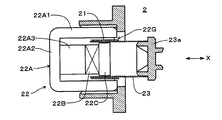
- FIG. 7 is a diagram showing an example of the drive unit, and this drive unit is applied as the drive unit 2 (2-1, 2-2, 2-3) in the first to sixth embodiments.
- the drive unit 2 includes the voice coil 21 and the magnetic circuit 22 having a magnetic gap 22G in which the voice coil 21 is disposed.
- the voice coil 21 has a cross-sectional shape that is an annular shape.
- the cross section of the voice coil 21 here is a surface extending in a direction intersecting the vibration direction (X-axis direction in the drawing) of the voice coil 21 itself.
- the voice coil 21 is composed of, for example, a linear conductive member wound around the illustrated X axis.
- the conductive member is supported by the annular voice coil support portion 23.
- the voice coil support portion 23 may be made of a known resin material.
- a connecting portion 23 a connected to the diaphragm 1 or the link mechanism 6 is attached to an end portion of the voice coil support portion 23.
- the magnetic circuit 22 includes a yoke 22A, a magnet 22B, and a plate 22C, and the yoke 22A includes an outer peripheral cylindrical portion 22A1, a bottom surface portion 22A2, and a column portion 22A3.
- the magnet 22B is magnetically joined to the column portion 22A3, and a magnetic gap 22G is formed between the outer peripheral surface of the plate 22C and the outer peripheral cylindrical portion 22A1 of the yoke 22A.
- FIG. 8B is a diagram showing another example of the drive unit, and this drive unit is applied as the drive unit 2 (2-1, 2-2, 2-3) in the first to sixth embodiments.
- the drive unit 2 includes the voice coil 21 wound around the voice coil support unit 23 and the magnetic circuit 22 having a magnetic gap 22G.
- the voice coil support portion 23 in another example of the drive portion has a plate shape.
- the magnetic circuit 22 includes a yoke 22D and a plurality of magnets 221 to 224. Magnets 221, 223 and magnets 222, 224 are provided on both sides of the magnetic gap 22G along the direction of the magnetic field.
- the magnetic gap 22G is formed in a groove shape so that the voice coil 21 can move within a specified range along a predetermined direction.
- the yoke 22D has a lower flat portion 22D1, an upper flat portion 22D2, and a column portion 22D3.
- the lower flat portion 22D1 and the upper flat portion 22D2 are arranged substantially parallel to each other with a predetermined interval, and the support column portion 22D3 is substantially at the center with respect to the lower flat portion 22D1 and the upper flat portion 22D2. It is formed so as to extend in the orthogonal direction.
- the driving unit drives the voice coil by a magnetic circuit
- the driving unit may be a piezoelectric element, a magnetostrictive element, an artificial muscle, or the like.
- the embodiments described in the above drawings can be combined with each other as long as there is no particular contradiction or problem in the purpose, configuration, or the like.
- the description content of each figure can become independent embodiment, respectively, and embodiment of this invention is not limited to one embodiment which combined each figure.
- a Sound radiation direction B Non-sound radiation direction 1-1 (1) First diaphragm 1-2 (1) Second diaphragm 1-3 (1) Third diaphragm 1-4 (1) Fourth End 1a-1 of sound radiation direction End 1a-2 of sound radiation direction End 1a-3 of sound radiation direction End 1a of sound radiation direction End 1b of sound radiation direction End 1b-1 of sound radiation direction End portion 1b-2 in the non-sound radiation direction End portion 1c-1 in the non-sound radiation direction Bending portion 12-1 Edge portion (elastic portion) 12-2 Edge part (elastic part) 12-3 Edge part (elastic part) 12-4 Edge part (elastic part) 2 Driving Unit 2-1 First Driving Unit 2-2 Second Driving Unit 2-3 Third Driving Unit 21 Voice Coil 21-1 Voice Coil 21-2 Voice Coil 21-3 Voice Coil 22 Magnetic Circuit 22- DESCRIPTION OF SYMBOLS 1 Magnetic circuit 22-2 Magnetic circuit 22-3 Magnetic circuit 23 Voice coil support part (support part) 23-1 Voice coil support (support) 23-2 Voice coil support (support) 23-3 Voice coil support (support) 31 Rear frame (
Landscapes
- Health & Medical Sciences (AREA)
- Otolaryngology (AREA)
- Physics & Mathematics (AREA)
- Engineering & Computer Science (AREA)
- Acoustics & Sound (AREA)
- Signal Processing (AREA)
- Audible-Bandwidth Dynamoelectric Transducers Other Than Pickups (AREA)
Abstract
スピーカ装置において生じる例えば振動板の面積を十分に大きくして十分な音圧を得る。複数の振動板(1-1,1-2)と、複数の振動板(1-1,1-2)を駆動する駆動部(2)と、複数の振動板(1-1,1-2)及び駆動部(2)を支持する静止部(31,32)とを備える。駆動部(2)は、ボイスコイル(21)とボイスコイル(21)を支持するボイスコイル支持部(23)を含む磁気回路(22)とを備える。ボイスコイル支持部(23)は振動板(1-1,1-2)とリンク機構(6)を介して接続する。振動板(1-1,1-2)の音放射方向(A)の端部(1a-1,1b-1)をエッジ部(12-1,12-2)を介して静止部(32)に支持する。振動板(1-1,1-2)の非音放射方向(B)の端部(1b)を静止部(31)に支持する。
Description
本発明は、スピーカ装置に関する。
従来、スピーカ装置は自動車のドアや、パソコン、テレビまたはキャビネットに取り付けられている。特に、自動車、パソコン、テレビなどにスピーカ装置を取り付ける場合、取り付け面積の制約がある。すなわち、一般的なスピーカ装置は振動板(コーン紙等)で振動された音波が放射する方向の前面は、少なくとも振動板の大きさだけの面積を専有する。
従来の一般的なスピーカ装置では、取り付け面積の制約があるため、振動板の面積を十分に大きくできず、十分な音圧を得ることができない。
本発明が解決しようとする課題には、上述した従来のスピーカ装置において生じる振動板の面積を十分に大きくできないという問題が一例として挙げられる。
請求項1に記載のスピーカ装置は、複数の振動板と、前記複数の振動板を駆動する駆動部と、前記複数の振動板及び前記駆動部を支持する静止部と、を備え、前記駆動部は前記振動板と他の部材を介して接続され、前記振動板の音放射方向の端部が弾性部を介して前記静止部に支持され、前記振動板の非音放射方向の端部が直接または他の部材を介して前記静止部に支持されていることを特徴とする。
以下、本発明の一実施形態を説明する。本発明の一実施形態に係るスピーカ装置は、複数の振動板と、複数の振動板を駆動する駆動部と、複数の振動板及び駆動部を支持する静止部と、を備えている。駆動部は、ボイスコイルと該ボイスコイルを支持する支持部を含む磁気回路とを備えている。支持部は振動板と他の部材を介して接続されている。振動板の音放射方向の端部が直接または他の部材を介して静止部に支持されている。振動板の非音放射方向の端部が直接または他の部材を介して静止部に支持されている。
本発明の一実施例を、図1乃至図8に基づいて説明する。なお、以下の各実施例において、同様な要素には同符号を付記してある。
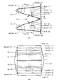
(第1実施例)本発明の第1実施例のスピーカ装置は図1に示す構造である。第1実施例のスピーカ装置が音を放射する「音放射方向」は図1(A) に示す矢印Aの方向である。「非音放射方向」は図1(A) に示す矢印Bの方向である。このスピーカ装置は、第1の振動板1-1と第2の振動板1-2からなる複数の振動板1を備えている。また、第1の振動板1-1と第2の振動板1-2をそれぞれ駆動する第1の駆動部2-1と第2の駆動部2-2を備えている。また、「静止部」としての背面フレーム31と第1の側面フレーム32-1と第2の側面フレーム32-2とを有している。
第1及び第2の駆動部2-1,2-2は、それぞれボイスコイル21-1,21-2と、磁気回路22-1,22-2とを備えている。磁気回路22-1,22-2は、ボイスコイル21-1,21-2を支持する「支持部」としてのボイスコイル支持部23-1,23-2を含んでいる。ボイスコイル支持部23-1,23-2は、振動板1-1,1-2と、「他の部材」としての接着剤4-1,4-2を介して接続されている。磁気回路22-1,22-2は、側面フレーム32-1,32-2に固定されている。
第1及び第2の振動板1-1,1-2の音放射方向Aの端部1a-1,1a-2は、「弾性部」としての、エッジ部12-1,12-2を介して「静止部」としての側面フレーム32-1,32-2にそれぞれ支持されている。なお、エッジ部が図1のような形状に限らず、振動板1-1、1-2をフレームに支持するような構造であればよい。振動板1の非音放射方向Bの端部1bは固定バー5と背面フレーム31とに挟まれている。これにより、非音放射方向Bの端部1bは「静止部」としての背面フレーム31に支持されている。第1及び第2の振動板1-1,1-2は一枚の板状部材を端部1bの箇所で折り曲げて形成されたものであり、第1の振動板1-1と第2の振動板1-2とが略同じ形状になっている。また、音放射方向Aの端部1a-1,1a-2における第1の振動板1-1と第2の振動板1-2の距離は、非音放射方向Bの端部1bにおける第1の振動板1-1と第2の振動板1-2の距離よりも大きくなっている。
以上の構成により、第1及び第2の磁気回路22-1,22-2に同じ音響信号が供給される。これにより、ボイスコイル支持部23-1,23-2が直線運動して振動し、振動板1-1,1-2が矢印Cのように振動する。振動板1-1,1-2の音放射方向の端部1a-1,1a-2がそれぞれ近接離間するように振動する。振動板1-1,1-2の振動により音響信号に応じた音が、音放射方向Aの方向に放射される。
第1及び第2の振動板1-1,1-2の非音放射方向の端部1bにおける会合角度は60°より小さくなっている。したがって、第1及び第2の振動板1-1,1-2の音放射方向の端部1a-1,1a-2の間隔は、第1及び第2の振動板1-1,1-2の各長さ(図1(A) の断面の長さ)より小さくなっている。これにより、表面での占有スペースが限られた場所に設置するのに適している。取り付け面積に制約があっても、振動板1-1,1-2の面積を十分に大きくすることができ、十分な音圧を得ることができる。
(第2実施例)本発明の第2実施例のスピーカ装置は図2に示す構造である。第2実施例のスピーカ装置が音を放射する「音放射方向」は図2(A) に示す矢印Aの方向である。「非音放射方向」は図2(A) に示す矢印Bの方向である。このスピーカ装置は、第1の振動板1-1と第2の振動板1-2からなる複数の振動板1を備えている。また、第1の振動板1-1と第2の振動板1-2とを駆動する一つの駆動部2を備えている。また、「静止部」としての背面フレーム31と第1の側面フレーム32-1と第2の側面フレーム32-2とを有している。
駆動部2は、ボイスコイル21と、磁気回路22とを備えている。磁気回路22は、ボイスコイル21を支持する「支持部」としてのボイスコイル支持部23を含んでいる。ボイスコイル支持部23は、振動板1-1,1-2と、「他の部材」としてのリンク機構6を介して接続されている。磁気回路22は、図示しない部材により側面フレーム32-1,32-2に固定されている。
第1及び第2の振動板1-1,1-2の音放射方向Aの端部1a-1,1a-2は、「弾性部」としての、エッジ部12-1,12-2を介して「静止部」としての側面フレーム32-1,32-2にそれぞれ支持されている。振動板1の非音放射方向Bの端部1bは固定バー5と背面フレーム31とに挟まれている。これにより、非音放射方向Bの端部1bは「静止部」としての背面フレーム31に支持されている。第1及び第2の振動板1-1,1-2は一枚の部材を端部1bの箇所で折り曲げて形成されたものであり、第1の振動板1-1と第2の振動板1-2とが略同じ形状になっている。また、音放射方向Aの端部1a-1,1a-2における第1の振動板1-1と第2の振動板1-2の距離は、非音放射方向Bの端部1bにおける第1の振動板1-1と第2の振動板1-2の距離よりも大きくなっている。
リンク機構6は、第1の振動板1-1に対応するリンク部材61と、第2の振動板1-2に対応するリンク部材62とを含んでいる。リンク部材61,62は第1及び第2の振動板1-1,1-2に接続された関節部6a,6bを有している。また、リンク部材61,62は関節部6cにより駆動部2のボイスコイル支持部23に接続されている。関節部6a,6b,6cは、それぞれリンク部材61,62を他の部分に対して角度変更自在に支持又は連結する部分である。
以上の構成により、磁気回路22に音響信号が供給され、ボイスコイル支持部23が直線運動して振動する。リンク機構6のリンク部材61,62はボイスコイル支持部23の振動を振動板1-1,1-2に伝達する。振動板1-1,1-2は矢印Cのように振動する。振動板1-1,1-2の音放射方向の端部1a-1,1a-2がそれぞれ近接離間するように振動する。振動板1-1,1-2の振動により音響信号に応じた音が、音放射方向Aの方向に放射される。
第1及び第2の振動板1-1,1-2の非音放射方向の端部1bにおける会合角度は60°より小さくなっている。したがって、第1及び第2の振動板1-1,1-2の音放射方向の端部1a-1,1a-2の間隔は、第1及び第2の振動板1-1,1-2の各長さ(図1(A) の断面の長さ)より小さくなっている。これにより、表面での占有スペースが限られた場所に設置するのに適している。取り付け面積に制約があっても、振動板1-1,1-2の面積を十分に大きくすることができ、十分な音圧を得ることができる。
第2実施例では、第1及び第2の振動板1-1,1-2を振動させるために、一つの駆動部2だけでよい。したがって、コストを低減できる。また、音響信号を供給する配線等の構成も簡単になる。
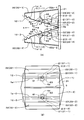
(第3実施例)本発明の第3実施例のスピーカ装置は図3に示す構造である。第3実施例のスピーカ装置が音を放射する「音放射方向」は図3(A) に示す矢印Aの方向である。「非音放射方向」は図3(A) に示す矢印Bの方向である。このスピーカ装置は、第1の振動板1-1と第2の振動板1-2からなる複数の振動板1を備えている。また、第1の振動板1-1と第2の振動板1-2をそれぞれ駆動する第1の駆動部2-1と第2の駆動部2-2を備えている。また、「静止部」としての背面フレーム31と第1の側面フレーム32-1と第2の側面フレーム32-2とを有している。
第1及び第2の駆動部2-1,2-2は、それぞれボイスコイル21-1,21-2と、磁気回路22-1,22-2とを備えている。磁気回路22-1,22-2は、ボイスコイル21-1,21-2を支持する「支持部」としてのボイスコイル支持部23-1,23-2を含んでいる。ボイスコイル支持部23-1は、振動板1-1と「他の部材」としての第1のリンク機構6-1を介して接続されている。ボイスコイル支持部23-2は、振動板1-2と「他の部材」としての第2のリンク機構6-2を介して接続されている。磁気回路22-1,22-2は背面フレーム31に固定されている。
第1及び第2の振動板1-1,1-2の音放射方向Aの端部1a-1,1a-2は、「弾性部」としての、エッジ部12-1,12-2を介して「静止部」としての側面フレーム32-1,32-2にそれぞれ支持されている。振動板1の非音放射方向Bの端部1bは固定バー5と背面フレーム31とに挟まれている。これにより、非音放射方向Bの端部1bは「静止部」としての背面フレーム31に支持されている。第1及び第2の振動板1-1,1-2は一枚の部材を端部1bの箇所で折り曲げて形成されたものであり、第1の振動板1-1と第2の振動板1-2とが略同じ形状になっている。
第1及び第2のリンク機構6-1,6-2は鏡映対称な同じ構造であり、振動板1-1(1-2)とボイスコイル支持部23-1(23-2)との間に位置するリンク部材63と、リンク部材63の中間位置と側面フレーム32-1(32-2)の突起32a-1(32a-2)との間に位置するリンク部材64とを含んでいる。リンク部材63は振動板1-1(1-2)に接続された関節部6dを有している。また、リンク部材63は関節部6fにより駆動部2-1(2-2)のボイスコイル支持部23-1(23-2)に接続されている。また、リンク部材64は、関節部6eにより突起32a-1(32a-2)に接続されるとともに、関節部6gによりリンク部材63の中間位置に接続されている。関節部6d,6e,6f,6gは、それぞれリンク部材63,64を他の部分に対して角度変更自在に支持又は連結する部分である。
以上の構成により、第1及び第2の磁気回路22-1,22-2に同じ音響信号が供給される。これにより、ボイスコイル支持部23-1,23-2が直線運動して振動する。リンク機構6-1,6-2のリンク部材63はボイスコイル支持部23-1,23-2の振動を振動板1-1,1-2に伝達する。振動板1-1,1-2は矢印Cのように振動する。振動板1-1,1-2の音放射方向の端部1a-1,1a-2がそれぞれ近接離間するように振動する。振動板1-1,1-2の振動により音響信号に応じた音が、音放射方向Aの方向に放射される。
第1及び第2の振動板1-1,1-2の非音放射方向の端部1bにおける会合角度は60°より小さくなっている。したがって、第1及び第2の振動板1-1,1-2の音放射方向の端部1a-1,1a-2の間隔は、第1及び第2の振動板1-1,1-2の各長さ(図1(A) の断面の長さ)より小さくなっている。これにより、表面での占有スペースが限られた場所に設置するのに適している。取り付け面積に制約があっても、振動板1-1,1-2の面積を十分に大きくすることができ、十分な音圧を得ることができる。
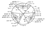
(第4実施例)本発明の第4実施例のスピーカ装置は図4に示す構造である。第4実施例のスピーカ装置が音を放射する「音放射方向」は図4に向かって手前側である。「非音放射方向」は図4に向かって奥側である。このスピーカ装置は、第1の振動板1-1と第2の振動板1-2と第3の振動板1-3からなる複数の振動板1を備えている。また、第1の振動板1-1と第2の振動板1-2と第3の振動板1-3をそれぞれ駆動する第1の駆動部2-1と第2の駆動部2-2と第3の駆動部2-3を備えている。また、「静止部」としての背面フレーム31と円筒状の側面フレーム32とを有している。
第1乃至第3の駆動部2-1,2-2,2-3は、それぞれボイスコイル21-1,21-2,21-3と、磁気回路22-1,22-2,22-3とを備えている。磁気回路22-1,22-2,22-3は、ボイスコイル21-1,21-2,21-3を支持する「支持部」としてのボイスコイル支持部23-1,23-2,23-3を含んでいる。ボイスコイル支持部23-1は、振動板1-1と「他の部材」としての第1のリンク機構6-1を介して接続されている。ボイスコイル支持部23-2は、振動板1-2と「他の部材」としての第2のリンク機構6-2を介して接続されている。ボイスコイル支持部23-3は、振動板1-3と「他の部材」としての第3のリンク機構6-3を介して接続されている。磁気回路22-1,22-2,22-3は背面フレーム31に固定されている。
第1乃至第3の振動板1-1,1-2,1-3の音放射方向の端部1a-1,1a-2,1a-3は、「弾性部」としての、エッジ部12-1,12-2,12-3を介して「静止部」としての側面フレーム32にそれぞれ支持されている。振動板1-1,1-2,1-3の非音放射方向の端部1bは図示しない部材により「静止部」としての背面フレーム31に支持されている。
第1乃至第3のリンク機構6-1,6-2,6-3は第3実施例(図3)のリンク機構6-1,6-2と同じ構造である。なお、図4ではリンク機構6-1,6-2,6-3のリンク部材63、関節部6d,6fのみ図示してあるが、第3実施例と同じリンク部材64及び関節部6e,6gも備えている。そして、このリンク機構6-1,6-2,6-3は、第3実施形態と同様に、それぞれ振動板1-1(1-2,1-3)とボイスコイル支持部23-1(23-2,23-3)とを接続している。
以上の構成により、第1乃至第3の磁気回路22-1,22-2,22-3に同じ音響信号が供給される。これにより、ボイスコイル支持部23-1,23-2,23-3が直線運動して振動する。リンク機構6-1,6-2,6-3のリンク部材63はボイスコイル支持部23-1,23-2,23-3の振動を振動板1-1,1-2,1-3に伝達する。振動板1-1,1-2,1-3は第3実施例の矢印Cと同様に内外に振動する。振動板1-1,1-2,1-3の音放射方向の端部1a-1,1a-2,1a-3がそれぞれ近接離間するように振動する。振動板1-1,1-2,1-3の振動により音響信号に応じた音が、音放射方向の方向に放射される。
第1乃至第3の振動板1-1,1-2,1-3の非音放射方向の端部1bにおける会合角度は60°より小さくなっている。したがって、第1乃至第3の振動板1-1,1-2,1-3の音放射方向の端部1a-1,1a-2,1a-3の相互の間隔は、第1乃至第3の振動板1-1,1-2,1-3の各長さより小さくなっている。これにより、表面での占有スペースが限られた場所に設置するのに適している。取り付け面積に制約があっても、振動板1-1,1-2,1-3の面積を十分に大きくすることができ、十分な音圧を得ることができる。
(第5実施例)本発明の第5実施例のスピーカ装置は図5に示す構造である。第5実施例のスピーカ装置が音を放射する「音放射方向」は図5に向かって手前側である。「非音放射方向」は図5に向かって奥側である。このスピーカ装置は、第1の振動板1-1と第2の振動板1-2と第3の振動板1-3と第4の振動板1-4からなる複数の振動板1を備えている。また、第1の振動板1-1と第2の振動板1-2と第3の振動板1-3と第4の振動板1-4をそれぞれ駆動する一つの駆動部2を備えている。また、「静止部」としての背面フレーム31と円筒状の側面フレーム32とを有している。
駆動部2は、ボイスコイル21と、磁気回路22とを備えている。磁気回路22は、ボイスコイル21を支持する「支持部」としてのボイスコイル支持部23を含んでいる。ボイスコイル支持部23は、振動板1-1,1-2,1-3,1-4と、「他の部材」としてのリンク機構6を介して接続されている。磁気回路22は、図示しない部材により側面フレーム32に固定されている。
第1乃至第4の振動板1-1,1-2,1-3,1-4の音放射方向の端部1a-1,1a-2,1a-3,1a-4は、「弾性部」としての、エッジ部12-1,12-2,12-3,12-4を介して「静止部」としての側面フレーム32にそれぞれ支持されている。振動板-1,1-2,1-3,1-4の非音放射方向の図示しない端部は図示しない部材により「静止部」としての背面フレーム31に支持されている。
リンク機構6は、第2実施例(図2)のリンク機構6と同様な構成を二組設けたものである。すなわち、リンク部材61-1,62-3の対と、リンク部材61-2,62-4の対を、直角に交差するように二組設けた、十字形状をしている。また、第2実施例と同様に、各リンク部材61-1,61-2,62-3,62-4は関節部6a,6b,6cを有している。
一方の組のリンク部材61-1,62-3は第1及び第3の振動板1-1,1-3に接続された関節部6a,6bを有している。また、リンク部材61-1,62-3は関節部6c,6cにより駆動部2のボイスコイル支持部23に接続されている。他方の組のリンク部材61-2,62-4は第2及び第4の振動板1-2,1-4に接続された関節部6a,6bを有している。また、リンク部材61-2,62-4は関節部6c,6cにより駆動部2のボイスコイル支持部23に接続されている。関節部6a,6b,6cは、それぞれリンク部材61-1,61-2,62-3,62-4を他の部分に対して角度変更自在に支持又は連結する部分である。
以上の構成により、磁気回路22に音響信号が供給され、ボイスコイル支持部23が直線運動して振動する。リンク機構6のリンク部材61-1,61-2,62-3,62-4はボイスコイル支持部23の振動を振動板1-1,1-2,1-3,1-4に伝達する。振動板1-1,1-2,1-3,1-4は第2実施例の矢印Cと同様に内外に振動する。振動板1-1,1-2,1-3,1-4の音放射方向の端部1a-1,1a-2,1a-3,1a-4がそれぞれ近接離間するように振動する。振動板1-1,1-2,1-3,1-4の振動により音響信号に応じた音が、音放射方向の方向に放射される。
第1乃至第4の振動板1-1,1-2,1-3,1-4の非音放射方向の端部1bにおける会合角度は60°より小さくなっている。したがって、第1乃至第4の振動板1-1,1-2,1-3,1-4の音放射方向の端部1a-1,1a-2,1a-3,1a-4の相互の間隔は、第1乃至第4の振動板1-1,1-2,1-3,1-4の各長さより小さくなっている。これにより、表面での占有スペースが限られた場所に設置するのに適している。取り付け面積に制約があっても、振動板1-1,1-2,1-3,1-4の面積を十分に大きくすることができ、十分な音圧を得ることができる。
第5実施例では、第1及び第4の振動板1-1,1-2,1-3,1-4を振動させるために、一つの駆動部2だけでよい。したがって、コストが低減できる。また、音響信号を供給する配線等の構成も簡単になる。
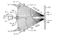
(第6実施例)本発明の第6実施例のスピーカ装置は図6に示す構造である。第6実施例のスピーカ装置が音を放射する「音放射方向」は図6に示す矢印Aの方向である。「非音放射方向」は図6に示す矢印Bの方向である。このスピーカ装置は、第1の振動板1-1と第2の振動板1-2からなる複数の振動板1を備えている。また、第1の振動板1-1と第2の振動板1-2とを駆動する一つの駆動部2を備えている。また、「静止部」としての背面フレーム31と図示しない側面フレームとを有している。
駆動部2は、ボイスコイル21と、磁気回路22とを備えている。磁気回路22は、ボイスコイル21を支持する「支持部」としてのボイスコイル支持部23を含んでいる。ボイスコイル支持部23は、振動板1-1,1-2と、「他の部材」としてのリンク機構6を介して接続されている。磁気回路22は、図示しない部材により側面フレーム32-1,32-2に固定されている。
第1及び第2の振動板1-1,1-2の音放射方向Aの内側の端部1d-1,1d-2は、「静止部」としての固定部33により図示しない側面フレームにそれぞれ支持されている。振動板1-1,1-2の非音放射方向Bの端部1b-1,1b-2は、固定部34により背面フレーム31に支持されている。第1及び第2の振動板1-1,1-2は、それぞれ非音放射方向Bの端部1b-1,1b-2から音放射方向Aの端部1a-1,1a-2,1d-1,1d-2に向かって複数の折曲部分1c-1,1c-2が形成されている。なお、この例では外側の端部1a-1(1a-2)から内側の端部1d-1(1d-2)までの複数の折曲部分1c-1(1c-2)が形成されている部分が「弾性部」に相当し、音放射方向Aの端部1a-1,1a-2は、弾性部により静止部に支持されている。
リンク機構6は、第1の振動板1-1に対応するリンク部材61と、第2の振動板1-2に対応するリンク部材62と、駆動部2に連結するリンク部材65を含んでいる。リンク部材61,62は第1及び第2の振動板1-1,1-2に接続された関節部6a,6bを有している。また、リンク部材61,62は関節部6cによりリンク部材65に接続されている。リンク部材65は駆動部2のボイスコイル支持部23に接続されている。関節部6a,6b,6cは、それぞれリンク部材61,62を他の部分に対して角度変更自在に支持又は連結する部分である。
以上の構成により、磁気回路22に音響信号が供給され、ボイスコイル支持部23が直線運動して振動する。リンク機構6のリンク部材61,62,65はボイスコイル支持部23の振動を振動板1-1,1-2に伝達する。振動板1-1,1-2は矢印Cのように振動する。振動板1-1,1-2の音放射方向の外側の端部1a-1,1a-2がそれぞれ近接離間するように振動する。また、振動板1-1,1-2は複数の折曲部分1c-1,1c-2を有しているので、伸縮して振動する。これにより音響信号に応じた音が音放射方向Aの方向に放射される。
第1及び第2の振動板1-1,1-2は折曲部分1c-1,1c-2を有する縦方向にも幅の広いものとなっている。外側の端部1a-1,1d-2の間隔は、第1及び第2の振動板1-1,1-2の各長さより小さくなっている。これにより、表面での占有スペースが限られた場所に設置するのに適している。取り付け面積に制約があっても、振動板1-1,1-2の面積を十分に大きくすることができ、十分な音圧を得ることができる。
第6実施例では、第1及び第2の振動板1-1,1-2を振動させるために、一つの駆動部2だけでよい。したがって、コストが低減できる。また、音響信号を供給する配線等の構成も簡単になる。
図7は駆動部の一例を示す図であり、この駆動部は第1乃至第6実施例における駆動部2(2-1,2-2,2-3)として適用される。この駆動部2は、前記ボイスコイル21とボイスコイル21が配置される磁気ギャップ22Gを有する前記磁気回路22とを備えている。ボイスコイル21は、環状の形態である断面形状を有する。なお、ここでのボイスコイル21の断面は、ボイスコイル21自身の振動方向(図示X軸方向)に交差する方向に延在する面である。
ボイスコイル21は、例えば、図示のX軸周りに巻き回された線状の導電部材で構成されている。図示の例では、導電部材が環状の前記ボイスコイル支持部23に支持されている。このボイスコイル支持部23は、公知の樹脂材料で構成されて構わない。ボイスコイル支持部23の端部には前記振動板1あるいはリンク機構6に接続される結合部23aが取り付けられている。
磁気回路22は、ヨーク22Aと磁石22Bとプレート22Cを備えており、ヨーク22Aは外周筒部22A1と底面部22A2と柱部22A3を備える。柱部22A3に磁石22Bが磁気的に接合し、プレート22Cの外周面とヨーク22Aの外周筒部22A1との間に磁気ギャップ22Gが形成される。そして、図示しない引出線を介してボイスコイル21に音声信号が入力されると、ボイスコイル21を流れる音声電流が磁気ギャップ22Gの磁束を横切ることでローレンツ力が生じ、ボイスコイル21及びボイスコイル支持部23がX軸方向に沿って振動する。これが前記振動板1(1-1,1-2,1-3,1-4)を振動させる駆動力になる。
図8 は駆動部の他の一例を示す図であり、この駆動部は第1乃至第6実施例における駆動部2(2-1,2-2,2-3)として適用される。この駆動部2は、前記ボイスコイル支持部23に巻回された前記ボイスコイル21と、磁気ギャップ22Gを有する前記磁気回路22とを備えている。この他の一例の駆動部におけるボイスコイル支持部23は板形状である。磁気回路22は、ヨーク22Dおよび複数の磁石221~224を有する。磁石221,223、磁石222,224が、磁気ギャップ22Gの磁場の方向に沿った両側に設けられている。例えば磁気ギャップ22Gは、ボイスコイル21が所定方向に沿って規定範囲内で移動することができるように溝形状に形成されている。
ヨーク22Dは、下側平坦部22D1、上側平坦部22D2、および支柱部22D3を有する。下側平坦部22D1、上側平坦部22D2は、規定間隔をあけて略平行に配置されており、中央部には、支柱部22D3が、下側平坦部22D1、および上側平坦部22D2に対して略直交する方向へ延在するように形成されている。
そして、磁場中のボイスコイル21に図示しない引出線を介して音声信号(電流)が流れると、フレミング左手の法則により、磁場の方向および電流の方向それぞれに直交する方向に沿って、ローレンツ力が生じる。すなわち、X軸方向に沿って、ボイスコイル21にローレンツ力が生じ、ボイスコイル21及びボイスコイル支持部23がX軸方向に沿って振動する。これが前記振動板1(1-1,1-2,1-3,1-4)を振動させる駆動力になる。
以上、本発明の実施の形態について図面を参照して詳述してきたが、具体的な構成はこれらの実施の形態に限られるものではなく、本発明の要旨を逸脱しない範囲の設計の変更等があっても本発明に含まれる。駆動部は磁気回路によってボイスコイルを駆動する構成のみを開示したが、駆動部としては他に圧電素子、磁歪素子、人工筋肉等でもよい。上述の各図で示した実施の形態は、その目的及び構成等に特に矛盾や問題がない限り、互いの記載内容を組み合わせることが可能である。また、各図の記載内容はそれぞれ独立した実施形態になり得るものであり、本発明の実施形態は各図を組み合わせた一つの実施形態に限定されるものではない。
A 音放射方向
B 非音放射方向
1-1(1) 第1の振動板
1-2(1) 第2の振動板
1-3(1) 第3の振動板
1-4(1) 第4の振動板
1a-1 音放射方向の端部
1a-2 音放射方向の端部
1a-3 音放射方向の端部
1a-4 音放射方向の端部
1b 非音放射方向の端部
1b-1 非音放射方向の端部
1b-2 非音放射方向の端部
1c-1 折曲部分
12-1 エッジ部(弾性部)
12-2 エッジ部(弾性部)
12-3 エッジ部(弾性部)
12-4 エッジ部(弾性部)
2 駆動部
2-1 第1の駆動部
2-2 第2の駆動部
2-3 第3の駆動部
21 ボイスコイル
21-1 ボイスコイル
21-2 ボイスコイル
21-3 ボイスコイル
22 磁気回路
22-1 磁気回路
22-2 磁気回路
22-3 磁気回路
23 ボイスコイル支持部(支持部)
23-1 ボイスコイル支持部(支持部)
23-2 ボイスコイル支持部(支持部)
23-3 ボイスコイル支持部(支持部)
31 背面フレーム(静止部)
32-1 第1の側面フレーム(静止部)
32-2 第2の側面フレーム(静止部)
33 固定部(静止部)
4-1 接着剤(他の部材)
4-2 接着剤(他の部材)
6 リンク機構(他の部材)
6-1 リンク機構(他の部材)
6-2 リンク機構(他の部材)
6-3 リンク機構(他の部材)
61 リンク部材
62 リンク部材
63 リンク部材
64 リンク部材
65 リンク部材
6a 関節部
6b 関節部
6c 関節部
6d 関節部
6f 関節部
6e 関節部
6g 関節部
22G 磁気ギャップ
22A ヨーク
22B 磁石
22C プレート
22D ヨーク
221 磁石
222 磁石
223 磁石
224 磁石
B 非音放射方向
1-1(1) 第1の振動板
1-2(1) 第2の振動板
1-3(1) 第3の振動板
1-4(1) 第4の振動板
1a-1 音放射方向の端部
1a-2 音放射方向の端部
1a-3 音放射方向の端部
1a-4 音放射方向の端部
1b 非音放射方向の端部
1b-1 非音放射方向の端部
1b-2 非音放射方向の端部
1c-1 折曲部分
12-1 エッジ部(弾性部)
12-2 エッジ部(弾性部)
12-3 エッジ部(弾性部)
12-4 エッジ部(弾性部)
2 駆動部
2-1 第1の駆動部
2-2 第2の駆動部
2-3 第3の駆動部
21 ボイスコイル
21-1 ボイスコイル
21-2 ボイスコイル
21-3 ボイスコイル
22 磁気回路
22-1 磁気回路
22-2 磁気回路
22-3 磁気回路
23 ボイスコイル支持部(支持部)
23-1 ボイスコイル支持部(支持部)
23-2 ボイスコイル支持部(支持部)
23-3 ボイスコイル支持部(支持部)
31 背面フレーム(静止部)
32-1 第1の側面フレーム(静止部)
32-2 第2の側面フレーム(静止部)
33 固定部(静止部)
4-1 接着剤(他の部材)
4-2 接着剤(他の部材)
6 リンク機構(他の部材)
6-1 リンク機構(他の部材)
6-2 リンク機構(他の部材)
6-3 リンク機構(他の部材)
61 リンク部材
62 リンク部材
63 リンク部材
64 リンク部材
65 リンク部材
6a 関節部
6b 関節部
6c 関節部
6d 関節部
6f 関節部
6e 関節部
6g 関節部
22G 磁気ギャップ
22A ヨーク
22B 磁石
22C プレート
22D ヨーク
221 磁石
222 磁石
223 磁石
224 磁石
Claims (11)
- 複数の振動板と、
前記複数の振動板を駆動する駆動部と、
前記複数の振動板及び前記駆動部を支持する静止部と、
を備え、
前記駆動部は前記振動板と他の部材を介して接続され、
前記振動板の音放射方向の端部が弾性部を介して前記静止部に支持され、
前記振動板の非音放射方向の端部が直接または他の部材を介して前記静止部に支持されていることを特徴とするスピーカ装置。 - 前記複数の振動板は、
音放射方向の端部がそれぞれ近接離間するように振動することを特徴とする請求項1に記載のスピーカ装置。 - 前記駆動部はボイスコイルを備え、
該ボイスコイルを支持する支持部を備えることを特徴とする請求項2に記載のスピーカ装置。 - 前記支持部と前記振動板を接続する他の部材は関節部を含むことを特徴とする請求項2に記載のスピーカ装置。
- 前記支持部と前記振動板を接続する他の部材は前記関節部を有するリンク部材を含むことを特徴とする請求項4に記載のスピーカ装置。
- 前記複数の振動板は、第1及び第2の2つの振動板からなることを特徴とする請求項2に記載のスピーカ装置。
- 前記第1の振動板と前記第2の振動板とが、一つの板状部材をその中心で折り曲げることにより略同じ形状になるように形成されているこことを特徴とする請求項6に記載のスピーカ装置。
- 前記音放射方向の端部における前記第1の振動板と前記第2の振動板との距離は、
前記非音放射方向の端部における前記第1の振動板と前記第2の振動板の距離よりも大きいことを特徴とする請求項6に記載のスピーカ装置。 - 前記第1の振動板と前記第2の振動板には、非音放射方向の端部から音放射方向の端部に向かって複数の折曲部分が形成されていることを特徴とする請求項6に記載のスピーカ装置。
- 前記駆動部は、
磁石と、
前記ボイスコイルが位置する磁気ギャップと、
を備えることを特徴とする請求項1に記載のスピーカ装置。 - 前記磁気ギャップ内に位置している前記ボイスコイル支持部は板形状であることを特徴とする請求項10に記載のスピーカ装置。
Priority Applications (1)
| Application Number | Priority Date | Filing Date | Title |
|---|---|---|---|
| PCT/JP2012/082345 WO2014091597A1 (ja) | 2012-12-13 | 2012-12-13 | スピーカ装置 |
Applications Claiming Priority (1)
| Application Number | Priority Date | Filing Date | Title |
|---|---|---|---|
| PCT/JP2012/082345 WO2014091597A1 (ja) | 2012-12-13 | 2012-12-13 | スピーカ装置 |
Publications (1)
| Publication Number | Publication Date |
|---|---|
| WO2014091597A1 true WO2014091597A1 (ja) | 2014-06-19 |
Family
ID=50933918
Family Applications (1)
| Application Number | Title | Priority Date | Filing Date |
|---|---|---|---|
| PCT/JP2012/082345 Ceased WO2014091597A1 (ja) | 2012-12-13 | 2012-12-13 | スピーカ装置 |
Country Status (1)
| Country | Link |
|---|---|
| WO (1) | WO2014091597A1 (ja) |
Citations (4)
| Publication number | Priority date | Publication date | Assignee | Title |
|---|---|---|---|---|
| JPH03262300A (ja) * | 1990-03-12 | 1991-11-21 | Audio Technica Corp | 電気音響変換器 |
| JP2005175859A (ja) * | 2003-12-11 | 2005-06-30 | Minebea Co Ltd | スピーカ用振動板の駆動体および該駆動体を使用したスピーカ |
| JP2006060330A (ja) * | 2004-08-17 | 2006-03-02 | Toa Corp | ステレオ再生装置 |
| WO2010106685A1 (ja) * | 2009-03-19 | 2010-09-23 | パイオニア株式会社 | スピーカ装置 |
-
2012
- 2012-12-13 WO PCT/JP2012/082345 patent/WO2014091597A1/ja not_active Ceased
Patent Citations (4)
| Publication number | Priority date | Publication date | Assignee | Title |
|---|---|---|---|---|
| JPH03262300A (ja) * | 1990-03-12 | 1991-11-21 | Audio Technica Corp | 電気音響変換器 |
| JP2005175859A (ja) * | 2003-12-11 | 2005-06-30 | Minebea Co Ltd | スピーカ用振動板の駆動体および該駆動体を使用したスピーカ |
| JP2006060330A (ja) * | 2004-08-17 | 2006-03-02 | Toa Corp | ステレオ再生装置 |
| WO2010106685A1 (ja) * | 2009-03-19 | 2010-09-23 | パイオニア株式会社 | スピーカ装置 |
Similar Documents
| Publication | Publication Date | Title |
|---|---|---|
| JP4457165B2 (ja) | スピーカ装置 | |
| JP6082846B2 (ja) | ダブルダイアフラム型スピーカーモジュール | |
| JP3972306B2 (ja) | スピーカ用振動板およびこの振動板を使用したスピーカ | |
| KR101061550B1 (ko) | 장방형 서스펜션 및 이를 채용한 스피커 모듈 | |
| CN103650531B (zh) | 具有力抵消配置的扬声器 | |
| JP6425101B2 (ja) | 感覚信号出力装置 | |
| RU2011142163A (ru) | Устройство громкоговорителя | |
| KR102750853B1 (ko) | 분산 트랜스듀서 서스펜션 콘(dtsc) | |
| US8958596B2 (en) | Vibration system and speaker using the same | |
| CN111373765A (zh) | 低轮廓扬声器装置 | |
| JP6188417B2 (ja) | ハイブリッドスピーカ | |
| WO2014091598A1 (ja) | スピーカ装置 | |
| KR20160108518A (ko) | 다중 진동막 스피커 | |
| JP6052669B2 (ja) | スピーカとそのスピーカを用いた電子機器 | |
| JP2009267779A (ja) | 電磁型電気音響変換器 | |
| JP2012034184A (ja) | スピーカ装置 | |
| WO2014091597A1 (ja) | スピーカ装置 | |
| JP4687400B2 (ja) | スピーカ装置 | |
| JP2005175859A (ja) | スピーカ用振動板の駆動体および該駆動体を使用したスピーカ | |
| JP7410452B2 (ja) | 音響装置 | |
| CN103329572B (zh) | 扬声器及具备扬声器的电子设备 | |
| JP2023108700A (ja) | パネルスピーカ | |
| JP2015109578A (ja) | 電気音響変換器 | |
| JP2006020135A (ja) | 振動板駆動ユニット及びこのユニットを用いた薄型スピーカ | |
| KR101100122B1 (ko) | 스피커 |
Legal Events
| Date | Code | Title | Description |
|---|---|---|---|
| 121 | Ep: the epo has been informed by wipo that ep was designated in this application |
Ref document number: 12889861 Country of ref document: EP Kind code of ref document: A1 |
|
| NENP | Non-entry into the national phase |
Ref country code: DE |
|
| 122 | Ep: pct application non-entry in european phase |
Ref document number: 12889861 Country of ref document: EP Kind code of ref document: A1 |
|
| NENP | Non-entry into the national phase |
Ref country code: JP |