WO2014087803A1 - 媒体受渡装置及び媒体処理装置 - Google Patents
媒体受渡装置及び媒体処理装置 Download PDFInfo
- Publication number
- WO2014087803A1 WO2014087803A1 PCT/JP2013/080318 JP2013080318W WO2014087803A1 WO 2014087803 A1 WO2014087803 A1 WO 2014087803A1 JP 2013080318 W JP2013080318 W JP 2013080318W WO 2014087803 A1 WO2014087803 A1 WO 2014087803A1
- Authority
- WO
- WIPO (PCT)
- Prior art keywords
- shutter
- link
- medium
- closed state
- lid
- Prior art date
- Legal status (The legal status is an assumption and is not a legal conclusion. Google has not performed a legal analysis and makes no representation as to the accuracy of the status listed.)
- Ceased
Links
Images









Classifications
-
- B—PERFORMING OPERATIONS; TRANSPORTING
- B65—CONVEYING; PACKING; STORING; HANDLING THIN OR FILAMENTARY MATERIAL
- B65H—HANDLING THIN OR FILAMENTARY MATERIAL, e.g. SHEETS, WEBS, CABLES
- B65H31/00—Pile receivers
- B65H31/24—Pile receivers multiple or compartmented, e.d. for alternate, programmed, or selective filling
-
- G—PHYSICS
- G07—CHECKING-DEVICES
- G07D—HANDLING OF COINS OR VALUABLE PAPERS, e.g. TESTING, SORTING BY DENOMINATIONS, COUNTING, DISPENSING, CHANGING OR DEPOSITING
- G07D9/00—Counting coins; Handling of coins not provided for in the other groups of this subclass
-
- G—PHYSICS
- G07—CHECKING-DEVICES
- G07F—COIN-FREED OR LIKE APPARATUS
- G07F19/00—Complete banking systems; Coded card-freed arrangements adapted for dispensing or receiving monies or the like and posting such transactions to existing accounts, e.g. automatic teller machines
- G07F19/20—Automatic teller machines [ATMs]
- G07F19/201—Accessories of ATMs
-
- B—PERFORMING OPERATIONS; TRANSPORTING
- B65—CONVEYING; PACKING; STORING; HANDLING THIN OR FILAMENTARY MATERIAL
- B65H—HANDLING THIN OR FILAMENTARY MATERIAL, e.g. SHEETS, WEBS, CABLES
- B65H29/00—Delivering or advancing articles from machines; Advancing articles to or into piles
- B65H29/20—Delivering or advancing articles from machines; Advancing articles to or into piles by contact with rotating friction members, e.g. rollers, brushes, or cylinders
- B65H29/22—Delivering or advancing articles from machines; Advancing articles to or into piles by contact with rotating friction members, e.g. rollers, brushes, or cylinders and introducing into a pile
-
- B—PERFORMING OPERATIONS; TRANSPORTING
- B65—CONVEYING; PACKING; STORING; HANDLING THIN OR FILAMENTARY MATERIAL
- B65H—HANDLING THIN OR FILAMENTARY MATERIAL, e.g. SHEETS, WEBS, CABLES
- B65H29/00—Delivering or advancing articles from machines; Advancing articles to or into piles
- B65H29/58—Article switches or diverters
-
- B—PERFORMING OPERATIONS; TRANSPORTING
- B65—CONVEYING; PACKING; STORING; HANDLING THIN OR FILAMENTARY MATERIAL
- B65H—HANDLING THIN OR FILAMENTARY MATERIAL, e.g. SHEETS, WEBS, CABLES
- B65H31/00—Pile receivers
- B65H31/04—Pile receivers with movable end support arranged to recede as pile accumulates
- B65H31/06—Pile receivers with movable end support arranged to recede as pile accumulates the articles being piled on edge
-
- B—PERFORMING OPERATIONS; TRANSPORTING
- B65—CONVEYING; PACKING; STORING; HANDLING THIN OR FILAMENTARY MATERIAL
- B65H—HANDLING THIN OR FILAMENTARY MATERIAL, e.g. SHEETS, WEBS, CABLES
- B65H31/00—Pile receivers
- B65H31/04—Pile receivers with movable end support arranged to recede as pile accumulates
- B65H31/08—Pile receivers with movable end support arranged to recede as pile accumulates the articles being piled one above another
- B65H31/10—Pile receivers with movable end support arranged to recede as pile accumulates the articles being piled one above another and applied at the top of the pile
-
- G—PHYSICS
- G07—CHECKING-DEVICES
- G07D—HANDLING OF COINS OR VALUABLE PAPERS, e.g. TESTING, SORTING BY DENOMINATIONS, COUNTING, DISPENSING, CHANGING OR DEPOSITING
- G07D11/00—Devices accepting coins; Devices accepting, dispensing, sorting or counting valuable papers
- G07D11/10—Mechanical details
- G07D11/14—Inlet or outlet ports
-
- G—PHYSICS
- G07—CHECKING-DEVICES
- G07F—COIN-FREED OR LIKE APPARATUS
- G07F19/00—Complete banking systems; Coded card-freed arrangements adapted for dispensing or receiving monies or the like and posting such transactions to existing accounts, e.g. automatic teller machines
- G07F19/20—Automatic teller machines [ATMs]
- G07F19/202—Depositing operations within ATMs
-
- B—PERFORMING OPERATIONS; TRANSPORTING
- B65—CONVEYING; PACKING; STORING; HANDLING THIN OR FILAMENTARY MATERIAL
- B65H—HANDLING THIN OR FILAMENTARY MATERIAL, e.g. SHEETS, WEBS, CABLES
- B65H2301/00—Handling processes for sheets or webs
- B65H2301/40—Type of handling process
- B65H2301/42—Piling, depiling, handling piles
- B65H2301/421—Forming a pile
- B65H2301/4214—Forming a pile of articles on edge
- B65H2301/42142—Forming a pile of articles on edge by introducing articles from beneath
-
- B—PERFORMING OPERATIONS; TRANSPORTING
- B65—CONVEYING; PACKING; STORING; HANDLING THIN OR FILAMENTARY MATERIAL
- B65H—HANDLING THIN OR FILAMENTARY MATERIAL, e.g. SHEETS, WEBS, CABLES
- B65H2402/00—Constructional details of the handling apparatus
- B65H2402/30—Supports; Subassemblies; Mountings thereof
- B65H2402/31—Pivoting support means
-
- B—PERFORMING OPERATIONS; TRANSPORTING
- B65—CONVEYING; PACKING; STORING; HANDLING THIN OR FILAMENTARY MATERIAL
- B65H—HANDLING THIN OR FILAMENTARY MATERIAL, e.g. SHEETS, WEBS, CABLES
- B65H2402/00—Constructional details of the handling apparatus
- B65H2402/30—Supports; Subassemblies; Mountings thereof
- B65H2402/32—Sliding support means
-
- B—PERFORMING OPERATIONS; TRANSPORTING
- B65—CONVEYING; PACKING; STORING; HANDLING THIN OR FILAMENTARY MATERIAL
- B65H—HANDLING THIN OR FILAMENTARY MATERIAL, e.g. SHEETS, WEBS, CABLES
- B65H2402/00—Constructional details of the handling apparatus
- B65H2402/40—Details of frames, housings or mountings of the whole handling apparatus
- B65H2402/44—Housings
- B65H2402/441—Housings movable for facilitating access to area inside the housing, e.g. pivoting or sliding
-
- B—PERFORMING OPERATIONS; TRANSPORTING
- B65—CONVEYING; PACKING; STORING; HANDLING THIN OR FILAMENTARY MATERIAL
- B65H—HANDLING THIN OR FILAMENTARY MATERIAL, e.g. SHEETS, WEBS, CABLES
- B65H2402/00—Constructional details of the handling apparatus
- B65H2402/40—Details of frames, housings or mountings of the whole handling apparatus
- B65H2402/45—Doors
-
- B—PERFORMING OPERATIONS; TRANSPORTING
- B65—CONVEYING; PACKING; STORING; HANDLING THIN OR FILAMENTARY MATERIAL
- B65H—HANDLING THIN OR FILAMENTARY MATERIAL, e.g. SHEETS, WEBS, CABLES
- B65H2402/00—Constructional details of the handling apparatus
- B65H2402/50—Machine elements
-
- B—PERFORMING OPERATIONS; TRANSPORTING
- B65—CONVEYING; PACKING; STORING; HANDLING THIN OR FILAMENTARY MATERIAL
- B65H—HANDLING THIN OR FILAMENTARY MATERIAL, e.g. SHEETS, WEBS, CABLES
- B65H2402/00—Constructional details of the handling apparatus
- B65H2402/60—Coupling, adapter or locking means
-
- B—PERFORMING OPERATIONS; TRANSPORTING
- B65—CONVEYING; PACKING; STORING; HANDLING THIN OR FILAMENTARY MATERIAL
- B65H—HANDLING THIN OR FILAMENTARY MATERIAL, e.g. SHEETS, WEBS, CABLES
- B65H2404/00—Parts for transporting or guiding the handled material
- B65H2404/10—Rollers
- B65H2404/14—Roller pairs
- B65H2404/141—Roller pairs with particular shape of cross profile
- B65H2404/1413—Paddle / cylindrical
-
- B—PERFORMING OPERATIONS; TRANSPORTING
- B65—CONVEYING; PACKING; STORING; HANDLING THIN OR FILAMENTARY MATERIAL
- B65H—HANDLING THIN OR FILAMENTARY MATERIAL, e.g. SHEETS, WEBS, CABLES
- B65H2407/00—Means not provided for in groups B65H2220/00 – B65H2406/00 specially adapted for particular purposes
- B65H2407/10—Safety means, e.g. for preventing injuries or illegal operations
-
- B—PERFORMING OPERATIONS; TRANSPORTING
- B65—CONVEYING; PACKING; STORING; HANDLING THIN OR FILAMENTARY MATERIAL
- B65H—HANDLING THIN OR FILAMENTARY MATERIAL, e.g. SHEETS, WEBS, CABLES
- B65H2408/00—Specific machines
- B65H2408/10—Specific machines for handling sheet(s)
- B65H2408/13—Wall or kiosk dispenser, i.e. for positively handling or holding material until withdrawal by user
-
- B—PERFORMING OPERATIONS; TRANSPORTING
- B65—CONVEYING; PACKING; STORING; HANDLING THIN OR FILAMENTARY MATERIAL
- B65H—HANDLING THIN OR FILAMENTARY MATERIAL, e.g. SHEETS, WEBS, CABLES
- B65H2511/00—Dimensions; Position; Numbers; Identification; Occurrences
- B65H2511/20—Location in space
-
- B—PERFORMING OPERATIONS; TRANSPORTING
- B65—CONVEYING; PACKING; STORING; HANDLING THIN OR FILAMENTARY MATERIAL
- B65H—HANDLING THIN OR FILAMENTARY MATERIAL, e.g. SHEETS, WEBS, CABLES
- B65H2511/00—Dimensions; Position; Numbers; Identification; Occurrences
- B65H2511/40—Identification
- B65H2511/417—Identification of state of the machine
-
- B—PERFORMING OPERATIONS; TRANSPORTING
- B65—CONVEYING; PACKING; STORING; HANDLING THIN OR FILAMENTARY MATERIAL
- B65H—HANDLING THIN OR FILAMENTARY MATERIAL, e.g. SHEETS, WEBS, CABLES
- B65H2601/00—Problem to be solved or advantage achieved
- B65H2601/50—Diminishing, minimizing or reducing
- B65H2601/52—Diminishing, minimizing or reducing entities relating to handling machine
- B65H2601/521—Noise
-
- B—PERFORMING OPERATIONS; TRANSPORTING
- B65—CONVEYING; PACKING; STORING; HANDLING THIN OR FILAMENTARY MATERIAL
- B65H—HANDLING THIN OR FILAMENTARY MATERIAL, e.g. SHEETS, WEBS, CABLES
- B65H2701/00—Handled material; Storage means
- B65H2701/10—Handled articles or webs
- B65H2701/19—Specific article or web
- B65H2701/1912—Banknotes, bills and cheques or the like
Definitions
- the present invention relates to a medium delivery apparatus and a medium processing apparatus, and can be applied to, for example, a banknote processing apparatus (so-called teller machine) installed at a financial institution.
- a banknote processing apparatus so-called teller machine
- This banknote processing apparatus is provided with a banknote delivery section in a depositing section for allowing the operator to insert banknotes and a withdrawal section for allowing the operator to take out banknotes, that is, in a section for delivering the banknote to the operator.
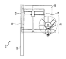
- the conventional banknote delivery unit 610 forms a space for storing banknotes BL (hereinafter referred to as an accumulation space SC) inside a rectangular parallelepiped frame 621.
- the bills BL are stored in the stacked space SC in an upright state, that is, stacked such that their paper faces face each other, and the short direction is directed up and down.
- the banknote delivery unit 610 is provided with a shutter 622 that can be opened and closed on a part of the integrated space SC, for example, on the upper surface side, from the viewpoint of reducing noise and ensuring safety.
- the banknote delivery unit 610 conveys the banknotes BL to be withdrawn one by one from the inside of the apparatus with the shutter 622 closed, and discharges it into the accumulation space SC by the discharge unit 28.
- the sheets are sequentially stacked, the shutter 622 is opened, and the operator takes out the bills BL from the stacking space SC.
- the banknote handling apparatus 601 is configured such that when the operator OP faces the customer CS across the counter CT at the counter of the financial institution, It is installed adjacent to the right or left side.
- the banknote handling apparatus 601 has a height similar to that of the waist when the operator OP sits on a chair, for example, and a banknote delivery section 610 serving as a withdrawal section is provided on the upper surface or a portion from the upper surface to the side surface. It has been.
- the banknote delivery unit 610 of the banknote handling apparatus 601 is viewed from the diagonally upper left and right rather than from right above by the operator OP sitting in a chair.
- the banknote BL of the inner SC is visually recognized.
- the banknote delivery unit 610 can store the banknotes BL having the longest length in the short direction. It is necessary to set a large height.
- the banknote delivery part 610 shields most banknotes BL by the peripheral side part, especially when banknote BL with a short length in the short direction is stored in the accumulation space SC. Can hardly be seen.
- the present invention has been made in consideration of the above points, and intends to propose a medium delivery apparatus and a medium processing apparatus that can improve the visibility of a medium delivered to an operator.
- Part, and at least a part of the adjacent side surface adjacent to the opposite side surface are opened, a fixed peripheral side portion that covers the other part, and a portion that is not covered by the fixed peripheral side portion of the side surface surrounding the accumulation space
- a cover portion that is shaped to cover the cover a closed state in which the cover portion is closed or brought into contact with the fixed peripheral side portion to close the collection space, and at least a part of the cover portion is separated from the fixed peripheral side portion to open the collection space.
- a transition part for changing the lid part with respect to the fixed peripheral side part and a transfer part for transferring the medium between the inside and outside of the accumulation space are provided.
- the opposite side surface that faces the medium support portion that supports the medium in the collection space. At least a part and at least a part of an adjacent side surface adjacent to the opposite side surface are opened, and are covered with a fixed peripheral side portion that covers the other portion and a fixed peripheral side portion of the side surface that surrounds the accumulation space.
- a transition portion that causes the lid portion to transition with respect to the fixed peripheral side portion, a conveyance portion that conveys the medium, and a transfer portion that exchanges the medium between the conveyance portion and the accumulation space It was made to provide.
- the medium delivery device and the medium processing device can ensure quietness and safety when the medium is transferred by the transfer unit in the closed state, while the medium in the collection space is placed on the opposite side in the open state.
- the medium can be taken out from or put into the accumulation space while allowing the operator to visually recognize not only from the adjacent side surface side.
- quietness and safety can be secured when the medium is transferred by the transfer unit in the closed state, while the medium in the accumulation space is not only from the opposite side surface side but also from the adjacent side surface side in the open state.
- the medium can be taken out from or put into the accumulation space while being visually recognized by an operator (user).
- it is possible to realize a medium delivery apparatus and a medium processing apparatus that can improve the visibility of a medium delivered to a user.
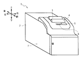
- FIG. 1 the external appearance structure of the banknote processing apparatus 1 is shown.
- This banknote processing apparatus 1 is a cash processing apparatus for a counter installed at a counter of a financial institution, etc., and is operated by an operator (user) such as a counter in charge of dealing with a customer at the counter. The deposit and withdrawal processing is done.
- the banknote handling apparatus 1 is provided with a depositing unit 3, a dispensing unit 4, a display unit 5, and an operation unit 6 on the upper surface of a casing 2 formed in a rectangular parallelepiped shape as a whole.
- the depositing unit 3 is mainly configured to deposit bills, and when the bills are inserted by the user, the deposit unit 3 takes the bills into the bill processing apparatus 1.
- the withdrawal unit 4 is configured to mainly withdraw banknotes, and is configured to accumulate the banknotes transported from within the banknote processing apparatus 1 and allow the user to take them out.
- the display unit 5 is, for example, a liquid crystal display, and displays a menu screen, a result screen of various processes, and the like.
- the operation unit 6 is formed of a button, for example, and receives an operation on the banknote processing apparatus 1.
- the display unit 5 and the operation unit 6 are provided separately, but the display unit 5 and the operation unit 6 are integrated with each other using, for example, a liquid crystal display with a touch sensor (so-called touch panel). You may make it provide in.
- the control unit 7 is configured around a CPU (Central Processing Unit) (not shown), and reads and executes a predetermined program from a ROM, a flash memory, etc. (not shown), thereby performing a deposit process, a withdrawal process, and the like. Various processes are performed.
- a CPU Central Processing Unit
- ROM Read Only Memory
- flash memory etc.
- the control unit 7 has a storage unit including a RAM (Random Access Memory), a hard disk drive, a flash memory, and the like, and stores various information in the storage unit.
- RAM Random Access Memory
- the banknote processing apparatus 1 is connected to a terminal or host computer of a financial institution via a network from a communication processing unit (not shown), and transmits / receives various kinds of information to / from the terminal or host computer. It is also configured to be.
- the front side which can read the display content of the display part 5 correctly among banknote processing apparatuses 1 is made into the front side, the opposite is made into the back side, the left and right when it sees from the front side are made into the left side and the right side, respectively, and further upper side
- the lower side is defined and described.
- the banknote processing apparatus 1 is installed adjacent to the right side or the left side of a user sitting on a chair at a window of a financial institution or the like, similar to the conventional banknote processing apparatus 601 (FIG. 20).
- the depositing unit 3 and the dispensing unit 4 are arranged in the front-rear direction so that the depositing unit 3 is on the rear side and the dispensing unit 4 is on the front side of the upper portion in the upper part of the housing 2. Is provided.
- the withdrawal unit 4 includes a banknote delivery unit 10 for delivering banknotes to and from the user.
- This banknote delivery part 10 is comprised so that the banknote sent from the inside of an apparatus may be accumulated and a user may take out.
- the discrimination unit 11 is arranged on the lower rear side of the depositing unit 3 and can be handled based on the denomination, authenticity, correctness, running state, etc. of the bill conveyed by the conveyance unit 15. Or rejected banknotes that cannot be handled, and the result of the discrimination is sent to the control unit 7.
- the temporary storage unit 12 is disposed on the lower front side of the dispensing unit 4, temporarily holds the banknotes transported by the transport unit 15, and transports the banknotes held one by one. 15 is sent out.
- a reject box 14 is disposed on the foremost side, and banknote cassettes 13A, 13B, 13C, and 13D are sequentially arranged on the rear side from the front to the rear.
- the banknote cassettes 13A to 13D are stored in a state in which banknotes are accumulated therein, and each is assigned a denomination.
- the banknote cassettes 13A to 13D stack the banknotes (normal banknotes) conveyed from the conveyance unit 15 in the vertical direction and store them inside, and feed out the banknotes stored one by one to the conveyance unit 15. It is made like that.
- the reject box 14 stores the reject banknotes transported from the transport unit 15 inside.
- the conveyance unit 15 includes various rollers and belts arranged along a conveyance path W that connects each part in the housing 2, and a gear and a motor for driving these rollers. Incidentally, in FIG. 2, only a part of the parts constituting the transport unit 15 is schematically shown.
- the transport unit 15 has a transport path switching mechanism (not shown) arranged at a branch point of the transport path W, and switches the banknote transport destination by the transport path switching mechanism based on the control of the control unit 7.
- the bill processing apparatus 1 first causes the user to insert bills into the bill delivery unit 10 of the deposit unit 3, separates them one by one, and sequentially sends them to the transport unit 15.
- the transport unit 15 sequentially transports the banknotes to the discrimination unit 11 along the transport path W.
- the discrimination unit 11 discriminates the banknotes one by one and sends the discrimination result to the control unit 7. At this time, the control part 7 determines the conveyance destination of each banknote based on whether it is a discrimination result acquired from the discrimination part 11, ie, a normal banknote or a reject banknote.
- the normal banknote is transported to the temporary storage section 12 by the transport section 15 and temporarily stored, and then transported to the discrimination section 11 again to determine the denomination and to the banknote cassettes 13A to 13D corresponding to the denomination. It is transported and stored. Further, the reject banknote is transported to the reject storage 14 by the transport unit 15 and stored therein.
- the banknote handling apparatus 1 accepts an instruction for a withdrawal amount from a terminal (not shown) or the like when a withdrawal process is performed. Based on the control of the control unit 7, the denomination and the number of coins according to the withdrawal amount are determined from the bill cassettes 13A to 13D. Are sequentially fed out to the transport unit 15.
- the transport unit 15 discriminates the denominations and correctness of the fed banknotes by the discrimination unit 11 and sequentially delivers them to the banknote delivery unit 10 of the withdrawal unit 4.
- the banknote delivery unit 10 of the withdrawal unit 4 accumulates banknotes delivered from the transport unit 15 and causes the user to take them out.
- the banknote handling apparatus 1 is configured to take out banknotes from the banknote delivery unit 10 constituting the withdrawal unit 4 in the withdrawal process.
- the structure of the banknote delivery part 10 is demonstrated.
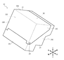
- the bill delivery unit 10 has a shape such that a rectangular parallelepiped that is long in the left-right direction and short in the front-rear direction is rotated clockwise as viewed from the left side.
- the shutter 22 is roughly divided.
- the banknote delivery unit 10 has the longest ridge line along the horizontal direction among the ridge lines in the three directions constituting the rectangular parallelepiped, but the other two ridge lines are set to a predetermined angle ⁇ (for example, about It is attached to the housing 2 (FIGS. 1 and 2) in an inclined state by 30 degrees.
- the directions inclined by the angle ⁇ clockwise from the front direction and the rear direction as viewed from the left are respectively referred to as the forward direction and the backward direction, and the angles ⁇ from the upward direction and the downward direction are respectively clockwise.
- the directions inclined only by this are referred to as the upward and downward inclination directions, respectively.
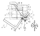
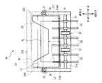
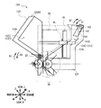
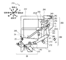
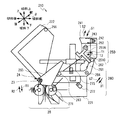
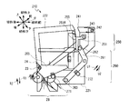
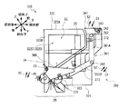
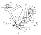
- FIGS. 4A and 4B show a left side view and a rear side view of the banknote delivery unit 10, respectively. For convenience of explanation, each part is schematically shown in FIGS. 4A and 4B, and some parts are transparently displayed. 4A and 4B show the upward and downward directions as the upward and downward directions, respectively.
- the frame 21 has such a shape that approximately half of the upper side of the upper surface and the rear side surface of the hollow rectangular parallelepiped and the upper side of the left and right side surfaces are cut off. All of the upper part of the rear side of the slope and the upper half of the left and right side surfaces are open.
- the frame 21 is the lower side of the slope, and is composed of a lower part 21A as a medium support part, a front side part 21B on the front side of the slope, a left side part 21C on the left side, a right side part 21D on the right side, and a rear side part 21E on the rear side.
- the shutter 22 has a cut-off portion of the hollow rectangular parallelepiped, that is, an upper portion 22A that is an inclined upper side surface as an opposing side surface, a rear portion 22B that is an upper portion on the inclined rear side, and left and right as adjacent side surfaces.
- the left side portion 22C and the right side portion 22D have a right triangular shape that is about half of the upper side.
- the integrated space which consists of a rectangular parallelepiped space slightly smaller than the external shape of the said banknote delivery part 10 concerned. SC can be formed inside.
- the bills BL are stacked in a state in which the paper surface is directed in the forward and backward direction and the long side is in contact with the bottom surface 21AX of the lower portion 21A.
- the size of the bill BL handled in the bill processing apparatus 1 is different depending on the denomination. There are many.
- the length L1 (FIG. 4A) of the direction connecting the inclined upward direction and the inclined downward direction in the accumulation space SC (hereinafter referred to as the inclined vertical direction) is any banknote handled in the banknote handling apparatus 1 (FIG. 1). It is longer than the short length of BL. Moreover, the length L2 (FIG. 4B) in the left-right direction in the accumulation space SC is longer than the longitudinal length of any banknote BL handled in the banknote handling apparatus 1.
- the front side portion 21B of the frame 21 has the upper portion of the integrated space SC extended forward by folding the upper portion forward in a crank shape.
- a plate-like stage 25 is provided so that the plate surface is directed in the front-back direction.
- the stage 25 is formed in a plate shape that is thin in the front-rear direction and long in the left-right direction, and a wide range extending from the upper center to the vicinity of both left and right ends is largely cut out in a trapezoidal shape (FIG. 4B).
- the length L3 from the upper end of the center portion of the stage 25 to the bottom surface 21AX, which is the upper surface of the lower portion 21A of the frame 21, is shorter than the short length of the bill BL with the shortest length handled in the bill processing apparatus 1. Yes.
- the central portion of the upper long side of the banknotes BL is placed from the upper end of the stage 25. Can also be exposed to the upper side.
- the small rectangular parallelepiped support portions 26 are attached to the left and right ends of the stage 25, respectively.
- the support part 26 is drilled so that a shaft hole formed of a round hole or a long hole penetrates in the front-rear direction.
- elongated cylindrical sliding shafts 27 are provided along the front-back direction.
- the sliding shaft 27 is inserted through the shaft hole of the support portion 26.
- the support portion 26 is supported by a spring (not shown). For this reason, when the bills BL are placed, the stage 25 can move along the slanting front-rear direction according to the weight of the bills BL while sliding the support portions 26 on the slide shafts 27.
- a conveyance path 21 ⁇ / b> H made of a long slit-like long hole is drilled so as to penetrate in the vertical direction.
- discharge sections 28 that transport the banknote BL along the transport path 21H and discharge the banknote BL into the accumulation space SC. It has been.
- the discharge unit 28 serving as a transfer unit includes a drive shaft 31, a feed roller 32, and an impeller 33 disposed on the front side of the conveyance path 21H, and an idle shaft 34 and a driven roller 35 disposed on the rear side of the conveyance path 21H.
- the spring 36, the conveying path 21 ⁇ / b> H is configured to be sandwiched between the front and rear directions.
- the drive shaft 31 is formed in an elongated cylindrical shape, is positioned on the front side of the inclination with respect to the inner surface of the conveyance path 21H, and has its central axis directed in the left-right direction.
- the drive shaft 31 is rotatably supported by a bearing (not shown), and is rotated clockwise or counterclockwise in the drawing when a driving force from an actuator (not shown) is transmitted.
- the feed roller 32 is formed in a thin cylindrical shape with the central axis directed in the left-right direction, and is inserted through two locations that are separated from the left-right center of the drive shaft 31 by a predetermined distance. Further, the feed roller 32 exposes a part of the feed roller 32 into the transport path 21H from a predetermined hole formed in the inner surface of the transport path 21H.
- the feed roller 32 is attached to a part of the peripheral side surface with a high friction member having a larger coefficient of friction with respect to the banknote BL than other parts.
- the impeller 33 includes a central portion formed in a small and thin disc shape and a plurality of tongue pieces extending radially from the central portion.
- the tongue piece is made of a flexible material and is formed in a rod shape or an elongated plate shape.
- the impeller 33 is inserted into the drive shaft 31 in a total of six places, two places between the feed rollers 32 and two places on the left and right outer sides of the feed rollers 32 so as to be appropriately spaced from each other. Yes.
- the impeller 33 exposes a part of the impeller 33 from the inner surface of the conveyance path 21H to the bottom surface 21AX of the frame 21 into the conveyance path 21H and the accumulation space SC.
- the idle shaft 34 is formed in an elongated cylindrical shape like the drive shaft 31, and is provided at a position facing the drive shaft 31 across the conveyance path 21 ⁇ / b> H, that is, on the inclined rear side of the drive shaft 31. .
- the idle shaft 34 is supported by a support mechanism (not shown) so as to be displaceable in the front-rear direction.
- the driven roller 35 is formed in a thin cylindrical shape with the central axis directed in the left-right direction.
- the driven roller 35 is inserted into two portions of the idle shaft 34 facing the feed roller 32, and can be freely rotated with respect to the idle shaft 34. Further, the driven roller 35 exposes a part of the driven roller 35 into the transport path 21H from a predetermined hole formed on the inner surface of the transport path 21H.
- the spring 36 is a coil spring that can be expanded and contracted, and an end portion on the rear side of the tilt is attached to the frame 21, and an end portion on the front side of the tilt is attached to the idle shaft 34.
- the spring 36 is shortened from the natural state in the forward / backward direction of the tilt, so that a restoring force is applied to the idle shaft 34 in the forward direction of the tilt, and the driven roller 35 is pressed against the feed roller 32.
- the discharge unit 28 can feed the bill BL upward or downward by sandwiching the bill BL between the feed roller 32 and the driven roller 35 and rotating the feed roller 32. .
- the shutter 22 is attached to the frame 21 via the rotation shaft 23 at both left and right ends of the rear side surface.
- the rotation shaft 23 is opened in a counterclockwise direction when the shutter 22 is viewed from the left side with respect to the frame 21 with the axis extending in the left-right direction as the rotation center when a driving force from an actuator (not shown) is transmitted. It is rotated in the closing direction R2 which is the direction R1 or the opposite (FIG. 4A).
- the range in which the shutter 22 can rotate is restricted by the frame 21 within a predetermined rotation range.
- a spring 24 for urging the shutter 22 in the closing direction R2 with respect to the frame 21 is provided.
- the spring 24 is a so-called torsion spring, and is designed to have a relatively weak biasing force that allows the user to rotate the shutter 22 in the opening direction R1 against the biasing force by a fingertip, for example. Yes.
- the shutter 22 closes the upper and left and right upper portions of the integrated space SC, and can shield the integrated space SC from the outside.
- the shutter 22 is made of a resin material having a high light transmission property so that the user can visually recognize the state in the integrated space SC in this closed state.
- the shutter 22 opens the left and right upper portions in addition to the inclined upper side of the integrated space SC to communicate the integrated space SC with the external space. Can be made.
- the banknote delivery unit 10 rotates the shutter 22 with respect to the frame 21 by the rotation shaft 23 to close the accumulation space SC with the shutter 22 closed, or with the shutter 22 open.
- the upper and left upper portions of the accumulation space SC are opened.
- the banknote delivery unit 10 sequentially sends out the banknotes BL sequentially delivered from the transport unit 15 (FIG. 2) by the ejection unit 28 in an upwardly tilted direction and discharges them to the accumulation space SC.
- the banknote delivery unit 10 strikes the banknote BL released into the accumulation space SC forward by the impeller 33 and further moves the stage 25 to the front side of the tilt.
- the bills BL are sequentially stacked and accumulated on the inclined rear side surface of the stage 25 while the long side is in contact with the bottom surface 21AX of the frame 21 in the accumulation space SC.
- the banknote delivery part 10 will rotate the shutter 22 by the rotating shaft 23, and will be in an open state, if all the banknote BL which should be withdrawn is accumulated in the accumulation space SC (FIG. 4A, FIG. 5). The user can take out the bill BL.
- the banknote delivery part 10 can interrupt
- the banknote delivery unit 10 can open not only the inclined upper side of the accumulation space SC but also the right and left sides as shown in FIG.
- the banknote delivery part 10 makes a user's viewpoint of the attitude
- the banknote BL can be taken out while the banknote BL in the stacking space SC is visually recognized.
- some of the conventional banknote delivery sections are configured to improve the visibility of the accumulation space SC by improving the banknote delivery section 610 (FIGS. 19A and 19B) described above.
- the conventional banknote delivery unit 710 opens and closes only the upper surface of the accumulation space SC by the shutter 622 in the same manner as the conventional banknote delivery unit 610.
- the banknote delivery unit 710 has an upper portion on the front side of the frame 721 bent forward in a crank shape, and a central portion on the upper side of the stage 725 is largely cut out in a trapezoidal shape.
- this banknote delivery part 710 can improve the visibility with respect to the accumulation space SC from the front upper direction and the operativity in taking-out operation of banknote BL with respect to the banknote delivery part 610 (FIG. 19A and B), it is from right and left upper direction. There was no difference in the visibility of and remained low.
- the conventional banknote delivery unit 810 opens and closes only the upper surface of the accumulation space SC by the shutter 622 similarly to the conventional banknote delivery unit 610.
- the banknote delivery unit 810 is inclined so that the upper part of the front side surface of the frame 721 is bent forward in a crank shape, and the upper part of the stage 825 is bent obliquely forward.
- the banknote delivery unit 810 like the banknote delivery unit 110, improves the visibility with respect to the stacking space SC from the front upper side and the operability in the banknote BL takeout operation with respect to the banknote delivery unit 610 (FIGS. 19A and B). Although it was possible, there was no difference in the visibility from the upper left and right, and it remained low.
- the banknote delivery unit 10 deletes the left and right upper parts of the frame 21, that is, the left and right upper parts of the accumulation space SC, and provides the left part 22 ⁇ / b> C and the right part 22 ⁇ / b> D on the left and right of the shutter 22. It was. For this reason, the banknote delivery part 10 can improve visibility from right and left upper part markedly.
- the banknote delivery unit 10 like the conventional banknote delivery unit 710 (FIGS. 6A and 6B), has an upper portion on the front side of the frame 21 bent forward in a crank shape and a large central portion on the upper side of the stage 25. It is missing. For this reason, the banknote delivery part 10 can also improve the operativity in taking out banknote BL while improving the visibility from front upper direction.
- the banknote delivery unit 10 is configured so that the upper half of the accumulation space SC in the frame 21, the upper part of the rear side of the inclination, and the upper half of the left and right side surfaces are approximately half. These portions were covered with an upper portion 22A, a rear portion 22B, a left portion 22C, and a right portion 22D of the shutter 22, respectively. Further, the banknote delivery unit 10 is configured to rotate the shutter 22 by the rotation shaft 23 on the rear side with respect to the frame 21. As a result, the bill delivery unit 10 shields the accumulation space SC from the surroundings when the shutter 22 is closed, and opens the inclined upper and left and right upper portions when the shutter 22 is opened. The visibility with respect to SC can be improved.
- the banknote delivery part 110 replaced with the banknote delivery part 10 is used as the payment
- the banknote delivery section 110 is provided with a frame 121 and a shutter 122 instead of the frame 21 and the shutter 22, and a second shutter 141, a rotating shaft 142, and a spring. Although different in that 143 is added, the other parts are configured in the same manner.
- the shutter 122 has a shape in which a part of the front side of the tilt in the closed state (shown by a broken line in the figure) is cut off as compared with the shutter 22 according to the first embodiment.
- the upper part 122A of the shutter 122 is shortened in the front-rear direction than the upper part 22A of the shutter 22. Further, the left side 122C and the right side 122D of the shutter 122 are formed in a trapezoidal shape by cutting off the front end portions of the left side 22C and the right side 22D of the shutter 22, respectively.
- the front end 122AX of the upper part 122A of the shutter 122 is inclined with respect to the up and down direction so that the end face is slightly inclined upward.
- the frame 121 is configured to cover the left and right side portions in the integrated space SC so as to cover the remaining portions not covered by the shutter 122, and the shape is different from that of the frame 21 according to the first embodiment.
- the left side 121C and the right side 121D of the frame 121 have a shape in which only a part of the left side 21C and the right side 21D of the frame 21 on the front side of the slope is extended upward in the slope.
- the frame 121 removes the portions corresponding to the left side portion 122C and the right side portion 122D of the shutter 122 from the left side portion 22C and the right side portion 22D of the shutter 22 in the first embodiment, and the remaining portion is the first portion.
- the shape is such that it is coupled to the left side portions 21C and 22C of the frame 21 in the first embodiment.
- a shutter 122 is rotatably attached to the frame 121 via a rotation shaft 23.
- the banknote delivery part 110 rotates the shutter 122 with respect to the flame
- the said shutter 122 is in the obstruction
- a second shutter 141 serving as a second lid is attached to the upper end of the front side 121B of the frame 121 via a rotating shaft 142.
- the second shutter 141 is formed in a plate shape that is thin in the vertical direction of the inclination and short in the longitudinal direction of the inclination, and covers the remaining portion that is not covered by the shutter 122. Yes.
- the second shutter 141 corresponds to a remaining portion when the portion corresponding to the upper portion 122A of the shutter 122 is removed from the upper portion 22A of the shutter 22 in the first embodiment.
- end portion 141X on the rear side of the second shutter 141 is inclined slightly downward, and is inclined with respect to the vertical direction so as to correspond to the end portion 122AX of the upper portion 122A of the shutter 122. .
- the rotation shaft 142 is configured in the same manner as the rotation shaft 23, and rotates in the opening direction S1 that is counterclockwise when the second shutter 141 is viewed from the left side with respect to the frame 121 or in the closing direction S2 that is opposite thereto. I support you to let me.
- the second shutter 141 is restricted by the frame 121 so as to rotate within a predetermined rotation range.
- a spring 143 for urging the second shutter 141 in the closing direction S2 with respect to the frame 121 is provided.
- the second shutter 141 is positioned on the upper side of the integrated space SC with the end 141X facing the inclined rear side by the action of the spring 143 as shown by the broken line in FIG. The second closed state.
- the second shutter 141 is restricted from rotating in the opening direction S1 by the end portion 141X interfering with the front end portion 122AX of the upper portion 122A of the shutter 122. .
- the second shutter 141 when the shutter 122 is in an open state and an external force larger than the urging force of the spring 143 is applied downward or downward, as shown by the solid line in FIG. It turns to the opening direction S1 from a closed state, and it will be in the 2nd open state which orient
- the second shutter 141 rotates in the closing direction S2 by the action of the spring 143, and eventually returns to the second closed state.
- the banknote delivery unit 110 transitions to the closed state or the open state by rotating the shutter 122 with respect to the frame 121 by the rotation shaft 23, and at the same time the second shutter 141 with respect to the frame 121 by the rotation shaft 142. Can be shifted to the second closed state or the second open state.
- the banknote delivery unit 110 is configured such that the shutter 122 is rotated in the closing direction R2 with respect to the frame 121 by the rotation shaft 23 based on the control of the control unit 7. Is in the closed state, the shutter 122 covers the range from the middle to the rear side of the slope in the upper part and the left and right upper parts of the integrated space SC.
- the banknote delivery unit 110 urges the second shutter 141 in the closing direction S2 by the urging force of the spring 143, thereby covering the front side portion of the accumulation space SC on the upper side of the accumulation space SC with the second shutter 141. State.
- the bill delivery unit 110 can shield the accumulation space SC from the external space by the frame 121, the closed shutter 122 and the second closed shutter 141.
- the banknote delivery part 110 has located the edge part 122AX in the upper part 122A of the shutter 122 on the inclination lower side of the edge part 141X of the 2nd shutter 141, even if external force is applied with respect to the said 2nd shutter 141, The rotation is suppressed and the second closed state is stopped.
- the banknote delivery part 110 can interrupt
- the banknote delivery unit 110 is configured such that the length of the shutter 122 in the front-rear direction is shorter than the shutter 22 in the first embodiment.
- the banknote delivery part 110 rotates the shutter 122 centering on the rotating shaft 23
- the space required for rotation of the shutter 22 can be restrained smaller than 1st Embodiment. It is possible to reduce the space to be vacated during the operation of the banknote handling apparatus 1.
- the banknote delivery part 110 rotates the shutter 122 to the opening direction R1 with respect to the flame
- the banknote delivery part 110 can open
- the visibility with respect to the banknote BL in the accumulation space SC from the diagonally upper left and right which is a user's viewpoint. Can be significantly increased.
- the banknote delivery unit 110 urges the second shutter 141 in the closing direction S2 by the urging force of the spring 143, but an external force stronger than the urging force of the spring 143 is applied to the tilt downward by the user's finger or the like. Then, the second shutter 141 is rotated in the opening direction S1, and the second open state is set with the end portion 141X facing downward on the slope.
- the banknote delivery part 110 can expand the opening range in the inclination upper side of stacking space SC to the same extent as 1st Embodiment, a user's fingertip is integrated at the time of insertion and taking out of banknote BL.
- the space SC can be smoothly taken in and out, and the bills BL in the accumulation space SC can be easily gripped.
- the banknote delivery unit 110 divides the shutter 22 into two in the tilted front-rear direction to form the shutter 122 and the second shutter 141, and has different rotation axes. It was made to rotate to the center respectively.
- the banknote delivery part 110 can raise the visibility of the banknote BL in an open state to the same extent, can also ensure the operativity in insertion and taking-out of the banknote BL to the same extent, and has the space which should be vacated around. It can be kept smaller.
- the banknote delivery part 110 can show
- the banknote delivery unit 110 covers the upper half of the upper side of the inclined upper side of the accumulation space SC, the upper side of the inclined rear side, and the left and right side surfaces of the frame 121. These portions were covered and covered with the shutter 122 and the second shutter 141. Further, the banknote delivery unit 110 rotates the shutter 122 with respect to the frame 121 by the rotation shaft 23 on the rear side of the tilt and rotates the second shutter 141 by the rotation shaft 142 on the front side of the tilt. Thereby, the banknote delivery unit 110 shields the accumulation space SC from the surroundings when the shutter 122 is closed and the second shutter 141 is set to the second closed state. Most of the left and right upper sides are opened to increase the visibility of the accumulation space SC, and the user can rotate the second shutter 141 to the second opened state to improve the operability when taking out the bill BL. .
- the banknote delivery part 210 replaced with the banknote delivery part 10 is used as the payment
- the banknote delivery unit 210 is provided with a frame 221 and a shutter 222 instead of the frame 21 and the shutter 22, and a second shutter 241, a rotating shaft 242, a spring.
- the lock mechanism portion 250, and the link mechanism portion 260 are added, the other portions are configured similarly.
- the frame 221, the second shutter 241, the rotating shaft 242 and the spring 243 are configured in substantially the same manner as the frame 121, the second shutter 141, the rotating shaft 142 and the spring 143, respectively, in the second embodiment.
- the shutter 222 is configured in substantially the same shape as the shutter 122 according to the second embodiment, and the upper part 222A, the rear part 222B, the left part 222C, and the right part 222D cover the upper part of the integrated space SC.
- the shutter 222 is rotatably attached to the frame 221 via the rotation shaft 23, and, like the shutter 122, is opened by rotating in the opening direction R1, and is rotated in the closing direction R2. It becomes a closed state by being moved.
- the driving force from the actuator or the like is not transmitted to the rotating shaft 23. That is, the shutter 222 is urged with a relatively weak force in the closing direction R ⁇ b> 2 by the action of the spring 24.
- the shutter 222 is provided with a lock post 255 and a cam plate 265.
- the lock post 255 is formed in a small and short columnar shape, and is erected in the vicinity of the end portion on the front side of the inclination on the inner side surface of the left side portion 222C with the central axis directed in the left-right direction.
- the cam plate 265 is formed in a triangular plate shape with the plate surface directed in the left-right direction as a whole, and the longitudinal direction is inclined in the vicinity of the lower end of the left side portion 222C, that is, in the vicinity of the rotating shaft 23. It is attached to face in the front-rear direction.
- the lock mechanism part 250 as an engaging part is configured by a lock lever 251, a rotation shaft 252 and the lock post 255 described above.
- the lock lever 251 is a thin plate-like member in the left-right direction, is formed in a “T” shape or a “Y” shape when viewed from the left-right direction, and has an elongated base portion 251A whose longitudinal direction is the front-back direction. It is structured in the center.
- a lock arm 251B extends shortly toward the upper end of the tilt at the rear end of the base 251A.
- a link arm 251C is extended relatively long toward a downwardly inclined direction at a portion of the base portion 251A that is slightly inclined toward the rear side of the inclination from the center in the direction of inclination.
- lock lever 251 is supported by the rotation shaft 252 so as to be rotatable with respect to the frame 221 at an end portion on the front side of the base portion 251A.
- the lock lever 251 can freely rotate with respect to the frame 221 in a release direction T1 that is counterclockwise when viewed from the left side or a lock direction T2 that is the opposite direction.
- the lock lever 251 is urged in the release direction T1 by a spring (not shown).
- the lock mechanism portion 250 moves the lock arm 251 ⁇ / b> B to the rear side of the lock post 255 when the shutter 222 is closed and the base portion 251 ⁇ / b> A is directed substantially rearward from the rotation shaft 252. Position.
- the lock lever 251 restricts the rotation of the shutter 222 about the rotation shaft 23 in the opening direction R1 in order to restrict the movement of the lock post 255 to the rear side or the upper side by the lock arm 251B.
- a state in which the lock arm 251B of the lock lever 251 is positioned on the rear side of the lock post 255 is referred to as a locked state.
- the lock mechanism portion 250 retracts the lock arm 251 ⁇ / b> B from the inclined rear side of the lock post 255 when the lock lever 251 is rotated in the unlocking direction T ⁇ b> 1 from the locked state. .
- the shutter 222 allows the shutter 222 to rotate in the opening direction R1 around the rotation shaft 23.
- a state in which the lock arm 251B of the lock lever 251 is retracted from the inclined rear side of the lock post 255 will be referred to as a lock release state.
- the lock mechanism 250 is configured to transition to the locked state or the unlocked state by rotating the lock lever 251 in the unlocking direction T1 or the locking direction T2.
- the link mechanism part 260 (FIG. 9) as an engagement interlocking part is comprised by the link lever 261, the link posts 262 and 263, the rotating shaft 264, and the cam plate 265 mentioned above.
- the link lever 261 is a thin plate-like member in the left-right direction, and is roughly composed of a first arm 261A and a second arm 261B each formed in an elongated rectangular shape.
- the first arm 261A has its longitudinal direction substantially in the vertical direction.
- a small cylindrical link post 262 is erected at the upper end of the first arm 261A so that the central axis thereof is directed in the left-right direction.
- the link post 262 abuts the peripheral side surface on the rear side of the tilt against the front side surface of the link arm 251 ⁇ / b> C on the lock lever 251.
- the second arm 261B has its longitudinal direction substantially in the front-rear direction.
- a small cylindrical link post 263 is erected at the rear end of the second arm 261B so that the central axis thereof is directed in the left-right direction.
- the link lever 261 connects the lower end portion of the first arm 261A and the front end portion of the second arm 261B to each other, and seems to intersect the longitudinal direction of the two at an angle of about 90 to 120 degrees.
- the shape is generally “L”.
- link lever 261 is supported by the rotating shaft 264 so as to be rotatable with respect to the frame 221 at the connecting portion of the first arm 261A and the second arm 261B.
- the link lever 261 freely rotates with respect to the frame 221 in the link open direction U1 that is clockwise when viewed from the left side or the link close direction U2 that is the opposite direction. It is made to move.
- the link mechanism 260 causes the link post 262 to contact the link arm 251 ⁇ / b> C of the lock lever 251 in the locked state.
- the link post 262 restricts the rotation of the lock lever 251 urged in the unlocking direction T1 by a spring (not shown), and stops the lock mechanism 250 in the locked state.
- the link post 263 is not in contact with other parts.
- a state of the link mechanism unit is referred to as a link closed state.
- the link post 262 is moved in the forward direction or the forward tilt direction from the link closed state.
- the lock lever 251 rotates in the unlocking direction T1 while bringing the link arm 251C into contact with the link post 262 by an urging force of a spring (not shown), and enters the unlocked state.
- the shutter 222 can be rotated in the opening direction R1 about the rotation shaft 23.
- the link mechanism portion 260 further rotates the link lever 261 in the link open direction U1 from the state shown in FIG. 10, the link post 263 applies a force directed upward to the lower side of the cam plate 265.
- the shutter 222 is gradually rotated in the opening direction R1, and eventually the shutter 222 is opened as shown in FIG.
- the link post 262 further moves in the forward direction or in the forward tilt direction as the link lever 261 rotates in the link open direction U1. At this time, the lock lever 251 is further rotated in the unlocking direction T1 while bringing the link arm 251C into contact with the link post 262.
- link open state the state of the link mechanism 260 in which the link lever 261 is rotated in the link open direction U1 and the shutter 222 is opened is referred to as a link open state.
- the link mechanism 260 changes the link open state or the link close state by rotating the link lever 261 in the link open direction U1 or the link close direction U2.
- the bill delivery unit 210 is provided with a shutter detection sensor 271, a link close detection sensor 272, and a link open detection sensor 273.
- the shutter detection sensor 271 is disposed on the left side of the cam plate 265 and emits predetermined detection light.
- the shutter detection sensor 271 is disposed on the right side of the cam plate 265 and receives the detection light. 7 (FIG. 2).
- the shutter detection sensor 271 is attached to the frame 221 at a position where the detection light is irradiated in the vicinity of the lower end of the cam plate 265 when the shutter 222 is closed.
- the shutter detection sensor 271 does not receive the detection light by the light receiving unit because the detection light is blocked by the cam plate 265.
- the shutter detection sensor 271 does not block the detection light by the cam plate 265. Is received.
- control unit 7 can recognize whether or not the shutter 222 is closed based on the detection signal from the shutter detection sensor 271.
- the link close detection sensor 272 is configured in the same manner as the shutter detection sensor 271, the link close detection sensor 272 is attached to a position where the detection light is irradiated near the lower end of the second arm 261B when the link lever 261 is in the link close state. Yes.
- the link close detection sensor 272 does not receive the detection light by the light receiving unit because the detection light is blocked by the second arm 261B.
- the link close detection sensor 272 is not shielded by the second arm 261B. Receives detection light.
- control unit 7 can recognize whether or not the link mechanism unit 260 is in the link closed state based on the detection signal from the link close detection sensor 272.
- the link open detection sensor 273 is configured in the same manner as the shutter detection sensor 271, but is attached to a position where the detection light is irradiated near the upper end of the second arm 261B when the link lever 261 is in the link open state. Yes.
- the link open detection sensor 273 does not receive the detection light by the light receiving unit because the detection light is blocked by the second arm 261B.
- the link open detection sensor 273 is not shielded by the second arm 261B. Receives detection light.
- control unit 7 can recognize whether or not the link mechanism unit 260 is in the link open state based on the detection signal from the link open detection sensor 273.
- the banknote delivery unit 210 can be rotated while applying force between the shutter 222, the lock lever 251 and the link lever 261, and the control unit 7 can recognize the state of the shutter 222 and the link lever 261.
- control unit 7 changes the shutter 222 of the banknote delivery unit 210 from the closed state (FIG. 9) to the open state (FIG. 11), the control unit 7 executes a process according to the shutter open processing procedure RT1 shown in FIG.
- control unit 7 first starts the shutter release processing procedure RT1 and proceeds to step SP1.
- control unit 7 drives the actuator (not shown) to start the rotation of the link lever 261 in the link open direction U1, and proceeds to the next step SP2.
- link lever 261 rotates in the link opening direction U1 to bring the link post 263 into contact with the lower portion of the cam plate 265, and then opens the shutter 222 from the link post 263 via the cam plate 265. Turn to R1.
- step SP2 the control unit 7 acquires a detection signal from the link open detection sensor 273, and proceeds to the next step SP3.
- the control unit 7 determines whether or not the link lever 261 has transitioned to the link open state based on the detection signal acquired from the link open detection sensor 273.
- step SP4 the control unit 7 waits for a predetermined time (for example, 0.1 second), thereby further rotating the link lever 261 in the link open direction U1 and further rotating the shutter 222 in the open direction R1. Return to step SP2 again and wait for a transition to the link open state.
- a predetermined time for example, 0.1 second
- step SP3 if an affirmative result is obtained in step SP3, this indicates that the link lever 261 has finished transitioning to the link open state, and thus the shutter 222 has also transitioned to the open state (FIG. 11).
- the unit 7 proceeds to the next step SP5.
- step SP5 the control unit 7 stops the rotation of the link lever 261 by stopping driving of an actuator (not shown), moves to next step SP6, and ends the shutter release processing procedure RT1.
- the control unit 7 performs a process according to the shutter closing processing procedure RT2 shown in FIG. Has been made.
- control unit 7 first starts the shutter closing process procedure RT2 and proceeds to step SP11.
- control unit 7 drives the actuator (not shown) to start the rotation of the link lever 261 in the link closing direction U2, and proceeds to the next step SP12.
- link lever 261 moves the link post 262 in the backward tilt direction by rotating in the link closing direction U2, and accordingly, the lock lever 251 rotates in the locking direction T2, and eventually the lock lever 261 251 is locked (FIG. 9).
- step SP12 the control unit 7 acquires a detection signal from the link close detection sensor 272, and proceeds to the next step SP13.
- step SP13 the control unit 7 determines whether or not the link lever 261 has transitioned to the link closed state based on the detection signal acquired from the link close detection sensor 272.
- step SP14 the control unit 7 waits for a predetermined time (for example, 0.1 second), thereby further rotating the link lever 261 in the link closing direction U2 and further rotating the shutter 222 in the closing direction R2. The process returns to step SP12 again and waits for a transition to the link closed state.
- a predetermined time for example, 0.1 second
- step SP13 if a positive result is obtained in step SP13, this indicates that the link lever 261 has finished transitioning to the link closed state, and at this time, the control unit 7 moves to the next step SP15.
- step SP15 the control unit 7 stops the rotation of the link lever 261 by stopping driving of an actuator (not shown), and proceeds to the next step SP16.
- step SP16 the control unit 7 acquires a detection signal from the shutter detection sensor 271, and proceeds to the next step SP17.
- the control unit 7 determines whether or not the shutter 222 has transitioned to the closed state based on the detection signal acquired from the shutter detection sensor 271.
- the shutter 222 touches the user's hand or the like while the shutter 222 is rotating in the closing direction R2. It means that there was no.
- the lock post 255 is locked to the lock lever 251 that is already locked as shown in FIG. Indicates that the shutter 222 cannot transition to the closed state due to interference.
- the control unit 7 proceeds to the next step SP18.
- step SP18 the control unit 7 performs processing similar to the shutter opening processing procedure RT1 (FIG. 12) described above, thereby returning the link lever 261 to the link open state and returning the shutter 222 to the open state.
- step SP11 a series of processing is repeated.
- step SP17 if an affirmative result is obtained in step SP17, this means that the shutter 222 transitions to the closed state and the link lever 261 is in the link closed state, so that the lock lever 251 is in the locked state, and the lock post 255 is tilted. This indicates that the lock arm 251B is positioned on the rear side to restrict the rotation of the shutter 222 (FIG. 9).
- the control unit 7 proceeds to the next step SP19 and ends the shutter closing process procedure RT2.
- the banknote delivery unit 210 opens and closes the shutter 222 by rotating the link lever 261 based on the control of the control unit 7. Open once and close again.
- the banknote delivery unit 210 has the shutter 222 in the closed state, the lock lever 251 in the locked state, and the link lever 261 in the link closed state (hereinafter referred to as this).
- the integrated space SC is shielded from the outside (referred to as a closed lock state) (FIG. 9).
- the banknote delivery unit 210 can block noise caused by the operation of each unit in the discharge unit 28, the delivery of the banknote BL, and the like, and the user's fingertip with respect to the moving stage 25 and the like. It is possible to ensure safety by preventing such contact.
- the shutter 222 is held in a closed state via a lock post 255 by a lock lever 251 in a locked state. For this reason, the shutter 222 can be maintained in the closed state without being rotated even when a force acting in the opening direction R1 is applied from the outside, and thus the shutter 222 is inadvertently opened during the operation of the discharge unit 28 and the stage 25. Thus, the risk of injury to the user's finger or the like can be avoided.
- the banknote delivery unit 210 can be stopped in the second closed state because the rotation of the second shutter 241 is restricted by the shutter 222 as in the second embodiment.
- the link lever 261 moves the link post 263 upward to contact the lower portion of the cam plate 265, and applies an upward force to the shutter 222 via the cam plate 265, thereby the shutter. 222 is rotated in the opening direction R1 to be in an open state (FIG. 11).
- the banknote delivery unit 210 can open the left and right upper sides in addition to the upper slopes in the accumulation space SC, as in the first and second embodiments.
- the visibility with respect to the banknote BL in the accumulation space SC can be remarkably enhanced from above.
- the banknote delivery unit 210 is configured such that when an external force stronger than the urging force of the spring 243 is applied downwardly by the user's finger or the like, the second The shutter 241 is rotated in the opening direction S1 to enter the second open state.
- the banknote delivery part 210 can expand the opening range in the inclination upper side of stacking space SC to the same extent as 1st Embodiment, a user's fingertip is integrated at the time of insertion and extraction of banknote BL.
- the space SC can be smoothly taken in and out, and the bills BL in the accumulation space SC can be easily gripped.
- the banknote delivery part 210 only performs the rotation operation
- the bill delivery section 210 separates the link post 263 and the cam plate 265 when the link lever 261 is in the link closed state and the lock lever 251 is in the locked state (FIG. 9), and the lock lever 251 is moved from the locked state.
- the link post 263 and the cam plate 265 are brought into contact with each other.
- the banknote delivery unit 210 simply rotates the link lever 261 continuously in the link open direction U1 or the link close direction U2, and the shutter 222 is locked or unlocked via the cam plate 265. A time difference is provided between the rotation operation of the shutter 222 and both can be executed continuously at appropriate timing.
- the link post 263 moves the link post 263 downward as the link lever 261 rotates in the link closing direction U2 in the closing operation of the shutter 222, the link post 263 causes the cam plate 265 to move. Instead of pulling downward, the biasing force of the spring 24 in the closing direction R2 is used.
- the link post 263 is separated from the cam plate 265.
- the applied relatively strong driving force can be separated from the shutter 222, and only the relatively weak force of the spring 24 can be applied.
- the banknote delivery unit 210 can prevent an accident such as a user's fingertip being injured by being sandwiched between the shutter 222 and the second shutter 241 during the closing operation of the shutter 222.
- the banknote delivery unit 210 divides the shutter 22 into two parts in the forward and backward directions to form the shutter 222 and the second shutter 241 and is different from the first embodiment. It was made to rotate around a rotation axis.
- the banknote delivery part 210 can improve the visibility of the banknote BL in an open state to the same level as in the second embodiment, and can ensure the same level of operability in loading and unloading the banknote BL, And the space which should be vacated around can be suppressed smaller.
- the banknote delivery part 210 detects independently whether the shutter 222 is in the obstruction
- the control unit 7 is notified.
- the controller 7 redoes the closing operation of the shutter 222 when the shutter 222 is not closed even after the link lever 261 has been rotated in the link closing direction U2 (FIGS. 14 and 15). Thus, it is possible to reliably transition to the closed state.
- banknote delivery unit 210 can achieve the same effects as the banknote delivery unit 10 according to the first embodiment in other respects.
- the banknote delivery unit 210 covers the upper half of the upper side of the sloped upper side of the stacking space SC, the upper side of the sloped rear side, and the left and right side surfaces of the frame 221.
- the shutter 222 and the second shutter 241 are covered, and these are rotated by the rotation shaft 23 and the rotation shaft 242 respectively.
- the bill delivery unit 210 rotates the lock lever 251 in conjunction with the rotation of the link lever 261 to switch to the locked state or the unlocked state, and rotates the shutter 222 via the cam plate 265. did.
- the bill delivery unit 210 can shield the shutter integrated space SC from the surroundings when the shutter 222 is closed, the lock mechanism 250 is locked, and the second shutter 241 is in the second closed state.
- the banknote delivery part 210 can make the shutter 222 open
- the second shutter 241 can be rotated to the second open state to improve the operability when taking out the bill BL.
- the banknote delivery section 310 is provided with a frame 321 and a shutter 322 instead of the frame 21 and the shutter 22, and a second shutter 341, a rotating shaft 342, and a spring. Although it is different in the point that 343 and the link mechanism part 360 are added, it is comprised similarly about another part.
- the frame 321, the second shutter 341, and the rotation shaft 342 are configured substantially the same as the frame 121, the second shutter 141, and the rotation shaft 142 in the second embodiment, and BR> L, respectively.
- the shutter 322 is configured in substantially the same shape as the shutter 122 (FIG. 8) according to the second embodiment, and the upper part 322A, the rear part 322B, the left part 322C and the right part 322D cover the upper part of the integrated space SC. ing.
- the shutter 322 is pivotally attached to the tilted rear side of the frame 321 via the pivot shaft 23, and, like the shutter 122, is opened when the shutter 322 is pivoted in the opening direction R 1, and is closed. By being rotated in the direction R2, the closed state is obtained.
- the driving force from the actuator or the like is not transmitted to the rotating shaft 23 as in the third embodiment (FIG. 9). Therefore, as in the third embodiment, the shutter 322 is urged in the closing direction R2 by the action of the spring 24, and is in a closed state particularly when no external force is applied.
- a cam plate 365 corresponding to the cam plate 265 in the third embodiment is attached to the shutter 322.
- the cam plate 365 has a shape similar to that of the cam plate 265 in the third embodiment, and has a triangular shape when viewed from the left and right side surfaces. However, the cam plate 265 has a length of each side. Etc. are different.
- a spring 343 is provided in the vicinity of the rotation shaft 342 for rotating the second shutter 341. Unlike the second and third embodiments, the spring 343 biases the second shutter 341 in the opening direction S1.
- the link mechanism part 360 as an opening / closing interlocking part is composed of a link lever 361, link posts 362 and 363, a rotating shaft 364, and the cam plate 365 described above.
- the link lever 361 is configured around the first arm 361A and the second arm 361B as in the case of the link lever 261 (FIG. 9) in the third embodiment.
- the first arm 361A has its longitudinal direction inclined in the vertical direction in the link closed state, and its upper end reaches the vicinity of the second shutter 341. .
- a link post 362 having the same shape as the link post 262 in the third embodiment is erected.
- the link post 362 is in contact with the lower surface of the second shutter 341 in the link closed state, restricts the rotation of the second shutter 341 biased in the opening direction S1 by the spring 343, and is in the second closed state. It is stopped at.
- the second arm 361B has its longitudinal direction substantially in the front-rear direction.
- a link post 363 having the same shape as the link post 263 in the third embodiment is erected. Unlike the third embodiment, the link post 363 is in contact with the lower side of the cam plate 365 in the link closed state.
- the link lever 361 connects the lower end of the first arm 361A and the front end of the second arm 361B to each other, and seems to intersect the longitudinal direction of the two at an angle of about 120 degrees to 150 degrees. It has become a shape.
- the link lever 361 is rotatably supported with respect to the frame 321 by the rotating shaft 364 at the connecting portion of the first arm 361A and the second arm 361B.
- the link lever 361 rotates in the link open direction U1 or the link close direction U2 with respect to the frame 321 when a driving force is transmitted from an actuator (not shown) as in the third embodiment.
- the shutter 322 is closed by the action of the spring 24, and the link post 362 supports the link post 362 from below.
- the second shutter 341 is set to the second closed state.
- the link mechanism 360 rotates the link lever 361 from the link closed state to the link open direction U1
- the link mechanism unit 360 applies an upward force from the link post 363 to the cam plate 365, and accordingly the shutter 322 is spring-loaded. It is rotated in the opening direction R1 against the urging force of 24.
- the link mechanism 360 moves the link post 262 in the forward or downward direction by rotating the link lever 361 in the link opening direction U1, and accordingly, the spring 343 causes the second shutter 341 to open in the opening direction S1. Turn to.
- the banknote delivery unit 310 further rotates the shutter 322 in the opening direction R1 by further rotating the link lever 361 in the link opening direction U1, and further moves the second shutter 341 in the opening direction S1. Rotate.
- the banknote delivery unit 310 causes the shutter 322 to transition to the open state and causes the second shutter 341 to transition to the second open state.
- the link mechanism unit 360 is in a link open state.
- the banknote delivery unit 310 is provided with a shutter detection sensor 371, a link close detection sensor 372, and a link open detection sensor 373.
- the shutter detection sensor 371, the link close detection sensor 372, and the link open detection sensor 373 receive a light emitting unit that emits detection light and the detection light, similarly to the shutter detection sensor 271 and the like in the third embodiment. It is comprised by the light-receiving part which produces
- the shutter detection sensor 371 corresponds to the shutter detection sensor 271 and is attached to the frame 321 at a position where the detection light is irradiated near the lower end of the cam plate 365 when the shutter 322 is in the closed state.
- the shutter detection sensor 371 does not receive the detection light by the light receiving unit because the detection light is blocked by the cam plate 365.
- the shutter detection sensor 371 receives the detection light by the light receiving unit because the detection light is not blocked by the cam plate 365 when the shutter 322 is slightly rotated from the closed state in the opening direction R1.
- control unit 7 can recognize whether or not the shutter 322 is in the closed state based on the detection signal from the shutter detection sensor 371.
- the link close detection sensor 372 corresponds to the link close detection sensor 272, and is attached at a position where the detection light is blocked by the first arm 361A when the link lever 361 is in the link open state.
- the link close detection sensor 372 does not receive the detection light by the light receiving unit because the detection light is blocked by the first arm 361A.
- the link close detection sensor 372 receives the detection light by the light receiving unit because the detection light is not blocked by the first arm 361A when the link lever 361 is rotated in the link open direction U1 even slightly from the link closed state. To do.
- control unit 7 can recognize whether or not the link mechanism unit 360 is in the link closed state based on the detection signal from the link close detection sensor 372.
- the link open detection sensor 373 corresponds to the link open detection sensor 273, and is attached to a position where the detection light is irradiated near the upper end of the second arm 361B when the link lever 361 is in the link open state.
- the link open detection sensor 373 does not receive the detection light by the light receiving unit because the detection light is blocked by the second arm 361B.
- the link open detection sensor 273 receives the detection light by the light receiving unit because the detection light is not blocked by the second arm 361B when the link lever 361 is rotated in the link closing direction U2 even slightly from the link open state. To do.
- control unit 7 can recognize whether or not the link mechanism unit 360 is in the link open state based on the detection signal from the link open detection sensor 373.
- the banknote delivery unit 310 is configured to rotate while applying force between the shutter 322, the second shutter 341, and the link lever 361, and further controls the state of the shutter 322 and the link lever 361. 7 can be recognized.
- the banknote delivery part 310 is shuttered according to shutter opening process procedure RT1 (FIG. 12) and shutter closing process procedure RT2 (FIG. 13) based on control of the control part 7, like the banknote delivery part 210 in 3rd Embodiment. 322 is opened and closed.
- the banknote delivery unit 310 accumulates the second shutter 341 in the second closed state when the shutter 322 is in the closed state and the link lever 361 is in the link closed state.
- the space SC is shielded from the outside (FIG. 16).
- the bill delivery unit 310 can block noise caused by the operation of each unit in the discharge unit 28, the delivery of the bill BL, and the like, and the fingertip of the user with respect to the moving stage 25, etc. It is possible to ensure safety by preventing such contact.
- the banknote delivery unit 310 restricts the rotation of the second shutter 341 by the shutter 322, as in the second embodiment, the second shutter 341 can be stopped in the second closed state.
- the link lever 361 rotates the second shutter 341 in the opening direction S1 by the action of the spring 343 in accordance with the movement of the link post 362 in the forward or downward direction of inclination, and eventually enters the second open state (FIG. 17).
- the banknote delivery part 310 can open
- the visibility with respect to the banknote BL in the accumulation space SC can be remarkably enhanced from the diagonally upper left and right.
- the banknote delivery unit 310 does not apply force with a user's finger or the like as the link lever 361 rotates in the link open direction U1, and the second shutter 341. Can be rotated in the opening direction S1 to be in the second open state.
- the banknote delivery part 310 can expand automatically the opening range in the inclination upper side of the accumulation
- the banknote delivery unit 310 can interlock the rotation operation of the shutter 322 and the rotation operation of the second shutter 341 via the cam plate 365 only by rotating the link lever 361 of the link mechanism unit 360. Therefore, it is not necessary to provide a separate actuator for each operation, and the configuration can be simplified.
- the bill delivery unit 310 moves the link post 363 downward in the closing operation of the shutter 322 as the link lever 361 rotates in the link closing direction U2. Rather than pulling the cam plate 365 downward by the link post 363, the urging force of the spring 24 in the closing direction R2 is used.
- the banknote delivery unit 310 is injured when the user's fingertip is sandwiched between the shutter 322 and the second shutter 341 during the closing operation of the shutter 322, as in the third embodiment. Occurrence can be avoided in advance.
- the banknote delivery part 310 is divided into the shutter 322 and the 2nd shutter 341 by dividing
- the banknote delivery part 310 can improve the visibility of the banknote BL in an open state to the same extent similarly to 2nd and 3rd embodiment, and the operativity in insertion and taking-out of banknote BL is also about the same.
- the space that can be secured and should be kept in the surroundings can be further reduced.
- the banknote delivery unit 310 uses the shutter detection sensor 371 and the link close detection sensor 372 to determine whether the shutter 322 is in a closed state and whether the link mechanism unit 360 is in a link closed state. Whether or not is detected independently and notified to the control unit 7.
- the control unit 7 does not close the shutter 322 due to foreign matter being caught or the like even though the link lever 361 has been rotated in the link closing direction U2.
- the shutter 322 can be reliably changed to the closed state by performing the closing operation of the shutter 322 again.
- banknote delivery unit 310 can achieve the same effects as the banknote delivery unit 10 according to the first embodiment in other respects.
- the banknote delivery unit 310 covers the upper half of the upper side of the inclined upper side of the accumulation space SC, the upper side of the inclined rear side, and the left and right side surfaces of the frame 321.
- the shutter 322 and the second shutter 341 are covered, and these are rotated by the rotating shaft 23 and the rotating shaft 342, respectively.
- the banknote delivery unit 310 rotates the shutter 322 via the cam plate 365 in conjunction with the rotation of the link lever 361 to move the contact position of the link post 362 with the lower surface of the second shutter 341. did.
- the bill delivery unit 310 can shield the shutter integrated space SC from the surroundings when the shutter 322 is closed and the second shutter 341 is set to the second closed state.
- the banknote delivery part 310 makes the shutter 322 open state and the 2nd shutter 341 2nd open state only by rotating the link lever 361 to the link open direction U1, and improves the visibility with respect to accumulation space SC. At the same time, the operability in taking out the bills BL can be improved.
- the embodiment is not limited to this.
- the tilted direction of the integrated space SC in the frame 21 may not be opened, and only the upper part in the upward and horizontal directions of the integrated space SC may be opened.
- the shutter 22 when the shutter 22 is changed to the open state, the user can take out the bills BL in the accumulation space SC, and can make the bills BL in the accumulation space SC visible from the left and right oblique upper directions which is the user's viewpoint. Just do it.
- the embodiment is not limited to this, and the shutter 22 may be shifted to a closed state or an open state by displacing the shutter 22 by various mechanisms and methods, for example, sliding by a slide mechanism.
- the banknote delivery unit 410 has a support 423 configured similarly to the support 26 on the shutter 422 corresponding to the shutter 22, and the sliding shaft 27 is The sliding shaft 427 extended in the rearward direction is inserted.
- the banknote delivery unit 410 can transition the shutter 422 to the closed state or the open state by sliding the support unit 423 in the forward and backward directions along the sliding shaft 427.
- the upper portion of the frame 21 is covered only by the shutter 22, that is, one shutter, and in the second embodiment, the upper portion of the frame 121 is covered by the shutter 122 and the second shutter.
- the case where it is covered with a shutter divided into two sheets like the shutter 141 has been described.
- the embodiment is not limited to this.
- the upper portion of the frame 21 may be covered with a shutter divided into three or more.
- the transition method of each shutter is not limited to rotation, but may be a slide as shown in FIG. 18 or a combination thereof. The same applies to the third and fourth embodiments.
- the embodiment is not limited to this, and the shutter 22 may be urged in the closing direction R ⁇ b> 2 by various elastic bodies such as a leaf spring and a coil spring instead of the spring 24.
- various elastic bodies such as a leaf spring and a coil spring instead of the spring 24.
- the spring 24 may be omitted.
- the end 122AX of the upper portion 122A of the shutter 122 in the closed state and the end 141X of the second shutter 141 in the second closed state are opposed to each other, and the second shutter.
- the case where the rotation of 141 in the opening direction S1 is restricted has been described.
- the embodiment is not limited thereto.
- the shutter 122 is closed by forming both the end 122AX of the upper part 122A of the shutter 122 and the end 141X of the second shutter 141 in a planar shape along the inclined vertical direction. Even in the state, the second shutter 141 may be freely rotatable. The same applies to the third and fourth embodiments.
- the lock arm 251B of the lock lever 251 is positioned and engaged with the inclined rear side of the columnar lock post 255 standing on the shutter 222.
- the case where the shutter 222 is locked in the closed state has been described.
- the embodiment is not limited to this, and the shutter 222 is locked in the closed state by engaging the engaging portion formed in various shapes with the shutter 222 and the lock lever 251 having various shapes. You may do it.
- the embodiment is not limited to this.
- the link mechanism 260 may be omitted, and the driving force from the independent actuators may be transmitted to the lock lever 251 and the shutter 222, respectively.
- the driving force from the link mechanism 260 is not transmitted to the second shutter 241 and an external force is applied by the user's fingertip or the like so as to rotate in the opening direction S1. If you said.
- the embodiment is not limited to this.
- an arm similar to the first arm 361A in the fourth embodiment is added to the link lever 261, and the spring 243 is replaced with the spring 343 and biased in the opening direction S1.
- the second shutter 241 may be opened and closed in conjunction with the rotation of the link lever 261.
- the upper side surface of the accumulation space SC is covered with the shutter 222 and the second shutter 241, and the shutter 222 is rotated by the driving force of the link mechanism 260. Said.
- the embodiment is not limited to this, and similarly to the first embodiment, the inclined upper side surface of the integrated space SC is covered by one shutter 22 (FIGS. 4A and 4B), and the driving force of the link mechanism 260 is used.
- the shutter 22 may be rotated.
- the shutter detection sensor 271 that detects whether or not the shutter 222 is closed based on the position of the cam plate 265 is configured by a so-called optical sensor. Stated.
- the embodiment is not limited to this, and the shutter detection sensor 271 may be configured by, for example, a mechanical switch or an electrical switch.
- the shutter opening processing is performed once when the shutter is not closed (steps SP16 to SP16).
- SP18 The case of doing so was described.
- the embodiment is not limited to this.
- the shutter opening process (steps SP16 to SP18) may be omitted once. That is, in the fourth embodiment, since the lock mechanism 250 is not provided, even if the rotation of the shutter 322 in the closing direction R2 is temporarily stopped by the user's fingertip or the like during the closing process, If the fingertip or the like is retracted, the shutter 322 can be shifted to the closed state by the urging force of the spring 24 without having to open it again. In this case, the shutter detection sensor 371 can be omitted.
- the shutter 22 is made of a resin material having high light transmittance so that the user can visually recognize the state in the integrated space SC in the closed state.
- the embodiment is not limited to this, and the shutter 22 may be made of various materials having low light transmittance so that the user can visually recognize the state in the integrated space SC only when the shutter 22 is opened.
- the shutter 22 may be made of various materials having low light transmittance so that the user can visually recognize the state in the integrated space SC only when the shutter 22 is opened. The same applies to the second to fourth embodiments.
- the embodiment is not limited to this, and the inclination angle ⁇ may be various angles such as 15 degrees and 45 degrees, or may be 0 degrees, that is, not inclined.
- the said banknote BL is made to contact the bottom face of the banknote BL to the bottom face 21AX of the flame
- the embodiment is not limited to this.
- the banknote BL can be easily gripped by tilting the inclined upper portion of the stage 25 forward. Also good.
- the embodiment is not limited to this.
- the present invention may be applied to the depositing unit 3 that allows the user to insert the bill BL.
- a mechanism for separating the bills BL stored in the stacking space SC one by one and delivering them to the transport unit 15 (FIG. 2), that is, a so-called separation unit, may be provided instead of the discharge unit 28.
- the embodiment is not limited to this.
- a medium delivery unit that allows a user to input the medium or allow the user to remove the medium. You may make it apply this invention to. The same applies to the second to fourth embodiments.
- the medium is constituted by the frame 21 as the fixed peripheral side portion, the shutter 22 as the lid portion, the rotating shaft 23 as the transition portion, and the discharge portion 28 as the transfer portion.
- the banknote delivery part 10 as a delivery apparatus was described.
- the embodiment is not limited to this, and the medium delivery device may be configured by a fixed peripheral side portion, a lid portion, a transition portion, and a transfer portion that have various other configurations.
- the frame 21 as the fixed peripheral side portion, the shutter 22 as the lid portion, the rotating shaft 23 as the transition portion, the transport portion 15 as the transport portion, and the transfer The case where the banknote processing apparatus 1 as a medium processing apparatus is configured by the discharge section 28 as a section has been described.
- the embodiment is not limited to this, and the medium processing apparatus may be configured by a fixed peripheral side portion, a lid portion, a transition portion, and a transfer portion having various other configurations.
- This embodiment can also be used in various devices that transfer with a user in a state where banknotes are accumulated.
Landscapes
- Engineering & Computer Science (AREA)
- Mechanical Engineering (AREA)
- Physics & Mathematics (AREA)
- General Physics & Mathematics (AREA)
- Business, Economics & Management (AREA)
- Accounting & Taxation (AREA)
- Finance (AREA)
- Pile Receivers (AREA)
- Accessory Devices And Overall Control Thereof (AREA)
Abstract
Description
本発明は媒体受渡装置及び媒体処理装置に関し、例えば金融機関の窓口に設置される紙幣処理装置(いわゆるテラーマシン)に適用できるものである。
[1-1.紙幣処理装置の外観構成]
まず第1の実施の形態について説明する。図1に、紙幣処理装置1の外観構成を示す。この紙幣処理装置1は、金融機関の窓口等に設置される窓口用現金処理装置であり、当該窓口等において顧客と応対する窓口担当者等の操作者(ユーザ)に操作されることにより、紙幣の入出金処理を行うようになされている。
次に、図2を用いて、紙幣処理装置1の内部構成について説明する。紙幣処理装置1の筐体2内には、上述した制御部7の他、鑑別部11、一時保留部12、紙幣カセット13A~13D、リジェクト庫14及び搬送部15が設けられている。
次に、紙幣受渡部10の構成について説明する。図3に外観を示すように、紙幣受渡部10は、全体として左右に長く前後に短い直方体を左側から見て時計回りに回転させたような形状となっており、下側のフレーム21及び上側のシャッタ22に大きく分けられている。
以上の構成において、第1の実施の形態による紙幣受渡部10は、出金処理が行われる場合、制御部7の制御に基づき、まず回動軸23によりシャッタ22を回動させて閉塞状態とする(図3、図4A)。
第2の実施の形態においては、紙幣処理装置1における出金部4として、図4Aと対応する図8に示すように、紙幣受渡部10に代わる紙幣受渡部110が用いられる。
紙幣受渡部110は、第1の実施の形態による紙幣受渡部10と比較して、フレーム21及びシャッタ22に代わるフレーム121及びシャッタ122が設けられると共に、第2シャッタ141、回動軸142及びスプリング143が追加されている点において相違するものの、他の部分については同様に構成されている。
以上の構成において、第2の実施の形態による紙幣受渡部110は、制御部7の制御に基づき、回動軸23によりフレーム121に対しシャッタ122を閉方向R2へ回動させる等してシャッタ122を閉塞状態としたとき、集積空間SCの傾斜上側及び左右の上側部分における中程から傾斜後側に渡る範囲を当該シャッタ122により覆う。
第3の実施の形態においては、紙幣処理装置1における出金部4として、図4A及び図8と対応する図9に示すように、紙幣受渡部10に代わる紙幣受渡部210が用いられる。
紙幣受渡部210は、第1の実施の形態による紙幣受渡部10と比較して、フレーム21及びシャッタ22に代わるフレーム221及びシャッタ222が設けられると共に、第2シャッタ241、回動軸242、スプリング243、ロック機構部250及びリンク機構部260が追加されている点において相違するものの、他の部分については同様に構成されている。
ところで紙幣受渡部210は、シャッタ222を開放状態又は閉塞状態へ遷移させる際、制御部7の制御に基づいてリンクレバー261を回動させることにより、当該シャッタ222を回動させる。
以上の構成において、第3の実施の形態による紙幣受渡部210は、シャッタ222が閉塞状態であり、ロックレバー251がロック状態であり、且つリンクレバー261がリンククローズ状態であるとき(以下これを閉塞ロック状態と呼ぶ)、集積空間SCを外部から遮蔽する(図9)。
第4の実施の形態においては、紙幣処理装置1における出金部4として、図4A、図8及び図9と対応する図16に示すように、紙幣受渡部10に代わる紙幣受渡部310が用いられる。
紙幣受渡部310は、第1の実施の形態による紙幣受渡部10と比較して、フレーム21及びシャッタ22に代わるフレーム321及びシャッタ322が設けられると共に、第2シャッタ341、回動軸342、スプリング343及びリンク機構部360が追加されている点において相違するものの、他の部分については同様に構成されている。
以上の構成において、第4の実施の形態による紙幣受渡部310は、シャッタ322が閉塞状態であり、且つリンクレバー361がリンククローズ状態であるとき、第2シャッタ341を第2閉塞状態として、集積空間SCを外部から遮蔽する(図16)。
なお上述した第1の実施の形態においては、フレーム21における集積空間SCの傾斜上方向及び左右方向の上側部分に加えて傾斜後方向を開放し、これらの部分をシャッタ22により覆うようにした場合について述べた。
Claims (12)
- 紙葉状の媒体が集積される集積空間の周囲を囲む側面のうち、当該集積空間にある前記媒体を支持する媒体支持部と対向する対向側面の少なくとも一部と、当該対向側面に隣接する隣接側面の少なくとも一部とが開放され、他の部分を覆う固定周側部と、
前記集積空間の周囲を囲む側面のうち前記固定周側部により覆われていない部分を覆う形状でなる蓋部と、
前記固定周側部に前記蓋部を近接又は当接させて前記集積空間を閉塞した閉塞状態と、前記固定周側部から前記蓋部の少なくとも一部を引き離して前記集積空間を開放した開放状態とを取り得るよう、前記固定周側部に対し前記蓋部を遷移させる遷移部と、
前記集積空間の内外間で前記媒体を授受する授受部と
を具える媒体受渡装置。 - 前記遷移部は、
前記固定周側部に対し前記蓋部を回動させることにより、閉塞状態又は開放状態に遷移させる
請求項1に記載の媒体受渡装置。 - 閉塞状態において前記固定周側部及び前記蓋部の双方と隣接しながら前記集積空間を閉塞する第2閉塞状態となり、開放状態において前記集積空間から少なくとも一部を引き離した第2開放状態となって前記集積空間の開放口を拡大する第2蓋部
をさらに具える請求項2に記載の媒体受渡装置。 - 前記遷移部により前記蓋部を閉塞状態と開放状態との間で遷移させる動作と連動して、前記第2蓋部を第2閉塞状態と第2開放状態との間で遷移させる開閉連動部
をさらに具える請求項3に記載の媒体受渡装置。 - 閉塞状態にある前記蓋部と係合したときには当該蓋部の開放状態への遷移を抑止して閉塞状態に保持する一方、当該蓋部との係合を解除したときには当該蓋部の開放状態への遷移を許容する係合部
をさらに具える請求項2に記載の媒体受渡装置。 - 前記遷移部により前記蓋部を閉塞状態と開放状態との間で遷移させる動作と連動して、前記係合部による蓋部と係合し又はその係合を解除する係合連動部
をさらに具える請求項5に記載の媒体受渡装置。 - 前記係合連動部は、
閉塞状態にある前記蓋部と前記係合部との係合を解除した後に、当該蓋部の閉塞状態から開放状態への遷移を開始し、また前記蓋部の開放状態から閉塞状態への遷移を終了した後に、前記係合部を前記蓋部と係合させる
請求項6に記載の媒体受渡装置。 - 前記蓋部を閉塞状態へ遷移させる方向に回動させるよう付勢する付勢部と、
前記蓋部に当接しながら前記固定周側部に対し変位することにより、前記付勢部による付勢に反して当該蓋部を閉塞状態から開放状態へ遷移するよう回動させる開放変位部と
をさらに具える請求項2に記載の媒体受渡装置。 - 前記隣接側面は、
前記集積空間の周囲を囲む側面のうち、前記媒体支持部から前記対向側面へ向かう方向及び前記媒体の集積方向の双方と交差する交差方向に位置する側面である
請求項1に記載の媒体受渡装置。 - 前記集積空間内に集積された前記媒体の一面を支持すると共に、当該媒体のうち前記媒体支持部により支持されている側辺と対向する対向側辺の少なくとも一部を前記集積空間内に露出させる一面支持部
をさらに具える請求項1に記載の媒体受渡装置。 - 請求項1に記載の媒体受渡装置と、
前記媒体を搬送する搬送部と、
を具え、
前記授受部は前記搬送部と前記集積空間との間で前記媒体を授受する媒体処理装置。 - 前記遷移部を制御することにより前記蓋部を開放状態又は閉塞状態へ遷移させる制御部と、
前記蓋部が閉塞状態であることを検知してその検知結果を前記制御部へ通知する検知部と
をさらに具え、
前記制御部は、
前記遷移部に対し前記蓋部を開放状態から閉塞状態へ遷移させるよう制御した後、前記検知部からの検知結果を基に前記蓋部が閉塞状態でないことが通知された場合、前記蓋部を再度開放状態へ遷移させた後、再度閉塞状態へ遷移させるよう制御する
請求項11に記載の媒体処理装置。
Priority Applications (4)
| Application Number | Priority Date | Filing Date | Title |
|---|---|---|---|
| CN201380061266.0A CN104813372B (zh) | 2012-12-05 | 2013-11-08 | 介质交接装置和介质处理装置 |
| BR112015012374A BR112015012374A2 (pt) | 2012-12-05 | 2013-11-08 | dispositivo de entrega de meio e dispositivo de processamento de meio |
| RU2015126239A RU2608271C2 (ru) | 2012-12-05 | 2013-11-08 | Устройство обращения с носителями и устройство обработки носителей |
| US14/648,897 US9567182B2 (en) | 2012-12-05 | 2013-11-08 | Medium handover device and medium processing device |
Applications Claiming Priority (2)
| Application Number | Priority Date | Filing Date | Title |
|---|---|---|---|
| JP2012-266260 | 2012-12-05 | ||
| JP2012266260A JP6119217B2 (ja) | 2012-12-05 | 2012-12-05 | 媒体受渡装置及び媒体処理装置 |
Publications (1)
| Publication Number | Publication Date |
|---|---|
| WO2014087803A1 true WO2014087803A1 (ja) | 2014-06-12 |
Family
ID=50883229
Family Applications (1)
| Application Number | Title | Priority Date | Filing Date |
|---|---|---|---|
| PCT/JP2013/080318 Ceased WO2014087803A1 (ja) | 2012-12-05 | 2013-11-08 | 媒体受渡装置及び媒体処理装置 |
Country Status (6)
| Country | Link |
|---|---|
| US (1) | US9567182B2 (ja) |
| JP (1) | JP6119217B2 (ja) |
| CN (1) | CN104813372B (ja) |
| BR (1) | BR112015012374A2 (ja) |
| RU (1) | RU2608271C2 (ja) |
| WO (1) | WO2014087803A1 (ja) |
Families Citing this family (7)
| Publication number | Priority date | Publication date | Assignee | Title |
|---|---|---|---|---|
| JP6303775B2 (ja) * | 2014-04-28 | 2018-04-04 | 沖電気工業株式会社 | 媒体集積装置及び媒体取引装置 |
| US10467843B1 (en) * | 2014-08-06 | 2019-11-05 | Wells Fargo Bank, N.A. | Cash counter recycling apparatus and methods |
| EP3032506B1 (en) * | 2014-12-12 | 2020-02-19 | Hyosung Tns Inc. | Teller cash recycler |
| KR101665854B1 (ko) * | 2015-02-17 | 2016-10-13 | 노틸러스효성 주식회사 | 지폐 계수기의 지폐집적장치 |
| KR20170043190A (ko) * | 2015-10-13 | 2017-04-21 | 노틸러스효성 주식회사 | 매체 처리 장치 및 매체 처리 방법 |
| JP6531614B2 (ja) * | 2015-10-27 | 2019-06-19 | 沖電気工業株式会社 | 媒体取扱装置 |
| US20250042686A1 (en) * | 2021-12-09 | 2025-02-06 | Giesecke+Devrient Currency Technology Gmbh | Cover device for retaining a plurality of value documents in a compartment space, use of the cover device, system and banknote stacking module |
Citations (3)
| Publication number | Priority date | Publication date | Assignee | Title |
|---|---|---|---|---|
| JPS60164268U (ja) * | 1984-04-03 | 1985-10-31 | フジ技研株式会社 | 紙葉類取扱機の扉開閉装置 |
| JPH0558474A (ja) * | 1991-08-22 | 1993-03-09 | Hitachi Ltd | 紙葉類収納箱 |
| JP2006209274A (ja) * | 2005-01-26 | 2006-08-10 | Hitachi Omron Terminal Solutions Corp | 紙幣入出金機 |
Family Cites Families (15)
| Publication number | Priority date | Publication date | Assignee | Title |
|---|---|---|---|---|
| JPS5948825U (ja) | 1982-09-25 | 1984-03-31 | 藤川 勝 | 成型プレス機 |
| JP2597094Y2 (ja) * | 1992-10-09 | 1999-06-28 | グローリー工業株式会社 | 自動取引機の顧客操作記録装置 |
| JP3610498B2 (ja) * | 1994-01-21 | 2005-01-12 | オムロン株式会社 | 取引操作監視機能付き自動取引機 |
| JP3741893B2 (ja) * | 1999-03-10 | 2006-02-01 | ローレルバンクマシン株式会社 | 紙幣整理機 |
| JP3537697B2 (ja) * | 1999-03-10 | 2004-06-14 | ローレルバンクマシン株式会社 | 紙幣整理機 |
| DE10008374A1 (de) * | 2000-02-23 | 2001-08-30 | Giesecke & Devrient Gmbh | Banknotenein- und Ausgabevorrichtung |
| JP4160362B2 (ja) * | 2002-10-30 | 2008-10-01 | グローリー株式会社 | 集積装置および循環式紙幣入出金機 |
| JP4545575B2 (ja) * | 2004-12-14 | 2010-09-15 | ローレル機械株式会社 | 紙幣取込装置 |
| CN2768098Y (zh) * | 2005-01-17 | 2006-03-29 | 南京理工大学科技贸易公司 | 具有自动密闭功能的钱币收集箱 |
| JP4631451B2 (ja) * | 2005-01-28 | 2011-02-16 | 沖電気工業株式会社 | 媒体収納カセット及び入金装置 |
| JP4799924B2 (ja) * | 2005-06-27 | 2011-10-26 | ローレル精機株式会社 | 紙幣入出金機 |
| JP5100348B2 (ja) | 2007-12-10 | 2012-12-19 | 日立オムロンターミナルソリューションズ株式会社 | 紙葉類取扱装置及び紙葉類取扱方法 |
| DE102008038801A1 (de) * | 2008-08-13 | 2010-02-18 | Wincor Nixdorf International Gmbh | Rollenspeicheranordnung |
| KR101001695B1 (ko) * | 2008-12-31 | 2010-12-15 | 노틸러스효성 주식회사 | 금융자동화기기의 셔터 개폐장치 |
| DE102009035938A1 (de) * | 2009-08-03 | 2011-02-10 | Giesecke & Devrient Gmbh | Vorrichtung für Einzahlung oder Auszahlung von Banknoten |
-
2012
- 2012-12-05 JP JP2012266260A patent/JP6119217B2/ja not_active Expired - Fee Related
-
2013
- 2013-11-08 BR BR112015012374A patent/BR112015012374A2/pt active Search and Examination
- 2013-11-08 RU RU2015126239A patent/RU2608271C2/ru active
- 2013-11-08 CN CN201380061266.0A patent/CN104813372B/zh not_active Expired - Fee Related
- 2013-11-08 US US14/648,897 patent/US9567182B2/en not_active Expired - Fee Related
- 2013-11-08 WO PCT/JP2013/080318 patent/WO2014087803A1/ja not_active Ceased
Patent Citations (3)
| Publication number | Priority date | Publication date | Assignee | Title |
|---|---|---|---|---|
| JPS60164268U (ja) * | 1984-04-03 | 1985-10-31 | フジ技研株式会社 | 紙葉類取扱機の扉開閉装置 |
| JPH0558474A (ja) * | 1991-08-22 | 1993-03-09 | Hitachi Ltd | 紙葉類収納箱 |
| JP2006209274A (ja) * | 2005-01-26 | 2006-08-10 | Hitachi Omron Terminal Solutions Corp | 紙幣入出金機 |
Also Published As
| Publication number | Publication date |
|---|---|
| JP6119217B2 (ja) | 2017-04-26 |
| US9567182B2 (en) | 2017-02-14 |
| US20150314977A1 (en) | 2015-11-05 |
| CN104813372B (zh) | 2017-05-24 |
| RU2608271C2 (ru) | 2017-01-17 |
| JP2014112297A (ja) | 2014-06-19 |
| RU2015126239A (ru) | 2017-01-11 |
| CN104813372A (zh) | 2015-07-29 |
| BR112015012374A2 (pt) | 2017-07-11 |
Similar Documents
| Publication | Publication Date | Title |
|---|---|---|
| JP6119217B2 (ja) | 媒体受渡装置及び媒体処理装置 | |
| CN101188029B (zh) | 纸币出入款装置及纸币出入款装置控制方法 | |
| JP5122325B2 (ja) | 紙葉搬送機構及び紙葉取り扱い装置 | |
| CN107077765B (zh) | 纸币处理装置 | |
| CN103366440B (zh) | 介质收纳装置 | |
| JP6127752B2 (ja) | 媒体保護装置及び媒体分離集積装置 | |
| US20140191466A1 (en) | Medium processing device | |
| RU2603586C1 (ru) | Устройство обработки носителей и устройство транзакций с носителями | |
| JP4078127B2 (ja) | 紙幣入出金装置 | |
| CN105122321B (zh) | 介质收纳装置以及介质交易装置 | |
| JP2009271803A (ja) | 紙葉類取扱装置 | |
| WO2014155644A1 (ja) | 紙葉類取扱装置及び自動取引装置 | |
| KR101016245B1 (ko) | 금융자동화기기의 출금장치 | |
| JP2011136780A (ja) | 媒体収納構造および媒体処理ユニット | |
| JP6679940B2 (ja) | 媒体処理装置及び自動取引装置 | |
| JP6417927B2 (ja) | 媒体処理装置 | |
| JP4647534B2 (ja) | 紙幣搬送装置およびその装置を用いる紙幣入出金機 | |
| JP5807559B2 (ja) | 開閉装置、紙葉類搬送装置及び紙葉類取扱装置 | |
| KR200389004Y1 (ko) | 금융자동화기기의 출금장치 | |
| JP6303259B2 (ja) | 媒体集積装置及び媒体取引装置 | |
| JP6879054B2 (ja) | 媒体取込装置及び媒体処理装置 | |
| WO2018221000A1 (ja) | 媒体取込装置及び媒体処理装置 | |
| WO2017104003A1 (ja) | 媒体収納装置及び媒体処理装置 | |
| JPS6283933A (ja) | 紙幣処理装置 | |
| JP2014189367A (ja) | 媒体分離装置及び媒体処理装置 |
Legal Events
| Date | Code | Title | Description |
|---|---|---|---|
| 121 | Ep: the epo has been informed by wipo that ep was designated in this application |
Ref document number: 13859919 Country of ref document: EP Kind code of ref document: A1 |
|
| WWE | Wipo information: entry into national phase |
Ref document number: 14648897 Country of ref document: US |
|
| NENP | Non-entry into the national phase |
Ref country code: DE |
|
| REG | Reference to national code |
Ref country code: BR Ref legal event code: B01A Ref document number: 112015012374 Country of ref document: BR |
|
| ENP | Entry into the national phase |
Ref document number: 2015126239 Country of ref document: RU Kind code of ref document: A |
|
| 122 | Ep: pct application non-entry in european phase |
Ref document number: 13859919 Country of ref document: EP Kind code of ref document: A1 |
|
| ENP | Entry into the national phase |
Ref document number: 112015012374 Country of ref document: BR Kind code of ref document: A2 Effective date: 20150528 |