WO2014080855A1 - ディストリビュータ、沈殿槽及びその運転方法 - Google Patents
ディストリビュータ、沈殿槽及びその運転方法 Download PDFInfo
- Publication number
- WO2014080855A1 WO2014080855A1 PCT/JP2013/080996 JP2013080996W WO2014080855A1 WO 2014080855 A1 WO2014080855 A1 WO 2014080855A1 JP 2013080996 W JP2013080996 W JP 2013080996W WO 2014080855 A1 WO2014080855 A1 WO 2014080855A1
- Authority
- WO
- WIPO (PCT)
- Prior art keywords
- distributor
- opening
- settling tank
- tank
- raw water
- Prior art date
- Legal status (The legal status is an assumption and is not a legal conclusion. Google has not performed a legal analysis and makes no representation as to the accuracy of the status listed.)
- Ceased
Links
Images


Classifications
-
- B—PERFORMING OPERATIONS; TRANSPORTING
- B01—PHYSICAL OR CHEMICAL PROCESSES OR APPARATUS IN GENERAL
- B01D—SEPARATION
- B01D21/00—Separation of suspended solid particles from liquids by sedimentation
- B01D21/24—Feed or discharge mechanisms for settling tanks
- B01D21/2405—Feed mechanisms for settling tanks
-
- B—PERFORMING OPERATIONS; TRANSPORTING
- B01—PHYSICAL OR CHEMICAL PROCESSES OR APPARATUS IN GENERAL
- B01D—SEPARATION
- B01D21/00—Separation of suspended solid particles from liquids by sedimentation
- B01D21/10—Settling tanks with multiple outlets for the separated liquids
- B01D21/12—Settling tanks with multiple outlets for the separated liquids with moving scrapers
- B01D21/14—Settling tanks with multiple outlets for the separated liquids with moving scrapers with rotating scrapers
-
- B—PERFORMING OPERATIONS; TRANSPORTING
- B01—PHYSICAL OR CHEMICAL PROCESSES OR APPARATUS IN GENERAL
- B01D—SEPARATION
- B01D21/00—Separation of suspended solid particles from liquids by sedimentation
- B01D21/0087—Settling tanks provided with means for ensuring a special flow pattern, e.g. even inflow or outflow
-
- B—PERFORMING OPERATIONS; TRANSPORTING
- B01—PHYSICAL OR CHEMICAL PROCESSES OR APPARATUS IN GENERAL
- B01D—SEPARATION
- B01D21/00—Separation of suspended solid particles from liquids by sedimentation
- B01D21/01—Separation of suspended solid particles from liquids by sedimentation using flocculating agents
-
- B—PERFORMING OPERATIONS; TRANSPORTING
- B01—PHYSICAL OR CHEMICAL PROCESSES OR APPARATUS IN GENERAL
- B01D—SEPARATION
- B01D21/00—Separation of suspended solid particles from liquids by sedimentation
- B01D21/02—Settling tanks with single outlets for the separated liquid
- B01D21/04—Settling tanks with single outlets for the separated liquid with moving scrapers
- B01D21/06—Settling tanks with single outlets for the separated liquid with moving scrapers with rotating scrapers
-
- B—PERFORMING OPERATIONS; TRANSPORTING
- B01—PHYSICAL OR CHEMICAL PROCESSES OR APPARATUS IN GENERAL
- B01D—SEPARATION
- B01D21/00—Separation of suspended solid particles from liquids by sedimentation
- B01D21/02—Settling tanks with single outlets for the separated liquid
- B01D21/08—Settling tanks with single outlets for the separated liquid provided with flocculating compartments
-
- B—PERFORMING OPERATIONS; TRANSPORTING
- B01—PHYSICAL OR CHEMICAL PROCESSES OR APPARATUS IN GENERAL
- B01D—SEPARATION
- B01D21/00—Separation of suspended solid particles from liquids by sedimentation
- B01D21/24—Feed or discharge mechanisms for settling tanks
-
- B—PERFORMING OPERATIONS; TRANSPORTING
- B01—PHYSICAL OR CHEMICAL PROCESSES OR APPARATUS IN GENERAL
- B01D—SEPARATION
- B01D21/00—Separation of suspended solid particles from liquids by sedimentation
- B01D21/24—Feed or discharge mechanisms for settling tanks
- B01D21/2405—Feed mechanisms for settling tanks
- B01D21/2416—Liquid distributors with a plurality of feed points
-
- B—PERFORMING OPERATIONS; TRANSPORTING
- B01—PHYSICAL OR CHEMICAL PROCESSES OR APPARATUS IN GENERAL
- B01D—SEPARATION
- B01D21/00—Separation of suspended solid particles from liquids by sedimentation
- B01D21/28—Mechanical auxiliary equipment for acceleration of sedimentation, e.g. by vibrators or the like
- B01D21/286—Means for gentle agitation for enhancing flocculation
-
- B—PERFORMING OPERATIONS; TRANSPORTING
- B01—PHYSICAL OR CHEMICAL PROCESSES OR APPARATUS IN GENERAL
- B01D—SEPARATION
- B01D21/00—Separation of suspended solid particles from liquids by sedimentation
- B01D21/30—Control equipment
-
- B—PERFORMING OPERATIONS; TRANSPORTING
- B01—PHYSICAL OR CHEMICAL PROCESSES OR APPARATUS IN GENERAL
- B01J—CHEMICAL OR PHYSICAL PROCESSES, e.g. CATALYSIS OR COLLOID CHEMISTRY; THEIR RELEVANT APPARATUS
- B01J19/00—Chemical, physical or physico-chemical processes in general; Their relevant apparatus
- B01J19/18—Stationary reactors having moving elements inside
-
- B—PERFORMING OPERATIONS; TRANSPORTING
- B01—PHYSICAL OR CHEMICAL PROCESSES OR APPARATUS IN GENERAL
- B01J—CHEMICAL OR PHYSICAL PROCESSES, e.g. CATALYSIS OR COLLOID CHEMISTRY; THEIR RELEVANT APPARATUS
- B01J4/00—Feed or outlet devices; Feed or outlet control devices
-
- B—PERFORMING OPERATIONS; TRANSPORTING
- B01—PHYSICAL OR CHEMICAL PROCESSES OR APPARATUS IN GENERAL
- B01J—CHEMICAL OR PHYSICAL PROCESSES, e.g. CATALYSIS OR COLLOID CHEMISTRY; THEIR RELEVANT APPARATUS
- B01J4/00—Feed or outlet devices; Feed or outlet control devices
- B01J4/001—Feed or outlet devices as such, e.g. feeding tubes
- B01J4/004—Sparger-type elements
-
- C—CHEMISTRY; METALLURGY
- C02—TREATMENT OF WATER, WASTE WATER, SEWAGE, OR SLUDGE
- C02F—TREATMENT OF WATER, WASTE WATER, SEWAGE, OR SLUDGE
- C02F1/00—Treatment of water, waste water, or sewage
- C02F1/006—Water distributors either inside a treatment tank or directing the water to several treatment tanks; Water treatment plants incorporating these distributors, with or without chemical or biological tanks
-
- C—CHEMISTRY; METALLURGY
- C02—TREATMENT OF WATER, WASTE WATER, SEWAGE, OR SLUDGE
- C02F—TREATMENT OF WATER, WASTE WATER, SEWAGE, OR SLUDGE
- C02F1/00—Treatment of water, waste water, or sewage
- C02F2001/007—Processes including a sedimentation step
Definitions
- the present invention relates to a distributor for introducing treated water into a sedimentation tank such as a coagulation sedimentation tank, a precipitation tank equipped with this distributor, and a method for operating this precipitation tank.
- sedimentation separation using a solid-liquid separation tank is generally employed as a means for separating the sludge mixture into treated water and sludge.
- a sludge blanket filtration system that forms a sludge zone (sludge blanket layer) in the sedimentation tank in order to efficiently remove turbidity and fine SS in the sludge mixture and obtain good treated water.
- Patent Documents 1 and 2 The sludge mixed liquid is allowed to flow from the distributor into the lower portion of the sludge zone and pass through the sludge zone, whereby the turbidity and fine SS in the sludge mixed liquid are separated by filtration.
- a tubular distributor extends in the radial direction from the lower end of the feed well, and raw water (sludge mixture) flows into the distributor through an opening provided in the distributor. .
- the openings are circular openings, and many openings are provided at intervals on the side surfaces of the distributor.
- the opening is provided in a slit shape extending in the longitudinal direction of the tube on the bottom surface of the tubular distributor.
- Patent Document 1 in order to allow the liquid to flow out uniformly from a plurality of circular raw water outlets, it is necessary to cause pressure loss in the opening, and the power cost for water flow increases and sludge There is a risk of clogging with dust and other contaminants.
- the slit-shaped opening has a large width at the distal end side of the distributor, but is small at the proximal end side, and therefore the opening at the distributor proximal end side may be clogged with sludge.
- the present invention eliminates the above-mentioned conventional problems, and uses a distributor that can prevent the opening from being clogged with sludge, has a small pressure loss, and can evenly discharge liquid from the entire opening, and this distributor. It is an object to provide a settling tank and a method for operating the settling tank.
- the distributor of the present invention has a tubular water-permeable member and a liquid outflow opening provided on the bottom surface of the water-permeable member and extending in the longitudinal direction of the water-permeable member.
- the opening angle ⁇ of the opening with respect to the tube axis of the water passage member is 60 to 180 °.
- the opening angle ⁇ is preferably 90 to 150 °.
- the precipitation tank of the present invention has a tank body and the distributor installed at the lower part of the tank body, and the distributor is installed with the opening facing downward.
- planar view shape of the distributor is a frame shape or an annular shape.
- the settling tank In the operation method of the settling tank of the present invention, the settling tank is operated.
- the difference between the specific gravity d 1 of the liquid supplied to the distributor and the specific gravity d 2 of the liquid in the tank is 0.0001 to 0.1, and d 2 > d 1 .
- the distributor and settling tank of the present invention supply the raw water (treated liquid) having a specific gravity 0.0001 to 0.1 smaller than the specific gravity of the liquid in the settling tank (particularly the specific gravity of the sludge blanket layer) into the distributor. Used for applications.
- the raw water introduced into the distributor has a specific gravity smaller than that of the liquid in the tank. leak.
- the width of the opening of the distributor is uniform in the longitudinal direction of the distributor, and the raw water flows through the opening uniformly into the settling tank without causing a large pressure loss when flowing through the distributor. Moreover, since the opening is provided in the bottom face of the distributor, the sludge flows out from the opening into the settling tank without accumulating in the distributor.
- the opening may be blocked with sludge. If the central angle ⁇ of the opening is larger than 180 °, all the raw water introduced into the distributor flows into the settling tank before reaching the end of the distributor. By setting the central angle ⁇ to 60 to 180 °, particularly 90 to 150 °, the opening is not blocked by sludge, and the raw water can be evenly discharged into the settling tank.
- the distributor and settling tank of the present invention are suitable for application to a sludge blanket type settling tank, in particular, a granulated coagulation settling tank.
- the flow velocity in the distributor is selected according to the specific gravity difference between the raw water and the liquid in the tank, the central angle ⁇ of the opening, the opening and the length of the distributor.
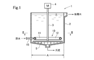
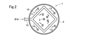
- FIG. 2 is a sectional view taken along line II-II in FIG.
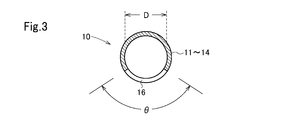
- FIG. 3 is a sectional view taken along line III-III in FIG. 2.
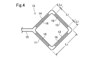
- It is a bottom view of a distributor. It is a bottom view of the distributor of the settling tank which concerns on another embodiment. It is a bottom view of the distributor of the settling tank which concerns on another embodiment. It is a bottom view of the distributor of the settling tank which concerns on another embodiment. It is a bottom view of the distributor of the settling tank which concerns on another embodiment. It is a bottom view of the distributor of the settling tank which concerns on another embodiment.
- the sedimentation tank 1 is arranged at a cylindrical tank body 2 with the axial direction as the vertical direction, a distributor 10 installed in the lower part (near the bottom) of the tank body 2, and the axial position of the tank body 2. And a drive device 4 having a motor for rotating the shaft 3, and a rake 5 (see FIG. 1; not shown in FIG. 2) attached to the lower end of the shaft 3.
- the distributor 10 has a square frame shape in plan view having a first side 11, a second side 12, a third side 13, and a fourth side 14 in this embodiment.
- the sides 11 to 14 are made of a cylindrical tube, and the inside is a flow path.
- a raw water introduction pipe 15 is connected to a portion where the first side 11 and the fourth side 14 are connected.
- the raw water introduction pipe 15 extends in the extension direction of the diagonal line of the square distributor 10.
- the outflow opening 16 extending in the longitudinal direction of each side 11 to 14 is provided on the bottom surface of each side 11 to 14 of the distributor 10.
- one opening 16 is provided on each side 11 to 14.
- Each opening 16 extends from the vicinity of one end of each of the sides 11 to 14 to the vicinity of the other end.
- the opening width of the opening 16 is uniform in the longitudinal direction of each side. Therefore, each opening 16 appears as an elongated rectangular shape in FIG. 4, which is a bottom view of the distributor 10. However, both ends in the longitudinal direction of the opening 16 may be rounded.
- Each side 11 to 14 of the distributor 10 consists of a straight cylindrical tube.
- the opening angle (opening angle in the width direction of the opening 16 with respect to the center of the tube) ⁇ of the bottom opening 16 is 60 ° to 180 °, preferably 90 ° to 150 °.
- L 1 is the tank body 2 of the diameter A of each side 11-14 of the distributor 10 is preferred.
- the length L 2 in the longitudinal direction of each opening 16 is L 1 -2L 3 .
- L 3 is preferably about 1 to 3 times, particularly about 1.2 to 2 times the inner diameter D of the tube.
- the specific gravity of the liquid in the precipitation tank 1 in the distributor 10 (the specific gravity of the sludge blanket when the sludge blanket layer is formed in the precipitation tank 1).
- the raw water having a specific gravity of 0.0001 to 0.1, in particular 0.0005 to 0.05, is introduced. This raw water flows along the ceiling surface in the distributor 10 and gradually flows out from the opening 16 into the sedimentation tank 1 along the way. Since the central angle ⁇ of the opening 16 is 60 to 180 °, preferably 90 to 150 °, sludge does not accumulate in the distributor 10, and the opening 16 is prevented from being blocked by sludge.
- the distributor 10 in the vicinity of the corner portion of the distributor 10 where the sides 11, 12, sides 12, 13, and sides 13, 14 intersect each other, the distributor 10 is bent by 90 °, and each corner portion, particularly the corner portion, In the vicinity of the downstream side, the flow in the distributor 10 is disturbed. Since the branch angle between the raw water introduction pipe 15 and the sides 11 and 14 is 45 °, the flow in the distributor 10 is disturbed in this vicinity, particularly on the downstream side. In this embodiment, since the range of the upstream and downstream sides respectively a distance L 3 from the corner portion is not provided with the opening 16, never raw water from Nearby flows out to the large amount of sedimentation tank 1.
- the bent portion refers to, for example, a portion where the flow path bends 45 ° or more during a flow path length of about 5 times or less of the tube inner diameter D, or a portion where such a branch is abruptly branched.
- the downstream side of the bent part means the downstream side of the branch part.
- the openings 16 are continuously provided in the longitudinal direction of the sides 11 to 14, but a plurality of openings 16 may be provided per side in an intermittent manner. Even in this case, the width of each opening is uniform in the longitudinal direction of the opening. Each opening is preferably provided at equal intervals on each side.
- the opening may be provided intermittently.
- the raw water introduction pipe 15 is connected to the portion where the sides 11 and 14 of the distributor 10 intersect, but the raw water introduction pipe 15 is connected to the middle of one side 11 as in the distributor 10A of FIG. May be. In this case, since the vicinity of the contact point between the raw water introduction pipe 15 and the side 11 corresponds to a bent portion, the opening 16 is not provided.
- a square annular tube 19 connected to the side 13 via the tube 18 in the distributor 10A in FIG. .
- An opening 16 is also provided on the lower surface of the rectangular annular tube 19. However, the opening 16 is not provided in the vicinity of the bent portion at the four corners of the rectangular annular tube 19 and in the vicinity of the connection portion of the tube 18.
- An opening 16 is provided on the entire bottom surface of the distributor 20 except for the vicinity of the connecting portion between the raw water introduction pipe 15 and the distributor 20.
- the 8 has three straight pipes 31, 32, 33 extending in three directions of radiation.
- One of the tubes 31 is shorter than the tubes 32 and 33.
- a raw water introduction pipe 15 is connected to the tip of the pipe 31.
- the angle with respect to the flowing water direction at the branch portion of the tubes 32 and 33 with respect to the tube 31 is 30 ° and less than 45 °, and therefore the portion where the tubes 31, 32 and 33 intersect does not correspond to the bent portion. Therefore, the opening 16 is provided on the entire bottom surface of the tubes 32 and 33.
- FIGS. 2, 5 and 8 are suitable because they are easy to manufacture.
- the distributors 10 and 10A shown in FIGS. 2 and 5 are preferable because the raw water easily flows out from the openings 16 evenly.
- Experiment 1 (Raw water runoff experiment with different distributor opening angle ⁇ )
- the distributor shown in FIG. 5 was installed at a height of 10 cm from the bottom of a sedimentation tank having a diameter of 150 cm and a water depth of 150 cm without an agitator installed outdoors.
- the outer diameter of the distributor is 114 mm
- the inner diameter of the pipe is 107 mm
- the length of each side 11 to 14 is 110 cm
- the length of the opening 16 of the sides 12 to 14 is 70 cm
- the length of the opening 16 of the side 11 is 20 cm. is there.
- the opening angle ⁇ of the opening 16 is as shown in Table 1.
- the material of the tube is vinyl chloride.
- the inside of the sedimentation tank below the distributor was divided into a base end side (raw water introduction pipe 15 side) and a front end side by a baffle plate so that it was possible to check whether the raw water was evenly supplied to the front side and the back side.
- Experiment 3 (Outflow experiment from a distributor with all openings 16 made continuous) In Example 3, all the openings 16 on each side of the distributor were made continuous. When raw water was supplied under the same conditions as in Example 3 except that this distributor was used, the outflow amount from the base end side was 25 m 3 / hr and the outflow amount from the front end side was 5 m 3 / hr. From the base end side, it flowed out significantly.
Landscapes
- Chemical & Material Sciences (AREA)
- Chemical Kinetics & Catalysis (AREA)
- Organic Chemistry (AREA)
- Life Sciences & Earth Sciences (AREA)
- Hydrology & Water Resources (AREA)
- Engineering & Computer Science (AREA)
- Environmental & Geological Engineering (AREA)
- Water Supply & Treatment (AREA)
- Feeding, Discharge, Calcimining, Fusing, And Gas-Generation Devices (AREA)
- Separation Of Suspended Particles By Flocculating Agents (AREA)
- Branch Pipes, Bends, And The Like (AREA)
Abstract
Description
上記実施の形態では、開口16は辺11~14の長手方向に連続して設けられているが、途切れ途切れに一辺当り複数個設けられてもよい。この場合でも、各開口の幅は開口長手方向において均一である。なお、各開口は各辺において等間隔に設けられることが好ましい。
屋外に設置した撹拌機を設けない直径150cm、水深150cmの沈殿槽の底部から10cmの高さに図5に示すディストリビュータを設置した。ディストリビュータの管外径は114mm、管内径は107mm、各辺11~14の長さは110cm、辺12~14の開口16の長さはそれぞれ70cm、辺11の開口16の長さはそれぞれ20cmである。開口16の開き角度θは表1の通りである。管の材質は塩化ビニルである。ディストリビュータより下方の沈殿槽内部を邪魔板によって基端側(原水導入管15側)と先端側とに区画し、原水が手前側と奥側とに均等に供給されているか確認できるようにした。

ディストリビュータとして図8に示すものを用いたこと以外は実施例3と同一条件として実験を行った(開き角度θも120°であり、実施例3と同一である。)。その結果、ディストリビュータ基端側からの流出量は4.5m3/hr、先端側からの流出量は25.5m3/hrであり、先端側から著しく多量に流出した。
実施例3において、ディストリビュータの各辺の開口16をすべて連続させて一続きとした。このディストリビュータを用いたこと以外は実施例3と同一条件にて原水を供給したところ、基端側からの流出量は25m3/hrであり、先端側からの流出量は5m3/hrであり、基端側から著しく多量に流出した。
本出願は、2012年11月20日付で出願された日本特許出願2012-254492に基づいており、その全体が引用により援用される。
Claims (6)
- 管状の通水部材と、該通水部材の底面に設けられ、通水部材の長手方向に延在する液流出用開口とを有するディストリビュータにおいて、
該通水部材の管軸に対する該開口の開き角度θが60~180°であることを特徴とするディストリビュータ。 - 請求項1において、該開き角度θが90~150°であることを特徴とするディストリビュータ。
- 請求項1又は2において、前記通水部材の流水方向が45°以上変化する屈曲部付近の少なくとも下流側では前記開口が不存在であることを特徴とするディストリビュータ。
- 槽体と、該槽体の下部に設置された請求項1ないし3のいずれか1項に記載のディストリビュータとを備え、
該ディストリビュータが前記開口を下方に向けて設置されている沈殿槽。 - 請求項4において、前記ディストリビュータの平面視形状が枠状又は環状であることを特徴とする沈殿槽。
- 請求項4又は5の沈殿槽を運転する方法であって、前記ディストリビュータに供給する液の比重d1と前記槽体内の液の比重d2との差が0.0001~0.1であり、かつd2>d1であることを特徴とする沈殿槽の運転方法。
Priority Applications (3)
| Application Number | Priority Date | Filing Date | Title |
|---|---|---|---|
| US14/441,381 US20150273362A1 (en) | 2012-11-20 | 2013-11-18 | Distributor, settling tank and method for operating same |
| CN201380060573.7A CN104797316A (zh) | 2012-11-20 | 2013-11-18 | 导水机构、沉淀槽及其运转方法 |
| SG11201503662RA SG11201503662RA (en) | 2012-11-20 | 2013-11-18 | Distributor, settling tank and method for operating same |
Applications Claiming Priority (2)
| Application Number | Priority Date | Filing Date | Title |
|---|---|---|---|
| JP2012-254492 | 2012-11-20 | ||
| JP2012254492A JP5799939B2 (ja) | 2012-11-20 | 2012-11-20 | ディストリビュータ、沈殿槽及びその運転方法 |
Publications (1)
| Publication Number | Publication Date |
|---|---|
| WO2014080855A1 true WO2014080855A1 (ja) | 2014-05-30 |
Family
ID=50776038
Family Applications (1)
| Application Number | Title | Priority Date | Filing Date |
|---|---|---|---|
| PCT/JP2013/080996 Ceased WO2014080855A1 (ja) | 2012-11-20 | 2013-11-18 | ディストリビュータ、沈殿槽及びその運転方法 |
Country Status (7)
| Country | Link |
|---|---|
| US (1) | US20150273362A1 (ja) |
| JP (1) | JP5799939B2 (ja) |
| KR (1) | KR20150086266A (ja) |
| CN (1) | CN104797316A (ja) |
| MY (1) | MY175482A (ja) |
| SG (1) | SG11201503662RA (ja) |
| WO (1) | WO2014080855A1 (ja) |
Cited By (1)
| Publication number | Priority date | Publication date | Assignee | Title |
|---|---|---|---|---|
| CN107088320A (zh) * | 2016-02-18 | 2017-08-25 | 克利尔科夫系统有限公司 | 用于增加通过污水处理系统的均匀出水流动的器械和方法 |
Families Citing this family (1)
| Publication number | Priority date | Publication date | Assignee | Title |
|---|---|---|---|---|
| CN108911316A (zh) * | 2018-09-03 | 2018-11-30 | 大渊环境技术(厦门)有限公司 | 一种等离子体脱氮装置及其使用方法 |
Citations (3)
| Publication number | Priority date | Publication date | Assignee | Title |
|---|---|---|---|---|
| JPS5418154A (en) * | 1977-07-08 | 1979-02-09 | Kubota Ltd | Concentrating device |
| JPS6138692A (ja) * | 1984-07-19 | 1986-02-24 | パーケス ビー.ブイ. | 中央給水系に接続される流入液分配装置を備えた上昇流型反応器より成る浄水装置 |
| JP2000334214A (ja) * | 1999-05-27 | 2000-12-05 | Kurita Water Ind Ltd | 凝集沈殿装置 |
Family Cites Families (17)
| Publication number | Priority date | Publication date | Assignee | Title |
|---|---|---|---|---|
| US1355073A (en) * | 1920-10-05 | brenkert | ||
| US1741187A (en) * | 1929-12-31 | Clarxfier | ||
| US2179246A (en) * | 1937-09-14 | 1939-11-07 | Permutit Co | Water treating apparatus |
| US2355305A (en) * | 1943-02-01 | 1944-08-08 | Socony Vacuum Oil Co Inc | Mill scale settling tank |
| US3814262A (en) * | 1972-10-12 | 1974-06-04 | Universal Oil Prod Co | Emulsion separation apparatus |
| FR2480617B1 (fr) * | 1980-04-21 | 1986-01-17 | Bardet Sa Ets Andre | Appareil et installation de separation de liquides non miscibles de densites differentes |
| CN1008357B (zh) * | 1984-07-19 | 1990-06-13 | 帕奎斯公司 | 含溶解物和/或分散物的厌氧净化水的设备 |
| US5478468A (en) * | 1993-09-10 | 1995-12-26 | Sumitomo Heavy Industries, Ltd. | Coagulating sedimentation processing apparatus |
| US5458777A (en) * | 1994-03-23 | 1995-10-17 | Shell Oil Company | Distributor for liquid separator |
| US5637234A (en) * | 1994-06-30 | 1997-06-10 | Mccasland; Edwin D. | Apparatus and method for separating fluids having different specific gravities, such as oil and water |
| JP3463493B2 (ja) * | 1997-01-17 | 2003-11-05 | 栗田工業株式会社 | 凝集沈殿装置 |
| ATE303191T1 (de) * | 1999-05-31 | 2005-09-15 | Sumitomo Heavy Industries | Vorrichtung für koagulierende sedimentation |
| JP4535419B2 (ja) * | 2001-05-31 | 2010-09-01 | オルガノ株式会社 | 凝集沈澱装置 |
| US6920984B2 (en) * | 2002-12-06 | 2005-07-26 | Warren Roy Agnew | Rainwater tank cleaning system |
| US7021471B2 (en) * | 2003-05-06 | 2006-04-04 | Hamilton Welding Company | Diffuser for an oil water separator system |
| EP2066421B1 (de) * | 2006-09-18 | 2016-02-10 | Sulzer Chemtech AG | Einrichtung zum erzeugen einer diskreten flüssigphase in einer kontinuierlichen flüssigphase |
| FI120930B (fi) * | 2008-09-19 | 2010-05-14 | Finnketju Invest Oy | Järjestely nesteenkäsittelytilassa |
-
2012
- 2012-11-20 JP JP2012254492A patent/JP5799939B2/ja active Active
-
2013
- 2013-11-18 CN CN201380060573.7A patent/CN104797316A/zh active Pending
- 2013-11-18 US US14/441,381 patent/US20150273362A1/en not_active Abandoned
- 2013-11-18 KR KR1020157012668A patent/KR20150086266A/ko not_active Ceased
- 2013-11-18 SG SG11201503662RA patent/SG11201503662RA/en unknown
- 2013-11-18 MY MYPI2015701484A patent/MY175482A/en unknown
- 2013-11-18 WO PCT/JP2013/080996 patent/WO2014080855A1/ja not_active Ceased
Patent Citations (3)
| Publication number | Priority date | Publication date | Assignee | Title |
|---|---|---|---|---|
| JPS5418154A (en) * | 1977-07-08 | 1979-02-09 | Kubota Ltd | Concentrating device |
| JPS6138692A (ja) * | 1984-07-19 | 1986-02-24 | パーケス ビー.ブイ. | 中央給水系に接続される流入液分配装置を備えた上昇流型反応器より成る浄水装置 |
| JP2000334214A (ja) * | 1999-05-27 | 2000-12-05 | Kurita Water Ind Ltd | 凝集沈殿装置 |
Cited By (1)
| Publication number | Priority date | Publication date | Assignee | Title |
|---|---|---|---|---|
| CN107088320A (zh) * | 2016-02-18 | 2017-08-25 | 克利尔科夫系统有限公司 | 用于增加通过污水处理系统的均匀出水流动的器械和方法 |
Also Published As
| Publication number | Publication date |
|---|---|
| JP2014100663A (ja) | 2014-06-05 |
| CN104797316A (zh) | 2015-07-22 |
| KR20150086266A (ko) | 2015-07-27 |
| MY175482A (en) | 2020-06-30 |
| SG11201503662RA (en) | 2015-06-29 |
| US20150273362A1 (en) | 2015-10-01 |
| JP5799939B2 (ja) | 2015-10-28 |
Similar Documents
| Publication | Publication Date | Title |
|---|---|---|
| US10463992B2 (en) | High-rate sedimentation tank and water treatment apparatus including the same | |
| JP5799940B2 (ja) | 沈殿槽及びその運転方法 | |
| CN209010206U (zh) | 絮凝沉淀装置以及污水处理系统 | |
| CN103922527A (zh) | 一体化污水深度处理装置及其工艺 | |
| WO2013003012A1 (en) | Improved dissolved air flotation system and method | |
| CN105008286A (zh) | 逆渗透膜装置的运转方法以及逆渗透膜装置 | |
| JP5799939B2 (ja) | ディストリビュータ、沈殿槽及びその運転方法 | |
| CN106563298A (zh) | 一种污水沉淀池 | |
| JP5851827B2 (ja) | 凝集沈殿装置 | |
| JP4635666B2 (ja) | 水処理方法 | |
| JP2012045498A (ja) | 濃縮装置 | |
| KR102541106B1 (ko) | 침전조 | |
| CN108046397B (zh) | 连续分离的污水处理用沉降槽 | |
| JP3195378U (ja) | テーパー形状を有する固液分離装置 | |
| CN211189390U (zh) | 一种生产用水循环系统的沉淀池 | |
| CN203095668U (zh) | 一种可自动加热及反洗的絮凝沉淀除油器 | |
| JP6617635B2 (ja) | 沈殿槽 | |
| CN105347563B (zh) | 一种气浮和过滤一体化装置 | |
| CN113457224A (zh) | 一种沉淀物分离器 | |
| JP7605090B2 (ja) | 水処理装置および水処理方法 | |
| JP2023076228A (ja) | 凝集沈殿処理方法、水処理方法、凝集沈殿装置、及び水処理装置 | |
| CN104787865B (zh) | 抛物线折流式防堵塞废水混凝加药系统 | |
| CN219823946U (zh) | 一种原水处理系统 | |
| CN206985804U (zh) | 一种快速高效沉淀一体机 | |
| WO2019009128A1 (ja) | 凝集沈澱装置、及び浄水処理システム |
Legal Events
| Date | Code | Title | Description |
|---|---|---|---|
| 121 | Ep: the epo has been informed by wipo that ep was designated in this application |
Ref document number: 13856991 Country of ref document: EP Kind code of ref document: A1 |
|
| WWE | Wipo information: entry into national phase |
Ref document number: 14441381 Country of ref document: US |
|
| ENP | Entry into the national phase |
Ref document number: 20157012668 Country of ref document: KR Kind code of ref document: A |
|
| WWE | Wipo information: entry into national phase |
Ref document number: IDP00201502952 Country of ref document: ID |
|
| NENP | Non-entry into the national phase |
Ref country code: DE |
|
| 122 | Ep: pct application non-entry in european phase |
Ref document number: 13856991 Country of ref document: EP Kind code of ref document: A1 |