WO2014080854A1 - 沈殿槽及びその運転方法 - Google Patents
沈殿槽及びその運転方法 Download PDFInfo
- Publication number
- WO2014080854A1 WO2014080854A1 PCT/JP2013/080995 JP2013080995W WO2014080854A1 WO 2014080854 A1 WO2014080854 A1 WO 2014080854A1 JP 2013080995 W JP2013080995 W JP 2013080995W WO 2014080854 A1 WO2014080854 A1 WO 2014080854A1
- Authority
- WO
- WIPO (PCT)
- Prior art keywords
- tank
- distributor
- tank body
- sludge
- stirring
- Prior art date
- Legal status (The legal status is an assumption and is not a legal conclusion. Google has not performed a legal analysis and makes no representation as to the accuracy of the status listed.)
- Ceased
Links
Images





Classifications
-
- B—PERFORMING OPERATIONS; TRANSPORTING
- B01—PHYSICAL OR CHEMICAL PROCESSES OR APPARATUS IN GENERAL
- B01D—SEPARATION
- B01D21/00—Separation of suspended solid particles from liquids by sedimentation
- B01D21/24—Feed or discharge mechanisms for settling tanks
- B01D21/2405—Feed mechanisms for settling tanks
-
- B—PERFORMING OPERATIONS; TRANSPORTING
- B01—PHYSICAL OR CHEMICAL PROCESSES OR APPARATUS IN GENERAL
- B01D—SEPARATION
- B01D21/00—Separation of suspended solid particles from liquids by sedimentation
- B01D21/24—Feed or discharge mechanisms for settling tanks
- B01D21/2405—Feed mechanisms for settling tanks
- B01D21/2416—Liquid distributors with a plurality of feed points
-
- B—PERFORMING OPERATIONS; TRANSPORTING
- B01—PHYSICAL OR CHEMICAL PROCESSES OR APPARATUS IN GENERAL
- B01D—SEPARATION
- B01D21/00—Separation of suspended solid particles from liquids by sedimentation
- B01D21/28—Mechanical auxiliary equipment for acceleration of sedimentation, e.g. by vibrators or the like
- B01D21/286—Means for gentle agitation for enhancing flocculation
-
- C—CHEMISTRY; METALLURGY
- C02—TREATMENT OF WATER, WASTE WATER, SEWAGE, OR SLUDGE
- C02F—TREATMENT OF WATER, WASTE WATER, SEWAGE, OR SLUDGE
- C02F1/00—Treatment of water, waste water, or sewage
-
- C—CHEMISTRY; METALLURGY
- C02—TREATMENT OF WATER, WASTE WATER, SEWAGE, OR SLUDGE
- C02F—TREATMENT OF WATER, WASTE WATER, SEWAGE, OR SLUDGE
- C02F1/00—Treatment of water, waste water, or sewage
- C02F1/006—Water distributors either inside a treatment tank or directing the water to several treatment tanks; Water treatment plants incorporating these distributors, with or without chemical or biological tanks
-
- C—CHEMISTRY; METALLURGY
- C02—TREATMENT OF WATER, WASTE WATER, SEWAGE, OR SLUDGE
- C02F—TREATMENT OF WATER, WASTE WATER, SEWAGE, OR SLUDGE
- C02F1/00—Treatment of water, waste water, or sewage
- C02F2001/007—Processes including a sedimentation step
Definitions
- the present invention relates to a sedimentation tank such as a coagulation sedimentation tank, and more particularly to a sedimentation tank having a sludge outlet on the side surface of the tank body.
- the present invention also relates to a method for operating the settling tank.
- sedimentation separation using a solid-liquid separation tank is generally employed as a means for separating the sludge mixture into treated water and sludge.
- a sludge blanket filtration system that forms a sludge zone (sludge blanket layer) in the sedimentation tank in order to efficiently remove turbidity and fine SS in the sludge mixture and obtain good treated water. Is adopted.
- Patent Documents 1 and 2 describe that floc-containing raw water is introduced from the inlet of one side surface of the tank body of the settling tank, and the concentrated sludge is discharged from the outlet of the other side surface portion of the tank body. Yes. Patent Document 2 describes that the inside of a tank is stirred with a stirring blade.
- Patent Document 3 a net-like body is horizontally installed near the middle stage of the tank body of the settling tank, the raw water containing flock is allowed to flow into the lower side of the net body, and a sludge blanket is formed on the upper side of the net-like body.
- Patent Document 3 describes that the sludge in the upper layer portion of the sludge blanket is caused to flow out from the outlet provided in the side surface portion of the tank body.
- Patent Document 4 describes that floc-containing raw water is discharged from a distributor into a tank body, sludge accumulated below a sludge blanket is collected by a rake provided on the lower side of the distributor, and concentrated sludge is taken out from the center of the bottom of the tank body. Has been.
- the side discharge system sedimentation tank that discharges the sludge of the upper sludge blanket from the tank body as shown in Patent Documents 1 to 3, has a sharp rise in the blanket interface. It has the advantage that the quality of treated water is not easily deteriorated.
- JP 2006-75750 A JP 2000-271407 A JP-A-2005-21118 JP 10-202009
- Patent Document 2 the inside of the tank is agitated, but in order to agitate the entire sludge blanket so that the diameter of the agitation blade is small and sufficient to prevent sludge deposition, the number of revolutions of the agitation blade is significantly increased. The floc is destroyed and the quality of the supernatant water is likely to deteriorate.
- Patent Document 3 since the floc-containing raw water is allowed to flow into the lower side of the mesh body, it is considered that the sludge blanket on the upper side of the mesh body is less likely to deposit than Patent Document 1.
- the reticulate body is easily clogged with flocs, and operation stability is poor.
- the raw water passes through the non-blocked portion and rises at a high flow rate, so that the sludge blanket is partially spouted and the sludge tends to be mixed into the supernatant water.
- the object of the present invention is to solve the above-mentioned conventional problems, to provide a sedimentation tank in which the quality of treated water is good and the operation is stable over a long period of time, and an operation method thereof.
- the precipitation tank of the present invention includes a tank body, a distributor for introducing raw water installed in a lower part of the tank body, a stirring body provided between the bottom surface of the tank body and the distributor, A sludge outlet provided above the distributor on the side, a sludge receiving chamber connected to the sludge outlet, and a sludge discharging portion provided in the sludge receiving chamber.
- the stirring body is installed so as to be able to turn right above the bottom surface of the tank body.
- the tank body is cylindrical, and the swirling diameter of the stirring body is 0.6 to 0.95 times the inner diameter (diameter) of the cylindrical tank body.
- the height of the bottom surface of the distributor with respect to the bottom surface of the tank body is preferably 1 to 30% of the height from the bottom surface of the tank body to the sludge outlet.
- the operation method of the settling tank of the present invention is a method of operating the settling tank, wherein the stirring strength (G value) of the stirring body in the space between the bottom surface of the tank body and the bottom surface of the distributor is 5. Stirring is carried out so that the pressure becomes ⁇ 200 s ⁇ 1 .
- the distributor has a horizontal tubular portion, horizontal to the bottom surface of the tubular portion are longitudinally liquid outlet opening is extended, the tank body of the liquid specific gravity d 1 and the supply to the distributor
- the difference from the specific gravity d 2 is preferably 0.0001 to 0.1, and d 2 > d 1 is preferable.
- the floc-containing raw water is introduced from the distributor to the lower part or the bottom of the tank body, and is stirred by the stirring body to grow the floc, and this floc (sludge) is received from the outlet on the tank body side. And is discharged from the sludge discharge section of the receiving chamber.
- this stirring body since this stirring body is disposed between the distributor and the bottom surface of the tank body, sludge accumulation and retention at the bottom of the tank body is prevented. For this reason, it is prevented that sludge stays in a tank body bottom part over a long period of time and rots or ferments. For this reason, the rise of sludge due to adhesion of methane gas, hydrogen sulfide gas or the like is prevented, and the quality of the treated water is improved over a long period.
- the tank body is cylindrical, and the swirling diameter of the stirring body is increased to 0.6 to 0.95 times the inner diameter (diameter) of the tank body, so that sludge can be more reliably prevented from remaining on the entire bottom surface of the tank body. .
- the height of the distributor bottom surface
- the installation height of the stirring body below the distributor is also lowered, and sludge retention near the bottom of the tank body is more reliably prevented.
- the distributor has a horizontal tubular portion, and a liquid outflow opening is extended in the longitudinal direction on the bottom surface of the horizontal tubular portion.
- raw water treated liquid
- the specific gravity of the liquid in the sedimentation tank especially the specific gravity of the sludge blanket layer
- the raw water has its specific gravity. Since the liquid is smaller than the liquid in the tank, it flows in the distributor in the longitudinal direction along the ceiling surface in the distributor, and gradually flows into the precipitation tank through the opening in the middle. Since the opening of the distributor is provided on the bottom surface of the distributor, the sludge flows out from the opening into the sedimentation tank without accumulating in the distributor.
- FIG. 2 is a sectional view taken along line II-II in FIG.
- FIG. 3 is a sectional view taken along line III-III in FIG. 2.
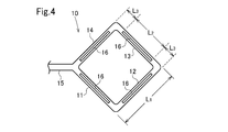
- It is a bottom view of a distributor. It is a bottom view of the distributor of the settling tank which concerns on another embodiment. It is a bottom view of the distributor of the settling tank which concerns on another embodiment. It is a bottom view of the distributor of the settling tank which concerns on another embodiment. It is a bottom view of the distributor of the settling tank which concerns on another embodiment. It is a bottom view of the distributor of the settling tank which concerns on another embodiment. It is a graph which shows the result of an Example.
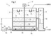
- the sedimentation tank 1 includes a cylindrical tank body 2 with the axial direction as a vertical direction, a distributor 10 installed in a lower part (near the bottom) in the tank body 2, and an intermediate part between the side surfaces of the tank body 2. Or an outlet 3 provided at a slightly higher position, a receiving tank 4 communicating with the tank body 2 through the outlet 3, an agitator 5 provided in the tank body 2, and a tank body 2 has a treated water (supernatant water) extraction trough 6 provided at an upper portion in 2, a sludge discharge port 7 for taking out the concentrated sludge from the lower portion of the receiving tank 4, and the like.
- the inside of the receiving tank 4 is the receiving chamber 4a.
- the stirrer 5 is attached to a drive unit 5a such as a motor, a rotary shaft 5b that is vertically disposed in the axial center of the tank body 2, and rotated by the drive unit 5a, and a lowermost end of the rotary shaft. It has the 1st stirring body 5c and the 2nd and 3rd stirring bodies 5d and 5e attached higher than it.
- the third stirring body 5e is provided above the second stirring body 5d.
- each of the stirring members 5c to 5e is a paddle blade composed of blades extending in the radial direction from the rotating shaft 5b.
- the stirring members 5c to 5e extend in the four directions of radiation, but may be in two or more directions of radiation.
- the stirring body 5c is disposed below the distributor 10, and the stirring bodies 5d and 5e are disposed above the distributor 10.
- the uppermost stirring body 5e is positioned below the lower edge of the outlet 3.
- Turning diameter D 2 of the stirrer 5c ⁇ 5e is 0.6-0.95 times the inner diameter (diameter) D 1 tank body 2 which is preferably 0.8 to 0.95.
- H 1 The height from the bottom surface of the tank body 2 to the lower edge of the outlet 3 is H 1
- H 2 the height from the bottom surface of the tank body 2 to the bottom surface of the stirring body 5c
- H 2 is preferably not more than 5% of H 1, and more preferably 3% or less.
- H 2 is preferably 10 mm or more.
- the height H 4 from the bottom surface of the distributor 10 to the top surface of the stirring member 5c is preferably 20% or less of H 3 , and more preferably 10% or less.
- H 4 is preferably 10 mm or more.
- the distributor 10 has a square frame shape in plan view having a first side 11, a second side 12, a third side 13, and a fourth side 14 in this embodiment.
- the sides 11 to 14 are made of a cylindrical tube, and the inside is a flow path.
- a raw water introduction pipe 15 is connected to a portion where one end of the first side 11 and one end of the fourth side 14 are connected.
- the raw water introduction pipe 15 extends in the extension direction of the diagonal line of the square distributor 10.
- the outflow opening 16 extending in the longitudinal direction of each side 11 to 14 is provided on the bottom surface of each side 11 to 14 of the distributor 10.
- one opening 16 is provided on each side 11 to 14.
- Each opening 16 extends from the vicinity of one end of each of the sides 11 to 14 to the vicinity of the other end.
- the opening width of the opening 16 is uniform in the longitudinal direction of each side. Therefore, each opening 16 appears as an elongated rectangular shape in FIG. 4, which is a bottom view of the distributor 10. However, both ends in the longitudinal direction of the opening 16 may be rounded.
- Each side 11 to 14 of the distributor 10 consists of a straight cylindrical tube.
- the opening angle (opening angle in the width direction of the opening 16 with respect to the center of the tube) ⁇ of the bottom opening 16 is 60 ° to 180 °, preferably 90 ° to 150 °.
- the total length L 1 of each side 11 to 14 of the distributor 10 is preferably about 50 to 90%, particularly about 60 to 80% of the diameter D 1 of the tank body 2.
- the length L 2 in the longitudinal direction of each opening 16 is (L 1 ⁇ 2 ⁇ L 3 ). In the vicinity of the corner where the sides 11 to 14 of the distributor 10 are connected to each other, the opening 16 does not exist over the range of the distance L 3 from the tip of each side 11 to 14.
- L 3 is preferably about 1 to 3 times, particularly about 1.2 to 2 times the inner diameter (diameter) D of the tube.
- the specific gravity of the liquid in the precipitation tank 1 in the distributor 10 (the specific gravity of the sludge blanket when the sludge blanket layer is formed in the precipitation tank 1).
- the raw water having a specific gravity of 0.0001 to 0.1, in particular 0.0005 to 0.05, is introduced. This raw water flows along the ceiling surface in the distributor 10 and gradually flows out from the opening 16 into the sedimentation tank 1 along the way. Since the central angle ⁇ of the opening 16 is 60 to 180 °, preferably 90 to 150 °, sludge does not accumulate in the distributor 10, and the opening 16 is prevented from being blocked by sludge.
- the distributor 10 in the vicinity of the corner portion of the distributor 10 where the sides 11, 12, sides 12, 13, and sides 13, 14 intersect each other, the distributor 10 is bent by 90 °, and in the vicinity of each corner portion, particularly in the corner portion.
- the flow in the distributor 10 is disturbed on the downstream side. Since the branch angle between the raw water introduction pipe 15 and the sides 11 and 14 is 45 °, the flow in the distributor 10 is disturbed in this vicinity, particularly on the downstream side.
- the range of the upstream and downstream sides respectively a distance L 3 from the corner portion is not provided with the opening 16, never raw water from Nearby flows out to the large amount of sedimentation tank 1.
- the bent portion refers to, for example, a portion where the flow path bends 45 ° or more during a flow path length of about 5 times or less of the tube inner diameter D, or a portion where such a branch is abruptly branched.
- the downstream side of the bent part means the downstream side of the branch part.
- the raw water supplied from the distributor 10 into the tank body 2 is stirred by the stirring bodies 5c to 5e and is turbidized when passing through the sludge blanket S to become treated water.
- the treated water flows out from the trough 6. Since the suspended substance is adsorbed by the flocs in the sludge blanket S, the interface of the blanket S gradually rises. When the interface reaches the height of the outlet 3, the flock in the blanket S flows out from the outlet 3 to the receiving chamber 4a.
- the sludge that is stored and concentrated in the receiving chamber 4a is taken out from the discharge port 7.
- the stirring by the stirring body 5c is preferably such that the stirring strength in the space from the bottom surface of the tank body 2 to the bottom surface of the distributor 10 is 5 to 200 s ⁇ 1, particularly 20 to 120 s ⁇ 1 in terms of G value.
- G value the average speed gradient value represented by the following equation is used as an indicator of the stirring intensity of the stirring and mixing by the stirring blades, and is determined by the size, the number of sheets, and the number of rotations of the stirring blades.
- the stirring by the stirring bodies 5e and 5d is preferably such that the stirring intensity in the space from the distributor 10 to the lower edge of the outlet 3 is 1 to 80 s ⁇ 1 , particularly 2 to 30 s ⁇ 1 in terms of G value. Agitation at this agitation strength promotes floc growth of the sludge blanket layer.
- the ascending linear velocity in the tank body 2 is 5 to 60 m / hr, particularly 7 to 20 m / hr.
- the openings 16 are continuously provided in the longitudinal direction of the sides 11 to 14, but a plurality of openings 16 may be provided per side in an intermittent manner. Even in this case, the width of each opening is uniform in the longitudinal direction of the opening. Each opening is preferably provided at equal intervals on each side.
- the opening may be provided intermittently.
- the raw water introduction pipe 15 is connected to the portion where the sides 11 and 14 of the distributor 10 intersect, but the raw water introduction pipe 15 is connected to the middle of one side 11 as in the distributor 10A of FIG. May be.
- the opening 16 is not provided in the vicinity of the connecting portion between the raw water introduction pipe 15 and the side 11.
- a square annular tube 19 connected to the side 13 via the tube 18 in the distributor 10A in FIG. .
- An opening 16 is also provided on the lower surface of the rectangular annular tube 19. However, the opening 16 is not provided in the vicinity of the bent portion at the four corners of the rectangular annular tube 19 and in the vicinity of the connection portion of the tube 18.
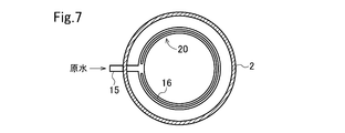
- An opening 16 is provided on the entire bottom surface of the distributor 20 except for the vicinity of the contact point between the raw water introduction pipe 15 and the distributor 20.
- the 8 has three straight pipes 31, 32, 33 extending in three directions of radiation.
- One of the tubes 31 is shorter than the tubes 32 and 33.
- a raw water introduction pipe 15 is connected to the tip of the pipe 31.
- the crossing angle of the tubes 32 and 33 is 60 °. Since the angle with respect to the flowing water direction in the branch part of the pipes 32 and 33 with respect to the pipe 31 is 30 ° and less than 45 °, the portion intersecting the pipes 31, 32 and 33 does not correspond to the bent portion. Therefore, the opening 16 is provided on the entire bottom surface of the tubes 32 and 33.
- FIGS. 2, 5 and 8 are suitable because they are easy to manufacture.
- the distributors 10 and 10A shown in FIGS. 2 and 5 are preferable because the raw water easily flows out from the openings 16 evenly.
- Example 1 The raw water having the following water quality was treated using the apparatus shown in FIGS. ⁇ Raw water quality> SS concentration: 100 mg / L pH: 7.3 Specific gravity difference from the solution in the tank: 0.017 ⁇ Structure of sedimentation tank> Size: 1500mm diameter, 1500mm height Horizontal length of stirring blade: 1.35m (0.9 times the inner diameter of the tank) H 1 : 0.8 m H 2 : 0.03 m (4% of H 1 ) H 3 : 0.09 m (11% of H 1 ) H 4 : 0.015 m (17% of H 3 ) ⁇ Chemicals and amount used> Sulfuric acid band: 300 mg / L Cationic polymer: 1 mg / L (Kurita Industry Co., Ltd.
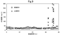
- Example 1 As shown in FIG. 9, treated water of 50 mg / L or less was stably obtained in Example 1 for 2 days continuously, whereas Comparative Example 1 was deposited on the bottom after about 38 hours and 43 hours. The bubbles accumulated in the sludge that had been formed, and the sludge mass floated, and the quality of the treated water deteriorated to 300 mg / L. From this, it was recognized that stable treated water can be obtained by stirring the sludge under the distributor as in Example 1.
Landscapes
- Chemical & Material Sciences (AREA)
- Chemical Kinetics & Catalysis (AREA)
- Life Sciences & Earth Sciences (AREA)
- Hydrology & Water Resources (AREA)
- Engineering & Computer Science (AREA)
- Environmental & Geological Engineering (AREA)
- Water Supply & Treatment (AREA)
- Organic Chemistry (AREA)
- Mixers Of The Rotary Stirring Type (AREA)
- Feeding, Discharge, Calcimining, Fusing, And Gas-Generation Devices (AREA)
- Separation Of Suspended Particles By Flocculating Agents (AREA)
- Mixers With Rotating Receptacles And Mixers With Vibration Mechanisms (AREA)
Abstract
Description
G=√(g・w/μ)
g:重力加速度(=9.8)(m/s2)
w:単位時間、単位容積当たりの仕事量(kg・m/m3・s)
μ:水の粘性係数(kg/m・s)
この撹拌強度で撹拌を行うと、槽体2の底面付近での汚泥の滞留が防止される。
上記実施の形態のディストリビュータ10では、開口16は辺11~14の長手方向に連続して設けられているが、途切れ途切れに一辺当り複数個設けられてもよい。この場合でも、各開口の幅は開口長手方向において均一である。なお、各開口は各辺において等間隔に設けられることが好ましい。
下記の構成を有する図1~4に示す装置を用い、下記水質の原水を処理した。
<原水水質>
SS濃度:100mg/L
pH:7.3
槽内液との比重差:0.017
<沈殿槽の構造>
サイズ:直径1500mm、高さ1500mm
撹拌羽根の水平長さ:1.35m(槽内径の0.9倍)
H1:0.8m
H2:0.03m(H1の4%)
H3:0.09m(H1の11%)
H4:0.015m(H3の17%)
<薬品及び使用量>
硫酸バンド:300mg/L
カチオンポリマー:1mg/L(栗田工業株式会社製クリファームPC728)
アニオンポリマー:3mg/L(栗田工業株式会社製クリファームPA465)
<運転条件>
通水LV:15m/hr
撹拌強度(G値):
ディストリビュータ上面から流出口下端までの領域に対して30s-1
ディストリビュータ下面と槽底部の空間に対して88s-1
処理水のSS濃度の経時変化を図9に示す。
撹拌装置5を設けないこと以外は実施例1と同一の装置を用い、同一条件にて原水を処理した。処理水のSS濃度の経時変化を図9に示す。
図9に示す通り、実施例1では2日間連続して50mg/L以下の処理水を安定的に
得られたのに対し、比較例1では、約38時間及び43時間経過後に、底部に堆積していた汚泥内に気泡が溜まることにより、汚泥塊の浮上が起こり、処理水質が300mg/Lまで悪化した。このことから、実施例1のようにディストリビュータ下の汚泥を撹拌することにより、安定した処理水が得られることが認められた。
本出願は、2012年11月20日付で出願された日本特許出願2012-254493に基づいており、その全体が引用により援用される。
Claims (6)
- 槽体と、
該槽体内の下部に設置された原水導入用のディストリビュータと、
該槽体の底面と該ディストリビュータとの間に設けられた撹拌体と、
該槽体の側部の該ディストリビュータよりも上位に設けられた汚泥流出口と、
該汚泥流出口に連なる汚泥受入室と、
該汚泥受入室に設けられた汚泥排出部と
を有する沈殿槽。 - 請求項1において、前記撹拌体は前記槽体の底面の直上に旋回可能に設置されていることを特徴とする沈殿槽。
- 請求項2において、前記槽体は円筒形であり、前記撹拌体の旋回直径は円筒形槽体の内径(直径)の0.6~0.95倍であることを特徴とする沈殿槽。
- 請求項2又は3において、前記槽体の底面からの前記ディストリビュータの底面までの高さH3は、該槽体底面から前記汚泥流出口までの高さH1の1~30%であることを特徴とする沈殿槽。
- 請求項1ないし4のいずれか1項の沈殿槽を運転する方法であって、前記槽体の底面と前記ディストリビュータの底面との間のスペースにおける前記撹拌体の撹拌強度(G値)が5~200s-1となるように撹拌を行うことを特徴とする沈殿槽の運転方法。
- 請求項5において、前記ディストリビュータは水平管状部を有しており、該水平管状部の底面に長手方向に液流出用開口が延設されており、
該ディストリビュータに供給する液の比重d1と前記槽体内の液の比重d2との差が0.0001~0.1であり、かつd2>d1であることを特徴とする沈殿槽の運転方法。
Priority Applications (3)
| Application Number | Priority Date | Filing Date | Title |
|---|---|---|---|
| US14/441,408 US9649578B2 (en) | 2012-11-20 | 2013-11-18 | Settling tank and method of operating the same |
| SG11201503663SA SG11201503663SA (en) | 2012-11-20 | 2013-11-18 | Settling tank and method of operating the same |
| CN201380060580.7A CN104812456B (zh) | 2012-11-20 | 2013-11-18 | 沉淀槽及其运转方法 |
Applications Claiming Priority (2)
| Application Number | Priority Date | Filing Date | Title |
|---|---|---|---|
| JP2012-254493 | 2012-11-20 | ||
| JP2012254493A JP5799940B2 (ja) | 2012-11-20 | 2012-11-20 | 沈殿槽及びその運転方法 |
Publications (1)
| Publication Number | Publication Date |
|---|---|
| WO2014080854A1 true WO2014080854A1 (ja) | 2014-05-30 |
Family
ID=50776037
Family Applications (1)
| Application Number | Title | Priority Date | Filing Date |
|---|---|---|---|
| PCT/JP2013/080995 Ceased WO2014080854A1 (ja) | 2012-11-20 | 2013-11-18 | 沈殿槽及びその運転方法 |
Country Status (7)
| Country | Link |
|---|---|
| US (1) | US9649578B2 (ja) |
| JP (1) | JP5799940B2 (ja) |
| KR (1) | KR20150086265A (ja) |
| CN (1) | CN104812456B (ja) |
| MY (1) | MY168521A (ja) |
| SG (1) | SG11201503663SA (ja) |
| WO (1) | WO2014080854A1 (ja) |
Cited By (3)
| Publication number | Priority date | Publication date | Assignee | Title |
|---|---|---|---|---|
| CN106267918A (zh) * | 2016-09-06 | 2017-01-04 | 云南文山铝业有限公司 | 净水装置 |
| CN108531369A (zh) * | 2018-07-10 | 2018-09-14 | 湖北景源生物科技股份有限公司 | 一种用于木薯生产酒精的高温厌氧罐进料装置 |
| CN108531370A (zh) * | 2018-07-10 | 2018-09-14 | 湖北景源生物科技股份有限公司 | 一种用于木薯生产酒精的高温厌氧罐 |
Families Citing this family (6)
| Publication number | Priority date | Publication date | Assignee | Title |
|---|---|---|---|---|
| JP5900576B1 (ja) * | 2014-10-24 | 2016-04-06 | 栗田工業株式会社 | 水処理方法及び水処理装置 |
| JP6459716B2 (ja) * | 2015-03-31 | 2019-01-30 | 住友重機械エンバイロメント株式会社 | 凝集沈殿処理装置 |
| JP6582888B2 (ja) * | 2015-11-02 | 2019-10-02 | 栗田工業株式会社 | 凝集沈殿装置 |
| JP6183525B1 (ja) * | 2016-09-23 | 2017-08-23 | 栗田工業株式会社 | 凝集沈澱装置 |
| CN110382074B (zh) | 2017-02-24 | 2021-08-24 | 奥加诺株式会社 | 絮凝和沉积设备 |
| JP7025158B2 (ja) * | 2017-02-24 | 2022-02-24 | オルガノ株式会社 | 凝集沈殿装置 |
Citations (3)
| Publication number | Priority date | Publication date | Assignee | Title |
|---|---|---|---|---|
| JPS5418154A (en) * | 1977-07-08 | 1979-02-09 | Kubota Ltd | Concentrating device |
| JP2000334214A (ja) * | 1999-05-27 | 2000-12-05 | Kurita Water Ind Ltd | 凝集沈殿装置 |
| JP2005211817A (ja) * | 2004-01-30 | 2005-08-11 | Japan Organo Co Ltd | 高濃度懸濁水の処理方法および装置 |
Family Cites Families (14)
| Publication number | Priority date | Publication date | Assignee | Title |
|---|---|---|---|---|
| US1741187A (en) * | 1929-12-31 | Clarxfier | ||
| US3038608A (en) * | 1958-10-13 | 1962-06-12 | Infilco Inc | Liquid treating process and apparatus |
| US3129066A (en) * | 1961-04-18 | 1964-04-14 | Rohm & Haas | Mixer-settler apparatus |
| FR2132954A5 (ja) * | 1971-04-02 | 1972-11-24 | Degremont | |
| FR2480617B1 (fr) * | 1980-04-21 | 1986-01-17 | Bardet Sa Ets Andre | Appareil et installation de separation de liquides non miscibles de densites differentes |
| NL8402281A (nl) * | 1984-07-19 | 1986-02-17 | Pacques Bv | Inrichting voor de zuivering van water, voorzien van een opstroomreactor met een op het centrale watertoevoersysteem aan te sluiten influentverdeelsysteem. |
| US5075001A (en) * | 1989-07-13 | 1991-12-24 | Taylor James W | Method and apparatus for recovering fibrous material from a paper/pulp process water stream |
| US5478468A (en) * | 1993-09-10 | 1995-12-26 | Sumitomo Heavy Industries, Ltd. | Coagulating sedimentation processing apparatus |
| JP3463493B2 (ja) | 1997-01-17 | 2003-11-05 | 栗田工業株式会社 | 凝集沈殿装置 |
| JP3866439B2 (ja) | 1999-03-26 | 2007-01-10 | オルガノ株式会社 | 凝集沈澱装置 |
| ATE303191T1 (de) * | 1999-05-31 | 2005-09-15 | Sumitomo Heavy Industries | Vorrichtung für koagulierende sedimentation |
| JP4535419B2 (ja) * | 2001-05-31 | 2010-09-01 | オルガノ株式会社 | 凝集沈澱装置 |
| UA78727C2 (en) * | 2001-11-09 | 2007-04-25 | Alcan Int Ltd | Settler and method for decanting mineral slurries |
| JP2006075750A (ja) | 2004-09-10 | 2006-03-23 | Japan Organo Co Ltd | 凝集分離処理装置及び凝集分離処理方法 |
-
2012
- 2012-11-20 JP JP2012254493A patent/JP5799940B2/ja active Active
-
2013
- 2013-11-18 SG SG11201503663SA patent/SG11201503663SA/en unknown
- 2013-11-18 MY MYPI2015701482A patent/MY168521A/en unknown
- 2013-11-18 CN CN201380060580.7A patent/CN104812456B/zh not_active Expired - Fee Related
- 2013-11-18 WO PCT/JP2013/080995 patent/WO2014080854A1/ja not_active Ceased
- 2013-11-18 KR KR1020157012667A patent/KR20150086265A/ko not_active Ceased
- 2013-11-18 US US14/441,408 patent/US9649578B2/en not_active Expired - Fee Related
Patent Citations (3)
| Publication number | Priority date | Publication date | Assignee | Title |
|---|---|---|---|---|
| JPS5418154A (en) * | 1977-07-08 | 1979-02-09 | Kubota Ltd | Concentrating device |
| JP2000334214A (ja) * | 1999-05-27 | 2000-12-05 | Kurita Water Ind Ltd | 凝集沈殿装置 |
| JP2005211817A (ja) * | 2004-01-30 | 2005-08-11 | Japan Organo Co Ltd | 高濃度懸濁水の処理方法および装置 |
Cited By (3)
| Publication number | Priority date | Publication date | Assignee | Title |
|---|---|---|---|---|
| CN106267918A (zh) * | 2016-09-06 | 2017-01-04 | 云南文山铝业有限公司 | 净水装置 |
| CN108531369A (zh) * | 2018-07-10 | 2018-09-14 | 湖北景源生物科技股份有限公司 | 一种用于木薯生产酒精的高温厌氧罐进料装置 |
| CN108531370A (zh) * | 2018-07-10 | 2018-09-14 | 湖北景源生物科技股份有限公司 | 一种用于木薯生产酒精的高温厌氧罐 |
Also Published As
| Publication number | Publication date |
|---|---|
| CN104812456B (zh) | 2016-08-17 |
| US20150298028A1 (en) | 2015-10-22 |
| JP2014100664A (ja) | 2014-06-05 |
| MY168521A (en) | 2018-11-12 |
| KR20150086265A (ko) | 2015-07-27 |
| CN104812456A (zh) | 2015-07-29 |
| JP5799940B2 (ja) | 2015-10-28 |
| SG11201503663SA (en) | 2015-06-29 |
| US9649578B2 (en) | 2017-05-16 |
Similar Documents
| Publication | Publication Date | Title |
|---|---|---|
| JP5799940B2 (ja) | 沈殿槽及びその運転方法 | |
| KR102034148B1 (ko) | 응집 농축 기능이 포함된 심층구조의 슬러지 수집기 및 이를 포함하는 고탁도 폐수처리시스템 | |
| US20010019027A1 (en) | Solid-liquid separator | |
| CN104781198B (zh) | 包括与重力过滤相结合的浮选的水处理方法以及相应设备 | |
| AU2012225140B2 (en) | Reactor for precipitating solutes from wastewater and associated methods | |
| KR100808289B1 (ko) | 스크류형 경사판을 갖는 폐수설비의 침전조 | |
| JP6067268B2 (ja) | 水処理システム | |
| KR101450772B1 (ko) | 침전조 장치 | |
| CN108203196A (zh) | 一种城市污水处理净化装置 | |
| KR102541106B1 (ko) | 침전조 | |
| CN204490579U (zh) | 一种污水斜管沉淀装置 | |
| KR20090030617A (ko) | 개선된 센터웰 장치가 포함된 수처리용 침전조 | |
| JP2022105223A (ja) | 水処理槽の更新方法 | |
| JP5799939B2 (ja) | ディストリビュータ、沈殿槽及びその運転方法 | |
| KR20060093997A (ko) | 스크류형 경사판을 갖는 폐수설비의 침전조 | |
| CN221286970U (zh) | 一种基于多孔溢流管的沉淀系统 | |
| CA2932166C (en) | Filtering system for removing chemicals from fluids | |
| WO2015041676A1 (en) | A precipitation tank and method of use | |
| CN111792801A (zh) | 膜浓缩浓水结晶器及反渗透浓水处理装置 | |
| KR20010088734A (ko) | 침전 여과조와, 이를 이용한 오수처리장치 및 방법 | |
| JP7605090B2 (ja) | 水処理装置および水処理方法 | |
| CN101239258A (zh) | 污泥漏斗悬浮泥渣层式斜板沉淀工艺与装置 | |
| CN101244347A (zh) | 污泥漏斗悬浮泥渣层式斜板、斜管沉淀工艺与装置 | |
| CN212269812U (zh) | 膜浓缩浓水结晶器及反渗透浓水处理装置 | |
| JP2006272253A (ja) | 沈殿槽 |
Legal Events
| Date | Code | Title | Description |
|---|---|---|---|
| 121 | Ep: the epo has been informed by wipo that ep was designated in this application |
Ref document number: 13857069 Country of ref document: EP Kind code of ref document: A1 |
|
| WWE | Wipo information: entry into national phase |
Ref document number: 14441408 Country of ref document: US |
|
| ENP | Entry into the national phase |
Ref document number: 20157012667 Country of ref document: KR Kind code of ref document: A |
|
| NENP | Non-entry into the national phase |
Ref country code: DE |
|
| 122 | Ep: pct application non-entry in european phase |
Ref document number: 13857069 Country of ref document: EP Kind code of ref document: A1 |