WO2014080658A1 - 電磁誘導式位置検出器の検出位置補正方法 - Google Patents
電磁誘導式位置検出器の検出位置補正方法 Download PDFInfo
- Publication number
- WO2014080658A1 WO2014080658A1 PCT/JP2013/066433 JP2013066433W WO2014080658A1 WO 2014080658 A1 WO2014080658 A1 WO 2014080658A1 JP 2013066433 W JP2013066433 W JP 2013066433W WO 2014080658 A1 WO2014080658 A1 WO 2014080658A1
- Authority
- WO
- WIPO (PCT)
- Prior art keywords
- detection position
- coil
- constant speed
- section
- detection
- Prior art date
- Legal status (The legal status is an assumption and is not a legal conclusion. Google has not performed a legal analysis and makes no representation as to the accuracy of the status listed.)
- Ceased
Links
Images

Classifications
-
- G—PHYSICS
- G01—MEASURING; TESTING
- G01D—MEASURING NOT SPECIALLY ADAPTED FOR A SPECIFIC VARIABLE; ARRANGEMENTS FOR MEASURING TWO OR MORE VARIABLES NOT COVERED IN A SINGLE OTHER SUBCLASS; TARIFF METERING APPARATUS; MEASURING OR TESTING NOT OTHERWISE PROVIDED FOR
- G01D5/00—Mechanical means for transferring the output of a sensing member; Means for converting the output of a sensing member to another variable where the form or nature of the sensing member does not constrain the means for converting; Transducers not specially adapted for a specific variable
- G01D5/12—Mechanical means for transferring the output of a sensing member; Means for converting the output of a sensing member to another variable where the form or nature of the sensing member does not constrain the means for converting; Transducers not specially adapted for a specific variable using electric or magnetic means
- G01D5/14—Mechanical means for transferring the output of a sensing member; Means for converting the output of a sensing member to another variable where the form or nature of the sensing member does not constrain the means for converting; Transducers not specially adapted for a specific variable using electric or magnetic means influencing the magnitude of a current or voltage
- G01D5/20—Mechanical means for transferring the output of a sensing member; Means for converting the output of a sensing member to another variable where the form or nature of the sensing member does not constrain the means for converting; Transducers not specially adapted for a specific variable using electric or magnetic means influencing the magnitude of a current or voltage by varying inductance, e.g. by a movable armature
-
- G—PHYSICS
- G01—MEASURING; TESTING
- G01D—MEASURING NOT SPECIALLY ADAPTED FOR A SPECIFIC VARIABLE; ARRANGEMENTS FOR MEASURING TWO OR MORE VARIABLES NOT COVERED IN A SINGLE OTHER SUBCLASS; TARIFF METERING APPARATUS; MEASURING OR TESTING NOT OTHERWISE PROVIDED FOR
- G01D5/00—Mechanical means for transferring the output of a sensing member; Means for converting the output of a sensing member to another variable where the form or nature of the sensing member does not constrain the means for converting; Transducers not specially adapted for a specific variable
- G01D5/12—Mechanical means for transferring the output of a sensing member; Means for converting the output of a sensing member to another variable where the form or nature of the sensing member does not constrain the means for converting; Transducers not specially adapted for a specific variable using electric or magnetic means
- G01D5/244—Mechanical means for transferring the output of a sensing member; Means for converting the output of a sensing member to another variable where the form or nature of the sensing member does not constrain the means for converting; Transducers not specially adapted for a specific variable using electric or magnetic means influencing characteristics of pulses or pulse trains; generating pulses or pulse trains
- G01D5/24471—Error correction
- G01D5/24476—Signal processing
-
- G—PHYSICS
- G01—MEASURING; TESTING
- G01D—MEASURING NOT SPECIALLY ADAPTED FOR A SPECIFIC VARIABLE; ARRANGEMENTS FOR MEASURING TWO OR MORE VARIABLES NOT COVERED IN A SINGLE OTHER SUBCLASS; TARIFF METERING APPARATUS; MEASURING OR TESTING NOT OTHERWISE PROVIDED FOR
- G01D5/00—Mechanical means for transferring the output of a sensing member; Means for converting the output of a sensing member to another variable where the form or nature of the sensing member does not constrain the means for converting; Transducers not specially adapted for a specific variable
- G01D5/12—Mechanical means for transferring the output of a sensing member; Means for converting the output of a sensing member to another variable where the form or nature of the sensing member does not constrain the means for converting; Transducers not specially adapted for a specific variable using electric or magnetic means
- G01D5/244—Mechanical means for transferring the output of a sensing member; Means for converting the output of a sensing member to another variable where the form or nature of the sensing member does not constrain the means for converting; Transducers not specially adapted for a specific variable using electric or magnetic means influencing characteristics of pulses or pulse trains; generating pulses or pulse trains
- G01D5/24471—Error correction
- G01D5/24495—Error correction using previous values
Definitions
- the present invention relates to a detection position correction method for an electromagnetic induction type position detector which is a linear scale or a rotary scale.
- Induct thin type scale which is an electromagnetic induction type position detector, is applied to position detection in various machines such as machine tools, automobiles and robots.
- Induct thin type scales include linear scales and rotary scales.
- a linear scale is installed on a moving body such as a table of a machine tool and detects a linear movement position of the moving body.
- a rotary scale is mounted on a moving body (rotating body) such as a rotary table of a machine tool. It is installed and detects the rotational position (rotational angle) of the moving body (rotating body).
- Both the linear scale and the rotary scale detect the position by electromagnetic induction of coil patterns arranged so as to face each other in parallel. This detection principle will be described based on the principle diagram of FIG.
- FIG. 6A is a perspective view showing a state in which a slider and a scale of a linear scale are arranged so as to face each other in parallel
- FIG. 6B is a view showing the slider and the scale side by side
- FIG. c) is a diagram showing the degree of electromagnetic coupling between the slider and the scale.
- the detection principle of the rotary scale is the same as that of the linear scale, and the stator and rotor of the rotary scale correspond to the slider and scale of the linear scale.
- Each of the linear type scale and the rotary type scale has a detection unit and a detection control device.
- the linear scale detector 10 includes a slider 1 as a primary member and a scale 2 as a secondary member.
- the slider 1 is a movable part, and has a first slider coil 3 that is a first primary coil and a second slider coil 4 that is a second primary coil.
- the scale 2 is a fixed part and has a scale coil 5 that is a secondary coil.
- the coils 3, 4 and 5 are folded back in a zigzag shape (comb pattern) and formed so as to be linear as a whole.
- the slider 1 is attached to a moving body such as a table of a machine tool and moves linearly with the moving body.
- the scale 2 is fixed to a fixed part such as a bed of a machine tool.
- the slider 1 (first slider coil 3 and second slider coil 4) and the scale 2 (scale coil 5) hold a predetermined gap g between them. Are arranged so that they face each other in parallel. Further, as shown in FIGS. 6A and 6B, the first slider coil 3 and the second slider coil 4 are shifted by 1 ⁇ 4 pitch.
- a first excitation current Ia as shown in the following equation (1) is passed through the first slider coil 3 and a second as shown in the following equation (2).
- the exciting current Ib is passed through the second slider coil 4.
- Ia ⁇ Icos (k ⁇ ) sin ( ⁇ t) (1)
- Ib Isin (k ⁇ ) sin ( ⁇ t) (2)
- I magnitude of excitation current k: 2 ⁇ / p p: coil pitch (length: angle for rotary scale)
- ⁇ angular frequency of excitation current (alternating current)
- t time
- ⁇ excitation position
- V KIsin (k (X ⁇ )) sin ( ⁇ t) (3)
- K Transmission coefficient depending on gap g and angular frequency ⁇ of exciting current
- X Detection position (moving position of moving body)
- an error of the coil pitch period (an error that periodically fluctuates according to the period of the coil pitch) that appears prominently as an error included in the detection position X is referred to as an interpolation error.
- a high-accuracy position detector different from the electromagnetic induction position detector is used, and the detection position of the high-accuracy position detector and the detection position X of the electromagnetic induction position detector are used.
- a method of acquiring correction data based on the above is conceivable.
- this method requires preparation of a high-accuracy position detector, which increases cost and labor.
- the present invention has been made in view of the above circumstances, and does not require a high-accuracy position detector different from the electromagnetic induction position detector, and obtains correction data by the electromagnetic induction position detector itself. It is an object of the present invention to provide a detection position correction method for an electromagnetic induction type position detector capable of correcting a detection position.
- the detection position correction method of the electromagnetic induction type position detector of the first invention that solves the above-described problem is A primary side member having a primary side coil and a secondary side member having a secondary side coil, and the primary side member or the secondary side member is attached to a movable body and moves together with the movable body.
- a detection position correction method of an electromagnetic induction type position detector arranged so that the primary side coil and the secondary side coil are parallel and face each other, A detection position acquisition process in which the moving body is moved by a speed command value of a constant speed, and the position of the moving body is detected by the electromagnetic induction type position detector to acquire a detection position; Based on the detection position and the coil pitch of the secondary coil, or based on the detection position, the constant speed, and the moving time of the moving body, or the coil pitch of the secondary coil and the constant speed And a constant speed determination process for determining that the mobile body has moved at the constant speed in a predetermined movement section based on the movement time of the mobile body; A detection position corresponding to the start position of any one of the coil pitches in the moving section is set as a reference detection position, and a product of an elapsed time after obtaining the reference detection position and the constant speed is set as the reference detection position.
- An approximate ideal position is obtained by addition, and correction data acquisition processing for acquiring correction data based on the approximate ideal position and
- the detection position correction method of the electromagnetic induction type position detector of the second invention is the detection position correction method of the electromagnetic induction type position detector of the first invention
- the moving section is a section corresponding to n times the coil pitch p (n is a natural number)
- the moving time required for the moving body to move in the moving section at the constant speed S is T 1
- the detection position corresponding to the start position of the movement section is X (t 0 )
- the detection position corresponding to the end position of the movement section is X (t 0 + T 1 )
- If the threshold is ⁇ L
- n * p ⁇ L ⁇ X (t 0 + T 1 ) ⁇ X (t 0 ) ⁇ n * p + L it is determined that the moving body has moved at the constant speed S in the moving section.
- the detection position correction method of the electromagnetic induction type position detector of the third invention is the detection position correction method of the electromagnetic induction type position detector of the first invention.
- the moving section is a section corresponding to n times the coil pitch p (n is a natural number)
- the moving time required for the moving body to move in the moving section at the constant speed S is T 1
- the detection position corresponding to the start position of the movement section is X (t 0 )
- the detection position corresponding to the end position of the movement section is X (t 0 + T 1 )
- If the threshold is ⁇ L
- S * T 1 ⁇ L ⁇ X (t 0 + T 1 ) ⁇ X (t 0 ) ⁇ S * T 1 + L it is determined that the moving body has moved at the constant speed S in the moving section. It is characterized by that.
- the detection position correction method of the electromagnetic induction type position detector of the fourth invention is the detection position correction method of the electromagnetic induction type position detector of the first invention.
- the moving section is a section corresponding to n times the coil pitch p (n is a natural number)
- T 2 is a movement time determined by the mobile body to have traveled the moving section
- If the threshold is ⁇ L, When the condition of n * p ⁇ L ⁇ S * T 2 ⁇ n * p + L is satisfied, it is determined that the moving body has moved at the constant speed S in the moving section.
- a detection position correction method for an electromagnetic induction position detector is the detection position correction method for an electromagnetic induction position detector according to any one of the first to fourth aspects of the invention.
- the time when the detection position corresponding to the starting end position of any coil pitch p in the moving section is acquired is t 0
- the time when the detection position corresponding to the terminal position of any other coil pitch p in the movement section is acquired is defined as t 0 + T.
- a detection position corresponding to the start position of any coil pitch p in the movement section is set as a reference detection position X (t 0 ),
- a detection position correction method for an electromagnetic induction type position detector comprising: A plurality of the movement sections are provided, correction data is acquired in the plurality of movement sections, and an average value of the plurality of correction data is used as final correction data.
- the primary side member includes a primary side member provided with a primary side coil and a secondary side member provided with a secondary side coil.
- an electromagnetic induction type position detector in which the secondary side member is attached to a moving body and moves together with the moving body, and the primary side coil and the secondary side coil are arranged in parallel to face each other.
- a detection position correction method wherein the moving body is moved by a speed command value at a constant speed, and the position of the moving body is detected by the electromagnetic induction type position detector to obtain a detection position; and Based on the detection position and the coil pitch of the secondary coil, or based on the detection position, the constant speed, and the moving time of the moving body, or the coil pitch of the secondary coil and the constant speed And the above Based on the movement time of the body, a constant speed determination process for determining that the moving body has moved at the constant speed in a predetermined movement section, and a detection position corresponding to the start position of any coil pitch in the movement section Is used as a reference detection position, and an approximate ideal position is obtained by adding, to the reference detection position, a product of an elapsed time since the acquisition of the reference detection position and the constant speed, and the approximate ideal position and the detection position.
- correction data acquisition processing that acquires correction data based on the above, it does not require a high-accuracy position detector different from the electromagnetic induction position detector, and the electromagnetic induction position detector itself Thus, correction data can be acquired and the detection position can be corrected.
- the moving section is defined as the coil.
- An interval corresponding to n times the pitch p (n is a natural number) is set, and the moving time required for the moving body to move in the moving interval at the constant speed S is T 1.
- the electromagnetic induction position detector itself Makes it easy and reliable to determine the constant speed of a moving object. I can.
- the moving section is defined as the coil.
- An interval corresponding to n times the pitch p (n is a natural number) is set, and the moving time required for the moving body to move in the moving interval at the constant speed S is T 1.
- the moving section is defined as the coil.
- the pitch p n is a natural number
- the moving time it is determined that required for moving the moving section and T 2
- the threshold value ⁇ L, n * When the condition of p ⁇ L ⁇ S * T 2 ⁇ n * p + L is satisfied, it is determined that the moving body has moved at the constant speed S in the moving section, so that the electromagnetic induction position detector itself
- the condition of p ⁇ L ⁇ S * T 2 ⁇ n * p + L it is determined that the moving body has moved at the constant speed S in the moving section, so that the electromagnetic induction position detector itself
- the detection position correction method of the electromagnetic induction type position detector of the fifth invention in the detection position correction method of any one of the first to fourth inventions, in the correction data acquisition process,
- the detection position corresponding to the start position of any coil pitch p in the moving section is the reference detection position X (t 0 )
- the reference detection position X (t 0 ) is
- ⁇ t is fixed and the index number m is associated with t (m), or
- ⁇ x is fixed
- the detection position correction method of the electromagnetic induction type position detector of the sixth aspect of the invention in the detection position correction method of any one of the first to fifth aspects of the invention, a plurality of the movement sections are provided, Since the correction data is acquired in the plurality of movement sections and the average value of the plurality of correction data is used as the final correction data, correction data with higher accuracy can be acquired.
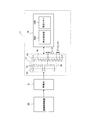
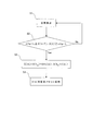
- FIG. 1 It is a figure which shows the structure of the system which implements the detection position correction method of the electromagnetic induction type position sensor which concerns on Example 1 of this invention. It is a flowchart which shows the process sequence of the said detection position correction method.
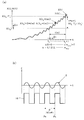
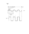
- (A) is a graph showing the change over time of the detection position including the error and the change over time of the ideal position, and (b) is a graph showing the change over time of the error included in the detection position.
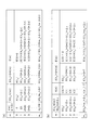
- (A) is a table showing the correspondence when ⁇ t is fixed and the index number m is associated with t (m), and (b) is the index number m and X (t 0 + t ( It is a table
- (A) is a perspective view showing a state in which a slider of a linear scale and the scale face each other in parallel
- (b) is a diagram showing the slider and the scale side by side
- (c) is an electromagnetic of the slider and the scale. It is a figure which shows a coupling
- Embodiment 1 A detection position correction method for an electromagnetic induction type position detector according to Embodiment 1 of the present invention will be described with reference to FIGS.
- the system shown in FIG. 1 has an electromagnetic induction position detector 11, a drive control device 20, and a moving body 21.
- the moving body 21 is a moving body that moves linearly, such as a table of a machine tool.
- the drive control device 20 includes a feed mechanism unit that linearly moves the moving body 21 (for example, a feed mechanism unit that includes a motor, a ball screw, and the like), and a drive control unit that controls driving of the mobile body 21 by the feed mechanism unit. Etc.
- the electromagnetic induction position detector 11 includes a detection unit 17 and a detection control device 18. Although the case where the electromagnetic induction type position detector 11 is a linear scale will be described here, the present invention can also be applied to the case where the electromagnetic induction type position detector 11 is a rotary type scale.
- the detection control device 18 includes a detection control unit 18A and a fixed memory 18B.
- the detection control unit 18A performs supply of excitation current to the detection unit 17, processing of a detection signal (induced voltage) of the detection unit 17, and the like.
- the fixed memory 18B is a type of memory (RAM, ROM) that retains stored data even when power supply to the fixed memory 18B is stopped.
- the configuration of the detection unit 17 of the electromagnetic induction type position detector 11 (linear scale) and the basic operation of the detection control device 18 (detection control unit 18A) are the same as those in the past.
- the detection unit 17 includes a slider 12 that is a primary side member and a scale 15 that is a secondary side member.
- the slider 12 is a movable part, and includes a first slider coil 13 that is a first primary coil and a second slider coil 14 that is a second primary coil.
- the scale 15 is a fixed part and has a scale coil 16 that is a secondary coil.
- the coils 13, 14, and 16 are folded back in a zigzag shape (comb pattern), and are formed to be linear as a whole.
- the slider 12 is attached to the moving body 21 and moves linearly with the moving body 12.
- the scale 12 is fixed to a fixed part such as a bed of a machine tool.
- the slider 12 (first slider coil 13 and second slider coil 14) and the scale 15 (scale coil 16) face each other in parallel with a predetermined gap g held between them. Are arranged (see FIG. 6A). Further, the first slider coil 13 and the second slider coil 14 are shifted by 1 ⁇ 4 pitch.
- the electromagnetic induction type position detector 11 having such a configuration, when an exciting current (alternating current) is passed through the first slider coil 13 and the second slider coil 14, the first slider coil 13 and the second slider coil 13 are moved along with the movement of the slider 12.
- an exciting current alternating current
- the degree of electromagnetic coupling between the first slider coil 13 and the second slider coil 14 and the scale coil 16 changes periodically (FIG. 6 (c)). For this reason, an induced voltage that periodically changes is generated in the scale coil 16.
- a first excitation current Ia as shown in the following equation (11) is passed through the first slider coil 13, and a second excitation current as shown in the following equation (12) is used. Ib flows through the second slider coil 14.
- Ia ⁇ Icos (k ⁇ ) sin ( ⁇ t) (11)
- Ib Isin (k ⁇ ) sin ( ⁇ t) (12)
- I magnitude of excitation current k: 2 ⁇ / p p: coil pitch (length: angle for rotary scale)
- ⁇ angular frequency of excitation current (alternating current)
- t time
- ⁇ excitation position
- V KIsin (k (X ⁇ )) sin ( ⁇ t) (13)
- K Transmission coefficient depending on gap g and angular frequency ⁇ of exciting current
- X Detection position (moving position of moving body)
- the actual electromagnetic induction type position detector 11 has a manufacturing error and an assembly error. Therefore, the above expression (13) is not satisfied, and the detection position X has an error E.
- a detection position acquisition process is performed in step S1.
- the moving body 21 (slider 12) is moved according to the speed command value of the constant speed S, and the position of the moving body 21 (slider 12) is detected by the electromagnetic induction position detector 11 to detect the detection position X.
- This detection position X can be expressed as X (t) as a function of time t during which the moving body 21 (slider 12) moves.
- a constant speed determination process is performed in step S2.
- the moving body 21 (slider 12) accelerates to the constant speed S and then moves to the vicinity of the target position at the constant speed S. Then, the vehicle decelerates and stops at the target position.
- the vehicle decelerates and stops at the target position.
- step S2 As a result of the constant speed determination process in step S2, if the mobile body 21 (slider 12) cannot be determined to move at the constant speed S in the moving section due to some problem (No), the problem is After the cancellation, the detection position acquisition process in step S1 and the constant speed determination process in step S2 are executed again. On the other hand, as a result of the constant speed determination process in step S2, if it is determined that the moving body 21 has moved at the constant speed S in the moving section (Yes), a correction data acquisition process is performed in the next step S3.
- a detection position corresponding to the start position of any one of the coil pitches p in the moving section is set as a reference detection position, and an elapsed time after acquiring this reference detection position is multiplied by a constant speed S.
- An approximate ideal position (position close to the ideal position) is obtained by adding the value to the reference detection position, and correction data is acquired based on the approximate ideal position and the detection position.
- step S4 the acquired correction data is stored in the fixed memory 18B.
- Detection position acquisition processing In order to acquire the detection position X (t), the moving body 21 (slider 12) is moved at a constant speed S. Specifically, a constant speed S as a speed command value and a target position are given to the drive control device 20.
- the drive control device 20 starts the moving body 21 (slider 12) by controlling the driving of the moving body 21 (slider 12) by the feed mechanism based on the speed command value of the constant speed S and the target position. After accelerating until reaching a constant speed S, it is moved to the vicinity of the target position at the constant speed S, and then decelerated and stopped at the target position. At this time, the detection control unit 18A of the detection control device 18 obtains the detection position X (t).
- the detection position X (t) is accompanied by an error E.
- the horizontal axis is time t
- the vertical axis is X (t), Xi (t).
- FIG. 3A shows the change over time of the detection position X (t) including the error E and the ideal.
- the position (true position) Xi (t) with time is shown.
- 3B the horizontal axis represents time t
- the vertical axis represents error E.
- FIG. 3B shows the change over time of the error E included in the detection position X (t), and the coil of the scale coil 16. It is shown corresponding to the pattern.
- the error E is a period corresponding to the coil pitch period of the scale coil 16 as illustrated in FIG. Fluctuates. Therefore, the detection position X (t) including the error E also periodically varies according to the coil pitch period of the scale coil 16 as illustrated in FIG. Note that in order to clearly show that the frequency fluctuates periodically according to the coil pitch cycle, the error E is represented by a sine wave in FIG. 3, but the actual error E has a slightly distorted waveform.
- the starting position of the coil pitch p means the starting position (starting point) p S in each coil pitch p of the scale coil 16 shown in FIG. 3B, and the end position of the coil pitch p.
- Constant speed determination process A constant speed determination process is performed using the detection position X (t) acquired in the detection position acquisition process. This constant speed determination process is performed by a first constant speed determination method, a second constant speed determination method, or a third constant speed determination method as described below.
- the detected position X (t) at time t 0 is X (t 0 ).
- the detection position X (t) at time t 0 + T 1 is assumed to be X (t 0 + T 1 ).
- a moving time required for the moving body 21 (slider 12) to move at a constant speed S and in a predetermined moving section that is n times the coil pitch p (n is a natural number) is T 1 .
- the movement amount is a movement distance (in the case of a rotary scale, it is a rotation angle).
- the moving time T 1 is a predetermined time set in advance, is determined by a constant speed S, a coil pitch p, and a coil pitch number n, and can be calculated by the equation n * p / S.
- * means the symbol x of multiplication (the same applies to other described portions, and the same applies to claims and drawings).
- the coil pitch p is, for example, 2 mm in the case of a linear scale (for example, 2 degrees in the case of a rotary scale).
- the coil pitch number n is, for example, 256 pitches.
- the predetermined movement section (section corresponding to n times the coil pitch p) is, for example, from the 101st coil pitch p of the scale coil 16 to the 356th scale coil 16 (when the coil pitch number n is 256).
- the section is set up to the coil pitch p.
- the detection position X (t 0 ) is a detection position corresponding to the start position of the predetermined movement section (section corresponding to n times the coil pitch p).
- the start position of the predetermined movement section (section corresponding to n times the coil pitch p) corresponds to the start position of the first (first) coil pitch p in the movement section.
- the detection position X (t 0 + T 1 ) is a detection position corresponding to the end position of the predetermined movement section (section corresponding to n times the coil pitch p).
- the end position of the predetermined movement section (section corresponding to n times the coil pitch p) corresponds to the end position of the last (nth: 256th) coil pitch p in the movement section.
- the start position of the predetermined movement section (section corresponding to n times the coil pitch p) is the first (1 ) Coil position p in the middle (position between the start position and end position of the coil pitch p), and the end position of the predetermined movement section (section corresponding to n times the coil pitch p) is It may be an intermediate position (position between the start end position and the end position of the coil pitch p) of the last (nth: 256th) coil pitch p in the movement section.
- a predetermined moving section (a section corresponding to n times the coil pitch p) in which it is determined that the moving body 21 (slider 12) has moved at a constant speed S is a start position of the first (first) coil pitch p.
- a start position of the first (first) coil pitch p is a start position of the first (first) coil pitch p.
- the last (nth: for example, 256th) coil pitch p from the middle position of the first (first) coil pitch p. It may be a section up to the middle position.
- the amount of movement X (t 0 + T 1) -X (t 0) is the closer to the ideal shift amount n * p, the detection position X (t 0) from the detection position X (t 0 + T 1) to section, i.e. It can be determined that the moving body 21 (slider 12) has moved at a constant speed S in the predetermined movement section (section corresponding to n times the coil pitch p). Times such as t 0 and T 1 can be measured by the number of clock counts provided in the detection control unit 18A of the detection control device 18 (may be measured by other time measurement means).
- the detection position at time t 0 + T 1 X (t 0 + T 1) is able to know the detection control unit 18A.
- the coil pitch p and the coil pitch number n are known values.
- the moving body 21 (slider 12) in the predetermined moving section (section corresponding to n times the coil pitch p) when the following expression (22) is satisfied. Can be determined to have moved at a constant speed S. Note that the relationship between X (t 0 + T 1 ) ⁇ X (t 0 ) and n * p ⁇ L is also illustrated in FIG. n * p ⁇ L ⁇ X (t 0 + T 1 ) ⁇ X (t 0 ) ⁇ n * p + L (22)
- the amount of movement X (t 0 + T 1) -X (t 0) is the ideal moving amount S * the closer to T 1, the detection position from the detection position X (t 0) X (t 0 + T 1) to section, That is, it can be determined that the moving body 21 (slider 12) has moved at a constant speed S in the predetermined movement section (section corresponding to n times the coil pitch p).
- the detection position X (t 0 ) corresponding to the start position of the predetermined movement section (section corresponding to n times the coil pitch p) and the detection position X (t 0 ) are acquired.
- the detection position at time t 0 + T 1 X (t 0 + T 1) is able to know the detection control unit 18A.
- the constant speed S and the movement time T 1 are known values.
- the detection position X (t) at time t 0 is assumed to be X (t 0 ).
- the detection position X (t) at time t 0 + T 1 is assumed to be X (t 0 + T 2 ).
- T 2 be the movement time when it is determined that the moving body 21 (slider 12) needs to move in a predetermined movement section that is n times the coil pitch p (n is a natural number).
- n is a natural number.
- the movement amount is a movement distance (in the case of a rotary scale, it is a rotation angle).
- the moving time T 2 is different from the above-mentioned fixed moving time T 1, and the moving body 21 (slider 12) moves in the predetermined moving section (a section corresponding to n times the coil pitch p).
- This time is determined to be necessary, and varies depending on the magnitude of the error included in the detection positions X (t 0 ) and X (t 0 + T 2 ).
- the coil pitch p is, for example, 2 mm in the case of a linear scale (for example, 2 degrees in the case of a rotary scale).
- the coil pitch number n is, for example, 256 pitches.
- the predetermined moving section (section corresponding to n times the coil pitch p) is, for example, the coil from the 101st coil pitch p of the scale coil 16 to the 356th scale coil 16 (when the coil pitch number n is 256). Set as interval up to pitch p.
- the movement time T 2 is the same as the constant movement time T 1, and thus the detection position X (t 0 ).
- S * T 2 and n * p are equal if the moving body 21 (slider 12) moves at a constant speed S in the section from the detection position X (t 0 + T 2 ) to the detection position X (t 0 + T 2 ).
- the detection positions X (t 0 ) and X (t 0 + T 2 ) include errors, and the movement time T 2 at this time is not the same as the constant movement time T 1 .
- the relationship between the movement amount S * T 2 and the ideal movement amount n * p is also expressed by the following equation (26).
- the above equation (25) is used to determine the constant speed.
- the relationship of the above equation (26) can be used. That is, if S * T 2 is close to n * p, it corresponds to a section from the detection position X (t 0 ) to the detection position X (t 0 + T 2 ), that is, the predetermined movement section (n times the coil pitch p). It is possible to determine that the moving body 21 (slider 12) has moved at a constant speed S in the section to be moved.
- Times such as t 0 and T 2 can be measured by the clock count provided in the detection control unit 18A of the detection control device 18 (may be measured by other time measurement means). Therefore, after obtaining the detection position X (t 0 ) corresponding to the start position of the predetermined movement section (section corresponding to n times the coil pitch p), the predetermined movement section (n times the coil pitch p) is obtained. Elapsed time (moving time) until the detection position X (t 0 + T 2 ) corresponding to the end position of the moving position (slider 12) is obtained in the predetermined moving section (coil pitch p). The movement time T 2 that is determined to have been required to move in the section corresponding to n times the number can be detected by the detection control unit 18A.
- the constant speed S, the coil pitch p, and the coil pitch number n are known values.
- the moving body 21 moves at a constant speed in the predetermined moving section (a section corresponding to n times the coil pitch p) when the condition of the following expression (27) is satisfied. It can be judged that it moved by S. n * p ⁇ L ⁇ S * T 2 ⁇ n * p + L (27)
- the moving body 21 is fixed by a constant speed determination process (a first constant speed determination method, a second constant speed determination method, or a third constant speed determination method).
- a constant speed determination process a first constant speed determination method, a second constant speed determination method, or a third constant speed determination method.
- the detection position X (t 0 ) is a detection position corresponding to the start position of the predetermined movement section (section corresponding to n times the coil pitch p), and the predetermined movement section (coil pitch p of the coil pitch p).
- the start position of the section corresponding to n times corresponds to the start position of the first (first) coil pitch p in the movement section, and corresponds to the predetermined movement section (n times the coil pitch p).
- correction data E (m) is acquired using the detected position data acquired in the section) as a whole will be described.
- the time when the detection position corresponding to the start position of the first (first) coil pitch p in the predetermined movement section (section corresponding to n times the coil pitch p) is acquired is t 0 .
- the time when the detection position corresponding to the terminal position of the last (nth: 256th, for example) coil pitch p in the predetermined movement section (section corresponding to n times the coil pitch p) is acquired as t 0 + T.
- the time T is the movement time T 1 or T 2 described in the constant speed determination process (the first constant speed determination method, the second constant speed determination method, or the third constant speed determination method).
- the detection position X (t 0 ) corresponding to the start position of the first (first) coil pitch p in the predetermined movement section (section corresponding to n times the coil pitch p) is set as a reference detection position.
- the index number m is associated with time t (m) or detection position X (t 0 + t (m)).
- X (t 0 ) + S * t (m) is a value close to the ideal position Xi (t 0 + t (m)).
- a position X (t 0 ) + S * t (m) close to the ideal position Xi (t 0 + t (m)) is referred to as an approximate ideal position.
- the correction data at the index number m is E (m).
- the ideal correction data E (m) can be obtained by subtracting the detected position X (t 0 + t (m)) from the ideal position Xi (t 0 + t (m)) as shown in the following equation (29). .
- the ideal position Xi (t 0 + t (m)) corresponding to the detected position X (t 0 + t (m)) cannot be known.
- E (m) Xi (t 0 + t (m)) ⁇ X (t 0 + t (m)) (29)
- X (t 0 ) is the detected position data acquired in the detected position acquisition process. Since the constant speed S and the time t (m) are known values, they can be calculated based on them.
- X (t 0 ) + S * t (m) and X (t 0 + t (m)) are obtained corresponding to the index number m, and these X (t 0 ) + S * t (m) and X (
- the correction data E (m) is calculated from the above equation (30) using t 0 + t (m)).
- the index number m is fixed with ⁇ t fixed as described above.
- X (t 0 ) + S * t (m) and X (X) are associated with the index number m by a method of associating the index number m with the time t (m) with ⁇ t fixed.
- An example when t 0 + t (m)) is obtained is shown.
- T is obtained by m * ⁇ t. That is, the time t 0 when the detection position X (t 0 ) is acquired is set as the reference time (0), and the time ⁇ t, 2 * ⁇ t, 3 * ⁇ t, every time ⁇ t time elapses from the reference time (0). ..., obtained as T.
- X (t 0 + t (m)) X (t 0 ), X (t 0 + ⁇ t), X (t 0 + 2 * ⁇ t), X (t 0 + 3 * ⁇ t),..., X (t 0 + T ) Is the detected position X (t 0 ) obtained at time t 0 , and thereafter the detected position X (t 0 + ⁇ t), X (t 0 + 2 * ⁇ t), X (t 0 +3) every time ⁇ t time elapses. * ⁇ t),..., X (t 0 + T).
- T is the time t when the detection position X (t 0 ) is acquired.
- the detection position X (t 0 ) + ⁇ x, X (t 0 ) + 2 * ⁇ x, X (t 0 ) + 3 * ⁇ x,. 0 ) + m m * ⁇ x is obtained as times t (1), t (2), t (3),.
- E (0) ( 0)
- E (1), E (2), E (3), .., E (m m ) are stored in order from the head address to each address of the fixed memory 18B. In this way, if the correction data E (m) is stored in order from the head address of the fixed memory 18B, it is not necessary to store the index number m.
- the address of the fixed memory 18B is the predetermined moving section (the section corresponding to n times the coil pitch p) from which the detected position data used for calculating the correction data E (m) is acquired. ) Corresponding to each coil pitch position from the start end position of the first (first) coil pitch p to the end position of the last (nth) coil pitch p. That is, the first address corresponds to the start position of the first (first) coil pitch p, and the m m + 1st address corresponds to the end position of the last (nth) coil pitch p, from the second to m m th. Address sequentially corresponds to each coil pitch position from the start position of the first (first) coil pitch p to the end position of the last (n-th) coil pitch p.
- the present invention is not necessarily limited to this, and the correction data E (m) may be stored at random in the address of the fixed memory 18B.
- the index number m is also stored in the fixed memory 18B, and the index number m and the correction data E (m) may be associated with each other.
- the index number 2 and the correction data E (2) may be stored at the fifth address
- the index number 3 and the correction data E (3) may be stored at the second address.
- the number of correction data E (m) stored in the fixed memory 18B is, for example, when the number of correction data E (m) per coil pitch p is 512 and the coil pitch number n is 256, There will be 131072.
- the predetermined moving section (the section corresponding to n times the coil pitch p) for acquiring the detection position data is made one, but the present invention is not limited to this, and the detection position data is acquired.
- detection position data is acquired in a plurality of movement sections (sections corresponding to n times the coil pitch p) by the same method as described above, and each movement section (coil pitch) is obtained based on these detection position data.
- correction data E (m) for each section is obtained, and an average value of the correction data E (m) for each of these movement sections (section corresponding to n times the coil pitch p) is obtained.
- the final correction data E (m) is used.
- the final (average value) correction data E (m) is stored in the fixed memory 18B. Also in this case, the method for storing the correction data E (m) in the fixed memory 18B is as described above.
- the detection control device 18 detects the detection position when the movable body 21 (slider 12) is moved to perform actual work (for example, machining with a machine tool).
- correction data E (m) is read from the fixed memory 18B.
- the detection position X (t 0 + t (m )) X by adding the correction data obtained E (m) read from the fixed memory 18B to '(t 0 + t (m ) ), And this X ′ (t 0 + t (m)) is output as a corrected detection position.
- X ′ (t 0 + t (m)) X (t 0 + t (m)) + E (m) (31)
- the detection control device 18 detects the position of the moving body 21 (slider 12) and obtains a certain detection position X (t)
- the detection position X (t) is It can be seen which coil pitch position corresponds to the detection position.
- the detection control device 18 detects the position of the moving body 21 (slider 12) and obtains a certain detection position X (t)
- the coil pitch position corresponding to a certain detection position X (t) corresponds to the coil pitch position corresponding to the first correction data E (m) and the second correction data E (m) next thereto.
- the first correction data E (m) for example, correction data E (10)
- the second correction data E (m) for example, correction data E (11)
- the corrected detection position is obtained by adding the correction data subjected to the interpolation to the detection position X (t).
- the correction data E (m) for the n coil pitches p acquired by the correction data acquisition process is repeatedly used for every n coil pitches p of the scale coil 16 to correct the detection position X (t).
- the coil pitch n may be one. That is, the correction data E (m) may be acquired for at least one coil pitch p. In this case, the correction data E (m) for one coil pitch p is repeatedly used for each coil pitch p of the scale coil 16 to correct the detection position X (t).
- the correction data E (m) is obtained using the detection position data in the predetermined movement section (section corresponding to n times the coil pitch p) as a whole, the present invention is not limited to this, and the detection position X ( The correction data E (m) may be obtained using a part of the data of t). That is, from the data of the detection position X (t N1 ) corresponding to the start position of an arbitrary N 1 th (for example, 50th) coil pitch p in the predetermined movement section (section corresponding to n times the coil pitch p).
- the correction data E (m) may be obtained by using it.
- the detection position X (t N1 ) becomes the reference detection position X (t 0 ), and the detection position X (t N2 ) becomes X (t 0 + t (m m )). Also in this case, the correction data E (m) can be acquired by the same method as described above.
- the predetermined movement determined that the moving body 21 has moved at the constant speed S Even when the section (section corresponding to n times the coil pitch p) is from the middle position of the first (first) coil pitch p to the middle position of the last (for example, 256th) coil pitch p,
- the correction data E (m) can be obtained by the same method.
- N 3rd for example, second
- N 4th for example, 256th
- the correction data E (m) may be obtained by using the data up to the detection position X (t N4 ) corresponding to the terminal position of the 255th coil pitch p.
- the end position of the N 4th (for example, 255th) coil pitch p from when the detection position X (t N3 ) corresponding to the start position of the N 3th (for example, 2nd) coil pitch p is obtained.
- T 4 the moving time until the detection position X (t N4 ) corresponding to is obtained is T 4
- the detection position X (t N3 ) becomes the reference detection position X (t 0 )
- the detection position X (t N4 ) becomes X (t 0 + t (m m )).
- the correction data E (m) can be acquired by the same method as described above.
- the detection position data from the middle position to the end position at the first (first) coil pitch p is added after the detection position data at the middle position at the last (for example, 256th) coil pitch p.
- Correction data E (m) may be acquired.
- correction data E (m) corresponding to the end position of the last (for example, 256th) coil pitch p can be acquired from the start end position of the second coil pitch p.
- the detection position correction method of the electromagnetic induction type position detector 11 includes the slider 12 including the first slider coil 13 and the second slider coil 14, and the scale coil 16.
- the slider 12 is attached to the moving body 21 and moves together with the moving body 21, and the first slider coil 13, the second slider coil 14, and the scale coil 16 are parallel to each other and face each other.
- the detection position correction method of the electromagnetic induction type position detector 11 is that the moving section is set to n times the coil pitch p in the constant speed determination process (first constant speed determination method).
- n is a natural number
- the electromagnetic induction position detector 11 itself can easily and reliably determine the constant speed S of the moving body 21.
- the detection position correction method of the electromagnetic induction type position detector 11 is that the moving section is set to n times the coil pitch p in the constant speed determination process (second constant speed determination method).
- n is a natural number
- the moving section is set to a coil pitch p.
- the section is equivalent to n times (n is a natural number)
- the moving time that the mobile body 21 has determined to have moved in the moving section is T 2
- the threshold is ⁇ L, n * p ⁇ L
- the electromagnetic induction position detector 11 itself can easily and reliably determine the constant speed S of the moving body 21.
- the detection position corresponding to the start position of any coil pitch p in the movement section. and t 0 the time when obtaining the time when acquiring the detection position corresponding to the end position of the other one of the coil pitch p in the movement zone and t 0 + T, either in the movement zone
- a detection position corresponding to the start position of the coil pitch p is set as a reference detection position X (t 0 ), and an elapsed time t (m) (m is an index number) after obtaining the reference detection position X (t 0 ).
- a plurality of the movement sections are obtained, correction data is acquired in the plurality of movement sections, and the plurality of correction data The average value is used as final correction data. For this reason, more accurate correction data can be acquired.
- FIG. 5 shows an example of correction data E (m) acquired by the same method as in the first embodiment.
- the horizontal axis represents the index number m
- the vertical axis represents the correction data E (m).
- the error E included in the detection position X (t) varies periodically according to the coil pitch period of the scale coil 16 (FIG. 3B). Therefore, as shown in FIG. 5, the correction data E (m) also varies periodically according to the coil pitch period of the scale coil 16.
- the correction data E (m) is represented by a sine wave in FIG. 5 as in the case of FIG. Similar to the case of the error E, the actual correction data E (m) also has a slightly distorted waveform.
- the detection control device 18 acquires the correction data E (m) and then uses the correction data E (m) as in the first embodiment. Instead of storing all of the correction data in the fixed memory 18B and reading out the correction data E (m) from the fixed memory 18B when correcting the detection position, the following processing is performed.
- correction data E (m) E (1), E (2), E (3),..., E (m m ) as exemplified in FIG.
- the data stored as the component F (i) is the amplitude, frequency, and phase.
- the correction data obtained E ′ (m) is added to the detection position X (t 0 + t (m)) to obtain X ′ ( t 0 + t (m)) is obtained, and this X ′ (t 0 + t (m)) is output as a corrected detection position.
- the details of the correction are the same as in the first embodiment.
- X ′ (t 0 + t (m)) X (t 0 + t (m)) + E ′ (m) (32)
- the correction data E (m) is Fourier-transformed to obtain the component F (i) having a large spectrum.
- the electromagnetic induction position detector is a linear scale.
- the present invention is not limited to this, and the electromagnetic induction position detector is a rotary scale as described above.
- the method of the present invention can be applied.
- the rotary scale has a stator (primary member) provided with a stator coil (primary coil) and a rotor (secondary member) provided with a rotor coil (secondary coil), and the rotor is a moving body. It is attached to the (rotating body) and moves (rotates) together with the moving body (rotating body), and is arranged so that the stator coil and the rotor coil are parallel to each other.
- the correction data is obtained by applying the method of the present invention, and the detection position (rotation angle) of the rotary scale can be corrected by this correction data.
- the present invention relates to a detection position correction method for an electromagnetic induction position detector, and does not use a high-accuracy position detector different from the electromagnetic induction position detector, and acquires correction data by the electromagnetic induction position detector itself.
- the present invention is useful when applied to the detection position correction.
- 11 electromagnetic induction position detector 12 slider, 13 first slider coil, 14 second slider coil, 15 scale, 16 scale coil, 17 detection unit, 18 detection control device, 18A detection control unit, 18B fixed memory, 20 drive control device, 21 moving body
Landscapes
- Physics & Mathematics (AREA)
- General Physics & Mathematics (AREA)
- Engineering & Computer Science (AREA)
- Signal Processing (AREA)
- Transmission And Conversion Of Sensor Element Output (AREA)
- Measurement Of Length, Angles, Or The Like Using Electric Or Magnetic Means (AREA)
- Control Of Position, Course, Altitude, Or Attitude Of Moving Bodies (AREA)
Priority Applications (1)
| Application Number | Priority Date | Filing Date | Title |
|---|---|---|---|
| CN201380051299.7A CN104718432B (zh) | 2012-11-20 | 2013-06-14 | 电磁感应式位置检测器的检测位置校正方法 |
Applications Claiming Priority (2)
| Application Number | Priority Date | Filing Date | Title |
|---|---|---|---|
| JP2012253841A JP6057680B2 (ja) | 2012-11-20 | 2012-11-20 | 電磁誘導式位置検出器の検出位置補正方法 |
| JP2012-253841 | 2012-11-20 |
Publications (1)
| Publication Number | Publication Date |
|---|---|
| WO2014080658A1 true WO2014080658A1 (ja) | 2014-05-30 |
Family
ID=50775850
Family Applications (1)
| Application Number | Title | Priority Date | Filing Date |
|---|---|---|---|
| PCT/JP2013/066433 Ceased WO2014080658A1 (ja) | 2012-11-20 | 2013-06-14 | 電磁誘導式位置検出器の検出位置補正方法 |
Country Status (4)
| Country | Link |
|---|---|
| JP (1) | JP6057680B2 (enExample) |
| CN (1) | CN104718432B (enExample) |
| TW (1) | TWI502169B (enExample) |
| WO (1) | WO2014080658A1 (enExample) |
Families Citing this family (2)
| Publication number | Priority date | Publication date | Assignee | Title |
|---|---|---|---|---|
| JP2018025398A (ja) * | 2016-08-08 | 2018-02-15 | 三菱重工工作機械株式会社 | 電磁誘導式位置検出器 |
| SE542950C2 (en) | 2018-02-01 | 2020-09-22 | Leine & Linde Ab | Methods, computer programs, devices and encoders for signal error correction |
Citations (2)
| Publication number | Priority date | Publication date | Assignee | Title |
|---|---|---|---|---|
| JP2003254785A (ja) * | 2002-02-28 | 2003-09-10 | Fanuc Ltd | エンコーダの信号処理装置 |
| JP2010145149A (ja) * | 2008-12-17 | 2010-07-01 | Mitsubishi Heavy Ind Ltd | 電磁誘導式位置検出器及び電磁誘導式位置検出方法 |
Family Cites Families (8)
| Publication number | Priority date | Publication date | Assignee | Title |
|---|---|---|---|---|
| DE69028158T2 (de) * | 1989-06-23 | 1997-02-20 | Rank Taylor Hobson Ltd | Messtechnische Vorrichtung und Kalibrierverfahren dafür |
| JP2543245B2 (ja) * | 1990-09-17 | 1996-10-16 | オ−クマ株式会社 | 位置検出誤差補正装置 |
| JP4172918B2 (ja) * | 2001-01-22 | 2008-10-29 | 株式会社ミツトヨ | 電磁誘導型絶対位置トランスデューサ |
| JP4930919B2 (ja) * | 2007-07-20 | 2012-05-16 | 多摩川精機株式会社 | 回転位置信号処理装置 |
| US20110076782A1 (en) * | 2009-09-28 | 2011-03-31 | International Business Machines Corporation | Read-after-write detection of analytes via nanoparticle-labeled substances |
| CN101865999B (zh) * | 2010-07-01 | 2011-12-21 | 湖南理工学院 | 提高感应无线位置检测分辨率的方法 |
| JP5750685B2 (ja) * | 2011-01-11 | 2015-07-22 | 国立研究開発法人放射線医学総合研究所 | Pet装置及びpet−mri装置 |
| CN102435239B (zh) * | 2011-10-25 | 2012-12-19 | 上海大学 | 自动零点的电磁流量计信号处理方法及系统 |
-
2012
- 2012-11-20 JP JP2012253841A patent/JP6057680B2/ja active Active
-
2013
- 2013-06-14 CN CN201380051299.7A patent/CN104718432B/zh active Active
- 2013-06-14 WO PCT/JP2013/066433 patent/WO2014080658A1/ja not_active Ceased
- 2013-06-27 TW TW102123052A patent/TWI502169B/zh active
Patent Citations (2)
| Publication number | Priority date | Publication date | Assignee | Title |
|---|---|---|---|---|
| JP2003254785A (ja) * | 2002-02-28 | 2003-09-10 | Fanuc Ltd | エンコーダの信号処理装置 |
| JP2010145149A (ja) * | 2008-12-17 | 2010-07-01 | Mitsubishi Heavy Ind Ltd | 電磁誘導式位置検出器及び電磁誘導式位置検出方法 |
Also Published As
| Publication number | Publication date |
|---|---|
| CN104718432A (zh) | 2015-06-17 |
| JP6057680B2 (ja) | 2017-01-11 |
| JP2014102136A (ja) | 2014-06-05 |
| TW201420995A (zh) | 2014-06-01 |
| CN104718432B (zh) | 2016-09-14 |
| TWI502169B (zh) | 2015-10-01 |
Similar Documents
| Publication | Publication Date | Title |
|---|---|---|
| KR101502259B1 (ko) | 다회전 앱솔루트 회전각을 검출하는 장치 및 그 회전각을 검출하는 방법 | |
| CN104884904B (zh) | 电磁感应式位置检测器的检测位置补正方法 | |
| US20200370877A1 (en) | Magnetic position sensor system, device, magnet and method | |
| JP5341714B2 (ja) | 位相差式レゾルバ | |
| US8836262B2 (en) | Method and arrangement for determining the dynamic state of an electric motor | |
| JP5657633B2 (ja) | 移動体が反転するときの位置誤差を補正するサーボ制御装置 | |
| CN103808250A (zh) | 一种旁置式精密角位移自行检测系统 | |
| JP2019096219A (ja) | 工作機械の制御装置 | |
| JP6057680B2 (ja) | 電磁誘導式位置検出器の検出位置補正方法 | |
| JP5052198B2 (ja) | ワーク及び又は工具の工作段階における振動状態測定方法 | |
| CN104215170B (zh) | 旋转角度指令值的校正方法 | |
| JP5865059B2 (ja) | 波形測定器 | |
| JP5300831B2 (ja) | 機械角度測定装置 | |
| JP2014102136A5 (enExample) | ||
| JP6037881B2 (ja) | 位置検出器の精度補正方法 | |
| JP2008118778A (ja) | 永久磁石型同期機の初期位相検出方法、永久磁石型同期機の制御方法、移動装置、電子部品の製造装置、電子部品の検査装置、精密部品の製造装置、精密部品の検査装置 | |
| CN109075736A (zh) | 电动机的控制系统 | |
| JPH0521166B2 (enExample) | ||
| JP5706355B2 (ja) | 回転角度検出装置 | |
| CN102322838A (zh) | 啮合线大规格齿轮测量中心 | |
| KR102361356B1 (ko) | 변위 측정 장치 및 이를 포함하는 모터 | |
| JP6642915B2 (ja) | 電磁誘導式位置検出器 | |
| Lee | Practical implementation schemes of motor speed measurement by magnetic encoder on electric power steering applications | |
| JP2006271115A (ja) | モータ制御装置 |
Legal Events
| Date | Code | Title | Description |
|---|---|---|---|
| 121 | Ep: the epo has been informed by wipo that ep was designated in this application |
Ref document number: 13856903 Country of ref document: EP Kind code of ref document: A1 |
|
| NENP | Non-entry into the national phase |
Ref country code: DE |
|
| 122 | Ep: pct application non-entry in european phase |
Ref document number: 13856903 Country of ref document: EP Kind code of ref document: A1 |