WO2014077013A1 - 光源ユニット及び照明装置 - Google Patents
光源ユニット及び照明装置 Download PDFInfo
- Publication number
- WO2014077013A1 WO2014077013A1 PCT/JP2013/072316 JP2013072316W WO2014077013A1 WO 2014077013 A1 WO2014077013 A1 WO 2014077013A1 JP 2013072316 W JP2013072316 W JP 2013072316W WO 2014077013 A1 WO2014077013 A1 WO 2014077013A1
- Authority
- WO
- WIPO (PCT)
- Prior art keywords
- light
- guide plate
- light source
- source unit
- light guide
- Prior art date
- Legal status (The legal status is an assumption and is not a legal conclusion. Google has not performed a legal analysis and makes no representation as to the accuracy of the status listed.)
- Ceased
Links
Images




Classifications
-
- G—PHYSICS
- G02—OPTICS
- G02F—OPTICAL DEVICES OR ARRANGEMENTS FOR THE CONTROL OF LIGHT BY MODIFICATION OF THE OPTICAL PROPERTIES OF THE MEDIA OF THE ELEMENTS INVOLVED THEREIN; NON-LINEAR OPTICS; FREQUENCY-CHANGING OF LIGHT; OPTICAL LOGIC ELEMENTS; OPTICAL ANALOGUE/DIGITAL CONVERTERS
- G02F1/00—Devices or arrangements for the control of the intensity, colour, phase, polarisation or direction of light arriving from an independent light source, e.g. switching, gating or modulating; Non-linear optics
- G02F1/01—Devices or arrangements for the control of the intensity, colour, phase, polarisation or direction of light arriving from an independent light source, e.g. switching, gating or modulating; Non-linear optics for the control of the intensity, phase, polarisation or colour
- G02F1/13—Devices or arrangements for the control of the intensity, colour, phase, polarisation or direction of light arriving from an independent light source, e.g. switching, gating or modulating; Non-linear optics for the control of the intensity, phase, polarisation or colour based on liquid crystals, e.g. single liquid crystal display cells
- G02F1/133—Constructional arrangements; Operation of liquid crystal cells; Circuit arrangements
- G02F1/1333—Constructional arrangements; Manufacturing methods
- G02F1/1335—Structural association of cells with optical devices, e.g. polarisers or reflectors
- G02F1/1336—Illuminating devices
- G02F1/133602—Direct backlight
- G02F1/133605—Direct backlight including specially adapted reflectors
-
- G—PHYSICS
- G02—OPTICS
- G02F—OPTICAL DEVICES OR ARRANGEMENTS FOR THE CONTROL OF LIGHT BY MODIFICATION OF THE OPTICAL PROPERTIES OF THE MEDIA OF THE ELEMENTS INVOLVED THEREIN; NON-LINEAR OPTICS; FREQUENCY-CHANGING OF LIGHT; OPTICAL LOGIC ELEMENTS; OPTICAL ANALOGUE/DIGITAL CONVERTERS
- G02F1/00—Devices or arrangements for the control of the intensity, colour, phase, polarisation or direction of light arriving from an independent light source, e.g. switching, gating or modulating; Non-linear optics
- G02F1/01—Devices or arrangements for the control of the intensity, colour, phase, polarisation or direction of light arriving from an independent light source, e.g. switching, gating or modulating; Non-linear optics for the control of the intensity, phase, polarisation or colour
- G02F1/13—Devices or arrangements for the control of the intensity, colour, phase, polarisation or direction of light arriving from an independent light source, e.g. switching, gating or modulating; Non-linear optics for the control of the intensity, phase, polarisation or colour based on liquid crystals, e.g. single liquid crystal display cells
- G02F1/133—Constructional arrangements; Operation of liquid crystal cells; Circuit arrangements
- G02F1/1333—Constructional arrangements; Manufacturing methods
- G02F1/1335—Structural association of cells with optical devices, e.g. polarisers or reflectors
- G02F1/1336—Illuminating devices
- G02F1/133615—Edge-illuminating devices, i.e. illuminating from the side
Definitions
- the present invention relates to a side-edge type light source unit and illumination device using a one-side incident type light guide plate.
- a side edge also referred to as a side light or an edge light
- An optical system having a type of light guide plate is often used.
- a light source such as an LED (Light Emitting Diode) is disposed so as to face an end face of the light guide plate (hereinafter also referred to as “incident end face”). Light enters from each incident end face. The incident light propagates while reflecting inside the light guide plate and is emitted from the light exit surface of the light guide plate.
- LED Light Emitting Diode
- the edge light type light source unit using the one-side incident type light guide plate By the way, in the edge light type light source unit using the one-side incident type light guide plate, light is emitted from the light guide plate in a direction biased with respect to the light incident direction, so that the light is strongly emitted to the opposite side of the light incident side. Orientation characteristics. For this reason, in order to arrange a plurality of light source units and use them for illumination that seamlessly shines between the light source units, it is necessary to illuminate the entire light emitting surface of the light source units. Has a problem that the luminance on the side opposite to the light incident side is large, and conversely, the luminance on the light incident side is small.
- an edge light type light source unit using a light guide plate is a technique that has been widely used in liquid crystal display devices in the past, but such problems do not occur in liquid crystal display devices.
- the reason is that the liquid crystal display device only needs to emit light to the portion of the liquid crystal panel, and the frame portion that is the frame portion of the liquid crystal panel does not need to shine.
- the liquid crystal display device it is only necessary to consider the luminance of the central portion of the illumination device where the lower portion of the liquid crystal panel is located, and it is not necessary to consider the luminance distribution of the outer frame portion of the illumination device.
- a surface light source device disclosed in Patent Document 1 is known as an improvement in the luminance distribution of the entire light source unit in a side edge type light source unit using a light guide plate of this type of one-side incidence type.
- the planar light source 100 disclosed in the above-mentioned Patent Document 1 is a point-like or linear light source 101 and light from the light source 101 is incident from a side surface 102 a, and almost from a planar one surface 102 c.
- a plurality of planar light source units 110 each including a light guide plate 102 that uniformly irradiates are provided.
- a mountain-shaped irregular reflection member 103 is provided on the upper surface side of the light source 101 existing between the adjacent planar light source units 110 so as to cover the light source 101.
- a light diffusing plate 105 is provided on one surface 102c side of the plurality of planar light source units 110 with a constant interval H.
- the planar light source 100 can be easily increased in size by simply arranging a plurality of planar light source units 110 for introducing light from the side surface of the light guide plate 102 in parallel to form a large planar light source.
- an inexpensive planar light source that can uniformly illuminate even a large display panel such as an electric signboard is provided.
- the position of the light diffusing plate 105 there is no shadow at the seam, and a uniform planar light source is obtained. it can.
- JP 2009-2111915 A (published on September 17, 2009)”
- the planar light source 100 disclosed in Patent Document 1 improves the luminance distribution of the seams between the light guide plates when using a plurality of light guide plates instead of a single light guide plate 210, and as a whole lighting device If it grasps
- the lighting device when used for indoor lighting, the indoor illumination directed toward the outside of the lighting device is decreased, and a plurality of the lighting devices are arranged adjacent to each other so that the outer frames of the housings are adjacent to each other.
- the lighting device When applied as a lighting device, there is a problem in that a decrease in luminance at the outer frame portion of the housing is not reduced, and the joint between the lighting devices is easily visible.
- the mountain-shaped irregular reflection member 103 has a mountain shape composed of isosceles triangles. For this reason, in the side-edge type light source unit using the one-side incident type light guide plate, the isotropic side is used as the irregular reflection member 103 from the viewpoint of having the orientation characteristic that the light is strongly emitted to the opposite side of the light incident side. As in the case of a triangular chevron, when the inclination angles are made equal, it is difficult to make the brightness of the joints between the planar light source units 110 sufficiently uniform with other portions. .
- the present invention has been made in view of the above-described conventional problems, and an object thereof is to achieve uniform luminance distribution in the vicinity of an outer frame portion in a side-edge type light source unit using a one-side incident type light guide plate. Accordingly, it is an object of the present invention to provide a light source unit and an illuminating device that can prevent uneven brightness between the light source units when a plurality of such light source units are arranged.
- a light source unit includes a light guide plate that emits light incident from a light incident portion that is one side end surface from an output surface, and a light incident portion of the light guide plate.
- a light source unit including a light source that makes light incident on the light guide plate, of the light emitted from the light exit surface of the light guide plate on the light incident portion side of the light guide plate and the opposite side facing the light incident portion.
- a light guide plate that emits light from the light guide plate at the light incident portion side of the housing.
- the angle between the surface and the extension surface to the light source side is the light incident portion side inclined portion angle ⁇ 1, and the extended surface outward of the opposite side end portion of the exit surface of the light guide plate in the inclined portion on the opposite side of the housing Is the opposite side inclined portion angle ⁇ 2, ⁇ 1> ⁇ 2 It is characterized by having a relationship.
- an illumination device includes the light source unit described above.
- a plurality of the light source units described above are arranged.
- the luminance distribution in the vicinity of the outer frame portion of the side edge type light source unit using the one-side incident type light guide plate is made uniform, and a plurality of such light source units are arranged side by side. There is an effect of providing a light source unit and an illumination device that can prevent luminance unevenness between the light source units.
- FIG. 3 is a distribution diagram showing a luminance distribution in the A1-A1 ′ direction of FIG.
- FIG. 3 is a distribution diagram showing a luminance distribution in the A2-A2 ′ direction of FIG.
- A) is sectional drawing which shows the structure of the conventional light source unit
- (b) is a top view which shows the structure of the said conventional light source unit.
- FIGS. 1 to 7 An embodiment of the present invention will be described with reference to FIGS. 1 to 7 as follows.
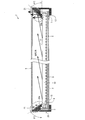
- FIG. 1 is a cross-sectional view showing the configuration of the light source unit of the present embodiment.
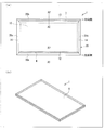
- 2A is a plan view showing the configuration of the light source unit, and
- FIG. 2B is a perspective view showing the configuration of the light source unit.
- a lighting device such as a ceiling light can be cited as an example of a lighting device including a light source unit.
- the light source unit and the lighting device are not limited to this.
- a lighting device is also provided with a plurality of light source units arranged side by side.
- the light source unit 1 of the present embodiment has a rectangular outer shape, and a plurality of LEDs (Light Emitting Diode: light emission) as a light source on one side of the long side.
- Diode) group 4 is provided, and an opposing surface reflecting member 7 is provided on the other side of the long side.
- the size of the light extraction area is, for example, 907 mm ⁇ 510 mm.
- the LED group 4 uses LEDs in which 72 LED packages having a width of 5.6 mm and a height of 3.0 mm are arranged in a row, and light is incident from one end surface of the long side of the light guide plate 10 described later.
- the thickness of the light guide plate 10 is, for example, 3.0 mm.
- the light source unit 1 includes a chassis 2, an LED substrate 3, an LED group 4, a reflection sheet 5, a light diffusing member 6 as a cover member, an opposing surface reflecting member 7, a light guide plate 10, and a housing.
- the frame 20 is provided.
- the frame 20 refers to an outer frame portion configured to surround the periphery of the light guide plate 10 in the casing.
- the housing is not necessarily configured integrally, and the portion covering the lower surface of the light guide plate 10 and the frame portion may be configured separately.
- the chassis 2, the reflection sheet 5, the light guide plate 10, and the light diffusion member 6 are arranged in order from the bottom.
- the light emitting surface side of the light guide plate 10 is described as the upper side.
- the lower side is the light guide plate 10. The light emitting surface side.
- the chassis 2 is provided on the side opposite to the exit surface 11 of the light guide plate 10, thereby covering the back side of the light source unit 1.
- the chassis 2 uses, for example, an aluminum sheet metal member having a thickness of 0.5 mm.
- an LED group 4 as a light source is mounted on the LED board 3.
- the light source is preferably the LED group 4 in order to save space.
- the light source is not necessarily limited to this and is a light source of another light emission method such as CCFL. It does not matter.
- the light guide plate 10 receives light emitted from the LED group 4 mounted on the LED substrate 3, and receives the received light between the emission surface 11 and the back surface of the light guide plate 10 and in a direction parallel to the light guide direction.
- the light is propagated inside the light guide plate 10 while being totally reflected between the both side surfaces, and is mainly emitted from the emission surface 11.
- the light guide plate 10 is made of a transparent material having high light transmittance, and is made of, for example, PMMA (acrylic), PC (polycarbonate), PS (polystyrene), or the like.
- the light guide plate 10 has a plate shape and the emission surface 11 has a quadrangular shape.
- a plurality of light extraction patterns 8 that are light diffusion portions are formed on the back surface of the light guide plate 10 at intervals.
- the light extraction pattern 8 can also be disposed on the light exit surface 11 side of the light guide plate 10.
- the light extraction pattern 8 is formed, for example, by printing in the form of dots on the back surface of the light guide plate 10.
- UV ink is used for printing.
- the present invention is not necessarily limited to this, and it may be a diffusing ink containing other diffusing particles, or ink jet printing or a light guide plate 10 provided with irregularities such as a prism shape.
- the optical path of light propagating through the light guide plate 10 can be changed.
- the light extraction pattern 8 diffuses the incident light when light propagating through the light guide plate 10 enters the light extraction pattern 8 formed on the back surface of the light guide plate 10. Change the direction of light travel. As a result, at least a part of the light diffused by the light extraction pattern 8 is emitted from the emission surface 11 to the outside without being totally reflected by the emission surface 11.
- the reflection sheet 5 re-enters the light guide plate 10 with the light reflected from the rear surface of the light guide plate 10 while the total reflection condition is broken while the light incident on the light guide plate 10 from the LED group 4 is guided, or The light is transmitted and light is extracted to the exit surface 11 side.
- the reflection sheet 5 uses, for example, a resin sheet having a trade name “E6D6 (manufactured by Toray Industries, Inc.)” having a thickness of 0.3 mm.
- the light diffusing member 6 is provided above the light exit surface 11 of the light guide plate 10 and protects the light guide plate 10 and diffuses the light emitted from the light guide plate 10 to suppress unevenness in light quantity, that is, uneven brightness. It has a function to do.
- the light diffusing member 6 is preferably a light shade made of glass fiber from the viewpoint of flexibility during installation.
- the present invention is not necessarily limited thereto, and may be a diffusion material, a diffusion plate having fine bubbles, or another type of light diffusion member such as Japanese paper or cloth.
- the light diffusion member 6 uses a resin sheet made of a trade name “light shade (manufactured by Nittobo Co., Ltd.)” using glass fiber as a material. It is arranged at a position of 10.5 mm above the light guide plate 10.
- the frame 20 covers the periphery of the light guide plate 10 in a frame shape, and the bottom side supports the chassis 2 and the front side supports the light guide plate 10.
- the frame 20 is preferably composed of an aluminum (Al) extruded member in consideration of heat dissipation when the LED group 4 is directly or indirectly arranged.
- Al aluminum
- it is not limited to the aluminum (Al) profile extrusion member, and may be a sheet metal member or a resin member of other metal.
- the light source unit 1 includes a rectangular light guide plate 10 that emits light incident from the light incident portion 12 that is one side end surface from the exit surface 11; Since the LED group 4 that enters light into the light incident portion 12 of the light guide plate 10 is provided, the edge light type light source unit 1 using the one-side incident type light guide plate 10 is provided.
- the edge light type light source unit 1 using such a one-side incident type light guide plate 10 has an orientation characteristic that light is emitted from the light guide plate 10 in a direction deviated from the light incident direction. Therefore, light is emitted strongly to the side opposite to the light incident side.
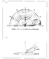
- the orientation characteristics of the light emitted from the light guide plate 10 in the edge light type light source unit 1 using the one-side incident type light guide plate 10 is about A luminance of intensity 1 is obtained at 75 degrees, but the intensity decreases to a luminance of 0.8 at about 60 degrees, and decreases to a luminance of 0.4 at about 45 degrees.
- the light emitted from the light guide plate 10 in the edge light type light source unit 1 using the one-side incident type light guide plate 10 has a large luminance on the side opposite to the light incident side of the light emitted from the light guide plate 10. Conversely, there is a problem that the luminance on the light incident side is reduced.
- the light incident portion 12 side of the light guide plate 10 and the opposite side surface 13 as the opposite side facing the light incident portion 12 are A frame 20 is provided as a casing, each of which includes an inclined portion for guiding light emitted from the light exit surface 11 of the light guide plate 10 toward the side of the light guide plate 10 to the side of the light guide plate 10. ing. That is, in the frame 20, an inclined portion for raising light upward is provided on the light incident portion 12 of the light guide plate 10 and the opposite side surface 13 thereof.
- the cross-sectional shape of the frame 20 becomes an inclined shape as it proceeds in the direction of the light diffusing member 6 on the exit surface 11 side, as shown in FIG. Yes.
- the inclined shape of the frame 20 is provided on all four sides of the light source unit 1.
- the LED side inclined portion 20a is provided on the side where the LED group 4 is provided, and the opposing surface side inclined portion 20b is provided on the side where the opposing surface reflecting member 7 is provided. Further, as shown in FIG. 2A, other surface side inclined portions 20c and 20c are provided on the other pair of surfaces, respectively.
- the LED side inclined portion 20a, the opposing surface side inclined portion 20b, and the other surface side inclined portions 20c and 20c of the frame 20 are provided with inclined portion reflecting members 21 made of a reflective sheet, respectively, thereby providing a light guide plate.
- the light emitted toward the side of the light guide plate 10 is guided to the upper side of the emission surface 11.
- the inclined portion reflecting member 21 has a highly reflective light scattering surface, and for example, a trade name “E6D6 (manufactured by Toray Industries, Inc.)” having a thickness of 0.3 mm is used. Note that the inclined portion reflecting member 21 is not limited to the above-described reflecting sheet, but is a type in which a highly reflecting paint is applied to the frame 20, a coloring process by anodizing, or a highly reflecting plastic represented by polycarbonate. It may be a member.
- the relationship between the light incident portion side inclined portion angle ⁇ 1 of the LED side inclined portion 20a and the opposed side inclined portion angle ⁇ 2 of the opposed surface side inclined portion 20b is set to satisfy ⁇ 1> ⁇ 2. .
- the opposed side inclined portion angle ⁇ 2 of the opposed surface side inclined portion 20b is made loose, and the light incident portion side inclined portion angle ⁇ 1 of the LED side inclined portion 20a is made steep.
- the luminance distribution can be made uniform as a whole. That is, the luminance C1 on the LED side inclined portion 20a side ⁇ the luminance C2 on the opposed surface side inclined portion 20b side can be set.
- the light source unit 1 that can achieve uniform luminance distribution in the side edge type light source unit 1 using the one-side incident type light guide plate 10.
- the configuration of the present embodiment is a side-edge type light source unit 1 using a one-side incident type light guide plate 10, it is lighter than a side-edge type light source unit using a both-side incident type light guide plate.
- an inexpensive light source unit 1 can be provided.
- both the light incident portion side inclined portion angle ⁇ 1 and the opposing side inclined portion angle ⁇ 2 are 90 ° or less. Therefore, the light emitted above the opposing side surface 13 of the light guide plate 10 can be guided above the light incident portion 12 by the reflection of the opposing surface side inclined portion 20b.
- the light incident portion side inclined portion angle ⁇ 1 and the opposing side inclined portion angle ⁇ 2 are: 60 ° ⁇ ⁇ 1 ⁇ 90 °, 45 ° ⁇ ⁇ 2 ⁇ 90 ° It is preferable to have the relationship
- the light source unit 1 that can surely eliminate the uneven brightness and make the brightness distribution uniform by evaluating the experimental angular range described later.
- the light guide plate 10 has a pair of vertical surfaces 14 and 14 that are perpendicular to one side end surface that is the light incident portion 12 and the emission surface 11 and that face each other (see FIG. 2 (see (a)), and the frame 20 includes other surface side inclined portions 20c and 20c as inclined portions on the pair of vertical surfaces 14 and 14 side of the light guide plate 10, respectively. It is preferable that the other surface side inclined portions 20c and 20c on the pair of vertical surfaces 14 and 14 have the same inclination angle.
- the light guide plate 10 is rectangular in the present embodiment, but is not necessarily limited thereto, and may be a polygon such as a hexagon.
- the inclination angles are made different from each other.
- the other surface side inclined portions 20c and 20c also on the vertical surfaces 14 and 14, the luminance unevenness on the other surface inclined portions 20c and 20c side of the other pair of vertical surfaces 14 and 14 can be eliminated.
- the other surface-side inclined portions 20c and 20c of the other pair of vertical surfaces 14 and 14 have the same luminance condition, and therefore it is not necessary to change the inclination angle. Therefore, it is preferable that the inclination angles of the other-surface inclined portions 20c and 20c on the pair of vertical surfaces 14 and 14 are the same.
- the shapes of the other surface side inclined portions 20 c and 20 c are symmetrical with respect to the vertical surfaces 14 and 14 with the light guide plate 10 interposed therebetween.
- the light source unit 1 of the present embodiment preferably includes the light diffusion member 6 that covers the entire upper surfaces of the light guide plate 10 and the frame 20, and the entire upper surfaces of the light guide plate 10 and the frame 20 are preferably light emitting surfaces. .
- the light diffusing member 6 can diffuse light that has reached the light diffusing member 6 at various angles to obtain a substantially uniform diffusing surface (Lambertian) light distribution.
- the first effect is an effect of making the luminance uniform between the light guide plate 10 and the inclined surface portion of the frame 20, and thereby, between the light guide plate 10 portion and the inclined surface portion of the frame 20.
- the luminance difference is small and the boundary can be made inconspicuous. Therefore, since the light emitting surface can be extended not only to the light guide plate 10 but also to the inclined surface portion of the frame 20, the problem of being a dark portion in the frame 20 can be solved.
- the inclined surface preferably extends to the vicinity of the edge that is the outermost part of the frame 20.
- the second effect is an effect of extending the light emitting region to the outside of the inclined surface.
- the inclined surface extends as much as possible to the vicinity of the edge that is the outermost part of the frame 20, but the inclined surface cannot be completely extended to the edge due to design constraints. A portion that is not an inclined surface may remain at the edge.
- the light diffusing member 6 covers the entire upper surface of the frame 20 including the edge, so that the light from the inclined surface is diffused inside the light diffusing member 6 and then is more than the edge. By emitting the part, the light emitting region can be extended to the outside of the inclined surface.
- the entire surface including the frame 20 can be used as the light emitting surface by covering the inclined portion of the frame 20 and the entire upper surface of the light guide plate 10 with the light diffusion member 6.
- the frame 20 does not become a dark portion, and in particular, in the form in which the plurality of light source units 1 are arranged in a plane, it is possible to suppress the conspicuous portion of the joint from being noticeable.
- the lighting device of the present embodiment includes the light source unit 1 of the present embodiment.
- the light source unit 1 of this Embodiment is applicable to the illuminating device which illuminates the inside of a room.
- a plurality of light source units 1 of the present embodiment are arranged.
- the luminance distribution in the side edge type light source unit 1 using the one-side incident type light guide plate 10 is made uniform, and luminance unevenness between the light source units 1 when a plurality of such light source units 1 are arranged is prevented.
- a lighting device can be provided.
- a two-dimensional color luminance meter having a trade name “CA-2000 (manufactured by Konica Minolta Co., Ltd.)” was used.
- FIG. 5A is a plan view showing luminance unevenness of the light diffusing member of the light source unit showing the A1-A1 ′ direction and the A2-A2 ′ direction of FIG. 2A
- FIG. 5A is a plan view showing luminance unevenness of the light guide plate of the light source unit in the portion shown in FIG. 5A
- FIG. 5C is a cross-sectional view of the light source unit showing the configuration of the portion shown in FIG.
- the left side represents luminance unevenness near the light incident portion 12
- the right side represents luminance unevenness near the opposing side surface 13.
- 5A shows the luminance unevenness when the light diffusing member 6 is arranged
- FIG. 5B shows the luminance unevenness when the light diffusing member 6 is removed.
- the luminance distribution when the light diffusing member 6 is removed shows that the luminance is different between the vicinity of the light incident portion 12 and the vicinity of the opposite side surface 13 as shown in FIG.
- ⁇ 1 and ⁇ 2 are respectively set to 90 ° and 60 °.
- the luminance distribution was determined when the angle was 45 °, 30 °.
- a two-dimensional color luminance meter having the above-mentioned trade name “CA-2000 (manufactured by Konica Minolta Co., Ltd.)” was used.
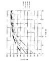
- FIG. 6 is a distribution diagram showing the luminance distribution in the A1-A1 ′ direction of FIG. 2A, that is, the luminance distribution in the vicinity of the light incident portion 12.
- FIG. 7 is a distribution diagram showing the luminance distribution in the A2-A2 ′ direction of FIG.
- ⁇ 1 and ⁇ 2 are 90 ° or less, and ⁇ 1> ⁇ 2 should be satisfied.
- the light incident part side inclined part angle ⁇ 1 and the opposing side inclined part angle ⁇ 2 are: 60 ° ⁇ ⁇ 1 ⁇ 90 °, 45 ° ⁇ ⁇ 2 ⁇ 90 ° Is determined to be optimal.
- the frame 20 With the LED-side inclined portion 20a and the opposing surface-side inclined portion 20b having the light incident portion-side inclined portion angle ⁇ 1 and the opposed-side inclined portion angle ⁇ 2, the luminance distribution can be made uniform. Is possible.
- the light source units 1 of the present embodiment are arranged in parallel at the respective angles, the luminance in the vicinity of the light incident portion 12 and the luminance in the vicinity of the opposite side surface 13 of the other light source unit 1 at the joint. Can be substantially matched. Therefore, it is possible to eliminate the luminance difference between the seams when the light source units 1 of the present embodiment are connected.
- the light source unit 1 includes a light guide plate 10 that emits light incident from a light incident portion 12 that is one side end surface from an output surface 11, and the light guide plate. 10, a light source unit 1 including a light source (LED group 4) that makes light incident on a light incident portion 12. 13), an inclined portion (LED-side inclined portion 20a) for guiding light emitted toward the side of the light guide plate 10 out of the light emitted from the output surface 11 of the light guide plate 10 to the upper side of the output surface 11.
- a light guide plate 10 that emits light incident from a light incident portion 12 that is one side end surface from an output surface 11, and the light guide plate.
- a light source unit 1 including a light source (LED group 4) that makes light incident on a light incident portion 12. 13), an inclined portion (LED-side inclined portion 20a) for guiding light emitted toward the side of the light guide plate 10 out of the light emitted from the output surface 11 of the light guide plate 10 to the upper side of the output surface 11.
- a housing (frame 20) provided with the opposing surface side inclined portion 20b) is provided, and an inclined portion (LED-side inclined portion 20a) on the light incident portion 12 side of the housing (frame 20).
- Light source (LED group) on the exit surface 11 of the light guide plate 10 ) Side is defined as the light incident portion-side inclined portion angle ⁇ 1
- the guiding portion at the inclined portion (opposing surface-side inclined portion 20b) on the opposite side (opposing side surface 13) of the casing (frame 20) is used.
- the angle formed with the surface extending from the opposite side (opposite side surface 13) end of the light exit surface 11 of the optical plate 10 is the opposite side inclined portion angle ⁇ 2, ⁇ 1> ⁇ 2 It is characterized by having a relationship.
- the light source unit is an edge light type light source unit using a one-side incident type light guide plate.
- the edge light type light source unit using such a one-side incident type light guide plate the light emitted from the light guide plate has a high luminance on the side opposite to the light incident side, and conversely, the luminance on the light incident side becomes small. There's a problem.
- the light emitted from the light exit surface of the light guide plate toward the side of the light guide plate on the light incident portion side of the light guide plate and the opposite side facing the light incident portion are provided.
- the relationship between the light incident portion side inclined portion angle ⁇ 1 and the opposing side inclined portion angle ⁇ 2 in the inclined portion is set to ⁇ 1> ⁇ 2.
- the luminance is increased on the light incident portion side and the luminance is decreased on the opposite side, so that the luminance distribution can be made uniform as a whole.
- both the light incident part side inclined part angle ⁇ 1 and the opposing side inclined part angle ⁇ 2 are 90 ° or less.
- the light emitted to the opposite side of the light guide plate can be guided to the light incident part side by the reflection of the inclined part.
- the light incident portion side inclined portion angle ⁇ 1 and the opposing side inclined portion angle ⁇ 2 are: 60 ° ⁇ ⁇ 1 ⁇ 90 °, 45 ° ⁇ ⁇ 2 ⁇ 90 ° It is preferable to have the relationship
- the light guide plate 10 includes a pair of vertical surfaces 14 and 14 that are perpendicular to one side end surface that is the light incident portion 12 and the emission surface 11 and that face each other.
- the frame (frame 20) includes inclined portions (other side inclined portions 20c and 20c) on the pair of vertical surfaces 14 and 14 side of the light guide plate 10, respectively. It is preferable that the inclination angles of the inclined portions on the surfaces 14 and 14 side (other side inclined portions 20c and 20c) are the same.
- the light source unit 1 includes the light diffusion member 6 that covers the entire upper surface of the light guide plate 10 and the housing (frame 20), and the entire upper surface of the light guide plate 10 and the housing (frame 20). A light emitting surface is preferred.
- the entire surface including the frame 20 can be used as the light emitting surface.
- the frame portion does not become a dark portion, and in particular, in the form in which a plurality of light source units are arranged in a plane, it can be suppressed that the joint portion is conspicuous.
- the lighting device includes the light source unit 1 described above in order to solve the above-described problem.
- the light source unit of the present invention can be applied to a lighting device that illuminates the interior of a room.
- a plurality of the light source units 1 described above are arranged.
- the luminance distribution in the vicinity of the outer frame portion in the side edge type light source unit using the one-side incident type light guide plate is made uniform, and a plurality of light source units of this type are arranged between the light source units.
- An illumination device that can prevent uneven brightness can be provided.
- the present invention relates to a side-edge type light source unit and an illuminating device using a one-side incident type light guide plate, and to uniformize the luminance distribution in the vicinity of the outer frame portion of the light emitted from the one-side incident type light guide plate.
- the present invention can be applied to a light source unit and a lighting device.
Landscapes
- Physics & Mathematics (AREA)
- Nonlinear Science (AREA)
- Mathematical Physics (AREA)
- Chemical & Material Sciences (AREA)
- Crystallography & Structural Chemistry (AREA)
- General Physics & Mathematics (AREA)
- Optics & Photonics (AREA)
- Planar Illumination Modules (AREA)
Abstract
本発明の光源ユニット(1)は、導光板(10)の光入射部(12)側と該光入射部(12)に対向する対向側面(13)とに、該導光板(10)の出射面(11)から出射された光のうち導光板(10)の側方に向けて出射された光を出射面(11)上方に導くためのLED側傾斜部(20a)及び対向面側傾斜部(20b)をそれぞれ備えたフレーム(20)が設けられている。フレーム(20)のLED側傾斜部(20a)の光入射部側傾斜部角度θ1と、フレーム(20)の対向面側傾斜部20bの対向側傾斜部角度θ2との関係は、θ1>θ2となっている。
Description
本発明は、片側入射方式の導光板を用いたサイドエッジ型の光源ユニット及び照明装置に関するものである。
従来、液晶TVに使用される液晶表示装置等の照明機器において、薄型化を実現するために、光源から側面に入射された光を面状に出射させるサイドエッジ(サイドライト又はエッジライトともいう)型の導光板を備えた光学系が多用されている。
このようなサイドエッジ型の導光板では、該導光板の端面(以降、「入射端面」とも呼ぶ)に対向するようにLED(Light Emitting Diode:発光ダイオード)等の光源を配置し、導光板の各入射端面から光を入射させる。入射された光は、該導光板の内部を反射しながら伝搬し、該導光板の光出射面から出射される。
ところで、片側入射方式の導光板を用いたエッジライト型の光源ユニットでは、光入射方向に対して偏った方向に導光板から光が出射されるため、光入射側の反対側に強く光が出射されるという配向特性を有している。このため、複数の光源ユニットを並べて、各光源ユニット間をシームレスに光らせる照明に用いるには、光源ユニットの発光面全体を光らせる必要があるが、前述の配光特性のため導光板からの出射光は光入射側とは反対側の輝度が大きく、逆に光入射側の輝度が小さくなるという問題がある。
ここで、導光板を用いたエッジライト型の光源ユニットは、従来、液晶表示装置に広く用いられている技術ではあるが、液晶表示装置ではこのような問題は発生しない。その理由は、液晶表示装置は液晶パネルの部分に光が出射されればよく、液晶パネルの枠部分であるフレーム部分が光る必要はないためである。言い換えれば、液晶表示装置の用途では液晶パネルの下部が位置する照明装置中央部分の輝度のみを考慮すればよく、照明装置の外枠部分の輝度分布を考慮する必要はないのである。
この種の片側入射方式の導光板を用いたサイドエッジ型の光源ユニットにおける光源ユニット全体の輝度分布の向上を図るものとして、例えば特許文献1に開示された面光源装置が知られている。
上記特許文献1に開示された面状光源100は、図8に示すように、点状又は線状の光源101と、その光源101の光を側面102aから入射し、平面状の一面102cからほぼ均一に照射する導光板102とからなる面状光源ユニット110が複数個並設して設けられている。そして、隣接する該面状光源ユニット110の間に存在する光源101の上面側に、その光源101を覆うように、山形状の乱反射部材103が設けられている。さらに、その複数個の面状光源ユニット110の一面102c側に一定間隔Hを介して光拡散板105が設けられている。
上記面状光源100では、導光板102の側面から光を導入する面状光源ユニット110を何個も並列することにより大形の面状光源としながら、配列するだけで、簡単にいくらでも大形化することができ、しかも電飾看板のような大形の表示パネルでも、均一に照射することができる安価な面状光源を提供するものとなっている。ここで、導光板102と光拡散板105との距離を10~20mm程度大きくする必要があるが、光拡散板105の位置で継ぎ目の影は全く生じないで均一な面状光源とすることができる。
ところで、上記従来の特許文献1に開示された面状光源100では、面状光源ユニット110間につなぎ目が存在しているが、そのつなぎ目に山形状の乱反射部材103が設けられている。
しかしながら、特許文献1に開示された面状光源100は、導光板210として単一ではなく複数の導光板を用いる際に導光板同士の継ぎ目の輝度分布を改善するものであり、照明装置全体として捉えると、その目的は、照明装置の中央部分に複数の導光板を用いる構成において、照明装置中央部分の輝度分布を改善するものであるといえる。したがって、複数の導光板全体を格納する筺体の外枠部分の輝度分布を改善することができない。この結果、照明装置を室内用の照明に用いる場合は、照明装置の外側に向けた室内照度が低下する他、該照明装置を筺体の外枠同士が隣接するように複数隣接して配列した複合照明装置として応用した場合に、筺体の外枠部分の輝度低下が軽減されず、照明装置同士の継ぎ目が視認され易くなるという問題がある。
また、山形状の乱反射部材103は、二等辺三角形からなる山形状である。このため、片側入射方式の導光板を用いたサイドエッジ型の光源ユニットにおいては、光入射側の反対側に強く光が出射されるという配向特性を有するという観点からすると、乱反射部材103として二等辺三角形の山形のように、傾斜角を等しくした場合には、各面状光源ユニット110間につなぎ目の輝度を他の部分と十分に均一にすることは困難であるという問題点を有している。
本発明は、上記従来の問題点に鑑みなされたものであって、その目的は、片側入射方式の導光板を用いたサイドエッジ型の光源ユニットにおける外枠部分近傍の輝度分布の均一化を図り、延いてはこの種の光源ユニットを複数並べる場合の光源ユニット間の輝度ムラを防止し得る光源ユニット及び照明装置を提供することにある。
本発明の一態様に係る光源ユニットは、上記の課題を解決するために、1つの側端面である光入射部から入射した光を出射面から出射する導光板と、該導光板の光入射部に光を入射する光源とを備えた光源ユニットにおいて、上記導光板の光入射部側と該光入射部に対向する対向側とに、該導光板の出射面から出射された光のうち導光板の側方に向けて出射された光を出射面上方に導くための傾斜部をそれぞれ備えた筐体が設けられていると共に、上記筐体の光入射部側の傾斜部における、導光板の出射面の光源側への延長面とのなす角度を光入射部側傾斜部角度θ1とし、上記筐体の対向側の傾斜部における、導光板の出射面の対向側端部外方への延長面とのなす角度を対向側傾斜部角度θ2とすると、
θ1>θ2
となる関係を有していることを特徴としている。
θ1>θ2
となる関係を有していることを特徴としている。
本発明の一態様に係る照明装置では、上記課題を解決するために、前記記載の光源ユニットを備えていることを特徴としている。
本発明の一態様に係る照明装置では、上記課題を解決するために、前記記載の光源ユニットが複数配列されていることを特徴としている。
本発明の一態様によれば、片側入射方式の導光板を用いたサイドエッジ型の光源ユニットにおける外枠部分近傍の輝度分布の均一化を図り、延いてはこの種の光源ユニットを複数並べる場合の光源ユニット間の輝度ムラを防止し得る光源ユニット及び照明装置を提供するという効果を奏する。
本発明の一実施形態について図1~図7に基づいて説明すれば、以下のとおりである。
本実施の形態の光源ユニットの構成について、図1及び図2の(a)(b)に基づいて説明する。図1は本実施の形態の光源ユニットの構成を示す断面図である。図2の(a)は上記光源ユニットの構成を示す平面図であり、図2の(b)は上記光源ユニットの構成を示す斜視図である。
尚、本実施の形態においては、光源ユニットを備えた照明装置の一例としてシーリングライト等の照明装置を挙げることができる。ただし、光源ユニット及び照明装置は、これに限定されるものではない。また、光源ユニットを複数個並べて配設したものも照明装置とする。
本実施の形態の光源ユニット1は、図2の(a)(b)に示すように、外形が長方形からなっており、長辺側の一辺に光源としての複数のLED(Light Emitting Diode:発光ダイオード)群4が設けられており、長辺側の他の一辺に対向面反射部材7が設けられている。
本実施の形態の光源ユニット1では、光取出し領域の寸法が例えば907mm×510mmである。LED群4には、幅5.6mm、高さ3.0mmのLEDパッケージを一列に72個並べたLEDを使用し、後述する導光板10の長辺の端面一辺から入光させている。導光板10の厚みは例えば3.0mmである。
すなわち、光源ユニット1は、図1に示すように、シャーシ2、LED基板3、LED群4、反射シート5、カバー部材としての光拡散部材6、対向面反射部材7、導光板10及び筐体としてのフレーム20を備えている。尚、ここでフレーム20とは、筺体のうち導光板10の周囲を囲むように構成された外枠部分のことを指す。筺体は必ずしも一体で構成される必要はなく、導光板10の下面を覆う部分とフレーム部分とが別体で構成されていてもよい。
上記光源ユニット1では、下から順に説明すると、シャーシ2、反射シート5、導光板10及び光拡散部材6が配置されている。ここで、本実施の形態の光源ユニット1では、導光板10の発光面側を上側として説明するが、光源ユニット1がシーリングライト等の照明機器に使用される場合には、下側が導光板10の発光面側となる。
上記シャーシ2は、導光板10の出射面11とは反対側に設けられており、これによって、光源ユニット1の裏面側を覆っている。本実施の形態では、シャーシ2は、例えば0.5mm厚のアルミ板金部材を使用している。
上記LED基板3には、光源としてのLED群4が搭載されている。ここで、本実施の形態では、光源は、省スペース化するためにもLED群4であることが好ましいが、本発明においては、必ずしもこれに限らず、CCFL等の他の発光方式の光源であっても構わない。
上記導光板10は、LED基板3に搭載されたLED群4から出射される光を受光し、受光した光を出射面11と導光板10の裏面との間、及び導光方向と平行方向の両側面の間において全反射させつつ導光板10の内部で伝播させると共に、主に出射面11から出射させるものである。このため、導光板10は、光透過性の高い透明材料からなり、例えば、PMMA(アクリル)、PC(ポリカーボネート)、及びPS(ポリスチレン)等からなっている。
また、導光板10は、本実施の形態では、板状で出射面11が四角形状となっている。
上記導光板10の裏面には、図1に示すように、光拡散部である複数の光取出しパターン8が互いに間隔を置いて形成されている。尚、光取出しパターン8は、導光板10の出射面11側に配置することも可能である。
光取出しパターン8は、例えば、導光板10の裏面にドット状に印刷することにより形成されている。印刷には例えばUVインクを使用している。ただし、必ずしもこれに限らず、他の拡散粒子を配合した拡散インクであってもよく、又はインクジェット印刷や導光板10にプリズム形状などの凹凸を付与したものであっても構わない。
上述のように、導光板10の裏面に光取出しパターン8を形成することにより、導光板10内を伝播する光の光路を変更することができる。具体的には、光取出しパターン8は、導光板10内を伝播する光が導光板10の裏面に形成されている光取出しパターン8に入射すると、入射した光を拡散し、導光板10内における光の進行方向を変える。この結果、光取出しパターン8で拡散された光の少なくとも一部は、出射面11で全反射せずに該出射面11から外部に出射されることになる。
上記反射シート5は、LED群4から導光板10に入射した光が導光される間に全反射条件が破れて導光板10の裏面に出射された光を再度導光板10に入射し、又は透過させて出射面11側に光を取り出させるものである。本実施の形態では、反射シート5は、例えば0.3mm厚の商品名「E6D6(東レ株式会社製)」の樹脂シートを使用している。
上記光拡散部材6は、導光板10の出射面11の上方に設けられており、導光板10を保護すると共に、導光板10から出射された光を拡散して光量のムラつまり輝度ムラを抑制する機能を有している。この光拡散部材6は、設置時のフレキシブル性の観点から、グラスファイバーによるライトシェードであることが好ましい。ただし、必ずしもこれに限らず、拡散材や微細気泡を有する拡散板、又は和紙や布等の他の方式の光拡散部材であっても構わない。本実施の形態では、光拡散部材6には、素材にグラスファイバーを用いた商品名「ライトシェード(日東紡株式会社製)」からなる樹脂シートを使用しており、この光拡散部材6は、導光板10の上方10.5mmの位置に配されている。
上記フレーム20は、導光板10の周囲を枠状に覆っており、底面側はシャーシ2を支持すると共に、表面側は導光板10を支持している。このフレーム20は、LED群4を直接的又は間接的に配したときの放熱性を考慮し、アルミニウム(Al)の異形押出し部材で構成することが好ましい。ただし、アルミニウム(Al)の異形押出し部材に限定されるものではなく、他の金属の板金部材や樹脂部材であっても構わない。
このように、本実施の形態の光源ユニット1は、図1に示すように、1つの側端面である光入射部12から入射した光を出射面11から出射する方形の導光板10と、該導光板10の光入射部12に光を入射するLED群4とを備えていることから、片側入射方式の導光板10を用いたエッジライト型の光源ユニット1となっている。
このような片側入射方式の導光板10を用いたエッジライト型の光源ユニット1では、光入射方向に対して偏った方向に導光板10から光が出射されるという配向特性を有していることから、光入射側の反対側に強く光が出射される。
具体的には、片側入射方式の導光板10を用いたエッジライト型の光源ユニット1における導光板10からの出射光の配向特性は、図3の(a)(b)に示すように、約75度において強度1の輝度が得られるが、約60度においては強度が0.8の輝度に低下し、約45度においては強度0.4の輝度に低下する。
この結果、片側入射方式の導光板10を用いたエッジライト型の光源ユニット1における導光板10からの出射光は、導光板10からの出射光は光入射側とは反対側の輝度が大きく、逆に光入射側の輝度が小さくなるという問題がある。
そこで、本実施の形態の光源ユニット1では、図1に示すように、まず、導光板10の光入射部12側と該光入射部12に対向する対向側としての対向側面13とに、該導光板10の出射面11から出射された光のうち導光板10の側方に向けて出射された光を出射面の上方に導くための傾斜部をそれぞれ備えた筐体としてのフレーム20を設けている。すなわち、フレーム20において、導光板10の光入射部12とその対向側面13に光を上方に立ち上げるための傾斜部を設けている。
具体的には、本実施の形態の光源ユニット1では、フレーム20の断面形状は、図1に示すように、出射面11側の光拡散部材6の方向に進むに伴って傾斜形状になっている。上記フレーム20の傾斜形状は、光源ユニット1の4つの辺の全てに設けられている。
詳細には、LED群4が配設された辺ではLED側傾斜部20aが設けられ、対向面反射部材7が配設された辺では対向面側傾斜部20bが設けられている。さらに、他の一対の面には、図2の(a)に示すように、他面側傾斜部20c・20cがそれぞれ設けられている。
そして、フレーム20のLED側傾斜部20a、対向面側傾斜部20b及び他面側傾斜部20c・20cには、反射シートからなる傾斜部反射部材21がそれぞれ設けられており、これによって、導光板10の出射面11から出射された光のうち導光板10の側方に向けて出射された光を出射面11の上方に導くようになっている。
上記傾斜部反射部材21は、高反射の光散乱面を有しており、例えば、0.3mm厚の商品名「E6D6(東レ株式会社製)」が使用されている。尚、傾斜部反射部材21は、上述したような反射シートに限定されるものではなく、フレーム20に高反射塗料を塗装した形式や、アルマイト処理による着色処理、又はポリカーボネートに代表される高反射プラスチック部材であっても構わない。
この場合、図4に示すように、光入射方向に偏った方向に導光板10から光が出射されるため、光入射部12の反対側に強く光が出射される。この結果、対向側の対向面側傾斜部20bに強い光が当たることから、対向面側傾斜部20bの輝度が大きく、逆に光入射部12側のLED側傾斜部20aの輝度が小さくなる。
ここで、本実施の形態では、LED側傾斜部20aの光入射部側傾斜部角度θ1と対向面側傾斜部20bの対向側傾斜部角度θ2との関係をθ1>θ2となるようにしている。
すなわち、対向面側傾斜部20bの対向側傾斜部角度θ2を緩くし、LED側傾斜部20aの光入射部側傾斜部角度θ1を急になるようにしている。
このような傾斜角度にすることによって、輝度分布を改善することが可能となる。具体的には、傾斜角度が急峻である場合、光源ユニット1の光出射方向から見たときの傾斜部の投影面積は狭くなり、狭い投影面積に光が集中することになり、輝度が高くなる。逆に、傾斜角度が緩やかである場合、光源ユニット1の光出射方向から見たときの傾斜部の投影面積が広くなるため、輝度が小さくなる。
この結果、本実施の形態では、光入射部12では輝度が高くなり、対向側面13では輝度が低くなることから、全体として輝度分布の均一化を図ることができる。すなわち、LED側傾斜部20a側の輝度C1≒対向面側傾斜部20b側の輝度C2とすることが可能となる。
したがって、片側入射方式の導光板10を用いたサイドエッジ型の光源ユニット1における輝度分布の均一化を図り得る光源ユニット1を提供することができる。
また、本実施の形態の構成は片側入射方式の導光板10を用いたサイドエッジ型の光源ユニット1であることから、両側入射方式の導光板を用いたサイドエッジ型の光源ユニットと比べて光源やそれに付随する基板等が半分で済むため、安価な光源ユニット1を提供することが可能となる。
また、本実施の形態の光源ユニット1では、光入射部側傾斜部角度θ1及び対向側傾斜部角度θ2のいずれもが90°以下であることが好ましい。これにより、導光板10の対向側面13の上方に出射された光を対向面側傾斜部20bの反射により光入射部12の上方に導くことができる。
また、本実施の形態の光源ユニット1では、光入射部側傾斜部角度θ1及び対向側傾斜部角度θ2は、
60°≦θ1≦90°、45°≦θ2<90°
となる関係を有していることが好ましい。
60°≦θ1≦90°、45°≦θ2<90°
となる関係を有していることが好ましい。
これにより、後述する実験的な角度範囲の評価により、確実に輝度むらを解消し、輝度分布の均一化を図り得る光源ユニット1を提供することができる。
また、本実施の形態の光源ユニット1では、導光板10は、光入射部12である1つの側端面と出射面11とに垂直であってかつ互いに対向する一対の垂直面14・14(図2の(a)参照)を有していると共に、フレーム20は、導光板10の一対の垂直面14・14側に傾斜部としての他面側傾斜部20c・20cをそれぞれ備えており、該一対の垂直面14・14側の他面側傾斜部20c・20cの傾斜角度は同一であることが好ましい。尚、導光板10は、本実施の形態では方形としているが、必ずしもこれに限らず、例えば六角形等の多角形であってもよい。
これにより、フレーム20における光入射部12のLED側傾斜部20aとフレーム20における対向側面13側の対向面側傾斜部20bとの関係においては、互いに傾斜角度を異なるようにするが、他の一対の垂直面14・14にも他面側傾斜部20c・20cを備えることによって、他の一対の垂直面14・14の他面側傾斜部20c・20c側の輝度むらを解消することができる。そして、この場合、他の一対の垂直面14・14の他面側傾斜部20c・20cについては、輝度の条件は同一であることから、傾斜角度を変える必要はない。したがって、該一対の垂直面14・14側の他面側傾斜部20c・20cの傾斜角度は同一とするのが好ましい。これにより、垂直面14・14にも他面側傾斜部20c・20cの形状は、導光板10を挟んで対称となっている。
この結果、さらに、導光板10全体の輝度分布の均一化を図り得る光源ユニット1を提供することができる。
本実施の形態の光源ユニット1では、導光板10及びフレーム20の上面全体を覆う光拡散部材6を有しており、導光板10及びフレーム20の上面全体が発光面となっていることが好ましい。
すなわち、光拡散部材6は、様々な角度で該光拡散部材6に到達した光を拡散させて、おおよそ均等拡散面(ランバーシアン)配光にすることができる。このため、本実施の形態において、大きくは2つの効果を有している。第1の効果は、導光板10の部分とフレーム20の傾斜面の部分とで輝度を均一化する効果であり、これにより、導光板10の部分とフレーム20の傾斜面の部分との間で輝度差が少なく、境界が目立たなくすることができる。したがって、導光板10の部分のみならず、フレーム20の傾斜面の部分まで発光面を拡張することができるため、フレーム20で暗部となる問題を解消することができる。尚、傾斜面はフレーム20の最外部である縁部近傍まで伸びていることが望ましい。
第2の効果は、傾斜面の外部へ発光領域を延伸する効果である。上述のように、傾斜面はフレーム20の最外部である縁部近傍まで可能な限り伸びていることが望ましいが、設計上の制約により完全には傾斜面を縁部まで伸ばすことができず、縁部に傾斜面でない部分が残る場合がある。このような場合であっても、光拡散部材6が縁部も含めてフレーム20の上面全体を覆うことにより、傾斜面からの光が光拡散部材6の内部で拡散したうえで縁部より一部が出射されることにより、傾斜面の外部へ発光領域を延伸することができる。
上記の効果により、フレーム20の傾斜部及び導光板10の上面全体を光拡散部材6にて覆うことによって、フレーム20を含む全面を発光面とすることができる。
したがって、フレーム20で暗部になることがなく、特に、複数の光源ユニット1を平面的に配列する形態において、継ぎ目部分が目立つのを抑制することができる。
また、本実施の形態の照明装置では、本実施の形態の光源ユニット1を備えている。これにより、本実施の形態の光源ユニット1を部屋の内部を照明する照明装置へ応用することができる。
また、本実施の形態の照明装置では、本実施の形態の光源ユニット1が複数配列されている。これにより、片側入射方式の導光板10を用いたサイドエッジ型の光源ユニット1における輝度分布の均一化を図り、この種の光源ユニット1を複数並べる場合の光源ユニット1間の輝度ムラを防止し得る照明装置を提供することができる。
上述した、片側入射方式の導光板10を用いたエッジライト型の光源ユニット1におけるフレーム20のLED側傾斜部20aの光入射部側傾斜部角度θ1及び対向面側傾斜部20bの対向側傾斜部角度θ2の適正値を求めるべく、実験を行った。
実験においては、最初に、光入射部側傾斜部角度θ1=対向側傾斜部角度θ2=30°として、そのときの輝度ムラの発生状況を確認した。測定には、商品名「CA-2000(コニカミノルタ株式会社製)」の二次元色彩輝度計を使用した。
その結果を、図5の(a)(b)(c)に示す。図5の(a)は、図2の(a)のA1-A1’方向及びA2-A2’方向を示す光源ユニットの光拡散部材の輝度ムラを示す平面図であり、図5の(b)は(a)に示す部分の光源ユニットの導光板の輝度ムラを示す平面図であり、図5の(c)は(a)に示す部分の構成を示す光源ユニットの断面図である。尚、図5の(a)(b)において、左側は光入射部12付近の輝度ムラを表し、右側は対向側面13付近の輝度ムラを表している。また、図5の(a)は、光拡散部材6を配置したときの輝度ムラを表しており、図5の(b)は光拡散部材6を取り外したときの輝度ムラを表している。
図5の(a)に示すように、光入射部側傾斜部角度θ1=対向側傾斜部角度θ2となっているように、互いの傾斜角度が同じであるにも関わらず、光入射部12付近の輝度の低下が対向側面13付近の輝度の低下よりも大きくなっていることが分かる。
また、光拡散部材6を取り除いたときの輝度分布は、図5の(b)に示すように、光入射部12付近と対向側面13付近との両者で輝度が異なっていることが分かる。それぞれ約45mm離れた導光板10上の輝度と比較すると、光入射部12付近では331/932*100=36%に対し、対向側面13付近では601/864*100=70%となっている。
この理由は、導光板10から出射した光の配光特性によるものであり、対向面側傾斜部20bにはLED側傾斜部20aにより多くの光が到達し、上面に立ち上げられるからである。これにより、傾斜部が同じ角度であっても、光拡散部材6を配置した場合でも光入射部12付近と対向側面13付近とで輝度差が生じることが分かる。
次に、フレーム20のLED側傾斜部20aの光入射部側傾斜部角度θ1及び対向面側傾斜部20bの対向側傾斜部角度θ2の適正値を求めるべく、θ1、θ2をそれぞれ90°、60°、45°、30°としたときの輝度分布を求めた。測定においては、前述の商品名「CA-2000(コニカミノルタ株式会社製)」の二次元色彩輝度計を使用した。
その結果を、図6及び図7に基づいて説明する。図6は、図2の(a)のA1-A1’方向の輝度分布つまり光入射部12付近の輝度分布を示す分布図である。また、図7は、図2の(a)のA2-A2’方向の輝度分布つまり対向側面13付近の輝度分布を示す分布図である。
図6及び図7に示すように、θ1=θ2の場合で比較すると、θ1=θ2=90°からの輝度低下率は、θ1の方が常に大きくなっている。そして、θ1、θ2共に、大きければ大きいほど輝度低下が小さいことが分かる。
このとき、θ1=60°及びθ2=45°の各傾斜部付近の輝度が略同じになっている。
このことから、一般に、θ1、θ2は90°以下であり、θ1>θ2とするのがよいことが分かる。
ただし、図6及び図7においては、θ1=45°、θ2=30°の条件では、傾斜部上部の輝度が急激に低下しているために、その暗部が単独で視認された。
したがって、光入射部側傾斜部角度θ1及び対向側傾斜部角度θ2は、
60°≦θ1≦90°、45°≦θ2<90°
とするのが、最適であると判断される。
60°≦θ1≦90°、45°≦θ2<90°
とするのが、最適であると判断される。
このような光入射部側傾斜部角度θ1及び対向側傾斜部角度θ2を備えたLED側傾斜部20a及び対向面側傾斜部20bをフレーム20に設けることにより、輝度の分布の均一化を図ることが可能となる。
また、それぞれ上記角度の構成で本実施の形態の光源ユニット1を並列に配置すれば、その繋ぎ目において、光入射部12近傍の輝度と、他の光源ユニット1の対向側面13近傍の輝度とを略一致させることが可能となる。したがって、本実施の形態の光源ユニット1繋ぎ合わせたときの継ぎ目の輝度差をなくすことができる。
尚、本発明は、上述した実施形態に限定されるものではなく、請求項に示した範囲で種々の変更が可能であり、本実施形態にそれぞれ開示された技術的手段を適宜組み合わせて得られる実施形態についても本発明の技術的範囲に含まれる。
(まとめ)
本発明の一態様に係る光源ユニット1は、上記の課題を解決するために、1つの側端面である光入射部12から入射した光を出射面11から出射する導光板10と、該導光板10の光入射部12に光を入射する光源(LED群4)とを備えた光源ユニット1において、上記導光板10の光入射部12側と該光入射部12に対向する対向側(対向側面13)とに、該導光板10の出射面11から出射された光のうち導光板10の側方に向けて出射された光を出射面11上方に導くための傾斜部(LED側傾斜部20a、対向面側傾斜部20b)をそれぞれ備えた筐体(フレーム20)が設けられていると共に、上記筐体(フレーム20)の光入射部12側の傾斜部(LED側傾斜部20a)における、導光板10の出射面11の光源(LED群4)側への延長面とのなす角度を光入射部側傾斜部角度θ1とし、上記筐体(フレーム20)の対向側(対向側面13)の傾斜部(対向面側傾斜部20b)における、導光板10の出射面11の対向側(対向側面13)端部外方への延長面とのなす角度を対向側傾斜部角度θ2とすると、
θ1>θ2
となる関係を有していることを特徴としている。
本発明の一態様に係る光源ユニット1は、上記の課題を解決するために、1つの側端面である光入射部12から入射した光を出射面11から出射する導光板10と、該導光板10の光入射部12に光を入射する光源(LED群4)とを備えた光源ユニット1において、上記導光板10の光入射部12側と該光入射部12に対向する対向側(対向側面13)とに、該導光板10の出射面11から出射された光のうち導光板10の側方に向けて出射された光を出射面11上方に導くための傾斜部(LED側傾斜部20a、対向面側傾斜部20b)をそれぞれ備えた筐体(フレーム20)が設けられていると共に、上記筐体(フレーム20)の光入射部12側の傾斜部(LED側傾斜部20a)における、導光板10の出射面11の光源(LED群4)側への延長面とのなす角度を光入射部側傾斜部角度θ1とし、上記筐体(フレーム20)の対向側(対向側面13)の傾斜部(対向面側傾斜部20b)における、導光板10の出射面11の対向側(対向側面13)端部外方への延長面とのなす角度を対向側傾斜部角度θ2とすると、
θ1>θ2
となる関係を有していることを特徴としている。
上記の発明によれば、光源ユニットは、片側入射方式の導光板を用いたエッジライト型の光源ユニットとなっている。このような片側入射方式の導光板を用いたエッジライト型の光源ユニットでは、導光板からの出射光は光入射側とは反対側の輝度が大きく、逆に光入射側の輝度が小さくなるという問題がある。
そこで、本発明の光源ユニットでは、導光板の光入射部側と該光入射部に対向する対向側とに、該導光板の出射面から出射された光のうち導光板の側方に向けて出射された光を出射面の上方に導くための傾斜部をそれぞれ備えた筐体を設けている。
また、傾斜部における光入射部側傾斜部角度θ1と対向側傾斜部角度θ2との関係をθ1>θ2となるようにしている。
この結果、光入射部側では輝度が高くなり、対向側では輝度が低くなることから、全体として輝度分布の均一化を図ることができる。
したがって、片側入射方式の導光板を用いたサイドエッジ型の光源ユニットにおける外枠部分近傍の輝度分布の均一化を図り得る光源ユニットを提供することができる。
本発明の一態様に係る光源ユニット1では、前記光入射部側傾斜部角度θ1及び対向側傾斜部角度θ2のいずれもが90°以下であることが好ましい。
これにより、導光板の対向側に出射された光を傾斜部の反射により光入射部側に導くことができる。
本発明の一態様に係る光源ユニット1では、前記光入射部側傾斜部角度θ1及び対向側傾斜部角度θ2は、
60°≦θ1≦90°、45°≦θ2<90°
となる関係を有していることが好ましい。
60°≦θ1≦90°、45°≦θ2<90°
となる関係を有していることが好ましい。
これにより、実験的な角度範囲の評価により、確実に輝度むらを解消し、輝度分布の均一化を図り得る光源ユニットを提供することができる。
本発明の一態様に係る光源ユニット1では、前記導光板10は、光入射部12である1つの側端面と出射面11とに垂直であってかつ互いに対向する一対の垂直面14・14を有していると共に、前記筺体(フレーム20)は、上記導光板10の一対の垂直面14・14側に傾斜部(他辺側傾斜部20c・20c)をそれぞれ備えており、該一対の垂直面14・14側の傾斜部(他辺側傾斜部20c・20c)の傾斜角度は同一であることが好ましい。
これにより、他の一対の垂直面の傾斜部側の輝度むらを解消することができる。この結果、さらに、導光板全体の輝度分布の均一化を図り得る光源ユニットを提供することができる。
本発明の一態様に係る光源ユニット1では、前記導光板10及び筺体(フレーム20)の上面全体を覆う光拡散部材6有しており、上記導光板10及び筺体(フレーム20)の上面全体が発光面となっていることが好ましい。
これにより、フレーム20の傾斜部及び導光板10の上面全体を光拡散部材6にて覆うことによって、フレーム20を含む全面を発光面とすることができる。
したがって、フレーム部分で暗部になることがなく、特に、複数の光源ユニットを平面的に配列する形態において、継ぎ目部分が目立つのを抑制することができる。
本発明の一態様に係る照明装置では、上記課題を解決するために、前記記載の光源ユニット1を備えていることを特徴としている。
上記の発明によれば、本発明の光源ユニットを部屋の内部を照明する照明装置へ応用することができる。
本発明の一態様に係る照明装置では、上記課題を解決するために、前記記載の光源ユニット1が複数配列されていることを特徴としている。
上記の発明によれば、片側入射方式の導光板を用いたサイドエッジ型の光源ユニットにおける外枠部分近傍の輝度分布の均一化を図り、この種の光源ユニットを複数並べる場合の光源ユニット間の輝度ムラを防止し得る照明装置を提供することができる。
本発明は、片側入射方式の導光板を用いたサイドエッジ型の光源ユニット及び照明装置に関するものであり、片側入射方式の導光板からの出射光における外枠部分近傍の輝度分布の均一化を図り得る光源ユニット及び照明装置に適用することができる。
1 光源ユニット
2 シャーシ
3 LED基板
4 LED群(光源)
5 反射シート
6 光拡散部材
7 対向面反射部材
8 光取出しパターン
10 導光板
11 出射面
12 光入射部
13 対向側面
14 垂直面
20 フレーム(筐体)
20a LED側傾斜部
20b 対向面側傾斜部
20c 他面側傾斜部
21 傾斜部反射部材
θ1 光入射部側傾斜部角度
θ2 対向側傾斜部角度
2 シャーシ
3 LED基板
4 LED群(光源)
5 反射シート
6 光拡散部材
7 対向面反射部材
8 光取出しパターン
10 導光板
11 出射面
12 光入射部
13 対向側面
14 垂直面
20 フレーム(筐体)
20a LED側傾斜部
20b 対向面側傾斜部
20c 他面側傾斜部
21 傾斜部反射部材
θ1 光入射部側傾斜部角度
θ2 対向側傾斜部角度
Claims (7)
- 1つの側端面である光入射部から入射した光を出射面から出射する導光板と、該導光板の光入射部に光を入射する光源とを備えた光源ユニットにおいて、
上記導光板の光入射部側と該光入射部に対向する対向側とに、該導光板の出射面から出射された光のうち導光板の側方に向けて出射された光を出射面上方に導くための傾斜部をそれぞれ備えた筐体が設けられていると共に、
上記筐体の光入射部側の傾斜部における、導光板の出射面の光源側への延長面とのなす角度を光入射部側傾斜部角度θ1とし、上記筐体の対向側の傾斜部における、導光板の出射面の対向側端部外方への延長面とのなす角度を対向側傾斜部角度θ2とすると、
θ1>θ2
となる関係を有していることを特徴とする光源ユニット。 - 前記光入射部側傾斜部角度θ1及び対向側傾斜部角度θ2のいずれもが90°以下であることを特徴とする請求項1記載の光源ユニット。
- 前記光入射部側傾斜部角度θ1及び対向側傾斜部角度θ2は、
60°≦θ1≦90°、45°≦θ2<90°
となる関係を有していることを特徴とする請求項2記載の光源ユニット。 - 前記導光板は、光入射部である1つの側端面と出射面とに垂直であってかつ互いに対向する一対の垂直面を有していると共に、
前記筺体は、上記導光板の一対の垂直面側に傾斜部をそれぞれ備えており、該一対の垂直面側の傾斜部の傾斜角度は同一であることを特徴とする請求項1、2又は3記載の光源ユニット。 - 前記導光板及び筺体の上面全体を覆う光拡散部材を有しており、
上記導光板及び筺体の上面全体が発光面となっていることを特徴とする請求項1~4のいずれか1項に記載の光源ユニット。 - 請求項1~5のいずれか1項に記載の光源ユニットを備えていることを特徴とする照明装置。
- 請求項1~5のいずれか1項に記載の光源ユニットが複数配列されていることを特徴とする照明装置。
Applications Claiming Priority (2)
| Application Number | Priority Date | Filing Date | Title |
|---|---|---|---|
| JP2012-250389 | 2012-11-14 | ||
| JP2012250389A JP5985364B2 (ja) | 2012-11-14 | 2012-11-14 | 光源ユニット及び照明装置 |
Publications (1)
| Publication Number | Publication Date |
|---|---|
| WO2014077013A1 true WO2014077013A1 (ja) | 2014-05-22 |
Family
ID=50730938
Family Applications (1)
| Application Number | Title | Priority Date | Filing Date |
|---|---|---|---|
| PCT/JP2013/072316 Ceased WO2014077013A1 (ja) | 2012-11-14 | 2013-08-21 | 光源ユニット及び照明装置 |
Country Status (2)
| Country | Link |
|---|---|
| JP (1) | JP5985364B2 (ja) |
| WO (1) | WO2014077013A1 (ja) |
Cited By (4)
| Publication number | Priority date | Publication date | Assignee | Title |
|---|---|---|---|---|
| CN107153234A (zh) * | 2017-04-28 | 2017-09-12 | 深圳市南极光电子科技有限公司 | 一种改善背光源边缘亮线的背光源结构及液晶显示屏 |
| CN107656397A (zh) * | 2017-09-29 | 2018-02-02 | 厦门天马微电子有限公司 | 一种显示设备 |
| CN108870157A (zh) * | 2017-09-07 | 2018-11-23 | 徐广� | 一种带发光角度的装饰线条 |
| WO2019047987A1 (zh) * | 2017-09-07 | 2019-03-14 | 徐广� | 一种带发光角度的装饰线条 |
Citations (2)
| Publication number | Priority date | Publication date | Assignee | Title |
|---|---|---|---|---|
| JPH05297813A (ja) * | 1992-04-20 | 1993-11-12 | Meitaku Syst:Kk | 面照明装置 |
| JP2007157520A (ja) * | 2005-12-06 | 2007-06-21 | Radiant Opt-Electronics Corp | 側面入射光源混合式バックライト |
Family Cites Families (2)
| Publication number | Priority date | Publication date | Assignee | Title |
|---|---|---|---|---|
| JP2004288498A (ja) * | 2003-03-24 | 2004-10-14 | Advanced Display Inc | 面状光源装置及び表示装置 |
| KR20110021898A (ko) * | 2008-06-23 | 2011-03-04 | 소니 주식회사 | 면 광원 장치 및 표시 장치 |
-
2012
- 2012-11-14 JP JP2012250389A patent/JP5985364B2/ja not_active Expired - Fee Related
-
2013
- 2013-08-21 WO PCT/JP2013/072316 patent/WO2014077013A1/ja not_active Ceased
Patent Citations (2)
| Publication number | Priority date | Publication date | Assignee | Title |
|---|---|---|---|---|
| JPH05297813A (ja) * | 1992-04-20 | 1993-11-12 | Meitaku Syst:Kk | 面照明装置 |
| JP2007157520A (ja) * | 2005-12-06 | 2007-06-21 | Radiant Opt-Electronics Corp | 側面入射光源混合式バックライト |
Cited By (5)
| Publication number | Priority date | Publication date | Assignee | Title |
|---|---|---|---|---|
| CN107153234A (zh) * | 2017-04-28 | 2017-09-12 | 深圳市南极光电子科技有限公司 | 一种改善背光源边缘亮线的背光源结构及液晶显示屏 |
| CN108870157A (zh) * | 2017-09-07 | 2018-11-23 | 徐广� | 一种带发光角度的装饰线条 |
| WO2019047987A1 (zh) * | 2017-09-07 | 2019-03-14 | 徐广� | 一种带发光角度的装饰线条 |
| CN107656397A (zh) * | 2017-09-29 | 2018-02-02 | 厦门天马微电子有限公司 | 一种显示设备 |
| CN107656397B (zh) * | 2017-09-29 | 2019-11-22 | 厦门天马微电子有限公司 | 一种显示设备 |
Also Published As
| Publication number | Publication date |
|---|---|
| JP5985364B2 (ja) | 2016-09-06 |
| JP2014099322A (ja) | 2014-05-29 |
Similar Documents
| Publication | Publication Date | Title |
|---|---|---|
| JP5746389B2 (ja) | バックライトアセンブリ | |
| US8430519B2 (en) | Lighting device, display device and television receiver | |
| CN103115284B (zh) | 背光单元和具有该背光单元的显示装置 | |
| JP5509154B2 (ja) | 発光装置および表示装置 | |
| CN102269839B (zh) | 导光板以及背光模组 | |
| TWI468802B (zh) | 背光模組 | |
| KR20160022224A (ko) | 도광판 및 이를 포함하는 백라이트 유닛 | |
| JP2004186000A (ja) | 面状光源装置及び表示装置 | |
| CN101308224A (zh) | 背光模组及其光学板 | |
| KR20200084734A (ko) | 디스플레이 장치 | |
| KR102016517B1 (ko) | 백라이트 유닛 및 이를 포함하는 표시장치 | |
| US9310547B2 (en) | Backlight assembly and a display device using the same | |
| JP5985364B2 (ja) | 光源ユニット及び照明装置 | |
| US20140313772A1 (en) | Illumination device, and display device provided therewith | |
| WO2017170017A1 (ja) | 照明装置及び表示装置 | |
| JP2009176512A (ja) | 面光源装置及び画像表示装置 | |
| US20170205557A1 (en) | Surface-light-source illumination device | |
| WO2012026164A1 (ja) | 照明装置および表示装置 | |
| KR20110073210A (ko) | 백라이트 유닛 | |
| US10718973B2 (en) | Display device | |
| JP2012022863A (ja) | 導光板及び表示装置 | |
| JP2011003506A (ja) | 面光源 | |
| KR20120039405A (ko) | 백라이트 유닛 및 이를 구비한 액정표시장치 | |
| KR101405046B1 (ko) | 분리형 가이드 패널 및 이를 갖는 측면 조광형 백라이트 장치 | |
| KR101309260B1 (ko) | 백라이트 유닛 |
Legal Events
| Date | Code | Title | Description |
|---|---|---|---|
| 121 | Ep: the epo has been informed by wipo that ep was designated in this application |
Ref document number: 13854550 Country of ref document: EP Kind code of ref document: A1 |
|
| NENP | Non-entry into the national phase |
Ref country code: DE |
|
| 122 | Ep: pct application non-entry in european phase |
Ref document number: 13854550 Country of ref document: EP Kind code of ref document: A1 |