WO2014076961A1 - 投写用ズームレンズおよび投写型表示装置 - Google Patents
投写用ズームレンズおよび投写型表示装置 Download PDFInfo
- Publication number
- WO2014076961A1 WO2014076961A1 PCT/JP2013/006718 JP2013006718W WO2014076961A1 WO 2014076961 A1 WO2014076961 A1 WO 2014076961A1 JP 2013006718 W JP2013006718 W JP 2013006718W WO 2014076961 A1 WO2014076961 A1 WO 2014076961A1
- Authority
- WO
- WIPO (PCT)
- Prior art keywords
- lens
- lens group
- projection
- zoom lens
- conditional expression
- Prior art date
- Legal status (The legal status is an assumption and is not a legal conclusion. Google has not performed a legal analysis and makes no representation as to the accuracy of the status listed.)
- Ceased
Links
Images



Classifications
-
- G—PHYSICS
- G02—OPTICS
- G02B—OPTICAL ELEMENTS, SYSTEMS OR APPARATUS
- G02B15/00—Optical objectives with means for varying the magnification
- G02B15/14—Optical objectives with means for varying the magnification by axial movement of one or more lenses or groups of lenses relative to the image plane for continuously varying the equivalent focal length of the objective
- G02B15/145—Optical objectives with means for varying the magnification by axial movement of one or more lenses or groups of lenses relative to the image plane for continuously varying the equivalent focal length of the objective having five groups only
- G02B15/1451—Optical objectives with means for varying the magnification by axial movement of one or more lenses or groups of lenses relative to the image plane for continuously varying the equivalent focal length of the objective having five groups only the first group being positive
- G02B15/145125—Optical objectives with means for varying the magnification by axial movement of one or more lenses or groups of lenses relative to the image plane for continuously varying the equivalent focal length of the objective having five groups only the first group being positive arranged +--++
-
- G—PHYSICS
- G02—OPTICS
- G02B—OPTICAL ELEMENTS, SYSTEMS OR APPARATUS
- G02B13/00—Optical objectives specially designed for the purposes specified below
- G02B13/16—Optical objectives specially designed for the purposes specified below for use in conjunction with image converters or intensifiers, or for use with projectors, e.g. objectives for projection TV
-
- G—PHYSICS
- G02—OPTICS
- G02B—OPTICAL ELEMENTS, SYSTEMS OR APPARATUS
- G02B15/00—Optical objectives with means for varying the magnification
- G02B15/14—Optical objectives with means for varying the magnification by axial movement of one or more lenses or groups of lenses relative to the image plane for continuously varying the equivalent focal length of the objective
- G02B15/16—Optical objectives with means for varying the magnification by axial movement of one or more lenses or groups of lenses relative to the image plane for continuously varying the equivalent focal length of the objective with interdependent non-linearly related movements between one lens or lens group, and another lens or lens group
- G02B15/163—Optical objectives with means for varying the magnification by axial movement of one or more lenses or groups of lenses relative to the image plane for continuously varying the equivalent focal length of the objective with interdependent non-linearly related movements between one lens or lens group, and another lens or lens group having a first movable lens or lens group and a second movable lens or lens group, both in front of a fixed lens or lens group
- G02B15/167—Optical objectives with means for varying the magnification by axial movement of one or more lenses or groups of lenses relative to the image plane for continuously varying the equivalent focal length of the objective with interdependent non-linearly related movements between one lens or lens group, and another lens or lens group having a first movable lens or lens group and a second movable lens or lens group, both in front of a fixed lens or lens group having an additional fixed front lens or group of lenses
- G02B15/17—Optical objectives with means for varying the magnification by axial movement of one or more lenses or groups of lenses relative to the image plane for continuously varying the equivalent focal length of the objective with interdependent non-linearly related movements between one lens or lens group, and another lens or lens group having a first movable lens or lens group and a second movable lens or lens group, both in front of a fixed lens or lens group having an additional fixed front lens or group of lenses arranged +--
-
- G—PHYSICS
- G02—OPTICS
- G02B—OPTICAL ELEMENTS, SYSTEMS OR APPARATUS
- G02B13/00—Optical objectives specially designed for the purposes specified below
- G02B13/001—Miniaturised objectives for electronic devices, e.g. portable telephones, webcams, PDAs, small digital cameras
- G02B13/0015—Miniaturised objectives for electronic devices, e.g. portable telephones, webcams, PDAs, small digital cameras characterised by the lens design
- G02B13/002—Miniaturised objectives for electronic devices, e.g. portable telephones, webcams, PDAs, small digital cameras characterised by the lens design having at least one aspherical surface
-
- G—PHYSICS
- G02—OPTICS
- G02B—OPTICAL ELEMENTS, SYSTEMS OR APPARATUS
- G02B13/00—Optical objectives specially designed for the purposes specified below
- G02B13/001—Miniaturised objectives for electronic devices, e.g. portable telephones, webcams, PDAs, small digital cameras
- G02B13/0015—Miniaturised objectives for electronic devices, e.g. portable telephones, webcams, PDAs, small digital cameras characterised by the lens design
- G02B13/002—Miniaturised objectives for electronic devices, e.g. portable telephones, webcams, PDAs, small digital cameras characterised by the lens design having at least one aspherical surface
- G02B13/0045—Miniaturised objectives for electronic devices, e.g. portable telephones, webcams, PDAs, small digital cameras characterised by the lens design having at least one aspherical surface having five or more lenses
-
- G—PHYSICS
- G02—OPTICS
- G02B—OPTICAL ELEMENTS, SYSTEMS OR APPARATUS
- G02B13/00—Optical objectives specially designed for the purposes specified below
- G02B13/001—Miniaturised objectives for electronic devices, e.g. portable telephones, webcams, PDAs, small digital cameras
- G02B13/009—Miniaturised objectives for electronic devices, e.g. portable telephones, webcams, PDAs, small digital cameras having zoom function
-
- G—PHYSICS
- G02—OPTICS
- G02B—OPTICAL ELEMENTS, SYSTEMS OR APPARATUS
- G02B13/00—Optical objectives specially designed for the purposes specified below
- G02B13/04—Reversed telephoto objectives
-
- G—PHYSICS
- G02—OPTICS
- G02B—OPTICAL ELEMENTS, SYSTEMS OR APPARATUS
- G02B5/00—Optical elements other than lenses
- G02B5/005—Diaphragms
-
- G—PHYSICS
- G02—OPTICS
- G02B—OPTICAL ELEMENTS, SYSTEMS OR APPARATUS
- G02B9/00—Optical objectives characterised both by the number of the components and their arrangements according to their sign, i.e. + or -
- G02B9/60—Optical objectives characterised both by the number of the components and their arrangements according to their sign, i.e. + or - having five components only
Definitions
- the present invention relates to a zoom lens, and more particularly to a projection zoom lens applied to a projection display device.
- the present invention also relates to a projection display device equipped with such a projection zoom lens.
- projection display devices using light valves such as liquid crystal display elements and DMD (Digital Micromirror Device: registered trademark) have been widely used.
- movie projectors and the like are also using such projection display devices that can project higher-definition images that can be applied to large screens.
- the projection display device used in the above-mentioned movie theater or the like three light valves are provided for each primary color, the light flux from the light source is separated into the three primary colors by the color separation optical system, Since a three-plate system is employed in which the light is passed through the light valve and then combined and projected by a color combining optical system, it is required to have a long back focus and good telecentricity.
- the projection image aspect ratio (cinesco size, vista size, etc.) depends on the projection distance and screen size that differ for each movie theater or hall. Accordingly, in order to adapt the size of the display image to the screen size, a zoom lens having a high zoom ratio is required as a projection lens.
- this kind of zoom lens has an aperture.
- a function for keeping the number (hereinafter, also referred to as “F number”) constant in the entire zooming region is required.
- Patent Documents 1 and 2 show a projection zoom lens in which the numerical aperture is kept constant in the entire zooming region.
- the projection zoom lens disclosed in Patent Documents 1 and 2 moves the lens group on the enlargement side relative to the aperture stop in order to keep the numerical aperture constant, and the like. Since the lens group is fixed, if it is intended to achieve a high zoom ratio, the total length or the lens diameter of the most magnified lens group becomes large, so that it is not possible to meet the demand for miniaturization. Further, since the total length and the lens diameter are increased, the cost of the optical system is increased, and the demand for cost reduction cannot be met.
- the present invention has been made in view of the above circumstances, and can make the numerical aperture constant in the entire zoom region, and can reduce the overall length and the lens diameter of the lens group on the most enlarged side.
- An object of the present invention is to provide a zoom lens and a projection display device.
- the projection zoom lens according to the present invention includes: A first lens group having a positive refracting power that is disposed on the most magnified side and fixed during zooming; At least two moving lens groups that are disposed on the reduction side of the first lens group and move during zooming; In a projection zoom lens having an aperture stop arranged between adjacent moving lens groups or in one moving lens group, The numerical aperture of the zoom lens is set to be constant in the entire zoom region, The reduction side is configured to be telecentric.
- the above-mentioned “arranged in one moving lens group” is not only arranged between the most magnifying lens and the most demagnifying lens constituting the moving lens group, but also most magnified. It is also shown that the lens is arranged closer to the enlargement side than the lens on the side, or closer to the reduction side than the lens on the most reduction side.
- the above-mentioned “reduction side is telecentric” means that the bisector of the upper maximum ray and the lower maximum ray in the cross section of the light beam condensed at an arbitrary point on the reduction side image plane is the optical axis. Refers to a state close to parallel, and is not limited to a case where it is completely telecentric, that is, not only when the bisector is completely parallel to the optical axis, but also includes cases where there is some error. Means.
- the case where there is a slight error is a case where the inclination of the bisector is within ⁇ 3 ° with respect to the optical axis.
- the final lens group arranged on the most reduction side has a positive refractive power and is fixed at the time of zooming, the focal length of the final lens group is fe, and the entire system at the wide-angle end
- the projection zoom lens of the present invention is As described above, the first lens unit having a positive refractive power disposed at the most magnification side and fixed at the time of zooming, and the positive lens disposed at the most reduction side and fixed at the time of zooming.
- the following conditional expression ⁇ 1 assuming that the amount of movement between the wide-angle end and the telephoto end of the moving lens group closest to the enlargement side is mm, and the amount of movement between the wide-angle end and the telephoto end of the moving lens group closest to the reduction side is mr. 0 ⁇ mm / mr ⁇ 0.2 (3) It is desirable that
- condition defined by the conditional expression (3) is expressed by the following expression: ⁇ 0.7 ⁇ mm / mr ⁇ 0.3 (3 ′) Is more desirable.
- an aperture stop that changes the aperture diameter (aperture diameter) so that the numerical aperture is constant over the entire range of zooming.
- the back focal length (air conversion distance) of the entire system at the wide angle end is Bf
- the maximum effective image circle diameter (image circle diameter) on the reduction side is Im ⁇
- the projection distance is infinite.
- condition defined by the conditional expression (5) is expressed by the following expression: 7 ⁇ L / Im ⁇ ⁇ 11 (5 ′) Is more desirable.
- the zoom lens for projection according to the present invention includes the first lens group, the second lens group having a negative refractive power that moves when zooming, and the second lens group that is arranged in order from the magnification side.
- a third lens group having negative refractive power, a fourth lens group having positive refractive power that moves during zooming, and a fifth lens having positive refractive power that is fixed during zooming It is desirable that it is substantially composed of a group.
- conditional expression 1.4 ⁇ Zr (7) where Zr is the zoom ratio at the telephoto end with respect to the wide-angle end. It is desirable that
- a cemented lens may be used as the lens constituting each lens group.
- the cemented lens is configured by bonding of n sheets, the lens is configured as n lenses. It shall be counted.
- a projection display device includes a light source, a light valve on which light from the light source is incident, and a projection zoom lens that projects an optical image by light modulated by the light valve onto a screen.
- the projection zoom lens according to the present invention described above is applied as the projection zoom lens.
- the projection zoom lens according to the present invention includes a first lens group having a positive refractive power that is disposed closest to the enlargement side and is fixed at the time of zooming, and a zoom lens that is disposed closer to the reduction side than the first lens group.
- a projection zoom lens having at least two moving lens groups that move during magnification and an aperture stop disposed between adjacent moving lens groups or within one moving lens group, the numerical aperture is completely changed. Since it is set to be constant in the magnification region, both the lens unit on the most reduction side and the aperture stop arranged on the enlargement side are both fixed at the time of zooming, and the numerical aperture is constant.
- the overall length and the lens diameter of the most magnified lens group can be reduced. As a result, the projection zoom lens of the present invention can prevent the installation from becoming severely restricted and costly.
- the final lens group arranged on the most reduction side has a positive refractive power and is fixed at the time of zooming, the focal length of the final lens group is fe, and the entire system at the wide-angle end.
- fe / fw when the value of fe / fw is 2.0 or less, it becomes difficult to correct spherical aberration, and the lens diameter on the enlargement side becomes large and the zoom lens tends to be large, but the value of fe / fw is 2 If it exceeds 0.0, such a problem can be avoided, spherical aberration can be corrected satisfactorily, and the zoom lens can be made compact by reducing the lens diameter on the enlargement side.
- fe / fw when the value of fe / fw is 7.0 or more, the spherical aberration at the telephoto end tends to increase. However, if the value of fe / fw is lower than 7.0, such a problem is avoided. Thus, spherical aberration at the telephoto end can be reduced.
- a final lens unit having a positive refractive power that is disposed on the most reduction side and fixed at the time of zooming, and is disposed between the first lens unit and the final lens unit and moves at the time of zooming.
- Substantially consisting of a plurality of lens groups Of the plurality of lens groups that move during zooming, the most magnified lens group has a negative refractive power, and the most demagnifying lens group has a positive refractive power, Conditional expression -1 where mm is the amount of movement between the wide-angle end and the telephoto end of the moving lens group closest to the enlargement side, and mr is the amount of movement between the wide-angle end and the telephoto end of the moving lens group closest to the reduction side. 0 ⁇ mm / mr ⁇ 0.2 (3) When is satisfied, the following effects can be obtained.
- the variation in magnification color at the time of zooming increases, but such a problem is avoided if the mm / mr value exceeds ⁇ 1.0.
- the variation of the magnification color at the time of zooming can be reduced.
- the back focus (air conversion distance) on the reduction side of the entire system at the wide angle end is Bf
- the maximum effective image circle diameter (image circle diameter) on the reduction side is Im ⁇
- the projection distance is infinite.
- L is the distance on the optical axis from the most magnified lens surface to the most demagnifying lens surface in the distance.
- L / Im ⁇ ⁇ 12 (5) When is satisfied, the following effects can be obtained.
- f1 / fw is 5.0 or more, it is difficult to correct axial chromatic aberration and the lens diameter on the enlargement side becomes large, but if the value of f1 / fw is less than 5.0. By avoiding such a problem, it is possible to easily correct axial chromatic aberration, and it is possible to keep the lens diameter on the enlargement side small.
- the conditional expression 1.4 ⁇ Zr (7) Is satisfied a high zoom ratio can be ensured, and the usable range of the projection zoom lens can be expanded.
- a zoom lens applied to a projection display device used in a movie theater or the like is generally required to have an F number smaller than (brighter) than 3.0 in the entire zoom range.
- the projection zoom lens of the invention can meet such a demand. Specific numerical values thereof will be described below with reference to examples.
- a zoom lens applied to the projection display device as described above is required to have a distortion of about 2% in the entire zoom range. Can meet such demands. Specific numerical values thereof will be described below with reference to examples.
- the projection display apparatus of the present invention is the one in which the zoom lens of the present invention as described above is applied as a projection zoom lens. Since it can be constant in the region, and the entire length of the zoom lens and the lens diameter of the lens group on the most magnified side can be reduced, it can be made compact.
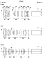
- Sectional drawing which shows the lens structure of the zoom lens for projection which concerns on Example 1 of this invention.
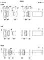
- Sectional drawing which shows the lens structure of the zoom lens for projection which concerns on Example 2 of this invention.
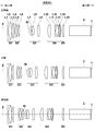
- Sectional drawing which shows the lens structure of the zoom lens for projection which concerns on Example 3 of this invention.
- Sectional drawing which shows the lens structure of the zoom lens for projection which concerns on Example 4 of this invention.
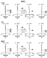
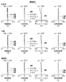
- (A) to (L) are aberration diagrams of the projection zoom lens according to Example 1 described above.
- (A) to (L) are aberration diagrams of the projection zoom lens according to Example 2 described above.
- (A) to (L) are aberration diagrams of the projection zoom lens according to Example 3 described above.
- (A) to (L) are aberration diagrams of the projection zoom lens according to Example 4 described above.
- 1 is a schematic configuration diagram showing a projection display device according to an embodiment of the present invention. Schematic block diagram showing a projection display apparatus according to another embodiment of the present invention.
- FIG. 1 shows the movement position of each lens group at the wide-angle end and the telephoto end, and the intermediate position when the zooming lens for projection according to Embodiment 1 of the present invention is zoomed. This manner of illustration is common to FIGS.
- FIG. 2 to 4 are cross-sectional views showing other configuration examples according to the embodiment of the present invention, which respectively correspond to projection zoom lenses according to Examples 2 to 4 described later. All of these projection zoom lenses have a five-group configuration. Since these projection zoom lenses have the same basic configuration as that of the first embodiment except for the part specifically described, the embodiment will be described below mainly using the configuration shown in FIG. 1 as an example. .
- the projection zoom lens according to the present embodiment can be mounted on a projection display device for projecting digital images used in movie theaters, and projects image information displayed on a light valve onto a screen, for example. It can be used as a projection lens.
- FIG. 1 shows glass blocks 2 and 1 such as a color synthesis prism (including filters) on the assumption that the left side of the drawing is an enlargement side and the right side is a reduction side and is mounted on a projection display device. Yes. The same applies to FIGS. 2 to 4 below.
- the image display surface of the light valve is disposed so as to be positioned on the reduction side surface of the glass block 1, for example.
- a light beam given image information on the image display surface is incident on the projection zoom lens through the glass blocks 2 and 1 and is arranged in the left direction in the figure by the projection zoom lens. Is projected on a screen (not shown).
- a light beam from a light source is separated into three primary colors by a color separation optical system, and three light valves are provided for each primary color. It may be arranged so that a full color image can be displayed.
- the projection zoom lens according to the present embodiment includes a first lens group G1 having a positive refractive power that is disposed closest to the enlargement side and is fixed at the time of zooming, and a reduction after the first lens group G1.
- a third lens group G3, a fourth lens group G4 having a positive refracting power which is arranged on the reduction side next to the third lens group G3 and moves at the time of zooming, and is arranged on the most reduction side and at the time of zooming
- the fifth lens group G5 having a positive refractive power fixed to the lens is a substantial lens group, and the reduction side is configured to be telecentric.
- the lens group configuration described above is common to the first to fourth embodiments.
- the projection zoom lens is configured to perform focusing by moving the first lens group G1.
- the first lens group G1 includes three lenses (first lens L1 to third lens L3), and the second lens group G2 includes three lenses (fourth lens L4 to sixth lens). L6), and the third lens group G3 includes three lenses (seventh lens L7 to ninth lens L9) and an aperture stop St disposed on the enlargement side thereof, and the fourth lens group G4 includes five lenses. (The tenth lens L10 to the fourteenth lens L14), and the fifth lens group G5 includes one lens (the fifteenth lens L15).
- the number of lenses constituting each lens group is not necessarily limited to the example shown in FIG.
- the aperture stop St arranged in the third lens group G3 is configured to move integrally with the lens of the third lens group G3. This point is common to the first to fourth embodiments.
- the aperture stop St is a variable stop that changes the aperture diameter (aperture diameter) in accordance with zooming in order to keep the numerical aperture of the zoom lens constant in the entire zooming region.
- such an aperture stop St may be arranged outside the lens constituting the moving lens group as in the present embodiment, or constitute the moving lens group. It may be arranged between the lenses, or may be configured to move along the optical axis Z independently of the moving lens group.
- the projection zoom lens according to the present embodiment includes a first lens group G1 having a positive refractive power that is fixed at the time of zooming, and a zoom lens disposed on the reduction side of the first lens group G1.
- a plurality of moving lens groups (second lens group G2, third lens group G3, and fourth lens group G4) that move, and an aperture stop St disposed in the third lens group G3 that is one moving lens group
- the numerical aperture is set so as to be constant in the entire zoom region, so that both the lens group on the most reduction side and the aperture stop arranged on the enlargement side are changed.
- the overall length of the zoom lens and the lens diameter of the first lens group G1 can be reduced. it can.
- the amount of movement between the wide-angle end and the telephoto end of the fourth lens group G4 which is the most reducing side moving lens group is mr, and the focal length of the entire system at the wide-angle end is fw.
- the following conditional expression 0.3 ⁇ mr / fw (1) Is satisfied. Thereby, the effect of further reducing the overall length of the zoom lens and the lens diameter of the first lens group G1 can be obtained.
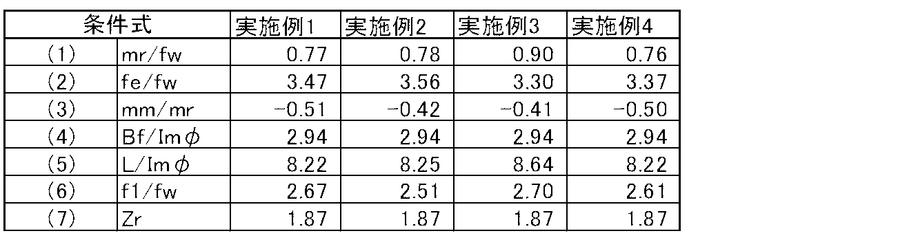
- Table 9 summarizes the values of the conditions defined by conditional expression (1) and conditional expressions (2) to (7) described later (that is, character expression portions) for each of Examples 1 to 4.
- the fifth lens group G5 which is the final lens group disposed on the most reduction side, has a positive refractive power and is fixed at the time of zooming. Then, if the focal length of the fifth lens group G5 is fe and the focal length of the entire system at the wide angle end is fw, the following conditional expression 2.0 ⁇ fe / fw ⁇ 7.0 (2) Is satisfied. As a result, spherical aberration can be corrected satisfactorily, and the zoom lens can be made compact by reducing the lens diameter of the first lens group G1, and further spherical aberration at the telephoto end can be kept small. . The reason is as described in detail above.
- the amount of movement between the wide-angle end and the telephoto end of the second lens group G2, which is the most magnifying side moving lens group, is mm, and the most reducing side moving lens group.
- the back focus (air conversion distance) on the reduction side of the entire system at the wide angle end is Bf
- the maximum effective image circle diameter (image circle diameter) on the reduction side is Im ⁇
- the projection distance is infinite.
- L be the distance on the optical axis from the most magnified lens surface at the distance (magnification side lens surface of the first lens L1) to the most demagnification side lens surface (reduction side lens surface of the fifteenth lens L15).
- the projection zoom lens according to the present embodiment can have a sufficiently long back focus.
- the reason is as described in detail above. Specific values of the back focus for each embodiment will be shown later in the table. The above effect becomes more remarkable when the conditional expression (4 ') is further satisfied within the range defined by the conditional expression (4).
- the projection zoom lens of the present embodiment can be reduced in size by reducing the overall length. This effect becomes more prominent when the conditional expression (5 ') is further satisfied within the range defined by the conditional expression (5), and in that case, chromatic aberration can be corrected well. The reason is as described in detail above.
- the projection zoom lens according to the present embodiment can ensure a high zoom ratio and expand the usable range.
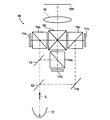
- FIG. 9 is a schematic configuration diagram showing a part of a projection display apparatus according to an embodiment of the present invention.
- the projection display device shown in FIG. 9 includes reflective display elements 11a to 11c as light valves corresponding to each color light, dichroic mirrors 12 and 13 for color separation, and a cross dichroic prism 14 for color composition.
- an illumination optical system 10 having a total reflection mirror 18 for deflecting the optical path and polarization separation prisms 15a to 15c.
- a light source 17 that emits white light L is disposed in front of the dichroic mirror 12.
- White light L emitted from the light source 17 is decomposed into three colored light beams (G light, B light, and R light) by the dichroic mirrors 12 and 13.
- the separated color light beams pass through the polarization separation prisms 15a to 15c, enter the reflective display elements 11a to 11c corresponding to the respective color light beams, are optically modulated, and are color-synthesized by the cross dichroic prism 14.
- the light enters the projection zoom lens 19 according to the embodiment of the present invention. Therefore, an optical image by the incident light is projected on the screen 100 by the projection zoom lens 19.
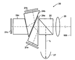
- FIG. 10 is a schematic configuration diagram showing a part of a projection display apparatus according to another embodiment of the present invention.
- the projection display apparatus shown in FIG. 10 includes reflective display elements 21a to 21c as light valves corresponding to each color light, TIR (Total Internal Reflection) prisms 24a to 24c for color separation and color synthesis, An illumination optical system 20 having a separation prism 25 is provided.
- a light source 27 that emits white light L is disposed in front of the polarization separation prism 25.
- the white light L emitted from the light source 27 passes through the polarization separation prism 25 and is then decomposed into three colored light beams (G light, B light, and R light) by the TIR prisms 24a to 24c.
- the separated color light beams are incident on the corresponding reflective display elements 21a to 21c to be light-modulated, and again travel through the TIR prisms 24a to 24c in the opposite direction to be color-combined, and then pass through the polarization separation prism 25.
- the light enters the projection zoom lens 29 according to the embodiment of the present invention. Therefore, an optical image by the incident light is projected on the screen 100 by the projection zoom lens 29.
- the reflective display elements 11a to 11c and 21a to 21c for example, reflective liquid crystal display elements, DMD, and the like can be used.
- 9 and 10 show an example in which a reflective display element is used as a light valve.
- the light valve provided in the projection display device of the present invention is not limited to this, and a transmissive liquid crystal display element, etc.
- a transmissive display element may be used.
- FIG. 1 shows the arrangement of lens groups at the wide-angle end and the telephoto end of the projection zoom lens according to the first embodiment, and at an intermediate position therebetween. Since the detailed description of FIG. 1 is as described above, the redundant description is omitted here unless particularly necessary.
- the first lens group G1 has a negative refractive power arranged in order from the enlargement side (hereinafter simply referred to as “negative” or “positive” regarding the lens).
- the first lens L1, the positive second lens L2, and the positive third lens L3 are composed of three lenses.
- the second lens group G2 includes three lenses, a negative fourth lens L4, a negative fifth lens L5, and a positive sixth lens L6, which are arranged in order from the magnification side.
- the third lens group G3 includes an aperture stop St that is a variable stop, a negative seventh lens L7, a positive eighth lens L8, and a positive ninth lens L9, which are arranged in order from the enlargement side. It consists of a lens.
- the fourth lens group G4 includes a positive tenth lens L10, a negative eleventh lens L11, a positive twelfth lens L12, a positive thirteenth lens L13, and a negative tenth lens, which are arranged in order from the magnification side. It consists of five lenses of 14 lenses L14.
- the fifth lens group G5 includes one positive fifteenth lens L15.
- the first lens L1 and the second lens L2 are cemented, the fifth lens L5 and the sixth lens L6 are cemented, and the eleventh lens L11 and the twelfth lens L12 are also cemented.
- Table 1 shows basic lens data of the projection zoom lens of Example 1.
- the glass blocks 2 and 1 are also shown.
- the Ri column indicates the radius of curvature of the i-th surface
- the Di column indicates the surface spacing on the optical axis Z between the i-th surface and the i + 1-th surface.
- the d-line (wavelength 587.6 nm) of the j-th (j 1, 2, 3,.
- the ⁇ dj column indicates the Abbe number of the j-th component with respect to the d-line.
- the values of the radius of curvature R and the surface interval D in Table 1 are values normalized with the focal length of the entire system of the projection zoom lens at the wide angle end as 10.00. In Table 1, values rounded to a predetermined digit are shown. The sign of the radius of curvature is positive when the surface shape is convex on the enlargement side and negative when the surface shape is convex on the reduction side.
- the interval between the fourth lens group G4 and the fifth lens group G5 is a variable interval that changes at the time of zooming.
- DD is the surface number on the front side of the interval.
- DD5 DD10, DD17, DD26.
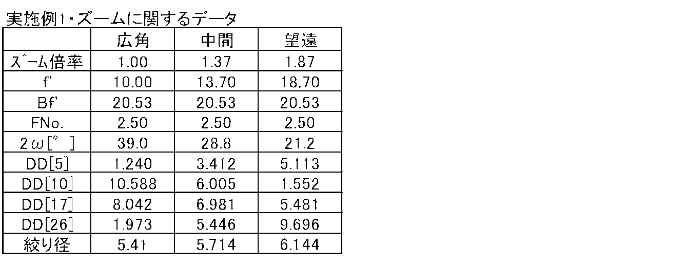
- Table 2 shows the focal length f of the entire system at the wide-angle end, the intermediate position, and the telephoto end, the back focus Bf, and the variable intervals DD5, DD10, and DD17 when the projection zoom lens according to the first embodiment performs zooming.
- DD26 and the aperture diameter of the aperture stop St indicate diameter.
- These numerical values are also values obtained by standardizing the focal length of the entire system at the wide angle end as 10.00, and these are values when the projection distance is infinite.
- Table 2 also shows the zoom magnification of the zoom lens of Example 1 (the lens at the wide-angle end is set to 1.00), the F number (numerical aperture) Fno.
- the total angle of view 2 ⁇ (in degrees) is also shown.
- the F number is kept constant at 2.5, which is sufficiently smaller than 3.0, through the wide angle end, the intermediate position, and the telephoto end. The same applies to Examples 2 to 4 described later.
- Table 9 shows the values of the conditions defined by the conditional expressions (1) to (7) (that is, the character expression part) for each of Examples 1 to 4. As shown here, the conditional expressions (1) to (7) are all satisfied in the first embodiment. The same applies to the other Examples 2 to 4. Further, as shown in Table 9, in all of Examples 1 to 4, a high zoom ratio Zr of 1.87 is secured.
- Table 10 shows main specifications in Examples 1 to 4.
- f2, f3, and f4 are focal lengths of the second lens group G3, the third lens group G3, and the fourth lens group G4, respectively.
- FIGS. 5A to 5D respectively show spherical aberration, astigmatism, distortion (distortion aberration) and lateral chromatic aberration (chromatic aberration of magnification) at the wide-angle end of the projection zoom lens of Example 1.
- the figure is shown.
- (E) to (H) in the same figure show aberration diagrams of spherical aberration, astigmatism, distortion, and lateral chromatic aberration at the intermediate position of the projection zoom lens of Example 1, respectively.
- (I) to (L) in the same figure show aberration diagrams of spherical aberration, astigmatism, distortion, and lateral chromatic aberration at the telephoto end of the projection zoom lens of Example 1, respectively.
- the distortion is suppressed within about 2% in the entire zooming region. This is almost the same in the other Examples 2 to 4.
- the aberration diagrams in FIGS. 5A to 5L are based on the d-line, but in the spherical aberration diagram, the C-line (wavelength 656.3 nm) and the F-line (wavelength wavelength 486.1 nm). Are also shown, and the chromatic aberration diagram for magnification shows aberrations for the C-line and F-line.
- aberrations in the sagittal direction and the tangential direction are indicated by a solid line and a broken line, respectively.
- Example 1 The symbols, meanings, and description methods of the lens group arrangement diagram, table, and aberration diagram of Example 1 described above are basically the same for the following Examples 2 to 4 unless otherwise specified.
- the lens group arrangement diagram (FIG. 1) of Example 1 described above is at the wide-angle end, the intermediate position, and the telephoto end, and the aberration diagram is at the wide-angle end, the intermediate position, and the telephoto end. The same applies to Examples 2 to 4.
- FIG. 2 shows the arrangement of the lens groups at the wide-angle end and the telephoto end of the projection zoom lens according to the second embodiment, and at an intermediate position therebetween.
- the first lens group G1 includes three elements, a negative first lens L1, a positive second lens L2, and a positive third lens L3, which are arranged in order from the enlargement side. It consists of a single lens.
- the second lens group G2 includes three lenses, a negative fourth lens L4, a negative fifth lens L5, and a positive sixth lens L6, which are arranged in order from the magnification side.
- the third lens group G3 includes an aperture stop St that is a variable stop, a negative seventh lens L7, a positive eighth lens L8, and a positive ninth lens L9, which are arranged in order from the enlargement side. It consists of a lens.
- the fourth lens group G4 includes a positive tenth lens L10, a negative eleventh lens L11, a positive twelfth lens L12, a positive thirteenth lens L13, and a negative tenth lens, which are arranged in order from the magnification side. It consists of five lenses of 14 lenses L14.
- the fifth lens group G5 includes one positive fifteenth lens L15.
- the first lens L1 and the second lens L2 are cemented, the fifth lens L5 and the sixth lens L6 are cemented, the seventh lens L7 and the eighth lens L8 are cemented, and the eleventh lens L11 and the twelfth lens L12. Are also joined.
- Table 3 shows basic lens data of the projection zoom lens of Example 2.
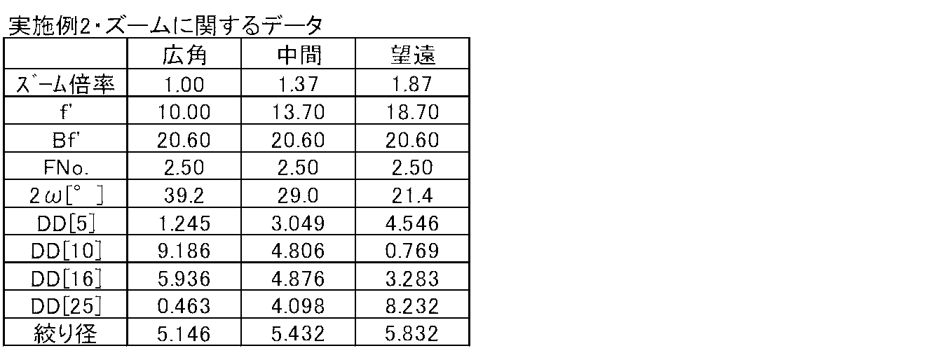
- Table 4 shows the specifications at the wide-angle end, the intermediate position, and the telephoto end when the zoom lens for projection according to the second embodiment is zoomed in the same manner as in Table 2.
- FIGS. 6A to 6L show aberration diagrams of the projection zoom lens of Example 2.
- FIG. 3 shows the arrangement of the lens groups at the wide-angle end and the telephoto end of the zoom lens for projection according to the third embodiment, and at an intermediate position therebetween.
- the first lens group G1 includes three elements, a negative first lens L1, a positive second lens L2, and a positive third lens L3, which are arranged in order from the enlargement side. It consists of a single lens.
- the second lens group G2 includes three lenses, a negative fourth lens L4, a negative fifth lens L5, and a positive sixth lens L6, which are arranged in order from the magnification side.
- the third lens group G3 includes an aperture stop St that is a variable stop, a negative seventh lens L7, a positive eighth lens L8, and a positive ninth lens L9, which are arranged in order from the enlargement side. It consists of a lens.
- the fourth lens group G4 includes a positive tenth lens L10, a negative eleventh lens L11, a positive twelfth lens L12, a positive thirteenth lens L13, and a negative tenth lens, which are arranged in order from the magnification side. It consists of five lenses of 14 lenses L14.
- the fifth lens group G5 includes one positive fifteenth lens L15.
- the first lens L1 and the second lens L2 are cemented, the fifth lens L5 and the sixth lens L6 are cemented, the seventh lens L7 and the eighth lens L8 are cemented, and the eleventh lens L11 and the twelfth lens L12. Are also joined.
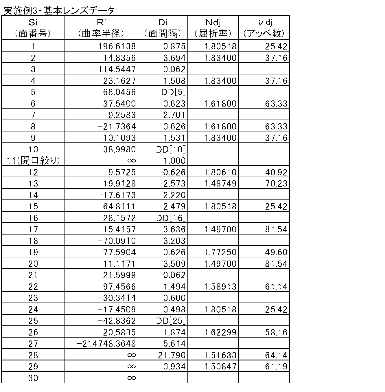
- Table 5 shows basic lens data of the projection zoom lens of Example 3.
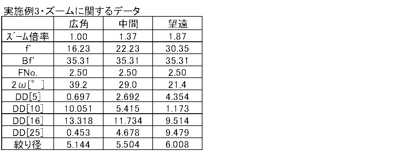
- Table 6 shows the specifications at the wide-angle end, the intermediate position, and the telephoto end when the zoom lens for projection of Example 3 is zoomed in the same manner as Table 2.
- FIGS. 7A to 7L show aberration diagrams of the projection zoom lens of Example 3.
- FIG. 4 shows the arrangement of the lens groups at the wide-angle end and the telephoto end of the projection zoom lens according to the fourth embodiment, and at an intermediate position therebetween.
- the first lens group G1 includes three elements, a negative first lens L1, a positive second lens L2, and a positive third lens L3, which are arranged in order from the enlargement side. It consists of a single lens.
- the second lens group G2 includes three lenses, a negative fourth lens L4, a negative fifth lens L5, and a positive sixth lens L6, which are arranged in order from the magnification side.
- the third lens group G3 includes an aperture stop St that is a variable stop, a negative seventh lens L7, a positive eighth lens L8, and a positive ninth lens L9, which are arranged in order from the enlargement side. It consists of a lens.
- the fourth lens group G4 includes a positive tenth lens L10, a negative eleventh lens L11, a positive twelfth lens L12, a positive thirteenth lens L13, and a negative tenth lens, which are arranged in order from the magnification side. It consists of five lenses of 14 lenses L14.
- the fifth lens group G5 includes one positive fifteenth lens L15.
- the first lens L1 and the second lens L2 are cemented, the fifth lens L5 and the sixth lens L6 are cemented, and the eleventh lens L11 and the twelfth lens L12 are also cemented.
- Table 7 shows basic lens data of the projection zoom lens of Example 4.
- Table 8 shows the specifications at the wide-angle end, the intermediate position, and the telephoto end when the zoom lens for projection according to the fourth embodiment performs zooming in the same manner as Table 2.
- FIGS. 8A to 8L show aberration diagrams of the projection zoom lens of Example 4, respectively.
- the projection display device of the present invention is not limited to the above-described configuration.
- the light valve used and the optical member used for light beam separation or light beam synthesis are not limited to the above-described configuration. Various modifications can be made.
Landscapes
- Physics & Mathematics (AREA)
- General Physics & Mathematics (AREA)
- Optics & Photonics (AREA)
- Nonlinear Science (AREA)
- Lenses (AREA)
- Projection Apparatus (AREA)
Abstract
【課題】投写用ズームレンズにおいて、開口数を全変倍領域において一定とし、また全長や、最も拡大側のレンズ群のレンズ径を小さくする。 【解決手段】最も拡大側に配置されて変倍の際に固定されている正の屈折力を有する第1レンズ群(G1)と、この第1レンズ群(G1)より縮小側に配置されて変倍の際に移動する少なくとも2つの移動レンズ群(G2~G4)と、隣り合う移動レンズ群同士の間、または1つの移動レンズ群内に配された開口絞り(St)とを有する投写用ズームレンズにおいて、その開口数が全変倍領域において一定となるように設定する。
Description
本発明はズームレンズに関し、特に、投写型表示装置に適用される投写用ズームレンズに関するものである。
また本発明は、そのような投写用ズームレンズを備えた投写型表示装置に関するものである。
従来、液晶表示素子やDMD(デジタル・マイクロミラー・デバイス:登録商標)等のライトバルブを用いた投写型表示装置が広く普及している。また、近年、映画館等においては、このような投写型表示装置であって、大画面に適用し得る、より高精細な画像を映出し得るようにしたものも利用されつつある。
上述した映画館等での利用に供される投写型表示装置においては、各原色用に3つのライトバルブを配設して、光源からの光束を色分離光学系により3原色に分離し、各ライトバルブを経由した後、色合成光学系により合成して投写する3板方式が採用されていることから、長いバックフォーカスと良好なテレセントリック性を有することが求められている。
また、映画館等での利用に供される投写型表示装置においては、映画館やホールごとに異なる投射距離とスクリーンサイズに応じて、さらには、表示画像のアスペクト比(シネスコサイズ、ビスタサイズなど)に応じて、スクリーンサイズに表示画像のサイズを適合させるために、投写用レンズとして高変倍比のズームレンズが求められるようになってきている。
また、そのような投写用ズームレンズを、上述したサイズ適合のために変倍させた際に、表示画像の明るさが変わってしまうことを防止するため、この種のズームレンズには、その開口数(以下、「Fナンバー」ということもある)を全変倍領域において一定に保つ機能が求められることが多い。
さらに、シネマスクリーンのデジタル化の加速に伴い、投写型表示装置の小型化、低価格化が進み、投写用ズームレンズにも、上述したバックフォーカスやテレセントリック性、高変倍比に関する要望と共に、小型化、低コスト化が求められる傾向にある。
特許文献1および2には、開口数を全変倍領域において一定に保つようにした投写用ズームレンズが示されている。
しかし、特許文献1や2に示された投写用ズームレンズは、開口数を一定に保つ等のために開口絞りよりも拡大側のレンズ群を移動させ、開口絞りおよびそれよりも縮小側のレンズ群は固定としておくため、高変倍比を実現しようとすると、全長や、最も拡大側のレンズ群のレンズ径が大きくなってしまうため、小型化の要求に応えることができない。また、全長やレンズ径が大きくなることから、光学系のコストアップに繋がり、低コスト化の要求にも応えることができない。
本発明は上記の事情に鑑みてなされたものであり、開口数を全変倍領域において一定とすることができ、そして全長や、最も拡大側のレンズ群のレンズ径を小さくすることができる投写用ズームレンズおよび、投写型表示装置を提供することを目的とするものである。
本発明による投写用ズームレンズは、
最も拡大側に配置されて変倍の際に固定されている正の屈折力を有する第1レンズ群と、
この第1レンズ群より縮小側に配置されて変倍の際に移動する少なくとも2つの移動レンズ群と、
隣り合う移動レンズ群同士の間、または1つの移動レンズ群内に配された開口絞りとを有する投写用ズームレンズにおいて、
該ズームレンズの開口数が全変倍領域において一定となるように設定され、
縮小側がテレセントリックとなるように構成されていることを特徴とするものである。
最も拡大側に配置されて変倍の際に固定されている正の屈折力を有する第1レンズ群と、
この第1レンズ群より縮小側に配置されて変倍の際に移動する少なくとも2つの移動レンズ群と、
隣り合う移動レンズ群同士の間、または1つの移動レンズ群内に配された開口絞りとを有する投写用ズームレンズにおいて、
該ズームレンズの開口数が全変倍領域において一定となるように設定され、
縮小側がテレセントリックとなるように構成されていることを特徴とするものである。
なお、上記の「1つの移動レンズ群内に配された」とは、その移動レンズ群を構成する最も拡大側のレンズおよび最も縮小側のレンズの間に配置されることだけではなく、最も拡大側のレンズより拡大側、あるいは最も縮小側のレンズより縮小側に配置されることも示すものとする。
また、上記の「縮小側がテレセントリック」とは、縮小側の像面の任意の点に集光する光束の断面において上側の最大光線と下側の最大光線との二等分角線が光軸と平行に近い状態を指すものであり、完全にテレセントリックな場合、すなわち前記二等分角線が光軸に対して完全に平行な場合に限るものではなく、多少の誤差がある場合をも含むものを意味する。ここで多少の誤差がある場合とは、光軸に対する前記二等分角線の傾きが±3°の範囲内の場合である。
本発明の投写用ズームレンズにおいては、最も縮小側の移動レンズ群の広角端と望遠端との間の移動量をmr、広角端における全系の焦点距離をfwとして、下記条件式
0.3<mr/fw… (1)
が満たされていることが望ましい。
0.3<mr/fw… (1)
が満たされていることが望ましい。
なお、この条件式(1)が規定している条件については、下式
0.5<mr/fw… (1’)
が満たされていることがより望ましい。
0.5<mr/fw… (1’)
が満たされていることがより望ましい。
また本発明の投写用ズームレンズにおいては、
最も縮小側に配置された最終レンズ群が、正の屈折力を有して変倍の際に固定されているものとされた上で、最終レンズ群の焦点距離をfe、広角端における全系の焦点距離をfwとして、下記条件式
2.0<fe/fw<7.0… (2)
が満たされていることが望ましい。
最も縮小側に配置された最終レンズ群が、正の屈折力を有して変倍の際に固定されているものとされた上で、最終レンズ群の焦点距離をfe、広角端における全系の焦点距離をfwとして、下記条件式
2.0<fe/fw<7.0… (2)
が満たされていることが望ましい。
なお、この条件式(2)が規定している条件については、下式
3.0<fe/fw<5.0… (2’)
が満たされていることがより望ましい。
3.0<fe/fw<5.0… (2’)
が満たされていることがより望ましい。
また本発明の投写用ズームレンズは、
前述のように最も拡大側に配置されて変倍の際に固定されている正の屈折力を有する第1レンズ群と、最も縮小側に配置されて変倍の際に固定されている正の屈折力を有する最終レンズ群と、前記第1レンズ群と前記最終レンズ群との間に配置されて変倍の際に移動する複数のレンズ群とから実質的に構成されており、
前記変倍の際に移動する複数のレンズ群のうち、最も拡大側のレンズ群が負の屈折力を有し、最も縮小側のレンズ群が正の屈折力を有し、
最も拡大側の移動レンズ群の広角端と望遠端との間の移動量をmm、最も縮小側の移動レンズ群の広角端と望遠端との間の移動量をmrとして、下記条件式
-1.0<mm/mr<-0.2… (3)
が満たされていることが望ましい。
前述のように最も拡大側に配置されて変倍の際に固定されている正の屈折力を有する第1レンズ群と、最も縮小側に配置されて変倍の際に固定されている正の屈折力を有する最終レンズ群と、前記第1レンズ群と前記最終レンズ群との間に配置されて変倍の際に移動する複数のレンズ群とから実質的に構成されており、
前記変倍の際に移動する複数のレンズ群のうち、最も拡大側のレンズ群が負の屈折力を有し、最も縮小側のレンズ群が正の屈折力を有し、
最も拡大側の移動レンズ群の広角端と望遠端との間の移動量をmm、最も縮小側の移動レンズ群の広角端と望遠端との間の移動量をmrとして、下記条件式
-1.0<mm/mr<-0.2… (3)
が満たされていることが望ましい。
なお、この条件式(3)が規定している条件については、下式
-0.7<mm/mr<-0.3… (3’)
が満たされていることがより望ましい。
-0.7<mm/mr<-0.3… (3’)
が満たされていることがより望ましい。
また本発明の投写用ズームレンズにおいては、開口絞りとして、変倍の全範囲に亘って開口数が一定となるように開口径(絞り径)を変化させるものが用いられていることが望ましい。
また本発明の投写用ズームレンズにおいては、広角端における全系の縮小側のバックフォーカス(空気換算距離)をBf、縮小側における最大有効像円直径(イメージサークル径)をImφ、投写距離無限遠時の最も拡大側のレンズ面から最も縮小側のレンズ面までの光軸上の距離をLとして、下記条件式
2.0<Bf/Imφ… (4)
L/Imφ<12… (5)
が満たされていることが望ましい。
2.0<Bf/Imφ… (4)
L/Imφ<12… (5)
が満たされていることが望ましい。
なお、この条件式(4)が規定している条件については、下式
2.5<Bf/Imφ… (4’)
が満たされていることがより望ましい。
2.5<Bf/Imφ… (4’)
が満たされていることがより望ましい。
また、この条件式(5)が規定している条件については、下式
7<L/Imφ<11… (5’)
が満たされていることがより望ましい。
7<L/Imφ<11… (5’)
が満たされていることがより望ましい。
さらに本発明の投写用ズームレンズにおいては、第1レンズ群の焦点距離をf1、広角端における全系の焦点距離をfwとして、条件式
1.0<f1/fw<5.0… (6)
が満たされていることが望ましい。
1.0<f1/fw<5.0… (6)
が満たされていることが望ましい。
なお、上記条件式(6)が規定している条件については、下式
2.0<f1/fw<4.0… (6’)
が満たされていることがより望ましい。
2.0<f1/fw<4.0… (6’)
が満たされていることがより望ましい。
また本発明の投写用ズームレンズは、拡大側から順に配置された、前記第1レンズ群と、変倍の際に移動する負の屈折力を有する第2レンズ群と、変倍の際に移動する負の屈折力を有する第3レンズ群と、変倍の際に移動する正の屈折力を有する第4レンズ群と、変倍の際に固定されている正の屈折力を有する第5レンズ群とから実質的に構成されていることが望ましい。
さらに本発明の投写用ズームレンズにおいては、広角端に対する望遠端の変倍比をZrとして、条件式
1.4<Zr… (7)
が満たされていることが望ましい。
1.4<Zr… (7)
が満たされていることが望ましい。
また、上記条件式(7)が規定している条件については、下式
1.6<Zr… (7’)
が満たされていることがより望ましい。
1.6<Zr… (7’)
が満たされていることがより望ましい。
なお、本発明の投写用ズームレンズにおいて、各レンズ群を構成するレンズには接合レンズが用いられてもよいが、接合レンズはn枚の貼り合わせで構成されていれば、n枚のレンズとして数えるものとする。
他方、本発明による投写型表示装置は、光源と、該光源からの光が入射するライトバルブと、該ライトバルブにより光変調された光による光学像をスクリーン上に投写する投写用ズームレンズとを備え、この投写用ズームレンズとして上述した本発明による投写用ズームレンズが適用されたことを特徴とするものである。
本発明の投写用ズームレンズは、最も拡大側に配置されて変倍の際に固定されている正の屈折力を有する第1レンズ群と、この第1レンズ群より縮小側に配置されて変倍の際に移動する少なくとも2つの移動レンズ群と、隣り合う移動レンズ群同士の間、または1つの移動レンズ群内に配された開口絞りとを有する投写用ズームレンズにおいて、開口数が全変倍領域において一定となるように設定されたものであるので、最も縮小側のレンズ群と、その拡大側に配置された開口絞りの双方を、変倍時に共に固定しておいて開口数の一定化を図った引用文献1に記載の投写用ズームレンズと比べると、全長や、最も拡大側のレンズ群のレンズ径を小さくすることができる。それにより本発明の投写用ズームレンズは、設置のための制限が厳しくなったり、コストが高くなることを防止できる。
また本発明の投写用ズームレンズにおいて特に、前述した条件式
0.3<mr/fw… (1)
が満たされている場合は、それにより、ズームレンズの全長や、最も拡大側のレンズ群のレンズ径をさらに小さくする効果が得られる。
0.3<mr/fw… (1)
が満たされている場合は、それにより、ズームレンズの全長や、最も拡大側のレンズ群のレンズ径をさらに小さくする効果が得られる。
以上の効果は、条件式(1)が規定する範囲内でさらに下式
0.5<mr/fw… (1’)
が満たされている場合は、より顕著なものとなる。
0.5<mr/fw… (1’)
が満たされている場合は、より顕著なものとなる。
また本発明の投写用ズームレンズにおいて、
最も縮小側に配置された最終レンズ群が、正の屈折力を有して変倍の際に固定されているものとされた上で、最終レンズ群の焦点距離をfe、広角端における全系の焦点距離をfwとして、前記条件式
2.0<fe/fw<7.0… (2)
が満たされている場合は、以下の効果を得ることができる。
最も縮小側に配置された最終レンズ群が、正の屈折力を有して変倍の際に固定されているものとされた上で、最終レンズ群の焦点距離をfe、広角端における全系の焦点距離をfwとして、前記条件式
2.0<fe/fw<7.0… (2)
が満たされている場合は、以下の効果を得ることができる。
すなわち、fe/fwの値が2.0以下になると、球面収差の補正が困難になり、また拡大側のレンズ径が大きくなってズームレンズが大型になりやすいが、fe/fwの値が2.0を上回っていればそのような問題を回避して、球面収差を良好に補正可能となり、そして拡大側のレンズ径を小さくしてズームレンズを小型に形成可能となる。
また、fe/fwの値が7.0以上になると、望遠端での球面収差が大きくなりがちであるが、fe/fwの値が7.0を下回っていればそのような問題を回避して、望遠端での球面収差を小さく抑えることが可能になる。
以上の効果は、条件式(2)が規定する範囲内でさらに下式
3.0<fe/fw<5.0… (2’)
が満たされている場合は、より顕著なものとなる。
3.0<fe/fw<5.0… (2’)
が満たされている場合は、より顕著なものとなる。
また本発明の投写用ズームレンズにおいて、
最も縮小側に配置されて変倍の際に固定されている正の屈折力を有する最終レンズ群と、前記第1レンズ群と前記最終レンズ群との間に配置されて変倍の際に移動する複数のレンズ群とから実質的に構成され、
前記変倍の際に移動する複数のレンズ群のうち、最も拡大側のレンズ群が負の屈折力を有し、最も縮小側のレンズ群が正の屈折力を有し、
最も拡大側の移動レンズ群の広角端と望遠端との間の移動量をmm、最も縮小側の移動レンズ群の広角端と望遠端との間の移動量をmrとして、前記条件式
-1.0<mm/mr<-0.2… (3)
が満たされている場合は、下記の効果を得ることができる。
最も縮小側に配置されて変倍の際に固定されている正の屈折力を有する最終レンズ群と、前記第1レンズ群と前記最終レンズ群との間に配置されて変倍の際に移動する複数のレンズ群とから実質的に構成され、
前記変倍の際に移動する複数のレンズ群のうち、最も拡大側のレンズ群が負の屈折力を有し、最も縮小側のレンズ群が正の屈折力を有し、
最も拡大側の移動レンズ群の広角端と望遠端との間の移動量をmm、最も縮小側の移動レンズ群の広角端と望遠端との間の移動量をmrとして、前記条件式
-1.0<mm/mr<-0.2… (3)
が満たされている場合は、下記の効果を得ることができる。
すなわち、mm/mrの値が-1.0以下になると、変倍時の倍率色の変動が大きくなるが、mm/mrの値が-1.0を上回っていればそのような問題を回避して、変倍時の倍率色の変動を小さく抑えることができる。
また、mm/mrの値が-0.2以上になると、変倍時の像面湾曲の変動が大きくなるが、mm/mrの値が-0.2を下回っていればそのような問題を回避して、変倍時の像面湾曲の変動を小さく抑えることができる。
以上の効果は、条件式(3)が規定する範囲内でさらに下式
-0.7<mm/mr<-0.3… (3’)
が満たされている場合は、より顕著なものとなる。
-0.7<mm/mr<-0.3… (3’)
が満たされている場合は、より顕著なものとなる。
また、本発明の投写用ズームレンズにおいて特に、開口絞りとして、変倍の全範囲に亘って開口数が一定となるように開口径を変化させるものが用いられている場合は、より大きな変倍比を実現可能となる。
また、本発明の投写用ズームレンズにおいて特に、広角端における全系の縮小側のバックフォーカス(空気換算距離)をBf、縮小側における最大有効像円直径(イメージサークル径)をImφ、投写距離無限遠時の最も拡大側のレンズ面から最も縮小側のレンズ面までの光軸上の距離をLとして、前記条件式
2.0<Bf/Imφ… (4)
L/Imφ<12… (5)
が満たされている場合は、以下の効果を得ることができる。
2.0<Bf/Imφ… (4)
L/Imφ<12… (5)
が満たされている場合は、以下の効果を得ることができる。
すなわち、Bf/Imφの値が2.0以下になると、バックフォーカスが短くなって、前述したようなプリズムを挿入することが難しくなるが、Bf/Imφの値が2.0を上回っていれば、そのようなプリズムの挿入が容易になる。
以上の効果は、条件式(4)が規定する範囲内でさらに下式
2.5<Bf/Imφ… (4’)
が満たされている場合は、より顕著なものとなる。
2.5<Bf/Imφ… (4’)
が満たされている場合は、より顕著なものとなる。
一方、条件式(5)が規定するようにL/Imφの値が12を下回っていれば、ズームレンズ全長を短く抑えることができる。
この効果は、条件式(5)が規定する範囲内でさらに下式
7<L/Imφ<11… (5’)
が満たされている場合は、より顕著なものとなる。またこのL/Imφの値が7以下になると、色収差の補正が困難になるが、条件式(5’)が満たされている場合は、そのような問題を回避して、色収差を良好に補正可能となる。
7<L/Imφ<11… (5’)
が満たされている場合は、より顕著なものとなる。またこのL/Imφの値が7以下になると、色収差の補正が困難になるが、条件式(5’)が満たされている場合は、そのような問題を回避して、色収差を良好に補正可能となる。
また本発明の投写用ズームレンズにおいて特に、前記条件式
1.0<f1/fw<5.0… (6)
が満たされている場合は、以下の効果を得ることができる。
1.0<f1/fw<5.0… (6)
が満たされている場合は、以下の効果を得ることができる。
すなわち、f1/fwの値が1.0以下になると、球面収差の補正が困難になるが、f1/fwの値が1.0を上回っていればそのような問題を回避して、球面収差を良好に補正可能となる。
また、f1/fwの値が5.0以上になると、軸上色収差の補正が困難になり、また拡大側のレンズ径が大きくなるが、f1/fwの値が5.0を下回っていればそのような問題を回避して、軸上色収差を容易に補正可能となり、また拡大側のレンズ径を小さく抑えることが可能になる。
以上の効果は、条件式(6)が規定する範囲内でさらに下式
2.0<f1/fw<4.0… (6’)
が満たされている場合は、より顕著なものとなる。
2.0<f1/fw<4.0… (6’)
が満たされている場合は、より顕著なものとなる。
また、本発明の投写用ズームレンズにおいて特に前記条件式
1.4<Zr… (7)
が満たされている場合は、高変倍比を確保して、投写用ズームレンズの使用可能範囲を広げることができる。
1.4<Zr… (7)
が満たされている場合は、高変倍比を確保して、投写用ズームレンズの使用可能範囲を広げることができる。
以上の効果は、条件式(7)が規定する範囲内でさらに下式
1.6<Zr… (7’)
が満たされている場合は、より顕著なものとなる。
1.6<Zr… (7’)
が満たされている場合は、より顕著なものとなる。
なお、映画館等での利用に供される投写型表示装置に適用されるズームレンズには一般に、全変倍領域でFナンバーが3.0よりも小さい(明るい)ことが求められるが、本発明の投写用ズームレンズは、そのような要求にも応えられるものである。その具体的数値については、以下で実施例に即して説明する。
また、上述のような投写型表示装置に適用されるズームレンズには一般に、全変倍領域で歪曲収差が2%程度内に抑えられていることが求められるが、本発明の投写用ズームレンズは、そのような要求にも応えられるものである。その具体的数値については、以下で実施例に即して説明する。
他方、本発明の投写型表示装置は、投写用ズームレンズとして以上述べた通りの本発明のズームレンズが適用されたものであるので、高変倍比を確保した上で開口数を全変倍領域において一定とすることができ、またズームレンズの全長や、最も拡大側のレンズ群のレンズ径を小さくすることができることから、小型に形成可能となる。
以下、本発明の実施形態について図面を参照して詳細に説明する。まず、図1を参照して、本発明の一実施形態に係る投写用ズームレンズについて説明する。この図1は、本発明の実施例1に係る投写用ズームレンズを変倍操作させたときの広角端および望遠端、並びにそれらの中間位置における、各レンズ群の移動位置を示すものである。この図示の仕方は、図1~4において共通である。
図2~4は、本発明の実施形態に係る別の構成例を示す断面図であり、それぞれ後述の実施例2~4に係る投写用ズームレンズに対応している。これらの投写用ズームレンズは全て5群構成のものである。これらの投写用ズームレンズは特に説明する部分以外、基本的な構成が実施例1のものと共通しているので、以下では、主に図1に示す構成を例に取って実施形態を説明する。
本実施形態の投写用ズームレンズは、映画館等で用いられるデジタル映像を映出するための投写型表示装置に搭載可能なものであり、例えばライトバルブに表示された画像情報をスクリーンへ投写する投写レンズとして使用可能である。図1では、図の左側を拡大側、右側を縮小側とし、投写型表示装置に搭載される場合を想定して、色合成プリズム(フィルタ類を含む)等のガラスブロック2、1を示している。これは、以下の図2~4においても同様である。なおライトバルブの画像表示面は、例えばガラスブロック1の縮小側の面に位置するように配される。
投写型表示装置においては、上記画像表示面で画像情報を与えられた光束が、ガラスブロック2、1を介して投写用ズームレンズに入射され、該投写用ズームレンズにより図中左側方向に配置されるスクリーン(不図示)上に拡大投写される。
なお上の説明では、ガラスブロック2の縮小側の面の位置と画像表示面の位置とが一致した例を示しているが、必ずしもこれに限定されない。また上の説明では、1つの画像表示面のみについて説明しているが、投写型表示装置において、光源からの光束を色分離光学系により3原色に分離し、各原色用に3つのライトバルブを配設して、フルカラー画像を表示できるように構成してもよい。
本実施形態に係る投写用ズームレンズは、最も拡大側に配置されて変倍の際に固定されている正の屈折力を有する第1レンズ群G1と、この第1レンズ群G1の次に縮小側に配置されて変倍時に移動する負の屈折力を有する第2レンズ群G2と、この第2レンズ群G2の次に縮小側に配置されて変倍時に移動する負の屈折力を有する第3レンズ群G3と、この第3レンズ群G3の次に縮小側に配置されて変倍時に移動する正の屈折力を有する第4レンズ群G4と、最も縮小側に配置されて変倍の際に固定されている正の屈折力を有する第5レンズ群G5とを実質的なレンズ群として有し、縮小側がテレセントリックとなるように構成されている。以上述べたレンズ群の構成は、実施例1~4において共通である。
そしてこの投写用ズームレンズは、第1レンズ群G1を移動させてフォーカシングを行うように構成されている。
図1に示す例では、第1レンズ群G1は3枚のレンズ(第1レンズL1~第3レンズL3)からなり、第2レンズ群G2は3枚のレンズ(第4レンズL4~第6レンズL6)からなり、第3レンズ群G3は3枚のレンズ(第7レンズL7~第9レンズL9)およびその拡大側に配置された開口絞りStからなり、第4レンズ群G4は5枚のレンズ(第10レンズL10~第14レンズL14)からなり、第5レンズ群G5は1枚のレンズ(第15レンズL15)からなる。ただし、各レンズ群を構成するレンズの枚数は、必ずしも図1に示す例に限定されるものではない。
本実施形態の投写用ズームレンズにおいては、第3レンズ群G3に配置された開口絞りStが、この第3レンズ群G3のレンズと一体で移動するように構成されている。この点は、実施例1~4において共通である。そしてこの開口絞りStは、全変倍領域でズームレンズの開口数を一定とするために、変倍に伴って開口径(絞り径)を変化させる可変絞りとされている。なお本発明の投写用ズームレンズにおいて、そのような開口絞りStは、本実施形態におけるように移動レンズ群を構成するレンズの外側に配置されていてもよいし、あるいは、移動レンズ群を構成するレンズ同士の間に配置されていてもよいし、さらには、移動レンズ群とは独立して光軸Zに沿って移動するように構成されてもよい。
本実施形態の投写用ズームレンズは、変倍の際に固定されている正の屈折力を有する第1レンズ群G1と、この第1レンズ群G1より縮小側に配置されて変倍の際に移動する複数の移動レンズ群(第2レンズ群G2、第3レンズ群G3および第4レンズ群G4)と、1つの移動レンズ群である第3レンズ群G3内に配された開口絞りStとを有する投写用ズームレンズにおいて、開口数が全変倍領域において一定となるように設定されたものであるので、最も縮小側のレンズ群と、その拡大側に配置された開口絞りの双方を、変倍時に共に固定しておいて開口数の一定化を図った引用文献1に記載の投写用ズームレンズ等と比べると、ズームレンズの全長や、第1レンズ群G1のレンズ径を小さくすることができる。
そしてこの投写用ズームレンズにおいては、最も縮小側の移動レンズ群である第4レンズ群G4の広角端と望遠端との間の移動量をmr、広角端における全系の焦点距離をfwとして、下記条件式
0.3<mr/fw… (1)
が満たされている。それにより、ズームレンズの全長や、第1レンズ群G1のレンズ径をさらに小さくする効果が得られる。
0.3<mr/fw… (1)
が満たされている。それにより、ズームレンズの全長や、第1レンズ群G1のレンズ径をさらに小さくする効果が得られる。
以上の効果は、条件式(1)が規定する範囲内でさらに前記条件式(1’)が満たされている場合は、より顕著なものとなる。
なお条件式(1)や後述する条件式(2)~(7)が規定する条件(つまり文字式の部分)の値を、実施例1~4の各々について表9にまとめて示してある。
また本実施形態の投写用ズームレンズにおいては、最も縮小側に配置された最終レンズ群である第5レンズ群G5が、正の屈折力を有して変倍の際に固定されているものとされた上で、この第5レンズ群G5の焦点距離をfe、広角端における全系の焦点距離をfwとして、下記条件式
2.0<fe/fw<7.0… (2)
が満たされている。それにより、球面収差を良好に補正可能となり、そして第1レンズ群G1のレンズ径を小さくしてズームレンズを小型に形成可能となり、さらには望遠端での球面収差を小さく抑えることが可能になる。その理由は先に詳しく説明した通りである。
2.0<fe/fw<7.0… (2)
が満たされている。それにより、球面収差を良好に補正可能となり、そして第1レンズ群G1のレンズ径を小さくしてズームレンズを小型に形成可能となり、さらには望遠端での球面収差を小さく抑えることが可能になる。その理由は先に詳しく説明した通りである。
以上の効果は、条件式(2)が規定する範囲内でさらに前記条件式(2’)が満たされている場合は、より顕著なものとなる。
また本実施形態の投写用ズームレンズにおいては、最も拡大側の移動レンズ群である第2レンズ群G2の広角端と望遠端との間の移動量をmm、最も縮小側の移動レンズ群である第4レンズ群G4の広角端と望遠端との間の移動量をmrとして、下記条件式
-1.0<mm/mr<-0.2… (3)
が満たされている。それにより、変倍時の倍率色の変動や、変倍時の像面湾曲の変動を小さく抑えることができる。その理由は先に詳しく説明した通りである。
-1.0<mm/mr<-0.2… (3)
が満たされている。それにより、変倍時の倍率色の変動や、変倍時の像面湾曲の変動を小さく抑えることができる。その理由は先に詳しく説明した通りである。
以上の効果は、条件式(3)が規定する範囲内でさらに前記条件式(3’)が満たされている場合は、より顕著なものとなる。
また本実施形態の投写用ズームレンズにおいては、広角端における全系の縮小側のバックフォーカス(空気換算距離)をBf、縮小側における最大有効像円直径(イメージサークル径)をImφ、投写距離無限遠時の最も拡大側のレンズ面(第1レンズL1の拡大側レンズ面)から最も縮小側のレンズ面(第15レンズL15の縮小側レンズ面)までの光軸上の距離をLとして、下記条件式
2.0<Bf/Imφ… (4)
L/Imφ<12… (5)
が満たされている。
2.0<Bf/Imφ… (4)
L/Imφ<12… (5)
が満たされている。
このように条件式(4)が満たされていることにより、本実施形態の投写用ズームレンズは、十分長いバックフォーカスを備え得るものとなる。その理由は先に詳しく説明した通りである。実施例毎のバックフォーカスの具体的な値については後に表において示す。以上の効果は、条件式(4)が規定する範囲内でさらに前記条件式(4’)が満たされている場合は、より顕著なものとなる。
また条件式(5)が満たされていることにより、本実施形態の投写用ズームレンズは、全長を短くして小型化を達成することができる。この効果は、条件式(5)が規定する範囲内でさらに前記条件式(5’)が満たされている場合は、より顕著なものとなり、さらにその場合は色収差を良好に補正可能となる。その理由は先に詳しく説明した通りである。
さらに本実施形態の投写用ズームレンズにおいては、第1レンズ群G1の焦点距離をf1、広角端における全系の焦点距離をfwとして、下記条件式
1.0<f1/fw<5.0… (6)
が満たされている。それにより、球面収差および軸上色収差を容易に補正し、さらには第1レンズ群G1のレンズ径を小さく抑えることが可能になる。その理由は先に詳しく説明した通りである。
1.0<f1/fw<5.0… (6)
が満たされている。それにより、球面収差および軸上色収差を容易に補正し、さらには第1レンズ群G1のレンズ径を小さく抑えることが可能になる。その理由は先に詳しく説明した通りである。
以上の効果は、条件式(6)が規定する範囲内でさらに前記条件式(6’)が満たされている場合は、より顕著なものとなる。
さらに本実施形態の投写用ズームレンズにおいては、広角端に対する望遠端の変倍比をZrとして、条件式
1.4<Zr… (7)
が満たされている。それにより本実施形態の投写用ズームレンズは、高変倍比を確保して、その使用可能範囲を拡大できるものとなる。
1.4<Zr… (7)
が満たされている。それにより本実施形態の投写用ズームレンズは、高変倍比を確保して、その使用可能範囲を拡大できるものとなる。
以上の効果は、条件式(7)が規定する範囲内でさらに前記条件式(7’)が満たされている場合は、より顕著なものとなる。
次に、本発明に係る投写型表示装置の実施形態について、図9および10を用いて説明する。図9は本発明の一実施形態に係る投写型表示装置の一部を示す概略構成図である。この図9に示す投写型表示装置は、各色光に対応したライトバルブとしての反射型表示素子11a~11cと、色分解のためのダイクロイックミラー12、13と、色合成のためのクロスダイクロイックプリズム14と、光路偏向のための全反射ミラー18と、偏光分離プリズム15a~15cを有する照明光学系10を備えている。なお、ダイクロイックミラー12の前段には、白色光Lを発する光源17が配されている。
光源17から発せられた白色光Lはダイクロイックミラー12、13により3つの色光光束(G光、B光、R光)に分解される。分解後の各色光光束はそれぞれ偏光分離プリズム15a~15cを経て、各色光光束それぞれに対応する反射型表示素子11a~11cに入射して光変調され、クロスダイクロイックプリズム14により色合成された後、本発明の実施形態に係る投写用ズームレンズ19に入射する。そこでこの入射光による光学像が投写用ズームレンズ19により、スクリーン100上に投写される。
次に図10は、本発明の別の実施形態に係る投写型表示装置の一部を示す概略構成図である。この図10に示す投写型表示装置は、各色光に対応したライトバルブとしての反射型表示素子21a~21cと、色分解および色合成のためのTIR(Total Internal Reflection)プリズム24a~24cと、偏光分離プリズム25とを有する照明光学系20を備えている。なお、偏光分離プリズム25の前段には、白色光Lを発する光源27が配されている。
光源27から発せられた白色光Lは偏光分離プリズム25を経た後、TIRプリズム24a~24cにより3つの色光光束(G光、B光、R光)に分解される。分解された各色光光束はそれぞれ対応する反射型表示素子21a~21cに入射して光変調され、再びTIRプリズム24a~24cを逆向きに進行して色合成された後、偏光分離プリズム25を透過して、本発明の実施形態に係る投写用ズームレンズ29に入射する。そこでこの入射光による光学像が投写用ズームレンズ29により、スクリーン100上に投写される。
なお、反射型表示素子11a~11c、21a~21cとしては、例えば反射型液晶表示素子やDMD等を用いることができる。図9および10では、ライトバルブとして反射型表示素子を用いた例を示したが、本発明の投写型表示装置が備えるライトバルブは、これに限られるものではなく、透過型液晶表示素子等の透過型表示素子を用いてもよい。
次に、本発明の投写用ズームレンズの具体的な実施例について説明する。
<実施例1>
図1に、実施例1の投写用ズームレンズの広角端および望遠端、並びにそれらの中間位置におけるレンズ群の配置を示す。なお、図1についての詳細な説明は先に説明した通りであるので、ここでは特に必要の無い限り重複した説明は省略する。
図1に、実施例1の投写用ズームレンズの広角端および望遠端、並びにそれらの中間位置におけるレンズ群の配置を示す。なお、図1についての詳細な説明は先に説明した通りであるので、ここでは特に必要の無い限り重複した説明は省略する。
この実施例1の投写用ズームレンズにおいて、第1レンズ群G1は、拡大側から順に配置された、負の屈折力を有する(以下、レンズに関しては単に「負の」あるいは「正の」という)第1レンズL1と、正の第2レンズL2と、正の第3レンズL3の3枚のレンズから構成されている。第2レンズ群G2は、拡大側から順に配置された、負の第4レンズL4と、負の第5レンズL5と、正の第6レンズL6の3枚のレンズから構成されている。
第3レンズ群G3は、拡大側から順に配置された、可変絞りである開口絞りStと、負の第7レンズL7と、正の第8レンズL8と、正の第9レンズL9の3枚のレンズから構成されている。
第4レンズ群G4は、拡大側から順に配置された、正の第10レンズL10と、負の第11レンズL11と、正の第12レンズL12と、正の第13レンズL13と、負の第14レンズL14の5枚のレンズから構成されている。第5レンズ群G5は、1枚の正の第15レンズL15から構成されている。
なお、第1レンズL1と第2レンズL2は接合され、第5レンズL5と第6レンズL6は接合され、第11レンズL11と第12レンズL12も接合されている。
表1に、実施例1の投写用ズームレンズの基本レンズデータを示す。ここでは、ガラスブロック2、1も含めて示している。表1において、Siの欄には最も拡大側に有る構成要素の拡大側の面を1番目として縮小側に向かうに従い順次増加するように構成要素に面番号を付したときのi番目(i=1、2、3、…)の面番号を示す。Riの欄にはi番目の面の曲率半径を示し、Diの欄にはi番目の面とi+1番目の面との光軸Z上の面間隔を示している。また、Ndjの欄には最も拡大側の構成要素を1番目として縮小側に向かうに従い順次増加するj番目(j=1、2、3、…)の構成要素のd線(波長587.6nm)に対する屈折率を示し、νdjの欄にはj番目の構成要素のd線に対するアッベ数を示している。
なお表1の曲率半径Rおよび面間隔Dの値は、広角端における投写用ズームレンズの全系の焦点距離を10.00として規格化した値である。また表1中では、所定の桁でまるめた数値を記載している。また曲率半径の符号は、面形状が拡大側に凸の場合を正、縮小側に凸の場合を負としている。
面間隔Dのうち、第1レンズ群G1と第2レンズ群G2との間隔、第2レンズ群G2と第3レンズ群G3との間隔、第3レンズ群G3と第4レンズ群G4との間隔、および第4レンズ群G4と第5レンズ群G5との間隔は、変倍時に変化する可変間隔であり、これらの間隔に相当する欄にはそれぞれ、「DD」に当該間隔の前側の面番号を付してDD5、DD10、DD17、DD26と記載している。
以上は、後述する表3、5、および7においても同様である。なお、上述した可変レンズ群間隔について、「DD」の後に続く数字は各実施例における構成要素の数に応じて変わっているが、当該間隔の前側の面番号を付して示しているのはどの表でも同じである。
ここで表2に、実施例1の投写用ズームレンズが変倍する際の広角端、中間位置、望遠端における全系の焦点距離fと、バックフォーカスBfと、上記可変間隔DD5、DD10、DD17、DD26の値と、開口絞りStの絞り径(開口径:直径を示す)とを示す。これらの数値も、広角端における全系の焦点距離を10.00として規格化した値であり、そしてこれらは投写距離が無限遠の場合の値である。またこの表2には、実施例1のズームレンズのズーム倍率(広角端におけるものを1.00とする)、Fナンバー(開口数)Fno.および全画角2ω(単位は度)を併せて示してある。Fナンバーは、広角端、中間位置、望遠端を通して、前述した3.0よりも十分に小さい2.5で一定に保たれている。これは、後述する実施例2~4においても同様である。
以上述べた表2の記載の仕方は、表4、6、および8においても同様である。

ここで表9に、前記条件式(1)~(7)が規定する条件(つまり文字式の部分)の値を、実施例1~4の各々について示す。ここに示される通り、実施例1では条件式(1)~(7)が全て満たされている。それは、他の実施例2~4でも同様である。またこの表9に示されている通り、実施例1~4の全てにおいて、1.87と高い変倍比Zrが確保されている。
また表10には、実施例1~4における主要な仕様を示してある。この表10中のf2、f3およびf4はそれぞれ、第2レンズ群G3、第3レンズ群G3および第4レンズ群G4の焦点距離である。
ここで図5の(A)~(D)にそれぞれ、実施例1の投写用ズームレンズの広角端における球面収差、非点収差、ディストーション(歪曲収差)、倍率色収差(倍率の色収差)の各収差図を示す。また同図の(E)~(H)にそれぞれ、実施例1の投写用ズームレンズの中間位置における球面収差、非点収差、ディストーション、倍率色収差の各収差図を示す。また同図の(I)~(L)にそれぞれ、実施例1の投写用ズームレンズの望遠端における球面収差、非点収差、ディストーション、倍率色収差の各収差図を示す。同図に示される通り実施例1では、全変倍領域で歪曲収差が2%程度内に抑えられている。これは他の実施例2~4においてもほぼ同様である。
図5の(A)~(L)の各収差図は、d線を基準としたものであるが、球面収差図では、C線(波長656.3nm)、F線(波長波長486.1nm)に関する収差も示しており、倍率色収差図では、C線、F線に関する収差を示している。また、非点収差図ではサジタル方向、タンジェンシャル方向に関する収差をそれぞれ実線、破線で示している。球面収差図の縦軸上方に記載のFNo.はFナンバー、その他の収差図の縦軸上方に記載のωは半画角を意味する。なおこれらの値は、投写距離が無限遠の場合の値である。
上述した実施例1のレンズ群配置図、表および収差図の記号、意味、記載方法は、特に断りがない限り、以下の実施例2~4のものについても基本的に同様である。また、上述した実施例1のレンズ群配置図(図1)が広角端、中間位置、望遠端におけるものである点、そして収差図が広角端、中間位置、望遠端におけるものである点も、実施例2~4において同様である。
<実施例2>
図2に、実施例2の投写用ズームレンズの広角端および望遠端、並びにそれらの中間位置におけるレンズ群の配置を示す。
図2に、実施例2の投写用ズームレンズの広角端および望遠端、並びにそれらの中間位置におけるレンズ群の配置を示す。
この実施例2の投写用ズームレンズにおいて、第1レンズ群G1は、拡大側から順に配置された、負の第1レンズL1と、正の第2レンズL2と、正の第3レンズL3の3枚のレンズから構成されている。第2レンズ群G2は、拡大側から順に配置された、負の第4レンズL4と、負の第5レンズL5と、正の第6レンズL6の3枚のレンズから構成されている。
第3レンズ群G3は、拡大側から順に配置された、可変絞りである開口絞りStと、負の第7レンズL7と、正の第8レンズL8と、正の第9レンズL9の3枚のレンズから構成されている。
第4レンズ群G4は、拡大側から順に配置された、正の第10レンズL10と、負の第11レンズL11と、正の第12レンズL12と、正の第13レンズL13と、負の第14レンズL14の5枚のレンズから構成されている。第5レンズ群G5は、1枚の正の第15レンズL15から構成されている。
なお、第1レンズL1と第2レンズL2は接合され、第5レンズL5と第6レンズL6は接合され、第7レンズL7と第8レンズL8は接合され、第11レンズL11と第12レンズL12も接合されている。
表3に、実施例2の投写用ズームレンズの基本レンズデータを示す。また表4に、実施例2の投写用ズームレンズが変倍する際の広角端、中間位置、望遠端における諸元を表2と同様にして示す。

一方図6の(A)~(L)にそれぞれ、実施例2の投写用ズームレンズの各収差図を示す。
<実施例3>
図3に、実施例3の投写用ズームレンズの広角端および望遠端、並びにそれらの中間位置におけるレンズ群の配置を示す。
図3に、実施例3の投写用ズームレンズの広角端および望遠端、並びにそれらの中間位置におけるレンズ群の配置を示す。
この実施例3の投写用ズームレンズにおいて、第1レンズ群G1は、拡大側から順に配置された、負の第1レンズL1と、正の第2レンズL2と、正の第3レンズL3の3枚のレンズから構成されている。第2レンズ群G2は、拡大側から順に配置された、負の第4レンズL4と、負の第5レンズL5と、正の第6レンズL6の3枚のレンズから構成されている。
第3レンズ群G3は、拡大側から順に配置された、可変絞りである開口絞りStと、負の第7レンズL7と、正の第8レンズL8と、正の第9レンズL9の3枚のレンズから構成されている。
第4レンズ群G4は、拡大側から順に配置された、正の第10レンズL10と、負の第11レンズL11と、正の第12レンズL12と、正の第13レンズL13と、負の第14レンズL14の5枚のレンズから構成されている。第5レンズ群G5は、1枚の正の第15レンズL15から構成されている。
なお、第1レンズL1と第2レンズL2は接合され、第5レンズL5と第6レンズL6は接合され、第7レンズL7と第8レンズL8は接合され、第11レンズL11と第12レンズL12も接合されている。
表5に、実施例3の投写用ズームレンズの基本レンズデータを示す。また表6に、実施例3の投写用ズームレンズが変倍する際の広角端、中間位置、望遠端における諸元を表2と同様にして示す。
一方図7の(A)~(L)にそれぞれ、実施例3の投写用ズームレンズの各収差図を示す。
<実施例4>
図4に、実施例4の投写用ズームレンズの広角端および望遠端、並びにそれらの中間位置におけるレンズ群の配置を示す。
図4に、実施例4の投写用ズームレンズの広角端および望遠端、並びにそれらの中間位置におけるレンズ群の配置を示す。
この実施例4の投写用ズームレンズにおいて、第1レンズ群G1は、拡大側から順に配置された、負の第1レンズL1と、正の第2レンズL2と、正の第3レンズL3の3枚のレンズから構成されている。第2レンズ群G2は、拡大側から順に配置された、負の第4レンズL4と、負の第5レンズL5と、正の第6レンズL6の3枚のレンズから構成されている。
第3レンズ群G3は、拡大側から順に配置された、可変絞りである開口絞りStと、負の第7レンズL7と、正の第8レンズL8と、正の第9レンズL9の3枚のレンズから構成されている。
第4レンズ群G4は、拡大側から順に配置された、正の第10レンズL10と、負の第11レンズL11と、正の第12レンズL12と、正の第13レンズL13と、負の第14レンズL14の5枚のレンズから構成されている。第5レンズ群G5は、1枚の正の第15レンズL15から構成されている。
なお、第1レンズL1と第2レンズL2は接合され、第5レンズL5と第6レンズL6は接合され、第11レンズL11と第12レンズL12も接合されている。
表7に、実施例4の投写用ズームレンズの基本レンズデータを示す。また表8に、実施例4の投写用ズームレンズが変倍する際の広角端、中間位置、望遠端における諸元を表2と同様にして示す。
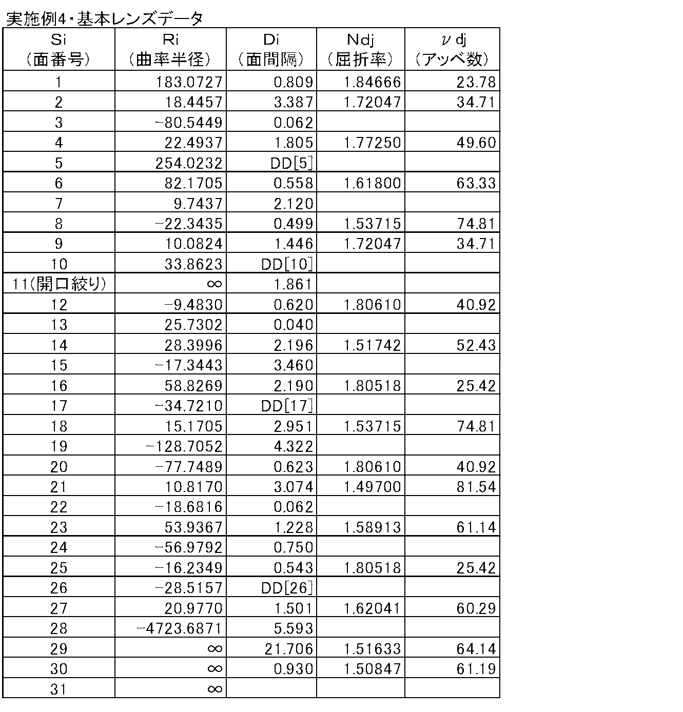

一方図8の(A)~(L)にそれぞれ、実施例4の投写用ズームレンズの各収差図を示す。

以上、実施形態および実施例を挙げて本発明を説明したが、本発明の投写用ズームレンズは、上記実施例のものに限られることなく種々の態様の変更が可能であり、例えば各レンズの曲率半径、面間隔、屈折率、アッベ数を適宜変更することが可能である。
また、本発明の投写型表示装置も前述した構成のものに限られるものではなく、例えば、用いられるライトバルブや、光束分離または光束合成に用いられる光学部材は、既述の構成に限定されず、種々の態様の変更が可能である。
Claims (17)
- 最も拡大側に配置されて変倍の際に固定されている正の屈折力を有する第1レンズ群と、
この第1レンズ群より縮小側に配置されて変倍の際に移動する少なくとも2つの移動レンズ群と、
隣り合う移動レンズ群同士の間、または1つの移動レンズ群内に配された開口絞りとを有する投写用ズームレンズにおいて、
該ズームレンズの開口数が全変倍領域において一定となるように設定され、
縮小側がテレセントリックとなるように構成されていることを特徴とする投写用ズームレンズ。 - 下記条件式(1)を満たすことを特徴とする請求項1記載の投写用ズームレンズ。
0.3<mr/fw… (1)
ただし、
mr:最も縮小側の移動レンズ群の広角端と望遠端との間の移動量
fw:広角端における全系の焦点距離 - 下記条件式(1’)を満たすことを特徴とする請求項2記載の投写用ズームレンズ。
0.5<mr/fw… (1’) - 最も縮小側に配置された最終レンズ群が、正の屈折力を有して変倍の際に固定されているものであり、
下記条件式(2)を満たすことを特徴とする請求項1または2記載の投写用ズームレンズ。
2.0<fe/fw<7.0… (2)
ただし、
fe:最終レンズ群の焦点距離
fw:広角端における全系の焦点距離 - 下記条件式(2’)を満たすことを特徴とする請求項4記載の投写用ズームレンズ。
3.0<fe/fw<5.0… (2’) - 前記第1レンズ群と、最も縮小側に配置されて変倍の際に固定されている正の屈折力を有する最終レンズ群と、前記第1レンズ群と前記最終レンズ群との間に配置されて変倍の際に移動する複数のレンズ群とから実質的に構成されており、
前記変倍の際に移動する複数のレンズ群のうち、最も拡大側のレンズ群が負の屈折力を有し、最も縮小側のレンズ群が正の屈折力を有し、
下記条件式(3)を満たすことを特徴とする請求項1または2記載の投写用ズームレンズ。
-1.0<mm/mr<-0.2… (3)
ただし、
mm:最も拡大側の移動レンズ群の広角端と望遠端との間の移動量
mr:最も縮小側の移動レンズ群の広角端と望遠端との間の移動量 - 下記条件式(3’)を満たすことを特徴とする請求項6記載の投写用ズームレンズ。
-0.7<mm/mr<-0.3… (3’) - 前記開口絞りは、変倍の全範囲に亘って開口数が一定となるように開口径を変化させることを特徴とする請求項1または2記載の投写用ズームレンズ。
- 下記条件式(4)および(5)を満たすことを特徴とする請求項1または2記載の投写用ズームレンズ。
2.0<Bf/Imφ… (4)
L/Imφ<12… (5)
ただし、
Bf:広角端における全系の縮小側のバックフォーカス(空気換算距離)
Imφ:縮小側における最大有効像円直径
L:投写距離無限遠時の最も拡大側のレンズ面から最も縮小側のレンズ面までの光軸上の距離 - 下記条件式(4’)を満たすことを特徴とする請求項9記載の投写用ズームレンズ。
2.5<Bf/Imφ… (4’) - 下記条件式(5’)を満たすことを特徴とする請求項9記載の投写用ズームレンズ。
7<L/Imφ<11… (5’) - 下記条件式(6)を満たすことを特徴とする請求項1または2記載の投写用ズームレンズ。
1.0<f1/fw<5.0… (6)
ただし、
f1:第1レンズ群の焦点距離
fw:広角端における全系の焦点距離 - 下記条件式(6’)を満たすことを特徴とする請求項12記載の投写用ズームレンズ。
2.0<f1/fw<4.0… (6’) - 拡大側から順に、前記第1レンズ群と、変倍の際に移動する負の屈折力を有する第2レンズ群と、変倍の際に移動する負の屈折力を有する第3レンズ群と、変倍の際に移動する正の屈折力を有する第4レンズ群と、変倍の際に固定されている正の屈折力を有する第5レンズ群とから実質的に構成されていることを特徴とする請求項1または2記載の投写用ズームレンズ。
- 下記条件式(7)を満たすことを特徴とする請求項1または2記載の投写用ズームレンズ。
1.4<Zr… (7)
ただし、
Zr:広角端に対する望遠端の変倍比 - 下記条件式(7’)を満たすことを特徴とする請求項15記載の投写用ズームレンズ。
1.6<Zr… (7’)
- 光源と、該光源からの光が入射するライトバルブと、該ライトバルブにより光変調された光による光学像をスクリーン上に投写する請求項1記載の投写用ズームレンズとを備えたことを特徴とする投写型表示装置。
Priority Applications (3)
| Application Number | Priority Date | Filing Date | Title |
|---|---|---|---|
| JP2014546880A JP5781704B2 (ja) | 2012-11-19 | 2013-11-15 | 投写用ズームレンズおよび投写型表示装置 |
| CN201390000895.8U CN204903852U (zh) | 2012-11-19 | 2013-11-15 | 投影用变焦透镜以及投影型显示装置 |
| US14/713,465 US9638902B2 (en) | 2012-11-19 | 2015-05-15 | Projection zoom lens and projection type display device |
Applications Claiming Priority (2)
| Application Number | Priority Date | Filing Date | Title |
|---|---|---|---|
| JP2012253318 | 2012-11-19 | ||
| JP2012-253318 | 2012-11-19 |
Related Child Applications (1)
| Application Number | Title | Priority Date | Filing Date |
|---|---|---|---|
| US14/713,465 Continuation US9638902B2 (en) | 2012-11-19 | 2015-05-15 | Projection zoom lens and projection type display device |
Publications (1)
| Publication Number | Publication Date |
|---|---|
| WO2014076961A1 true WO2014076961A1 (ja) | 2014-05-22 |
Family
ID=50730892
Family Applications (1)
| Application Number | Title | Priority Date | Filing Date |
|---|---|---|---|
| PCT/JP2013/006718 Ceased WO2014076961A1 (ja) | 2012-11-19 | 2013-11-15 | 投写用ズームレンズおよび投写型表示装置 |
Country Status (4)
| Country | Link |
|---|---|
| US (1) | US9638902B2 (ja) |
| JP (1) | JP5781704B2 (ja) |
| CN (1) | CN204903852U (ja) |
| WO (1) | WO2014076961A1 (ja) |
Cited By (1)
| Publication number | Priority date | Publication date | Assignee | Title |
|---|---|---|---|---|
| JP2021156970A (ja) * | 2020-03-25 | 2021-10-07 | パナソニックIpマネジメント株式会社 | プロジェクター |
Families Citing this family (5)
| Publication number | Priority date | Publication date | Assignee | Title |
|---|---|---|---|---|
| KR101762004B1 (ko) | 2015-07-16 | 2017-07-26 | 삼성전기주식회사 | 촬상 광학계 |
| JP6685950B2 (ja) * | 2017-02-17 | 2020-04-22 | 富士フイルム株式会社 | ズームレンズおよび撮像装置 |
| CN107632376B (zh) * | 2017-10-31 | 2024-02-23 | 舜宇光学(中山)有限公司 | 视觉镜头 |
| KR20210009720A (ko) * | 2019-07-17 | 2021-01-27 | 주식회사 레이저모션테크 | 레이저 드릴링 장치 |
| JP7344715B2 (ja) * | 2019-08-16 | 2023-09-14 | キヤノン株式会社 | ズームレンズおよび撮像装置 |
Citations (10)
| Publication number | Priority date | Publication date | Assignee | Title |
|---|---|---|---|---|
| JPH08234105A (ja) * | 1995-02-24 | 1996-09-13 | Olympus Optical Co Ltd | 望遠ズームレンズ |
| JP2003202497A (ja) * | 2002-01-04 | 2003-07-18 | Canon Inc | ズームレンズ及びそれを有する光学機器 |
| JP2003241096A (ja) * | 2002-02-18 | 2003-08-27 | Sigma Corp | ズームレンズ |
| JP2003241095A (ja) * | 2002-02-18 | 2003-08-27 | Sigma Corp | ズームレンズ |
| JP2009128683A (ja) * | 2007-11-26 | 2009-06-11 | Fujinon Corp | 投影用ズームレンズおよび投写型表示装置 |
| JP2011053295A (ja) * | 2009-08-31 | 2011-03-17 | Canon Inc | ズームレンズ及びそれを有する撮像装置 |
| JP2011107693A (ja) * | 2009-10-19 | 2011-06-02 | Canon Inc | ズームレンズ及びそれを有する撮像装置 |
| JP2012008344A (ja) * | 2010-06-24 | 2012-01-12 | Canon Inc | ズームレンズ |
| JP2013160997A (ja) * | 2012-02-07 | 2013-08-19 | Tamron Co Ltd | 大口径比内焦式望遠ズームレンズ |
| JP2014038237A (ja) * | 2012-08-17 | 2014-02-27 | Canon Inc | ズームレンズ及びそれを有する撮像装置 |
Family Cites Families (8)
| Publication number | Priority date | Publication date | Assignee | Title |
|---|---|---|---|---|
| JP2006078702A (ja) * | 2004-09-08 | 2006-03-23 | Canon Inc | ズーム光学系 |
| JP4612824B2 (ja) * | 2004-09-17 | 2011-01-12 | キヤノン株式会社 | 画像投射装置 |
| JP4871517B2 (ja) * | 2005-02-22 | 2012-02-08 | キヤノン株式会社 | ズームレンズ及びそれを有する画像投射装置 |
| JP5015739B2 (ja) * | 2007-11-26 | 2012-08-29 | 富士フイルム株式会社 | 投影用ズームレンズおよび投写型表示装置 |
| JP2010160478A (ja) * | 2008-12-08 | 2010-07-22 | Fujinon Corp | 投写用ズームレンズおよび投写型表示装置 |
| JP5512402B2 (ja) * | 2010-06-03 | 2014-06-04 | 富士フイルム株式会社 | 投写用ズームレンズおよび投写型表示装置 |
| JP5545142B2 (ja) | 2010-09-10 | 2014-07-09 | コニカミノルタ株式会社 | 変倍機能を有する投影レンズ |
| WO2013001804A1 (ja) * | 2011-06-29 | 2013-01-03 | 富士フイルム株式会社 | 投写用変倍光学系および投写型表示装置 |
-
2013
- 2013-11-15 JP JP2014546880A patent/JP5781704B2/ja not_active Expired - Fee Related
- 2013-11-15 CN CN201390000895.8U patent/CN204903852U/zh not_active Expired - Lifetime
- 2013-11-15 WO PCT/JP2013/006718 patent/WO2014076961A1/ja not_active Ceased
-
2015
- 2015-05-15 US US14/713,465 patent/US9638902B2/en active Active
Patent Citations (10)
| Publication number | Priority date | Publication date | Assignee | Title |
|---|---|---|---|---|
| JPH08234105A (ja) * | 1995-02-24 | 1996-09-13 | Olympus Optical Co Ltd | 望遠ズームレンズ |
| JP2003202497A (ja) * | 2002-01-04 | 2003-07-18 | Canon Inc | ズームレンズ及びそれを有する光学機器 |
| JP2003241096A (ja) * | 2002-02-18 | 2003-08-27 | Sigma Corp | ズームレンズ |
| JP2003241095A (ja) * | 2002-02-18 | 2003-08-27 | Sigma Corp | ズームレンズ |
| JP2009128683A (ja) * | 2007-11-26 | 2009-06-11 | Fujinon Corp | 投影用ズームレンズおよび投写型表示装置 |
| JP2011053295A (ja) * | 2009-08-31 | 2011-03-17 | Canon Inc | ズームレンズ及びそれを有する撮像装置 |
| JP2011107693A (ja) * | 2009-10-19 | 2011-06-02 | Canon Inc | ズームレンズ及びそれを有する撮像装置 |
| JP2012008344A (ja) * | 2010-06-24 | 2012-01-12 | Canon Inc | ズームレンズ |
| JP2013160997A (ja) * | 2012-02-07 | 2013-08-19 | Tamron Co Ltd | 大口径比内焦式望遠ズームレンズ |
| JP2014038237A (ja) * | 2012-08-17 | 2014-02-27 | Canon Inc | ズームレンズ及びそれを有する撮像装置 |
Cited By (2)
| Publication number | Priority date | Publication date | Assignee | Title |
|---|---|---|---|---|
| JP2021156970A (ja) * | 2020-03-25 | 2021-10-07 | パナソニックIpマネジメント株式会社 | プロジェクター |
| JP7417897B2 (ja) | 2020-03-25 | 2024-01-19 | パナソニックIpマネジメント株式会社 | プロジェクター |
Also Published As
| Publication number | Publication date |
|---|---|
| US20150247997A1 (en) | 2015-09-03 |
| JPWO2014076961A1 (ja) | 2017-01-05 |
| JP5781704B2 (ja) | 2015-09-24 |
| CN204903852U (zh) | 2015-12-23 |
| US9638902B2 (en) | 2017-05-02 |
Similar Documents
| Publication | Publication Date | Title |
|---|---|---|
| JP5766889B2 (ja) | 投写用ズームレンズおよび投写型表示装置 | |
| JP5766798B2 (ja) | 投写用変倍光学系および投写型表示装置 | |
| JP5781705B2 (ja) | 投写用ズームレンズおよび投写型表示装置 | |
| CN203930190U (zh) | 投影用变焦镜头和投影型显示设备 | |
| JP5603301B2 (ja) | 投写用変倍光学系および投写型表示装置 | |
| US9541743B2 (en) | Projection zoom lens and projection type display device | |
| CN205027961U (zh) | 投影用变焦透镜和投影型显示装置 | |
| US9557538B2 (en) | Projection zoom lens and projection type display device | |
| WO2013171995A1 (ja) | 投写用変倍光学系および投写型表示装置 | |
| WO2013061535A1 (ja) | 投写用ズームレンズおよび投写型表示装置 | |
| WO2013157237A1 (ja) | 投写用レンズおよび投写型表示装置 | |
| JP5781704B2 (ja) | 投写用ズームレンズおよび投写型表示装置 | |
| JP5777182B2 (ja) | 投写用変倍光学系および投写型表示装置 | |
| WO2012160786A1 (ja) | 投写用変倍光学系および投写型表示装置 | |
| JP5777191B2 (ja) | 投写用ズームレンズおよび投写型表示装置 | |
| JP2013007881A (ja) | 投写用変倍光学系および投写型表示装置 | |
| WO2013057910A1 (ja) | 投写用ズームレンズおよび投写型表示装置 | |
| WO2013136688A1 (ja) | 投写用ズームレンズおよび投写型表示装置 | |
| JP5611901B2 (ja) | 投写用変倍光学系および投写型表示装置 | |
| JP2014240909A (ja) | 投写用ズームレンズおよび投写型表示装置 | |
| JP2013019986A (ja) | 投写用変倍光学系および投写型表示装置 | |
| JP2013019985A (ja) | 投写用変倍光学系および投写型表示装置 |
Legal Events
| Date | Code | Title | Description |
|---|---|---|---|
| 121 | Ep: the epo has been informed by wipo that ep was designated in this application |
Ref document number: 13854358 Country of ref document: EP Kind code of ref document: A1 |
|
| ENP | Entry into the national phase |
Ref document number: 2014546880 Country of ref document: JP Kind code of ref document: A |
|
| NENP | Non-entry into the national phase |
Ref country code: DE |
|
| 122 | Ep: pct application non-entry in european phase |
Ref document number: 13854358 Country of ref document: EP Kind code of ref document: A1 |