WO2014073586A1 - タッチパネルシステム - Google Patents
タッチパネルシステム Download PDFInfo
- Publication number
- WO2014073586A1 WO2014073586A1 PCT/JP2013/080067 JP2013080067W WO2014073586A1 WO 2014073586 A1 WO2014073586 A1 WO 2014073586A1 JP 2013080067 W JP2013080067 W JP 2013080067W WO 2014073586 A1 WO2014073586 A1 WO 2014073586A1
- Authority
- WO
- WIPO (PCT)
- Prior art keywords
- detection
- indicator
- touch panel
- panel system
- capacitance
- Prior art date
- Legal status (The legal status is an assumption and is not a legal conclusion. Google has not performed a legal analysis and makes no representation as to the accuracy of the status listed.)
- Ceased
Links
Images






Classifications
-
- G—PHYSICS
- G06—COMPUTING OR CALCULATING; COUNTING
- G06F—ELECTRIC DIGITAL DATA PROCESSING
- G06F3/00—Input arrangements for transferring data to be processed into a form capable of being handled by the computer; Output arrangements for transferring data from processing unit to output unit, e.g. interface arrangements
- G06F3/01—Input arrangements or combined input and output arrangements for interaction between user and computer
- G06F3/03—Arrangements for converting the position or the displacement of a member into a coded form
- G06F3/041—Digitisers, e.g. for touch screens or touch pads, characterised by the transducing means
- G06F3/044—Digitisers, e.g. for touch screens or touch pads, characterised by the transducing means by capacitive means
- G06F3/0446—Digitisers, e.g. for touch screens or touch pads, characterised by the transducing means by capacitive means using a grid-like structure of electrodes in at least two directions, e.g. using row and column electrodes
-
- G—PHYSICS
- G06—COMPUTING OR CALCULATING; COUNTING
- G06F—ELECTRIC DIGITAL DATA PROCESSING
- G06F3/00—Input arrangements for transferring data to be processed into a form capable of being handled by the computer; Output arrangements for transferring data from processing unit to output unit, e.g. interface arrangements
- G06F3/01—Input arrangements or combined input and output arrangements for interaction between user and computer
- G06F3/03—Arrangements for converting the position or the displacement of a member into a coded form
- G06F3/041—Digitisers, e.g. for touch screens or touch pads, characterised by the transducing means
- G06F3/0412—Digitisers structurally integrated in a display
-
- G—PHYSICS
- G06—COMPUTING OR CALCULATING; COUNTING
- G06F—ELECTRIC DIGITAL DATA PROCESSING
- G06F3/00—Input arrangements for transferring data to be processed into a form capable of being handled by the computer; Output arrangements for transferring data from processing unit to output unit, e.g. interface arrangements
- G06F3/01—Input arrangements or combined input and output arrangements for interaction between user and computer
- G06F3/03—Arrangements for converting the position or the displacement of a member into a coded form
- G06F3/041—Digitisers, e.g. for touch screens or touch pads, characterised by the transducing means
- G06F3/0416—Control or interface arrangements specially adapted for digitisers
- G06F3/0418—Control or interface arrangements specially adapted for digitisers for error correction or compensation, e.g. based on parallax, calibration or alignment
-
- G—PHYSICS
- G09—EDUCATION; CRYPTOGRAPHY; DISPLAY; ADVERTISING; SEALS
- G09G—ARRANGEMENTS OR CIRCUITS FOR CONTROL OF INDICATING DEVICES USING STATIC MEANS TO PRESENT VARIABLE INFORMATION
- G09G3/00—Control arrangements or circuits, of interest only in connection with visual indicators other than cathode-ray tubes
- G09G3/20—Control arrangements or circuits, of interest only in connection with visual indicators other than cathode-ray tubes for presentation of an assembly of a number of characters, e.g. a page, by composing the assembly by combination of individual elements arranged in a matrix no fixed position being assigned to or needed to be assigned to the individual characters or partial characters
- G09G3/34—Control arrangements or circuits, of interest only in connection with visual indicators other than cathode-ray tubes for presentation of an assembly of a number of characters, e.g. a page, by composing the assembly by combination of individual elements arranged in a matrix no fixed position being assigned to or needed to be assigned to the individual characters or partial characters by control of light from an independent source
- G09G3/36—Control arrangements or circuits, of interest only in connection with visual indicators other than cathode-ray tubes for presentation of an assembly of a number of characters, e.g. a page, by composing the assembly by combination of individual elements arranged in a matrix no fixed position being assigned to or needed to be assigned to the individual characters or partial characters by control of light from an independent source using liquid crystals
- G09G3/3611—Control of matrices with row and column drivers
-
- G—PHYSICS
- G06—COMPUTING OR CALCULATING; COUNTING
- G06F—ELECTRIC DIGITAL DATA PROCESSING
- G06F2203/00—Indexing scheme relating to G06F3/00 - G06F3/048
- G06F2203/041—Indexing scheme relating to G06F3/041 - G06F3/045
- G06F2203/04103—Manufacturing, i.e. details related to manufacturing processes specially suited for touch sensitive devices
-
- G—PHYSICS
- G06—COMPUTING OR CALCULATING; COUNTING
- G06F—ELECTRIC DIGITAL DATA PROCESSING
- G06F2203/00—Indexing scheme relating to G06F3/00 - G06F3/048
- G06F2203/041—Indexing scheme relating to G06F3/041 - G06F3/045
- G06F2203/04106—Multi-sensing digitiser, i.e. digitiser using at least two different sensing technologies simultaneously or alternatively, e.g. for detecting pen and finger, for saving power or for improving position detection
-
- G—PHYSICS
- G09—EDUCATION; CRYPTOGRAPHY; DISPLAY; ADVERTISING; SEALS
- G09G—ARRANGEMENTS OR CIRCUITS FOR CONTROL OF INDICATING DEVICES USING STATIC MEANS TO PRESENT VARIABLE INFORMATION
- G09G2310/00—Command of the display device
- G09G2310/02—Addressing, scanning or driving the display screen or processing steps related thereto
- G09G2310/0202—Addressing of scan or signal lines
-
- G—PHYSICS
- G09—EDUCATION; CRYPTOGRAPHY; DISPLAY; ADVERTISING; SEALS
- G09G—ARRANGEMENTS OR CIRCUITS FOR CONTROL OF INDICATING DEVICES USING STATIC MEANS TO PRESENT VARIABLE INFORMATION
- G09G2310/00—Command of the display device
- G09G2310/02—Addressing, scanning or driving the display screen or processing steps related thereto
- G09G2310/0264—Details of driving circuits
- G09G2310/027—Details of drivers for data electrodes, the drivers handling digital grey scale data, e.g. use of D/A converters
-
- G—PHYSICS
- G09—EDUCATION; CRYPTOGRAPHY; DISPLAY; ADVERTISING; SEALS
- G09G—ARRANGEMENTS OR CIRCUITS FOR CONTROL OF INDICATING DEVICES USING STATIC MEANS TO PRESENT VARIABLE INFORMATION
- G09G2354/00—Aspects of interface with display user
Definitions
- the present invention relates to a touch panel system and an electronic information device including the touch panel system.
- touch panel systems that accept user instructions by detecting the position of an indicator (for example, a user's finger or stylus, the same applies hereinafter) that is in contact with or close to the detection surface of the touch panel have become portable phones, personal computers, It is becoming more and more mounted on such as.
- an indicator for example, a user's finger or stylus, the same applies hereinafter
- a projected capacitive touch panel system capable of multi-touch operation (simultaneously detecting a plurality of indicators that are in contact with or close to the detection surface of the touch panel) has become a resistive touch panel system. Instead, it has become widely used.
- a plurality of upper electrodes provided so as to be parallel to each other along the detection surface and provided so as to be parallel to each other along the detection surface so as to intersect the upper electrode
- a touch panel provided with a lower electrode is used.
- the upper electrode is provided between the lower electrode and the detection surface, and the upper electrode and the lower electrode have a two-layer structure.
- Projected capacitive touch panel systems include self-capacitance and mutual capacitance.
- the self-capacitance method signals are obtained from the upper electrode and the lower electrode, and the change (increase) in the capacitance of the upper electrode and the lower electrode is detected.
- the position and the position of the indicator in the alignment direction of the lower electrode are separately detected.
- the mutual capacitance method drives one electrode (hereinafter, illustrated for the case of the lower electrode) and obtains a signal from the other electrode (hereinafter, illustrated for the case of the upper electrode)
- the position of the indicator in the detection surface is detected by detecting a change (decrease) in capacitance between the electrode and the lower electrode.
- the distance between the detection surface and the lower electrode is larger than the distance between the detection surface and the upper electrode. Therefore, in the self-capacitance type touch panel system, the change amount (increase amount) of the capacitance of the lower electrode when the indicator contacts or approaches the detection surface is changed by the change amount (increase amount) of the upper electrode capacitance. ) Smaller than Therefore, the detection accuracy of the position of the indicator based on the output signal of the lower electrode is lower than the detection accuracy of the position of the indicator based on the output signal of the upper electrode.
- Patent Document 1 in the self-capacitance type touch panel system, by making the area of the lower electrode larger than the area of the upper electrode, the capacitance of the lower electrode when the indicator is in contact with or close to the detection surface.
- a touch panel system with a large amount of change (increase) has been proposed.
- a plurality of upper electrodes and lower electrodes are arranged side by side. Therefore, a parasitic capacitance is formed between the indicator and the plurality of detection electrodes (the upper electrode and the lower electrode in the self-capacitance method, and the upper electrode in the mutual capacitance method), thereby the plurality of detection electrodes. A change in capacitance is detected from each output signal.
- the centroid position is indicated in the detection plane. It is conceivable to employ a method for detecting the position of the body. However, the amount of change in capacitance at the center of gravity position varies greatly depending on the actual position of the indicator (whether or not it exists on the center line of the detection electrode).
- the indicator exists at a position away from the center line of a certain detection electrode, not only the detection point and the detection electrode but also the periphery of the indicator and the detection electrode is detected. A parasitic capacitance is also formed between the electrodes for use. Therefore, the amount of change in capacitance at the position of the center of gravity is smaller than that in the above case. Therefore, in this case, it is difficult to detect the indicator.
- one or both of a position where the indicator is not easily detected and a position where the indicator is easily detected are generated in the detection surface.
- the detection accuracy of the indicator decreases.
- the upper electrode is sufficiently separated in order to reduce the influence of parasitic capacitance formed between adjacent detection electrodes.
- the greater the distance between the upper electrodes the smaller the amount of change in capacitance when there is an indicator between the upper electrodes, so the detection accuracy of the indicator decreases.
- an object of the present invention is to provide a touch panel system with improved indicator detection accuracy and an electronic information device including the touch panel system.
- the present invention is based on a touch panel having a plurality of electrodes, and an output signal indicating the capacitance formed by at least a part of the electrodes and contacting the detection surface.
- an indicator position detection unit that detects the position of an adjacent indicator, and the indicator position detection unit has a detection sensitivity for each predetermined position in the detection surface so as to correspond to the pattern of the electrodes.
- a touch panel system is provided that corrects and detects the position of the indicator within the detection surface.
- correcting the detection sensitivity means changing the relative relationship between the detection criterion and a signal value (for example, a capacitance change amount or capacitance value described later) to which the detection criterion is applied. It is to let you. Specifically, for example, one or both of changing the detection reference and changing the signal value are included in the correction of the detection sensitivity.
- the position of the indicator in the detection surface is detected using a detection reference set for each predetermined position in the detection surface P so as to correspond to the pattern of the electrodes. May be.
- the indicator position detection unit is based on a capacitance value corresponding to a capacitance at each predetermined position in the detection surface, which is obtained by processing the output signal.
- the indicator position detection unit detects the position of the indicator in the detection surface, and the indicator position detector is a correction set for each predetermined position in the detection surface so as to correspond to the pattern of the electrodes.
- the capacitance value may be corrected by a method, and the position of the indicator in the detection surface may be detected based on the obtained corrected capacitance value.
- the indicator position detection unit includes the capacitance value corresponding to a certain position in the detection surface and the electrostatic capacity corresponding to at least one position around the certain position.
- the capacitance value corresponding to the certain position may be corrected based on the capacitance value.
- the indicator position detection unit corrects the detection reference by a correction method set for each predetermined position in the detection surface so as to correspond to the pattern of the electrodes, and after correction The position of the indicator in the detection surface may be detected using the detection criterion.
- the touch panel intersects with the lower electrode between the detection surface and the lower electrode, and a plurality of lower electrodes provided parallel to each other along the detection surface as the electrode. And a plurality of upper electrodes provided in parallel to each other along the detection surface, and the indicator is more easily detected in a position away from the center line of the upper electrode in the detection surface. It is preferable that the detection sensitivity is corrected.
- the indicator position detection unit includes the capacitance obtained from the output signal obtained in a state where the indicator that is in contact with or close to the detection surface does not exist, and the detection By comparing the capacitance obtained from the output signal obtained at the time of detecting the position of the indicator in a plane, the distribution of the variation in the capacitance is obtained, and the variation in the capacitance If the amount of change in the capacitance at the center of gravity of the distribution is larger than the detection reference, the center of gravity is detected as the position of the indicator in the detection surface. It is preferable that the smaller the detection reference is set, the further away from the center line of the upper electrode.
- the detection sensitivity correction method may be set based on a processing result of the output signal obtained when the indicator actually contacts the detection surface.
- the display device further includes a display device that displays an image, and a host terminal that controls the image displayed by the display device, and the display device displays the image of the display device on the display surface.
- a touch panel is provided, and the host terminal controls the image displayed by the display device to guide the indicator to contact a predetermined position in the detection surface, and the output signal obtained thereby Based on the above, a method for correcting the detection sensitivity may be obtained.
- the detection sensitivity correction method may be set based on the characteristics of the electrode pattern.
- a detection sensitivity correction method setting unit that performs at least one of setting and updating of the detection sensitivity correction method based on the processing result of the output signal by the indicator position detection unit. , May be further provided.
- the electrode may be formed of a pattern in which a plurality of polygonal or circular pad portions are linearly connected.
- the touch panel system having the above characteristics may further include a display device that displays an image, and the touch panel may be provided on a display surface on which the image of the display device is displayed.
- the display device may be a liquid crystal display, a plasma display, an organic EL display, or a field emission display.
- the present invention also provides an electronic information device comprising the touch panel system having the above characteristics.
- the touch panel system and the electronic information device having the above characteristics, it is possible to detect an indicator that is in contact with or close to the detection surface at an appropriate detection sensitivity according to the position at any position in the detection surface. . Therefore, the detection accuracy of the indicator can be improved.
- 1 is a block diagram showing a configuration example of an electronic information device according to a first embodiment of the present invention.
- movement of the indicator position detection part shown in FIG. The figure shown about each example of the correction method of the pattern of an electrode, and an electrostatic capacitance value.
- movement of the indicator position detection part shown in FIG. The figure shown about each example of the correction method of the pattern of an electrode, and a detection reference
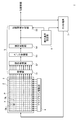
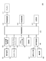
- FIG. 1 is a block diagram showing an overall configuration example of a touch panel system according to the first embodiment of the present invention.
- the touch panel system 1 includes a display device 2 that displays an image on a display surface, and a touch screen system 1 that is provided on the display surface of the display device 2 and touches the detection surface P by driving a drive line DL.
- a touch panel 3 that outputs an output signal according to the presence or absence of an adjacent indicator from the sense line SL, a drive line drive unit 4 that drives the drive line DL, and an output signal that is output from the sense line SL to detect the detection surface
- An indicator position detection unit 5 that detects the position of the indicator in P, and a detection reference setting unit 6 that sets a detection reference used when the indicator position detection unit 5 detects the position of the indicator in the detection surface P. (Detection sensitivity correction method setting unit) and a host terminal 7 that controls an image displayed on the display device 2.
- the display device 2 includes, for example, a liquid crystal display, a plasma display, an organic EL display, a field emission display, and the like.
- the display apparatus 2 is not restricted to these, What kind of thing may be sufficient.
- the touch panel 3 is provided in parallel with each other along the detection surface P, and is driven by giving a predetermined drive signal to each of them, and intersects the drive lines DL (three-dimensional intersection).
- a plurality of sense lines that are provided parallel to each other along the detection surface P and that output an output signal corresponding to the capacitance formed between the drive line DL and the drive line DL are driven.
- SL upper electrode
- the sense line SL is provided between the drive line DL and the detection surface P.
- the output signal indicates whether the indicator is in contact with or close to the detection region X in the detection surface P (the intersection of the drive line DL and the sense line SL and the vicinity thereof, and the same applies hereinafter).
- FIG. 1 illustrates the case where the drive line DL and the sense line SL intersect perpendicularly, they may intersect at an angle other than perpendicular.
- the drive line driving unit 4 is driven by applying a predetermined signal to the drive line DL.
- the sense line SL that intersects the driven drive line DL outputs an output signal corresponding to the capacitance formed between the drive line DL and the drive line DL.
- one sense line SL outputs an output signal corresponding to a plurality of capacitances formed between the plurality of drive lines DL.
- the indicator position detection unit 5 obtains each capacitance from the output signal corresponding to such a superimposed capacitance by a decoding process of the decoding processing unit 54 described later. Is possible.
- the indicator position detection unit 5 includes an amplification unit 51 that amplifies an output signal output from the sense line SL, a signal acquisition unit 52 that acquires the output signal amplified by the amplification unit 51 and outputs the output signal in a time division manner, and a signal acquisition unit An A / D converter 53 that converts the analog signal output from 52 into a digital signal, and a decoding that obtains the distribution of the amount of change in capacitance in the detection plane P based on the digital signal converted by the A / D converter 53 Based on the distribution of the amount of change in capacitance obtained by the processing unit 54 and the decoding processing unit 54, the position information generating unit 55 detects the position of the indicator in the detection surface P and generates position information indicating the position. And comprising.
- the decoding processing unit 54 decodes the digital signal obtained from the A / D conversion unit 53 based on the signal pattern of the drive signal given to the drive line DL by the drive line driving unit 4, so that the detection signal within the detection plane P is obtained. Obtain the capacitance distribution (two-dimensional distribution). Further, the decoding processing unit 54 is obtained in a state where there is no indicator that is in contact with or close to the detection surface P before the detection of the indicator (for example, during calibration performed immediately after the touch panel system is activated). By obtaining a digital signal obtained from the output signal, a capacitance distribution (two-dimensional distribution) in the detection surface P in a state where there is no indicator in contact with or close to the detection surface P is obtained in advance. ing.
- the decoding processing unit 54 detects the electrostatic capacitance distribution in the detection surface P in a state where there is no indicator that is in contact with or close to the detection surface P, and the static in the detection surface P obtained when detecting the position of the indicator. And the distribution of the capacitance change amount in the detection surface P (that is, the capacitance component changed due to contact or proximity of the indicator to the detection surface P). 2D distribution).
- the amount of change in capacitance at each predetermined position in the detection surface P is expressed as “capacitance value” for convenience of explanation.
- the decoding processing unit 54 detects the detection surface P obtained at the time of detecting the position of the indicator from the distribution of capacitance in the detection surface P in a state where there is no indicator that is in contact with or close to the detection surface P. By subtracting the electrostatic capacity distribution in the inner surface, the distribution of the change amount of the electrostatic capacity in the detection surface P is obtained. Note that the amount of change in capacitance may be an absolute value.
- the position information generation unit 55 is set for each distribution of capacitance variation in the detection plane P obtained by the decoding processing unit 54 and for each predetermined position in the detection plane P (for example, the sense line SL and the sense line SL).
- the position of the indicator in the detection surface P is obtained by using a detection reference (which is two-dimensionally set at an interval shorter than the interval between the intersections of the drive lines DL), and position information is generated.
- the position information generation unit 55 obtains the center of gravity position of the distribution of the change amount of the capacitance in the detection surface P, and if the change amount of the capacitance at the center of gravity position is larger than the detection reference, The position of the center of gravity is the position of the indicator that is in contact with or close to the detection surface P.
- the position information generation unit 55 may obtain the center-of-gravity position using all the amount of change in capacitance within the detection surface P, or a part (for example, the amount of change in capacitance is greater than a predetermined threshold value).
- the position of the center of gravity may be obtained using a portion that also increases.
- the position information generation unit 55 performs an interpolation process or the like on the amount of change in capacitance in the detection region X in the vicinity of the center of gravity position (or all in the detection surface P), thereby performing static processing at the center of gravity position.
- the amount of change in capacitance may be obtained.
- the position information generation unit 55 generates and outputs position information indicating the position of the indicator in the detection surface P. If the position information generating unit 55 cannot determine the position of the indicator that is in contact with or close to the detection surface P, such as when there is no indicator that is in contact with or close to the detection surface P, the position information generation unit 55 Position information indicating that may be generated and output. Details of the detection criterion will be described later.
- the detection standard setting unit 6 sets a detection standard used by the position information generation unit 55 based on the distribution of the change amount of the capacitance obtained from the decoding processing unit 54.
- the position information generation unit 55 stores the detection reference obtained by the detection reference setting unit 6. Details of the operation of the detection reference setting unit 6 will be described later with a specific operation example.
- the host terminal 7 controls the entire touch panel system 1, and in particular controls an image displayed on the display device 2. Although not particularly illustrated in FIG. 1, the host terminal 7 can control the drive line driving unit 4, each part of the indicator position detection unit 5, and the like. Details of the operation of the host terminal 7 will be described later with a specific operation example.
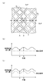
- FIG. 2 is a diagram showing specific examples of electrode patterns and detection reference setting methods.
- FIG. 2A is a plan view showing a specific example of an electrode pattern.
- FIG. 2B is a graph that displays the change amount of the capacitance and the detection reference together when a detection reference having a constant value is set.
- FIG. 2C is a graph that displays the change in capacitance and the detection reference together when the detection reference corresponding to the sense line pattern is set.
- the positions on the horizontal axis of the graphs shown in FIGS. 2B and 2C correspond to the positions of the thick broken lines shown in FIG.
- the amount of change in capacitance shown in FIGS. 2B and 2C is the amount of change in each position when the indicator is brought into contact with each position on the thick broken line in FIG. It shows the amount of change in capacitance.
- the drive line DL includes a drive line pad portion DLP having a locally increased area except for a portion intersecting the sense line SL.
- the sense line SL includes a sense line pad portion SLP having a locally increased area except for a portion intersecting the drive line DL.
- a capacitance C is formed between the SLP and the SLP.
- the drive line DL may not include the drive line pad portion DLP, and the sense line SL may not include the sense line pad portion SLP. Even in this case, the capacitance C is formed at the intersection of the drive line DL and the sense line SL.
- the amount of change in capacitance varies greatly depending on the position of the indicator within the detection surface P. Specifically, when the indicator exists at the position B on the center line of the sense line SL, the amount of change in capacitance increases. On the other hand, when the indicator is present at a position A away from the center line of the sense line SL, the amount of change in capacitance is small.
- a detection standard corresponding to the pattern (for example, size, shape, arrangement interval, arrangement position, etc.) of the sense line SL is set.
- a detection reference that is larger as it is closer to the center line of the sense line SL and smaller as it is farther from the center line of the sense line SL is set.
- the detection sensitivity is corrected so as to correspond to the pattern of the sense line SL for each predetermined position in the detection surface P.
- the detection sensitivity is a relative relationship between the amount of change in capacitance and the detection reference, the detection sensitivity can be corrected by changing either (or both).
- the detection sensitivity is corrected by setting a changed detection reference.
- the touch panel system 1 at any position within the detection surface P, using an appropriate detection reference (that is, appropriate detection sensitivity) according to the position, It is possible to detect an indicator that is in contact with or close to the detection surface P. Therefore, the detection accuracy of the indicator can be improved.
- an appropriate detection reference that is, appropriate detection sensitivity
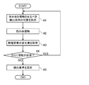
- FIG. 3 is a flowchart illustrating a specific operation example of the touch panel system for setting the detection reference. Note that the operation of the flowchart shown in FIG. 3 is performed mainly when the touch panel system 1 is activated or when the user instructs resetting of the detection criteria.
- the detection reference setting unit 6 instructs the host terminal 7 on the detection surface P where the indicator should be brought into contact.
- the host terminal 7 controls the image displayed on the display device 2 to instruct the user on the position where the indicator should be brought into contact (step # 1).
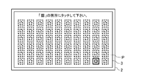
- FIG. 4 is a diagram illustrating a specific example of an image displayed on the display surface of the display device when setting the detection reference.
- FIG. 4 shows a case where an image in which a plurality of double rings (graphics similar to “Kanji”) are arranged on the display surface of the display device 2 is displayed.
- the host terminal 7 displays only the double ring of the position in the detection surface P where the indicator should be contacted by a solid line and the other is indicated by a broken line, thereby clearly indicating the position where the indicator should be contacted to the user. Directly. Then, the user who sees this image is guided to bring a pointer such as a finger into contact with the display position of the double ring displayed with a solid line.
- the detection reference setting unit 6 determines the amount of change in capacitance output from the decoding processing unit 54. From the distribution, the amount of change in capacitance at the position is acquired (step # 3). Then, the detection reference setting unit 6 confirms whether or not further contact of the indicator with the detection surface P is necessary (for example, whether or not all planned contacts of the indicator have been completed) (step #). 4).
- the detection reference setting unit 6 makes the indicator contact with the host terminal 7 within the detection surface P (particularly, Then, a position different from the position designated last time is designated again (step # 1).
- the detection reference setting unit 6 determines the capacitance at each position in the detection surface P acquired in step # 3. Based on the amount of change, the detection reference for each position is set (step # 5), and the operation ends.
- FIG. 4 although illustrated about the case where the image on which the figure was arranged was displayed on the display surface of the display apparatus 2, you may display images other than a figure.
- an image in which a plurality of input button images indicating different characters (including numbers and symbols) are arranged may be displayed.
- the host terminal 7 indicates an input button image at a position where the indicator in the detection surface P should be brought into contact with, for example, a predetermined character constituting a character string such as a password recognized by the user, The position where the indicator should be brought into contact may be implicitly indicated to the user.
- the user who sees the image is guided to bring a pointer such as a finger into contact with the display position of the input button image indicating the predetermined character.
- the number of contact of the indicator with the detection surface P (the number of repetitions of steps # 1 and # 2) too much.
- the number of times of contact of the indicator with the detection surface P is reduced, the number of changes in the capacitance when the indicator contacts the detection surface P that can be acquired by the detection reference setting unit 6 is reduced. .
- the detection standard setting unit 6 may generate data necessary for setting the detection standard by performing interpolation processing or the like as necessary. Specifically, for example, the detection reference setting unit 6 adds and averages the detection references obtained for a plurality of positions (for example, position A and position B in FIG. 2) set by the above-described operation, thereby A detection criterion may be obtained. Further, the detection reference setting unit 6 averages the detection references obtained for the positions (for example, a plurality of positions on the center line of the sense lines SL) where the relative positional relationship with the pattern of the sense lines SL is the same. Detection criteria at other similar positions may be set. Further, the detection reference setting unit 6 may perform these calculations on the change amount of the capacitance obtained in step # 3.
- the detection reference setting unit 6 adds and averages the detection references obtained for a plurality of positions (for example, position A and position B in FIG. 2) set by the above-described operation, thereby A detection criterion may be obtained. Further, the detection reference setting unit 6 averages the
- FIG. 5 is a block diagram illustrating a configuration example of the electronic information device according to the first embodiment of the present invention.
- the electronic information device 100 includes a display device 101 (corresponding to the display device 2 of FIG. 1), a display device control unit 102 that controls the display device 101,
- a display device control unit 102 that controls the display device 101
- the touch panel 103 corresponding to the touch panel 3 in FIG. 1
- the touch panel controller 104 corresponding to the drive line driving unit 4, the indicator position detecting unit 5 and the detection reference setting unit 6 in FIG. 1 are pressed by the user.
- a button switch unit 105 that accepts user instructions, an imaging unit 106 that generates image data by imaging, an audio output unit 107 that outputs input audio data as audio, and a sound collection unit that generates audio data by collecting sound 108, an audio processing unit 109 that performs processing of audio data given to the audio output unit 107 and processing of audio data given from the sound collection unit 108, and electronic information Wireless communication unit 110 that wirelessly communicates communication data with devices external to device 100, and communication data that wireless communication unit 110 communicates wirelessly as electromagnetic waves and electromagnetic waves emitted from devices external to electronic information device 100
- An antenna 111 that receives the data, a wired communication unit 112 that communicates communication data with devices external to the electronic information device 100 by wire, a storage unit 113 that stores various data, and the overall operation of the electronic information device 100.
- a main body control unit 114 (corresponding to the host terminal 7).
- the indicator position detection unit 5 and the detection reference setting unit 6 described above may be part of the main body control unit 114 instead of the touch panel controller 104.
- the electronic information device 100 illustrated in FIG. 5 is only one application example of the touch panel system 1.
- the touch panel system 1 described above can be applied to an electronic information device having a configuration different from that of the electronic information device 100.
- the present invention can also be applied to other touch panel systems. Specifically, for example, the present invention can be applied to a self-capacitance type touch panel system. As described above, in the self-capacitance type touch panel system, the position of the indicator in the alignment direction of the upper electrode and the position of the indicator in the alignment direction of the lower electrode are detected separately. Therefore, the present invention is applicable to one or both of these two types of position detection.
- the drive line DL and the sense line SL may be made of a transparent material such as ITO (IndiumInTin Oxide), or may be made of other materials. Good.
- the drive line DL and the sense line SL may be configured with a mesh of fine metal wires F.
- FIG. 6 is a plan view showing another example of the electrode structure.
- a drive line DL which is a pattern in which a plurality of rhombus drive line pad portions DLP are linearly connected, and a plurality of rhombus sense line pad portions SLP are linearly connected.
- the touch panel 3 including the sense line SL as a pattern is illustrated, the patterns of the dry line DL and the sense line SL are not limited to these examples.
- the drive line DL and the sense line SL may be a pattern in which a plurality of circular pad portions are linearly connected, or a pattern in which a plurality of polygonal pad portions such as squares and hexagons are linearly connected. Also good.
- the pattern of the sense line SL is not necessarily the same shape as the pattern of the drive line DL, and may be a shape different from the pattern of the drive line DL.
- FIG. 5 illustrates the operation when the detection reference is set using the change amount of the capacitance obtained when the indicator is brought into contact with the detection surface P by the user, It is also possible to set the detection standard according to the operation or the method.
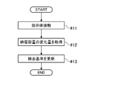
- FIG. 7 is a flowchart illustrating a specific operation example of the touch panel system for updating the detection reference. Note that the operation shown in FIG. 7 is performed when the update is performed once, and the operation can be repeatedly performed.
- the indicator touches the detection surface P (step # 11)
- the detection reference setting unit 6 detects the position where the indicator contacts in the detection P from the distribution of the change amount of the capacitance output from the decoding processing unit 54, and the capacitance at the position. Is obtained (step # 12).
- the detection reference setting unit 6 updates the detection reference based on the change amount of the capacitance acquired in step # 12 (step # 13).
- the detection reference setting unit 6 may update the detection reference only at the position where the indicator contacts in the detection surface P using the change amount of the capacitance obtained in step # 12, or interpolation. Processing or the like may be performed to update the detection criteria for other positions.
- the initial state of the detection reference may be a constant value as shown in FIG. 2B, or as shown in FIG. It may be set corresponding to the pattern of the sense line SL.
- the detection criterion update according to the method of this example may be performed constantly, but may be performed when a user instructs, or may be performed automatically every predetermined period. .
- the detection reference corresponds to the pattern of the sense line SL. Therefore, for example, before shipping the touch panel system 1 (or the electronic information device 100), the detection reference is obtained from the pattern characteristics of the sense line SL without actually bringing the indicator into contact with or close to the detection surface P. It is also possible to set. An example of a method for setting the detection reference in this way will be described with reference to the drawings.
- FIG. 8 is a flowchart illustrating an example of a detection reference setting method.
- the pattern features of the sense line SL are extracted (step # 21). Specifically, for example, the size and shape of the sense line SL, the arrangement interval, the arrangement position, and the like are extracted as features.
- the indicator comes into contact with each position on the detection surface P as shown in FIGS. 2 (b) and 2 (c).
- the amount of change in capacitance at each position in the case is estimated by simulation or the like (step # 22).
- a detection reference for each position is set by the same method as in step # 5 in FIG. 3 (step #). 23).
- a detection reference may be obtained using an arithmetic device outside the touch panel system 1 and the detection reference may be stored in the position information generation unit 55.
- the detection reference setting unit 6 may not be provided in the touch panel system 1.
- the detection reference setting method of this example is combined with another detection reference setting method (specifically, for example, the above [3 ], The detection criterion setting unit 6 may need to be provided in the touch panel system 1.
- FIG. 2 the case where the detection reference is mainly set according to the pattern of the sense line SL that is the upper electrode is illustrated, but the relative position between the contact position of the indicator and the pattern of the drive line DL that is the drive electrode If there is a relationship between the general positional relationship and the amount of change in capacitance, a detection reference corresponding to the pattern of the drive line DL as well as the pattern of the sense line SL may be set.
- the indicator Before the touch panel system 1 (or the electronic information device 100) is shipped, the indicator contacts the detection surface P by processing an output signal obtained by bringing the indicator into contact with various positions in the detection surface P.
- a detection reference corresponding to the pattern of the sense line SL may be set by using a test device that obtains the amount of change in capacitance at that time. In this case, the touch panel system 1 may not include the detection reference setting unit 6.
- touch panel systems according to second and third embodiments of the present invention will be described with reference to the drawings.
- the touch panel system according to the second and third embodiments of the present invention will be described focusing on differences from the touch panel system 1 according to the first embodiment described above (see FIGS. 1 to 8). The description of the same points will be omitted as appropriate.
- the description of the touch panel system 1 according to the first embodiment described above is naturally applicable to the touch panel system 1 according to the second and third embodiments of the present invention as long as there is no particular contradiction.
- the touch panel system according to the second and third embodiments described below is similar to the touch panel system 1 according to the first embodiment described above with respect to the electronic information device 100 according to the first embodiment (see FIG. 5). It is applicable.
- FIG. 9 is a block diagram showing an overall configuration example of the touch panel system according to the second embodiment of the present invention.
- the touch panel system 1A according to the second embodiment of the present invention includes a display device 2, a touch panel 3, a pointer position detection unit 5A, a correction method setting unit 6A, a host terminal 7, Is provided. That is, the touch panel system 1A according to the second embodiment of the present invention includes a pointer position detection unit 5A different from the pointer position detection unit 5 included in the touch panel system 1 according to the first embodiment described above, and a detection criterion. It differs from the touch panel system 1 according to the first embodiment described above in that a correction method setting unit 6A (detection sensitivity correction method setting unit) is provided instead of the setting unit 6.
- a correction method setting unit 6A detection sensitivity correction method setting unit
- the indicator position detection unit 5A includes a correction unit 56 in addition to the amplification unit 51, the signal acquisition unit 52, the A / D conversion unit 53, the decoding processing unit 54, and the position information generation unit 55.
- the correction unit 56 corrects the capacitance value output from the decoding processing unit 54 and inputs the corrected capacitance value to the position information generation unit 55. Further, the correction method of the capacitance value in the correction unit 56 is set by the correction method setting unit 6A.
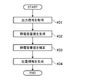
- FIG. 10 is a flowchart showing an example of the operation of the indicator position detection unit shown in FIG.
- the indicator position detection unit 5A first acquires an output signal from the sense line SL (step # 31). Next, the indicator position detection unit 5A generates a capacitance value via the amplification unit 51, the signal acquisition unit 52, the A / D conversion unit 53, and the decoding processing unit 54 (step # 32). The operation so far is the same as that of the indicator position detection unit 5 provided in the touch panel system 1 according to the first embodiment described above.
- the correction unit 56 corrects the capacitance value generated in step # 32 by the correction method set by the correction method setting unit 6A (step # 33).
- the position information generation unit 55 detects the position of the indicator in the detection surface P based on the capacitance value corrected in step # 33, and generates position information (step # 34). .
- FIG. 11 is a diagram illustrating specific examples of the electrode pattern and the capacitance value correction method.
- Fig.11 (a) is a top view shown about the specific example of the pattern of an electrode.
- FIG. 11B is a graph displaying both the capacitance value and the detection reference when the capacitance value is not corrected.
- FIG. 11C is a graph displaying both the capacitance value and the detection reference when the capacitance value is corrected.
- FIG. 11A shows the same electrode pattern as in FIG.
- FIG.11 (b) and FIG.11 (c) are the graphs displayed by the method similar to FIG.2 (b) and FIG.2 (c), and the position A and the position B shown in FIG. Capacitance values and detection criteria for each are shown.
- the positions A and B in FIGS. 11A to 11C are the same positions as the positions A and B shown in FIGS. 2A to 2C.
- the indicator is in contact with each of the position A and the position B.
- the correction method setting unit 6A sets a capacitance value correction coefficient for each predetermined position in the detection surface P. Then, the correction unit 56 corrects the capacitance value by multiplying the capacitance value at each predetermined position in the detection surface P by the corresponding capacitance value correction coefficient. Specifically, in this example, a capacitance value correction coefficient of “1.6” is set for the position A and “1.3” is set for the position B.
- the capacitance value after correction is corrected at both the position A and the position B by correcting the capacitance value at each position. Can exceed the detection criteria, respectively.
- the touch panel system 1A according to the second embodiment of the present invention also corrects the detection sensitivity similarly to the touch panel system 1 according to the first embodiment described above. However, in the touch panel system 1A according to the second embodiment, the detection sensitivity is corrected by correcting and changing the capacitance value.
- the capacitance value is corrected by an appropriate correction method according to the position at any position in the detection surface P (that is, As an appropriate detection sensitivity, it is possible to detect an indicator that is in contact with or close to the detection surface P. Therefore, the detection accuracy of the indicator can be improved.
- the detection reference setting method in the touch panel system 1 according to the first embodiment described above (FIG. 3 to FIG. 3). 5)) and the same method can be adopted.
- the correction unit 56 corrects the capacitance value
- the surrounding capacitance value may be used.
- the correction unit 56 is based on the capacitance value corresponding to a certain position in the detection surface P and the capacitance value corresponding to at least one position around the certain position. You may correct
- the capacitance value can be corrected in consideration of the state of the surrounding capacitance value. Therefore, it is possible to further improve the detection accuracy of the indicator.
- the touch panel system 1A according to the second embodiment of the present invention is not contrary to the touch panel system 1 according to the first embodiment described above, and can be implemented in combination. That is, it is good also as a touch panel system provided with both the detection reference setting part 6, the correction
- FIG. 12 is a block diagram showing an overall configuration example of a touch panel system according to the third embodiment of the present invention.
- a touch panel system 1B according to a third embodiment of the present invention includes a display device 2, a touch panel 3, a pointer position detection unit 5B, a correction method setting unit 6B, a host terminal 7, Is provided. That is, the touch panel system 1B according to the third embodiment of the present invention includes a pointer position detection unit 5B different from the pointer position detection unit 5 included in the touch panel system 1 according to the first embodiment described above, and a detection criterion. It differs from the touch panel system 1 according to the first embodiment described above in that a correction method setting unit 6B (detection sensitivity correction method setting unit) is provided instead of the setting unit 6.
- a correction method setting unit 6B detection sensitivity correction method setting unit
- the pointer position detection unit 5B includes an amplification unit 51, a signal acquisition unit 52, an A / D conversion unit 53, a decoding processing unit 54, and position information. And a generation unit 55B.
- the position information generation unit 55B detects the position of the indicator within the detection surface P using the detection reference corrected by the correction method set by the correction method setting unit 6B.
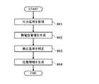
- FIG. 13 is a flowchart showing an example of the operation of the indicator position detection unit shown in FIG.
- the indicator position detection unit 5B first acquires an output signal from the sense line SL (step # 41). Next, the pointer position detection unit 5 generates a capacitance value via the amplification unit 51, the signal acquisition unit 52, the A / D conversion unit 53, and the decoding processing unit 54 (step # 42). The operation so far is the same as that of the indicator position detection unit 5 provided in the touch panel system 1 according to the first embodiment described above.
- the position information generation unit 55B corrects the detection reference by the correction method set by the correction method setting unit 6B (step # 43). Finally, the position information generation unit 55B detects the position of the indicator in the detection surface P using the detection reference corrected in step # 43, and generates position information (step # 44).
- FIG. 14 is a diagram illustrating specific examples of the electrode pattern and the detection reference correction method.
- FIG. 14A is a plan view showing a specific example of an electrode pattern.
- FIG. 14B is a graph displaying both the capacitance value and the detection reference when the detection reference is not corrected.
- FIG. 14C is a graph displaying both the capacitance value and the detection reference when the detection reference is corrected.
- FIG. 14A shows the same electrode pattern as FIG. 14B and 14C are graphs displayed by the same method as in FIGS. 2B and 2C, and the positions A and B shown in FIG. The capacitance value and detection standard in each are shown.
- FIGS. 14A to 14C are the same positions as the positions A and B shown in FIGS. 2A to 2C. Further, similarly to FIGS. 2A to 2C, in the examples shown in FIGS. 14A to 14C, it is assumed that the indicator is in contact with each of the position A and the position B.
- the correction method setting unit 6B sets a detection reference correction coefficient for each predetermined position in the detection surface P. Then, the position information generation unit 55B corrects the detection reference by multiplying the detection reference set for each predetermined position in the detection plane P by the corresponding detection reference correction coefficient. Specifically, in this example, a detection reference correction coefficient of “0.6” is set for position A and “0.8” is set for position B.
- the touch panel system 1B according to the third embodiment of the present invention also corrects the detection sensitivity in the same manner as the touch panel system 1 according to the first embodiment described above. However, in the touch panel system 1B according to the third embodiment, the detection sensitivity is corrected by correcting and changing the detection reference.
- the detection reference is corrected by an appropriate correction method according to the position (that is, appropriate) As the detection sensitivity), it is possible to detect an indicator that is in contact with or close to the detection surface P. Therefore, the detection accuracy of the indicator can be improved.
- the detection reference correction method (detection reference correction coefficient) setting method in the correction method setting unit 6B is the same as the detection reference setting method (see FIGS. 3 to 5) in the touch panel system 1 according to the first embodiment described above. It is possible to adopt a similar method.
- the touch panel system 1B according to the third embodiment of the present invention is not contradictory to the touch panel system 1 according to the first embodiment described above or the touch panel system 1A according to the second embodiment of the present invention, and is a combination. It is also possible to implement. That is, in addition to the correction method setting unit 6B, a touch panel system including at least one of the detection reference setting unit 6, the correction unit 56, and the correction method setting unit 6A can be provided.
- the capacitance value is set to the amount of change in capacitance for each predetermined position in the detection surface P (in other words, the indicator non- (The difference between the capacitance at the time of contact and the capacitance at the time of detection trial), but other values may be used.
- the capacitance at each predetermined position in the detection surface P can be set as a capacitance value.
- the capacitance value is the amount of change in capacitance at each predetermined position in the detection surface P, it is possible to suppress the non-uniformity of the characteristics of the touch panel 2 from being reflected in the capacitance value. This is preferable because it is possible.
- the touch panel systems 1, 1A, 1B and the electronic information device 100 including the touch panel systems 1, 1A, 1B according to the first to third embodiments of the present invention can be grasped as follows, for example.
- the touch panel system 1, 1A, 1B includes a touch panel 3 provided with a plurality of electrodes SL, DL, and an electrostatic formed by the electrodes SL output by at least a part of the electrodes SL, DL.
- Indicator position detectors 5, 5A, 5B for detecting the position of the indicator in contact with or close to the detection surface P based on the output signal indicating the capacity, and the indicator position detectors 5, 5A, 5B.
- the detection sensitivity is corrected for each predetermined position in the detection surface P so as to correspond to the patterns of the electrodes SL and DL, and the position of the indicator in the detection surface P is detected.
- the touch panel systems 1, 1 ⁇ / b> A, and 1 ⁇ / b> B described above it is possible to detect an indicator that is in contact with or close to the detection surface P at an appropriate detection sensitivity corresponding to the position at any position in the detection surface P. It becomes. Therefore, the detection accuracy of the indicator can be improved.
- correcting the detection sensitivity means changing the relative relationship between the detection criterion and the signal value (for example, the amount of change in capacitance or the capacitance value) to which the detection criterion is applied. It is. Specifically, for example, one or both of changing the detection reference and changing the signal value are included in the correction of the detection sensitivity.
- the touch panel system 1 uses the detection reference set for each predetermined position in the detection surface P so as to correspond to the patterns of the electrodes SL and DL, and the indicator in the detection surface P. The position of is detected.
- the indicator position detection unit 5A processes the output signal, and the capacitance value corresponding to the capacitance at each predetermined position in the detection surface P is obtained.
- the position of the indicator in the detection surface P is detected based on the detection position P, and the indicator position detection unit 5A has a predetermined position in the detection surface P so as to correspond to the patterns of the electrodes SL and DL.
- the capacitance value is corrected by a correction method set for each position, and the position of the indicator in the detection surface P is detected based on the obtained corrected capacitance value.
- the indicator position detection unit 5A has the capacitance value corresponding to a certain position in the detection surface P and the at least one position around the certain position. Based on the capacitance value, the capacitance value corresponding to the certain position is corrected.
- the capacitance value can be corrected in consideration of the state of the surrounding capacitance value. Therefore, it is possible to further improve the detection accuracy of the indicator.
- the indicator position detection unit 5B uses a correction method set for each predetermined position in the detection surface P so as to correspond to the patterns of the electrodes SL and DL. It correct
- the touch panel 3 includes a plurality of lower electrodes DL provided in parallel with each other along the detection surface P as the electrodes SL, DL, the detection surface P, and the A plurality of upper electrodes SL which intersect with the lower electrode DL and are provided in parallel with each other along the detection surface P between the lower electrode DL and the center of the upper electrode SL within the detection surface P.
- the detection sensitivity is corrected so that the indicator is more easily detected at a position farther from the line.
- the touch panel system 1 it is possible to set a detection sensitivity that facilitates detection of the indicator at a position in the detection surface P where it becomes difficult to detect the indicator by moving away from directly above the upper electrode SL. It becomes.
- the touch panel systems 1, 1 ⁇ / b> A, 1 ⁇ / b> B include the indicator position detection units 5, 5 ⁇ / b> A, 5 ⁇ / b> B from the output signal obtained in a state where the indicator that is in contact with or close to the detection surface P does not exist.
- the amount of change in the capacitance (Capacitance value) distribution, and if the change amount of the capacitance at the center of gravity of the distribution of change in the capacitance is larger than a detection reference, the position of the center of gravity in the detection plane P is determined.
- the position is detected as the position of the indicator, and the smaller the detection reference is set in the detection surface P, the further away from the center line of the upper electrode SL.
- the detection sensitivity correction method is set based on the processing result of the output signal obtained when the indicator actually contacts the detection surface P. Has been.
- the touch panel system 1, 1A, 1B it is possible to accurately obtain and set a detection sensitivity correction method corresponding to the pattern of the electrodes SL, DL.
- the touch panel system 1, 1A, 1B further includes a display device 2 that displays an image, and a host terminal 7 that controls an image displayed by the display device 2, and the image of the display device 2 is displayed.
- the touch panel 3 is provided on the display surface, and the indicator contacts the predetermined position in the detection surface P by the host terminal 7 controlling the image displayed on the display device 2.
- the detection sensitivity correction method is required based on the output signal obtained by the guidance.
- the touch panel systems 1, 1A, and 1B it is possible to quickly acquire an output signal necessary for setting a detection sensitivity correction method by guiding the user.
- the detection sensitivity correction method is set based on the pattern characteristics of the electrodes SL, DL.
- the touch panel system 1, 1A, 1B it is possible to easily obtain and set a detection sensitivity correction method corresponding to the pattern of the electrodes SL, DL.
- touch panel systems 1, 1 ⁇ / b> A, 1 ⁇ / b> B described above are detection sensitivities that perform at least one of setting and updating of the detection sensitivity correction method based on the processing result of the output signal by the indicator position detection unit 6.
- Correction method setting units 6, 6A, 6B are further provided.
- the detection sensitivity correction method is set at an arbitrary timing, such as before the touch panel system 1 is shipped or when the user is using the touch panel system 1, 1A, 1B. Is possible.
- the electrodes SL, DL are formed of a pattern in which a plurality of polygonal or circular pad portions are linearly connected.
- the touch panel system 1, 1A, 1B further includes a display device 2 for displaying an image, and the touch panel 3 is provided on a display surface on which the image of the display device 2 is displayed.
- the display device 2 is a liquid crystal display, a plasma display, an organic EL display, or a field emission display.
- the electronic information device 100 includes the touch panel systems 1, 1A, 1B.
- the touch panel system according to the present invention can be suitably used for, for example, a projected capacitive touch panel system.
- Touch panel system 2 Display device 3: Touch panel 4: Drive line drive unit 5, 5A, 5B: Pointer position detection unit 51: Amplification unit 52: Signal acquisition unit 53: A / D conversion unit 54: Decoding processing unit 55 , 55B: Position information generation unit 56: Correction unit 6: Detection reference setting unit (detection sensitivity correction method setting unit) 6A: Correction method setting section (detection sensitivity correction method setting section) 6B: Correction method setting section (detection sensitivity correction method setting section) 7: Host terminal 100: Electronic information device DL: Drive line DLP: Drive line pad portion SL: Sense line SLP: Sense line pad portion P: Detection surface X: Detection region
Landscapes
- Engineering & Computer Science (AREA)
- Theoretical Computer Science (AREA)
- General Engineering & Computer Science (AREA)
- Physics & Mathematics (AREA)
- General Physics & Mathematics (AREA)
- Human Computer Interaction (AREA)
- Chemical & Material Sciences (AREA)
- Crystallography & Structural Chemistry (AREA)
- Computer Hardware Design (AREA)
- Position Input By Displaying (AREA)
Abstract
Description
<タッチパネルシステムの全体構成例>
最初に、本発明の第1実施形態に係るタッチパネルシステムの全体構成例について、図面を参照して説明する。図1は、本発明の第1実施形態に係るタッチパネルシステムの全体構成例について示すブロック図である。
次に、検出基準の設定方法について、図面を参照して説明する。図2は、電極のパターン及び検出基準の設定方法のそれぞれの具体例について示す図である。図2(a)は、電極のパターンの具体例について示す平面図である。また、図2(b)は、一定値となる検出基準を設定した場合における、静電容量の変化量と検出基準とを併せて表示したグラフである。また、図2(c)は、センスラインのパターンに対応した検出基準を設定した場合における、静電容量の変化量と検出基準とを併せて表示したグラフである。なお、図2(b)及び図2(c)に示すグラフの横軸における位置は、図2(a)に示す太い破線の位置と対応している。また、図2(b)及び図2(c)に示す静電容量の変化量とは、図2(a)の太い破線上の各位置に指示体を接触させた場合における、当該各位置の静電容量の変化量を示したものである。
上述の検出基準の設定方法を実現するタッチパネルシステム1の具体的な動作例について、図面を参照して説明する。図3は、検出基準を設定するためのタッチパネルシステムの具体的な動作例について示すフローチャートである。なお、図3に示すフローチャートの動作は、主としてタッチパネルシステム1の起動時や、ユーザによって検出基準の再設定が指示された時などに、行われる。
上述のタッチパネルシステム1を備えた、本発明の第1実施形態に係る電子情報機器の構成例について、図5を参照して説明する。図5は、本発明の第1実施形態に係る電子情報機器の構成例を示すブロック図である。
[1] 本発明の第1実施形態として、相互容量方式のタッチパネルシステム1について例示したが、本発明は他の方式のタッチパネルシステムにも適用可能である。具体的に例えば、自己容量方式のタッチパネルシステムに対しても、本発明は適用可能である。なお、上述のように、自己容量方式のタッチパネルシステムでは、上部電極の整列方向における指示体の位置と、下部電極の整列方向における指示体の位置と、が別々に検出される。そのため、本発明は、これらの2種類の位置の検出の一方または双方に対して、適用可能である。
次に、本発明の第2及び第3実施形態に係るタッチパネルシステムについて、図面を参照して説明する。なお、以下では、本発明の第2及び第3実施形態に係るタッチパネルシステムを説明するにあたり、上述した第1実施形態に係るタッチパネルシステム1(図1~8参照)と異なる点を中心に説明し、同様となる点については適宜説明を省略する。そして、上述した第1実施形態に係るタッチパネルシステム1の説明は、特に矛盾しない限り、本発明の第2及び第3実施形態に係るタッチパネルシステム1についても当然に適用可能であるものとする。例えば、以下説明する第2及び第3実施形態に係るタッチパネルシステムは、上述した第1実施形態に係るタッチパネルシステム1と同様に、第1実施形態に係る電子情報機器100(図5参照)に対して適用可能である。
まず、本発明の第2実施形態に係るタッチパネルシステムの全体構成例について、図面を参照して説明する。図9は、本発明の第2実施形態に係るタッチパネルシステムの全体構成例について示すブロック図である。
まず、本発明の第3実施形態に係るタッチパネルシステムの全体構成例について、図面を参照して説明する。図12は、本発明の第3実施形態に係るタッチパネルシステムの全体構成例について示すブロック図である。
上述した本発明の第2及び第3実施形態に係るタッチパネルシステム1A,1Bでは、静電容量値を、検出面P内における所定の位置毎の静電容量の変化量(換言すると、指示体非接触時の静電容量と、検出試行時の静電容量と、の差分)としたが、これ以外の値としてもよい。例えば、検出面P内における所定の位置毎の静電容量を、静電容量値とすることも可能である。ただし、静電容量値を、検出面P内における所定の位置毎の静電容量の変化量とすると、タッチパネル2の特性の不均一性が静電容量値に反映されることを抑制することができるため、好ましい。
本発明の第1~第3実施形態に係るタッチパネルシステム1,1A,1B及び当該タッチパネルシステム1,1A,1Bを備えた電子情報機器100は、例えば以下のように把握され得る。
2 : 表示装置
3 : タッチパネル
4 : ドライブライン駆動部
5,5A,5B : 指示体位置検出部
51 : 増幅部
52 : 信号取得部
53 : A/D変換部
54 : 復号処理部
55,55B : 位置情報生成部
56 : 補正部
6 : 検出基準設定部(検出感度補正方法設定部)
6A : 補正方法設定部(検出感度補正方法設定部)
6B : 補正方法設定部(検出感度補正方法設定部)
7 : ホスト端末
100 : 電子情報機器
DL : ドライブライン
DLP : ドライブラインパッド部
SL : センスライン
SLP : センスラインパッド部
P : 検出面
X : 検出領域
Claims (9)
- 複数の電極を備えたタッチパネルと、
前記電極の少なくとも一部が出力する、当該電極が形成する静電容量を示す出力信号に基づいて、検出面に接触または近接する指示体の位置を検出する指示体位置検出部と、を備え、
前記指示体位置検出部が、前記電極のパターンに対応するように前記検出面内の所定の位置毎に検出感度を補正して、前記検出面内における前記指示体の位置を検出することを特徴とするタッチパネルシステム。 - 前記指示体位置検出部は、前記電極のパターンに対応するように前記検出面内の所定の位置毎に設定された検出基準を用いて、前記検出面内における前記指示体の位置を検出することを特徴とする請求項1に記載のタッチパネルシステム。
- 前記指示体位置検出部は、前記出力信号を処理することで得られる、前記検出面内の所定の位置毎の静電容量に対応した静電容量値に基づいて、前記検出面内における前記指示体の位置を検出するものであり、
前記指示体位置検出部は、前記電極のパターンに対応するように前記検出面内の所定の位置毎に設定された補正方法で前記静電容量値を補正し、得られる補正後の静電容量値に基づいて、前記検出面内における前記指示体の位置を検出することを特徴とする請求項1または2に記載のタッチパネルシステム。 - 前記指示体位置検出部は、前記検出面内のある位置に対応する前記静電容量値と、当該ある位置の周囲の少なくとも一つの位置に対応する前記静電容量値と、に基づいて、当該ある位置に対応する前記静電容量値を補正することを特徴とする請求項3に記載のタッチパネルシステム。
- 前記指示体位置検出部は、前記電極のパターンに対応するように前記検出面内の所定の位置毎に設定された補正方法で検出基準を補正し、補正後の検出基準を用いて、前記検出面内における前記指示体の位置を検出することを特徴とする請求項1~4のいずれか1項に記載のタッチパネルシステム。
- 前記タッチパネルが、前記電極として、前記検出面に沿って互いに平行に設けられる複数の下部電極と、前記検出面と前記下部電極との間で前記下部電極と交差するとともに前記検出面に沿って互いに平行に設けられる複数の上部電極と、を備え、
前記検出面内で、前記上部電極の中心線上から離れた位置ほど、前記指示体が検出され易くなるように、前記検出感度が補正されることを特徴とする請求項1~5のいずれか1項に記載のタッチパネルシステム。 - 前記検出感度の補正方法が、前記検出面に対して前記指示体が実際に接触した際に得られる前記出力信号の処理結果に基づいて設定されていることを特徴とする請求項1~6のいずれか1項に記載のタッチパネルシステム。
- 前記検出感度の補正方法が、前記電極のパターンの特徴に基づいて設定されていることを特徴とする請求項1~7のいずれか1項に記載のタッチパネルシステム。
- 前記指示体位置検出部による前記出力信号の処理結果に基づいて、前記検出感度の補正方法の設定及び更新の少なくともいずれか一方を行う検出感度補正方法設定部を、さらに備えることを特徴とする請求項1~8のいずれか1項に記載のタッチパネルシステム。
Priority Applications (2)
| Application Number | Priority Date | Filing Date | Title |
|---|---|---|---|
| JP2014545739A JP5728137B2 (ja) | 2012-11-07 | 2013-11-07 | タッチパネルシステム |
| US14/441,092 US9779674B2 (en) | 2012-11-07 | 2013-11-07 | Touch panel system |
Applications Claiming Priority (2)
| Application Number | Priority Date | Filing Date | Title |
|---|---|---|---|
| JP2012245785 | 2012-11-07 | ||
| JP2012-245785 | 2012-11-07 |
Publications (1)
| Publication Number | Publication Date |
|---|---|
| WO2014073586A1 true WO2014073586A1 (ja) | 2014-05-15 |
Family
ID=50684687
Family Applications (1)
| Application Number | Title | Priority Date | Filing Date |
|---|---|---|---|
| PCT/JP2013/080067 Ceased WO2014073586A1 (ja) | 2012-11-07 | 2013-11-07 | タッチパネルシステム |
Country Status (3)
| Country | Link |
|---|---|
| US (1) | US9779674B2 (ja) |
| JP (1) | JP5728137B2 (ja) |
| WO (1) | WO2014073586A1 (ja) |
Cited By (5)
| Publication number | Priority date | Publication date | Assignee | Title |
|---|---|---|---|---|
| JP2016038720A (ja) * | 2014-08-07 | 2016-03-22 | 本田技研工業株式会社 | 電子装置及び該電子装置を搭載した車両 |
| WO2016063373A1 (ja) * | 2014-10-22 | 2016-04-28 | 三菱電機株式会社 | 検出性能補正装置、検出性能補正タッチ装置及び検出性能補正タッチ装置付き表示装置 |
| JP2016184406A (ja) * | 2015-03-26 | 2016-10-20 | 三菱製紙株式会社 | 光透過性導電材料 |
| JP2018509702A (ja) * | 2015-05-29 | 2018-04-05 | 株式会社 ハイディープHiDeep Inc. | タッチ圧力を感知するタッチ入力装置の感度補正方法及びコンピュータ判読可能な記録媒体 |
| JP2018525732A (ja) * | 2015-07-24 | 2018-09-06 | 株式会社 ハイディープHiDeep Inc. | タッチ圧力感度補正方法及びコンピュータ読み取り可能な記録媒体 |
Families Citing this family (2)
| Publication number | Priority date | Publication date | Assignee | Title |
|---|---|---|---|---|
| WO2016140170A1 (ja) * | 2015-03-04 | 2016-09-09 | 株式会社村田製作所 | タッチ式入力装置 |
| JP6416691B2 (ja) * | 2015-05-14 | 2018-10-31 | アルプス電気株式会社 | 入力装置及び入力装置の動作方法 |
Citations (2)
| Publication number | Priority date | Publication date | Assignee | Title |
|---|---|---|---|---|
| JP2010191574A (ja) * | 2009-02-17 | 2010-09-02 | Victor Co Of Japan Ltd | 電子機器及びタッチパネルを用いた操作制御方法 |
| JP2011138278A (ja) * | 2009-12-28 | 2011-07-14 | Mitsubishi Electric Corp | 近接検知装置 |
Family Cites Families (7)
| Publication number | Priority date | Publication date | Assignee | Title |
|---|---|---|---|---|
| JP2009175784A (ja) * | 2008-01-21 | 2009-08-06 | Mitsubishi Electric Corp | タッチパネル装置 |
| JP2010176571A (ja) | 2009-01-30 | 2010-08-12 | Dmc:Kk | タッチパネル |
| JP2010262460A (ja) * | 2009-05-07 | 2010-11-18 | Panasonic Corp | 静電容量方式タッチパネル装置及びそのタッチ入力位置検出方法 |
| US9354751B2 (en) * | 2009-05-15 | 2016-05-31 | Apple Inc. | Input device with optimized capacitive sensing |
| JP2012098828A (ja) * | 2010-10-29 | 2012-05-24 | Minebea Co Ltd | 電子機器の入力装置及び入力制御方法 |
| JP4897983B1 (ja) * | 2011-05-18 | 2012-03-14 | パナソニック株式会社 | タッチパネル装置および指示物判別方法 |
| US9411472B2 (en) * | 2011-12-08 | 2016-08-09 | Atmel Corporation | Touch sensor with adaptive touch detection thresholding |
-
2013
- 2013-11-07 JP JP2014545739A patent/JP5728137B2/ja active Active
- 2013-11-07 US US14/441,092 patent/US9779674B2/en active Active
- 2013-11-07 WO PCT/JP2013/080067 patent/WO2014073586A1/ja not_active Ceased
Patent Citations (2)
| Publication number | Priority date | Publication date | Assignee | Title |
|---|---|---|---|---|
| JP2010191574A (ja) * | 2009-02-17 | 2010-09-02 | Victor Co Of Japan Ltd | 電子機器及びタッチパネルを用いた操作制御方法 |
| JP2011138278A (ja) * | 2009-12-28 | 2011-07-14 | Mitsubishi Electric Corp | 近接検知装置 |
Cited By (8)
| Publication number | Priority date | Publication date | Assignee | Title |
|---|---|---|---|---|
| JP2016038720A (ja) * | 2014-08-07 | 2016-03-22 | 本田技研工業株式会社 | 電子装置及び該電子装置を搭載した車両 |
| WO2016063373A1 (ja) * | 2014-10-22 | 2016-04-28 | 三菱電機株式会社 | 検出性能補正装置、検出性能補正タッチ装置及び検出性能補正タッチ装置付き表示装置 |
| JPWO2016063373A1 (ja) * | 2014-10-22 | 2017-04-27 | 三菱電機株式会社 | 検出性能補正タッチ装置及び検出性能補正タッチ装置付き表示装置 |
| JP2016184406A (ja) * | 2015-03-26 | 2016-10-20 | 三菱製紙株式会社 | 光透過性導電材料 |
| JP2018509702A (ja) * | 2015-05-29 | 2018-04-05 | 株式会社 ハイディープHiDeep Inc. | タッチ圧力を感知するタッチ入力装置の感度補正方法及びコンピュータ判読可能な記録媒体 |
| US10331256B2 (en) | 2015-05-29 | 2019-06-25 | Hideep Inc. | Method for correcting sensitivity of touch input device that detects touch pressure and computer-readable recording medium |
| JP2018525732A (ja) * | 2015-07-24 | 2018-09-06 | 株式会社 ハイディープHiDeep Inc. | タッチ圧力感度補正方法及びコンピュータ読み取り可能な記録媒体 |
| US10394364B2 (en) | 2015-07-24 | 2019-08-27 | Hideep Inc. | Touch pressure sensitivity correction method and computer-readable recording medium |
Also Published As
| Publication number | Publication date |
|---|---|
| US20150302810A1 (en) | 2015-10-22 |
| JPWO2014073586A1 (ja) | 2016-09-08 |
| JP5728137B2 (ja) | 2015-06-03 |
| US9779674B2 (en) | 2017-10-03 |
Similar Documents
| Publication | Publication Date | Title |
|---|---|---|
| JP5728137B2 (ja) | タッチパネルシステム | |
| CN112384887B (zh) | 触笔的基于触摸的输入 | |
| EP2724215B1 (en) | Touch sensor system | |
| EP2332023B1 (en) | Two-thumb qwerty keyboard | |
| JP4551830B2 (ja) | ポインティングデバイスの入力調整プログラムおよび入力調整装置 | |
| US20090289902A1 (en) | Proximity sensor device and method with subregion based swipethrough data entry | |
| JP5732172B2 (ja) | タッチパネルシステム及び電子情報機器 | |
| US10956030B2 (en) | Multi-touch based drawing input method and apparatus | |
| JP2018510427A (ja) | タッチ圧力を感知するタッチ入力装置の感度補正方法及びコンピュータ読取可能な記録媒体 | |
| CN103246368A (zh) | 用于输入设备上的伪信号检测和补偿的系统和方法 | |
| JP5898779B2 (ja) | 入力装置及び前記入力装置を用いた複数点の荷重検出方法 | |
| KR101986660B1 (ko) | 터치 센서가 구비된 곡면 디스플레이 장치 | |
| KR101672731B1 (ko) | 펜의 기울기 정보를 이용하여 3d 호버링 인식이 가능한 디지타이저 시스템 | |
| JP2012141650A (ja) | 携帯端末 | |
| JP6112506B2 (ja) | 携帯型電子機器 | |
| JP7094631B2 (ja) | 入力装置 | |
| US10338718B2 (en) | Likelihood detection of pressing finger in two-finger touch | |
| JP2014203204A (ja) | 走査型タッチパネル装置 | |
| CN105278780B (zh) | 具有混和模式的电容式手指导航装置及其操作方法 | |
| JP5898447B2 (ja) | タッチ式入力装置およびそのコントローラ、電子機器 | |
| US20150091831A1 (en) | Display device and display control method | |
| KR101573287B1 (ko) | 전자기기에서 터치 위치 디스플레이 방법 및 장치 | |
| JP4709916B2 (ja) | プログラム、情報記憶媒体及び電子機器 | |
| TWI486858B (zh) | 偵測位置的方法與裝置 | |
| US12032791B2 (en) | Verification of a user input of a user interface |
Legal Events
| Date | Code | Title | Description |
|---|---|---|---|
| 121 | Ep: the epo has been informed by wipo that ep was designated in this application |
Ref document number: 13854095 Country of ref document: EP Kind code of ref document: A1 |
|
| ENP | Entry into the national phase |
Ref document number: 2014545739 Country of ref document: JP Kind code of ref document: A |
|
| WWE | Wipo information: entry into national phase |
Ref document number: 14441092 Country of ref document: US |
|
| NENP | Non-entry into the national phase |
Ref country code: DE |
|
| 122 | Ep: pct application non-entry in european phase |
Ref document number: 13854095 Country of ref document: EP Kind code of ref document: A1 |