WO2014073574A1 - ダンパー装置 - Google Patents
ダンパー装置 Download PDFInfo
- Publication number
- WO2014073574A1 WO2014073574A1 PCT/JP2013/080025 JP2013080025W WO2014073574A1 WO 2014073574 A1 WO2014073574 A1 WO 2014073574A1 JP 2013080025 W JP2013080025 W JP 2013080025W WO 2014073574 A1 WO2014073574 A1 WO 2014073574A1
- Authority
- WO
- WIPO (PCT)
- Prior art keywords
- valve
- ink
- pressure receiving
- side chamber
- damper device
- Prior art date
- Legal status (The legal status is an assumption and is not a legal conclusion. Google has not performed a legal analysis and makes no representation as to the accuracy of the status listed.)
- Ceased
Links
Images







Classifications
-
- B—PERFORMING OPERATIONS; TRANSPORTING
- B41—PRINTING; LINING MACHINES; TYPEWRITERS; STAMPS
- B41J—TYPEWRITERS; SELECTIVE PRINTING MECHANISMS, i.e. MECHANISMS PRINTING OTHERWISE THAN FROM A FORME; CORRECTION OF TYPOGRAPHICAL ERRORS
- B41J2/00—Typewriters or selective printing mechanisms characterised by the printing or marking process for which they are designed
- B41J2/005—Typewriters or selective printing mechanisms characterised by the printing or marking process for which they are designed characterised by bringing liquid or particles selectively into contact with a printing material
- B41J2/01—Ink jet
- B41J2/17—Ink jet characterised by ink handling
- B41J2/175—Ink supply systems ; Circuit parts therefor
Definitions
- the present invention relates to a damper device that is provided in an ink jet printer that includes a recording head that discharges ink and a tank that supplies ink, and that supplies ink supplied from the tank to the recording head while suppressing pressure fluctuations.
- a pressure chamber as a head side chamber communicating with a recording head
- an ink supply chamber as a tank side chamber communicating with an ink cartridge as a tank
- an ink as a communication path communicating with the pressure chamber and the ink supply chamber
- a plate-like member as a valve for opening and closing the ink supply hole
- a seal spring as a spring for biasing the plate-like member in the direction in which the plate-like member closes the ink supply hole
- a pressure receiving plate that receives the atmospheric pressure and changes the volume of the pressure chamber according to its own position change, and is arranged between the plate-like member and the pressure-receiving plate and transmits the force received from one of the plate-like member and the pressure receiving plate to the other
- a valve unit including a rod member as a force transmission unit (see Patent Document 1).
- the conventional damper device has a problem that the accuracy of ink ejection by the recording head is unstable because the ink pressure in the head side chamber varies greatly.
- an object of the present invention is to provide a damper device that can expand the range of the ejection amount in which the accuracy of ink ejection by the recording head is stable compared to the conventional one.
- the damper device of the present invention is provided in an ink jet printer that includes a recording head that ejects ink and a tank that supplies the ink, and the ink supplied from the tank is applied to the recording head while suppressing fluctuations in pressure.
- a damper device for supplying wherein a head side chamber communicating with the recording head, a tank side chamber communicating with the tank, and a plurality of communication passages communicating the head side chamber and the tank side chamber are formed.
- a force transmission portion that is disposed between the valve and the pressure receiving portion and transmits a force received from one of the valve and the pressure receiving portion to the other.
- the valve, the urging member, and the force transmission unit are provided for each of the plurality of communication paths, and the position of the pressure receiving unit is determined by each of the plurality of force transmission units. And the time when the force received from one of the pressure-receiving portions can be transmitted to the other, the total cross-sectional area of the communication path opened by the valve differs depending on the open / close state of the valve. And
- the damper device of the present invention can expand the discharge amount range in which the accuracy of ink discharge by the recording head is stable as compared with the related art.
- At least one of the plurality of valves may be formed with the communication path that is opened and closed by the other valve.
- the damper device of the present invention can match the centers of a plurality of valves in a direction perpendicular to the direction in which the valve opens and closes the communication path, so that the force can be transmitted to the pressure receiving portion via the force transmitting portion. Even when the valve to be changed due to a change in the position of the pressure receiving portion, it is possible to suppress the variation in the location of the portion of the pressure receiving portion that receives the force from the force transmitting portion. Therefore, the damper device of the present invention can smoothly change the position of the pressure receiving portion.
- the damper device of the present invention may include a bellows portion that supports the pressure receiving portion so that the position of the pressure receiving portion can be changed.
- the damper device of the present invention can easily realize a large change in the position of the pressure receiving portion in the direction in which the valve opens and closes the communication path by a large stroke of the bellows portion.
- the bellows portion includes a plurality of plate portions and a bendable connection portion that connects the plate portions, and the plate portion and the bendable connection portion include: Alternatively, it may be formed as one component made of synthetic resin.
- the plate portion and the bendable connection portion can be manufactured by integral molding of synthetic resin. Therefore, the damper device of the present invention can reduce the manufacturing cost, for example.
- the damper device of the present invention can expand the discharge amount range in which the accuracy of ink discharge by the recording head is stable than before.
- FIG. 1 is a perspective view of an ink jet printer according to a first embodiment of the present invention. It is a schematic diagram of the ink supply system of the inkjet printer shown in FIG. It is front sectional drawing of the damper apparatus shown in FIG. 2 when two valves each close the communicating path.
- FIG. 3 is a front view of the damper device shown in FIG. 2 when two valves each close a communication path.
- FIG. 3 is a plan view of the damper device shown in FIG. 2 when two valves each close a communication path.
- FIG. 4 is a partial cross-sectional view of the bellows part shown in FIG. 3. It is an expanded view of the bellows part shown in FIG.
- FIG. 3 is a front sectional view of the damper device shown in FIG.
- FIG. 7 is a cross-sectional view of a part of the bellows part shown in FIG. 3, showing an example different from the example shown in FIG. 6.
- FIG. 4 is a front cross-sectional view of the damper device shown in FIG. 2 when two valves each close a communication path, and is a view showing an example different from the example shown in FIG. 3.
- FIG. 12 is a front cross-sectional view of the damper device shown in FIG. 2 when two valves close the communication path, respectively, and shows a different example from the examples shown in FIGS. 3 and 11.
- FIG. 7 is a cross-sectional view of a part of the bellows part shown in FIG. 3, showing an example different from the example shown in FIG. 6.
- FIG. 4 is a front cross-sectional view of the damper device shown in FIG. 2 when two valves each close a communication path, and is a view showing an example different from the example shown in FIG. 3.
- FIG. 12 is a front cross-sectional view of the damper device shown
- FIG. 13 is a front cross-sectional view of the damper device shown in FIG. 2 when two valves each close the communication path, and is a diagram showing an example different from the examples shown in FIGS. 3, 11, and 12. It is front sectional drawing of the damper apparatus of the inkjet printer which concerns on the 2nd Embodiment of this invention when two valves have each closed the communicating path.
- FIG. 15 is a front sectional view of the damper device shown in FIG. 14 when one of the two valves opens the communication path. It is front sectional drawing of the damper apparatus shown in FIG. 14 when two valves each open the communicating path. It is front sectional drawing of the damper apparatus of the inkjet printer which concerns on the 3rd Embodiment of this invention when two valves each close the communicating path.
- FIG. 18 is a front view of the damper device shown in FIG. 17 when two valves close the communication path.
- FIG. 18 is a plan view of the damper device shown in FIG. 17 when two valves close the communication path.
- FIG. 18 is a front sectional view of the damper device shown in FIG. 17 when one of the two valves opens the communication path. It is front sectional drawing of the damper apparatus shown in FIG. 17 when two valves each open the communicating path.
- FIG. 1 is a perspective view of an ink jet printer 10 according to the present embodiment.
- the ink jet printer 10 includes a main body 11 extending in the main scanning direction indicated by an arrow 10a, a transport device 12 for transporting a recording medium 90 such as paper, and a tank 13 for supplying ink. ing.
- the main body 11 includes a guide rail 11a extending in the main scanning direction indicated by an arrow 10a, and a carriage 11b supported by the guide rail 11a so as to be movable in the main scanning direction indicated by the arrow 10a.
- the conveying device 12 is a device that conveys the recording medium 90 in a sub-scanning direction indicated by an arrow 10b with respect to a recording head 11c described later of the main body 11.
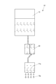
- FIG. 2 is a schematic diagram of the ink supply system 14 of the inkjet printer 10.
- the ink supply system 14 includes a recording head 11 c that discharges the ink 10 c to the recording medium 90, the above-described tank 13 that supplies the ink 10 c, and the ink 10 c that is supplied from the tank 13. And a damper device 20 that supplies the recording head 11c with the above-described control.
- the recording head 11c and the damper device 20 are mounted on the carriage 11b.
- the inkjet printer 10 includes a recording head 11c, a tank 13, and a damper device 20 for at least each type of ink 10c.
- the type of ink 10c is different depending on the type of color, such as cyan, magenta, yellow, and black.
- the ink jet printer 10 shown in FIG. 1 records the ink 10c from the nozzles of the recording head 11c by moving the recording head 11c in the main scanning direction by the carriage 11b with respect to the recording medium 90 that does not move in the main scanning direction indicated by the arrow 10a.
- This is an apparatus that executes printing in the main scanning direction by the recording head 11c by discharging toward the medium 90.
- the inkjet printer 10 transports the recording medium 90 in the sub-scanning direction by the transport device 12 to the recording head 11c that does not move in the sub-scanning direction indicated by the arrow 10b, so that the sub-scan of the recording head 11c with respect to the recording medium 90 is performed.
- This is a device that changes the position in the direction every time printing in the main scanning direction ends.
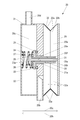
- FIG. 3 is a front sectional view of the damper device 20 when the valves 23 and 26 close the communication passages 20e and 20f, respectively.
- the damper device 20 communicates with the tank 13, a head side chamber 20 a communicating with the recording head 11 c, a channel 20 b constituting a part of a channel communicating with the recording head 11 c and the head side chamber 20 a, and the tank 13.
- FIG. 4 is a front view of the damper device 20 when the valves 23 and 26 close the communication passages 20e and 20f, respectively.
- FIG. 5 is a plan view of the damper device 20 when the valves 23 and 26 close the communication passages 20e and 20f, respectively.
- the damper device 20 includes a case 21 in which a flow path 20b and a flow path 20d are formed, a lid 22 fixed to the case 21, and a valve for opening and closing the communication path 20e.
- a spring 22 as a biasing member that is fixed to the lid 22 and the valve 23 and biases the valve 23 in a direction indicated by an arrow 20g that the valve 23 closes the communication path 20e, and a valve that is fixed to the case 21
- an O-ring 25 for preventing leakage of the ink 10c between the case 21 and the valve
- a spring 27 as a biasing member that biases the valve 26 in a direction indicated by an arrow 20g that is fixed to the valve 26 and closes the communication passage 20f, and a valve 26 that is fixed to the valve 23 closes the communication passage 20f.
- a rod member 31 is provided as a force transmitting portion that transmits a force received from one of the valve 26 and the pressure receiving plate 29 to the other, and a bellows portion 32 that supports the pressure receiving plate 29 so that the position of the pressure receiving plate 29 can be changed. ing.
- the head side chamber 20 a is formed by a case 21, a pressure receiving plate 29, and a bellows portion 32.
- the tank side chamber 20 c is formed by a case 21 and a lid 22.
- the communication path 20 e is formed by a case 21 and a rod member 30.
- the cross-sectional area of the communication path 20e is such that the communication path 20e and the communication path 20e from the tank side chamber 20c to the head side chamber 20a in a state where the communication path 20e is opened by the valve 23 and the communication path 20f is also opened by the valve 26.
- the cross-sectional area is such that the amount of ink 10c introduced through the passage 20f does not become larger than the amount of ink 10c reduced in the head side chamber 20a due to the ejection of the ink 10c by the recording head 11c.
- the sum of the cross-sectional area of the communication path 20e and the cross-sectional area of the communication path 20f is determined by the amount of ink 10c introduced from the tank side chamber 20c to the head side chamber 20a and the ink 10c through the communication path 20f.
- This is a sufficiently large area that does not become larger than the reduction amount of the ink 10c in the head side chamber 20a due to the ejection of the ink 10c.
- the communication path 20 f is formed by a valve 23, a rod member 30 and a rod member 31. That is, the valve 23 is formed with a communication passage 20 f that is opened and closed by the valve 26.
- the cross-sectional area of the communication passage 20f is such that the communication passage 20e is closed by the valve 23 and the communication passage 20f is opened by the valve 26, and depending on the discharge amount of the ink 10c from the recording head 11c, This is a cross-sectional area in which the amount of ink 10c introduced into the side chamber 20a through the communication path 20f may be larger than the amount of ink 10c in the head side chamber 20a reduced due to the ejection of the ink 10c by the recording head 11c.
- the case 21 has a hole 21a into which the rod member 30 is inserted.
- the case 21 is made of a synthetic resin such as polyethylene.
- the lid 22 is made of a synthetic resin such as polyethylene.
- the lid 22 is fixed to the case 21 with an adhesive.
- the valve 23 is formed as one part made of synthetic resin such as polyethylene together with the rod member 30.
- the valve 23 has a hole 23a into which the rod member 31 is inserted.
- the valve 26 is formed as a single component made of a synthetic resin such as polyethylene together with the rod member 31.
- the pressure receiving plate 29 is made of a synthetic resin such as polyethylene.
- the pressure receiving plate 29 does not have flexibility.
- the rod member 30 is formed with a hole 30a into which the rod member 31 is inserted and a notch 30b for communicating the head side chamber 20a and the hole 30a when the rod member 30 contacts the pressure receiving plate 29.
- valve 23, the spring 24, the O-ring 25, and the rod member 30 are provided for the communication path 20e.
- valve 26, the spring 27, the O-ring 28, and the rod member 31 are provided for the communication path 20f.
- the distance between the pressure receiving plate 29 and the rod member 30 is longer than the distance between the pressure receiving plate 29 and the rod member 31.
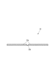
- FIG. 6 is a cross-sectional view of a part of the bellows portion 32.
- FIG. 7 is a development view of the bellows portion 32.
- the bellows portion 32 includes eight plate portions 32a and a bendable connection portion 32b that can be bent to connect the plate portions 32a.
- the plate portion 32a is formed by overlapping a flexible film member 32c and a plate-like member 32d fixed on the film member 32c with an adhesive.
- the bendable connection portion 32b is formed by a film member 32c.
- the plate-like member 32d is formed of a synthetic resin such as polyethylene.
- the plate-like member 32d does not have flexibility.
- the shape of the plate-like member 32d is a trapezoid.
- the two plate-like members 32d at the right end and the two plate-like members 32d at the left end in FIG. 7 are connected to each other via a flexible film member (not shown) fixed to itself with an adhesive.
- a flexible film member (not shown) fixed to itself with an adhesive.
- the case 21 and the bellows portion 32 are connected to each other via a flexible film member (not shown) fixed to itself with an adhesive. That is, the bellows portion 32 is connected to the case 21 via the film member so as to be bent. As this film member, a part of the film member 32c may be substituted.
- the pressure receiving plate 29 and the bellows portion 32 are connected to each other via a flexible film member (not shown) fixed to itself with an adhesive. That is, the bellows portion 32 is connected to the pressure receiving plate 29 via the film member so as to be bent. As this film member, a part of the film member 32c may be substituted.
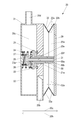
- FIG. 8 is a front sectional view of the damper device 20 when the valve 26 opens the communication path 20f.
- the position of the pressure receiving plate 29 shown in FIG. 3 is the position of the pressure receiving plate 29 when the rod member 31 can transmit the force received from one of the valve 26 and the pressure receiving plate 29 to the other.
- the position of the pressure receiving plate 29 shown in FIG. 8 is the position of the pressure receiving plate 29 when the rod member 30 can transmit the force received from one of the valve 23 and the pressure receiving plate 29 to the other.
- the position of the pressure receiving plate 29 shown in FIG. 3 is different from the position of the pressure receiving plate 29 shown in FIG.
- the rod member 31 is inserted into the hole 23 a of the valve 23 and the hole 30 a of the rod member 30, and the spring 27 is fixed to the valve 26.
- the lid 22 is fixed to the case 21 with an adhesive. Therefore, the spring 24 is fixed to the lid 22 and the valve 23, and the spring 27 is fixed to the lid 22 and the valve 26.
- the bellows portion 32 is fixed to the case 21 and the pressure receiving plate 29 with an adhesive.
- the recording head 11c ejects the ink 10c
- the amount of the ink 10c in the head side chamber 20a of the damper device 20 decreases.
- the volume of the head side chamber 20a decreases, so that the pressure receiving plate 29 moves in the direction indicated by the arrow 20h as the bellows portion 32 contracts.
- the valve 26 is the sum of the force received from the pressure receiving plate 29 via the rod member 31 and the force received by the pressure of the ink 10c on the communication path 20f side.
- the valve 26 receives the force received from the spring 27 by the sum of the force received from the pressure receiving plate 29 via the rod member 31 and the pressure of the ink 10c on the communication path 20f side, and the pressure of the ink 10c in the tank side chamber 20c. When it becomes larger than the sum of the forces received by the movement, it moves in the direction indicated by the arrow 20h. That is, the valve 26 opens the communication path 20f. At this time, the pressure receiving plate 29 pressing the valve 26 in the direction indicated by the arrow 20h via the rod member 31 moves in the direction indicated by the arrow 20h as the valve 26 moves in the direction indicated by the arrow 20h. Further, the bellows portion 32 contracts as the pressure receiving plate 29 moves in the direction indicated by the arrow 20h.
- the damper device 20 changes from the state shown in FIG. 3 to the state shown in FIG.
- the ink 10c in the tank side chamber 20c is applied with a high pressure because the tank 13 is located at a higher position than the tank side chamber 20c. Therefore, when the communication path 20f is opened, the ink 10c is introduced into the head side chamber 20a through the communication path 20f.
- the notch 30 b of the rod member 30 communicates with the head side chamber 20 a and the hole 30 a, so that the communication path 20 f includes the pressure receiving plate 29 and the rod member 30. It is not closed by contact with.
- the amount of ink 10c introduced from the tank side chamber 20c into the head side chamber 20a is larger than the amount of ink 10c in the head side chamber 20a reduced by the ejection of the ink 10c by the recording head 11c, the amount of ink 10c in the head side chamber 20a increases.
- the volume of the head side chamber 20a increases, so that the pressure receiving plate 29 moves in the direction indicated by the arrow 20g with the expansion of the bellows portion 32.
- the damper device 20 changes from the state shown in FIG. 8 to the state shown in FIG. 3 again.
- the head side chamber 20a when the amount of ink 10c introduced from the tank side chamber 20c to the head side chamber 20a is smaller than the reduction amount of the ink 10c in the head side chamber 20a due to the ejection of the ink 10c by the recording head 11c, the head side chamber 20a.
- the amount of the ink 10c decreases.
- the volume of the head side chamber 20a decreases, so that the pressure receiving plate 29 moves in the direction indicated by the arrow 20h as the bellows portion 32 contracts.
- the valve 23 is the sum of the force received from the pressure receiving plate 29 via the rod member 30 and the force received by the pressure of the ink 10c on the communication path 20e side. Cannot move in the direction indicated by the arrow 20h when the force received from the spring 24 and the force received by the pressure of the ink 10c in the tank side chamber 20c are equal to or less than the sum.
- the pressure receiving plate 29 connected to the valve 23 via the rod member 30 cannot move in the direction indicated by the arrow 20h.
- the pressure of the ink 10c in the head side chamber 20a decreases because the volume of the head side chamber 20a remains constant.
- the valve 23 receives the force received from the spring 24 by the sum of the force received from the pressure receiving plate 29 via the rod member 30 and the pressure of the ink 10c on the communication path 20e side, and the pressure of the ink 10c in the tank side chamber 20c. When it becomes larger than the sum of the forces received by the movement, it moves in the direction indicated by the arrow 20h. That is, the valve 23 opens the communication path 20e. At this time, the pressure receiving plate 29 pushing the valve 23 in the direction indicated by the arrow 20h via the rod member 30 moves in the direction indicated by the arrow 20h as the valve 23 moves in the direction indicated by the arrow 20h. Further, the bellows portion 32 contracts as the pressure receiving plate 29 moves in the direction indicated by the arrow 20h.
- the damper device 20 changes from the state shown in FIG. 8 to the state shown in FIG.
- FIG. 9 is a front sectional view of the damper device 20 when the valves 23 and 26 open the communication passages 20e and 20f, respectively.
- the ink 10c in the tank side chamber 20c is applied with a high pressure due to the presence of the tank 13 at a higher position than the tank side chamber 20c, when the damper device 20 enters the state shown in FIG. 9, the head passes through the communication path 20e. It is introduced into the side chamber 20a.
- the communication path 20e is formed by the ink 10c from the tank side chamber 20c to the head side chamber 20a in a state where the communication path 20e is opened by the valve 23 and the communication path 20f is also opened by the valve 26.
- the introduction amount is formed with a cross-sectional area that does not become larger than the reduction amount of the ink 10c in the head side chamber 20a due to the ejection of the ink 10c by the recording head 11c. Therefore, when the ink 10c is introduced from the tank side chamber 20c to the head side chamber 20a, the amount of the ink 10c in the head side chamber 20a increases. As the amount of the ink 10c in the head side chamber 20a increases, the volume of the head side chamber 20a increases, so that the pressure receiving plate 29 moves in the direction indicated by the arrow 20g with the expansion of the bellows portion 32.
- the damper device 20 changes from the state shown in FIG. 9 to the state shown in FIG. 8 again.
- the cross-sectional area of the communication path opened by the valves 23 and 26 changes in accordance with the amount of ink 10c in the head side chamber 20a.
- the damper device 20 only includes the communication path 20f when the amount of reduction of the ink 10c in the head-side chamber 20a is small. Is opened by the valve 26, and a small amount of ink 10c is introduced from the tank side chamber 20c to the head side chamber 20a through the communication path 20f.
- the damper device 20 when the inkjet printer 10 performs printing with a large amount of ink 10c used, such as solid printing, when the amount of ink 10c in the head side chamber 20a is large, the damper device 20 is connected to the communication path 20f. Further, the communication passage 20e is opened by the valve 23 with the valve 26 opened, and a large amount of ink 10c is introduced from the tank side chamber 20c to the head side chamber 20a through the communication passage 20e and the communication passage 20f. Therefore, the damper device 20 can make the fluctuation of the pressure of the ink 10c in the head side chamber 20a smaller than before, and expand the range of the ejection amount where the accuracy of ejection of the ink 10c by the recording head 11c is stable than before. can do.
- the O-ring 25 may be deteriorated by the influence of the ink 10c and may stick to the valve 23 and become difficult to separate.
- the O-ring 28 may deteriorate due to the influence of the ink 10c, and may stick to the valve 26 and become difficult to separate.
- the area of the valve 26 is smaller than that of the valve 23, the force received by the pressure of the ink 10c in the tank side chamber 20c is small. That is, when the valve 26 is pushed from the pressure receiving plate 29 through the rod member 31 in the direction indicated by the arrow 20h, the valve 26 is moved with a greater force in the direction indicated by the arrow 20h than the valve 23. Therefore, the valve 26 can be easily separated from the O-ring 28 as compared with the valve 23 even if the valve 26 is attached to the O-ring 28 that has been altered by the influence of the ink 10c.
- the damper device 20 is a case where a valve capable of transmitting a force to the pressure receiving plate 29 via the rod member is changed from only the valve 26 to both the valve 23 and the valve 26 due to a change in the position of the pressure receiving plate 29.
- a valve capable of transmitting a force to the pressure receiving plate 29 via the rod member is changed from only the valve 26 to both the valve 23 and the valve 26 due to a change in the position of the pressure receiving plate 29.
- fluctuations in the location of the portion of the pressure receiving plate 29 that receives the force from the rod member can be suppressed.
- the damper device 20 can smoothly change the position of the pressure receiving plate 29.
- the damper device 20 includes the bellows portion 32 that supports the pressure receiving plate 29 so that the position of the pressure receiving plate 29 can be changed, a large change in the position of the pressure receiving plate 29 in the direction indicated by the arrow 20g or the arrow 20h. Can be easily realized by a large stroke of the bellows portion 32.
- the damper device 20 does not change the position of the pressure receiving plate 29 by deformation of the flexible film member itself as in the third embodiment described later, but instead of changing the position of the pressure receiving plate 29 by deformation of the bellows portion 32. Since the position is changed, a film member 232 described later that supports the pressure receiving plate 29 so as to extend in a direction orthogonal to the direction indicated by the arrow 20g or the arrow 20h and to change the position of the pressure receiving plate 29 (FIG. 17). A flexible film member such as (see) is not necessary. Therefore, the damper device 20 can be made smaller in size in the direction orthogonal to the direction indicated by the arrow 20g or the arrow 20h than in the prior art.
- the damper device 20 extends in a direction perpendicular to the direction indicated by the arrow 20g or the arrow 20h, and a film member 232 (described later) that supports the pressure receiving plate 29 so that the position of the pressure receiving plate 29 can be changed. 17) is not required, the area of the pressure receiving plate 29 in the direction orthogonal to the direction indicated by the arrow 20g or the arrow 20h can be made larger than that in the third embodiment described later. it can. Therefore, the damper device 20 can easily receive the force necessary for the valves 23 and 26 to open the communication passages 20e and 20f by the pressure receiving plate 29 by atmospheric pressure.
- FIG. 10 is a cross-sectional view of a part of the bellows portion 32 and shows an example different from the example shown in FIG.
- the bellows portion 32 described above has the structure shown in FIG. However, the bellows portion 32 may have the structure shown in FIG.
- the bellows portion 32 includes a plate portion 32 a and a bendable bendable connection portion 32 b that connects the plate portions 32 a as a single part made of a synthetic resin such as polyethylene.
- the bendable connection portion 32b is formed thinner than the plate portion 32a so as to be bendable.
- the plate portion 32a and the bendable connection portion 32b can be manufactured by integral molding of synthetic resin. Therefore, in the damper device 20, when the bellows portion 32 has the structure shown in FIG. 10, the manufacturing cost can be reduced, for example, compared with the case where the bellows portion 32 has the structure shown in FIG.
- FIG. 11 is a front sectional view of the damper device 20 when the valves 23 and 26 close the communication passages 20e and 20f, respectively, and is a diagram showing an example different from the example shown in FIG.
- the damper device 20 may include a spring 33 between the case 21 and the pressure receiving plate 29 as shown in FIG.
- the damper device 20 has the structure shown in FIG. 11, the pressure of the ink 10c in the head side chamber 20a can be reliably maintained at a negative pressure with respect to the atmospheric pressure.
- FIG. 12 is a front sectional view of the damper device 20 when the valves 23 and 26 close the communication passages 20e and 20f, respectively, and is a diagram showing an example different from the examples shown in FIGS.
- the rod member 31 described above is formed as one part made of synthetic resin such as polyethylene together with the valve 26.
- the rod member 31 may be formed as a single component made of synthetic resin such as polyethylene together with the pressure receiving plate 29 as shown in FIG.
- FIG. 13 is a front cross-sectional view of the damper device 20 when the valves 23 and 26 close the communication passages 20e and 20f, respectively, and is a diagram showing an example different from the examples shown in FIGS. It is.
- the rod member 30 described above is formed as one part made of a synthetic resin such as polyethylene together with the valve 23.
- the rod member 30 may be formed as a single component made of synthetic resin such as polyethylene together with the pressure receiving plate 29.
- FIG. 14 is a front sectional view of the damper device 120 of the ink jet printer according to the present embodiment when the valves 123 and 126 close the communication passages 120e and 120f, respectively.
- the configuration of the inkjet printer according to the present embodiment is the same as the configuration in which the inkjet printer 10 (see FIG. 1) includes the damper device 120 shown in FIG. 14 instead of the damper device 20 (see FIG. 3).
- the communication passage 120e and the communication passage 120f that communicate the head side chamber 20a and the tank side chamber 20c are the communication passage 20e (see FIG. 3) and the communication passage 20f (see FIG. 3). It is formed instead of.
- the damper device 120 includes a case 121 in which a flow path 20b and a flow path 20d are formed, a lid 122 fixed to the case 121, and a valve 123 for opening and closing the communication path 120e.
- a spring 124 as a biasing member that is fixed to the lid 122 and the valve 123 and biases the valve 123 in a direction indicated by an arrow 20g that closes the communication passage 120e, and a valve 123 that is fixed to the case 121.
- the O-ring 125 for preventing leakage of the ink 10c between the case 121 and the valve 123, the valve 126 for opening and closing the communication path 120f, and the lid 122 and the valve 126 are fixed.
- the rod member 131 serving as a force transmitting portion that transmits the force received to the other side includes a case 21 (see FIG. 3), a lid 22 (see FIG. 3), a valve 23 (see FIG. 3), and a spring 24 (see FIG. 3). Reference), O-ring 25 (see FIG. 3), valve 26 (see FIG. 3), spring 27 (see FIG. 3), O-ring 28 (see FIG. 3), rod member 30 (see FIG. 3). ) And rod member 31 Has instead see FIG.).
- the head side chamber 20 a is formed by a case 121, a pressure receiving plate 29, and a bellows portion 32.
- the tank side chamber 20c is formed by a case 121 and a lid 122.
- the communication path 120e is formed by a case 121 and a rod member 130.
- the cross-sectional area of the communication path 120e is such that the communication path 120e and the communication path 120e from the tank side chamber 20c to the head side chamber 20a in the state where the communication path 120e is opened by the valve 123 and the communication path 120f is also opened by the valve 126.
- the cross-sectional area is such that the introduction amount of the ink 10c through the passage 120f does not become larger than the reduction amount of the ink 10c in the head side chamber 20a due to the ejection of the ink 10c by the recording head 11c.
- the sum of the cross-sectional area of the communication path 120e and the cross-sectional area of the communication path 120f is determined by the amount of ink 10c introduced from the tank side chamber 20c to the head side chamber 20a and the ink 10c through the communication path 120f.
- This is a sufficiently large area that does not become larger than the reduction amount of the ink 10c in the head side chamber 20a due to the ejection of the ink 10c.
- the communication path 120f is formed by a case 121 and a rod member 131.
- the cross-sectional area of the communication path 120f is such that the communication path 120e is closed by the valve 123 and the communication path 120f is opened by the valve 126, and depending on the discharge amount of the ink 10c by the recording head 11c, This is a cross-sectional area in which the amount of ink 10c introduced into the side chamber 20a through the communication path 120f may be larger than the amount of ink 10c in the head side chamber 20a reduced due to the ejection of the ink 10c by the recording head 11c.
- the case 121 has a hole 121a into which the rod member 130 is inserted and a hole 121b into which the rod member 131 is inserted.
- the case 121 is formed of a synthetic resin such as polyethylene.
- the lid 122 is made of a synthetic resin such as polyethylene.
- the lid 122 is fixed to the case 121 with an adhesive.
- the valve 123 is formed as one part made of synthetic resin such as polyethylene together with the rod member 130.
- the valve 126 is formed as a single component made of a synthetic resin such as polyethylene together with the rod member 131.
- the valve 123, the spring 124, the O-ring 125, and the rod member 130 are provided for the communication path 120e.
- the valve 126, the spring 127, the O-ring 128, and the rod member 131 are provided for the communication path 120f.
- the distance between the pressure receiving plate 29 and the rod member 130 is longer than the distance between the pressure receiving plate 29 and the rod member 131.
- the case 121 and the bellows portion 32 are connected to each other via a flexible film member (not shown) fixed to itself with an adhesive. That is, the bellows portion 32 is connected to the case 121 via the film member so as to be bent. As this film member, a part of the film member 32c of the bellows portion 32 may be substituted.
- FIG. 15 is a front sectional view of the damper device 120 when the valve 126 opens the communication path 120f.
- the position of the pressure receiving plate 29 shown in FIG. 14 is the position of the pressure receiving plate 29 when the rod member 131 can transmit the force received from one of the valve 126 and the pressure receiving plate 29 to the other.
- the position of the pressure receiving plate 29 shown in FIG. 15 is the position of the pressure receiving plate 29 when the rod member 130 can transmit the force received from one of the valve 123 and the pressure receiving plate 29 to the other.
- the position of the pressure receiving plate 29 shown in FIG. 14 is different from the position of the pressure receiving plate 29 shown in FIG.
- FIG. 16 is a front sectional view of the damper device 120 when the valves 123 and 126 open the communication passages 120e and 120f, respectively.
- the damper device 120 includes the introduction of the ink 10c from the tank side chamber 20c to the head side chamber 20a and the discharge of the ink 10c from the head side chamber 20a to the recording head 11c.
- the state shown in FIGS. 14, 15 and 16 is changed according to the situation.
- the cross-sectional area of the communication path opened by the valves 123 and 126 changes in accordance with the amount of reduction of the ink 10c in the head side chamber 20a.
- the damper device 120 is used when the amount of ink 10c in the head side chamber 20a is small. Then, only the communication path 120f is opened by the valve 126, and a small amount of ink 10c is introduced from the tank side chamber 20c to the head side chamber 20a via the communication path 120f.
- the damper device 120 In the state where the communication path 120f is opened by the valve 126, the communication path 120e is further opened by the valve 123, and a large amount of ink 10c is introduced from the tank side chamber 20c to the head side chamber 20a via the communication path 120e and the communication path 120f. .
- the damper device 120 can make the fluctuation of the pressure of the ink 10c in the head side chamber 20a smaller than before, and expand the range of the ejection amount where the accuracy of ejection of the ink 10c by the recording head 11c is stable than before. can do.
- FIG. 17 is a front sectional view of the damper device 220 of the ink jet printer according to the present embodiment when the valves 23 and 26 close the communication passages 20e and 20f, respectively.
- FIG. 18 is a front view of the damper device 220 when the valves 23 and 26 close the communication passages 20e and 20f, respectively.
- FIG. 19 is a plan view of the damper device 220 when the valves 23 and 26 close the communication passages 20e and 20f, respectively.
- the configuration of the inkjet printer according to the present embodiment is the same as the configuration in which the inkjet printer 10 (see FIG. 1) includes the damper device 220 shown in FIGS. 17 to 19 instead of the damper device 20 (see FIG. 3). It is.
- the damper device 220 is a case 221 in which the flow channel 20b and the flow channel 20d are formed, and a pressure receiving unit that receives the atmospheric pressure and changes the volume of the head side chamber 20a by a change in its position.
- the bellows portion 32 see FIG. 3).
- the head side chamber 20 a is formed by a case 221, a pressure receiving plate 229 and a film member 232.
- the tank side chamber 20 c is formed by a case 221 and a lid 22.
- the case 221 is made of a synthetic resin such as polyethylene.
- the case 221, the lid 22 is fixed with an adhesive.
- the pressure plate 229 is made of a synthetic resin such as polyethylene.
- the pressure receiving plate 229 does not have flexibility.
- the pressure receiving plate 229 is fixed to the film member 232 with an adhesive.
- the distance between the pressure receiving plate 229 and the rod member 30 is longer than the distance between the pressure receiving plate 229 and the rod member 31.
- the film member 232 is fixed to the case 221 with an adhesive.
- FIG. 20 is a front sectional view of the damper device 220 when the valve 26 opens the communication passage 20f.
- the position of the pressure receiving plate 229 shown in FIG. 17 is the position of the pressure receiving plate 229 when the rod member 31 can transmit the force received from one of the valve 26 and the pressure receiving plate 229 to the other.
- the position of the pressure receiving plate 229 shown in FIG. 20 is the position of the pressure receiving plate 229 when the rod member 30 can transmit the force received from one of the valve 23 and the pressure receiving plate 229 to the other.
- the position of the pressure receiving plate 229 shown in FIG. 17 is different from the position of the pressure receiving plate 229 shown in FIG.
- the rod member 31 is inserted into the hole 23 a of the valve 23 and the hole 30 a of the rod member 30, and the spring 27 is fixed to the valve 26.
- the lid 22 is fixed to the case 221 with an adhesive. Therefore, the spring 24 is fixed to the lid 22 and the valve 23, and the spring 27 is fixed to the lid 22 and the valve 26.
- FIG. 21 is a front sectional view of the damper device 220 when the valves 23 and 26 open the communication passages 20e and 20f, respectively.
- the damper device 220 is configured to introduce the ink 10c from the tank side chamber 20c to the head side chamber 20a and discharge the ink 10c from the head side chamber 20a to the recording head 11c.
- the states shown in FIGS. 17, 20, and 21 are changed depending on the situation.
- the cross-sectional area of the communication path opened by the valves 23 and 26 changes in accordance with the amount of reduction of the ink 10c in the head side chamber 20a.
- the damper device 220 is Then, only the communication path 20f is opened by the valve 26, and a small amount of ink 10c is introduced from the tank side chamber 20c to the head side chamber 20a through the communication path 20f.
- the damper device 220 is used.
- the communication path 20f is opened by the valve 26
- the communication path 20e is further opened by the valve 23, and a large amount of ink 10c is introduced from the tank side chamber 20c to the head side chamber 20a via the communication path 20e and the communication path 20f. .
- the damper device 220 can make the fluctuation of the pressure of the ink 10c in the head side chamber 20a smaller than before, and expand the range of the ejection amount where the accuracy of ejection of the ink 10c by the recording head 11c is stable than before. can do.
- the damper device in each of the above-described embodiments includes two valves, so that the operation of introducing the ink 10c from the tank side chamber 20c to the head side chamber 20a is a two-stage operation in which the amount of ink 10c introduced is different. That is, an operation for introducing a small amount of ink 10c and an operation for introducing a large amount of ink 10c are executed.
- the damper device is provided with more than two valves, so that the operation of introducing the ink 10c from the tank side chamber 20c to the head side chamber 20a is the operation of the flow rate in more stages than two stages in which the introduction amount of the ink 10c is different. You may come to perform.
- the damper device in each of the above-described embodiments is configured to supply the ink 10c supplied from the tank 13 to the recording head 11c while suppressing fluctuations in pressure.
- the damper device may supply liquid other than the ink 10c to the recording head 11c.
- the damper device may supply the cleaning liquid supplied from the tank 13 to the recording head 11c.
- the damper device may perform an operation of introducing a large amount of cleaning liquid.
- the O-ring in each of the above-described embodiments functions to block the flow path of the ink 10c when the valve closes the communication path. Therefore, the damper device in each of the above-described embodiments may be configured such that the flow path of the ink 10c when the valve closes the communication path is blocked by a sealing material other than the O-ring, The sealing may be performed by pressing the valve itself without providing a sealing material such as an O-ring.
- a sealing material for example, a rubber sealing material can be employed.
Landscapes
- Ink Jet (AREA)
Abstract
記録ヘッドによるインクの吐出の精度が安定している吐出量の範囲を従来より拡大することができるダンパー装置を提供することを課題とする。 解決手段として、ダンパー装置(20)は、連通路(20e、20f)を開閉するための弁(23、26)と、弁(23、26)が連通路(20e、20f)を閉じる方向に弁(23、26)を付勢するバネ(24、27)と、大気圧を受けるとともに自身の位置の変化によってヘッド側室(20a)の容積を変化させる受圧板(29)と、弁(23、26)および受圧板(29)の間に配置されて弁(23、26)および受圧板(29)の一方から受ける力を他方に伝達するロッド部材(30、31)とを備えており、受圧板(29)の位置は、ロッド部材(30、31)のそれぞれが弁(23、26)および受圧板(29)の一方から受ける力を他方に伝達可能となる時点毎に異なり、弁によって開かれている連通路の断面積の合計は、弁の開閉状況に応じて異なることを特徴とする。
Description
本発明は、インクを吐出する記録ヘッドと、インクを供給するタンクとを備えるインクジェットプリンターに備えられて、タンクから供給されるインクを圧力の変動を抑えて記録ヘッドに供給するダンパー装置に関する。
従来のダンパー装置として、記録ヘッドに連通するヘッド側室としての圧力室と、タンクとしてのインクカートリッジに連通するタンク側室としてのインク供給室と、圧力室およびインク供給室を連通する連通路としてのインク供給孔とが形成されており、インク供給孔を開閉するための弁としての板状部材と、板状部材がインク供給孔を閉じる方向に板状部材を付勢するバネとしてのシールバネと、大気圧を受けるとともに自身の位置の変化によって圧力室の容積を変化させる受圧部としての受圧板と、板状部材および受圧板の間に配置されて板状部材および受圧板の一方から受ける力を他方に伝達する力伝達部としてのロッド部材とを備えているバルブユニットが知られている(特許文献1参照。)。
しかしながら、従来のダンパー装置においては、弁によって開かれる連通路の断面積がヘッド側室内のインクの減少量に関わらず常に一定であるので、ヘッド側室内のインクの圧力の変動が大きいという問題がある。例えば、従来のダンパー装置は、ヘッド側室内のインクの減少量が少ない場合には、弁が連通路を開いたとき、タンク側室からの連通路を介したヘッド側室へのインクの導入量が多過ぎるので、ヘッド側室内のインクの圧力が高くなり過ぎる。一方、従来のダンパー装置は、ヘッド側室内のインクの減少量が大きい場合には、弁が連通路を開いたとき、タンク側室からの連通路を介したヘッド側室へのインクの導入量が少な過ぎるので、ヘッド側室内のインクの圧力が低くなり過ぎる。
そして、従来のダンパー装置は、ヘッド側室内のインクの圧力の変動が大きいので、記録ヘッドによるインクの吐出の精度が不安定であるという問題がある。
そこで、本発明は、記録ヘッドによるインクの吐出の精度が安定している吐出量の範囲を従来より拡大することができるダンパー装置を提供することを目的とする。
本発明のダンパー装置は、インクを吐出する記録ヘッドと、前記インクを供給するタンクとを備えるインクジェットプリンターに備えられて、前記タンクから供給される前記インクを圧力の変動を抑えて前記記録ヘッドに供給するダンパー装置であって、前記記録ヘッドに連通するヘッド側室と、前記タンクに連通するタンク側室と、前記ヘッド側室および前記タンク側室を連通する複数の連通路とが形成されており、前記連通路を開閉するための弁と、前記弁が前記連通路を閉じる方向に前記弁を付勢する付勢部材と、大気圧を受けるとともに自身の位置の変化によって前記ヘッド側室の容積を変化させる受圧部と、前記弁および前記受圧部の間に配置されて前記弁および前記受圧部の一方から受ける力を他方に伝達する力伝達部とを備えており、前記弁、前記付勢部材および前記力伝達部は、前記複数の連通路のそれぞれに対して備えられており、前記受圧部の位置は、複数の前記力伝達部のそれぞれが前記弁および前記受圧部の一方から受ける力を他方に伝達可能となる時点毎に異なり、前記弁によって開かれている前記連通路の断面積の合計は、前記弁の開閉状況に応じて異なることを特徴とする。
この構成により、本発明のダンパー装置は、弁によって開かれる連通路の断面積がヘッド側室内のインクの減少量に応じて変化するので、ヘッド側室内のインクの圧力の変動を従来より小さくすることができる。したがって、本発明のダンパー装置は、記録ヘッドによるインクの吐出の精度が安定している吐出量の範囲を従来より拡大することができる。
また、本発明のダンパー装置において、複数の前記弁の少なくとも1つは、他の前記弁によって開閉される前記連通路が形成されていても良い。
この構成により、本発明のダンパー装置は、弁が連通路を開閉する方向に直交する方向における複数の弁の中心を一致させることができるので、力伝達部を介して受圧部に力を伝達可能となる弁が受圧部の位置の変化によって変化した場合であっても、受圧部のうち力伝達部から力を受ける部分の場所の変動を抑えることができる。したがって、本発明のダンパー装置は、受圧部の位置を滑らかに変化させることができる。
また、本発明のダンパー装置は、前記受圧部の位置が変化可能であるように前記受圧部を支持する蛇腹部を備えていても良い。
この構成により、本発明のダンパー装置は、弁が連通路を開閉する方向への受圧部の大きな位置の変化を、蛇腹部の大きなストロークによって容易に実現することができる。
また、本発明のダンパー装置において、前記蛇腹部は、複数の板部と、前記板部同士を接続する屈曲可能な屈曲可能接続部とを備えており、前記板部および前記屈曲可能接続部は、合成樹脂製の1つの部品として形成されていても良い。
この構成により、本発明のダンパー装置は、板部および屈曲可能接続部が合成樹脂の一体成形によって製造されることができる。したがって、本発明のダンパー装置は、例えば製造コストを低減することができる。
本発明のダンパー装置は、記録ヘッドによるインクの吐出の精度が安定している吐出量の範囲を従来より拡大することができる。
以下、本発明の実施の形態について、図面を用いて説明する。
(第1の実施の形態)
まず、本実施の形態に係るインクジェットプリンターの構成について説明する。
まず、本実施の形態に係るインクジェットプリンターの構成について説明する。
図1は、本実施の形態に係るインクジェットプリンター10の斜視図である。
図1に示すように、インクジェットプリンター10は、矢印10aで示す主走査方向に延在する本体11と、用紙などの記録媒体90を搬送する搬送装置12と、インクを供給するタンク13とを備えている。
本体11は、矢印10aで示す主走査方向に延在しているガイドレール11aと、矢印10aで示す主走査方向に移動可能にガイドレール11aに支持されているキャリッジ11bとを備えている。
搬送装置12は、本体11の後述の記録ヘッド11cに対して矢印10bで示す副走査方向に記録媒体90を搬送する装置である。
図2は、インクジェットプリンター10のインク供給システム14の模式図である。
図2に示すように、インク供給システム14は、記録媒体90にインク10cを吐出する記録ヘッド11cと、インク10cを供給する上述のタンク13と、タンク13から供給されるインク10cを圧力の変動を抑えて記録ヘッド11cに供給するダンパー装置20とを備えている。
記録ヘッド11cおよびダンパー装置20は、キャリッジ11bに搭載されている。
インクジェットプリンター10は、記録ヘッド11c、タンク13およびダンパー装置20を少なくともインク10cの種類毎に備えている。インク10cの種類は、シアン、マゼンタ、イエロー、ブラックなど、例えば色の種類によって異なる。
図1に示すインクジェットプリンター10は、矢印10aで示す主走査方向に移動しない記録媒体90に対してキャリッジ11bによって主走査方向に記録ヘッド11cを移動させて、記録ヘッド11cのノズルからインク10cを記録媒体90に向けて吐出することによって、記録ヘッド11cによる主走査方向の印刷を実行させる装置である。また、インクジェットプリンター10は、矢印10bで示す副走査方向に移動しない記録ヘッド11cに対して搬送装置12によって副走査方向に記録媒体90を搬送することによって、記録媒体90に対する記録ヘッド11cの副走査方向における位置を主走査方向の印刷の終了の度に変更する装置である。
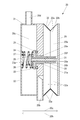
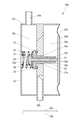
図3は、弁23、26がそれぞれ連通路20e、20fを閉じている場合のダンパー装置20の正面断面図である。
図3に示すように、ダンパー装置20は、記録ヘッド11cに連通するヘッド側室20aと、記録ヘッド11cおよびヘッド側室20aを連通する流路の一部を構成する流路20bと、タンク13に連通するタンク側室20cと、タンク13およびタンク側室20cを連通する流路の一部を構成する流路20dと、ヘッド側室20aおよびタンク側室20cを連通する連通路20eおよび連通路20fとが形成されている。
図4は、弁23、26がそれぞれ連通路20e、20fを閉じている場合のダンパー装置20の正面図である。図5は、弁23、26がそれぞれ連通路20e、20fを閉じている場合のダンパー装置20の平面図である。
図3~図5に示すように、ダンパー装置20は、流路20bおよび流路20dが形成されたケース21と、ケース21に固定されている蓋22と、連通路20eを開閉するための弁23と、蓋22および弁23に固定されていて弁23が連通路20eを閉じる矢印20gで示す方向に弁23を付勢する付勢部材としてのバネ24と、ケース21に固定されていて弁23が連通路20eを閉じている場合にケース21および弁23の間のインク10cの漏れを防止するためのOリング25と、連通路20fを開閉するための弁26と、蓋22および弁26に固定されていて弁26が連通路20fを閉じる矢印20gで示す方向に弁26を付勢する付勢部材としてのバネ27と、弁23に固定されていて弁26が連通路20fを閉じている場合に弁23および弁26の間のインク10cの漏れを防止するためのOリング28と、大気圧を受けるとともに自身の位置の変化によってヘッド側室20aの容積を変化させる受圧部としての受圧板29と、弁23および受圧板29の間に配置されて弁23および受圧板29の一方から受ける力を他方に伝達する力伝達部としてのロッド部材30と、弁26および受圧板29の間に配置されて弁26および受圧板29の一方から受ける力を他方に伝達する力伝達部としてのロッド部材31と、受圧板29の位置が変化可能であるように受圧板29を支持する蛇腹部32とを備えている。
ヘッド側室20aは、ケース21、受圧板29および蛇腹部32によって形成されている。
タンク側室20cは、ケース21および蓋22によって形成されている。
連通路20eは、ケース21およびロッド部材30によって形成されている。ここで、連通路20eの断面積は、連通路20eが弁23によって開かれていて連通路20fも弁26によって開かれている状態で、タンク側室20cからヘッド側室20aへの連通路20eおよび連通路20fを介したインク10cの導入量が、記録ヘッド11cによるインク10cの吐出によるヘッド側室20aのインク10cの減少量より多くなることがない断面積である。すなわち、連通路20eの断面積と、連通路20fの断面積との合計は、タンク側室20cからヘッド側室20aへの連通路20eおよび連通路20fを介したインク10cの導入量が、記録ヘッド11cによるインク10cの吐出によるヘッド側室20aのインク10cの減少量より多くなることがない十分に大きな面積である。
連通路20fは、弁23、ロッド部材30およびロッド部材31によって形成されている。すなわち、弁23は、弁26によって開閉される連通路20fが形成されている。連通路20fの断面積は、連通路20eが弁23によって閉ざされていて連通路20fが弁26によって開かれている状態で、記録ヘッド11cによるインク10cの吐出量によっては、タンク側室20cからヘッド側室20aへの連通路20fを介したインク10cの導入量が、記録ヘッド11cによるインク10cの吐出によるヘッド側室20aのインク10cの減少量より多くなる場合がある断面積である。
ケース21は、ロッド部材30が挿入される孔21aが形成されている。ケース21は、ポリエチレンなどの合成樹脂によって形成されている。
蓋22は、ポリエチレンなどの合成樹脂によって形成されている。蓋22は、ケース21に接着剤によって固定されている。
弁23は、ロッド部材30とともにポリエチレンなどの合成樹脂製の1つの部品として形成されている。弁23は、ロッド部材31が挿入される孔23aが形成されている。
弁26は、ロッド部材31とともにポリエチレンなどの合成樹脂製の1つの部品として形成されている。
受圧板29は、ポリエチレンなどの合成樹脂によって形成されている。受圧板29は、可撓性を有していない。
ロッド部材30は、ロッド部材31が挿入される孔30aと、ロッド部材30が受圧板29に接触する場合にヘッド側室20aおよび孔30aを連通するための切欠き30bとが形成されている。
弁23、バネ24、Oリング25およびロッド部材30は、連通路20eに対して備えられている。
弁26、バネ27、Oリング28およびロッド部材31は、連通路20fに対して備えられている。
弁23、26がそれぞれ連通路20e、20fを閉じている場合、受圧板29と、ロッド部材30との距離は、受圧板29と、ロッド部材31との距離より長い。
図6は、蛇腹部32の一部の断面図である。図7は、蛇腹部32の展開図である。
図6および図7に示すように、蛇腹部32は、8つの板部32aと、板部32a同士を接続する屈曲可能な屈曲可能接続部32bとを備えている。板部32aは、可撓性のフィルム部材32cと、フィルム部材32c上に接着剤によって固定された板状部材32dとの重なりによって形成されている。屈曲可能接続部32bは、フィルム部材32cによって形成されている。板状部材32dは、ポリエチレンなどの合成樹脂によって形成されている。板状部材32dは、可撓性を有していない。板状部材32dの形状は、台形である。
なお、図7中の右端の2つの板状部材32dと、左端の2つの板状部材32dとは、接着剤によって自身に固定された図示していない可撓性のフィルム部材を介して互いに接続されている。すなわち、右端の2つの板状部材32dと、左端の2つの板状部材32dとは、このフィルム部材を介して互いに屈曲可能に接続されている。このフィルム部材としては、フィルム部材32cの一部が代用されていても良い。
ケース21および蛇腹部32は、接着剤によって自身に固定された図示していない可撓性のフィルム部材を介して互いに接続されている。すなわち、蛇腹部32は、このフィルム部材を介してケース21に屈曲可能に接続されている。このフィルム部材としては、フィルム部材32cの一部が代用されていても良い。
受圧板29および蛇腹部32は、接着剤によって自身に固定された図示していない可撓性のフィルム部材を介して互いに接続されている。すなわち、蛇腹部32は、このフィルム部材を介して受圧板29に屈曲可能に接続されている。このフィルム部材としては、フィルム部材32cの一部が代用されていても良い。
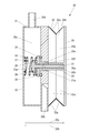
図8は、弁26が連通路20fを開いている場合のダンパー装置20の正面断面図である。
図3に示す受圧板29の位置は、ロッド部材31が弁26および受圧板29の一方から受ける力を他方に伝達可能となる時点の受圧板29の位置である。図8に示す受圧板29の位置は、ロッド部材30が弁23および受圧板29の一方から受ける力を他方に伝達可能となる時点の受圧板29の位置である。上述したように、弁23、26がそれぞれ連通路20e、20fを閉じている場合、受圧板29と、ロッド部材30との距離は、受圧板29と、ロッド部材31との距離より長い。したがって、図3に示す受圧板29の位置と、図8に示す受圧板29の位置とは異なる。
次に、ダンパー装置20の製造方法について説明する。
まず、弁23にOリング28が固定された後、弁23の孔23aおよびロッド部材30の孔30aにロッド部材31が挿入されて、弁26にバネ27が固定される。
次いで、ケース21にOリング25が固定された後、ケース21の孔21aにロッド部材30が挿入されて、弁23にバネ24が固定される。
次いで、蓋22がケース21に接着剤によって固定される。したがって、バネ24は、蓋22および弁23に固定され、バネ27は、蓋22および弁26に固定される。
最後に、蛇腹部32がケース21および受圧板29に接着剤によって固定される。
次に、ダンパー装置20の動作について説明する。
記録ヘッド11cがインク10cを吐出すると、ダンパー装置20のヘッド側室20aのインク10cの量が減少する。ヘッド側室20aのインク10cの量が減少すると、ヘッド側室20aの容積が減少するので、受圧板29は、蛇腹部32の収縮に伴って、矢印20hで示す方向に移動する。ここで、弁26は、受圧板29がロッド部材31に接触している場合、ロッド部材31を介して受圧板29から受ける力と、連通路20f側のインク10cの圧力によって受ける力との合計が、バネ27から受ける力と、タンク側室20cのインク10cの圧力によって受ける力との合計以下であるとき、矢印20hで示す方向に移動することができない。弁26が矢印20hで示す方向に移動することができない場合、ロッド部材31を介して弁26に接続されている受圧板29も、矢印20hで示す方向に移動することができない。受圧板29が矢印20hで示す方向に移動することができない場合、ヘッド側室20aのインク10cは、ヘッド側室20aの容積が一定のまま量が減少するので、圧力が低下する。
ヘッド側室20aのインク10cの圧力が低下すると、ヘッド側室20aのインク10cの圧力および大気圧を受けている受圧板29がロッド部材31を介して弁26を押す力が増加する。
弁26は、ロッド部材31を介して受圧板29から受ける力と、連通路20f側のインク10cの圧力によって受ける力との合計が、バネ27から受ける力と、タンク側室20cのインク10cの圧力によって受ける力との合計よりも大きくなると、矢印20hで示す方向に移動する。すなわち、弁26は、連通路20fを開く。このとき、ロッド部材31を介して弁26を矢印20hで示す方向に押している受圧板29は、矢印20hで示す方向への弁26の移動に伴って、矢印20hで示す方向に移動する。また、蛇腹部32は、矢印20hで示す方向への受圧板29の移動に伴って収縮する。
したがって、ダンパー装置20は、図3に示す状態から、図8に示す状態に変化する。
タンク側室20c内のインク10cは、タンク13がタンク側室20cより高い位置に存在することによって高い圧力が加わっているので、連通路20fが開くと、連通路20fを通ってヘッド側室20aに導入される。ここで、ダンパー装置20が図8に示す状態になった場合も、ロッド部材30の切欠き30bがヘッド側室20aおよび孔30aを連通するので、連通路20fは、受圧板29と、ロッド部材30との接触によって閉じられることがない。
タンク側室20cからヘッド側室20aへのインク10cの導入量が、記録ヘッド11cによるインク10cの吐出によるヘッド側室20aのインク10cの減少量より多い場合、ヘッド側室20aのインク10cの量は増加する。ヘッド側室20aのインク10cの量が増加すると、ヘッド側室20aの容積が増加するので、受圧板29は、蛇腹部32の伸張を伴って、矢印20gで示す方向に移動する。
受圧板29が矢印20gで示す方向に移動すると、ロッド部材31を介して受圧板29にバネ27の付勢力によって押し付けられている弁26は、矢印20gで示す方向への受圧板29の移動に伴って、矢印20gで示す方向に移動する。すなわち、弁26は、連通路20fを閉じる。
したがって、ダンパー装置20は、図8に示す状態から、再び図3に示す状態に変化する。
一方、図8に示す状態において、タンク側室20cからヘッド側室20aへのインク10cの導入量が、記録ヘッド11cによるインク10cの吐出によるヘッド側室20aのインク10cの減少量より小さい場合、ヘッド側室20aのインク10cの量は減少する。ヘッド側室20aのインク10cの量が減少すると、ヘッド側室20aの容積が減少するので、受圧板29は、蛇腹部32の収縮に伴って、矢印20hで示す方向に移動する。ここで、弁23は、受圧板29がロッド部材30に接触している場合、ロッド部材30を介して受圧板29から受ける力と、連通路20e側のインク10cの圧力によって受ける力との合計が、バネ24から受ける力と、タンク側室20cのインク10cの圧力によって受ける力との合計以下であるとき、矢印20hで示す方向に移動することができない。弁23が矢印20hで示す方向に移動することができない場合、ロッド部材30を介して弁23に接続されている受圧板29も、矢印20hで示す方向に移動することができない。受圧板29が矢印20hで示す方向に移動することができない場合、ヘッド側室20aのインク10cは、ヘッド側室20aの容積が一定のまま量が減少するので、圧力が低下する。
ヘッド側室20aのインク10cの圧力が低下すると、ヘッド側室20aのインク10cの圧力および大気圧を受けている受圧板29がロッド部材30を介して弁23を押す力が増加する。
弁23は、ロッド部材30を介して受圧板29から受ける力と、連通路20e側のインク10cの圧力によって受ける力との合計が、バネ24から受ける力と、タンク側室20cのインク10cの圧力によって受ける力との合計よりも大きくなると、矢印20hで示す方向に移動する。すなわち、弁23は、連通路20eを開く。このとき、ロッド部材30を介して弁23を矢印20hで示す方向に押している受圧板29は、矢印20hで示す方向への弁23の移動に伴って、矢印20hで示す方向に移動する。また、蛇腹部32は、矢印20hで示す方向への受圧板29の移動に伴って収縮する。
したがって、ダンパー装置20は、図8に示す状態から、図9に示す状態に変化する。
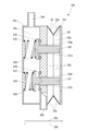
図9は、弁23、26がそれぞれ連通路20e、20fを開いている場合のダンパー装置20の正面断面図である。
タンク側室20c内のインク10cは、タンク13がタンク側室20cより高い位置に存在することによって高い圧力が加わっているので、ダンパー装置20が図9に示す状態になると、連通路20eを通ってヘッド側室20aに導入される。
ここで、連通路20eは、上述したように、連通路20eが弁23によって開かれていて連通路20fも弁26によって開かれている状態で、タンク側室20cからヘッド側室20aへのインク10cの導入量が、記録ヘッド11cによるインク10cの吐出によるヘッド側室20aのインク10cの減少量より多くなることがない断面積で形成されている。したがって、タンク側室20cからヘッド側室20aにインク10cが導入されると、ヘッド側室20aのインク10cの量は増加する。ヘッド側室20aのインク10cの量が増加すると、ヘッド側室20aの容積が増加するので、受圧板29は、蛇腹部32の伸張を伴って、矢印20gで示す方向に移動する。
受圧板29が矢印20gで示す方向に移動すると、ロッド部材30を介して受圧板29にバネ24の付勢力によって押し付けられている弁23は、矢印20gで示す方向への受圧板29の移動に伴って、矢印20gで示す方向に移動する。すなわち、弁23は、連通路20eを閉じる。
したがって、ダンパー装置20は、図9に示す状態から、再び図8に示す状態に変化する。
以上に説明したように、ダンパー装置20は、弁23、26によって開かれる連通路の断面積がヘッド側室20a内のインク10cの減少量に応じて変化する。例えば、インクジェットプリンター10が文字の印刷などのインク10cの使用量が少ない印刷を実行する場合など、ヘッド側室20a内のインク10cの減少量が少ない場合には、ダンパー装置20は、連通路20fのみを弁26によって開いて、タンク側室20cからヘッド側室20aに連通路20fを介して少量のインク10cを導入する。一方、インクジェットプリンター10がべた塗りの印刷などのインク10cの使用量が多い印刷を実行する場合など、ヘッド側室20a内のインク10cの減少量が多い場合には、ダンパー装置20は、連通路20fを弁26によって開いている状態で更に連通路20eを弁23によって開いて、タンク側室20cからヘッド側室20aに連通路20eおよび連通路20fを介して大量のインク10cを導入する。したがって、ダンパー装置20は、ヘッド側室20a内のインク10cの圧力の変動を従来より小さくすることができ、記録ヘッド11cによるインク10cの吐出の精度が安定している吐出量の範囲を従来より拡大することができる。
Oリング25は、インク10cの影響で変質し、弁23とくっ付いて離れ難くなる場合がある。同様に、Oリング28は、インク10cの影響で変質し、弁26とくっ付いて離れ難くなる場合がある。ここで、弁26は、弁23と比較して、面積が小さいので、タンク側室20cのインク10cの圧力によって受ける力が小さい。すなわち、弁26は、受圧板29からロッド部材31を介して矢印20hで示す方向に押された場合、弁23と比較して、矢印20hで示す方向に大きな力で移動させられる。したがって、弁26は、インク10cの影響で変質したOリング28とくっ付いていたとしても、弁23と比較して、Oリング28と容易に離れることができる。
ダンパー装置20は、弁26によって開閉される連通路20fが弁23に形成されているので、弁23、26が連通路20e、20fを開閉する方向、すなわち、矢印20gまたは矢印20hで示す方向に直交する方向における弁23、26の中心を一致させることができる。したがって、ダンパー装置20は、ロッド部材を介して受圧板29に力を伝達可能となる弁が受圧板29の位置の変化によって弁26のみから弁23および弁26の両方に変化した場合であっても、弁23および弁26の両方から弁26のみに変化した場合であっても、受圧板29のうちロッド部材から力を受ける部分の場所の変動を抑えることができる。その結果として、ダンパー装置20は、受圧板29の位置を滑らかに変化させることができる。
ダンパー装置20は、受圧板29の位置が変化可能であるように受圧板29を支持する蛇腹部32を備えているので、矢印20gまたは矢印20hで示す方向への受圧板29の大きな位置の変化を、蛇腹部32の大きなストロークによって容易に実現することができる。
ダンパー装置20は、後述の第3の実施の形態のように可撓性のフィルム部材自体の変形によって受圧板29の位置を変化させるのではなく、蛇腹部32の折り畳みの変形によって受圧板29の位置を変化させるので、矢印20gまたは矢印20hで示す方向に直交する方向に延在していて受圧板29の位置が変化可能であるように受圧板29を支持する後述のフィルム部材232(図17参照。)のような可撓性のフィルム部材が必要ない。したがって、ダンパー装置20は、矢印20gまたは矢印20hで示す方向に直交する方向におけるサイズを従来より小型化することができる。
なお、ダンパー装置20は、矢印20gまたは矢印20hで示す方向に直交する方向に延在していて受圧板29の位置が変化可能であるように受圧板29を支持する後述のフィルム部材232(図17参照。)のような可撓性のフィルム部材が必要ないので、矢印20gまたは矢印20hで示す方向に直交する方向における受圧板29の面積を後述の第3の実施の形態より大きくすることができる。したがって、ダンパー装置20は、弁23、26が連通路20e、20fを開くために必要な力を大気圧によって受圧板29で容易に受けることができる。
図10は、蛇腹部32の一部の断面図であって、図6に示す例とは異なる例を示す図である。
以上において説明した蛇腹部32は、図6に示す構造である。しかしながら、蛇腹部32は、図10に示す構造であっても良い。図10において、蛇腹部32は、板部32aと、板部32a同士を接続する屈曲可能な屈曲可能接続部32bとがポリエチレンなどの合成樹脂製の1つの部品として形成されている。図10において、屈曲可能接続部32bは、屈曲可能とするために板部32aと比較して薄く形成されている。
ダンパー装置20は、蛇腹部32が図10に示す構造である場合、板部32aおよび屈曲可能接続部32bが合成樹脂の一体成形によって製造されることができる。したがって、ダンパー装置20は、蛇腹部32が図10に示す構造である場合、蛇腹部32が図6に示す構造である場合と比較して、例えば製造コストを低減することができる。
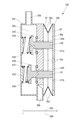
図11は、弁23、26がそれぞれ連通路20e、20fを閉じている場合のダンパー装置20の正面断面図であって、図3に示す例とは異なる例を示す図である。
ダンパー装置20は、図11に示すように、ケース21および受圧板29の間にバネ33を備えていても良い。ダンパー装置20は、図11に示す構造である場合、ヘッド側室20aのインク10cの圧力を大気圧に対して確実に負圧に維持することができる。
図12は、弁23、26がそれぞれ連通路20e、20fを閉じている場合のダンパー装置20の正面断面図であって、図3および図11に示す例とは異なる例を示す図である。
以上において説明したロッド部材31は、弁26とともにポリエチレンなどの合成樹脂製の1つの部品として形成されている。しかしながら、ロッド部材31は、図12に示すように、受圧板29とともにポリエチレンなどの合成樹脂製の1つの部品として形成されていても良い。
図13は、弁23、26がそれぞれ連通路20e、20fを閉じている場合のダンパー装置20の正面断面図であって、図3、図11および図12に示す例とは異なる例を示す図である。
以上において説明したロッド部材30は、弁23とともにポリエチレンなどの合成樹脂製の1つの部品として形成されている。しかしながら、ロッド部材30は、図13に示すように、受圧板29とともにポリエチレンなどの合成樹脂製の1つの部品として形成されていても良い。
(第2の実施の形態)
まず、本実施の形態に係るインクジェットプリンターの構成について説明する。
まず、本実施の形態に係るインクジェットプリンターの構成について説明する。
なお、本実施の形態に係るインクジェットプリンターの構成のうち第1の実施の形態に係るインクジェットプリンター10(図1参照。)の構成と同様の構成については、インクジェットプリンター10の構成と同一の符号を付して詳細な説明を省略する。
図14は、弁123、126がそれぞれ連通路120e、120fを閉じている場合の本実施の形態に係るインクジェットプリンターのダンパー装置120の正面断面図である。
本実施の形態に係るインクジェットプリンターの構成は、インクジェットプリンター10(図1参照。)がダンパー装置20(図3参照。)に代えて図14に示すダンパー装置120を備えた構成と同様である。
ダンパー装置120は、ダンパー装置20と比較して、ヘッド側室20aおよびタンク側室20cを連通する連通路120eおよび連通路120fが連通路20e(図3参照。)および連通路20f(図3参照。)に代えて形成されている。
ダンパー装置120は、ダンパー装置20と比較して、流路20bおよび流路20dが形成されたケース121と、ケース121に固定されている蓋122と、連通路120eを開閉するための弁123と、蓋122および弁123に固定されていて弁123が連通路120eを閉じる矢印20gで示す方向に弁123を付勢する付勢部材としてのバネ124と、ケース121に固定されていて弁123が連通路120eを閉じている場合にケース121および弁123の間のインク10cの漏れを防止するためのOリング125と、連通路120fを開閉するための弁126と、蓋122および弁126に固定されていて弁126が連通路120fを閉じる矢印20gで示す方向に弁126を付勢する付勢部材としてのバネ127と、ケース121に固定されていて弁126が連通路120fを閉じている場合にケース121および弁126の間のインク10cの漏れを防止するためのOリング128と、弁123および受圧板29の間に配置されて弁123および受圧板29の一方から受ける力を他方に伝達する力伝達部としてのロッド部材130と、弁126および受圧板29の間に配置されて弁126および受圧板29の一方から受ける力を他方に伝達する力伝達部としてのロッド部材131とを、ケース21(図3参照。)、蓋22(図3参照。)、弁23(図3参照。)、バネ24(図3参照。)、Oリング25(図3参照。)、弁26(図3参照。)、バネ27(図3参照。)、Oリング28(図3参照。)、ロッド部材30(図3参照。)およびロッド部材31(図3参照。)に代えて備えている。
ヘッド側室20aは、ケース121、受圧板29および蛇腹部32によって形成されている。
タンク側室20cは、ケース121および蓋122によって形成されている。
連通路120eは、ケース121およびロッド部材130によって形成されている。ここで、連通路120eの断面積は、連通路120eが弁123によって開かれていて連通路120fも弁126によって開かれている状態で、タンク側室20cからヘッド側室20aへの連通路120eおよび連通路120fを介したインク10cの導入量が、記録ヘッド11cによるインク10cの吐出によるヘッド側室20aのインク10cの減少量より多くなることがない断面積である。すなわち、連通路120eの断面積と、連通路120fの断面積との合計は、タンク側室20cからヘッド側室20aへの連通路120eおよび連通路120fを介したインク10cの導入量が、記録ヘッド11cによるインク10cの吐出によるヘッド側室20aのインク10cの減少量より多くなることがない十分に大きな面積である。
連通路120fは、ケース121およびロッド部材131によって形成されている。連通路120fの断面積は、連通路120eが弁123によって閉ざされていて連通路120fが弁126によって開かれている状態で、記録ヘッド11cによるインク10cの吐出量によっては、タンク側室20cからヘッド側室20aへの連通路120fを介したインク10cの導入量が、記録ヘッド11cによるインク10cの吐出によるヘッド側室20aのインク10cの減少量より多くなる場合がある断面積である。
ケース121は、ロッド部材130が挿入される孔121aと、ロッド部材131が挿入される孔121bとが形成されている。ケース121は、ポリエチレンなどの合成樹脂によって形成されている。
蓋122は、ポリエチレンなどの合成樹脂によって形成されている。蓋122は、ケース121に接着剤によって固定されている。
弁123は、ロッド部材130とともにポリエチレンなどの合成樹脂製の1つの部品として形成されている。
弁126は、ロッド部材131とともにポリエチレンなどの合成樹脂製の1つの部品として形成されている。
弁123、バネ124、Oリング125およびロッド部材130は、連通路120eに対して備えられている。
弁126、バネ127、Oリング128およびロッド部材131は、連通路120fに対して備えられている。
弁123、126がそれぞれ連通路120e、120fを閉じている場合、受圧板29と、ロッド部材130との距離は、受圧板29と、ロッド部材131との距離より長い。
ケース121および蛇腹部32は、接着剤によって自身に固定された図示していない可撓性のフィルム部材を介して互いに接続されている。すなわち、蛇腹部32は、このフィルム部材を介してケース121に屈曲可能に接続されている。このフィルム部材としては、蛇腹部32のフィルム部材32cの一部が代用されていても良い。
図15は、弁126が連通路120fを開いている場合のダンパー装置120の正面断面図である。
図14に示す受圧板29の位置は、ロッド部材131が弁126および受圧板29の一方から受ける力を他方に伝達可能となる時点の受圧板29の位置である。図15に示す受圧板29の位置は、ロッド部材130が弁123および受圧板29の一方から受ける力を他方に伝達可能となる時点の受圧板29の位置である。上述したように、弁123、126がそれぞれ連通路120e、120fを閉じている場合、受圧板29と、ロッド部材130との距離は、受圧板29と、ロッド部材131との距離より長い。したがって、図14に示す受圧板29の位置と、図15に示す受圧板29の位置とは異なる。
次に、ダンパー装置120の動作について説明する。
図16は、弁123、126がそれぞれ連通路120e、120fを開いている場合のダンパー装置120の正面断面図である。
ダンパー装置120は、第1の実施の形態に係るダンパー装置20と同様に、タンク側室20cからヘッド側室20aへのインク10cの導入と、ヘッド側室20aから記録ヘッド11cへのインク10cの排出との状況に応じて、図14、図15および図16に示す状態を遷移する。
以上に説明したように、ダンパー装置120は、弁123、126によって開かれる連通路の断面積がヘッド側室20a内のインク10cの減少量に応じて変化する。例えば、本実施の形態に係るインクジェットプリンターが文字の印刷などのインク10cの使用量が少ない印刷を実行する場合など、ヘッド側室20a内のインク10cの減少量が少ない場合には、ダンパー装置120は、連通路120fのみを弁126によって開いて、タンク側室20cからヘッド側室20aに連通路120fを介して少量のインク10cを導入する。一方、本実施の形態に係るインクジェットプリンターがべた塗りの印刷などのインク10cの使用量が多い印刷を実行する場合など、ヘッド側室20a内のインク10cの減少量が多い場合には、ダンパー装置120は、連通路120fを弁126によって開いている状態で更に連通路120eを弁123によって開いて、タンク側室20cからヘッド側室20aに連通路120eおよび連通路120fを介して大量のインク10cを導入する。したがって、ダンパー装置120は、ヘッド側室20a内のインク10cの圧力の変動を従来より小さくすることができ、記録ヘッド11cによるインク10cの吐出の精度が安定している吐出量の範囲を従来より拡大することができる。
(第3の実施の形態)
まず、本実施の形態に係るインクジェットプリンターの構成について説明する。
まず、本実施の形態に係るインクジェットプリンターの構成について説明する。
なお、本実施の形態に係るインクジェットプリンターの構成のうち第1の実施の形態に係るインクジェットプリンター10(図1参照。)の構成と同様の構成については、インクジェットプリンター10の構成と同一の符号を付して詳細な説明を省略する。
図17は、弁23、26がそれぞれ連通路20e、20fを閉じている場合の本実施の形態に係るインクジェットプリンターのダンパー装置220の正面断面図である。図18は、弁23、26がそれぞれ連通路20e、20fを閉じている場合のダンパー装置220の正面図である。図19は、弁23、26がそれぞれ連通路20e、20fを閉じている場合のダンパー装置220の平面図である。
本実施の形態に係るインクジェットプリンターの構成は、インクジェットプリンター10(図1参照。)がダンパー装置20(図3参照。)に代えて図17~図19に示すダンパー装置220を備えた構成と同様である。
ダンパー装置220は、ダンパー装置20と比較して、流路20bおよび流路20dが形成されたケース221と、大気圧を受けるとともに自身の位置の変化によってヘッド側室20aの容積を変化させる受圧部としての受圧板229と、受圧板229の位置が変化可能であるように受圧板229を支持する可撓性のフィルム部材232とを、ケース21(図3参照。)、受圧板29(図3参照。)および蛇腹部32(図3参照。)に代えて備えている。
ヘッド側室20aは、ケース221、受圧板229およびフィルム部材232によって形成されている。
タンク側室20cは、ケース221および蓋22によって形成されている。
ケース221は、ポリエチレンなどの合成樹脂によって形成されている。ケース221は、蓋22が接着剤によって固定されている。
受圧板229は、ポリエチレンなどの合成樹脂によって形成されている。受圧板229は、可撓性を有していない。受圧板229は、フィルム部材232に接着剤によって固定されている。
弁23、26がそれぞれ連通路20e、20fを閉じている場合、受圧板229と、ロッド部材30との距離は、受圧板229と、ロッド部材31との距離より長い。
フィルム部材232は、ケース221に接着剤によって固定されている。
図20は、弁26が連通路20fを開いている場合のダンパー装置220の正面断面図である。
図17に示す受圧板229の位置は、ロッド部材31が弁26および受圧板229の一方から受ける力を他方に伝達可能となる時点の受圧板229の位置である。図20に示す受圧板229の位置は、ロッド部材30が弁23および受圧板229の一方から受ける力を他方に伝達可能となる時点の受圧板229の位置である。上述したように、弁23、26がそれぞれ連通路20e、20fを閉じている場合、受圧板229と、ロッド部材30との距離は、受圧板229と、ロッド部材31との距離より長い。したがって、図17に示す受圧板229の位置と、図20に示す受圧板229の位置とは異なる。
次に、ダンパー装置220の製造方法について説明する。
まず、弁23にOリング28が固定された後、弁23の孔23aおよびロッド部材30の孔30aにロッド部材31が挿入されて、弁26にバネ27が固定される。
次いで、ケース221にOリング25が固定された後、ケース221の孔21aにロッド部材30が挿入されて、弁23にバネ24が固定される。
次いで、蓋22がケース221に接着剤によって固定される。したがって、バネ24は、蓋22および弁23に固定され、バネ27は、蓋22および弁26に固定される。
最後に、受圧板229が接着剤によって固定されているフィルム部材232が、ケース221に接着剤によって固定される。
次に、ダンパー装置220の動作について説明する。
図21は、弁23、26がそれぞれ連通路20e、20fを開いている場合のダンパー装置220の正面断面図である。
ダンパー装置220は、第1の実施の形態に係るダンパー装置20と同様に、タンク側室20cからヘッド側室20aへのインク10cの導入と、ヘッド側室20aから記録ヘッド11cへのインク10cの排出との状況に応じて、図17、図20および図21に示す状態を遷移する。
以上に説明したように、ダンパー装置220は、弁23、26によって開かれる連通路の断面積がヘッド側室20a内のインク10cの減少量に応じて変化する。例えば、本実施の形態に係るインクジェットプリンターが文字の印刷などのインク10cの使用量が少ない印刷を実行する場合など、ヘッド側室20a内のインク10cの減少量が少ない場合には、ダンパー装置220は、連通路20fのみを弁26によって開いて、タンク側室20cからヘッド側室20aに連通路20fを介して少量のインク10cを導入する。一方、本実施の形態に係るインクジェットプリンターがべた塗りの印刷などのインク10cの使用量が多い印刷を実行する場合など、ヘッド側室20a内のインク10cの減少量が多い場合には、ダンパー装置220は、連通路20fを弁26によって開いている状態で更に連通路20eを弁23によって開いて、タンク側室20cからヘッド側室20aに連通路20eおよび連通路20fを介して大量のインク10cを導入する。したがって、ダンパー装置220は、ヘッド側室20a内のインク10cの圧力の変動を従来より小さくすることができ、記録ヘッド11cによるインク10cの吐出の精度が安定している吐出量の範囲を従来より拡大することができる。
なお、上述した各実施の形態におけるダンパー装置は、2つの弁を備えていることによって、タンク側室20cからヘッド側室20aにインク10cを導入する動作として、インク10cの導入量が異なる2段階の動作、すなわち、少量のインク10cを導入する動作、および、大量のインク10cを導入する動作を実行するようになっている。しかしながら、ダンパー装置は、2つより多くの弁を備えることによって、タンク側室20cからヘッド側室20aにインク10cを導入する動作として、インク10cの導入量が異なる2段階より多くの段階の流量の動作を実行するようになっていても良い。
また、上述した各実施の形態におけるダンパー装置は、タンク13から供給されるインク10cを圧力の変動を抑えて記録ヘッド11cに供給するようになっている。しかしながら、ダンパー装置は、インク10c以外の液体を記録ヘッド11cに供給するようになっていても良い。例えば、ダンパー装置は、タンク13から供給される洗浄液を記録ヘッド11cに供給するようになっていても良い。ダンパー装置は、タンク13から供給される洗浄液を記録ヘッド11cに供給する場合、大量の洗浄液を導入する動作を実行すれば良い。
また、上述した各実施の形態におけるOリングは、弁が連通路を閉じている時にインク10cの流路を遮断する働きをするものである。したがって、上述した各実施の形態におけるダンパー装置は、弁が連通路を閉じている時のインク10cの流路を、Oリング以外の形状のシール材によって遮断するようになっていても良いし、Oリングなどのシール材を備えずに弁自体の圧接によって遮断するようになっていても良い。なお、シール材としては、例えばゴム製のシール材が採用されることができる。
10 インクジェットプリンター
10c インク
11c 記録ヘッド
13 タンク
20 ダンパー装置
20a ヘッド側室
20c タンク側室
20e、20f 連通路
23 弁
24 バネ(付勢部材)
26 弁
27 バネ(付勢部材)
29 受圧板(受圧部)
30、31 ロッド部材(力伝達部)
32 蛇腹部
32a 板部
32b 屈曲可能接続部
120 ダンパー装置
120e、120f 連通路
123 弁
124 バネ(付勢部材)
126 弁
127 バネ(付勢部材)
130、131 ロッド部材(力伝達部)
220 ダンパー装置
229 受圧板(受圧部)
10c インク
11c 記録ヘッド
13 タンク
20 ダンパー装置
20a ヘッド側室
20c タンク側室
20e、20f 連通路
23 弁
24 バネ(付勢部材)
26 弁
27 バネ(付勢部材)
29 受圧板(受圧部)
30、31 ロッド部材(力伝達部)
32 蛇腹部
32a 板部
32b 屈曲可能接続部
120 ダンパー装置
120e、120f 連通路
123 弁
124 バネ(付勢部材)
126 弁
127 バネ(付勢部材)
130、131 ロッド部材(力伝達部)
220 ダンパー装置
229 受圧板(受圧部)
Claims (4)
- インクを吐出する記録ヘッドと、前記インクを供給するタンクとを備えるインクジェットプリンターに備えられて、前記タンクから供給される前記インクを圧力の変動を抑えて前記記録ヘッドに供給するダンパー装置であって、
前記記録ヘッドに連通するヘッド側室と、前記タンクに連通するタンク側室と、前記ヘッド側室および前記タンク側室を連通する複数の連通路とが形成されており、
前記連通路を開閉するための弁と、前記弁が前記連通路を閉じる方向に前記弁を付勢する付勢部材と、大気圧を受けるとともに自身の位置の変化によって前記ヘッド側室の容積を変化させる受圧部と、前記弁および前記受圧部の間に配置されて前記弁および前記受圧部の一方から受ける力を他方に伝達する力伝達部とを備えており、
前記弁、前記付勢部材および前記力伝達部は、前記複数の連通路のそれぞれに対して備えられており、
前記受圧部の位置は、複数の前記力伝達部のそれぞれが前記弁および前記受圧部の一方から受ける力を他方に伝達可能となる時点毎に異なり、
前記弁によって開かれている前記連通路の断面積の合計は、前記弁の開閉状況に応じて異なることを特徴とするダンパー装置。 - 複数の前記弁の少なくとも1つは、他の前記弁によって開閉される前記連通路が形成されていることを特徴とする請求項1に記載のダンパー装置。
- 前記受圧部の位置が変化可能であるように前記受圧部を支持する蛇腹部を備えていることを特徴とする請求項1または請求項2に記載のダンパー装置。
- 前記蛇腹部は、複数の板部と、前記板部同士を接続する屈曲可能な屈曲可能接続部とを備えており、
前記板部および前記屈曲可能接続部は、合成樹脂製の1つの部品として形成されていることを特徴とする請求項3に記載のダンパー装置。
Priority Applications (1)
| Application Number | Priority Date | Filing Date | Title |
|---|---|---|---|
| CN201380057993.XA CN104781078B (zh) | 2012-11-07 | 2013-11-06 | 缓冲器装置 |
Applications Claiming Priority (2)
| Application Number | Priority Date | Filing Date | Title |
|---|---|---|---|
| JP2012245858A JP5973879B2 (ja) | 2012-11-07 | 2012-11-07 | ダンパー装置 |
| JP2012-245858 | 2012-11-07 |
Publications (1)
| Publication Number | Publication Date |
|---|---|
| WO2014073574A1 true WO2014073574A1 (ja) | 2014-05-15 |
Family
ID=50684676
Family Applications (1)
| Application Number | Title | Priority Date | Filing Date |
|---|---|---|---|
| PCT/JP2013/080025 Ceased WO2014073574A1 (ja) | 2012-11-07 | 2013-11-06 | ダンパー装置 |
Country Status (3)
| Country | Link |
|---|---|
| JP (1) | JP5973879B2 (ja) |
| CN (1) | CN104781078B (ja) |
| WO (1) | WO2014073574A1 (ja) |
Families Citing this family (4)
| Publication number | Priority date | Publication date | Assignee | Title |
|---|---|---|---|---|
| JP6077186B2 (ja) * | 2014-07-23 | 2017-02-08 | 富士フイルム株式会社 | ダンパ及びインクジェット記録装置 |
| JP6601023B2 (ja) * | 2014-10-27 | 2019-11-06 | セイコーエプソン株式会社 | 流路構造体および液体噴射装置 |
| CN107053858B (zh) * | 2017-04-24 | 2018-07-31 | 习水县西科电脑科技有限公司 | 一种打印机 |
| CN107081967B (zh) * | 2017-04-24 | 2018-06-12 | 习水县西科电脑科技有限公司 | 防漏墨盒 |
Citations (4)
| Publication number | Priority date | Publication date | Assignee | Title |
|---|---|---|---|---|
| JP2005219229A (ja) * | 2004-02-03 | 2005-08-18 | Seiko Epson Corp | 液体噴射装置 |
| JP2005306030A (ja) * | 2004-03-24 | 2005-11-04 | Seiko Epson Corp | アタッチメント、アタッチメントシステム及び液体供給装置 |
| JP2011230317A (ja) * | 2010-04-26 | 2011-11-17 | Seiko Epson Corp | 液体噴射装置 |
| JP2012045894A (ja) * | 2010-08-30 | 2012-03-08 | Canon Inc | 液体吐出装置および記録装置 |
Family Cites Families (2)
| Publication number | Priority date | Publication date | Assignee | Title |
|---|---|---|---|---|
| ATE326348T1 (de) * | 2001-10-05 | 2006-06-15 | Canon Kk | Tintenbehälter, flüssigkeitszufuhrvorrichtung und aufzeichnungsvorrichtung |
| JP5776188B2 (ja) * | 2011-01-31 | 2015-09-09 | セイコーエプソン株式会社 | 液体噴射装置 |
-
2012
- 2012-11-07 JP JP2012245858A patent/JP5973879B2/ja not_active Expired - Fee Related
-
2013
- 2013-11-06 CN CN201380057993.XA patent/CN104781078B/zh active Active
- 2013-11-06 WO PCT/JP2013/080025 patent/WO2014073574A1/ja not_active Ceased
Patent Citations (4)
| Publication number | Priority date | Publication date | Assignee | Title |
|---|---|---|---|---|
| JP2005219229A (ja) * | 2004-02-03 | 2005-08-18 | Seiko Epson Corp | 液体噴射装置 |
| JP2005306030A (ja) * | 2004-03-24 | 2005-11-04 | Seiko Epson Corp | アタッチメント、アタッチメントシステム及び液体供給装置 |
| JP2011230317A (ja) * | 2010-04-26 | 2011-11-17 | Seiko Epson Corp | 液体噴射装置 |
| JP2012045894A (ja) * | 2010-08-30 | 2012-03-08 | Canon Inc | 液体吐出装置および記録装置 |
Also Published As
| Publication number | Publication date |
|---|---|
| JP5973879B2 (ja) | 2016-08-23 |
| CN104781078B (zh) | 2016-08-17 |
| CN104781078A (zh) | 2015-07-15 |
| JP2014094462A (ja) | 2014-05-22 |
Similar Documents
| Publication | Publication Date | Title |
|---|---|---|
| JP6041732B2 (ja) | ダンパー装置 | |
| JP6009322B2 (ja) | ダンパー装置 | |
| JP5114229B2 (ja) | ダンパ及びインクジェットプリンタ | |
| CN101274529B (zh) | 墨盒、墨盒组以及墨盒确定系统 | |
| EP2322350B1 (en) | Pressure regulating valve for inkjet printer | |
| US7290861B2 (en) | Ink tank, printing head and inkjet printing apparatus | |
| JP5973879B2 (ja) | ダンパー装置 | |
| US8016396B2 (en) | Method for manufacturing liquid supply system, and liquid ejection apparatus | |
| US7325911B2 (en) | Ink cartridge and inkjet recording apparatus | |
| US6648458B2 (en) | Pinch seal providing fluid interconnects between fluid delivery system components | |
| US7690769B2 (en) | Inkjet printer head with ink-flow grooves on the wall of the common ink chamber | |
| US12151482B2 (en) | Printing apparatus and printing method | |
| JP2012218195A (ja) | 液体噴射ヘッド、及び液体噴射装置 | |
| US20150224785A1 (en) | Liquid cartridge capable of reducing force required to open air channel and liquid channel | |
| JP2011148203A (ja) | インクカートリッジ | |
| US7520599B2 (en) | Ink-jet recording apparatus | |
| CN109649008B (zh) | 液体喷出装置、其制造方法以及维护方法 | |
| CN112743987B (zh) | 流道部件、流道单元以及液体喷射装置 | |
| US8177339B2 (en) | Fluid reservoir with compliant wall | |
| JP2010054018A (ja) | バルブユニット | |
| JP2009018505A (ja) | インク吐出装置、画像形成装置 | |
| US7581813B2 (en) | Ink-jet recording apparatus | |
| US20180311959A1 (en) | Printheads | |
| JP2015174417A (ja) | 液体吐出ヘッド及び液体吐出装置 |
Legal Events
| Date | Code | Title | Description |
|---|---|---|---|
| 121 | Ep: the epo has been informed by wipo that ep was designated in this application |
Ref document number: 13853337 Country of ref document: EP Kind code of ref document: A1 |
|
| NENP | Non-entry into the national phase |
Ref country code: DE |
|
| 122 | Ep: pct application non-entry in european phase |
Ref document number: 13853337 Country of ref document: EP Kind code of ref document: A1 |