WO2014073480A1 - 切削工具の刃先構造並びに該構造を用いた切削インサートおよび切削工具 - Google Patents
切削工具の刃先構造並びに該構造を用いた切削インサートおよび切削工具 Download PDFInfo
- Publication number
- WO2014073480A1 WO2014073480A1 PCT/JP2013/079713 JP2013079713W WO2014073480A1 WO 2014073480 A1 WO2014073480 A1 WO 2014073480A1 JP 2013079713 W JP2013079713 W JP 2013079713W WO 2014073480 A1 WO2014073480 A1 WO 2014073480A1
- Authority
- WO
- WIPO (PCT)
- Prior art keywords
- cutting edge
- wall surface
- cutting
- ridge line
- edge structure
- Prior art date
- Legal status (The legal status is an assumption and is not a legal conclusion. Google has not performed a legal analysis and makes no representation as to the accuracy of the status listed.)
- Ceased
Links
Images






Classifications
-
- B—PERFORMING OPERATIONS; TRANSPORTING
- B23—MACHINE TOOLS; METAL-WORKING NOT OTHERWISE PROVIDED FOR
- B23B—TURNING; BORING
- B23B51/00—Tools for drilling machines
- B23B51/02—Twist drills
-
- B—PERFORMING OPERATIONS; TRANSPORTING
- B23—MACHINE TOOLS; METAL-WORKING NOT OTHERWISE PROVIDED FOR
- B23B—TURNING; BORING
- B23B27/00—Tools for turning or boring machines; Tools of a similar kind in general; Accessories therefor
- B23B27/14—Cutting tools of which the bits or tips or cutting inserts are of special material
- B23B27/141—Specially shaped plate-like cutting inserts, i.e. length greater or equal to width, width greater than or equal to thickness
-
- B—PERFORMING OPERATIONS; TRANSPORTING
- B23—MACHINE TOOLS; METAL-WORKING NOT OTHERWISE PROVIDED FOR
- B23B—TURNING; BORING
- B23B2200/00—Details of cutting inserts
- B23B2200/12—Side or flank surfaces
- B23B2200/125—Side or flank surfaces discontinuous
-
- B—PERFORMING OPERATIONS; TRANSPORTING
- B23—MACHINE TOOLS; METAL-WORKING NOT OTHERWISE PROVIDED FOR
- B23B—TURNING; BORING
- B23B2200/00—Details of cutting inserts
- B23B2200/12—Side or flank surfaces
- B23B2200/128—Side or flank surfaces with one or more grooves
-
- B—PERFORMING OPERATIONS; TRANSPORTING
- B23—MACHINE TOOLS; METAL-WORKING NOT OTHERWISE PROVIDED FOR
- B23B—TURNING; BORING
- B23B2200/00—Details of cutting inserts
- B23B2200/20—Top or side views of the cutting edge
- B23B2200/204—Top or side views of the cutting edge with discontinuous cutting edge
-
- B—PERFORMING OPERATIONS; TRANSPORTING
- B23—MACHINE TOOLS; METAL-WORKING NOT OTHERWISE PROVIDED FOR
- B23B—TURNING; BORING
- B23B2251/00—Details of tools for drilling machines
- B23B2251/50—Drilling tools comprising cutting inserts
Definitions
- the present invention relates to a cutting edge structure of a tool for cutting and a cutting insert and a cutting tool using the structure, and more particularly to a structure for smoothing outflow of chips.
- Patent Document 1 discloses a cutting insert used for a milling tool
- Patent Document 2 discloses a cutting tool used for a blade-exchangeable drill. An insert is disclosed. And in these patent documents, the structure which the cutting edge provided in both sides across the corner part of the cutting insert cuts simultaneously, and the structure which intends discharging
- an object of the present invention is to provide a structure that suppresses a collision between chips flowing out in two different directions from the vicinity of a corner portion.
- the present invention includes a polygonal end face (20) and a side face (40) connected to the end face (20), and an intersecting ridge line part () between the end face (20) and the side face (40) ( 50), at least the first and second ridgelines sandwiching the bent portion (51) formed by one vertex of the polygon act as the first and second cutting edges (53, 54), respectively.
- a cutting edge structure of a cutting tool including a part, A first portion (53a1) formed on at least a first flank (41) connected to the first cutting edge (53), and the first cutting edge (53) close to the bent portion (51); A recess (60) that divides into a second part (53a2) far from the bent part (51);
- the recess (60) includes a first inner wall surface (61) including a ridge line (61a) connected to the first part (53a1) and a ridge line (62a) connected to the second part (53a2).
- the present invention also resides in a cutting insert and a cutting tool provided with the above-mentioned cutting edge structure.
- the concave portion (60) having a triangular shape as viewed in plan is formed in the portion of the first cutting edge (53) in the vicinity of the bent portion (51), and the first cutting edge (53 ) Is divided into a first part (53a1) close to the bent part (51) and a second part (53a2) far from the bent part (51).
- the chips flowing out from the cutting edge (53) are subdivided and the flow of chips from the first part (53a1) is weakened, so the chips flowing out from the second cutting edge (52) No longer obstruct the flow of Further, the cross ridge line (62a) between the inner wall surface (62) of the recess (60) and the rake face of the end face (20) and connected to the second portion (53a2) also acts as a cutting edge. The strength of the flow of chips flowing out from the second portion (53a2) is greater than the strength of the flow of chips flowing out from the second portion (53a2).
- the chip flow generated from the second portion (53a2) is forcibly bent by the chip flow generated from the intersecting ridge line (62a) and integrated therewith, and flows in the same direction. As described above, the collision state of the chip flow generated from the pair of cutting edges (53, 54) sandwiching the bent portion is suppressed.
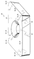
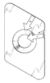
- FIG. 1 is a perspective view of a cutting insert according to a first embodiment of the present invention.
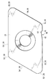
- FIG. 2 is a plan view of the cutting insert according to the first embodiment of the present invention.
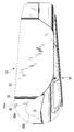
- FIG. 3 is a side view of the cutting insert according to the first embodiment of the present invention as seen from the side surface where the recess is formed.
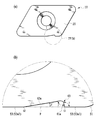
- FIG. 4A is a schematic plan view of the cutting insert of the first embodiment, and FIG. 4B is a portion IV (b) in FIG. 4A for explaining the recess according to the first embodiment.
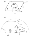
- FIG. FIG. 5A is a schematic plan view of the cutting insert of the first embodiment, and FIG. 5B is a portion V (b) in FIG. 5A for explaining the chip discharge direction in the vicinity of the corner portion.
- FIG. 6A is a schematic plan view of the cutting insert of the first embodiment
- FIG. 6B is a portion VI (b) in FIG. 6A for explaining the outflow direction of chips in the vicinity of the recess.
- FIG. 7 is a schematic diagram for explaining a chip discharge direction as the entire cutting insert according to the first embodiment.
- FIG. 8 is an explanatory diagram for explaining the honing width and the imaginary line length of the cutting insert according to the first embodiment.
- FIG. 9 is a perspective view of a cutting insert according to the second embodiment of the present invention.
- FIG. 10 is a plan view of a cutting insert according to the second embodiment of the present invention.
- FIG. 11 is a side view of a cutting insert according to the second embodiment of the present invention.
- FIG. 12 is a perspective view of a drill using the cutting insert of the second embodiment.
- FIG. 13 is a front view of a drill using the cutting insert of the second embodiment.
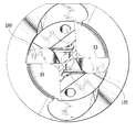
- FIG. 14 is a tip view of a drill using the cutting insert of the second embodiment.
- the gist of the present invention is to provide a recess having a special shape in the vicinity of the corner portion of the bending edge, so that chips flowing out from the cutting edge on the side where the recess is provided are subdivided, and the outflow direction is a preferred direction. It is to adopt a structure that can be changed to.
- (First embodiment) 1 to 3 are views of the cutting insert according to the first embodiment of the present invention as seen from each direction.
- the outer shape of the upper surface 20 that is the first end surface and the lower surface 30 that is the second end surface of the cutting insert 10 of the present embodiment is a substantially parallelogram having two long sides and two short sides, Cutting edges are formed at the intersection ridges 50 between the respective surfaces and the side surfaces 40.
- the side surface 40 intersects the upper surface 20 and the lower surface 30 at 90 °, and the cutting insert 10 is configured as a so-called negative type having a clearance angle of 0 °.
- a screw hole 70 penetrating from the upper surface 20 to the lower surface 30 is formed, and the cutting insert 10 is fixed to a tool body (not shown) by a screw inserted through the screw hole 70.
- the phrase “viewed from the direction facing the upper surface” means observing the upper surface 20 from a direction perpendicular to the seating surface that is a contact surface with the tool body.
- the above wording means a so-called planar view.
- the phrase “viewed from the direction facing the lower surface” means that the lower surface 30 is observed from a direction perpendicular to the seating surface that is a contact surface with the tool body.
- the upper surface 20 is a flat surface as in this embodiment, the above wording means a so-called bottom view.
- the phrase “viewed from the direction facing the side surface” means to observe from a direction perpendicular to the side surface.
- a side surface having a clearance angle it means viewing from a direction in which the area of the surface to be observed is parallel to the seating surface and maximizes.
- the crossed ridge line portion 50 having a parallelogram shape includes two obtuse corner portions 51 and 51 ′, two acute angle corner portions 52 and 52 ′, two ridge lines that are long sides of the parallelogram, and a short side. And two ridgelines.
- Each of the two ridge lines that are long sides includes a portion that becomes a first cutting edge (hereinafter referred to as long cutting edges 53 and 53 ′ in the present embodiment), and each of the two ridge lines that are short sides is a second cutting edge. This includes a portion (hereinafter referred to as a short cutting edge 54, 54 'in the present embodiment).
- the corner portion conforms to the definition of JIS B 0170 “a relatively small range of cutting edge portions that connect one cutting edge to another cutting edge”.
- the terms “obtuse angle” and “acute angle” for specifying the shape of the corner portion are defined with respect to an angle formed by ridge lines extending at both ends of the corner portion when viewed in plan.
- the “cutting edge” means a ridge line portion in a cutting edge structure that participates in (or can participate in) the cutting of the workpiece.
- a recess 60 is formed in the vicinity of the obtuse corner part 51, and the long cutting edge 53 is close to the obtuse corner part 51 across the recess 60. It is divided into a portion 53a1 and a cutting edge portion 53a2 far from the obtuse corner portion 51.
- the concave portion 60 has a substantially triangular shape when viewed from the direction facing the upper surface 20. As will be described later, the fragmentation of the chips flowing out from the long cutting edge 53 and the control of the direction in which the chips flow out. I do.
- the recess 60 includes a first inner wall surface 61 that is an inner wall surface located on the side closer to the obtuse corner portion 51, a second inner wall surface 62 that is an inner wall surface located farther from the obtuse corner portion 51, and a first inner wall surface. 61 and a connecting surface 63 that connects the second inner wall surface 62 to each other.
- the connecting surface 63 is not limited in shape, and may be formed by a single curved surface as shown in FIGS. 2, 4A and 4B, or may be formed by a single plane. It may be a thing. Alternatively, a plurality of curved surfaces, a plurality of planes, or a combination of a plurality of curved surfaces and a plane may be used.
- the top surface 20 and the first inner portion are viewed from the direction facing the top surface 20.
- the ridge line 61a with the wall surface 61 intersects the cutting edge portion 53a1 of the long cutting edge 53 at an angle ⁇ of about 100 °.
- This angle is appropriately set within a range in which the chips are sufficiently subdivided and sufficient fracture resistance is secured at the intersection between the recess 60 and the cutting edge portion 53a1.
- a standard for this angle ⁇ is about 100 ° ⁇ 15 °.
- the ridge line 62 a between the upper surface 20 and the second inner wall surface 62 is significantly longer than the ridge line 61 a of the first inner wall surface 61 and is set to be three times or more. Therefore, a virtual line P formed by connecting the connection portion Q1 between the first inner wall surface 61 and the cutting edge portion 53a1 and the connection portion Q2 between the second inner wall surface 62 and the cutting edge portion 53a2 (FIG. 4B). ), The angle ⁇ formed by the ridge line 62a between the upper surface 20 and the second inner wall surface 62 with respect to the virtual line P is a relatively small value. Further, the position of the connecting surface 63 is also largely shifted to the connection portion Q1 side.
- the angle ⁇ is preferably as small as possible within a range in which chip fragmentation is achieved. Therefore, the length of the ridge line 62a of the second inner wall surface 62 is not less than five times the length of the ridge line 61a of the first inner wall surface 61. It is preferable.
- the crossing angle between the ridgeline 62a of the second inner wall surface 62, which is the angle ⁇ or the outer angle thereof, and the long cutting edge 53 is by appropriately regulating the flow direction of chips generated by the long cutting edge 53, It is preferable that the value be set to a value that can prevent a severe collision of chips generated in the vicinity of the corner portion (the obtuse corner portion 51 in this embodiment), which is the subject of the present invention.
- the direction perpendicular to the ridge line 62 a of the second inner wall surface 62 is a direction away from the obtuse corner portion 51 when the direction perpendicular to the long cutting edge 53 is taken as a reference.
- This direction coincides with the flow direction of chips generated at the ridge line 62a.
- the length of the ridge line 62a is determined in relation to the cutting depth assumed when the cutting insert 10 is used. That is, the length of the cutting edge portion 53a2 that is a cutting edge portion that is connected to the recess 60 at a position far from the obtuse corner portion 51 and that is involved in cutting when the maximum possible rightward cutting in the drawing is performed.
- the ridgeline 62a is set to be longer than that.
- the ridge line 62 a is formed so as to act as a cutting edge when cutting is performed with a cutting amount exceeding the recess 60.
- the length is set so that the width of the chip generated at the ridgeline 62a is larger than the width of the chip generated at the adjacent cutting edge portion 53a2. If another expression is used, when the cutting insert 10 of the present embodiment is used within a range where the length of the cutting edge portion 53a2 is smaller than the length of the ridgeline 62a, the effect is maximized.
- the side surface and the first inner wall surface 61 As shown in FIG. 3, when viewed from a direction facing one side surface (hereinafter also referred to as the first flank 41) connected to the long cutting edge 53, the side surface and the first inner wall surface 61
- the ridge line 61b is inclined, and the end portion 61b2 of the ridge line 61b on the lower surface 30 side is located closer to the obtuse corner portion 51 than the end portion 61b1 of the ridge line 61b on the upper surface 20 side.
- the ridge line 61b When the ridge line 61b is observed in a side view with the upper surface 20 facing upward, the ridge line 61b becomes closer to the obtuse corner portion 51 as the distance from the end portion 61b1 increases. So it extends to the right. With such a configuration, when the cutting insert 10 is used so that the upper surface 20 becomes a rake face, a sufficient gap can be secured between the first flank 41 and the work material. Excessive contact can be
- the cutting insert 10 of the present embodiment By forming the recess 60 in the vicinity of the obtuse corner portion 51a, the long cutting edge 53 is divided, and a cutting edge portion 53a1 and a cutting edge portion 53a2 sandwiching the recess 60 are formed.
- the cutting edge portion 53a2 refers not only to the entire ridge line from the connection portion to the concave portion 60 to the acute corner portion 52, but only to a cutting participating portion that acts as a cutting edge during cutting as described above.
- FIG. 5 (b) When the cutting insert 10 starts cutting with the obtuse corner portion 51 as the distal end side, as shown in FIG. 5 (b) in which a broken line portion in the top view (FIG. 5 (a)) of the cutting insert 10 is enlarged, Chips flow out from the cutting edge portion 53a1 and the short cutting edge 54a of the blade 53 in directions orthogonal to each other.
- the arrow A in FIG. 5 (b) indicates the flow direction of chips generated from the cutting edge portion 53a1 (corresponding to the flow direction of chips generated from the long cutting edge 53 when there is no recess 60), and the arrow B is short. An outflow direction of chips generated from the cutting edge 54 is shown.
- the width of the chip flowing out from the cutting edge portion 53a1 is extremely smaller than the width of the chip flowing out from the short cutting edge 54, the weight per unit length of the chip is also from the cutting edge portion 53a1.
- the one that flows out is lighter. Therefore, although the outflow direction of the two chips intersects at a deep angle, the outflow direction of the chip flowing out from the cutting edge portion 53a1 is forcibly bent by the outflow from the short cutting edge 54a, resulting in a short cut. It flows in the direction of arrow B which is the same as the flow direction of chips flowing out from the blade 54a.
- the flow of one chip (here, the flow from the short cutting edge 54a) is obtained by intentionally changing the strength of the chip flow. Can be prevented from obstructing the flow of the other chip (here, the flow from the cutting edge portion 53a1), and as a result, the chip flows smoothly as a whole.
- the ridgeline 62a and the cutting edge portion 53a2 also act as cutting edges, and as shown in FIG. 6 (b) in which the broken line portion in the top view (FIG. 6 (a)) of the cutting insert 10 is enlarged, Chips are generated from each. Also at this time, since the ridge line 62a is longer than the cutting edge portion 53a2, the same phenomenon as described above occurs, and the outflow direction of the chips flowing out from the cutting edge portion 53a2 (arrow D) flows out from the ridge line 62a. It will be forced to bend in the direction of chip flow (arrow C).
- the ridgeline 62a is inclined by an angle ⁇ with respect to the virtual line P as described above with reference to FIG. Therefore, as shown in FIG. 7, the angle of intersection between the arrow B (the chip outflow direction from the short cutting edge 54) and the arrow C (the chip outflow direction from the ridge line 62a) is an arrow B and an arrow A ( As indicated by the phantom line, the crossing angle is smaller than the crossing angle of the outflow direction from the long cutting edge 53a when the recess 60 is not present.
- the collision state of chips is relieved greatly, and the effect that chips will flow more smoothly than before is obtained.
- the recess 60 provided in the cutting insert according to the present embodiment is different from the nick that is conventionally employed to simply divide the cutting edge to generate fine chips.
- the angle ⁇ is expressed by the following formula tan ⁇ > H / L (Formula 1) It will be of a size that meets the requirements.
- the honing width H is the length from the position of the honing start to the position of the honing end when viewed from the direction facing the upper surface 20.
- the angle ⁇ formed by the cutting edge portion 53a1 and the ridge line 61b is 60 ° or more and 80 °.
- the gap between the work material and the cutting insert 10 when the cutting insert 10 is attached to the tool body can be sufficiently secured, and at the same time, the intersection of the cutting edge portion 53a1 and the first inner wall surface 61.
- Improves fracture resistance in other words, in terms of such a view, a position where only the ridge line 61b of the first inner wall surface 61 can be seen and other parts of the first inner wall surface 61 cannot be seen among various views of viewing the side surface. And view from an angle.
- the angle ⁇ formed by the ridge line 61a of the first inner wall surface 61 and the ridge line 62a of the second inner wall surface 62 when viewed from the direction facing the upper surface 20 is used. Is from 50 ° to 120 °, more preferably from 80 ° to 100 °. When the angle ⁇ is within this range, the intersection between the concave portion 60 and the long cutting edge 53 is not too sharp and it is difficult for a sudden defect to occur.
- the chips are preferable.
- the length of the cutting edge portion 53a1 is shorter than the ridge line 61a of the first inner wall surface 61, chips are more easily subdivided.
- the same recessed part can also be provided in the long cutting edge 53 ', for example. That is, when viewed from the direction facing the upper surface, the cutting insert 10 is rotated 180 degrees with respect to the axis of the screw hole 70 by providing a recess at a rotationally symmetrical position with respect to the diagonal line connecting the acute corner portions 52 and 52 ′. It is also possible to make it usable.
- FIGS. 9 to 11 are views of the cutting insert according to the second embodiment of the present invention as seen from each direction.
- 12 to 14 are views showing a state when the cutting insert of the second embodiment is attached to the tool body of the drill.
- parts having the same functions as those in the first embodiment are denoted by the same reference numerals as those used in FIGS.
- the cutting insert 100 of this embodiment is a cutting insert for a drill, and particularly a cutting insert for a two-blade drill as shown in FIGS.
- the cutting insert 100 is configured such that the same shape as those figures appears even if the front and back are reversed so that the lower surface on the back side of the upper surface 20 shown in FIGS. 9 and 10 becomes the upper surface. That is, the cutting insert 100 of this embodiment is 180 ° rotationally symmetric with respect to a line R of a rotation axis (FIG. 10) that is parallel to the seating surface 21 formed on the upper surface 20 and passes through the center of the cutting insert 100. It has a (two-fold symmetry) shape. To explain this in another intuitive expression, the cutting insert 100 has a two-fold symmetrical shape around an axis of rotation parallel to the seating surface 21 and passing through the center of the cutting insert 100.
- the cutting insert 100 of the present embodiment has a rotationally symmetric shape
- the shape on the upper surface 20 side will be mainly described, and the description on the lower surface 30 side which is a similar shape will be described. Omitted.
- the cutting edges are a long cutting edge 53 and a short cutting edge 54 extending on both sides across one obtuse corner portion 51 formed on the upper surface 20, and the other crossing ridge line portion between the upper surface 20 and the side surface 40 is cut. Does not act as a blade.
- FIGS. 12 (a) and 13 (a) FIGS. 12 (a) and 13 (b), which are enlarged views of broken lines in the respective drawings.
- the long cutting edge 53 acts as an outer peripheral edge
- the short cutting edge 54 acts as a central edge.
- the recess 60 is formed on the side surface to which the short cutting edge 54 is connected (that is, in this embodiment, the short cutting edge 54 is the first cutting edge).
- a recess 80 is formed on the upper surface 20, and the recess 80 is formed in a position and shape that includes the first inner wall surface 61 of the recess 60 inside when viewed from the direction facing the upper surface 20. That is, the depression 80 is formed at a position where the ridge line of the depression 60 passes through the inside of the depression 80.
- the angle ⁇ formed by the above-described cutting edge 53 a 1 and the ridge line 61 a becomes larger than the case where there is no recess 80.
- the intersecting ridge line portion 62a between the second inner wall surface 62 and the upper surface 20 is formed in a curved shape that is convex toward the upper surface side. Yes.
- the intersecting ridge line portion 62a also acts as a center blade.
- the end-expanding space is attached to the tip of the tool.
- the angle ⁇ , the angle ⁇ (shown in FIG. 10), and the angle ⁇ (shown in FIG. 11) are set in the same manner as the preferred form in the first embodiment. preferable.
- the present invention is not limited only to the above-described embodiment, and the form can be changed as appropriate without departing from the technical idea thereof. That is, the cutting insert can take various shapes, and in accordance with the shape, a concave portion capable of obtaining the effects of the present invention can be formed on an appropriate ridge line or cutting edge. That is, even when the cutting insert 10 having a shape that is twice symmetrical with respect to the axis of the screw hole 70 that penetrates the upper surface and the lower surface that are the end surfaces in the first embodiment, and the front and back sides in the second embodiment are reversed.
- the cutting insert 100 in which the same shape appears is illustrated as an example, and it has been described that a recess can be provided at each rotationally symmetric position.
- each of the two ridge lines sandwiching the corner portion (bending portion) has a shape that is n times rotationally symmetric with respect to the other rotation axes.
- the cutting insert includes a portion that acts as a cutting edge, the concave portion can be provided at an appropriate position in accordance with the cutting insert.
- the shape of the connecting surface of the recess may be a plane, a combination of a plurality of curved surfaces, a combination of a plurality of planes, or a combination of a curved surface and a plane. Since the gist of the present invention is that the ridge line of the second inner wall surface is significantly longer than the ridge line of the first inner wall surface when viewed from the direction facing the upper surface and the angle ⁇ described above is small, the shape of the connecting surface A certain effect is exhibited no matter what. However, it is not preferable that the connecting surface is extremely large among the inner wall surfaces constituting the recess, the area of the second inner wall surface is larger than any other inner wall surface, and the connecting surface is formed with a minimum size. Most preferably.
- the connecting surface When the connecting surface is smoothly connected to the first inner wall surface and the second inner wall surface, it becomes difficult to determine the boundary between the connecting surface and each inner wall surface, and the end position of the ridge line of each inner wall surface is difficult to understand.
- the center of the connecting surface may be handled as the end portion of each inner wall surface.
Landscapes
- Engineering & Computer Science (AREA)
- Mechanical Engineering (AREA)
- Milling Processes (AREA)
- Drilling Tools (AREA)
- Cutting Tools, Boring Holders, And Turrets (AREA)
Abstract
切削コーナから異なる方向に延びる切れ刃から流出する切りくず同士が激しく衝突することを避けるために、切りくずの流出方向を制御することができる切削工具の先端構造を提供する。一方の切れ刃(53)の、コーナ部(51)の近傍の部位に、第1内壁面(61)と第2内壁面(62)とを有する凹部(60)を形成する。ここで、上面(20)に対向する方向から見たときの第2内壁面(62)の稜線(62a)の長さが、同方向から見たときの第1内壁面(61)の稜線(61a)よりも長く、切れ刃(53)と第2内壁面(62)の稜線(62a)とがなす角度βを適切に設定する。
Description
本発明は、切削加工のための工具の刃先構造並びに該構造を用いた切削インサートおよび切削工具に関し、特に切りくずの流出状態を円滑にするための構造に関する。
従来、回転切削工具の分野においては様々な形状の切削インサートが用いられており、例えば特許文献1にはフライス工具に用いられる切削インサートが、また特許文献2には刃先交換式ドリルに用いられる切削インサートが開示されている。そして、これらの特許文献においては、切削インサートのコーナ部を挟んで両側に設けられた切れ刃が同時に切削を行う構成、および、切りくずを円滑に排出することを企図した構成が記載されている。
しかしながら、これらの特許文献は、コーナ部を挟んだ両側の切れ刃が同時に切削を行った場合に発生する切りくずの流れについては何ら考慮されていない。切りくずは切れ刃にほぼ直角の方向に流出する傾向があるので、切れ刃がなす角度が大きくなるほど各切れ刃から流出する切りくずの流れが交差する角度が大きくなり、それぞれから流出した切りくず同士は激しく衝突する。このように切りくずが激しく衝突すると、それぞれの切りくずの流れの向きが大きく変わることで、切りくずが円滑に排出されなくなったり、切削インサートや工具本体を傷つけて損傷させたりすることが頻発する。本発明者が鋭意検討したところ、この切りくず同士の衝突は、コーナ部から比較的遠い切れ刃の箇所から流出する切りくず同士よりも、コーナ部付近の切れ刃の箇所から流出する切りくず同士において顕著であって、上記の問題の主要な部分を占めるという知見を得た。
本発明は上記の課題に鑑み、コーナ部近傍から異なる二つの方向へ流出する切りくず同士の衝突を抑制する構造を提供することを目的とする。
そのために、本発明は、多角形の端面(20)と、該端面(20)に接続する側面(40)と、を備え、前記端面(20)と前記側面(40)との交差稜線部(50)のうち、少なくとも、前記多角形の一頂点部分がなす屈曲部(51)を挟む第1および第2の稜線が、それぞれ、第1および第2の切れ刃(53,54)として作用する部分を含んでいる切削工具の刃先構造であって、
少なくとも前記第1の切れ刃(53)に接続する第1逃げ面(41)に形成され、前記第1の切れ刃(53)を前記屈曲部(51)に近い第1の部分(53a1)および前記屈曲部(51)から遠い第2の部分(53a2)に分割する凹部(60)を備え、
該凹部(60)は、前記第1の部分(53a1)に接続する稜線(61a)を含む第1内壁面(61)と、前記第2の部分(53a2)に接続する稜線(62a)を含む第2内壁面(62)とを備え、
前記端面(20)に対向する方向から見たとき、前記第2内壁面(62)が含む前記稜線(62a)が、前記第1内壁面(61)が含む前記稜線(61a)よりも長くなっている刃先構造を提供する。
少なくとも前記第1の切れ刃(53)に接続する第1逃げ面(41)に形成され、前記第1の切れ刃(53)を前記屈曲部(51)に近い第1の部分(53a1)および前記屈曲部(51)から遠い第2の部分(53a2)に分割する凹部(60)を備え、
該凹部(60)は、前記第1の部分(53a1)に接続する稜線(61a)を含む第1内壁面(61)と、前記第2の部分(53a2)に接続する稜線(62a)を含む第2内壁面(62)とを備え、
前記端面(20)に対向する方向から見たとき、前記第2内壁面(62)が含む前記稜線(62a)が、前記第1内壁面(61)が含む前記稜線(61a)よりも長くなっている刃先構造を提供する。
また、本発明は、上記刃先構造を備えた切削インサートおよび切削工具にも存する。
本発明によると、屈曲部(51)付近の第1の切れ刃(53)の部分に、平面視したときの基本形状が三角形状の凹部(60)が形成され、第1の切れ刃(53)は屈曲部(51)に近い第1の部分(53a1)および屈曲部(51)から遠い第2の部分(53a2)に分割される。これにより、その切れ刃(53)から流出する切りくずが細分化されて、第1の部分(53a1)からの切りくずの流れが弱まるので、第2の切れ刃(52)から流出する切りくずの流れを阻害しなくなる。さらに、凹部(60)の内壁面(62)と端面(20)のすくい面との交差稜線であって且つ第2の部分(53a2)につながる交差稜線(62a)も切れ刃として作用し、そこから流出する切りくずの流れの強さは第2の部分(53a2)から流出する切りくずの流れの強さよりも大となる。そのため、第2の部分(53a2)から生じる切りくずの流れは上記交差稜線(62a)から生じる切りくずの流れによって強制的に曲げられてこれと一体化し、同じ方向に流れるようになる。以上により、屈曲部を挟んだ一対の切れ刃(53,54)から生じる切りくずの流れの衝突状態が緩和抑制される。
以下、本発明のいくつかの実施形態を、図面を用いて説明する。本発明の要旨は、屈曲する切れ刃のコーナ部近傍に特殊な形状の凹部を設けることで、凹部が設けられた側の切れ刃から流出する切りくずを細分化し、且つその流出方向を好ましい方向に変化させることができる構造を採用することである。
(第1の実施形態)
図1~図3は、本発明の第1の実施形態の切削インサートを各方向から見た図である。本実施形態の切削インサート10の第1の端面である上面20および第2の端面である下面30の外郭形状は、二つの長辺と二つの短辺とを有するほぼ平行四辺形であって、それぞれの面と側面40との交差稜線部50に切れ刃が形成される。側面40は上面20および下面30と90°で交差しており、切削インサート10は逃げ角が0°のいわゆるネガティブタイプのものとして構成されている。上面20から下面30にかけて貫通するネジ穴70が形成されており、ネジ穴70に挿通されるネジによって切削インサート10が工具本体(不図示)に固定される。
図1~図3は、本発明の第1の実施形態の切削インサートを各方向から見た図である。本実施形態の切削インサート10の第1の端面である上面20および第2の端面である下面30の外郭形状は、二つの長辺と二つの短辺とを有するほぼ平行四辺形であって、それぞれの面と側面40との交差稜線部50に切れ刃が形成される。側面40は上面20および下面30と90°で交差しており、切削インサート10は逃げ角が0°のいわゆるネガティブタイプのものとして構成されている。上面20から下面30にかけて貫通するネジ穴70が形成されており、ネジ穴70に挿通されるネジによって切削インサート10が工具本体(不図示)に固定される。
なお、以下の説明において、「上面に対向する方向から見る」という文言は、工具本体との接触面である着座面に垂直な方向から上面20を観察することを意味する。本実施形態のように下面30が平坦な面の場合、上記の文言はいわゆる平面視を意味する。一方、「下面に対向する方向から見る」という文言は、工具本体との接触面である着座面に垂直な方向から下面30を観察することを意味する。本実施形態のように上面20が平坦な面の場合、上記の文言はいわゆる下面視を意味する。さらに、「側面に対向する方向から見る」という文言は、その側面に垂直な方向から観察することを意味する。ただし、逃げ角を有する側面の場合は、着座面に平行且つ観察するその面の面積が極大となる方向から見ることを意味する。
平行四辺形状である交差稜線部50は、二つの鈍角コーナ部51,51’と、二つの鋭角コーナ部52,52’と、上記平行四辺形の長辺となる二つの稜線と、同じく短辺となる二つの稜線と、を含む。長辺となる二つの稜線のそれぞれは第1切れ刃(以下、本実施形態において長切れ刃53,53’という)となる部分を含み、短辺となる二つの稜線のそれぞれは第2切れ刃(以下、本実施形態において短切れ刃54,54’という)となる部分を含んでいる。なお、コーナ部については、JIS B 0170の定義である「一つの切れ刃と他の切れ刃とがつながるかどの、比較的小範囲の切れ刃部分」に準拠するものであって、本実施形態に即して言えば「切れ刃同士を結ぶ湾曲した切れ刃部分であって、その極く小さい部分」を意味する。また、コーナ部の形状を特定するための「鈍角」や「鋭角」の文言は、平面視したときにおいてコーナ部の両端に延びる稜線同士のなす角度に関して定義される。さらに、「切れ刃」とは、被削物の切削に関与する(もしくは関与し得る)刃先構造における稜線部分を意味する。
一方の長切れ刃53およびこれにつながる上面20および40には、鈍角コーナ部51の近傍に凹部60が形成され、この凹部60を挟んで、長切れ刃53は鈍角コーナ部51に近い切れ刃部分53a1と鈍角コーナ部51から遠い切れ刃部分53a2とに分割されている。この凹部60は、上面20に対向する方向から見たときに略三角形状をなしており、後述するように、長切れ刃53から流出する切りくずの細分化と、切りくずの流出方向の制御を行う。
凹部60は、鈍角コーナ部51に近い側に位置する内壁面である第1内壁面61と、鈍角コーナ部51から遠い側に位置する内壁面である第2内壁面62と、第1内壁面61と第2内壁面62とを接続するつなぎ面63とを備える。つなぎ面63については形状的な制限はなく、図2、図4(a)および(b)に示すように一つの曲面で形成されているものでもよいし、あるいは一つの平面で形成されているものでもよい。または、複数の曲面、複数の平面、または複数の曲面と平面との組み合わせで構成されているものでもよい。
本実施形態の切削インサート10の上面図(図4(a))における破線部分を拡大した図4(b)に示すように、上面20に対向する方向から見たとき、上面20と第1内壁面61との稜線61aは長切れ刃53の切れ刃部分53a1に対して100°前後の角度αで交差する。この角度は、切りくずが充分に細分化され、なおかつ凹部60と切れ刃部分53a1との交差部に充分な耐欠損性が確保される範囲内で適宜設定される。この角度αの目安としては、100°±15°程度である。
上面20と第2内壁面62との稜線62aは、第1内壁面61の稜線61aと比べて有意に長く、3倍以上に設定されている。そのため、第1内壁面61と切れ刃部分53a1との接続部Q1と、第2内壁面62と切れ刃部分53a2との接続部Q2とを結んで形成される仮想線P(図4(b)の破線)を想定したとき、上面20と第2内壁面62との稜線62aがこの仮想線Pに対してなす角度βは相対的に小さな値となる。また、つなぎ面63の位置も接続部Q1側に大きく寄った位置にある。この角度βは切りくずの細分化が達成される範囲内で小さいほど好ましく、そのため第2内壁面62の稜線62aの長さは第1内壁面61の稜線61aの長さの5倍以上であることが好ましい。その一方、角度β、ないしはその外角である第2内壁面62の稜線62aと長切れ刃53との交差角度は、長切れ刃53が発生する切りくずの流出方向を適切に規制することで、この発明の課題となっているコーナ部(本実施形態では鈍角コーナ部51)近傍で生じる切りくずの激しい衝突を防ぐことができる値に設定されることが好ましい。
上面20において、第2内壁面62の稜線62aに垂直な方向は、長切れ刃53に垂直な方向を基準にしたとき、鈍角コーナ部51から離れる方向となる。この方向は稜線62aで生成される切りくずの流出方向に一致する。この流出方向が鈍角コーナ部51から離れる方向に向くことで、後述するように、接続部Q2を挟んで凹部60とは反対側にある切れ刃部分53a2で生成される切りくずの流出方向を変えることに寄与する。
稜線62aの長さは切削インサート10が使用される際に想定される切込み量と関連して決定される。すなわち、鈍角コーナ部51から遠い位置で凹部60と接続する切れ刃部分であって且つ想定される最大限の図の右方向への切込みが行われる際に切削に関与する切れ刃部分53a2の長さよりも、稜線62aは長くなるように設定される。稜線62aは、凹部60を超える切込み量で切削加工が行われるときに切れ刃として作用するように形成される。そしてその長さは、稜線62aで生成される切りくずの幅が、隣接する切れ刃部分53a2で生成される切りくずの幅よりも大きくなるように設定される。さらに別の表現を用いれば、本実施形態の切削インサート10は、切れ刃部分53a2の長さが稜線62aの長さよりも小さくなる範囲内で使用される場合に、その効果が最大限に発揮される。
図3に示すように、長切れ刃53に接続される一側面(以下、第1逃げ面41としても参照される)に対向する方向から見たとき、当該側面と第1内壁面61との稜線61bは傾斜しており、下面30側にある稜線61bの端部61b2の方が、上面20側にある稜線61bの端部61b1よりも、鈍角コーナ部51に近くに位置する。このことを、図3に即した表現を用いて説明すると、上面20を上に向けて側面視で稜線61bを観察したとき、その稜線61bは端部61b1から離れるほど鈍角コーナ部51に近くなるよう右下がりに延在している。このような構成とすることで、上面20がすくい面になるように切削インサート10が用いられたときに、第1逃げ面41と被削材との間に充分な隙間を確保でき、これらの過度の接触を防止できる。
以下に本実施形態の切削インサート10が奏する作用について説明する。鈍角コーナ部51aの近傍に凹部60が形成されることで長切れ刃53は分断され、凹部60を挟む切れ刃部分53a1と切れ刃部分53a2とが形成される。なお、切れ刃部分53a2は凹部60に対する接続部から鋭角コーナ部52までの稜線全体ではなく、前述したように、切削加工時に切れ刃として作用する切削関与部分だけを指す。
切削インサート10が鈍角コーナ部51を先端側にして切削加工を開始すると、切削インサート10の上面図(図5(a))における破線部分を拡大した図5(b)に示すように、長切れ刃53の切れ刃部分53a1および短切れ刃54aから、それぞれに対して直交する方向に切りくずが流出する。図5(b)の矢印Aが切れ刃部分53a1から生じる切りくずの流出方向(凹部60が存在しない場合の長切れ刃53から生じる切りくずの流出方向に一致する)を示し、矢印Bが短切れ刃54から生じる切りくずの流出方向を示す。
このとき、切れ刃部分53a1から流出する切りくずの幅は、短切れ刃54から流出する切りくずの幅に比べて極く小さいため、切りくずの単位長さ当たりの重さも切れ刃部分53a1から流出するものの方が軽い。そのため、二つの切りくずの流出方向は深い角度で交差しているものの、切れ刃部分53a1から流出する切りくずは短切れ刃54aから流出する切りくずによって流出方向が強制的に曲げられて、短切れ刃54aから流出する切りくずの流出方向と同じ矢印Bの方向に流れるようになる。このように、本実施形態の切削インサートによれば、切りくずの流れの強さを意図的に変化させる構造とすることで、一方の切りくずの流れ(ここでは短切れ刃54aからの流れ)を他方の切りくずの流れ(ここでは切れ刃部分53a1からの流れ)が阻害しないようにすることができ、その結果、全体として切りくずが円滑に流れるようになる。
ある程度切込み量が大きい場合、稜線62aおよび切れ刃部分53a2も切れ刃として作用し、切削インサート10の上面図(図6(a))における破線部分を拡大した図6(b)に示すように、それぞれから切りくずが生成される。このときも、稜線62aの方が切れ刃部分53a2よりも長いため、上述した現象と同じ現象が発生し、切れ刃部分53a2から流出する切りくずの流出方向(矢印D)が稜線62aから流出する切りくずの流出方向(矢印C)の向きへ強制的に曲げられることになる。
さらに、稜線62aは、図4(b)について上述したように、仮想線Pに対して角度βだけ傾いている。従って、図7に示すように、矢印B(短切れ刃54からの切りくずの流出方向)と矢印C(稜線62aからの切りくずの流出方向)との交差角度は、矢印Bと矢印A(仮想線で示すように、凹部60が存在しない場合の長切れ刃53aからの流出方向)の交差角度よりも小さくなる。これにより、本実施形態によれば、切りくず同士の衝突状態が大幅に緩和され、従来よりも切りくずが円滑に流れるようになるという効果が得られる。
以上説明したように、本実施形態の切削インサートに設けられる凹部60は、単に切れ刃を分断して細かい切りくずを生成するために従来採用されているニックとは異なり、(1)切りくずの細分化による、コーナ部近傍での切りくずの流出の円滑化、(2)凹部60の稜線の一部を切れ刃として作用させることによる切りくずの流出方向の強制的な変更、(3)主要な2箇所からの切りくずの流出方向を浅い角度で交差させる、という3つの効果を発揮する。
より好ましい形状としては、図8に示すように、仮想線Pの長さをLとし、上面20に対向する方向から見たときのホーニングの幅をHとするとき、角度βが次式
tanβ>H/L (式1)
を満たす程度の大きさになることである。なお、ホーニングの幅Hとは上面20に対向する方向から見たときの、ホーニングの始端の位置からホーニングの終端の位置までの長さをいう。角度βがこのような大きさの範囲に設定されることで、稜線62aが切れ刃として作用した際の切れ味が向上する。切れ味が向上することにより切りくずが円滑に流出するようになり、切れ刃部分53a2から流出する切りくずを効果的に巻き込んで流れを好ましい方向に強制的に曲げる作用が高まる。
tanβ>H/L (式1)
を満たす程度の大きさになることである。なお、ホーニングの幅Hとは上面20に対向する方向から見たときの、ホーニングの始端の位置からホーニングの終端の位置までの長さをいう。角度βがこのような大きさの範囲に設定されることで、稜線62aが切れ刃として作用した際の切れ味が向上する。切れ味が向上することにより切りくずが円滑に流出するようになり、切れ刃部分53a2から流出する切りくずを効果的に巻き込んで流れを好ましい方向に強制的に曲げる作用が高まる。
図3に示すように、第1逃げ面41側からであって且つ第1内壁面61に平行な方向から見たとき、切れ刃部分53a1と稜線61bとがなす角度εが60°以上80°以下であると、切削インサート10を工具本体に取り付けた際の被削材と切削インサート10との間の隙間が充分に確保できると同時に、切れ刃部分53a1と第1内壁面61との交差部の耐欠損性が向上する。なお、かかる見方について別の言葉で表現すると、側面を見る様々な見方のうちで、第1内壁面61の稜線61bだけが見えて、第1内壁面61の他の部分は見えないような位置および角度から見る見方である。
別の好ましい形態としては、図8に示すように、上面20に対向する方向から見たとき、第1内壁面61の稜線61aと第2内壁面62の稜線62aとがなす角度γの大きさが50°以上120°以下とすることであり、より好ましくは80°以上100°以下とすることである。角度γがこの範囲にあると、凹部60と長切れ刃53との交差部が尖り過ぎず突発的な欠損が発生し難くなる。
凹部60はコーナ部(本実施形態においては鈍角コーナ部51)の近くに形成されるほど切りくずが細分化されるので好ましい。特に、図示の構成とは異なるが、切れ刃部分53a1の長さが第1内壁面61の稜線61aよりも短ければ切りくずがより細分化されやすい。
なお、以上では凹部60が長切れ刃53のみに設けられた構成について説明したが、同様の凹部を例えば長切れ刃53’にも設けることができる。すなわち、上面に対向する方向から見た場合、鋭角コーナ部52,52’を結ぶ対角線に関して回転対称となる位置にも凹部を設けることで、切削インサート10をネジ穴70の軸に関して180度回転させて使用できるようにすることも可能である。
(第2の実施形態)
図9~図11は、本発明の第2の実施形態に係る切削インサートを各方向から見た図である。図12~図14は第2の実施形態の切削インサートがドリルの工具本体に取り付けられたときの状態を示す図である。これらの図においては、第1の実施形態と同様の機能を果たす部位には図1~図8で用いられた符号と同じ符号を付してある。
図9~図11は、本発明の第2の実施形態に係る切削インサートを各方向から見た図である。図12~図14は第2の実施形態の切削インサートがドリルの工具本体に取り付けられたときの状態を示す図である。これらの図においては、第1の実施形態と同様の機能を果たす部位には図1~図8で用いられた符号と同じ符号を付してある。
本実施形態の切削インサート100はドリル用の切削インサートであって、特に図9および図10に示すように、2枚刃のドリル用の切削インサートである。
切削インサート100は、図9および図10に表わされている上面20の裏側にある下面が上面となるよう表裏逆にしてもそれらの図と同じ形状が現れるよう構成されている。すなわち、本実施形態の切削インサート100は、上面20に形成された着座面21に平行であって且つ切削インサート100の中心を通過する回転軸線(図10)の線Rに対して180°回転対称(2回対称)な形状をなす。別の直感的な表現でこのことを説明すれば、切削インサート100は着座面21に平行且つ切削インサート100の中心を通過する、ある回転軸線の周りに2回対称な形状になっている。
このように、本実施形態の切削インサート100は回転対称な形状であるため、以下の説明においては、上面20側の形状を主に説明し、同様の形状である下面30側の形状の説明は省略する。
切れ刃は上面20に形成された1つの鈍角コーナ部51を挟んで両側に延びる長切れ刃53と短切れ刃54とであって、それ以外の上面20と側面40との交差稜線部は切れ刃として作用しない。切削インサート100が図12(a)および図13(a)に示すように工具本体200に取り付けられたとき、それぞれの図の破線部分の拡大図である図12(a)および図13(b)並びに図14に示すように、長切れ刃53が外周刃として作用し、短切れ刃54が中心刃として作用する。
本実施形態では、凹部60は短切れ刃54が接続する側面に形成される(すなわち本実施形態では、短切れ刃54が第1の切れ刃となる)。上面20には窪み部80が形成され、この窪み部80は上面20に対向する方向から見たとき、その内側に凹部60の第1内壁面61を含むような位置および形状に形成される。すなわち、凹部60の稜線が窪み部80の内側を通過するような位置に窪み部80は形成される。図11に示すように上面20に窪み部80が形成されることにより、上述した切れ刃53a1と稜線61aとがなす角度εは窪み部80が無い場合と比べて大きくなる。角度εが大きくなることにより、切削インサート100を工具本体に取り付けた際の被削材と切削インサート100との間の隙間が充分に確保できるとともに、切れ刃53a1と第1内壁面61との交差部の耐欠損性が向上する。
図11に示すように、第2内壁面62に対向する方向から見たとき、第2内壁面62と上面20との交差稜線部62aは上面側に向かって凸となる曲線形状に形成されている。切削インサート100が工具本体に取り付けられたとき、交差稜線部62aも中心刃として作用する。交差稜線部62aがこのように湾曲して形成されることにより、図14に示すように、切削インサート100が工具本体に取り付けられたときに、工具の先端に末広がりの空間(点線で囲まれた箇所)を形成して、切りくずの排出性を向上させる。切りくずの排出性が向上することにより、工具の先端に切りくずが詰まることが抑制される。
第2の実施形態においても、第1の実施形態における好ましい形態と同じように、角度βおよび角度γ(図10に示される)、および角度ε(図11に示される)が設定されることが好ましい。
(その他)
本発明は上記の実施形態のみに限定されず、その技術思想から逸脱しない範囲内で適宜形態を変更することができる。すなわち、切削インサートは種々の形状を取り得るものであり、その形状に合わせ、適宜の稜線ないし切れ刃に本発明の作用効果が得られる凹部を形成することができる。つまり、第1の実施形態については端面である上面および下面を貫くネジ穴70の軸に関して2回対称となる形状の切削インサート10を、また、第2の実施形態については表裏逆にした場合でも同じ形状が表れる(側面の対向部分を貫く回転軸線にRに関して2回対称となる)切削インサート100を例示し、それぞれの回転対称位置に凹部を設け得ることを説明した。しかし例示したようなこれらの回転軸線に代えて、またはそれとともに、他の回転軸線に関してもn回の回転対称となるような形状を有し、コーナ部(屈曲部)を挟む二つの稜線にそれぞれ切れ刃として作用する部分を含んでいる切削インサートであれば、それに合わせて凹部を適宜の位置に設けることができるのである。さらに、一つの切れ刃に複数の凹部が形成されるようにすることも可能であり、切削インサートの大きさが大きい場合、複数の凹部が形成されることは、切りくずの細分化能力および排出性が高まるので好ましい。
本発明は上記の実施形態のみに限定されず、その技術思想から逸脱しない範囲内で適宜形態を変更することができる。すなわち、切削インサートは種々の形状を取り得るものであり、その形状に合わせ、適宜の稜線ないし切れ刃に本発明の作用効果が得られる凹部を形成することができる。つまり、第1の実施形態については端面である上面および下面を貫くネジ穴70の軸に関して2回対称となる形状の切削インサート10を、また、第2の実施形態については表裏逆にした場合でも同じ形状が表れる(側面の対向部分を貫く回転軸線にRに関して2回対称となる)切削インサート100を例示し、それぞれの回転対称位置に凹部を設け得ることを説明した。しかし例示したようなこれらの回転軸線に代えて、またはそれとともに、他の回転軸線に関してもn回の回転対称となるような形状を有し、コーナ部(屈曲部)を挟む二つの稜線にそれぞれ切れ刃として作用する部分を含んでいる切削インサートであれば、それに合わせて凹部を適宜の位置に設けることができるのである。さらに、一つの切れ刃に複数の凹部が形成されるようにすることも可能であり、切削インサートの大きさが大きい場合、複数の凹部が形成されることは、切りくずの細分化能力および排出性が高まるので好ましい。
また、前述したが、凹部のつなぎ面の形状は平面でも、複数の曲面の組み合わせでも、複数の平面の組み合わせでも、曲面と平面との組み合わせでも構わない。上面に対向する方向から見たときの第2内壁面の稜線が第1内壁面の稜線よりも有意に長く、且つ上述した角度βが小さいことが本発明の要旨であるので、つなぎ面の形状がどのようなものであっても一定の効果が発揮される。ただし、凹部を構成する内壁面のうちでつなぎ面が極端に大きくなることは好ましくなく、第2内壁面の面積が他のどの内壁面よりも大きく、つなぎ面が最小限の大きさで形成されることが最も好ましい。つなぎ面が第1内壁面および第2内壁面と滑らかに接続される場合、つなぎ面と各内壁面との境が判別し難くなり、各内壁面の稜線の終端位置が判りにくくなるが、その場合はつなぎ面の中央を各内壁面の終端部分として扱えばよい。
さらに、上述した二つの実施形態はいずれも、本発明の刃先構造を切削インサートに具現化させた例について説明したが、当該先端構造を一体に有する切削工具、例えばソリッドドリルなどへの適用も可能であることは勿論である。
Claims (13)
- 多角形の端面(20)と、該端面(20)に接続する側面(40)と、を備え、前記端面(20)と前記側面(40)との交差稜線部(50)のうち、少なくとも、前記多角形の一頂点部分がなす屈曲部(51)を挟む第1および第2の稜線が、それぞれ、第1および第2の切れ刃(53,54)として作用する部分を含んでいる切削工具の刃先構造であって、
少なくとも前記第1の切れ刃(53)に接続する第1逃げ面(41)に形成され、前記第1の切れ刃(53)を前記屈曲部(51)に近い第1の部分(53a1)および前記屈曲部(51)から遠い第2の部分(53a2)に分割する凹部(60)を備え、
該凹部(60)は、前記第1の部分(53a1)に接続する稜線(61a)を含む第1内壁面(61)と、前記第2の部分(53a2)に接続する稜線(62a)を含む第2内壁面(62)とを備え、
前記端面(20)に対向する方向から見たとき、前記第2内壁面(62)が含む前記稜線(62a)が、前記第1内壁面(61)が含む前記稜線(61a)よりも長くなっている、切削工具の刃先構造。 - 前記端面(20)に対向する方向から見たとき、前記第2内壁面が含む前記稜線(62a)が、前記第1内壁面が含む稜線(61a)の3倍以上の長さを有していることを特徴とする請求項1に記載の切削工具の刃先構造。
- 前記第1逃げ面(41)に対向する方向から見たとき、前記第1内壁面(61)と前記側面(40)とが交差する稜線(61b)は、前記端面(20)側の端部(61b1)から離れるにつれて前記屈曲部に近くなるように傾斜して形成されていることを特徴とする請求項1または2に記載の切削工具の刃先構造。
- 前記凹部(60)が形成された切れ刃(53)に施されたホーニングを、前記端面(20)に対向する方向から見たときにおける、当該ホーニングの幅をHとし、前記端面(20)に対向する方向から見たときにおける、前記凹部(60)と前記第1および第2の部分(53a1,53a2)の各々との接続部(Q1,Q2)同士を結ぶ直線の長さをLとするときに、前記第2内壁面(62)が含む稜線(62a)と、前記直線とがなす角度βが、次式
tanβ>H/L
を満たすことを特徴とする請求項1から3のいずれかに記載の切削工具の刃先構造。 - 前記第1逃げ面(41)側からであって且つ前記第1内壁面(61)に対して平行に該第1内壁面(61)を見るとき、該第1内壁面(61)が前記側面(40)と交差する前記稜線(61b)と前記第1の部分(53a1)とがなす角度εが50°以上120°以下であることを特徴とする請求項3または4に記載の切削工具の刃先構造。
- 前記端面に対向する方向から見るとき、前記第2内壁面(62)と前記第1の部分(53a1)との接続部(Q1)と、前記第2内壁面と前記第2の部分(53a2)との接続部(Q2)と、を結んで規定される仮想線(P)に対して、前記第1内壁面(61)が含む前記稜線(61a)がなす角度γが、ほぼ80°以上110°以下であることを特徴とする請求項1から5のいずれかに記載の切削工具の刃先構造。
- 前記端面(20)に窪み部(80)が形成され、且つ該窪み部(80)は前記端面に対向する方向から見たときに、その内側に前記第1内壁面(61)を含むような位置に形成されていることを特徴とする請求項1から6のいずれかに記載の切削工具の刃先構造。
- 前記端面に対向する方向から見たとき、前記第1の部分(53a1)の長さが、前記1内壁面が含む前記稜線(61a)の長さよりも短いことを特徴とする請求項1から7のいずれかに記載の切削工具の刃先構造。
- 前記凹部(60)が前記第1内壁面(61)と前記第2内壁面(62)とに接続するつなぎ面(63)を備え、前記第2内壁面の面積が、前記第1内壁面および前記つなぎ面よりも大きいことを特徴とする請求項1から8のいずれかに記載の切削工具の刃先構造。
- 請求項1から9のいずれかに記載の刃先構造を備えたことを特徴とする切削インサート。
- 前記端面(20)と対向する第2の端面(30)を備え、前記切削インサート(10,100)を通る少なくとも一つの軸に関して2回対称の形状を有し、前記凹部(60)が当該対称となる位置に形成されていることを特徴とする請求項10に記載の切削インサート。
- 前記軸は、少なくとも、前記端面及び前記第2の端面を貫く軸と、前記側面の対向部分同士を貫く軸との一方を含むことを特徴とする請求項11に記載の切削インサート。
- 請求項1から9のいずれかに記載の刃先構造を備えたことを特徴とする切削工具。
Priority Applications (1)
| Application Number | Priority Date | Filing Date | Title |
|---|---|---|---|
| JP2014545686A JP5936175B2 (ja) | 2012-11-07 | 2013-11-01 | 切削工具の刃先構造並びに該構造を用いた切削インサートおよび切削工具 |
Applications Claiming Priority (2)
| Application Number | Priority Date | Filing Date | Title |
|---|---|---|---|
| JP2012-244952 | 2012-11-07 | ||
| JP2012244952 | 2012-11-07 |
Publications (1)
| Publication Number | Publication Date |
|---|---|
| WO2014073480A1 true WO2014073480A1 (ja) | 2014-05-15 |
Family
ID=50684586
Family Applications (1)
| Application Number | Title | Priority Date | Filing Date |
|---|---|---|---|
| PCT/JP2013/079713 Ceased WO2014073480A1 (ja) | 2012-11-07 | 2013-11-01 | 切削工具の刃先構造並びに該構造を用いた切削インサートおよび切削工具 |
Country Status (2)
| Country | Link |
|---|---|
| JP (1) | JP5936175B2 (ja) |
| WO (1) | WO2014073480A1 (ja) |
Citations (5)
| Publication number | Priority date | Publication date | Assignee | Title |
|---|---|---|---|---|
| US4084917A (en) * | 1976-11-10 | 1978-04-18 | Zahnradfabrik Friedrichshafen Ag | Turning tool, especially for copying turning |
| JPH0270906U (ja) * | 1988-11-16 | 1990-05-30 | ||
| JP2001269808A (ja) * | 2000-03-28 | 2001-10-02 | Toshiba Tungaloy Co Ltd | スローアウェイ式ドリルおよび切刃チップ |
| JP2008036795A (ja) * | 2006-08-09 | 2008-02-21 | Tungaloy Corp | スローアウェイチップおよびスローアウェイ式切削工具 |
| JP2008173696A (ja) * | 2007-01-17 | 2008-07-31 | Tungaloy Corp | スローアウェイチップ |
Family Cites Families (1)
| Publication number | Priority date | Publication date | Assignee | Title |
|---|---|---|---|---|
| US6257807B1 (en) * | 1996-08-23 | 2001-07-10 | Widia Gmbh | Cutting insert for drilling and drill |
-
2013
- 2013-11-01 JP JP2014545686A patent/JP5936175B2/ja active Active
- 2013-11-01 WO PCT/JP2013/079713 patent/WO2014073480A1/ja not_active Ceased
Patent Citations (5)
| Publication number | Priority date | Publication date | Assignee | Title |
|---|---|---|---|---|
| US4084917A (en) * | 1976-11-10 | 1978-04-18 | Zahnradfabrik Friedrichshafen Ag | Turning tool, especially for copying turning |
| JPH0270906U (ja) * | 1988-11-16 | 1990-05-30 | ||
| JP2001269808A (ja) * | 2000-03-28 | 2001-10-02 | Toshiba Tungaloy Co Ltd | スローアウェイ式ドリルおよび切刃チップ |
| JP2008036795A (ja) * | 2006-08-09 | 2008-02-21 | Tungaloy Corp | スローアウェイチップおよびスローアウェイ式切削工具 |
| JP2008173696A (ja) * | 2007-01-17 | 2008-07-31 | Tungaloy Corp | スローアウェイチップ |
Also Published As
| Publication number | Publication date |
|---|---|
| JPWO2014073480A1 (ja) | 2016-09-08 |
| JP5936175B2 (ja) | 2016-06-15 |
Similar Documents
| Publication | Publication Date | Title |
|---|---|---|
| JP5999586B2 (ja) | 切削インサート及び刃先交換式回転切削工具 | |
| CN102046314B (zh) | 具有修光刃的切削刀片 | |
| JP5939355B2 (ja) | 切削インサート及び刃先交換式切削工具 | |
| CN101668604B (zh) | 切削镶刀及切削工具以及使用了该切削工具的切削方法 | |
| JP4973259B2 (ja) | 切削インサートおよびインサート着脱式転削工具 | |
| US10279398B2 (en) | Drill | |
| US20150246398A1 (en) | Cutting insert and cutting edge replaceable rotary cutting tool | |
| US9381582B2 (en) | Milling tool with recessed cutting edge | |
| WO2017122715A1 (ja) | 切削インサートおよび刃先交換式切削工具 | |
| WO2010024435A1 (ja) | 切削インサートおよび切削工具並びにそれを用いた切削方法 | |
| US9764397B2 (en) | Indexable rotary cutting tool | |
| CN105307807A (zh) | 钻头 | |
| WO2011132686A1 (ja) | ガンドリル | |
| JP6361948B2 (ja) | 切削インサートおよび切削工具 | |
| JP5979054B2 (ja) | ドリル用インサートおよび刃先交換式ドリル | |
| JP2019217581A (ja) | 切削インサート及び切削工具 | |
| JP7705024B2 (ja) | 切削インサート及び刃先交換式回転切削工具 | |
| JP5849817B2 (ja) | スクエアエンドミル | |
| JP5617450B2 (ja) | 刃先交換式ドリル用インサート | |
| JP2020032499A (ja) | 切削インサートおよび刃先交換式切削工具 | |
| JP5936175B2 (ja) | 切削工具の刃先構造並びに該構造を用いた切削インサートおよび切削工具 | |
| JP4821244B2 (ja) | スローアウェイチップ及びスローアウェイ式エンドミル | |
| JP6057010B1 (ja) | 穴あけ工具 | |
| JP2020032498A (ja) | 切削インサートおよび刃先交換式切削工具 | |
| JP6423346B2 (ja) | 刃先交換式ドリルのボデーおよびドリル |
Legal Events
| Date | Code | Title | Description |
|---|---|---|---|
| 121 | Ep: the epo has been informed by wipo that ep was designated in this application |
Ref document number: 13853331 Country of ref document: EP Kind code of ref document: A1 |
|
| ENP | Entry into the national phase |
Ref document number: 2014545686 Country of ref document: JP Kind code of ref document: A |
|
| NENP | Non-entry into the national phase |
Ref country code: DE |
|
| 122 | Ep: pct application non-entry in european phase |
Ref document number: 13853331 Country of ref document: EP Kind code of ref document: A1 |