WO2014069636A1 - レーザチャンバ及び放電励起式ガスレーザ装置 - Google Patents
レーザチャンバ及び放電励起式ガスレーザ装置 Download PDFInfo
- Publication number
- WO2014069636A1 WO2014069636A1 PCT/JP2013/079751 JP2013079751W WO2014069636A1 WO 2014069636 A1 WO2014069636 A1 WO 2014069636A1 JP 2013079751 W JP2013079751 W JP 2013079751W WO 2014069636 A1 WO2014069636 A1 WO 2014069636A1
- Authority
- WO
- WIPO (PCT)
- Prior art keywords
- laser
- laser chamber
- plating layer
- bearing
- touchdown
- Prior art date
- Legal status (The legal status is an assumption and is not a legal conclusion. Google has not performed a legal analysis and makes no representation as to the accuracy of the status listed.)
- Ceased
Links
Images





Classifications
-
- H—ELECTRICITY
- H01—ELECTRIC ELEMENTS
- H01S—DEVICES USING THE PROCESS OF LIGHT AMPLIFICATION BY STIMULATED EMISSION OF RADIATION [LASER] TO AMPLIFY OR GENERATE LIGHT; DEVICES USING STIMULATED EMISSION OF ELECTROMAGNETIC RADIATION IN WAVE RANGES OTHER THAN OPTICAL
- H01S3/00—Lasers, i.e. devices using stimulated emission of electromagnetic radiation in the infrared, visible or ultraviolet wave range
- H01S3/02—Constructional details
- H01S3/03—Constructional details of gas laser discharge tubes
- H01S3/036—Means for obtaining or maintaining the desired gas pressure within the tube, e.g. by gettering, replenishing; Means for circulating the gas, e.g. for equalising the pressure within the tube
-
- F—MECHANICAL ENGINEERING; LIGHTING; HEATING; WEAPONS; BLASTING
- F16—ENGINEERING ELEMENTS AND UNITS; GENERAL MEASURES FOR PRODUCING AND MAINTAINING EFFECTIVE FUNCTIONING OF MACHINES OR INSTALLATIONS; THERMAL INSULATION IN GENERAL
- F16C—SHAFTS; FLEXIBLE SHAFTS; ELEMENTS OR CRANKSHAFT MECHANISMS; ROTARY BODIES OTHER THAN GEARING ELEMENTS; BEARINGS
- F16C32/00—Bearings not otherwise provided for
- F16C32/04—Bearings not otherwise provided for using magnetic or electric supporting means
- F16C32/0402—Bearings not otherwise provided for using magnetic or electric supporting means combined with other supporting means, e.g. hybrid bearings with both magnetic and fluid supporting means
-
- F—MECHANICAL ENGINEERING; LIGHTING; HEATING; WEAPONS; BLASTING
- F16—ENGINEERING ELEMENTS AND UNITS; GENERAL MEASURES FOR PRODUCING AND MAINTAINING EFFECTIVE FUNCTIONING OF MACHINES OR INSTALLATIONS; THERMAL INSULATION IN GENERAL
- F16C—SHAFTS; FLEXIBLE SHAFTS; ELEMENTS OR CRANKSHAFT MECHANISMS; ROTARY BODIES OTHER THAN GEARING ELEMENTS; BEARINGS
- F16C32/00—Bearings not otherwise provided for
- F16C32/04—Bearings not otherwise provided for using magnetic or electric supporting means
- F16C32/0406—Magnetic bearings
-
- F—MECHANICAL ENGINEERING; LIGHTING; HEATING; WEAPONS; BLASTING
- F16—ENGINEERING ELEMENTS AND UNITS; GENERAL MEASURES FOR PRODUCING AND MAINTAINING EFFECTIVE FUNCTIONING OF MACHINES OR INSTALLATIONS; THERMAL INSULATION IN GENERAL
- F16C—SHAFTS; FLEXIBLE SHAFTS; ELEMENTS OR CRANKSHAFT MECHANISMS; ROTARY BODIES OTHER THAN GEARING ELEMENTS; BEARINGS
- F16C32/00—Bearings not otherwise provided for
- F16C32/04—Bearings not otherwise provided for using magnetic or electric supporting means
- F16C32/0406—Magnetic bearings
- F16C32/044—Active magnetic bearings
- F16C32/0442—Active magnetic bearings with devices affected by abnormal, undesired or non-standard conditions such as shock-load, power outage, start-up or touchdown
-
- F—MECHANICAL ENGINEERING; LIGHTING; HEATING; WEAPONS; BLASTING
- F16—ENGINEERING ELEMENTS AND UNITS; GENERAL MEASURES FOR PRODUCING AND MAINTAINING EFFECTIVE FUNCTIONING OF MACHINES OR INSTALLATIONS; THERMAL INSULATION IN GENERAL
- F16C—SHAFTS; FLEXIBLE SHAFTS; ELEMENTS OR CRANKSHAFT MECHANISMS; ROTARY BODIES OTHER THAN GEARING ELEMENTS; BEARINGS
- F16C33/00—Parts of bearings; Special methods for making bearings or parts thereof
- F16C33/30—Parts of ball or roller bearings
- F16C33/32—Balls
-
- F—MECHANICAL ENGINEERING; LIGHTING; HEATING; WEAPONS; BLASTING
- F16—ENGINEERING ELEMENTS AND UNITS; GENERAL MEASURES FOR PRODUCING AND MAINTAINING EFFECTIVE FUNCTIONING OF MACHINES OR INSTALLATIONS; THERMAL INSULATION IN GENERAL
- F16C—SHAFTS; FLEXIBLE SHAFTS; ELEMENTS OR CRANKSHAFT MECHANISMS; ROTARY BODIES OTHER THAN GEARING ELEMENTS; BEARINGS
- F16C33/00—Parts of bearings; Special methods for making bearings or parts thereof
- F16C33/30—Parts of ball or roller bearings
- F16C33/58—Raceways; Race rings
- F16C33/583—Details of specific parts of races
- F16C33/585—Details of specific parts of races of raceways, e.g. ribs to guide the rollers
-
- F—MECHANICAL ENGINEERING; LIGHTING; HEATING; WEAPONS; BLASTING
- F16—ENGINEERING ELEMENTS AND UNITS; GENERAL MEASURES FOR PRODUCING AND MAINTAINING EFFECTIVE FUNCTIONING OF MACHINES OR INSTALLATIONS; THERMAL INSULATION IN GENERAL
- F16C—SHAFTS; FLEXIBLE SHAFTS; ELEMENTS OR CRANKSHAFT MECHANISMS; ROTARY BODIES OTHER THAN GEARING ELEMENTS; BEARINGS
- F16C33/00—Parts of bearings; Special methods for making bearings or parts thereof
- F16C33/30—Parts of ball or roller bearings
- F16C33/58—Raceways; Race rings
- F16C33/62—Selection of substances
-
- F—MECHANICAL ENGINEERING; LIGHTING; HEATING; WEAPONS; BLASTING
- F16—ENGINEERING ELEMENTS AND UNITS; GENERAL MEASURES FOR PRODUCING AND MAINTAINING EFFECTIVE FUNCTIONING OF MACHINES OR INSTALLATIONS; THERMAL INSULATION IN GENERAL
- F16C—SHAFTS; FLEXIBLE SHAFTS; ELEMENTS OR CRANKSHAFT MECHANISMS; ROTARY BODIES OTHER THAN GEARING ELEMENTS; BEARINGS
- F16C33/00—Parts of bearings; Special methods for making bearings or parts thereof
- F16C33/30—Parts of ball or roller bearings
- F16C33/66—Special parts or details in view of lubrication
- F16C33/6696—Special parts or details in view of lubrication with solids as lubricant, e.g. dry coatings, powder
-
- H—ELECTRICITY
- H01—ELECTRIC ELEMENTS
- H01S—DEVICES USING THE PROCESS OF LIGHT AMPLIFICATION BY STIMULATED EMISSION OF RADIATION [LASER] TO AMPLIFY OR GENERATE LIGHT; DEVICES USING STIMULATED EMISSION OF ELECTROMAGNETIC RADIATION IN WAVE RANGES OTHER THAN OPTICAL
- H01S3/00—Lasers, i.e. devices using stimulated emission of electromagnetic radiation in the infrared, visible or ultraviolet wave range
- H01S3/02—Constructional details
- H01S3/03—Constructional details of gas laser discharge tubes
- H01S3/038—Electrodes, e.g. special shape, configuration or composition
-
- H—ELECTRICITY
- H01—ELECTRIC ELEMENTS
- H01S—DEVICES USING THE PROCESS OF LIGHT AMPLIFICATION BY STIMULATED EMISSION OF RADIATION [LASER] TO AMPLIFY OR GENERATE LIGHT; DEVICES USING STIMULATED EMISSION OF ELECTROMAGNETIC RADIATION IN WAVE RANGES OTHER THAN OPTICAL
- H01S3/00—Lasers, i.e. devices using stimulated emission of electromagnetic radiation in the infrared, visible or ultraviolet wave range
- H01S3/09—Processes or apparatus for excitation, e.g. pumping
- H01S3/097—Processes or apparatus for excitation, e.g. pumping by gas discharge of a gas laser
-
- H—ELECTRICITY
- H01—ELECTRIC ELEMENTS
- H01S—DEVICES USING THE PROCESS OF LIGHT AMPLIFICATION BY STIMULATED EMISSION OF RADIATION [LASER] TO AMPLIFY OR GENERATE LIGHT; DEVICES USING STIMULATED EMISSION OF ELECTROMAGNETIC RADIATION IN WAVE RANGES OTHER THAN OPTICAL
- H01S3/00—Lasers, i.e. devices using stimulated emission of electromagnetic radiation in the infrared, visible or ultraviolet wave range
- H01S3/10—Controlling the intensity, frequency, phase, polarisation or direction of the emitted radiation, e.g. switching, gating, modulating or demodulating
- H01S3/102—Controlling the intensity, frequency, phase, polarisation or direction of the emitted radiation, e.g. switching, gating, modulating or demodulating by controlling the active medium, e.g. by controlling the processes or apparatus for excitation
- H01S3/104—Controlling the intensity, frequency, phase, polarisation or direction of the emitted radiation, e.g. switching, gating, modulating or demodulating by controlling the active medium, e.g. by controlling the processes or apparatus for excitation in gas lasers
-
- H—ELECTRICITY
- H01—ELECTRIC ELEMENTS
- H01S—DEVICES USING THE PROCESS OF LIGHT AMPLIFICATION BY STIMULATED EMISSION OF RADIATION [LASER] TO AMPLIFY OR GENERATE LIGHT; DEVICES USING STIMULATED EMISSION OF ELECTROMAGNETIC RADIATION IN WAVE RANGES OTHER THAN OPTICAL
- H01S3/00—Lasers, i.e. devices using stimulated emission of electromagnetic radiation in the infrared, visible or ultraviolet wave range
- H01S3/10—Controlling the intensity, frequency, phase, polarisation or direction of the emitted radiation, e.g. switching, gating, modulating or demodulating
- H01S3/13—Stabilisation of laser output parameters, e.g. frequency or amplitude
- H01S3/131—Stabilisation of laser output parameters, e.g. frequency or amplitude by controlling the active medium, e.g. by controlling the processes or apparatus for excitation
- H01S3/134—Stabilisation of laser output parameters, e.g. frequency or amplitude by controlling the active medium, e.g. by controlling the processes or apparatus for excitation in gas lasers
-
- H—ELECTRICITY
- H01—ELECTRIC ELEMENTS
- H01S—DEVICES USING THE PROCESS OF LIGHT AMPLIFICATION BY STIMULATED EMISSION OF RADIATION [LASER] TO AMPLIFY OR GENERATE LIGHT; DEVICES USING STIMULATED EMISSION OF ELECTROMAGNETIC RADIATION IN WAVE RANGES OTHER THAN OPTICAL
- H01S3/00—Lasers, i.e. devices using stimulated emission of electromagnetic radiation in the infrared, visible or ultraviolet wave range
- H01S3/14—Lasers, i.e. devices using stimulated emission of electromagnetic radiation in the infrared, visible or ultraviolet wave range characterised by the material used as the active medium
- H01S3/22—Gases
- H01S3/223—Gases the active gas being polyatomic, i.e. containing two or more atoms
- H01S3/2232—Carbon dioxide (CO2) or monoxide [CO]
-
- H—ELECTRICITY
- H01—ELECTRIC ELEMENTS
- H01S—DEVICES USING THE PROCESS OF LIGHT AMPLIFICATION BY STIMULATED EMISSION OF RADIATION [LASER] TO AMPLIFY OR GENERATE LIGHT; DEVICES USING STIMULATED EMISSION OF ELECTROMAGNETIC RADIATION IN WAVE RANGES OTHER THAN OPTICAL
- H01S3/00—Lasers, i.e. devices using stimulated emission of electromagnetic radiation in the infrared, visible or ultraviolet wave range
- H01S3/14—Lasers, i.e. devices using stimulated emission of electromagnetic radiation in the infrared, visible or ultraviolet wave range characterised by the material used as the active medium
- H01S3/22—Gases
- H01S3/223—Gases the active gas being polyatomic, i.e. containing two or more atoms
- H01S3/225—Gases the active gas being polyatomic, i.e. containing two or more atoms comprising an excimer or exciplex
- H01S3/2251—ArF, i.e. argon fluoride is comprised for lasing around 193 nm
-
- H—ELECTRICITY
- H01—ELECTRIC ELEMENTS
- H01S—DEVICES USING THE PROCESS OF LIGHT AMPLIFICATION BY STIMULATED EMISSION OF RADIATION [LASER] TO AMPLIFY OR GENERATE LIGHT; DEVICES USING STIMULATED EMISSION OF ELECTROMAGNETIC RADIATION IN WAVE RANGES OTHER THAN OPTICAL
- H01S3/00—Lasers, i.e. devices using stimulated emission of electromagnetic radiation in the infrared, visible or ultraviolet wave range
- H01S3/14—Lasers, i.e. devices using stimulated emission of electromagnetic radiation in the infrared, visible or ultraviolet wave range characterised by the material used as the active medium
- H01S3/22—Gases
- H01S3/223—Gases the active gas being polyatomic, i.e. containing two or more atoms
- H01S3/225—Gases the active gas being polyatomic, i.e. containing two or more atoms comprising an excimer or exciplex
- H01S3/2256—KrF, i.e. krypton fluoride is comprised for lasing around 248 nm
-
- F—MECHANICAL ENGINEERING; LIGHTING; HEATING; WEAPONS; BLASTING
- F16—ENGINEERING ELEMENTS AND UNITS; GENERAL MEASURES FOR PRODUCING AND MAINTAINING EFFECTIVE FUNCTIONING OF MACHINES OR INSTALLATIONS; THERMAL INSULATION IN GENERAL
- F16C—SHAFTS; FLEXIBLE SHAFTS; ELEMENTS OR CRANKSHAFT MECHANISMS; ROTARY BODIES OTHER THAN GEARING ELEMENTS; BEARINGS
- F16C19/00—Bearings with rolling contact, for exclusively rotary movement
- F16C19/02—Bearings with rolling contact, for exclusively rotary movement with bearing balls essentially of the same size in one or more circular rows
- F16C19/04—Bearings with rolling contact, for exclusively rotary movement with bearing balls essentially of the same size in one or more circular rows for radial load mainly
- F16C19/06—Bearings with rolling contact, for exclusively rotary movement with bearing balls essentially of the same size in one or more circular rows for radial load mainly with a single row or balls
-
- F—MECHANICAL ENGINEERING; LIGHTING; HEATING; WEAPONS; BLASTING
- F16—ENGINEERING ELEMENTS AND UNITS; GENERAL MEASURES FOR PRODUCING AND MAINTAINING EFFECTIVE FUNCTIONING OF MACHINES OR INSTALLATIONS; THERMAL INSULATION IN GENERAL
- F16C—SHAFTS; FLEXIBLE SHAFTS; ELEMENTS OR CRANKSHAFT MECHANISMS; ROTARY BODIES OTHER THAN GEARING ELEMENTS; BEARINGS
- F16C2204/00—Metallic materials; Alloys
- F16C2204/02—Noble metals
-
- F—MECHANICAL ENGINEERING; LIGHTING; HEATING; WEAPONS; BLASTING
- F16—ENGINEERING ELEMENTS AND UNITS; GENERAL MEASURES FOR PRODUCING AND MAINTAINING EFFECTIVE FUNCTIONING OF MACHINES OR INSTALLATIONS; THERMAL INSULATION IN GENERAL
- F16C—SHAFTS; FLEXIBLE SHAFTS; ELEMENTS OR CRANKSHAFT MECHANISMS; ROTARY BODIES OTHER THAN GEARING ELEMENTS; BEARINGS
- F16C2204/00—Metallic materials; Alloys
- F16C2204/10—Alloys based on copper
-
- F—MECHANICAL ENGINEERING; LIGHTING; HEATING; WEAPONS; BLASTING
- F16—ENGINEERING ELEMENTS AND UNITS; GENERAL MEASURES FOR PRODUCING AND MAINTAINING EFFECTIVE FUNCTIONING OF MACHINES OR INSTALLATIONS; THERMAL INSULATION IN GENERAL
- F16C—SHAFTS; FLEXIBLE SHAFTS; ELEMENTS OR CRANKSHAFT MECHANISMS; ROTARY BODIES OTHER THAN GEARING ELEMENTS; BEARINGS
- F16C2204/00—Metallic materials; Alloys
- F16C2204/52—Alloys based on nickel, e.g. Inconel
-
- F—MECHANICAL ENGINEERING; LIGHTING; HEATING; WEAPONS; BLASTING
- F16—ENGINEERING ELEMENTS AND UNITS; GENERAL MEASURES FOR PRODUCING AND MAINTAINING EFFECTIVE FUNCTIONING OF MACHINES OR INSTALLATIONS; THERMAL INSULATION IN GENERAL
- F16C—SHAFTS; FLEXIBLE SHAFTS; ELEMENTS OR CRANKSHAFT MECHANISMS; ROTARY BODIES OTHER THAN GEARING ELEMENTS; BEARINGS
- F16C2240/00—Specified values or numerical ranges of parameters; Relations between them
- F16C2240/40—Linear dimensions, e.g. length, radius, thickness, gap
-
- F—MECHANICAL ENGINEERING; LIGHTING; HEATING; WEAPONS; BLASTING
- F16—ENGINEERING ELEMENTS AND UNITS; GENERAL MEASURES FOR PRODUCING AND MAINTAINING EFFECTIVE FUNCTIONING OF MACHINES OR INSTALLATIONS; THERMAL INSULATION IN GENERAL
- F16C—SHAFTS; FLEXIBLE SHAFTS; ELEMENTS OR CRANKSHAFT MECHANISMS; ROTARY BODIES OTHER THAN GEARING ELEMENTS; BEARINGS
- F16C2360/00—Engines or pumps
- F16C2360/46—Fans, e.g. ventilators
-
- H—ELECTRICITY
- H01—ELECTRIC ELEMENTS
- H01S—DEVICES USING THE PROCESS OF LIGHT AMPLIFICATION BY STIMULATED EMISSION OF RADIATION [LASER] TO AMPLIFY OR GENERATE LIGHT; DEVICES USING STIMULATED EMISSION OF ELECTROMAGNETIC RADIATION IN WAVE RANGES OTHER THAN OPTICAL
- H01S3/00—Lasers, i.e. devices using stimulated emission of electromagnetic radiation in the infrared, visible or ultraviolet wave range
- H01S3/09—Processes or apparatus for excitation, e.g. pumping
- H01S3/097—Processes or apparatus for excitation, e.g. pumping by gas discharge of a gas laser
- H01S3/0971—Processes or apparatus for excitation, e.g. pumping by gas discharge of a gas laser transversely excited
-
- H—ELECTRICITY
- H01—ELECTRIC ELEMENTS
- H01S—DEVICES USING THE PROCESS OF LIGHT AMPLIFICATION BY STIMULATED EMISSION OF RADIATION [LASER] TO AMPLIFY OR GENERATE LIGHT; DEVICES USING STIMULATED EMISSION OF ELECTROMAGNETIC RADIATION IN WAVE RANGES OTHER THAN OPTICAL
- H01S3/00—Lasers, i.e. devices using stimulated emission of electromagnetic radiation in the infrared, visible or ultraviolet wave range
- H01S3/10—Controlling the intensity, frequency, phase, polarisation or direction of the emitted radiation, e.g. switching, gating, modulating or demodulating
- H01S3/105—Controlling the intensity, frequency, phase, polarisation or direction of the emitted radiation, e.g. switching, gating, modulating or demodulating by controlling the mutual position or the reflecting properties of the reflectors of the cavity, e.g. by controlling the cavity length
- H01S3/1055—Controlling the intensity, frequency, phase, polarisation or direction of the emitted radiation, e.g. switching, gating, modulating or demodulating by controlling the mutual position or the reflecting properties of the reflectors of the cavity, e.g. by controlling the cavity length one of the reflectors being constituted by a diffraction grating
-
- H—ELECTRICITY
- H01—ELECTRIC ELEMENTS
- H01S—DEVICES USING THE PROCESS OF LIGHT AMPLIFICATION BY STIMULATED EMISSION OF RADIATION [LASER] TO AMPLIFY OR GENERATE LIGHT; DEVICES USING STIMULATED EMISSION OF ELECTROMAGNETIC RADIATION IN WAVE RANGES OTHER THAN OPTICAL
- H01S3/00—Lasers, i.e. devices using stimulated emission of electromagnetic radiation in the infrared, visible or ultraviolet wave range
- H01S3/14—Lasers, i.e. devices using stimulated emission of electromagnetic radiation in the infrared, visible or ultraviolet wave range characterised by the material used as the active medium
- H01S3/22—Gases
- H01S3/223—Gases the active gas being polyatomic, i.e. containing two or more atoms
- H01S3/225—Gases the active gas being polyatomic, i.e. containing two or more atoms comprising an excimer or exciplex
Definitions
- the present disclosure relates to a laser chamber and a discharge excitation gas laser apparatus.
- exposure apparatuses As semiconductor integrated circuits are miniaturized and highly integrated, in semiconductor exposure apparatuses (hereinafter referred to as “exposure apparatuses”), improvement in resolution is required. For this reason, the wavelength of light emitted from the exposure light source is being shortened.
- gas laser devices have been used as exposure light sources in place of conventional mercury lamps.
- a gas laser apparatus for exposure a KrF excimer laser apparatus that emits deep ultraviolet light with a wavelength of 248 nm and an ArF excimer laser apparatus that emits vacuum ultraviolet light with a wavelength of 193 nm are used.
- immersion exposure is also performed in which the gap between the exposure lens on the exposure apparatus side and the wafer is filled with liquid, and the apparent wavelength of the exposure light source is shortened by changing the refractive index.
- immersion exposure using an ArF excimer laser device as a light source for exposure, the wafer is irradiated with vacuum ultraviolet light corresponding to a wavelength of 134 nm in water. This technique is called ArF immersion exposure (or ArF immersion lithography).
- a narrow band module (Line Narrowing Module) having a narrow band element (etalon, grating, etc.) is provided in the laser resonator of the gas laser device, and the narrow band of the spectral line width is realized. .
- a narrow-band laser device Such a laser device whose spectral line width is narrowed is called a narrow-band laser device.
- a laser chamber that houses a pair of discharge electrodes and a gas circulation fan, the magnetic bearing capable of supporting the fan shaft in a non-contact manner, and when the magnetic bearing cannot be controlled
- a laser chamber including a touch-down bearing functioning as a bearing, and using at least one of an Au plating layer, a Ni-containing plating layer, and a Cu plating layer as a solid lubricant for the touch-down bearing.
- a discharge-excited gas laser device including the laser chamber and a laser controller that controls generation of laser in the laser chamber may be provided.
- a pair of electrodes, a fan configured to be able to circulate laser gas, and the fan shaft can be magnetically supported in a non-contact manner. It is possible to supply purge gas to the touch-down bearing, the touch-down bearing configured to be able to support the fan shaft in the event of failure of the magnetic bearing.
- a laser chamber comprising an intake port configured as described above and an exhaust port configured to be capable of exhausting the purge gas.
- a discharge-excited gas laser device including the laser chamber described above and a laser controller configured to control generation of laser light in the laser chamber may be provided.
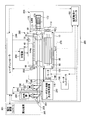
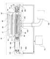
- FIG. 1 is a diagram showing an example of an excimer laser device according to this embodiment.
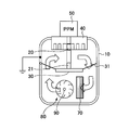
- FIG. 2 is a diagram showing an example of a cross-sectional configuration of the laser chamber according to the present embodiment.
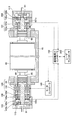
- FIG. 3 is a diagram illustrating an example of a laser chamber according to the first embodiment of the present disclosure.
- FIG. 4 is a diagram showing an example of a cross-sectional configuration of the touch-down bearing of the laser chamber according to the present embodiment.
- FIG. 5 is a diagram illustrating an example of a crossflow fan and a driving mechanism thereof provided in the laser chamber according to the second embodiment of the present disclosure.
- FIG. 1 is a diagram showing an example of an excimer laser device according to this embodiment.
- FIG. 2 is a diagram showing an example of a cross-sectional configuration of the laser chamber according to the present embodiment.
- FIG. 3 is a diagram illustrating an example of a laser chamber according to the first embodiment of the present disclosure.
- FIG. 4 is a diagram showing an example of a cross
- FIG. 6 is a diagram illustrating a configuration of a laser chamber of an excimer laser device according to the third embodiment of the present disclosure.
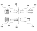
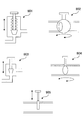
- FIG. 7A is a diagram illustrating an example of a VCR® metal gasket face seal joint.
- FIG. 7B is a diagram illustrating an example of quick coupling.
- FIG. 8 is a diagram illustrating the operation of the laser chamber of the excimer laser device according to the third embodiment of the present disclosure.
- FIG. 9 is a diagram illustrating a configuration of a laser chamber of an excimer laser device according to the fourth embodiment of the present disclosure.
- FIG. 10 is a diagram illustrating an example of a valve.
- FIG. 11 is a diagram illustrating the operation of the laser chamber of the excimer laser device according to the fourth embodiment of the present disclosure.
- Outline Magnetic bearings are used for bearings of the cross flow fan accommodated in the laser chamber of the excimer laser device.
- the magnetic bearing may be installed together with the touchdown bearing in order to prevent damage due to contact between the rotor and the stator when the magnetic bearing is turned off or an error occurs.
- an Au plating layer, a metal containing Ni (Ni, NiP, NiB), and a Cu plating layer are used as a solid lubricant for the touchdown bearing. May be. Since these plating layers are resistant to fluorine gas, corrosion of the touch-down bearing can be suppressed. Moreover, since these plating layers are softer than stainless steel (SUS), it is possible to prevent the touchdown bearing from being consumed when a part of the touchdown bearing is made of stainless steel.
- SUS stainless steel
- the laser chamber it is possible to suppress corrosion of the touchdown bearing by using at least one of an Au plating layer, a Ni-containing metal (Ni, NiP, NiB) plating layer, and a Cu plating layer. It can be done.
- corrosion of the touchdown bearing is suppressed by using at least one of an Au plating layer, a Ni-containing metal (Ni, NiP, NiB) plating layer, and a Cu plating layer. You can get. Therefore, neither disassembly of the magnetic bearing part nor replacement of the touchdown bearing in the periodic maintenance work of the laser chamber may be required. As a result, the number of man-hours for regular maintenance of the laser chamber can be reduced.
- the laser chamber according to the embodiment of the present disclosure may include an intake port configured to supply the purge gas to the touch-down bearing and an exhaust port configured to exhaust the purge gas.
- the discharge excitation laser device according to the embodiment of the present disclosure may include an intake port configured to supply purge gas to the touch-down bearing and an exhaust port configured to exhaust the purge gas. Therefore, purge gas can be flowed to the touchdown bearing. Thereby, dust caused by the corrosion of the touch-down bearing and causing the lock of the touch-down bearing can be eliminated from the touch-down bearing. Therefore, generation
- the “discharge excitation type gas laser device” is a laser device that generates excitation light to the laser gas sealed in the laser chamber by generating discharge in the laser chamber, and generates laser light.
- a laser device that generates excitation light to the laser gas sealed in the laser chamber by generating discharge in the laser chamber, and generates laser light.
- an excimer laser device CO 2 laser device, F 2 laser device and the like.
- Ring direction means the radial direction of the rotating body.
- Magnetic bearing means a drive mechanism of a rotating body that includes an actuator for magnetically levitating the rotor on the stator side and a motor that rotates the rotor.
- Touch-down bearing means an auxiliary bearing that suppresses damage due to contact between the rotor and the stator when the magnetic bearing becomes uncontrollable.
- FIG. 1 is a diagram illustrating an example of an excimer laser device according to the present embodiment.
- An excimer laser device is also a type of discharge excitation gas laser device.
- the excimer laser device may be used as a light source of the exposure apparatus 300 and may output the generated laser light to the exposure apparatus 300.
- the exposure apparatus 300 may include an exposure apparatus controller 301, and may be configured to communicate with the laser controller 240 of the excimer laser apparatus and issue a laser beam output command from the excimer laser apparatus.
- the excimer laser device may include a laser controller 240, a laser resonator 250, and a laser gas supply / exhaust device 210.
- the laser oscillator system 260 includes a laser chamber 10, a laser resonator 250, an energy detector 190, a charger 220, a pulse power module (PPM: Pulse Power Module) 50, and a spectrum detector 200. May be.
- PPM Pulse Power Module
- the laser chamber 10 may include a pair of discharge electrodes 20 and 21 and two windows 60 and 61 that transmit light from the laser resonator 250.
- the laser chamber 10 may be disposed on the optical path of the laser resonator 250.
- the laser chamber 10 further includes a cross flow fan 80, a shaft 90, magnetic bearings 100 and 101, touchdown bearings 110 and 112, a motor 140, a magnetic bearing controller 150, a motor controller 160, and an electrical insulating unit 40. May be included.
- Each of the magnetic bearings 100 and 101 may be provided with one radial magnetic bearing.
- Touch-down bearings 110 and 112 may be provided outside the magnetic bearings 100 and 101.
- the cross flow fan 80 and a part of the shaft 90 are accommodated in the laser chamber 10, and a part of the shaft 90, the magnetic bearings 100 and 101, and the touchdown bearings 110 and 112 are attached to the side wall of the laser chamber 10. Good.
- the laser resonator 250 may include an output coupling mirror (OC) 180 and a line narrowing module (LNM) 170.
- the band narrowing module 170 may include a prism 171 that expands the beam, a rotary stage 172, and a grating 173.
- the grating 173 may be Littrow arranged so that the incident angle and the diffraction angle are the same.
- a grating 173 may be installed on the rotary stage 172 so that the angle at which the laser light enters the grating 173 changes.
- the output coupling mirror (OC) 180 may be a partial reflection mirror that reflects part of the laser light and transmits part of the light.
- the pulse energy detector 190 may include a beam splitter 191 disposed on the optical path of the laser beam output from the output coupling mirror (OC) 180, a condensing lens 192, and an optical sensor 193.
- the spectrum detector 200 may include a beam splitter 201, a condenser lens 202, and a spectrometer 203 arranged on the optical path of the laser light output from the output coupling mirror (OC) 180.
- the spectroscope 203 may include, for example, a diffusion plate, an air gap etalon, a condenser lens, and a line sensor (not shown).
- the pulse power module (PPM) 50 includes a charging capacitor (not shown), may be connected to the discharge electrodes 20 and 21, and may include a switch 51 for discharging the discharge electrodes 20 and 21.
- the charger 220 may be connected to a charging capacitor (not shown) in the pulse power module (PPM) 50.
- PPM pulse power module
- the pressure sensor 230 is a sensor for measuring the laser gas pressure in the laser chamber 10.
- the laser gas pressure measured by the pressure sensor 230 may be transmitted to the laser controller 240.
- the laser chamber 10 is filled with a laser gas.
- the laser gas may be, for example, Ar or Kr as a rare gas, F 2 gas as a halogen gas, Ne or He as a buffer gas, or a mixed gas containing at least F 2 gas.
- the laser gas supply and exhaust device may include a valve and a flow rate control valve (not shown).
- This apparatus is connected to a gas cylinder containing a laser gas (not shown), and may include a valve (not shown) and an exhaust pump.
- the excimer laser apparatus may output laser light to the exposure apparatus 300.
- FIG. 2 is a diagram showing an example of a cross-sectional configuration of the laser chamber 10 according to the present embodiment.
- a heat exchanger 70 may be disposed inside the laser chamber 10.
- the upper electrode 20 is connected and supported to the high voltage output portion of the PPM 50 through the electrical insulating portion 40, and the lower electrode 21 is supported from below by the electrode holder 30 so as to face the electrode 20.
- the wiring 31 may be electrically connected to the metal part of the laser chamber 10.
- the metal part of the laser chamber 10 may be connected to the ground.
- the laser gas in the laser chamber 10 may circulate in the laser chamber 10 by the rotation of the cross flow fan 80.
- the laser gas circulating in the laser chamber 10 may be cooled while being circulated by the heat exchanger 70.
- the laser controller 240 may control the laser gas supply and the disposed device.
- the laser controller 240 may supply laser gas having a predetermined composition into the laser chamber 10 until the inside of the laser chamber 10 reaches a predetermined pressure.
- the laser controller 240 may transmit a magnetic levitation of the cross flow fan 80 and the shaft 90 and a signal for rotating the motor 140 to the magnetic bearing controller 150.
- the magnetic bearing controller 150 may control the shaft 90 of the crossflow fan 80 so that the shaft 90 of the crossflow fan 80 is magnetically levitated and the rotational speed of the crossflow fan 80 becomes a predetermined rotational speed via the motor controller 160.
- the laser controller 240 may receive the target pulse energy Et and the oscillation trigger from the exposure apparatus controller 301.
- a predetermined charging voltage (Vhv) may be set in the charger 220 such that the laser light output from the laser controller 240 becomes the target pulse energy Et.
- the switch 51 in the pulse power module (PPM) 50 may be operated in synchronization with the oscillation trigger to apply a high voltage between the electrodes 20 and 21.
- the laser gas is excited, and laser oscillation can be performed by the laser resonator 250 including the output coupling mirror (OC) 180 and the grating 172.
- the narrow-band laser beam can be output from the output coupling mirror (OC) 180 by the prism 171 and the grating 172.
- the pulse energy detector 190 can detect the pulse energy E of the laser beam output from the output coupling mirror (OC).
- the laser controller 240 may store at least one of the charging voltage Vhv at this time and the output pulse energy E. Further, the laser controller 240 sets the charging voltage Vhv so that the pulse energy E of the output laser light becomes the target pulse energy Et based on the difference ⁇ E between the target pulse energy Et and the actually output energy E. Feedback control may be performed.
- the laser controller 240 may control the laser gas supply / exhaust device 210 to supply the laser gas into the ray chamber 10 until a predetermined pressure is reached. Further, when the charging voltage Vhv is lower than the minimum value of the allowable range, the laser controller 240 may control the laser gas supply and exhaust device 210 to exhaust the laser gas from the laser chamber 10 until a predetermined pressure is reached. .
- a part of the laser beam output from the output coupling mirror (OC) 180 may be sampled by the beam splitter 201 and made incident on the spectroscope 203.
- the center wavelength of the laser beam can be measured by the spectroscope 203.
- LNM narrowband module
- the excimer laser device is not necessarily a narrow-band laser device, and may be an excimer laser device that outputs natural oscillation light.
- a high reflection mirror may be arranged instead of the narrowband module (LNM) 170.
- the excimer laser device can output laser light.
- a part of the cross flow fan 80 and the shaft 90 is accommodated in the laser chamber 10, and magnetic bearings 100 and 101 which are driving units of the cross flow fan 80 and the shaft 90, Touch-down bearings 110 and 112, which are auxiliary bearings for the magnetic bearings 100 and 101, are installed on the side wall of the laser chamber 10, but the shaft 90 and the magnetic bearings 100 and 101 have a gap.
- the laser gas in 10 reaches the touchdown bearings 110 and 112.
- fluorine gas may be used as the laser gas.
- the touchdown bearings 110 and 112 are made of stainless steel (SUS), which is not very resistant to fluorine gas, and the durability of the touchdown bearings 110 and 112 may be a problem.
- SUS stainless steel
- this problem can be solved by plating and covering the touchdown bearings 110 and 112 with a metal material having high fluorine gas resistance.
- the configuration of the touchdown bearings 110 and 112 used in the laser chamber and the excimer laser apparatus according to the present embodiment will be described in more detail.
- FIG. 3 is a diagram illustrating an example of a laser chamber according to the first embodiment of the present disclosure.
- the laser chamber 10 according to the first embodiment includes a cross flow fan 80, shafts 90 and 91, a labyrinth structure 95, magnetic bearings 100 and 101, gap sensors 105 and 106, and touchdown bearings 110 and 112. It's okay.
- the magnetic bearings 100 and 101 may have inner ring magnetic bodies 100a and 101a, outer ring electromagnetic coils 100b and 101b, and gaps 100c and 101c, respectively.
- the motor 140 may include a stator 141 and a rotor 142. Further, a magnetic bearing controller 150, a motor controller 160, and a laser controller 240 may be provided outside the laser chamber 10.
- the gap sensors 105 and 106 may be sensors for detecting the gaps 100c and 101c of the magnetic bearings 100 and 101, respectively.
- the gap sensors 105 and 106 may include coils 105a and 106a and magnets 105b and 106b, respectively.
- a counter electromotive force is generated in the coils 105a and 106a due to the electromagnetic induction action, and a current flows.
- the gaps 100c and 101c of the magnetic bearings 100 and 101 can be detected from the current values flowing through the coils 105a and 106a.
- the magnetic bearings 100 and 101 may include inner ring magnetic bodies 100a and 101a and outer ring electromagnetic coils 100b and 101b. By controlling the current value of the outer ring electromagnetic coils 100b and 101b, the repulsive force generated between the inner ring magnetic bodies 100a and 101a can be controlled, and the shaft 90 can be an actuator for magnetically levitating.
- the magnetic bearing controller 150 controls the magnetic levitation force generated by the outer ring electromagnetic coils 100b and 101b, which are actuators, from the gaps 100c and 101c detected by the gap sensors 105 and 106, and appropriately maintains the gaps 100c and 101c. Take control.
- the motor controller 160 performs control for appropriately driving the motor 140 to rotate.
- the laser controller 240 is as described with reference to FIG. Further, in FIG. 3, the shaft 91 at the location of the touchdown bearings 110 and 112 is configured to have a smaller diameter than the shaft 90.
- a labyrinth structure 95 is provided between the motor 140 and the magnetic bearings 100 and 101 and the inside of the laser chamber 10, but it is difficult to completely shield the laser gas in the labyrinth structure 95.
- the laser gas reaches the motor 140 and the magnetic bearing 100 through the structure 95.
- the motor 140 has a gap between the stator 141 and the rotor 142, and the magnetic bearings 100 and 101 also have gaps 100c and 101c between the inner ring magnetic bodies 100a and 101a and the outer ring electromagnetic coils 100b and 101b.
- the laser gas that has passed through 95 can reach the touchdown bearings 110 and 112 located further outside.
- an Au plating layer, a Ni-containing plating layer, or a Cu plating layer is formed as a fixed lubricant on the surfaces of the inner ring and the outer ring of the touchdown bearing, and the inner ring and the outer ring are formed.
- the surface may be coated.
- FIG. 4 is a view showing an example of a cross-sectional configuration of the touch-down bearing 110 of the laser chamber according to the present embodiment. Since the touchdown bearing 112 has the same configuration, only the touchdown bearing 110 will be described as an example.
- an inner ring (also referred to as “inner race”) 113 is provided around the shaft 91 with a space therebetween, and a plurality of balls 116 are in contact with the outer peripheral surface of the inner ring 113.
- an outer ring (which may be referred to as an “outer race”) 114 is also provided on the outside of the ball 116 in contact with the ball 116. That is, the ball 116 is provided between the inner ring 113 and the outer ring 114 so as to be sandwiched in the radial direction.
- a solid lubricant 115 may be formed on the surfaces of the inner ring 113 and the outer ring 114.
- the solid lubricant 115 may be composed of any one of an Au plating layer, a Cu plating layer, and a Ni-containing plating layer.
- the Ni-containing plating layer may be various plating layers as long as it is a metal plating layer containing Ni.
- the Ni-containing plating layer may be a Ni plating layer, a NiP plating layer, or a NiB plating layer.
- these metals are resistant to fluorine gas, corrosion can be suppressed. Further, since these metals are soft, they can function as a lubricant that reduces friction between the inner ring 113 and the outer ring 114 with the ball 116.
- the touchdown bearings 110 and 112 used in the laser chamber 10 are unstable in discharge due to generation of impurities in the laser gas and absorb laser light, so that oil cannot be used as a lubricant. Therefore, by using a soft metal material and functioning as the solid lubricant 115, it can serve as a lubricant and reduce the consumption of the touch-down bearing while suppressing the generation of impurity gas in the laser gas.
- the solid lubricant 115 only needs to cover the outer peripheral surface of the inner ring 113 and the inner peripheral surface of the outer ring 114 in contact with the ball 116 in order to perform the function of only the lubricant. Good. However, from the viewpoint of inhibiting corrosion from fluorine gas, it is preferable that the solid lubricant 115 is formed on the entire surfaces of the inner ring 113 and the outer ring 114. Therefore, the solid lubricant 115 is formed on the entire inner ring 113 and the outer ring 114. May be.
- the Au plating layer, Cu plating layer, and Ni-containing plating layer used for the solid lubricant 115 may literally be formed by plating.
- the Au plating layer and the Cu plating layer may be formed by electroplating
- the Ni-containing plating layer may be formed by electroless plating.
- the Ni-containing plating layer can provide sufficient adhesion by electroless plating, but the Au plating layer and the Cu plating layer are each suitable because sufficient adhesion cannot be obtained unless electroplating is performed.
- a plating process may be used.
- the inner ring 113 and the outer ring 114 may be made of stainless steel (SUS440C), for example, except for the solid lubricant 115.
- Stainless steel (SUS440C) does not necessarily have good resistance to fluorine gas, but by providing a solid lubricant 115 on the surface, it can become touchdown bearings 110 and 112 suitable for the laser chamber 10.
- the ball 116 may be made of various materials depending on the application, but may be a ceramic ball 116 made of ceramics, for example.
- the material of the ceramic ball 116 is preferably an alumina ceramic that does not easily react with F 2 gas.
- the Au plating layer or Cu plating layer is formed on the surface of the inner ring 113 and the outer ring 114 of stainless steel (SUS440C), first, metal plating containing about 0.5 ⁇ m of nickel is performed by electroless plating to form a base. Further, an Au plating layer or Cu plating layer having a predetermined thickness may be formed by electroplating. As is generally known, the adhesion of the plating layer can be improved by performing such multilayer plating.
- the thickness of the Au plating layer or Cu plating layer may be in the range of 2 to 13 ⁇ m, for example.
- the plating layer of predetermined thickness can be formed with an electric current and electricity supply time.
- the Ni-containing plating layer can be directly plated on the surface of stainless steel (SUS440C).
- the thickness of the plating layer may be in the range of 2 to 13 ⁇ m, for example.
- the Ni-containing plating layer may be formed by electroless plating.
- the inner ring 113 and / or the outer ring 114 are immersed for a predetermined time in a plating bath using hypophosphorous acid and diborane as a reducing agent, respectively, so that a predetermined thickness is obtained.
- a plating layer may be formed.
- any one of the Au plating layer, the Cu plating layer, and the Ni-containing plating layer is provided on the surface of the touchdown bearings 110 and 112.
- the coating layer corrosion of the inner ring 113 and the outer ring 114 can be suppressed, wear of the touchdown bearings 110 and 112 can be suppressed, and the bearing function can be performed smoothly over a long period of time.
- FIG. 5 is a diagram illustrating an example of a cross flow fan 80 provided in the laser chamber according to the second embodiment of the present disclosure and a driving mechanism thereof.
- the motor 140 is coaxially connected to the crossflow fan 80, and the first touchdown bearing 110, the motor 140 and the crossflow fan are outside the motor 140.
- the magnetic bearing 100 and the second touchdown bearing 111 are provided between the magnetic bearing 100 and the second touchdown bearing 111, and the magnetic bearing 101 and the third touchdown bearing 112 are provided outside the cross flow fan 80. That is, the third embodiment differs from the first embodiment in which only two of the touchdown bearings 110 and 112 are provided in that three touchdown bearings 110, 111, and 112 are provided.
- the touch-down bearings 110 and 112 may not be provided only at both outer ends, but the touch-down bearing 111 may be provided between the cross flow fan 80 and the motor 140.
- the first and third touch bearings 110 and 112 at both ends have a thin shaft 91 and a small load.
- the second touch-down bearing 111 is disposed between the motor 140 as the driving source and the cross flow fan 80 as the driving target, and the shaft 90 is also thickly configured at a place where a large load is applied. is there.
- the Au plating layer, the Cu plating layer, and the Ni-containing plating layer are exemplified as the plating layer to be the solid lubricant 115.
- the Au plating layer and the Cu plating layer are more than the Ni-containing plating layer. It can be a plating layer that is soft and can withstand relatively large loads.
- the Cu plating layer is less reactive with F 2 gas than the Au plating layer. Therefore, a Cu plating layer is preferable as the solid lubricant for the touch-down bearing of the laser chamber using a laser gas containing F 2 gas.
- the thickness of the Cu plating layer used as the solid lubricant 115 for the second touchdown bearing 111 may be 10 ⁇ m.
- the Cu plating layer does not have a very high processing accuracy (accuracy in controlling the film thickness of the plating layer), and the tolerance is ⁇ 2 to 3 ⁇ m. Therefore, the Cu plating layer used as the solid lubricant 115 for the second touchdown bearing 111 may preferably have a thickness of 10 ⁇ 3 ⁇ m, more preferably 10 ⁇ 2 ⁇ m.
- first and third touchdown bearings 110 and 112 outside both ends are required to have a smaller size and a smaller tolerance of the plating layer, although the load is smaller than that of the second touchdown bearing.
- the Ni-containing plating layer is harder than the Cu plating layer, but has a small tolerance and enables highly accurate film thickness control. is there.
- the film thickness of the solid lubricant 114 is set to 10 ⁇ m, the NiP plating layer can be easily formed with an accuracy of 10 ⁇ 1 ⁇ m. Therefore, although the load is smaller than that of the second touchdown bearing 111, the NiP plating layer is used for the first and third touchdown bearings 110 and 112 that require more accurate film thickness control. Also good.
- the solid lubricant 115 used for the first and third touchdown bearings 110 and 112 is also soft and can use a Cu plating layer that can withstand a large load. Likewise preferred. Therefore, when the processing accuracy requirements of the first and third touchdown bearings 110 and 112 are not so high, or when the film thickness can be controlled with high accuracy even using the Cu plating layer, the first to the first touchdown bearings 110 and 112 are used.
- a Cu plating layer may be used as the solid lubricant 115 for all of the three touchdown bearings 110 to 112.
- Table 1 shows the above explanation as a table.
- the left side is a case where a Cu plating layer is used as the solid lubricant 115 for all of the first to third touchdown bearings 110 to 112.
- a Cu plating layer is used as the solid lubricant 115 for the second touchdown bearing 111
- a NiP plating layer is used as the solid lubricant 115 for the first and third touchdown bearings 110 and 112. This is the case.
- an Au plating layer may be used for all of the first to third touchdown bearings 110 to 112, or plating used as the solid lubricant 115 depending on the application.
- the layer materials may be in various combinations.
- the thickness of the solid lubricant 115 has been described with an example of 10 ⁇ m in this embodiment, but various changes may be made depending on the application, for example, within the range of 2 to 13 ⁇ m. An appropriate film thickness may be selected accordingly.
- the example in which the touchdown bearings 110 to 112 are installed at three locations has been described.
- more touchdown bearings can be installed and the load required at each location is large.
- an appropriate plating layer corresponding to each location may be used as the solid lubricant 115.
- touchdown bearings are provided at three or more locations, and an appropriate plating layer is provided according to the load and processing accuracy at each location.
- an appropriate plating layer is provided according to the load and processing accuracy at each location.
- FIG. 6 is a diagram illustrating a configuration of a laser chamber of an excimer laser device according to the third embodiment of the present disclosure.
- the laser chamber 10 of the excimer laser as illustrated in FIG. 6 may include a pair of electrodes 20 and 21, an electrode holder 30, an electrical insulating unit 40, and two windows 60 and 61.
- the pair of electrodes 20 and 21, the electrode holder 30, the electric insulating portion 40, and the two windows 60 and 61 as illustrated in FIG. 6 may be the same as those illustrated in FIG.
- the laser chamber 10 may further include a cross flow fan 80, shafts 90 and 91, magnetic bearings 100 and 101, touchdown bearings 110, 111, and 112, and a motor 140.
- the cross flow fan 80, shafts 90 and 91, magnetic bearings 100 and 101, touchdown bearings 110, 111, and 112, and the motor 140 as illustrated in FIG. 6 are similar to those illustrated in FIG. There may be.
- the laser chamber 10 may further include two intake ports 401 and 402 and one exhaust port 403.
- the intake port 401 may be configured to be able to supply purge gas to the touchdown bearings 110 and 111.
- the intake port 401 may be configured to be connected to a pipe configured to be able to supply purge gas.
- the intake port 401 may be configured to be connected to a joint that is connected to a pipe configured to be able to supply purge gas.
- the air inlet 401 may be provided on the opposite side of the cross-flow fan 80 (outside the touch-down bearing 110) with respect to the touch-down bearing 110 in the direction of the shaft 90.
- the air inlet 402 may be configured to be able to supply purge gas to the touchdown bearing 112.
- the intake port 402 may be configured to be connected to a pipe configured to be able to supply purge gas.
- the intake port 402 may be configured to be connected to a joint that is connected to a pipe configured to be able to supply purge gas.
- the air inlet 402 may be provided on the opposite side of the cross-flow fan 80 (outside the touch-down bearing 112) with respect to the touch-down bearing 112 in the direction of the shaft 91.
- the exhaust port 403 may be configured to be able to exhaust the purge gas supplied to the touchdown bearings 110, 111, and 112.
- the exhaust port 403 may be configured to be connected to a pipe configured to be able to exhaust the purge gas.
- the exhaust port 403 may be configured to be connected to a joint connected to a pipe configured to be able to exhaust the purge gas.
- the exhaust port 403 may be provided between the touchdown bearings 111 and 112 in at least one direction of the shaft 90 and the shaft 91.
- the laser chamber 10 may further include three joints 404, 405, and 406.
- the joint 404 may be connected to the air inlet 401.
- the joint 405 may be connected to the air inlet 402.
- the joint 406 may be connected to the exhaust port 403.
- Each of the joint 404 and the joint 405 may be, for example, a commercially available VCR® metal gasket face seal joint.
- the joint 406 may be a quick coupling including an O-ring, for example.
- the O-ring included in the quick coupling may be made of a resin containing fluorine.
- the laser chamber 10 may further include three lids 407, 408, and 409.
- the lid 407 may be connected to the intake port 401.
- the lid 407 may be connected to the joint 404.
- the lid 407 may seal the intake port 401 directly.
- the lid 407 may seal the intake port 401 via the joint 404.
- the lid 408 may be connected to the air inlet 402.
- the lid 408 may be connected to the joint 405.
- the lid 408 may seal the air inlet 402 directly.
- the lid 408 may seal the intake port 402 via the joint 405.
- the lid 409 may be connected to the exhaust port 403.
- the lid 409 may be connected to the joint 406.
- the lid 409 may seal the exhaust port 403 directly.
- the lid 409 may seal the exhaust port 403 via the joint 406.
- FIG. 7A is a diagram illustrating an example of a VCR (registered trademark) metal gasket type face seal joint.
- the VCR® metal gasket face seal joint may be such that the gasket 501 is sandwiched between two glands 504 and 505 by combining a male nut 502 and a female nut 503, for example.
- the VCR® metal gasket face seal joint may be such that the gasket 501 is sandwiched between the body 506 and the gland 504 by combining the body 506 and the female nut 503, for example.
- FIG. 7B is a diagram illustrating an example of quick coupling.
- the quick coupling may be such that the center ring 602 provided with the O-ring 601 is sandwiched between the two flanges 603 and 604 and the center ring 602 and the flanges 603 and 604 are tightened with the clamp 605.
- FIG. 8 is a diagram illustrating the operation of the laser chamber of the excimer laser device according to the third embodiment of the present disclosure.
- fluorine atoms When supplying a laser gas containing fluorine gas to the laser chamber 10 of the excimer laser and causing a discharge between the pair of electrodes 20 and 21, fluorine atoms may be generated from the laser gas. Fluorine atoms generated from the laser gas can react with the touchdown bearings 110, 111, and 112. If the touchdown bearings 110, 111, and 112 are made of stainless steel (SUS), iron fluoride particles can be generated as dust particles. The dust particles generated in the touchdown bearings 110, 111, and 112 may absorb moisture in the atmosphere and expand when the laser chamber 10 is opened for maintenance of the laser chamber 10.
- SUS stainless steel
- the expanded dust particles can fill the gap between the touchdown bearing 110 and the shaft 90, the gap between the touchdown bearing 111 and the shaft 90, and the gap between the touchdown bearing 112 and the shaft 91.
- the expanded dust particles can accumulate on the inner and outer rings and surfaces of the bearing balls of the touchdown bearings 110, 111 and 112. As a result, the touchdown bearings 110, 111, and 112 may be locked.
- a pipe may be directly connected to the intake port 401.
- a pipe may be connected to the air inlet 401 via the joint 404.
- the pipe can be more easily connected to the intake port 401.
- a pipe may be directly connected to the air inlet 402.
- a pipe may be connected to the air inlet 402 via the joint 405.
- the purge gas supply device 701 may supply purge gas to the intake port 401 and the intake port 402.
- the purge gas may be a gas containing neither moisture nor impurities.
- the purge gas may be, for example, at least one of nitrogen (N 2 ) gas, helium (He) gas, carbon dioxide (CO 2 ) gas, and combinations thereof.
- the purge gas supply device 701 may be a tank that stores a purge gas liquid.
- a pipe may be directly connected to the exhaust port 403.
- a pipe may be connected to the exhaust port 403 via the joint 406.
- the pipe connected to the exhaust port 403 may be connected to the exhaust device 702.
- the exhaust device 702 may exhaust the gas supplied from the air inlet 401 and the air inlet 402 into the laser chamber 10 to the outside of the laser chamber 10.
- the exhaust device 702 may be a dry pump.
- the purge gas supply device 701 When the purge gas supply device 701 is connected to the intake ports 401 and 402 and the exhaust device 702 is connected to the exhaust port 403, the purge gas is supplied into the laser chamber 10 and the purge gas is exhausted outside the laser chamber 10. be able to.
- dust particles adhering to the touch-down bearings 110, 111, and 112 can be removed.
- the dust particles removed from the touchdown bearings 110, 111, and 112 can be removed outside the laser chamber 10 through the exhaust port 403 together with the purge gas by the exhaust device 702.
- dust particles attached to the touchdown bearings 110, 111, and 112 may be removed by a purge gas. In that case, dust particles that may cause the touchdown bearings 110, 111, and 112 to lock can be removed in advance. Since the occurrence of locking of the touchdown bearings 110, 111, and 112 can be suppressed, the frequency of replacement of the touchdown bearings 110, 111, and 112 can be reduced.
- the purge gas can flow more efficiently. As a result, dust particles attached to the touchdown bearings 110, 111, and 112 can be more efficiently removed.
- FIG. 9 is a diagram illustrating a configuration of a laser chamber of an excimer laser device according to the fourth embodiment of the present disclosure.
- the laser chamber 10 of the excimer laser as illustrated in FIG. 9 may include a pair of electrodes 20 and 21, an electrode holder 30, an electrical insulating unit 40, and two windows 60 and 61.
- the pair of electrodes 20 and 21, the electrode holder 30, the electrical insulating portion 40, and the two windows 60 and 61 as illustrated in FIG. 9 may be the same as those illustrated in FIGS. .
- the laser chamber 10 may further include a cross flow fan 80, shafts 90 and 91, magnetic bearings 100 and 101, touchdown bearings 110, 111, and 112, and a motor 140.
- the cross flow fan 80, shafts 90 and 91, magnetic bearings 100 and 101, touchdown bearings 110, 111, and 112, and the motor 140 as illustrated in FIG. 9 are the same as those illustrated in FIGS. It may be anything.
- the laser chamber 10 may further include air inlets 401 and 402, an air outlet 403, and joints 404, 405, and 406. As illustrated in FIG. 9, the intake ports 401 and 402, the exhaust port 403, and the joints 404, 405, and 406 may be similar to those illustrated in FIGS. The diameter of each of the intake ports 401 and 402 may be smaller than the diameter of the exhaust port 403.
- the laser chamber 10 as illustrated in FIG. 9 may further include three valves 801, 802, and 803.
- Each of the valves 801, 802, and 803 may independently be at least one of, for example, a bellows valve, a ball valve, a needle valve, a butterfly valve, and a gate valve.
- the valves 801, 802, and 803 may be connected to the intake port 401, the intake port 402, and the exhaust port 403, respectively.
- the valve 801 When the valve 801 is used for the intake port 401 having a smaller diameter than that of the exhaust port 403, the valve 801 may be at least one of a bellows valve, a ball valve, and a needle valve.
- valve 802 When the valve 802 is used for the intake port 402 having a smaller diameter than that of the exhaust port 403, the valve 802 may be at least one of a bellows valve, a ball valve, and a needle valve.
- the valve 803 When the valve 803 is used for the exhaust port 403 having a larger diameter than that of each of the valves 801 and 802, the valve 803 may be at least one of a butterfly valve and a gate valve, for example. .
- FIG. 10 is a diagram illustrating an example of a valve.
- the bellows valve 901 is a valve that stops the flow of fluid by pressing a conical valve body provided at the tip of a valve rod provided with a bellows-like portion on a valve seat surface provided inside the valve box. Good.
- the ball valve 902 may be a valve that opens and closes the flow path by rotating a spherical valve body having a cavity.
- the needle valve 903 may be a valve that stops the flow of fluid by pressing a conical valve body against a valve seat surface provided inside the valve box.
- the butterfly valve 904 may be a valve that opens and closes the flow path by rotating a disc-shaped valve body.
- the gate valve 905 may be a valve that opens and closes the flow path by operating a disc-shaped valve element housed in the valve box of the valve substantially at right angles to the flow path.
- the intake port 401 and the valve 801 may be connected to the purge gas supply device 701 through a pipe and a valve 804.
- the intake port 402 and the valve 802 may be connected to the purge gas supply device 701 via a pipe and valve 805.
- the intake port 401 and the valve 801 may be connected to the exhaust device 702 via a pipe and valve 806.
- the intake port 402 and the valve 802 may be connected to the exhaust device 702 via a pipe and valve 807.
- the exhaust port 403 and the valve 803 may be connected to the exhaust device 702 via a pipe.
- the purge gas supply device 701 and the exhaust device 702 may be similar to those illustrated in FIG.
- the valve 801 may be connected to the valves 804 and 806 via piping.
- the valve 801 may be connected to the valves 804 and 806 via the joint 404 and piping.
- the valve 802 may be connected to the valves 805 and 807 via piping.
- the valve 802 may be connected to the valves 805 and 807 via a joint 405 and piping.
- the valve 803 may be connected to the exhaust device 702 via a pipe.
- the valve 803 may be connected to the exhaust device 702 via the joint 406 and piping. If the valves 801, 802, and 803 are connected to the joints 404, 405, and 406, respectively, the laser chamber 10 can be more easily connected to the purge gas supply device 701 and the exhaust device 702.
- the air in the laser chamber 10 may be exhausted in advance by closing the valves 804 and 805 and opening the valves 801, 802, 803, 806, and 807. Since the air in the laser chamber 10 can be exhausted, the occurrence of lock on the touch-down bearings 110, 111, and 112 that can be caused by moisture contained in the air can be suppressed.
- the purge gas may be supplied into the laser chamber 10 and the purge gas may be exhausted from the laser chamber 10 by closing the valve 806 and the valve 807 and opening the valves 801, 802, 803, 804, and 805.
- the dust particles adhering to the touchdown bearings 110, 111, and 112 can be removed from the touchdown bearings 110, 111, and 112 and removed from the laser chamber 10 to the outside by the purge gas supplied to the laser chamber 10. It is possible to suppress the occurrence of lock on the touchdown bearings 110, 111, and 112 that may be caused by dust particles attached to the touchdown bearings 110, 111, and 112.
- the joint 406 is not connected to the purge gas supply device 701 but is connected to the exhaust device 702. Therefore, the joint 406 is not necessarily included in the laser chamber 10. Even in the case where the joint 406 is not included in the laser chamber 10, it is considered that the moisture in the atmosphere entering the laser chamber 10 through the exhaust port 403 is less. Even when the joint 406 is not included in the laser chamber 10, the lock-down of the touchdown bearings 110, 111, and 112 is not necessarily likely to occur easily.
- FIG. 11 is a diagram illustrating the operation of the laser chamber of the excimer laser device according to the fourth embodiment of the present disclosure.
- FIG. 11 illustrates the operation of the laser chamber 10 as illustrated in FIG.
- the valves 801, 802, and 803 may be closed.
- the valves 804, 805, 806, and 807 may be opened.
- step S1001 the valves 804, 805, 806, and 807 may be closed.
- step S1002 pipes connected to the purge gas supply device 701 and the exhaust device 702 as illustrated in FIG. 9 may be connected to the joints 404, 405, and 406 of the laser chamber 10.
- step S1003 the valves 806 and 807 may be opened.
- step S1004 the exhaust device 702 may be operated. By operating the exhaust device 702, the air in the pipe may be exhausted via the valves 806 and 807.
- valves 806 and 807 may be closed in step S1005.
- the operation of the exhaust device 702 may be stopped.
- step S1006 the valves 804 and 805 may be opened.
- step S1007 the valves 801, 802, and 803 may be opened.
- the exhaust device 702 may be operated.
- the purge gas may be supplied from the purge gas supply device 701 into the laser chamber 10 by operating the exhaust device 702.
- the purge gas By supplying a purge gas from the purge gas supply device 701 into the laser chamber 10, dust particles attached to the touchdown bearings 110, 111, and 112 may be removed from the touchdown bearings 110, 111, and 112.
- the purge gas supplied to the laser chamber 10 may be exhausted from the laser chamber 10 together with dust particles removed from the touchdown bearings 110, 111, and 112.
- step S1009 the valves 801, 802, 803, 804, and 805 may be closed.
- the operation of the exhaust device 702 may be stopped.
- step 1010 the pipes connected to the purge gas supply device 701 and the exhaust device 702 as illustrated in FIG. 9 may be separated from the joints 404, 405, and 406.
- At least one of an Au plating layer, a Ni-containing plating layer, and a Cu plating layer is used for the touch-down bearing, and an intake port for supplying a purge gas to the touch-down bearing and an exhaust for exhausting the purge gas.
- a mouth may be provided.
Landscapes
- Engineering & Computer Science (AREA)
- Physics & Mathematics (AREA)
- Electromagnetism (AREA)
- General Engineering & Computer Science (AREA)
- Plasma & Fusion (AREA)
- Optics & Photonics (AREA)
- Mechanical Engineering (AREA)
- Chemical & Material Sciences (AREA)
- Chemical Kinetics & Catalysis (AREA)
- Lasers (AREA)
- Magnetic Bearings And Hydrostatic Bearings (AREA)
- Rolling Contact Bearings (AREA)
Abstract
レーザチャンバに用いられるタッチダウンベアリングのフッ素ガスによる腐食を抑制するとともに、タッチダウンベアリングの消耗を抑制する。 一対の放電電極及びガス循環用のファンを収容したレーザチャンバであって、 前記ファンの軸を非接触で支持可能な磁気軸受けと、 該磁気軸受けの制御不能時に軸受けとして機能とするタッチダウンベアリングを備え、 該タッチダウンベアリングの固体潤滑材として、Auめっき層、Ni含有めっき層及びCuめっき層の少なくともいずれか1つが用いられてよい。
Description
本開示は、レーザチャンバ及び放電励起式ガスレーザ装置に関する。
半導体集積回路の微細化、高集積化につれて、半導体露光装置(以下、「露光装置」という)においては、解像力の向上が要請されている。このため、露光用光源から放出される光の短波長化が進められている。近年、露光用光源には、従来の水銀ランプに代わってガスレーザ装置が用いられている。現在、露光用のガスレーザ装置としては、波長248nmの深紫外光を放出するKrFエキシマレーザ装置、ならびに波長193nmの真空紫外光を放出するArFエキシマレーザ装置が用いられている。
次世代の露光技術としては、露光装置側の露光用レンズとウェハーとの間を液体で満たし、屈折率を変えることにより露光用光源の見かけの波長を短波長化する液浸露光も行われている。ArFエキシマレーザ装置を露光用光源として液侵露光では、ウェハーには水中における波長134nmに相当する真空紫外光が照射される。この技術をArF液浸露光(又はArF液浸リソグラフィー)という。
KrF、ArFエキシマレーザ装置の自然発振のスペクトル線幅は約350~400pmと広いため、これらの投影レンズが使用されると色収差が発生し、解像力が低下する。そこで、色収差が無視できる程度となるまで、ガスレーザ装置から放出されるレーザビームのスペクトル線幅を狭帯域化する必要がある。このため、ガスレーザ装置のレーザ共振器内には、狭帯域化素子(エタロンやグレーティング等)を有する狭帯域化モジュール(Line Narrowing Module)が設けられ、スペクトル線幅の狭帯域化が実現されている。このようにスペクトル線幅が狭帯域化されるレーザ装置を狭帯域化レーザ装置という。
本開示の実施形態によれば、一対の放電電極及びガス循環用のファンを収容したレーザチャンバであって、前記ファンの軸を非接触で支持可能な磁気軸受けと、該磁気軸受けの制御不能時に軸受けとして機能とするタッチダウンベアリングを備え、該タッチダウンベアリングの固体潤滑材として、Auめっき層、Ni含有めっき層及びCuめっき層の少なくともいずれか1つが用いられたレーザチャンバが提供されてもよい。
本開示の実施形態によれば、前記レーザチャンバと、前記レーザチャンバのレーザの発生を制御するレーザコントローラと、を備える、放電励起式ガスレーザ装置が提供されてもよい。
本開示の実施形態によれば、一対の電極、レーザガスを循環させることが可能であるように構成されたファン、非接触の様式で前記ファンの軸を磁気的に支持することが可能であるように構成された磁気軸受け、前記磁気軸受けの故障の際に前記ファンの軸を支持することが可能であるように構成されたタッチダウンベアリング、前記タッチダウンベアリングにパージガスを供給することが可能であるように構成された吸気口、及び、前記パージガスを排気することが可能であるように構成された排気口を備える、レーザチャンバが提供されてもよい。
本開示の実施形態によれば、上記のレーザチャンバ、及び前記レーザチャンバにおけるレーザ光の発生を制御するように構成されたレーザコントローラを備える、放電励起式ガスレーザ装置が提供されてもよい。
本開示のいくつかの実施形態を、単なる例として、添付の図面を参照して以下に説明する。
図1は、本実施形態に係るエキシマレーザ装置の一例を示した図である。
図2は、本実施形態に係るレーザチャンバの断面構成の一例を示した図である。
図3は、本開示の実施形態1に係るレーザチャンバの一例を示した図である。
図4は、本実施形態に係るレーザチャンバのタッチダウンベアリングの断面構成の一例を示した図である。
図5は、本開示の実施形態2に係るレーザチャンバに備えられたクロスフローファン及びその駆動機構の一例を示した図である。
図6は、本開示の実施形態3に係るエキシマレーザ装置のレーザチャンバの構成を例示する図である。
図7Aは、VCR(登録商標)メタル・ガスケット式面シール継ぎ手の例を例示する図である。
図7Bは、クイックカップリングの例を例示する図である。
図8は、本開示の実施形態3に係るエキシマレーザ装置のレーザチャンバの動作を例示する図である。
図9は、本開示の実施形態4に係るエキシマレーザ装置のレーザチャンバの構成を例示する図である。
図10は、バルブの例を例示する図である。
図11は、本開示の実施形態4に係るエキシマレーザ装置のレーザチャンバの動作を例示する図である。
以下、本開示の実施形態について、下記の目次の流れに沿って説明する。
目次
1.概要
2.用語の説明
3.エキシマレーザ装置
3.1 構成
3.2 動作
4.エキシマレーザ装置のレーザチャンバに備えられたタッチダウンベアリング
4.1 実施形態1
4.2 実施形態2
5.エキシマレーザ装置のレーザチャンバ
5.1 実施形態3
5.2 実施形態4
1.概要
2.用語の説明
3.エキシマレーザ装置
3.1 構成
3.2 動作
4.エキシマレーザ装置のレーザチャンバに備えられたタッチダウンベアリング
4.1 実施形態1
4.2 実施形態2
5.エキシマレーザ装置のレーザチャンバ
5.1 実施形態3
5.2 実施形態4
以下、本開示の実施形態について、図面を参照しながら詳しく説明する。以下に説明される実施形態は、本開示の一例を示すものであって、本開示の内容を限定するものではない。また、各実施形態で説明される構成及び動作の全てが本開示の構成及び動作として必須であるとは限らない。なお、同一の構成要素には同一の参照符号を付して、重複する説明を省略する。
1.概要
エキシマレーザ装置のレーザチャンバに収容されているクロスフローファンの軸受けには、磁気軸受けが使用されている。磁気軸受けは、磁気ベアリングの電源が切れた時やエラーが出た時に、ロータとステータの接触による破損を防ぐため、タッチダウンベアリングとともに設置してもよい。
エキシマレーザ装置のレーザチャンバに収容されているクロスフローファンの軸受けには、磁気軸受けが使用されている。磁気軸受けは、磁気ベアリングの電源が切れた時やエラーが出た時に、ロータとステータの接触による破損を防ぐため、タッチダウンベアリングとともに設置してもよい。
しかしながら、エキシマレーザ装置では、レーザチャンバ内でフッ素ガス(F2)を用いるため、フッ素に耐性の小さいステンレス等でタッチダウンベアリングが構成された場合には、タッチダウンベアリングが腐食して、さらに、タッチダウンベアリングが消耗して回転しなくなることがあり得た。
そこで、本開示の実施形態に係るレーザチャンバ及び放電励起式レーザ装置では、タッチダウンベアリングの固体潤滑材としてAuめっき層、Niを含む金属(Ni,NiP、NiB)めっき層、Cuめっき層を使用してもよい。これらのめっき層は、フッ素ガスに耐性を有するため、タッチダウンベアリングの腐食を抑制することができる。また、これらのめっき層はステンレス(SUS)に比べて柔らかいので、タッチダウンベアリングの一部がステンレスで構成されている場合にタッチダウンベアリングが消耗するのを抑制し得る。
また、タッチダウンベアリングの腐食及び消耗の少なくとも一つが生じると、レーザチャンバの定期的なメンテナンスの作業の際に磁気軸受け部分を分解すると共にタッチダウンベアリングを交換することが必要であり得た。
本開示の実施形態に係るレーザチャンバにおいては、Auめっき層、Niを含む金属(Ni,NiP、NiB)めっき層、及びCuめっき層の少なくとも一つの使用によりタッチダウンベアリングの腐食を抑制することができ得る。本開示の実施形態に係る放電励起式レーザ装置においては、Auめっき層、Niを含む金属(Ni,NiP、NiB)めっき層、及びCuめっき層の少なくとも一つの使用によりタッチダウンベアリングの腐食を抑制することができ得る。そのため、レーザチャンバの定期的なメンテナンスの作業における磁気軸受け部分の分解及びタッチダウンベアリングの交換のいずれも不要になり得る。その結果、レーザチャンバの定期的なメンテナンスの作業工数を低減し得る。
さらに、本開示の実施形態に係るレーザチャンバにおいては、タッチダウンベアリングにパージガスを供給するように構成された吸気口及びパージガスを排気するように構成された排気口を備えてもよい。本開示の実施形態に係る放電励起式レーザ装置においては、タッチダウンベアリングにパージガスを供給するように構成された吸気口及びパージガスを排気するように構成された排気口を備えてもよい。そのため、タッチダウンベアリングに対してパージガスを流すことができる。それによって、タッチダウンベアリングの腐食によって生じると共にタッチダウンベアリングのロックを引き起こすダストをタッチダウンベアリングから排除することができる。そのため、ダストによって引き起こされるタッチベアリングのロックの発生を抑制することができる。その結果、磁気軸受け部分の分解及びタッチダウンベアリングの交換の頻度を低減することができる。
2.用語の説明
本開示において使用される用語は、以下のように定義される。
本開示において使用される用語は、以下のように定義される。
「放電励起式ガスレーザ装置」とは、レーザチャンバ内で放電を発生させることで、レーザチャンバ内に封入されたレーザガスに励起エネルギを与え、レーザ光を発生させるレーザ装置であり、例えば、エキシマレーザ装置、CO2レーザ装置、及びF2レーザ装置等が含まれる。
「ラジアル方向」とは、回転体の径方向を意味する。
「磁気軸受け」とは、ロータを磁気浮上させるアクチュエータをステータ側に備えるとともに、ロータを回転させるモータを備えた回転体の駆動機構を意味する。
「タッチダウンベアリング」とは、磁気軸受けが制御不能な状態となったときに、ロータとステータとの接触による破損を抑制する補助軸受けのことを意味する。
3.エキシマレーザ装置
3.1 構成
図1は、本実施形態に係るエキシマレーザ装置の一例を示した図である。なお、エキシマレーザ装置も、放電励起式ガスレーザ装置の一種である。エキシマレーザ装置は、露光装置300の光源として用いられてよく、発生したレーザ光を露光装置300に出力してよい。なお、露光装置300には、露光装置コントローラ301が備えられ、エキシマレーザ装置のレーザコントローラ240と相互に通信を行い、エキシマレーザ装置からのレーザ光の出力命令を行うように構成されてよい。
3.1 構成
図1は、本実施形態に係るエキシマレーザ装置の一例を示した図である。なお、エキシマレーザ装置も、放電励起式ガスレーザ装置の一種である。エキシマレーザ装置は、露光装置300の光源として用いられてよく、発生したレーザ光を露光装置300に出力してよい。なお、露光装置300には、露光装置コントローラ301が備えられ、エキシマレーザ装置のレーザコントローラ240と相互に通信を行い、エキシマレーザ装置からのレーザ光の出力命令を行うように構成されてよい。
エキシマレーザ装置は、レーザコントローラ240と、レーザ共振器250と、レーザガス供給及び排気装置210とを含んでいてもよい。
また、レーザ発振器システム260は、レーザチャンバ10と、レーザ共振器250と、エネルギ検出器190と、充電器220と、パルスパワーモジュール(PPM:Pulse Power Module)50と、スペクトル検出器200を含んでいてもよい。
更に、レーザチャンバ10は、1対の放電電極20、21と、レーザ共振器250の光を透過する2つのウィンドウ60、61とを含んでいてもよい。レーザチャンバ10は、レーザ共振器250の光路上に配置されてもよい。
レーザチャンバ10は、さらに、クロスフローファン80と、軸90と、磁気軸受け100、101と、タッチダウンベアリング110、112と、モータ140と磁気軸受けコントローラ150とモータコントローラ160と、電気絶縁部40とを含んでいてもよい。磁気軸受け100、101には、ラジアル磁気軸受けがそれぞれ1つ設置されてもよい。また、磁気軸受け100、101よりも外側には、タッチダウンベアリング110、112が設けられてよい。なお、クロスフローファン80及び軸90の一部はレーザチャンバ10内に収容され、軸90の一部、磁気軸受け100、101及びタッチダウンベアリング110、112は、レーザチャンバ10の側壁に取り付けられてよい。
レーザ共振器250は、出力結合ミラー(OC:Output Coupler)180と、狭帯域化モジュール(LNM:Line Narrowing Module)170とを含んでいてもよい。狭帯域化モジュール170は、ビームを拡大するプリズム171と、回転ステージ172と、グレーティング173とを含んでいてもよい。グレーティング173は、入射角度と回折角度が同じ角度となるようにリトロー配置してもよい。回転ステージ172の上には、レーザ光がグレーティング173に入射する角度が変化するように、グレーティング173が設置されてもよい。ここで、出力結合ミラー(OC)180は、一部のレーザ光を反射し、一部の光を透過させる部分反射ミラーであってもよい。
パルスエネルギ検出器190は、出力結合ミラー(OC)180から出力されたレーザ光の光路上に配置されるビームスプリッタ191と、集光レンズ192と、光センサ193とを含んでいてもよい。
スペクトル検出器200は、出力結合ミラー(OC)180から出力されたレーザ光の光路上に配置されるビームスプリッタ201と、集光レンズ202と、分光器203とを含んでいてもよい。分光器203は、例えば、図示しない拡散板とエアギャップエタロンと集光レンズと、ラインセンサとを含んでいてもよい。
パルスパワーモジュール(PPM)50は、図示しない充電コンデンサを含み、放電電極20、21に接続され、放電電極20、21を放電させるためのスイッチ51を含んでいてもよい。
充電器220は、パルスパワーモジュール(PPM)50内にある図示しない充電コンデンサに接続されてもよい。
圧力センサ230は、レーザチャンバ10内のレーザガス圧を測定するためのセンサである。圧力センサ230で測定されたレーザガス圧は、レーザコントローラ240に送信されてよい。
レーザチャンバ10には、レーザガスが満たされる。レーザガスは、例えば、希ガスとしてAr又はKr、ハロゲンガスとしてF2ガス、バッファガスとしてNe又はHeであってもよいし、又は少なくともF2ガスを含む混合ガスであってもよい。
レーザガス供給及び排気装置は、図示しないバルブと流量制御弁を含んでいてもよい。この装置は図示しないレーザガスを含むガスボンベと接続され、図示しないバルブと排気ポンプ含んでいてもよい。
エキシマレーザ装置は、露光装置300にレーザ光を出力してもよい。
図2は、本実施形態に係るレーザチャンバ10の断面構成の一例を示した図である。図2に示すように、レーザチャンバ10の内部には、熱交換器70を配置してもよい。また、上側の電極20は、電気絶縁部40を介してPPM50の高電圧の出力部に接続支持され、下側の電極21は、電極20と対向するように電極ホルダ30により下から支持されてよく、配線31によりレーザチャンバ10の金属部と電気的に接続されてよい。レーザチャンバ10の金属部はグランドに接続されていてもよい。
また、図2に示すように、クロスフローファン80の回転により、レーザチャンバ10内のレーザガスがレーザチャンバ10内を循環してよい。なお、レーザチャンバ10内を循環するレーザガスは、熱交換器70により循環しながら冷却されてよい。
3.2 動作
次に、図1及び図2を参照して、エキシマレーザ装置の動作について説明する。
次に、図1及び図2を参照して、エキシマレーザ装置の動作について説明する。
レーザコントローラ240は、露光装置コントローラ301からレーザ装置の発振準備の命令を受けると、レーザガス供給及び配置された装置を制御してよい。レーザコントローラ240は、所定組成のレーザガスを、レーザチャンバ10内が所定の圧力となるまで、レーザチャンバ10内に供給してもよい。
レーザコントローラ240は、磁気軸受けコントローラ150に、クロスフローファン80及び軸90の磁気浮上と、モータ140を回転させる信号を送信してもよい。磁気軸受けコントローラ150は、クロスフローファン80の軸90を磁気浮上させ、モータコントローラ160を介して、クロスフローファン80の回転数が所定の回転数となるように制御してもよい。
レーザコントローラ240は、露光装置コントローラ301から、目標のパルスエネルギEtと発振トリガを受信してもよい。レーザコントローラ240から、出力するレーザ光が目標のパルスエネルギEtとなるように、充電器220に所定の充電電圧(Vhv)を設定してもよい。そして、発振トリガに同期させてパルスパワーモジュール(PPM)50内のスイッチ51を動作させ、電極20、21間に高電圧を印加してもよい。
その結果、電極20、21間で放電が発生し、レーザガスは励起され、出力結合ミラー(OC)180とグレーティング172とを含むレーザ共振器250でレーザ発振し得る。この時、プリズム171とグレーティング172によって、狭帯域化されたレーザ光が出力結合ミラー(OC)180から出力され得る。
出力結合ミラー(OC)180から出力されたレーザ光の一部は、パルスエネルギ検出器190に入射し、ビームスプリッタ191によって一部が反射され、レンズ192を介してレーザ光のパルスエネルギが検出されてもよい。ビームスプリッタ191の透過光は、露光装置300に入射してもよい。このように、パルスエネルギ検出器190によって、出力結合ミラー(OC)から出力されたレーザ光のパルスエネルギEを検出し得る。
レーザコントローラ240は、この時の充電電圧Vhvと、出力されたパルスエネルギEの少なくとも1つを記憶してもよい。また、レーザコントローラ240は、目標パルスエネルギEtと実際に出力されたエネルギEとの差ΔEに基づいて、出力されたレーザ光のパルスエネルギEが目標パルスエネルギEtとなるように、充電電圧Vhvをフィードバック制御してもよい。
レーザコントローラ240は、充電電圧Vhvが許容範囲の最大値より高くなったら、レーザガス供給及び排気装置210を制御して、所定の圧力となるまでレーザガスをレーチャンバ10内に供給してもよい。また、レーザコントローラ240は、充電電圧Vhvが許容範囲の最小値より低くなったら、レーザガス供給及び排気装置210を制御して、所定の圧力となるまでレーザガスをレーザチャンバ10内から排気してもよい。
出力結合ミラー(OC)180から出力されたレーザ光の一部を、ビームスプリッタ201によりサンプリングし、分光器203に入射させてもよい。分光器203により、レーザ光の中心波長が計測され得る。
レーザコントローラ240が、スペクトル計測器によって計測された波長と目標波長の差Δλに基づいて、狭帯域化モジュール(LNM)170の回転ステージ172を制御することにより、レーザ光のグレーティング173に入射する角度が変化し得る。その結果、グレーティグ173の選択波長が変化することによって、レーザ光の波長を制御し得る。
エキシマレーザ装置は、必ずしも狭帯域化レーザ装置でなくてもよく、自然発振光を出力するエキシマレーザ装置であってもよい。たとえば、狭帯域化モジュール(LNM)170の代わりに、高反射ミラーを配置してもよい。
例えば、このような動作により、本実施形態に係るエキシマレーザ装置は、レーザ光を出力し得る。本実施形態に係るエキシマレーザ装置においては、レーザチャンバ10内に、クロスフローファン80及び軸90の一部が収容され、クロスフローファン80及び軸90の駆動部である磁気軸受け100、101と、磁気軸受け100、101の補助軸受けであるタッチダウンベアリング110、112がレーザチャンバ10の側壁に取り付けられて設置されるが、軸90と磁気軸受け100、101は隙間を有しているので、レーザチャンバ10内のレーザガスは、タッチダウンベアリング110、112まで到達する。上述のように、レーザガスには、フッ素ガスが用いられる場合がある。
この場合、タッチダウンベアリング110、112には、フッ素ガスに対する耐性があまり大きくないステンレス(SUS)が用いられ、タッチダウンベアリング110、112の耐久性が課題となることがあり得た。
そこで、本実施形態に係るエキシマレーザ装置では、フッ素ガス耐性の高い金属材料でタッチダウンベアリング110、112をめっきして被覆することにより、かかる課題を解決し得る。以下、本実施形態に係るレーザチャンバ及びエキシマレーザ装置に用いられるタッチダウンベアリング110、112の構成について、より詳細に説明する。
4.エキシマレーザ装置のレーザチャンバに備えられたタッチダウンベアリング
4.1 実施形態1
図3は、本開示の実施形態1に係るレーザチャンバの一例を示した図である。実施形態1に係るレーザチャンバ10は、クロスフローファン80と、軸90、91と、ラビリンス構造95と、磁気軸受け100、101と、ギャップセンサ105、106と、タッチダウンベアリング110、112とを備えてよい。なお、磁気軸受け100、101は、それぞれ内輪磁性体100a、101aと、外輪電磁コイル100b、101bと、ギャップ100c、101cとを有してよい。また、モータ140は、ステータ141と、ロータ142とを備えてよい。更に、レーザチャンバ10の外部には、磁気軸受けコントローラ150と、モータコントローラ160と、レーザコントローラ240が備えられてよい。
4.1 実施形態1
図3は、本開示の実施形態1に係るレーザチャンバの一例を示した図である。実施形態1に係るレーザチャンバ10は、クロスフローファン80と、軸90、91と、ラビリンス構造95と、磁気軸受け100、101と、ギャップセンサ105、106と、タッチダウンベアリング110、112とを備えてよい。なお、磁気軸受け100、101は、それぞれ内輪磁性体100a、101aと、外輪電磁コイル100b、101bと、ギャップ100c、101cとを有してよい。また、モータ140は、ステータ141と、ロータ142とを備えてよい。更に、レーザチャンバ10の外部には、磁気軸受けコントローラ150と、モータコントローラ160と、レーザコントローラ240が備えられてよい。
ここで、ギャップセンサ105、106は、それぞれ磁気軸受け100、101のギャップ100c、101cを検出するためのセンサであってもよい。ギャップセンサ105、106は、それぞれコイル105a、106aと、磁石105b、106bとを含んでいてもよい。磁石105b、106bとコイル105a、106aとの距離が変化すると、電磁誘導作用により、コイル105a、106aに逆起電力が生じて電流が流れる。そして、それぞれのコイル105a、106aを流れる電流値から、それぞれの磁気軸受け100、101のギャップ100c、101cを検出し得る。また、磁気軸受け100、101は、内輪磁性体100a、101aと外輪電磁コイル100b、101bとを含んでいてもよい。外輪電磁コイル100b、101bの電流値を制御することによって、内輪磁性体100a、101aとの間に発生する斥力を制御することができ、軸90を磁気浮上させるためのアクチュエータとなり得る。また、磁気軸受けコントローラ150は、ギャップセンサ105、106で検出されたギャップ100c、101cから、アクチュエータである外輪電磁コイル100b、101bにより発生する磁気浮上力を制御し、ギャップ100c、101cを適切に保つ制御を行う。モータコントローラ160は、モータ140を適切に回転駆動するための制御を行う。なお、レーザコントローラ240は、図1で説明した通りであるので、その説明を省略する。更に、図3において、タッチダウンベアリング110、112の箇所の軸91は、軸90よりも直径が小さく構成されている。
図3に示すように、モータ140及び磁気軸受け100、101と、レーザチャンバ10内部とは、ラビリンス構造95が設けられているが、ラビリンス構造95でのレーザガスの完全な遮蔽は困難であり、ラビリンス構造95を通過して、レーザガスがモータ140、磁気軸受け100に到達する。モータ140はステータ141とロータ142との間にギャップを有し、磁気軸受け100、101も内輪磁性体100a、101aと外輪電磁コイル100b、101bとの間にギャップ100c、101cを有するので、ラビリンス構造95を通過したレーザガスは、更に外側にあるタッチダウンベアリング110、112に到達し得る。
しかしながら、本実施形態に係るレーザチャンバ10においては、タッチダウンベアリングの内輪と外輪の表面に、固定潤滑材として、Auめっき層、Ni含有めっき層、又はCuめっき層を形成し、内輪と外輪の表面を被覆してもよい。
図4は、本実施形態に係るレーザチャンバのタッチダウンベアリング110の断面構成の一例を示した図である。なお、タッチダウンベアリング112も同様の構成を有するので、タッチダウンベアリング110のみを例に挙げて説明する。
図4に示すように、軸91の周囲には、間隔を有して内輪(「インナーレース」と呼んでもよい。)113が設けられ、内輪113の外周面に接触して複数のボール116が設けられている。また、ボール116の外側には、やはりボール116に接触して外輪(「アウターレース」と呼んでもよい。)114が設けられている。つまり、内輪113と外輪114との間に、ボール116が径方向に挟まれるように設けられている。そして、内輪113及び外輪114の表面上には、固体潤滑材115が形成されてもよい。
固体潤滑材115は、Auめっき層、Cuめっき層、Ni含有めっき層のいずれかから構成されてよい。なお、Ni含有めっき層は、Niを含む金属めっき層であれば、種々のめっき層であってよいが、例えば、Niめっき層、NiPめっき層又はNiBめっき層であってもよい。
これらの金属は、フッ素ガスに耐性を有するので、腐食を抑制し得る。また、これらの金属は、柔らかいので、内輪113及び外輪114のボール116との摩擦を低減する潤滑材として機能することができる。レーザチャンバ10に用いるタッチダウンベアリング110、112は、レーザガスの不純物の発生により放電が不安定となったり、レーザ光を吸収するため、油を潤滑剤として用いることができない。そのため、柔らかい金属材料を用いて、固体潤滑材115として機能させることにより、潤滑剤の代役を果たし、レーザガス中に不純物ガスの発生を抑制しつつ、タッチダウンベアリングの消耗を低減し得る。
なお、固体潤滑材115は、潤滑剤のみの機能を果たすためには、ボール116と接触する内輪113の外周面及び外輪114の内周面のみを被覆すれば足りるので、そのような構成としてもよい。しかしながら、フッ素ガスからの腐食抑制の観点からは、内輪113及び外輪114の表面全体に固体潤滑材115が形成されている方が好ましいので、内輪113及び外輪114の全体に固体潤滑材115を形成してもよい。
固体潤滑材115に用いられるAuめっき層、Cuめっき層及びNi含有めっき層は、文字通りめっきにより形成されてよい。例えば、Auめっき層及びCuめっき層は電気めっきで形成され、Ni含有めっき層は無電解めっきで形成されてもよい。Ni含有めっき層は、無電解めっきで十分な密着性が得られるが、Auめっき層及びCuめっき層は、電気めっきを行わないと十分な密着性が得られない場合が多いので、各々適しためっきプロセスを用いてよい。
内輪113及び外輪114は、固体潤滑材115以外の部分は、例えば、ステンレス(SUS440C)で構成されてもよい。ステンレス(SUS440C)は、フッ素ガスの耐性が必ずしも良くないが、固体潤滑材115を表面に設けることにより、レーザチャンバ10に適したタッチダウンベアリング110、112となり得る。
また、ボール116は用途に応じて種々の材料で構成されてよいが、例えば、セラミックスで構成されたセラミックスボール116とされてもよい。このセラミックボール116の材料はF2ガスと反応し難いアルミナセラミックスが好ましい。
なお、Auめっき層又はCuめっき層をステンレス(SUS440C)の内輪113及び外輪114の表面に形成する場合、最初に約0.5μmのニッケルを含む金属めっきを無電解めっきで行って下地を形成し、更に所定の厚さのAuめっき層又はCuめっき層を電気めっきで形成するようにしてもよい。一般的に知られていることであるが、このような多層めっきを行うことで、めっき層の密着性を向上させ得る。なお、Auめっき層又はCuめっき層の厚さは、例えば、2~13μmの範囲であってもよい。また、Auめっき層又はCuめっき層を電気めっきで行う場合には、電流と通電時間によって、所定の厚さのめっき層を形成し得る。
Ni含有めっき層は、上述のように、ステンレス(SUS440C)の表面上に直接めっきし得るが、この場合のめっき層の厚さも、例えば、2~13μmの範囲であってもよい。また、Ni含有めっき層は、無電解めっきにより形成してよい。例えば、NiPめっき層及びNiBめっき層の場合には、それぞれ次亜リン酸及びジボランを還元剤とするめっき浴に、内輪113及び/又は外輪114を所定時間浸漬することで、所定の厚さのめっき層を形成し得る。
このように、実施形態1に係るレーザチャンバ及びこれを用いた放電励起式ガスレーザ装置によれば、タッチダウンベアリング110、112の表面にAuめっき層、Cuめっき層、Ni含有めっき層のいずれかの被覆層を形成することにより、内輪113及び外輪114の腐食を抑制し得るとともに、タッチダウンベアリング110、112の消耗を抑制し、軸受け機能を長期に亘って円滑に果たし得る。
4.2 実施形態2
図5は、本開示の実施形態2に係るレーザチャンバに備えられたクロスフローファン80及びその駆動機構の一例を示した図である。実施形態2におけるクロスフローファン80及びその駆動機構においては、クロスフローファン80にモータ140が同軸で接続されているとともに、モータ140の外側に第1のタッチダウンベアリング110、モータ140とクロスフローファン80との間に磁気軸受け100及び第2のタッチダウンベアリング111、クロスフローファン80の外側に磁気軸受け101及び第3のタッチダウンベアリング112が設けられている。つまり、タッチダウンベアリング110、111、112が3つ設けられている点で、タッチダウンベアリング110、112の2つしか設けられていない実施形態1と異なっている。このように、全体の外側両端にのみタッチダウンベアリング110、112を設けるのではなく、クロスフローファン80とモータ140との間にもタッチダウンベアリング111を設けるようにしてもよい。
図5は、本開示の実施形態2に係るレーザチャンバに備えられたクロスフローファン80及びその駆動機構の一例を示した図である。実施形態2におけるクロスフローファン80及びその駆動機構においては、クロスフローファン80にモータ140が同軸で接続されているとともに、モータ140の外側に第1のタッチダウンベアリング110、モータ140とクロスフローファン80との間に磁気軸受け100及び第2のタッチダウンベアリング111、クロスフローファン80の外側に磁気軸受け101及び第3のタッチダウンベアリング112が設けられている。つまり、タッチダウンベアリング110、111、112が3つ設けられている点で、タッチダウンベアリング110、112の2つしか設けられていない実施形態1と異なっている。このように、全体の外側両端にのみタッチダウンベアリング110、112を設けるのではなく、クロスフローファン80とモータ140との間にもタッチダウンベアリング111を設けるようにしてもよい。
図5において、両端の第1及び第3のタッチベアリング110、112は、軸91も細く、その負荷は小さくなっている。しかしながら、第2のタッチダウンベアリング111は、駆動源であるモータ140と駆動対象であるクロスフローファン80との間に配置され、軸90も太く構成されているように、大きな負荷が加わる箇所である。
実施形態1において、固体潤滑材115となるめっき層として、Auめっき層、Cuめっき層、Ni含有めっき層を挙げたが、このうち、Auめっき層とCuめっき層は、Ni含有めっき層よりも柔らかく、比較的大きな負荷にも耐え得るめっき層であり得る。また、Cuめっき層はAuめっき層にくらべてF2ガスとの反応性が低い。したがって、F2ガスを含むレーザガスを使用するレーザチャンバのタッチダウンベアリングの固体潤滑材としてはCuめっき層が好ましい。
よって、モータ140とクロスフローファン80との間の第2のタッチダウンベアリング111には、大きな負荷でも耐え得るCuめっき層を用いることが好ましい。例えば、第2のタッチダウンベアリング111に固体潤滑材115として用いるCuめっき層の厚さを、10μmとしてもよい。
しかしながら、Cuめっき層は、加工精度(めっき層の膜厚制御の精度)があまり高くなく、公差は±2~3μmである。よって、第2のタッチダウンベアリング111に固体潤滑材115として用いるCuめっき層は、好ましくは10±3μm、更に好ましくは10±2μmの厚さにしてもよい。
一方、両端外側の第1及び第3のタッチダウンベアリング110、112は、負荷は第2のタッチダウンベアリングよりも小さいが、寸法が小さく、めっき層の公差が小さいことが要求される。
ここで、Auめっき層、Cuめっき層、Ni含有めっき層のうち、Ni含有めっき層、特にNiPめっき層は、Cuめっき層よりは硬いが、公差は小さく、高精度な膜厚制御が可能である。具体的には、固体潤滑剤114の膜厚を10μmに設定したときに、NiPめっき層は10±1μmの精度で形成することが容易である。よって、第2のタッチダウンベアリング111よりも負荷が小さいが、より高精度な膜厚制御が要求される第1及び第3のタッチダウンベアリング110、112については、NiPめっき層を用いるようにしてもよい。
但し、基本的には、第1及び第3のタッチダウンベアリング110、112に用いる固体潤滑材115についても、柔らかく、大きな負荷でも耐え得るCuめっき層を用いることは第2のタッチダウンベアリング111と同様に好ましい。よって、第1及び第3のタッチダウンベアリング110、112の加工精度の要求があまり高くない場合や、Cuめっき層を用いても高精度な膜厚制御が可能な場合には、第1乃至第3のタッチダウンベアリング110~112の総てについて、固体潤滑材115としてCuめっき層を用いるようにしてもよい。
以上の説明を表にして示すと、表1のようになる。

表1において、左側は、第1乃至第3のタッチダウンベアリング110~112の総てについて、固体潤滑材115としてCuめっき層を用いた場合である。右側は、第2のタッチダウンベアリング111については、固体潤滑材115としてCuめっき層を用い、第1及び第3のタッチダウンベアリング110、112については、固体潤滑材115として、NiPめっき層を用いた場合である。
その他、コスト等においては不利ではあるが、第1乃至第3のタッチダウンベアリング110~112の総てについて、Auめっき層を用いてもよいし、用途に応じて、固体潤滑材115として用いるめっき層の材料は、種々の組み合わせとしてよい。
また、固体潤滑材115の厚さについても、本実施形態では10μmとした例を挙げて説明したが、用途に応じて種々変更してよく、例えば、2~13μmの範囲の中で、用途に応じて適切な膜厚を選択してもよい。
更に、本実施形態では、タッチダウンベアリング110~112を3箇所設置する例を挙げて説明したが、用途に応じて、更に多くのタッチダウンベアリングを設置し、各箇所に要求される負荷の大きさや加工精度を考慮して、各箇所に応じた適切なめっき層を固体潤滑材115として用いるようにしてもよい。
このように、実施形態2に係るレーザチャンバ及びこれを用いた放電励起式ガスレーザ装置によれば、タッチダウンベアリングを3箇所以上に設け、各箇所の負荷や加工精度に応じて適切なめっき層を固体潤滑材として用いることにより、フッ素ガスによる腐食を抑制するとともに、タッチダウンベアリングの消耗を効果的に抑制することができる。
5.エキシマレーザ装置のレーザチャンバ
5.1 実施形態3
図6は、本開示の実施形態3に係るエキシマレーザ装置のレーザチャンバの構成を例示する図である。図6に例示するような、エキシマレーザのレーザチャンバ10は、一対の電極20及び21、電極ホルダ30、電気絶縁部40、並びに二つのウィンドウ60及び61を含んでもよい。図6に例示するような一対の電極20及び21、電極ホルダ30、電気絶縁部40、並びに二つのウィンドウ60及び61は、図1に例示するものと同様なものであってもよい。
5.1 実施形態3
図6は、本開示の実施形態3に係るエキシマレーザ装置のレーザチャンバの構成を例示する図である。図6に例示するような、エキシマレーザのレーザチャンバ10は、一対の電極20及び21、電極ホルダ30、電気絶縁部40、並びに二つのウィンドウ60及び61を含んでもよい。図6に例示するような一対の電極20及び21、電極ホルダ30、電気絶縁部40、並びに二つのウィンドウ60及び61は、図1に例示するものと同様なものであってもよい。
レーザチャンバ10は、クロスフローファン80、軸90及び91、磁気軸受け100及び101、タッチダウンベアリング110、111、及び112、並びにモータ140をさらに含んでもよい。図6に例示するような、クロスフローファン80、軸90及び91、磁気軸受け100及び101、タッチダウンベアリング110、111、及び112、並びにモータ140は、図5に例示するものと同様なものであってもよい。
レーザチャンバ10は、二つの吸気口401及び402並びに一つの排気口403をさらに含んでもよい。吸気口401は、タッチダウンベアリング110及び111にパージガスを供給することが可能であるように構成されてもよい。吸気口401は、パージガスを供給することが可能であるように構成された配管に接続するように構成されたものであってもよい。吸気口401は、パージガスを供給することが可能であるように構成された配管に接続する継ぎ手に接続するように構成されたものであってもよい。吸気口401は、軸90の方向においてタッチダウンベアリング110についてクロスフローファン80の反対側(タッチダウンベアリング110の外側)に設けられてもよい。吸気口402は、タッチダウンベアリング112にパージガスを供給することが可能であるように構成されてもよい。吸気口402は、パージガスを供給することが可能であるように構成された配管に接続するように構成されたものであってもよい。吸気口402は、パージガスを供給することが可能であるように構成された配管に接続する継ぎ手に接続するように構成されたものであってもよい。吸気口402は、軸91の方向においてタッチダウンベアリング112についてクロスフローファン80の反対側(タッチダウンベアリング112の外側)に設けられてもよい。排気口403は、タッチダウンベアリング110、111、及び112に供給されたパージガスを排気することが可能であるように構成されてもよい。排気口403は、パージガスを排気することが可能であるように構成された配管に接続するように構成されたものであってもよい。排気口403は、パージガスを排気することが可能であるように構成された配管に接続する継ぎ手に接続するように構成されたものであってもよい。排気口403は、軸90及び軸91の少なくとも一つの方向においてタッチダウンベアリング111及び112の間に設けられてもよい。
レーザチャンバ10は、三つの継ぎ手404、405、及び406をさらに含んでもよい。継ぎ手404は、吸気口401に接続されてもよい。継ぎ手405は、吸気口402に接続されてもよい。継ぎ手406は、排気口403に接続されてもよい。継ぎ手404及び継ぎ手405の各々は、例えば、市販のVCR(登録商標)メタル・ガスケット式面シール継ぎ手であってもよい。継ぎ手406は、例えば、Oリングを含むクイックカップリングであってもよい。クイックカップリングに含まれるOリングは、フッ素を含む樹脂で作られたものであってもよい。
レーザチャンバ10は、三つの蓋407、408、及び409をさらに含んでもよい。蓋407は、吸気口401に接続してもよい。蓋407は、継ぎ手404に接続してもよい。蓋407は、直接的に吸気口401をシールしてもよい。蓋407は、継ぎ手404を介して吸気口401をシールしてもよい。蓋408は、吸気口402に接続してもよい。蓋408は、継ぎ手405に接続してもよい。
蓋408は、直接的に吸気口402をシールしてもよい。蓋408は、継ぎ手405を介して吸気口402をシールしてもよい。蓋409は、排気口403に接続してもよい。蓋409は、継ぎ手406に接続してもよい。蓋409は、直接的に排気口403をシールしてもよい。蓋409は、継ぎ手406を介して排気口403をシールしてもよい。
蓋408は、直接的に吸気口402をシールしてもよい。蓋408は、継ぎ手405を介して吸気口402をシールしてもよい。蓋409は、排気口403に接続してもよい。蓋409は、継ぎ手406に接続してもよい。蓋409は、直接的に排気口403をシールしてもよい。蓋409は、継ぎ手406を介して排気口403をシールしてもよい。
図7Aは、VCR(登録商標)メタル・ガスケット式面シール継ぎ手の例を例示する図である。VCR(登録商標)メタル・ガスケット式面シール継ぎ手は、例えば、ガスケット501が、雄ナット502及び雌ナット503を組み合わせることによって、二つのグランド504及び505の間に挟まれるようなものであってもよい。VCR(登録商標)メタル・ガスケット式面シール継ぎ手は、例えば、ガスケット501が、ボディ506及び雌ナット503を組み合わせることによって、ボディ506及びグランド504の間に挟まれるようなものであってもよい。
図7Bは、クイックカップリングの例を例示する図である。クイックカップリングは、Oリング601が設けられたセンターリング602を二つのフランジ603及び604の間に挟むと共に、センターリング602並びにフランジ603及び604をクランプ605で締め付けるようなものであってもよい。
図8は、本開示の実施形態3に係るエキシマレーザ装置のレーザチャンバの動作を例示する図である。
エキシマレーザのレーザチャンバ10にフッ素ガスを含むレーザガスを供給すると共に一対の電極20及び21の間で放電を引き起こすと、レーザガスからフッ素原子が生じ得る。レーザガスから生じたフッ素原子は、タッチダウンベアリング110、111、及び112と反応し得る。タッチダウンベアリング110、111、及び112がステンレス鋼(SUS)で作られている場合には、ダスト粒子としてフッ化鉄の微粒子を生じ得る。タッチダウンベアリング110、111、及び112に生じたダスト粒子は、レーザチャンバ10のメンテナンスのためにレーザチャンバ10を開放するときに、大気中の水分を吸収して膨張し得る。膨張したダスト粒子は、タッチダウンベアリング110及び軸90の間の隙間、タッチダウンベアリング111及び軸90の間の隙間、タッチダウンベアリング112及び軸91の間の隙間を埋め得る。膨張したダスト粒子は、タッチダウンベアリング110、111、及び112のベアリングボールの内輪、外輪及び表面に堆積し得る。その結果、タッチダウンベアリング110、111、及び112のロックが生じ得る。
本開示の実施形態3に係るレーザチャンバ10が、吸気口401を含む場合には、吸気口401に直接的に配管が接続されてもよい。本開示の実施形態3に係るレーザチャンバ10が、吸気口401を含む場合には、吸気口401に継ぎ手404を介して配管が接続されてもよい。吸気口401に継ぎ手404を介して配管を接続する場合には、吸気口401に配管をより容易に接続することができる。本開示の実施形態3に係るレーザチャンバ10が、吸気口402を含む場合には、吸気口402に直接的に配管が接続されてもよい。本開示の実施形態3に係るレーザチャンバ10が、吸気口402を含む場合には、吸気口402に継ぎ手405を介して配管が接続されてもよい。吸気口402に継ぎ手405を介して配管を接続する場合には、吸気口401に配管をより容易に接続することができる。吸気口401及び吸気口402に接続される配管は、パージガス供給装置701に接続されてもよい。パージガス供給装置701は、吸気口401及び吸気口402にパージガスを供給してもよい。パージガスは、水分及び不純物のいずれをも含まないガスであってもよい。パージガスは、例えば、窒素(N2)ガス、ヘリウム(He)ガス、二酸化炭素(CO2)ガス、及びそれらの組み合わせの少なくとも一つであってもよい。パージガス供給装置701は、パージガスの液体を貯蔵するタンクであってもよい。
本開示の実施形態3に係るレーザチャンバ10が、排気口403を含む場合には、排気口403に直接的に配管が接続されてもよい。本開示の実施形態3に係るレーザチャンバ10が、排気口403を含む場合には、排気口403に継ぎ手406を介して配管が接続されてもよい。排気口403に継ぎ手406を介して配管を接続する場合には、排気口403に配管をより容易に接続することができる。排気口403に接続される配管は、排気装置702に接続されてもよい。排気装置702は、吸気口401及び吸気口402からレーザチャンバ10の内部に供給されたガスをレーザチャンバ10の外部へ排気してもよい。排気装置702は、ドライポンプであってもよい。
吸気口401及び402にパージガス供給装置701が接続されると共に排気口403に排気装置702が接続される場合には、レーザチャンバ10内にパージガスを供給すると共にレーザチャンバ10の外にパージガスを排気することができる。レーザチャンバ10内にパージガスを供給すると共にレーザチャンバ10の外にパージガスを排気する場合には、タッチダウンベアリング110、111、及び112に付着したダスト粒子を除去することができる。タッチダウンベアリング110、111、及び112から除去されたダスト粒子を、排気装置702によってパージガスと一緒に排気口403を通じてレーザチャンバ10の外部に除去することができる。
レーザチャンバ10のメンテナンスのためにレーザチャンバ10を開放する前に、パージガスによってタッチダウンベアリング110、111、及び112に付着したダスト粒子を除去してもよい。その場合には、タッチダウンベアリング110、111、及び112のロックを引き起こし得るダスト粒子を事前に除去することができる。タッチダウンベアリング110、111、及び112のロックの発生を抑制することができるため、タッチダウンベアリング110、111、及び112の交換の頻度を低減することができる。
吸気口401及び402をそれぞれタッチダウンベアリング110及び112の外側に設けると共に排気口403をタッチダウンベアリング111及び112の間に設ける場合には、パージガスをより効率的に流すことができる。その結果、タッチダウンベアリング110、111、及び112に付着したダスト粒子をより効率的に除去することができる。
5.2 実施形態4
図9は、本開示の実施形態4に係るエキシマレーザ装置のレーザチャンバの構成を例示する図である。図9に例示するような、エキシマレーザのレーザチャンバ10は、一対の電極20及び21、電極ホルダ30、電気絶縁部40、並びに二つのウィンドウ60及び61を含んでもよい。図9に例示するような一対の電極20及び21、電極ホルダ30、電気絶縁部40、並びに二つのウィンドウ60及び61は、図6及び図8に例示するものと同様なものであってもよい。
図9は、本開示の実施形態4に係るエキシマレーザ装置のレーザチャンバの構成を例示する図である。図9に例示するような、エキシマレーザのレーザチャンバ10は、一対の電極20及び21、電極ホルダ30、電気絶縁部40、並びに二つのウィンドウ60及び61を含んでもよい。図9に例示するような一対の電極20及び21、電極ホルダ30、電気絶縁部40、並びに二つのウィンドウ60及び61は、図6及び図8に例示するものと同様なものであってもよい。
レーザチャンバ10は、クロスフローファン80、軸90及び91、磁気軸受け100及び101、タッチダウンベアリング110、111、及び112、並びにモータ140をさらに含んでもよい。図9に例示するような、クロスフローファン80、軸90及び91、磁気軸受け100及び101、タッチダウンベアリング110、111、及び112、並びにモータ140は、図6及び図8に例示するものと同様なものであってもよい。
レーザチャンバ10は、吸気口401及び402、排気口403、並びに継ぎ手404、405、及び406をさらに含んでもよい。図9に例示するような、吸気口401及び402、排気口403、並びに継ぎ手404、405、及び406は、図6及び図8に例示するものと同様なものであってもよい。吸気口401及び402の各々の口径は、排気口403の口径よりも小さいものであってもよい。
図9に例示するようなレーザチャンバ10は、三つのバルブ801、802、及び803をさらに含んでもよい。バルブ801、802、及び803の各々は、独立に、例えば、ベローズバルブ、ボールバルブ、ニードルバルブ、バタフライバルブ、及びゲートバルブの少なくとも一つであってもよい。バルブ801、802、及び803は、それぞれ、吸気口401、吸気口402、及び排気口403に接続されてもよい。バルブ801が、排気口403のものよりも小さい口径を備えた吸気口401について使用される場合には、バルブ801は、ベローズバルブ、ボールバルブ、及びニードルバルブの少なくとも一つであってもよい。バルブ802が、排気口403のものよりも小さい口径を備えた吸気口402について使用される場合には、バルブ802は、ベローズバルブ、ボールバルブ、及びニードルバルブの少なくとも一つであってもよい。バルブ803が、バルブ801及び802の各々のものよりも大きい口径を備えた排気口403について使用される場合には、バルブ803は、例えば、バタフライバルブ及びゲートバルブの少なくとも一つであってもよい。
図10は、バルブの例を例示する図である。ベローズバルブ901は、弁箱内部に設けられた弁座面に蛇腹状の部分を備えた弁棒の先端に設けられた円錐状の弁体を押し付けることで流体の流れを止めるバルブであってもよい。ボールバルブ902は、空胴を備えた球状の弁体を回転させることによって流路の開閉を行なうバルブであってもよい。ニードルバルブ903は、弁箱内部に設けられた弁座面に円錐状の弁体を押し付けることで流体の流れを止めるバルブであってもよい。バタフライバルブ904は、円盤状の弁体を回転させることによって流路の開閉を行なうバルブであってもよい。ゲートバルブ905は、バルブの弁箱に収納された円盤状の弁体を流路に対し略直角に動作させることで流路の開閉を行うバルブであってもよい。
吸気口401及びバルブ801は、配管及びバルブ804を介してパージガス供給装置701に接続されてもよい。吸気口402及びバルブ802は、配管及びバルブ805を介してパージガス供給装置701に接続されてもよい。吸気口401及びバルブ801は、配管及びバルブ806を介して排気装置702に接続されてもよい。吸気口402及びバルブ802は、配管及びバルブ807を介して排気装置702に接続されてもよい。排気口403及びバルブ803は、配管を介して排気装置702に接続されてもよい。パージガス供給装置701及び排気装置702は、図8に例示するものと同様なものであってもよい。
バルブ801は、配管を介してバルブ804及び806に接続されてもよい。バルブ801は、継ぎ手404及び配管を介してバルブ804及び806に接続されてもよい。バルブ802は、配管を介してバルブ805及び807に接続されてもよい。バルブ802は、継ぎ手405及び配管を介してバルブ805及び807に接続されてもよい。バルブ803は、配管を介して排気装置702に接続されてもよい。バルブ803は、継ぎ手406及び配管を介して排気装置702に接続されてもよい。バルブ801、802、及び803が、それぞれ、継ぎ手404、405、及び406に接続される場合には、レーザチャンバ10をより容易にパージガス供給装置701及び排気装置702に接続することができる。
図9に例示するようなレーザチャンバ10において、バルブ804及び805を閉じると共にバルブ801、802、803、806、及び807を開くことによって、レーザチャンバ10内の空気を事前に排気してもよい。レーザチャンバ10内の空気を排気することができるので、空気中に含まれる水分によって引き起こされ得るタッチダウンベアリング110、111、及び112のロックの発生を抑制することができる。バルブ806及びバルブ807を閉じると共にバルブ801、802、803、804、及び805を開くことによって、レーザチャンバ10内にパージガスを供給すると共にレーザチャンバ10からパージガスを排気してもよい。レーザチャンバ10に供給されたパージガスによってタッチダウンベアリング110、111及び112に付着したダスト粒子をタッチダウンベアリング110、111及び112から除去すると共にレーザチャンバ10から外部に除去することができる。タッチダウンベアリング110、111及び112に付着したダスト粒子によって引き起こされ得るタッチダウンベアリング110、111、及び112のロックの発生を抑制することができる。
図9に例示するようなレーザチャンバ10において、継ぎ手406は、パージガス供給装置701に接続されずに排気装置702に接続されるので、継ぎ手406は、必ずしもレーザチャンバ10に含まれなくてもよい。継ぎ手406がレーザチャンバ10に含まれない場合であっても、排気口403を通じてレーザチャンバ10へ侵入する大気中の水分は、より少ないものであると考えられる。継ぎ手406がレーザチャンバ10に含まれない場合であっても、タッチダウンベアリング110、111、及び112のロックは、必ずしも容易に生じるものではないと考えられる。
図11は、本開示の実施形態4に係るエキシマレーザ装置のレーザチャンバの動作を例示する図である。図11は、図9に例示するようなレーザチャンバ10の動作を例示する。レーザチャンバ10の初期状態において、バルブ801、802、及び803を閉じてもよい。レーザチャンバ10の初期状態において、バルブ804、805、806、及び807を開けてもよい。
ステップS1001において、バルブ804、805、806、及び807を閉じてもよい。
ステップS1002において、レーザチャンバ10の継ぎ手404、405、406に図9に例示するようなパージガス供給装置701及び排気装置702に接続した配管を接続してもよい。
ステップS1003において、バルブ806及び807を開けてもよい。
ステップS1004において、排気装置702を動作させてもよい。排気装置702を動作させることによって、バルブ806及び807を介して配管内の空気を排気してもよい。
配管内の空気を排気した後、ステップS1005において、バルブ806及び807を閉じてもよい。排気装置702の動作を停止してもよい。
ステップS1006において、バルブ804及び805を開けてもよい。
ステップS1007において、バルブ801、802、及び803を開けてもよい。
ステップS1008において、排気装置702を動作させてもよい。排気装置702を動作させることによって、パージガス供給装置701からレーザチャンバ10内へとパージガスを供給してもよい。パージガス供給装置701からレーザチャンバ10内へとパージガスを供給することによって、タッチダウンベアリング110、111、及び112に付着したダスト粒子をタッチダウンベアリング110、111、及び112から除去してもよい。排気装置702を動作させることによって、レーザチャンバ10に供給されたパージガスをタッチダウンベアリング110、111、及び112から除去されたダスト粒子と共にレーザチャンバ10から排気してもよい。
ステップS1009において、バルブ801、802、803、804、及び805を閉じてもよい。排気装置702の動作を停止してもよい。
ステップ1010において、継ぎ手404、405、及び406から図9に例示するようなパージガス供給装置701及び排気装置702に接続した配管を分離してもよい。
本開示において、例えば、タッチダウンベアリングにAuめっき層、Ni含有めっき層、及びCuめっき層の少なくとも一つを用いると共にタッチダウンベアリングにパージガスを供給するための吸気口及びパージガスを排気するための排気口を設けてもよい。この場合には、タッチダウンベアリングの腐食及び消耗を抑制すると共にタッチダウンベアリングのロックの発生を抑制することができる。その結果、タッチダウンベアリングの交換の頻度を低減することができる。
以上、本開示の好ましい実施形態について詳説したが、本開示は、上述した実施形態に制限されることはなく、本開示の範囲を逸脱することなく、上述した実施形態に種々の変形及び置換を加えることができる。
上記の説明は、制限ではなく単なる例示を意図したものである。従って、添付の特許請求の範囲を逸脱することなく本開示の実施形態に変更を加えることができることは、当業者には明らかであろう。本明細書及び添付の特許請求の範囲で使用される用語は、「限定的でない」用語を解釈されるべきである。例えば、「含む」又は「含まれる」という用語は、「含まれるものとして記載されたものに限定されない」と解釈されるべきである。「有する」という用語は、「有するものとして記載されたものに限定されない」と解釈されるべきである。また、本明細書、及び添付の特許請求の範囲に記載される不定冠詞“1つの”は、「少なくとも1つ」又は「1又はそれ以上」を意味すると解釈されるべきである。
本出願は、2012年11月5日に出願された日本国特許出願第2012-243790号からの優先権を主張するものであり、その全体の内容は、これにより援用される。
10 レーザチャンバ
20、21 電極
80 クロスフローファン
90、91 軸
100、101 磁気軸受け
110、111、112 タッチダウンベアリング
113 内輪
114 外輪
115 固体潤滑材
116 ボール
140 モータ
150 磁気軸受けコントローラ
160 モータコントローラ
240 レーザコントローラ
401、402 吸気口
403 排気口
404、405、406 継ぎ手
801、802、803 バルブ
20、21 電極
80 クロスフローファン
90、91 軸
100、101 磁気軸受け
110、111、112 タッチダウンベアリング
113 内輪
114 外輪
115 固体潤滑材
116 ボール
140 モータ
150 磁気軸受けコントローラ
160 モータコントローラ
240 レーザコントローラ
401、402 吸気口
403 排気口
404、405、406 継ぎ手
801、802、803 バルブ
Claims (19)
- 一対の放電電極及びガス循環用のファンを収容したレーザチャンバであって、
前記ファンの軸を非接触で支持可能な磁気軸受けと、
該磁気軸受けの制御不能時に軸受けとして機能とするタッチダウンベアリングを備え、
該タッチダウンベアリングの固体潤滑材として、Auめっき層、Ni含有めっき層及びCuめっき層の少なくともいずれか1つが用いられたレーザチャンバ。 - 前記固体潤滑材は、前記タッチダウンベアリングの内輪及び外輪の少なくとも一部を被覆している請求項1に記載のレーザチャンバ。
- 前記固体潤滑材は、前記タッチダウンベアリングの内輪及び外輪の全面を被覆している請求項1に記載のレーザチャンバ。
- 前記Ni含有めっき層は、Niめっき層、Niめっき層及びNiBめっき層のいずれか一つである請求項2に記載のレーザチャンバ。
- 前記固体潤滑材の厚さは、2~13μmの範囲にある請求項2に記載のレーザチャンバ。
- 前記固体潤滑材の下地として、Niめっき層が形成された請求項2に記載のレーザチャンバ。
- 前記タッチダウンベアリングは、前記内輪と前記外輪との間にセラミックスボールを備える請求項2に記載のレーザチャンバ。
- 前記内輪及び前記外輪は、前記固体潤滑材以外の部分はステンレス材料で構成された請求項2に記載のレーザチャンバ。
- 前記ファンと同軸で接続されたモータを有し、
前記タッチダウンベアリングは、前記ファンと前記モータとの接続箇所と、前記ファンの外側端部と、前記モータの外側端部の3箇所に設けられた請求項1に記載のレーザチャンバ。 - 前記3箇所に設けられた前記タッチダウンベアリングの前記固体潤滑材は、前記Cuめっき層である請求項9に記載されたレーザチャンバ。
- 前記ファンと前記モータとの接続箇所に設けられた前記タッチダウンベアリングの前記固体潤滑材はCuめっき層であり、
前記ファンの外側端部及び前記モータの外側端部に設けられた前記タッチダウンベアリングの前記固体潤滑材はNiPめっき層である請求項9に記載のレーザチャンバ。 - 前記タッチダウンベアリングにパージガスを供給することが可能であるように構成された吸気口、及び、
前記パージガスを排気することが可能であるように構成された排気口
をさらに備える、請求項1に記載のレーザチャンバ。 - 前記吸気口に接続された第一の継ぎ手、及び、
前記排気口に接続された第二の継ぎ手
をさらに備える、請求項12に記載のレーザチャンバ。 - 前記吸気口及び前記第一の継ぎ手の間に設けられた第一のバルブ、並びに
前記排気口及び前記第二の継ぎ手の間に設けられた第二のバルブ
をさらに備える、請求項13に記載のレーザチャンバ。 - 請求項1乃至14のいずれか一項に記載のレーザチャンバと、
該レーザチャンバのレーザの発生を制御するレーザコントローラと、を備える放電励起式ガスレーザ装置。 - 一対の電極、
レーザガスを循環させることが可能であるように構成されたファン、
非接触の様式で前記ファンの軸を磁気的に支持することが可能であるように構成された磁気軸受け、
前記磁気軸受けの故障の際に前記ファンの軸を支持することが可能であるように構成されたタッチダウンベアリング、
前記タッチダウンベアリングにパージガスを供給することが可能であるように構成された吸気口、及び、
前記パージガスを排気することが可能であるように構成された排気口
を備える、レーザチャンバ。 - 前記吸気口に接続された第一の継ぎ手、及び、
前記排気口に接続された第二の継ぎ手
をさらに備える、請求項16に記載のレーザチャンバ。 - 前記吸気口及び前記第一の継ぎ手の間に設けられた第一のバルブ、並びに
前記排気口及び前記第二の継ぎ手の間に設けられた第二のバルブ
をさらに備える、請求項17に記載のレーザチャンバ。 - 請求項16に記載のレーザチャンバ、及び
前記レーザチャンバにおけるレーザ光の発生を制御するように構成されたレーザコントローラ
を備える、放電励起式ガスレーザ装置。
Priority Applications (2)
| Application Number | Priority Date | Filing Date | Title |
|---|---|---|---|
| JP2014544610A JP6307436B2 (ja) | 2012-11-05 | 2013-11-01 | レーザチャンバ及び放電励起式ガスレーザ装置 |
| US14/694,743 US9373926B2 (en) | 2012-11-05 | 2015-04-23 | Laser chamber and discharge excitation gas laser apparatus |
Applications Claiming Priority (2)
| Application Number | Priority Date | Filing Date | Title |
|---|---|---|---|
| JP2012243790 | 2012-11-05 | ||
| JP2012-243790 | 2012-11-05 |
Related Child Applications (1)
| Application Number | Title | Priority Date | Filing Date |
|---|---|---|---|
| US14/694,743 Continuation US9373926B2 (en) | 2012-11-05 | 2015-04-23 | Laser chamber and discharge excitation gas laser apparatus |
Publications (1)
| Publication Number | Publication Date |
|---|---|
| WO2014069636A1 true WO2014069636A1 (ja) | 2014-05-08 |
Family
ID=50627529
Family Applications (1)
| Application Number | Title | Priority Date | Filing Date |
|---|---|---|---|
| PCT/JP2013/079751 Ceased WO2014069636A1 (ja) | 2012-11-05 | 2013-11-01 | レーザチャンバ及び放電励起式ガスレーザ装置 |
Country Status (3)
| Country | Link |
|---|---|
| US (1) | US9373926B2 (ja) |
| JP (1) | JP6307436B2 (ja) |
| WO (1) | WO2014069636A1 (ja) |
Cited By (4)
| Publication number | Priority date | Publication date | Assignee | Title |
|---|---|---|---|---|
| JPWO2017072879A1 (ja) * | 2015-10-28 | 2018-08-16 | ギガフォトン株式会社 | 狭帯域化エキシマレーザ装置 |
| CN109792128A (zh) * | 2016-11-29 | 2019-05-21 | 极光先进雷射株式会社 | 激光气体再生系统和激光系统 |
| JPWO2022201844A1 (ja) * | 2021-03-24 | 2022-09-29 | ||
| JP2024017670A (ja) * | 2022-07-28 | 2024-02-08 | 株式会社荏原製作所 | 軸受装置、および軸受装置を備えたレーザ装置 |
Families Citing this family (4)
| Publication number | Priority date | Publication date | Assignee | Title |
|---|---|---|---|---|
| DE102017126293A1 (de) * | 2017-11-09 | 2019-05-09 | Compact Laser Solutions Gmbh | Vorrichtung zur Verstellung eines optischen Bauelements |
| JP7120902B2 (ja) * | 2018-12-14 | 2022-08-17 | 住友重機械工業株式会社 | 気密装置 |
| TWI781520B (zh) * | 2020-02-21 | 2022-10-21 | 美商希瑪有限責任公司 | 減少氣體放電腔室支撐裝置中之腐蝕 |
| CN118751951A (zh) * | 2024-07-23 | 2024-10-11 | 青岛理工大学 | 一种磁环流超声辅助浸润纳米润滑剂车削装置 |
Citations (11)
| Publication number | Priority date | Publication date | Assignee | Title |
|---|---|---|---|---|
| JPH04155877A (ja) * | 1990-10-19 | 1992-05-28 | Komatsu Ltd | ガスレーザ発振装置のベアリング |
| JPH0572158U (ja) * | 1992-02-28 | 1993-09-28 | 株式会社小松製作所 | ガスレーザ用ガス循環装置およびその電動機 |
| JPH06275902A (ja) * | 1993-03-24 | 1994-09-30 | Komatsu Ltd | エキシマレーザ装置 |
| JPH08303453A (ja) * | 1995-04-28 | 1996-11-19 | Yaskawa Electric Corp | 耐食性転がり軸受 |
| JPH10103362A (ja) * | 1996-10-01 | 1998-04-21 | Koyo Seiko Co Ltd | 摺動部材および転がり軸受 |
| JPH10270779A (ja) * | 1997-03-26 | 1998-10-09 | Nec Corp | 放電励起エキシマレーザ装置 |
| WO2000033431A1 (en) * | 1998-11-30 | 2000-06-08 | Ebara Corporation | Electric discharge excitation excimer laser |
| JP2000183436A (ja) * | 1998-12-18 | 2000-06-30 | Komatsu Ltd | エキシマレ―ザ装置 |
| JP2001044533A (ja) * | 1999-05-25 | 2001-02-16 | Ebara Corp | 放電励起エキシマレーザ装置 |
| JP2003013622A (ja) * | 2001-07-03 | 2003-01-15 | Taiyo Kogyo Co Ltd | パイプ基礎 |
| JP2012059797A (ja) * | 2010-09-07 | 2012-03-22 | Panasonic Corp | ガスレーザ発振装置およびガスレーザ加工機 |
Family Cites Families (3)
| Publication number | Priority date | Publication date | Assignee | Title |
|---|---|---|---|---|
| JP2000183428A (ja) * | 1998-12-16 | 2000-06-30 | Komatsu Ltd | エキシマレ―ザ装置 |
| JP2002168252A (ja) | 2000-11-29 | 2002-06-14 | Nsk Ltd | タッチダウン軸受 |
| JP2003133622A (ja) * | 2001-10-29 | 2003-05-09 | Gigaphoton Inc | 紫外線レーザ装置 |
-
2013
- 2013-11-01 WO PCT/JP2013/079751 patent/WO2014069636A1/ja not_active Ceased
- 2013-11-01 JP JP2014544610A patent/JP6307436B2/ja active Active
-
2015
- 2015-04-23 US US14/694,743 patent/US9373926B2/en active Active
Patent Citations (11)
| Publication number | Priority date | Publication date | Assignee | Title |
|---|---|---|---|---|
| JPH04155877A (ja) * | 1990-10-19 | 1992-05-28 | Komatsu Ltd | ガスレーザ発振装置のベアリング |
| JPH0572158U (ja) * | 1992-02-28 | 1993-09-28 | 株式会社小松製作所 | ガスレーザ用ガス循環装置およびその電動機 |
| JPH06275902A (ja) * | 1993-03-24 | 1994-09-30 | Komatsu Ltd | エキシマレーザ装置 |
| JPH08303453A (ja) * | 1995-04-28 | 1996-11-19 | Yaskawa Electric Corp | 耐食性転がり軸受 |
| JPH10103362A (ja) * | 1996-10-01 | 1998-04-21 | Koyo Seiko Co Ltd | 摺動部材および転がり軸受 |
| JPH10270779A (ja) * | 1997-03-26 | 1998-10-09 | Nec Corp | 放電励起エキシマレーザ装置 |
| WO2000033431A1 (en) * | 1998-11-30 | 2000-06-08 | Ebara Corporation | Electric discharge excitation excimer laser |
| JP2000183436A (ja) * | 1998-12-18 | 2000-06-30 | Komatsu Ltd | エキシマレ―ザ装置 |
| JP2001044533A (ja) * | 1999-05-25 | 2001-02-16 | Ebara Corp | 放電励起エキシマレーザ装置 |
| JP2003013622A (ja) * | 2001-07-03 | 2003-01-15 | Taiyo Kogyo Co Ltd | パイプ基礎 |
| JP2012059797A (ja) * | 2010-09-07 | 2012-03-22 | Panasonic Corp | ガスレーザ発振装置およびガスレーザ加工機 |
Cited By (8)
| Publication number | Priority date | Publication date | Assignee | Title |
|---|---|---|---|---|
| JPWO2017072879A1 (ja) * | 2015-10-28 | 2018-08-16 | ギガフォトン株式会社 | 狭帯域化エキシマレーザ装置 |
| CN109792128A (zh) * | 2016-11-29 | 2019-05-21 | 极光先进雷射株式会社 | 激光气体再生系统和激光系统 |
| US10879664B2 (en) | 2016-11-29 | 2020-12-29 | Gigaphoton Inc. | Laser gas regeneration system and laser system |
| JPWO2022201844A1 (ja) * | 2021-03-24 | 2022-09-29 | ||
| WO2022201844A1 (ja) * | 2021-03-24 | 2022-09-29 | ギガフォトン株式会社 | チャンバ装置、ガスレーザ装置、及び電子デバイスの製造方法 |
| US12347995B2 (en) | 2021-03-24 | 2025-07-01 | Gigaphoton Inc. | Chamber device, gas laser device, and electronic device manufacturing method |
| JP7766079B2 (ja) | 2021-03-24 | 2025-11-07 | ギガフォトン株式会社 | チャンバ装置、ガスレーザ装置、及び電子デバイスの製造方法 |
| JP2024017670A (ja) * | 2022-07-28 | 2024-02-08 | 株式会社荏原製作所 | 軸受装置、および軸受装置を備えたレーザ装置 |
Also Published As
| Publication number | Publication date |
|---|---|
| JP6307436B2 (ja) | 2018-04-04 |
| US9373926B2 (en) | 2016-06-21 |
| US20150249312A1 (en) | 2015-09-03 |
| JPWO2014069636A1 (ja) | 2016-09-08 |
Similar Documents
| Publication | Publication Date | Title |
|---|---|---|
| JP6307436B2 (ja) | レーザチャンバ及び放電励起式ガスレーザ装置 | |
| US11419202B2 (en) | Laser produced plasma light source having a target material coated on a cylindrically-symmetric element | |
| US20220186686A1 (en) | Canned motor and pump driven by same, and rocket engine system and liquid propellant rocket employing same | |
| TWI758515B (zh) | 溫度控制裝置 | |
| JP3973411B2 (ja) | リソグラフィ装置およびデバイス製造方法 | |
| US20090015012A1 (en) | Axial in-line turbomachine | |
| ITMI20002502A1 (it) | Valvola motorizzata | |
| US11174946B2 (en) | Magnetic fluid seal | |
| CN101517490A (zh) | 包括旋转污染物陷阱的设备 | |
| CN119343532A (zh) | 泵装置 | |
| JP2009004647A (ja) | 真空容器と真空排気方法及びeuv露光装置 | |
| JP2021118677A (ja) | モータ | |
| JPH11303788A (ja) | 送液ラインポンプ | |
| WO2006038563A1 (ja) | リニアモータ、ステージ装置、及び露光装置 | |
| KR20240128858A (ko) | 리소그래피 장치, 조명 시스템, 및 보호 차폐부를 갖는 연결 밀봉 디바이스 | |
| US5779445A (en) | Noncontaminative centrifugal pump | |
| EP1211562B1 (en) | Lithographic apparatus and device manufacturing method | |
| KR102193583B1 (ko) | 가스 ??칭 셀 | |
| JP5941215B2 (ja) | 真空処理装置 | |
| Amy | Liquid Metal Pumps for Enabling Heat Transfer at Extreme Temperatures | |
| TWI884437B (zh) | 一種磁流體軸 | |
| JP2010141254A (ja) | 被処理体の処理装置 | |
| JPH03277148A (ja) | 真空用モータ | |
| KR101784304B1 (ko) | 축 추력 제어장치 | |
| CN110052950A (zh) | 一种晶圆抛光主轴的密封结构 |
Legal Events
| Date | Code | Title | Description |
|---|---|---|---|
| 121 | Ep: the epo has been informed by wipo that ep was designated in this application |
Ref document number: 13851877 Country of ref document: EP Kind code of ref document: A1 |
|
| ENP | Entry into the national phase |
Ref document number: 2014544610 Country of ref document: JP Kind code of ref document: A |
|
| NENP | Non-entry into the national phase |
Ref country code: DE |
|
| 122 | Ep: pct application non-entry in european phase |
Ref document number: 13851877 Country of ref document: EP Kind code of ref document: A1 |