WO2014069465A1 - 排気ガス締め切り制御装置 - Google Patents
排気ガス締め切り制御装置 Download PDFInfo
- Publication number
- WO2014069465A1 WO2014069465A1 PCT/JP2013/079287 JP2013079287W WO2014069465A1 WO 2014069465 A1 WO2014069465 A1 WO 2014069465A1 JP 2013079287 W JP2013079287 W JP 2013079287W WO 2014069465 A1 WO2014069465 A1 WO 2014069465A1
- Authority
- WO
- WIPO (PCT)
- Prior art keywords
- valve body
- exhaust gas
- valve
- control device
- fully closed
- Prior art date
- Legal status (The legal status is an assumption and is not a legal conclusion. Google has not performed a legal analysis and makes no representation as to the accuracy of the status listed.)
- Ceased
Links
Images





Classifications
-
- F—MECHANICAL ENGINEERING; LIGHTING; HEATING; WEAPONS; BLASTING
- F16—ENGINEERING ELEMENTS AND UNITS; GENERAL MEASURES FOR PRODUCING AND MAINTAINING EFFECTIVE FUNCTIONING OF MACHINES OR INSTALLATIONS; THERMAL INSULATION IN GENERAL
- F16K—VALVES; TAPS; COCKS; ACTUATING-FLOATS; DEVICES FOR VENTING OR AERATING
- F16K1/00—Lift valves or globe valves, i.e. cut-off apparatus with closure members having at least a component of their opening and closing motion perpendicular to the closing faces
- F16K1/16—Lift valves or globe valves, i.e. cut-off apparatus with closure members having at least a component of their opening and closing motion perpendicular to the closing faces with pivoted closure-members
- F16K1/18—Lift valves or globe valves, i.e. cut-off apparatus with closure members having at least a component of their opening and closing motion perpendicular to the closing faces with pivoted closure-members with pivoted discs or flaps
- F16K1/22—Lift valves or globe valves, i.e. cut-off apparatus with closure members having at least a component of their opening and closing motion perpendicular to the closing faces with pivoted closure-members with pivoted discs or flaps with axis of rotation crossing the valve member, e.g. butterfly valves
- F16K1/221—Lift valves or globe valves, i.e. cut-off apparatus with closure members having at least a component of their opening and closing motion perpendicular to the closing faces with pivoted closure-members with pivoted discs or flaps with axis of rotation crossing the valve member, e.g. butterfly valves specially adapted operating means therefor
-
- F—MECHANICAL ENGINEERING; LIGHTING; HEATING; WEAPONS; BLASTING
- F02—COMBUSTION ENGINES; HOT-GAS OR COMBUSTION-PRODUCT ENGINE PLANTS
- F02D—CONTROLLING COMBUSTION ENGINES
- F02D9/00—Controlling engines by throttling air or fuel-and-air induction conduits or exhaust conduits
- F02D9/04—Controlling engines by throttling air or fuel-and-air induction conduits or exhaust conduits concerning exhaust conduits
- F02D9/06—Exhaust brakes
-
- F—MECHANICAL ENGINEERING; LIGHTING; HEATING; WEAPONS; BLASTING
- F02—COMBUSTION ENGINES; HOT-GAS OR COMBUSTION-PRODUCT ENGINE PLANTS
- F02M—SUPPLYING COMBUSTION ENGINES IN GENERAL WITH COMBUSTIBLE MIXTURES OR CONSTITUENTS THEREOF
- F02M26/00—Engine-pertinent apparatus for adding exhaust gases to combustion-air, main fuel or fuel-air mixture, e.g. by exhaust gas recirculation [EGR] systems
- F02M26/65—Constructional details of EGR valves
- F02M26/70—Flap valves; Rotary valves; Sliding valves; Resilient valves
Definitions
- the present invention relates to an exhaust gas cutoff control device used in, for example, a turbo system, an exhaust gas recirculation system (EGR system), an exhaust brake system, and the like.
- EGR system exhaust gas recirculation system
- exhaust brake system and the like.
- Patent Document 1 discloses a valve assembly used in an EGR system. According to the valve assembly described in this document, the flow rate of the exhaust gas passing through the gas passage can be adjusted. That is, the valve assembly includes a butterfly valve. The valve body of the butterfly valve is rotatable between a fully closed position where the exhaust gas flow rate is minimum and a fully open position where the exhaust gas flow rate is maximum. The valve assembly adjusts the flow rate of the exhaust gas by setting the valve body at a predetermined position.
- the temperature of the valve body colliding with the flow of the exhaust gas also changes.
- the temperature of the valve seat formed in the gas passage also changes.
- the temperature change is greater in the valve body facing the exhaust gas flow than in the valve seat. For this reason, the amount of thermal deformation of the valve body is larger than that of the valve seat.
- valve body and the valve seat are designed based on a low temperature, the valve body tends to be excessively pressed against the valve seat at a high temperature.
- the valve body has a larger amount of thermal expansion than the valve seat.
- the valve body and the valve seat are designed so that the valve body is seated on the valve seat in the fully closed position at a low temperature, the valve body tends to be excessively pressed against the valve seat at a high temperature. Therefore, it becomes difficult to move the valve body from the fully closed position to another position at high temperatures.
- valve body and the valve seat are designed based on a high temperature, a clearance is generated between the valve body and the valve seat at a low temperature.
- the valve body and the valve seat are designed so that the valve body is seated on the valve seat in the fully closed position at a high temperature, the valve body is separated from the valve seat at a low temperature. Therefore, a clearance is generated between the valve body and the valve seat at a low temperature, regardless of the fully closed position. Therefore, exhaust gas leaks from the upstream side of the valve body to the downstream side.
- valve body and the valve seat are designed based on the low temperature, and the valve body and the valve seat are designed based on the high temperature, there are disadvantages.
- it is necessary to allow the exhaust gas to leak at a low temperature and in the fully closed position, and to design the valve body and the valve seat based on the high temperature.
- Patent Document 2 discloses a valve opening / closing control device used in an EGR system. According to the valve opening / closing control device described in the same document, when the valve is switched to the fully closed position, the valve can be stopped at a control fully closed point set in front of the fully closed position (fully opened position side). . Patent Document 2 does not disclose or suggest the above-mentioned problem (the problem of exhaust gas leakage from the clearance at the fully closed position at a low temperature).
- an object of the present invention is to provide an exhaust gas cutoff control device in which exhaust gas hardly leaks from the clearance between the valve body and the valve seat during the fully closed control.
- an exhaust gas cutoff control device includes a valve having a valve body, a housing in which an exhaust gas passage having a valve seat to which the valve body can be attached and detached is formed, and the valve An actuator that drives the body, a fully open position that is the position of the valve body where the passage cross-sectional area of the exhaust gas passage is maximum, and a fully closed position that is the position of the valve body where the passage cross-sectional area is smaller than the fully open position
- a control unit having a storage unit in which a position is stored in advance, and a calculation unit that executes a fully-closed step of switching the valve body from an arbitrary position to the fully-closed position by controlling the actuator;
- An exhaust gas shut-off control device comprising: a position of the valve body where the valve body is seated on the valve seat as a contact position, and the calculation unit is applied from the fully closed position after the fully closed step.
- the valve to the contact position It is dynamic, and executes the pressing step presses the valve body to the valve seat with a predetermined pressing force.
- the “passage cross-sectional area” means a cross-sectional area in a direction orthogonal to the extending direction of the exhaust gas passage.
- the calculation unit executes the fully closed step and the pressing step.
- the actuator moves the valve body from an arbitrary position to the fully closed position.
- the pressing step the actuator moves the valve body from the fully closed position to the contact position. In the contact position, the valve body is pressed against the valve seat. For this reason, at the time of full-closed control (for example, when a full-close instruction is issued to the control unit from a host controller such as an ECU (Engine Control Unit)), from the clearance between the valve body and the valve seat, Leakage of exhaust gas can be suppressed.
- ECU Engine Control Unit
- the valve is a butterfly valve.
- the butterfly valve includes a valve shaft and a valve body.
- the valve body rotates around the axis of the valve shaft. According to this configuration, the radially outer end portion of the valve shaft in the outer peripheral edge of the valve body can be pressed against the valve seat at the contact position.
- the storage unit does not store the contact position, and the calculation unit continues to apply the pressing force to the valve body in the pressing step. Better to do.
- the fully open position and the fully closed position are stored in advance in the storage unit.
- the calculation unit can recognize the position of the valve body.
- the contact position is not stored in the storage unit.
- the calculation unit cannot recognize the position of the valve body. That is, the calculation unit cannot determine whether or not the valve body has arrived at the contact position (whether or not the valve body is seated on the valve seat).
- the actuator continuously applies a pressing force to the valve body in the pressing step. For this reason, although a calculating part cannot recognize the position of a valve body, a valve body can be reliably pressed on a valve seat.
- the calculation unit determines whether or not the valve body is seated on the valve seat based on the load (load current, load voltage, etc.) of the actuator (in this case, of course, the above (1) )
- the circuit configuration of the exhaust gas cutoff control device is simplified. For this reason, the manufacturing cost of the exhaust gas deadline control device can be reduced.
- the exhaust gas cutoff device of this configuration includes an opening direction biasing member.
- the opening direction biasing member always biases the valve body in the opening direction. For this reason, even if the driving force is not transmitted from the actuator to the valve body, the valve body can be set to the fully open position by the biasing force of the opening direction biasing member. That is, the passage sectional area of the exhaust gas passage can be maximized.
- the pressing force applied by the actuator to the valve body in the pressing step acts in the opposite direction to the urging force.
- the valve body can be pressed against the valve seat against the urging force at the contact position.
- a closing direction biasing member that applies a biasing force to the valve body in a direction from the fully opened position toward the fully closed position is further provided. It is better to have a configuration with.
- the closing direction biasing member always biases the valve body in the closing direction.
- the pressing force applied to the valve body by the actuator acts in the same direction as the biasing force of the closing direction biasing member. According to this configuration, the valve body can be pressed against the valve seat by the urging force and the pressing force at the contact position.
- an exhaust gas shut-off control device in which exhaust gas hardly leaks from the clearance between the valve element and the valve seat during the fully closed control.
- FIG. 1 is a layout diagram of an exhaust gas cutoff control device according to the first embodiment.
- FIG. 2 is a perspective view of the exhaust gas cutoff control device.
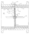
- FIG. 3 is a cross-sectional view in the III-III direction of FIG.
- FIG. 4 is a schematic diagram of an exhaust gas deadline method executed by the exhaust gas deadline controller.
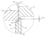
- FIG. 5 is an enlarged view in a circle V of FIG.
- FIG. 6 is an enlarged view of the vicinity of the valve seat when the exhaust gas of the exhaust gas cutoff control device is hot.
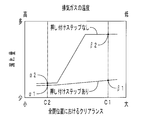
- FIG. 7 is a schematic diagram showing a difference in leakage amount with and without the pressing step.
- FIG. 8 is a schematic diagram of an exhaust gas deadline method executed by the exhaust gas deadline controller of the second embodiment.
- FIG. 1 shows a layout of the exhaust gas deadline control device of the present embodiment.
- FIG. 2 is a perspective view of the exhaust gas cutoff control device.
- FIG. 3 shows a cross-sectional view in the III-III direction of FIG. Note that FIG. 3 shows a low temperature when the temperature of the exhaust gas is low.
- a turbocharger 92 is disposed between the intake system 90 and the exhaust system 91.
- the exhaust gas cutoff control device 1 according to the present embodiment is disposed in a bypass pipe 910 that bypasses the turbocharger 92 in the exhaust system 91.
- the exhaust gas cutoff control device 1 mainly includes a housing 2, a butterfly valve 3, a motor 4, a control unit 5, a default spring 7, a link mechanism unit 8, It has.
- the motor 4 is included in the concept of the “actuator” of the present invention.
- the default spring 7 is included in the concept of the “opening direction biasing member” of the present invention.
- the housing 2 is disposed in a bypass pipe 910.
- the housing 2 includes an exhaust gas passage 20, a first sleeve 21, and a second sleeve 22.
- the first sleeve 21 and the second sleeve 22 are each made of stainless steel and have a cylindrical shape.
- the end surface in the axial direction of the first sleeve 21 and the end surface in the axial direction of the second sleeve 22 are abutted from the axial direction in a state of being radially displaced from each other.
- a valve seat 210 is set in a portion of the inner circumferential edge of the axial end face of the first sleeve 21 that is disposed radially inward from the inner circumferential edge of the axial end face of the second sleeve 22.
- a valve seat 220 is set in a portion of the inner circumferential edge of the axial end surface of the second sleeve 22 that is disposed radially inward of the inner circumferential edge of the axial end surface of the first sleeve 21.
- the exhaust gas passage 20 is disposed on the radially inner side of the first sleeve 21 and the second sleeve 22. The exhaust gas flows through the exhaust gas passage 20 from the first sleeve 21 toward the second sleeve 22.
- the butterfly valve 3 is disposed in the housing 2.
- the butterfly valve 3 can open and close the exhaust gas passage 20.
- the butterfly valve 3 includes a valve body 30 and a valve shaft 31.
- the valve shaft 31 is made of stainless steel and has a round bar shape.
- the valve body 30 is made of stainless steel and has a disk shape. A diameter portion of the valve body 30 is fixed to the valve shaft 31.
- the valve body 30 is rotatable inside the exhaust gas passage 20. The outer peripheral edge of the valve body 30 can be attached to and detached from the valve seats 210 and 220.
- valve shaft 31 protrudes outside the housing 2.
- the protruding portion of the valve shaft 31 is made of stainless steel and is rotatably supported inside a cylindrical valve shaft support boss 310.
- a cylindrical spacer 311 made of stainless steel is provided around the outer periphery of the valve shaft support boss 310.
- the default spring 7 is mounted on the outer peripheral surface of the spacer 311. That is, the spacer 311 prevents interference between the default spring 7 and the valve shaft support boss 310.
- One end of the default spring 7 is locked to a valve side arm 82 described later.
- the other end of the default spring 7 is locked to the housing 2.
- the default spring 7 biases the valve body of the butterfly valve 3 in the opening direction (the direction from the fully closed position P1 to the fully opened position P2 shown in FIG. 3).
- the motor 4 is connected to the butterfly valve 3 via a link mechanism portion 8 to be described later.
- the motor 4 includes a motor case 40 and a drive shaft 41.
- the motor case 40 houses a motor body (not shown).
- the drive shaft 41 protrudes from the motor case 40 to the outside.
- the drive shaft 41 and the motor body are connected by a speed reduction mechanism (not shown) including a plurality of gears.
- the link mechanism unit 8 includes a motor side arm 80, an intermediate arm 81, and a valve side arm 82.
- the link mechanism unit 8 has a folded scale shape (Z-shape) as a whole.
- the motor side arm 80 and the valve side arm 82 are each made of iron.
- the intermediate arm 81 is made of stainless steel.
- the motor side arm 80, the intermediate arm 81, and the valve side arm 82 each have a thin plate shape.
- One end of the motor side arm 80 is fixed to the drive shaft 41.
- the other end of the motor side arm 80 is swingably connected to one end of the intermediate arm 81.
- the other end of the intermediate arm 81 is swingably connected to one end of the valve side arm 82.
- the other end of the valve side arm 82 is fixed to one end of the valve shaft 31 passing through the valve shaft support boss 310.
- the control unit 5 is disposed integrally with the motor 4.
- the control unit 5 controls the drive of the motor 4.
- the control unit 5 includes a calculation unit 50 that is a CPU (central processing unit, microcomputer).
- the computing unit 50 includes a storage unit 51.
- the storage unit 51 is an EEPROM (electrically erasable programmable read-only memory).
- the storage unit 51 stores a fully closed position P1 and a fully open position P2 of the valve body 30 of the butterfly valve 3.
- the calculation unit 50 controls the motor 4 by PWM (Pulse-Width Modulation).
- PWM Pulse-Width Modulation
- the calculating part 50 can set the valve body 30 to a desired opening degree between the fully closed position P1 and the fully open position P2.
- the learning of the fully closed position P1 and the fully open position P2 is executed after the exhaust gas deadline control device 1 is assembled and before it is mounted on the vehicle. Specifically, first, a position learning unit (not shown) is connected to the control unit 5. Next, the butterfly valve 3 is actually driven by the control unit 5. Then, the fully closed position P1 (the opening degree of the valve body 30 where the passage cross-sectional area of the exhaust gas passage 20 is minimized during vehicle operation) and the fully open position P2 (the valve body where the passage cross-sectional area of the exhaust gas passage 20 is maximized during vehicle operation). 30 opening degree) and the storage unit 51. Finally, the position learning unit is removed from the control unit 5. The opening degree of the valve body 30 corresponding to the fully closed position P1 and the fully open position P2 varies depending on the engine and the vehicle type.
- ECU99 is connected to the control unit 5 as a high-order control apparatus.
- the control unit 5 controls the opening and closing of the butterfly valve 3 based on a control instruction from the ECU 99.
- FIG. 4 shows a schematic diagram of an exhaust gas deadline method executed by the exhaust gas deadline control apparatus of the present embodiment.
- the exhaust gas deadline method has a fully closed step and a pressing step.
- the motor 4 is fully closed from an arbitrary opening degree (specifically, an arbitrary opening degree between the fully opened position P2 and the fully closed position P1) as shown in FIG.
- the valve body 30 is rotated to the position P1.
- the calculating part 50 is carrying out duty ratio fluctuation
- the calculation unit 50 controls the motor 4 with a desired duty ratio.
- the calculation unit 50 once sets the duty ratio to zero.
- the motor 4 rotates the valve body 30 from the fully closed position P1 to the contact position P3 as shown in FIG. That is, in the rotation direction (opening / closing direction) of the valve body 30, the contact position P3 is set in the closing direction of the fully closed position P1 (the direction opposite to the fully opened position P2). Between the fully closed position P1 and the contact position P3, the calculation unit 50 controls the motor 4 to have a fixed duty ratio. For this reason, in the pressing step, the motor 4 rotates the valve body 30 with a constant pressing force F1.
- the pressing force F1 that is, the duty ratio in the duty ratio fixed control
- the duty ratio is stored in the storage unit 51 shown in FIG.
- FIG. 5 shows an enlarged view in the circle V of FIG.
- the valve body 30 is pressed against the valve seat 220 with a predetermined pressing force F1 at the contact position P3.
- the pressing force F1 is obtained when the ECU 99 shown in FIG. 1 issues a full-close instruction to the control unit 5 (or after the full-close instruction, the ECU 99 gives the next instruction to change the opening degree of the valve body 30).
- the motor 4 is continuously applied from the motor 4 to the valve body 30. For this reason, the amount of exhaust gas leakage from the upstream side (first sleeve 21 side) to the downstream side (second sleeve 22 side) is reduced.
- FIG. 6 shows an enlarged view of the vicinity of the valve seat when the exhaust gas of the exhaust gas cutoff control device of the present embodiment is high temperature.
- FIG. 6 corresponds to FIG.
- Fig. 7 is a schematic diagram showing the difference in leakage with and without the pressing step.
- ⁇ 1 shown in FIG. 7 corresponds to the case where the valve body 30 is in the contact position P3 at the high temperature shown in FIG.
- ⁇ 2 corresponds to the case where the valve body 30 is in the fully closed position P1 at the time of high temperature shown in FIG.
- ⁇ 1 corresponds to the case where the valve body 30 is in the contact position P3 at the low temperature shown in FIG.
- ⁇ 2 corresponds to the case where the valve body 30 is in the fully closed position P1 at the low temperature shown in FIG.
- the amount of leakage is reduced by executing the pressing step regardless of the temperature of the exhaust gas (regardless of the size of the clearance). Can do. In particular, when the temperature of the exhaust gas is low (when the clearance is large), the amount of leakage can be reduced.
- the motor 4 continuously pushes the valve body 30 after the valve body 30 exceeds the fully closed position P1. Pressure is being applied. For this reason, although the calculating part 50 shown in FIG. 1 cannot recognize the opening degree of the valve body 30, the valve body 30 can be reliably pressed on the valve seat 220. FIG.
- the exhaust gas cutoff control device 1 of this embodiment for example, based on the load current of the motor 4, the calculation unit 50 is compared with a case where it is determined whether or not the valve body 30 is seated on the valve seat 220.
- the circuit configuration of the exhaust gas cutoff control device 1 is simplified. For this reason, the manufacturing cost of the exhaust gas deadline control device 1 can be reduced.
- a default spring 7 is disposed in the exhaust gas cutoff control device 1 of the present embodiment.
- the default spring 7 always urges the valve body 30 in the opening direction. For this reason, even if the driving force is not transmitted from the motor 4 to the valve body 30, the valve body 30 can be set to the fully open position P2 shown in FIG. That is, the passage sectional area of the exhaust gas passage 20 can be maximized.
- the outer peripheral edge of the valve body 30 and the valve seat 220 are inclined in the same direction with respect to the radial direction of the valve body 30. ing. For this reason, even if the valve body 30 is thermally expanded radially outward, the outer peripheral edge of the valve body 30 can slide along the surface direction of the valve seat 220. Therefore, the outer peripheral edge of the valve body 30 is difficult to bite into the valve seat 220.
- FIG. 8 shows a schematic diagram of an exhaust gas deadline method executed by the exhaust gas deadline control apparatus of the present embodiment.
- part corresponding to FIG. 4 it shows with the same code
- the calculation unit does not set the duty ratio to zero.
- the calculation unit starts the duty ratio fixing control before the valve body arrives at the fully closed position P1.
- the exhaust gas deadline control device and the exhaust gas deadline control device according to the first embodiment have the same functions and effects with respect to parts having the same configuration.
- the duty ratio need not be reduced to 0 at the fully closed position P1. That is, it is only necessary that the duty ratio fixing control is executed at least in the section from the fully closed position P1 to the contact position P3 (during the pressing step).
- the type of valve is not limited to butterfly valve 3.
- a poppet valve may be used.
- the location of the exhaust gas deadline control device 1 is not particularly limited. You may arrange
- the magnitude of the pressing force F1 applied to the valve body 30 by the motor 4 at the contact position P3 is not particularly limited. It is only necessary that the rotational torque in the direction toward the valve seat 220 can be transmitted to the valve body 30.
- the default spring 7 is disposed as an example of the “opening direction biasing member” of the present invention.
- a return spring may be disposed as an example of the “closing direction biasing member” of the present invention.
- the default spring 7 and the return spring may be used in combination.
Landscapes
- Engineering & Computer Science (AREA)
- General Engineering & Computer Science (AREA)
- Mechanical Engineering (AREA)
- Chemical & Material Sciences (AREA)
- Combustion & Propulsion (AREA)
- Lift Valve (AREA)
- Electrically Driven Valve-Operating Means (AREA)
- Exhaust-Gas Circulating Devices (AREA)
Abstract
全閉制御時に、弁体と弁座との間のクリアランスから、排気ガスが漏出しにくい排気ガス締め切り制御装置を提供することを課題とする。 排気ガス締め切り制御装置(1)は、弁体(30)を有するバルブ(3)と、弁座(220)を有する排ガス通路(20)が形成されたハウジング(2)と、弁体(30)を駆動するアクチュエータ(4)と、全開位置(P2)と全閉位置(P1)とが予め記憶された記憶部(51)と、アクチュエータ(4)を制御することにより、任意の位置から全閉位置(P1)に弁体(30)を切り替える全閉ステップを実行する演算部(50)と、を有する制御ユニット(5)と、を備える。弁体(30)が弁座(220)に着座する弁体(30)の位置を当接位置(P3)として、演算部(50)は、全閉ステップの後に、全閉位置(P1)から当接位置(P3)まで弁体(30)を移動させ、所定の押圧力(F1)で弁体(30)を弁座(220)に押し付ける押し付けステップを実行することを特徴とする。
Description
本発明は、例えば、ターボシステム、排気ガス再循環システム(EGRシステム)、排気ブレーキシステムなどに用いられる排気ガス締め切り制御装置に関する。
特許文献1には、EGRシステムに用いられるバルブアセンブリが開示されている。同文献記載のバルブアセンブリによると、ガス通路を通過する排気ガスの流量を調整することができる。すなわち、バルブアセンブリは、バタフライバルブを備えている。バタフライバルブの弁体は、排気ガスの流量が最小となる全閉位置と、排気ガスの流量が最大となる全開位置と、の間で回動可能である。バルブアセンブリは、弁体を所定の位置にセットすることにより、排気ガスの流量を調整している。
ところで、ガス通路を流れる排気ガスの温度が変化する場合、排気ガスの流れが衝突する弁体の温度も変化する。並びに、ガス通路に形成された弁座の温度も変化する。弁体と弁座とを比較すると、排気ガスの流れに正対している弁体の方が、弁座よりも、温度変化が大きい。このため、弁体の方が、弁座よりも、熱変形量が大きくなる。
ここで、低温時を基準に弁体、弁座を設計する場合、高温時において弁体が弁座に過度に圧接しやすくなる。すなわち、弁座に対して、弁体の方が、熱膨張量が大きい。このため、低温時の全閉位置において弁体が弁座に着座するように弁体、弁座を設計する場合、高温時において弁体が弁座に過度に圧接しやすくなる。したがって、高温時において、全閉位置から別の位置に、弁体を移動させにくくなる。
これに対して、高温時を基準に弁体、弁座を設計する場合、低温時において弁体と弁座との間にクリアランスが発生してしまう。このため、高温時の全閉位置において弁体が弁座に着座するように弁体、弁座を設計する場合、低温時において弁体が弁座から離間してしまう。したがって、低温時において、全閉位置であるにもかかわらず、弁体と弁座との間にクリアランスが発生してしまう。よって、弁体の上流側から下流側に排気ガスが漏出してしまう。
このように、低温時を基準に弁体、弁座を設計しても、高温時を基準に弁体、弁座を設計しても、デメリットが発生してしまう。しかしながら、弁体の円滑な動作を確保するためには、低温時かつ全閉位置における排気ガスの漏出を敢えて許容し、高温時を基準に弁体、弁座を設計する必要がある。
特許文献2には、EGRシステムに用いられるバルブ開閉制御装置が開示されている。同文献記載のバルブ開閉制御装置によると、バルブを全閉位置に切り替える際に、全閉位置の手前(全開位置側)に設定された制御上の全閉ポイントで、バルブを停止させることができる。特許文献2には、上記課題(低温時かつ全閉位置におけるクリアランスからの排気ガスの漏出という課題)は、開示、示唆されていない。
そこで、本発明は、全閉制御時に、弁体と弁座との間のクリアランスから、排気ガスが漏出しにくい排気ガス締め切り制御装置を提供することを目的とする。
(1)上記課題を解決するため、本発明の排気ガス締め切り制御装置は、弁体を有するバルブと、該弁体が離着可能な弁座を有する排ガス通路が形成されたハウジングと、該弁体を駆動するアクチュエータと、該排ガス通路の通路断面積が最大となる該弁体の位置である全開位置と、該全開位置よりも該通路断面積が小さくなる該弁体の位置である全閉位置と、が予め記憶された記憶部と、該アクチュエータを制御することにより、任意の位置から該全閉位置に該弁体を切り替える全閉ステップを実行する演算部と、を有する制御ユニットと、を備える排気ガス締め切り制御装置であって、前記弁体が前記弁座に着座する該弁体の位置を当接位置として、前記演算部は、前記全閉ステップの後に、前記全閉位置から該当接位置まで該弁体を移動させ、所定の押圧力で該弁体を該弁座に押し付ける押し付けステップを実行することを特徴とする。ここで、「通路断面積」とは、排ガス通路の延在方向に対して、直交する方向の断面積をいう。
本発明の排気ガス締め切り制御装置によると、演算部が、全閉ステップと、押し付けステップと、を実行する。全閉ステップにおいては、アクチュエータは、任意の位置から全閉位置まで弁体を移動させる。押し付けステップにおいては、アクチュエータは、全閉位置から当接位置まで弁体を移動させる。当接位置においては、弁体が弁座に押し付けられる。このため、全閉制御時(例えば、ECU(Engine Control Unit)などの上位制御装置から、制御ユニットに、全閉指示が出された場合)に、弁体と弁座との間のクリアランスから、排気ガスが漏出するのを抑制することができる。
(1-1)好ましくは、上記(1)の構成において、前記バルブはバタフライバルブである構成とする方がよい。バタフライバルブは、弁軸と弁体とを備えている。弁体は、弁軸の軸周りに回転する。本構成によると、当接位置において、弁体の外周縁のうち、弁軸の径方向外端部分を、弁座に押し付けることができる。
(2)好ましくは、上記(1)の構成において、前記記憶部は、前記当接位置を記憶せず、前記演算部は、前記押し付けステップにおいて、前記押圧力を前記弁体に加え続ける構成とする方がよい。
記憶部には、予め、全開位置と全閉位置とが記憶されている。全閉ステップにおいて、演算部は、弁体の位置を認識することができる。一方、記憶部には、当接位置が記憶されていない。このため、押し付けステップにおいて、演算部は、弁体の位置を認識することができない。つまり、演算部は、弁体が当接位置に到着したか否か(弁体が弁座に着座したか否か)を判別することができない。
この点、本構成の場合、押し付けステップにおいて、アクチュエータが弁体に継続的に押圧力を加えている。このため、演算部が弁体の位置を認識することができないにもかかわらず、確実に、弁体を弁座に押し付けることができる。
本構成によると、例えばアクチュエータの負荷(負荷電流、負荷電圧など)を基に、演算部が、弁体が弁座に着座したか否かを判別する場合(この場合も、勿論、上記(1)の構成に含まれる。)と比較して、排気ガス締め切り制御装置の回路構成が簡単になる。このため、排気ガス締め切り制御装置の製造コストを削減することができる。
(3)好ましくは、上記(1)または(2)の構成において、さらに、前記全閉位置から前記全開位置に向かう方向に、前記弁体に付勢力を加える開方向付勢部材を備える構成とする方がよい。
本発明の排気ガス締め切り装置が用いられるシステムによっては、フェイルセーフの観点から、故障時などに排ガス通路の通路断面積が最大になる方が好ましい場合がある。この点、本構成の排気ガス締め切り装置は、開方向付勢部材を備えている。開方向付勢部材は、常時、弁体を、開方向に付勢している。このため、アクチュエータから弁体に駆動力が伝達されなくなっても、開方向付勢部材の付勢力により、弁体を全開位置に設定することができる。つまり、排ガス通路の通路断面積を最大にすることができる。
また、押し付けステップにおいてアクチュエータが弁体に加える押圧力は、付勢力に対して、反対方向に作用する。本構成によると、当接位置において、付勢力に抗して、弁体を弁座に押し付けることができる。
(4)好ましくは、上記(1)ないし(3)のいずれかの構成において、さらに、前記全開位置から前記全閉位置に向かう方向に、前記弁体に付勢力を加える閉方向付勢部材を備える構成とする方がよい。
閉方向付勢部材は、常時、弁体を、閉方向に付勢している。押し付けステップにおいてアクチュエータが弁体に加える押圧力は、閉方向付勢部材の付勢力と同じ方向に作用する。本構成によると、当接位置において、当該付勢力と押圧力とにより、弁体を弁座に押し付けることができる。
本発明によると、全閉制御時に、弁体と弁座との間のクリアランスから、排気ガスが漏出しにくい排気ガス締め切り制御装置を提供することができる。
以下、本発明の排気ガス締め切り制御装置の実施の形態について説明する。
<第一実施形態>
[排気ガス締め切り制御装置の構成]
まず、本実施形態の排気ガス締め切り制御装置の構成について説明する。図1に、本実施形態の排気ガス締め切り制御装置の配置図を示す。図2に、同排気ガス締め切り制御装置の斜視図を示す。図3に、図2のIII-III方向断面図を示す。なお、図3に示すのは、排気ガスの温度が低い低温時である。
[排気ガス締め切り制御装置の構成]
まず、本実施形態の排気ガス締め切り制御装置の構成について説明する。図1に、本実施形態の排気ガス締め切り制御装置の配置図を示す。図2に、同排気ガス締め切り制御装置の斜視図を示す。図3に、図2のIII-III方向断面図を示す。なお、図3に示すのは、排気ガスの温度が低い低温時である。
図1に示すように、吸気系90と排気系91との間には、ターボチャージャー92が配置されている。本実施形態の排気ガス締め切り制御装置1は、排気系91においてターボチャージャー92を迂回する、バイパス配管910に配置されている。
図1~図3に示すように、排気ガス締め切り制御装置1は、主に、ハウジング2と、バタフライバルブ3と、モータ4と、制御ユニット5と、デフォルトスプリング7と、リンク機構部8と、を備えている。モータ4は、本発明の「アクチュエータ」の概念に含まれる。デフォルトスプリング7は、本発明の「開方向付勢部材」の概念に含まれる。
(ハウジング2)
図1に示すように、ハウジング2は、バイパス配管910に配置されている。図3に示すように、ハウジング2は、排ガス通路20と、第一スリーブ21と、第二スリーブ22と、を備えている。第一スリーブ21、第二スリーブ22は、各々、ステンレス鋼製であって、円筒状を呈している。第一スリーブ21の軸方向端面と第二スリーブ22の軸方向端面とは、互いに径方向にずれた状態で、軸方向から突き合わされている。
図1に示すように、ハウジング2は、バイパス配管910に配置されている。図3に示すように、ハウジング2は、排ガス通路20と、第一スリーブ21と、第二スリーブ22と、を備えている。第一スリーブ21、第二スリーブ22は、各々、ステンレス鋼製であって、円筒状を呈している。第一スリーブ21の軸方向端面と第二スリーブ22の軸方向端面とは、互いに径方向にずれた状態で、軸方向から突き合わされている。
第一スリーブ21の軸方向端面の内周縁のうち、第二スリーブ22の軸方向端面の内周縁よりも、径方向内側に配置されている部分には、弁座210が設定されている。同様に、第二スリーブ22の軸方向端面の内周縁のうち、第一スリーブ21の軸方向端面の内周縁よりも、径方向内側に配置されている部分には、弁座220が設定されている。排ガス通路20は、第一スリーブ21および第二スリーブ22の径方向内側に配置されている。排気ガスは、排ガス通路20を、第一スリーブ21から第二スリーブ22に向かって、流動する。
(バタフライバルブ3)
バタフライバルブ3は、ハウジング2に配置されている。バタフライバルブ3は、排ガス通路20を開閉可能である。バタフライバルブ3は、弁体30と弁軸31とを備えている。弁軸31は、ステンレス鋼製であって、丸棒状を呈している。弁体30は、ステンレス鋼製であって、円板状を呈している。弁体30の直径部分は、弁軸31に固定されている。弁体30は、排ガス通路20の内部において、回転可能である。弁体30の外周縁は、弁座210、220に対して、離着可能である。
バタフライバルブ3は、ハウジング2に配置されている。バタフライバルブ3は、排ガス通路20を開閉可能である。バタフライバルブ3は、弁体30と弁軸31とを備えている。弁軸31は、ステンレス鋼製であって、丸棒状を呈している。弁体30は、ステンレス鋼製であって、円板状を呈している。弁体30の直径部分は、弁軸31に固定されている。弁体30は、排ガス通路20の内部において、回転可能である。弁体30の外周縁は、弁座210、220に対して、離着可能である。
図2に示すように、弁軸31の一端は、ハウジング2の外部に突出している。弁軸31の当該突出部分は、ステンレス鋼製であって円筒状の弁軸支持ボス310の内部に、回転可能に支持されている。弁軸支持ボス310の外周側には、ステンレス鋼製であって円筒状のスペーサ311が環装されている。デフォルトスプリング7は、スペーサ311の外周面に環装されている。すなわち、スペーサ311は、デフォルトスプリング7と弁軸支持ボス310との干渉を防止している。デフォルトスプリング7の一端は、後述するバルブ側アーム82に係止されている。デフォルトスプリング7の他端は、ハウジング2に係止されている。デフォルトスプリング7は、バタフライバルブ3の弁体を開方向(図3に示す全閉位置P1から全開位置P2に向かう方向)に付勢している。
(モータ4)
モータ4は、後述するリンク機構部8を介して、バタフライバルブ3に連結されている。モータ4は、モータケース40と、駆動軸41と、を備えている。モータケース40には、モータ本体(図略)が収容されている。駆動軸41は、モータケース40から、外部に突出している。駆動軸41とモータ本体とは、複数のギアからなる減速機構部(図略)により、連結されている。
モータ4は、後述するリンク機構部8を介して、バタフライバルブ3に連結されている。モータ4は、モータケース40と、駆動軸41と、を備えている。モータケース40には、モータ本体(図略)が収容されている。駆動軸41は、モータケース40から、外部に突出している。駆動軸41とモータ本体とは、複数のギアからなる減速機構部(図略)により、連結されている。
(リンク機構部8)
リンク機構部8は、モータ側アーム80と、中間アーム81と、バルブ側アーム82と、を備えている。リンク機構部8は、全体として折れ尺状(Z字状)を呈している。モータ側アーム80およびバルブ側アーム82は、各々、鉄製である。これに対して、中間アーム81は、ステンレス鋼製である。モータ側アーム80および中間アーム81およびバルブ側アーム82は、各々、細板状を呈している。
リンク機構部8は、モータ側アーム80と、中間アーム81と、バルブ側アーム82と、を備えている。リンク機構部8は、全体として折れ尺状(Z字状)を呈している。モータ側アーム80およびバルブ側アーム82は、各々、鉄製である。これに対して、中間アーム81は、ステンレス鋼製である。モータ側アーム80および中間アーム81およびバルブ側アーム82は、各々、細板状を呈している。
モータ側アーム80の一端は、駆動軸41に固定されている。モータ側アーム80の他端は、中間アーム81の一端に、揺動可能に接続されている。中間アーム81の他端は、バルブ側アーム82の一端に、揺動可能に接続されている。バルブ側アーム82の他端は、弁軸支持ボス310を貫通した弁軸31の一端に、固定されている。
(制御ユニット5)
制御ユニット5は、モータ4と一体に配置されている。制御ユニット5は、モータ4を駆動制御している。図1に示すように、制御ユニット5は、CPU(central processing unit、マイコン)である演算部50を備えている。演算部50には、記憶部51が内蔵されている。記憶部51は、EEPROM(electrically erasable programmable read-only memory)である。記憶部51には、バタフライバルブ3の弁体30の全閉位置P1と全開位置P2とが格納されている。
制御ユニット5は、モータ4と一体に配置されている。制御ユニット5は、モータ4を駆動制御している。図1に示すように、制御ユニット5は、CPU(central processing unit、マイコン)である演算部50を備えている。演算部50には、記憶部51が内蔵されている。記憶部51は、EEPROM(electrically erasable programmable read-only memory)である。記憶部51には、バタフライバルブ3の弁体30の全閉位置P1と全開位置P2とが格納されている。
演算部50は、モータ4をPWM(Pulse-Width Modulation)制御している。演算部50は、全閉位置P1と全開位置P2との間において、弁体30を所望の開度にセット可能である。
全閉位置P1、全開位置P2の学習は、排気ガス締め切り制御装置1を組み立ててから車両に搭載する前までの間に、実行される。具体的には、まず、制御ユニット5に位置学習ユニット(図略)を接続する。次に、制御ユニット5により、実際にバタフライバルブ3を駆動する。それから、全閉位置P1(車両運転時に排ガス通路20の通路断面積が最小になる弁体30の開度)と、全開位置P2(車両運転時に排ガス通路20の通路断面積が最大になる弁体30の開度)と、を記憶部51に格納する。最後に、制御ユニット5から位置学習ユニットを取り外す。なお、全閉位置P1、全開位置P2に対応する弁体30の開度は、エンジンや車種により様々である。
制御ユニット5には、上位制御装置として、ECU99が接続されている。制御ユニット5は、ECU99からの制御指示に基づいて、バタフライバルブ3を開閉制御している。
[排気ガス締め切り方法]
次に、本実施形態の排気ガス締め切り制御装置1が実行する排気ガス締め切り方法について説明する。図4に、本実施形態の排気ガス締め切り制御装置が実行する排気ガス締め切り方法の模式図を示す。図1に示すECU99から制御ユニット5に全閉指示(弁体30を全閉位置P1まで回動させる指示)が出されると、演算部50は排気ガス締め切り方法を実行する。
次に、本実施形態の排気ガス締め切り制御装置1が実行する排気ガス締め切り方法について説明する。図4に、本実施形態の排気ガス締め切り制御装置が実行する排気ガス締め切り方法の模式図を示す。図1に示すECU99から制御ユニット5に全閉指示(弁体30を全閉位置P1まで回動させる指示)が出されると、演算部50は排気ガス締め切り方法を実行する。
まず、排気ガスが低温の場合について説明する。排気ガス締め切り方法は、全閉ステップと、押し付けステップと、を有している。全閉ステップにおいては、モータ4が、図3に示すように、任意の開度(具体的には、全開位置P2と、全閉位置P1と、の間の任意の開度)から、全閉位置P1まで、弁体30を回動させる。図4に示すように、全開位置P2と全閉位置P1との間においては、演算部50は、モータ4を、デューティー比変動制御している。なお、デューティー比とは、モータ4に対する駆動信号のパルス波のパルス幅をτ、周期をTとして、デューティー比(%)=τ/T×100という式から算出される。このため、全閉ステップにおいては、演算部50は、所望のデューティー比で、モータ4を制御する。弁体30が全閉位置P1に到着すると、演算部50は、一旦、デューティー比を0にする。
押し付けステップにおいては、モータ4が、図3に示すように、全閉位置P1から、当接位置P3まで、弁体30を回動させる。すなわち、弁体30の回転方向(開閉方向)において、全閉位置P1の閉方向(全開位置P2と反対方向)には、当接位置P3が設定されている。全閉位置P1から当接位置P3までの間においては、演算部50は、モータ4を、デューティー比固定制御している。このため、押し付けステップにおいては、モータ4は弁体30を一定の押圧力F1で回動させる。なお、当該押圧力F1、つまりデューティー比固定制御におけるデューティー比は、モータ4の発熱量、リンク機構部8や減速機構部のギアの損傷、デフォルトスプリング7の開方向の付勢力F2などを考慮して、予め設定されている。当該デューティー比は、図1に示す記憶部51に格納されている。
図5に、図3の円V内の拡大図を示す。図3、図5に示すように、当接位置P3においては、弁体30が弁座220に、所定の押圧力F1で押し付けられている。押圧力F1は、図1に示すECU99が制御ユニット5に全閉指示を出している間(または、当該全閉指示の後、弁体30の開度を変える次の指示を、ECU99が制御ユニット5に出すまでの間)、継続的にモータ4から弁体30に加えられる。このため、上流側(第一スリーブ21側)から下流側(第二スリーブ22側)への排気ガスの漏れ量が少なくなる。
なお、図5に一点鎖線で示すように、弁体30が全閉位置P1に到達しても、弁体30と弁座220との間には、径方向にクリアランスC1が存在している。ここで、弁体30、弁座220は、排気ガスの温度が高温の場合を基準に、設計されている。このため、低温時におけるクリアランスC1は、比較的大きい。したがって、仮に押し付けステップを実行しない場合、弁体30は全閉位置P1で停止するため、上流側から下流側への排気ガスの漏れ量が多くなる。
次に、排気ガスが高温の場合について説明する。排気ガスが高温の場合も、排気ガスが低温の場合と同様である。図6に、本実施形態の排気ガス締め切り制御装置の排気ガスが高温の場合の弁座付近の拡大図を示す。なお、図6は、図5に対応している。
図6に示すように、排気ガスが高温の場合、弁体30が径方向外側に熱膨張してしまう。このため、排気ガスが低温の場合と比較して、全閉位置P1におけるクリアランスC2が小さくなる。すなわち、C2<C1となる。この場合であっても、押し付けステップにおいて、弁体30を当接位置P3まで回動させるため、上流側から下流側への排気ガスの漏れ量が少なくなる。
[排気ガス締め切り制御装置の作用効果]
次に、本実施形態の排気ガス締め切り制御装置1の作用効果について説明する。本実施形態の排気ガス締め切り制御装置1によると、図1に示すECU99が制御ユニット5に全閉指示を出すと、図4に示すように、モータ4は、全閉指示が出た時点の弁体30の位置から、当接位置P3まで、弁体30を回動させる。図3に示すように、モータ4は、全閉指示が出ている間、継続的に所定の押圧力F1で弁体30を弁座220に押し付ける。このため、図1に示すECU99が全閉指示を出した場合、図5、図6に示すように、弁体30と弁座220との間のクリアランスC1、C2から、排気ガスが漏出するのを抑制することができる。
次に、本実施形態の排気ガス締め切り制御装置1の作用効果について説明する。本実施形態の排気ガス締め切り制御装置1によると、図1に示すECU99が制御ユニット5に全閉指示を出すと、図4に示すように、モータ4は、全閉指示が出た時点の弁体30の位置から、当接位置P3まで、弁体30を回動させる。図3に示すように、モータ4は、全閉指示が出ている間、継続的に所定の押圧力F1で弁体30を弁座220に押し付ける。このため、図1に示すECU99が全閉指示を出した場合、図5、図6に示すように、弁体30と弁座220との間のクリアランスC1、C2から、排気ガスが漏出するのを抑制することができる。
図7に、押し付けステップの有無における漏れ量の違いを模式図で示す。図7に示すα1は、図6に示す高温時において、弁体30が当接位置P3にある場合に対応している。α2は、図6に示す高温時において、弁体30が全閉位置P1にある場合に対応している。β1は、図5に示す低温時において、弁体30が当接位置P3にある場合に対応している。β2は、図5に示す低温時において、弁体30が全閉位置P1にある場合に対応している。
図7に示すように、押し付けステップを実行しない場合と比較して、押し付けステップを実行する方が、排気ガスの温度の高低によらず(クリアランスの大小によらず)、漏れ量を少なくすることができる。特に、排気ガスの温度が低い場合に(クリアランスが大きい場合に)、漏れ量を少なくすることができる。
また、本実施形態の排気ガス締め切り制御装置1によると、図3、図4に示すように、弁体30が全閉位置P1を超えた後は、モータ4が弁体30に継続的に押圧力を加えている。このため、図1に示す演算部50が弁体30の開度を認識することができないにもかかわらず、確実に、弁体30を弁座220に押し付けることができる。
また、本実施形態の排気ガス締め切り制御装置1によると、例えばモータ4の負荷電流を基に、演算部50が、弁体30が弁座220に着座したか否かを判別する場合と比較して、排気ガス締め切り制御装置1の回路構成が簡単になる。このため、排気ガス締め切り制御装置1の製造コストを削減することができる。
また、本実施形態の排気ガス締め切り制御装置1には、図2に示すように、デフォルトスプリング7が配置されている。デフォルトスプリング7は、常時、開方向に弁体30を付勢している。このため、モータ4から弁体30に駆動力が伝達されなくなっても、デフォルトスプリング7の付勢力により、弁体30を図3に示す全開位置P2に設定することができる。つまり、排ガス通路20の通路断面積を最大にすることができる。
また、本実施形態の排気ガス締め切り制御装置1によると、図6に示すように、弁体30の外周縁と弁座220とが、弁体30の径方向に対して、同じ方向に傾斜している。このため、弁体30が径方向外側に熱膨張しても、弁体30の外周縁が、弁座220の面方向に沿って、摺動することができる。したがって、弁体30の外周縁が、弁座220に噛み込みにくい。
<第二実施形態>
本実施形態の排気ガス締め切り制御装置と、第一実施形態の排気ガス締め切り制御装置との相違点は、排気ガス締め切り方法実行時のデューティー比の設定のみである。ここでは、相違点についてのみ説明する。
本実施形態の排気ガス締め切り制御装置と、第一実施形態の排気ガス締め切り制御装置との相違点は、排気ガス締め切り方法実行時のデューティー比の設定のみである。ここでは、相違点についてのみ説明する。
図8に、本実施形態の排気ガス締め切り制御装置が実行する排気ガス締め切り方法の模式図を示す。なお、図4と対応する部位については、同じ符号で示す。図8に示すように、弁体が全閉位置P1に到着しても、演算部は、デューティー比を0にしない。演算部は、弁体が全閉位置P1に到着する前に、デューティー比固定制御を開始している。
本実施形態の排気ガス締め切り制御装置と、第一実施形態の排気ガス締め切り制御装置とは、構成が共通する部分に関しては、同様の作用効果を有する。本実施形態のように、全閉位置P1において、デューティー比を0まで下げなくてもよい。すなわち、少なくとも全閉位置P1から当接位置P3までの区間において(押し付けステップ中において)、デューティー比固定制御が実行されていればよい。
<その他>
以上、本発明の排気ガス締め切り制御装置の実施の形態について説明した。しかしながら、実施の形態は上記形態に特に限定されるものではない。当業者が行いうる種々の変形的形態、改良的形態で実施することも可能である。
以上、本発明の排気ガス締め切り制御装置の実施の形態について説明した。しかしながら、実施の形態は上記形態に特に限定されるものではない。当業者が行いうる種々の変形的形態、改良的形態で実施することも可能である。
バルブの種類はバタフライバルブ3に限定しない。例えば、ポペットバルブなどであってもよい。排気ガス締め切り制御装置1の配置場所は特に限定しない。EGRシステム、排気ブレーキシステムなどに配置してもよい。図3に示すように、当接位置P3においてモータ4が弁体30に加える押圧力F1の大きさは、特に限定しない。弁座220に向かう方向の回転トルクを弁体30に伝達できればよい。
上記実施形態においては、本発明の「開方向付勢部材」の一例として、デフォルトスプリング7を配置した。しかしながら、デフォルトスプリング7の代わりに、本発明の「閉方向付勢部材」の一例として、リターンスプリングを配置してもよい。また、デフォルトスプリング7と、リターンスプリングと、を併用してもよい。
1:排気ガス締め切り制御装置。
2:ハウジング、20:排ガス通路、21:第一スリーブ、210:弁座、22:第二スリーブ、220:弁座。
3:バタフライバルブ、30:弁体、31:弁軸、310:弁軸支持ボス、311:スペーサ。
4:モータ(アクチュエータ)、40:モータケース、41:駆動軸。
5:制御ユニット、50:演算部、51:記憶部。
7:デフォルトスプリング(開方向付勢部材)。
8:リンク機構部、80:モータ側アーム、81:中間アーム、82:バルブ側アーム。
90:吸気系、91:排気系、910:バイパス配管、92:ターボチャージャー、99:ECU。
C1:クリアランス、C2:クリアランス、F1:押圧力、F2:付勢力、P1:全閉位置、P2:全開位置、P3:当接位置。
2:ハウジング、20:排ガス通路、21:第一スリーブ、210:弁座、22:第二スリーブ、220:弁座。
3:バタフライバルブ、30:弁体、31:弁軸、310:弁軸支持ボス、311:スペーサ。
4:モータ(アクチュエータ)、40:モータケース、41:駆動軸。
5:制御ユニット、50:演算部、51:記憶部。
7:デフォルトスプリング(開方向付勢部材)。
8:リンク機構部、80:モータ側アーム、81:中間アーム、82:バルブ側アーム。
90:吸気系、91:排気系、910:バイパス配管、92:ターボチャージャー、99:ECU。
C1:クリアランス、C2:クリアランス、F1:押圧力、F2:付勢力、P1:全閉位置、P2:全開位置、P3:当接位置。
Claims (4)
- 弁体を有するバルブと、
該弁体が離着可能な弁座を有する排ガス通路が形成されたハウジングと、
該弁体を駆動するアクチュエータと、
該排ガス通路の通路断面積が最大となる該弁体の位置である全開位置と、該全開位置よりも該通路断面積が小さくなる該弁体の位置である全閉位置と、が予め記憶された記憶部と、該アクチュエータを制御することにより、任意の位置から該全閉位置に該弁体を切り替える全閉ステップを実行する演算部と、を有する制御ユニットと、
を備える排気ガス締め切り制御装置であって、
前記弁体が前記弁座に着座する該弁体の位置を当接位置として、
前記演算部は、前記全閉ステップの後に、前記全閉位置から該当接位置まで該弁体を移動させ、所定の押圧力で該弁体を該弁座に押し付ける押し付けステップを実行することを特徴とする排気ガス締め切り制御装置。 - 前記記憶部は、前記当接位置を記憶せず、
前記演算部は、前記押し付けステップにおいて、前記押圧力を前記弁体に加え続ける請求項1に記載の排気ガス締め切り制御装置。 - さらに、前記全閉位置から前記全開位置に向かう方向に、前記弁体に付勢力を加える開方向付勢部材を備える請求項1または請求項2に記載の排気ガス締め切り制御装置。
- さらに、前記全開位置から前記全閉位置に向かう方向に、前記弁体に付勢力を加える閉方向付勢部材を備える請求項1ないし請求項3のいずれかに記載の排気ガス締め切り制御装置。
Applications Claiming Priority (2)
| Application Number | Priority Date | Filing Date | Title |
|---|---|---|---|
| JP2012-241018 | 2012-10-31 | ||
| JP2012241018A JP5925664B2 (ja) | 2012-10-31 | 2012-10-31 | 排気ガス締め切り制御装置 |
Publications (1)
| Publication Number | Publication Date |
|---|---|
| WO2014069465A1 true WO2014069465A1 (ja) | 2014-05-08 |
Family
ID=50627367
Family Applications (1)
| Application Number | Title | Priority Date | Filing Date |
|---|---|---|---|
| PCT/JP2013/079287 Ceased WO2014069465A1 (ja) | 2012-10-31 | 2013-10-29 | 排気ガス締め切り制御装置 |
Country Status (2)
| Country | Link |
|---|---|
| JP (1) | JP5925664B2 (ja) |
| WO (1) | WO2014069465A1 (ja) |
Cited By (1)
| Publication number | Priority date | Publication date | Assignee | Title |
|---|---|---|---|---|
| JP2021173370A (ja) * | 2020-04-28 | 2021-11-01 | 株式会社テージーケー | バタフライバルブ、その制御装置および制御方法 |
Citations (5)
| Publication number | Priority date | Publication date | Assignee | Title |
|---|---|---|---|---|
| JP2001271955A (ja) * | 2000-03-28 | 2001-10-05 | Tgk Co Ltd | 電動バタフライバルブ |
| WO2003026123A1 (en) * | 2001-09-17 | 2003-03-27 | Mitsubishi Denki Kabushiki Kaisha | Brake for dc motor |
| JP2004263723A (ja) * | 2003-02-13 | 2004-09-24 | Taiho Kogyo Co Ltd | 流量制御バルブ |
| JP2007083856A (ja) * | 2005-09-21 | 2007-04-05 | Honda Motor Co Ltd | 低床式の自動二輪車 |
| JP2007285123A (ja) * | 2006-04-12 | 2007-11-01 | Denso Corp | バルブ開閉制御装置 |
Family Cites Families (1)
| Publication number | Priority date | Publication date | Assignee | Title |
|---|---|---|---|---|
| JPH05106752A (ja) * | 1991-10-17 | 1993-04-27 | Honda Motor Co Ltd | バルブシステム |
-
2012
- 2012-10-31 JP JP2012241018A patent/JP5925664B2/ja active Active
-
2013
- 2013-10-29 WO PCT/JP2013/079287 patent/WO2014069465A1/ja not_active Ceased
Patent Citations (5)
| Publication number | Priority date | Publication date | Assignee | Title |
|---|---|---|---|---|
| JP2001271955A (ja) * | 2000-03-28 | 2001-10-05 | Tgk Co Ltd | 電動バタフライバルブ |
| WO2003026123A1 (en) * | 2001-09-17 | 2003-03-27 | Mitsubishi Denki Kabushiki Kaisha | Brake for dc motor |
| JP2004263723A (ja) * | 2003-02-13 | 2004-09-24 | Taiho Kogyo Co Ltd | 流量制御バルブ |
| JP2007083856A (ja) * | 2005-09-21 | 2007-04-05 | Honda Motor Co Ltd | 低床式の自動二輪車 |
| JP2007285123A (ja) * | 2006-04-12 | 2007-11-01 | Denso Corp | バルブ開閉制御装置 |
Cited By (2)
| Publication number | Priority date | Publication date | Assignee | Title |
|---|---|---|---|---|
| JP2021173370A (ja) * | 2020-04-28 | 2021-11-01 | 株式会社テージーケー | バタフライバルブ、その制御装置および制御方法 |
| JP7386529B2 (ja) | 2020-04-28 | 2023-11-27 | 株式会社テージーケー | バタフライバルブ、その制御装置および制御方法 |
Also Published As
| Publication number | Publication date |
|---|---|
| JP2014092034A (ja) | 2014-05-19 |
| JP5925664B2 (ja) | 2016-05-25 |
Similar Documents
| Publication | Publication Date | Title |
|---|---|---|
| JP5086338B2 (ja) | 共通の駆動モータによって駆動される二重バタフライバルブ | |
| JP5510428B2 (ja) | 低圧egr装置 | |
| JP6283669B2 (ja) | 排気ガスターボチャージャ | |
| JP5925604B2 (ja) | 冷却水制御弁 | |
| CN101413420B (zh) | 用于发动机系统的压力平衡回转阀 | |
| JP5673602B2 (ja) | バルブ装置 | |
| JP2011513620A (ja) | ウェイストゲートダクトの開放及び閉鎖のための操作装置を備えたターボチャージャ | |
| JP5355792B2 (ja) | ステップタイプバルブ | |
| US9726074B2 (en) | Turbocharger integrated valve unit | |
| JP6157500B2 (ja) | 自動車エンジン用の安全ダブルチャネル制御装置 | |
| WO2013176158A1 (ja) | ロータリ式バルブ | |
| JPWO2012131777A1 (ja) | バタフライバルブ | |
| JP2016505781A (ja) | 直列に配置されるとともに共通のモータにより作動される2つのフラップを備えた弁 | |
| US20080116404A1 (en) | Hybrid exhaust valve assembly | |
| JP5925664B2 (ja) | 排気ガス締め切り制御装置 | |
| JP5626270B2 (ja) | Egrバルブ | |
| JP5874680B2 (ja) | バルブ駆動装置 | |
| CN107076034B (zh) | 阀装置 | |
| JP6459632B2 (ja) | 内燃機関用吸排気装置 | |
| JP5850076B2 (ja) | バルブ装置 | |
| JP5783434B2 (ja) | バルブ駆動装置 | |
| JP7240216B2 (ja) | Egrクーラバイパスバルブ及びその制御装置 | |
| TWI748351B (zh) | 蝶形閥 | |
| JP4577236B2 (ja) | 内燃機関の排気制御装置 | |
| JP2013241899A (ja) | バルブ装置 |
Legal Events
| Date | Code | Title | Description |
|---|---|---|---|
| 121 | Ep: the epo has been informed by wipo that ep was designated in this application |
Ref document number: 13851995 Country of ref document: EP Kind code of ref document: A1 |
|
| DPE1 | Request for preliminary examination filed after expiration of 19th month from priority date (pct application filed from 20040101) | ||
| NENP | Non-entry into the national phase |
Ref country code: DE |
|
| 122 | Ep: pct application non-entry in european phase |
Ref document number: 13851995 Country of ref document: EP Kind code of ref document: A1 |