WO2014069342A1 - 内燃機関の排気浄化装置およびその排気浄化方法 - Google Patents
内燃機関の排気浄化装置およびその排気浄化方法 Download PDFInfo
- Publication number
- WO2014069342A1 WO2014069342A1 PCT/JP2013/078901 JP2013078901W WO2014069342A1 WO 2014069342 A1 WO2014069342 A1 WO 2014069342A1 JP 2013078901 W JP2013078901 W JP 2013078901W WO 2014069342 A1 WO2014069342 A1 WO 2014069342A1
- Authority
- WO
- WIPO (PCT)
- Prior art keywords
- scr catalyst
- temperature
- internal combustion
- combustion engine
- exhaust gas
- Prior art date
- Legal status (The legal status is an assumption and is not a legal conclusion. Google has not performed a legal analysis and makes no representation as to the accuracy of the status listed.)
- Ceased
Links
Images
Classifications
-
- B—PERFORMING OPERATIONS; TRANSPORTING
- B01—PHYSICAL OR CHEMICAL PROCESSES OR APPARATUS IN GENERAL
- B01D—SEPARATION
- B01D53/00—Separation of gases or vapours; Recovering vapours of volatile solvents from gases; Chemical or biological purification of waste gases, e.g. engine exhaust gases, smoke, fumes, flue gases, aerosols
- B01D53/34—Chemical or biological purification of waste gases
- B01D53/92—Chemical or biological purification of waste gases of engine exhaust gases
- B01D53/94—Chemical or biological purification of waste gases of engine exhaust gases by catalytic processes
- B01D53/9495—Controlling the catalytic process
-
- F—MECHANICAL ENGINEERING; LIGHTING; HEATING; WEAPONS; BLASTING
- F01—MACHINES OR ENGINES IN GENERAL; ENGINE PLANTS IN GENERAL; STEAM ENGINES
- F01N—GAS-FLOW SILENCERS OR EXHAUST APPARATUS FOR MACHINES OR ENGINES IN GENERAL; GAS-FLOW SILENCERS OR EXHAUST APPARATUS FOR INTERNAL-COMBUSTION ENGINES
- F01N3/00—Exhaust or silencing apparatus having means for purifying, rendering innocuous, or otherwise treating exhaust
- F01N3/08—Exhaust or silencing apparatus having means for purifying, rendering innocuous, or otherwise treating exhaust for rendering innocuous
- F01N3/10—Exhaust or silencing apparatus having means for purifying, rendering innocuous, or otherwise treating exhaust for rendering innocuous by thermal or catalytic conversion of noxious components of exhaust
- F01N3/18—Exhaust or silencing apparatus having means for purifying, rendering innocuous, or otherwise treating exhaust for rendering innocuous by thermal or catalytic conversion of noxious components of exhaust characterised by methods of operation; Control
- F01N3/20—Exhaust or silencing apparatus having means for purifying, rendering innocuous, or otherwise treating exhaust for rendering innocuous by thermal or catalytic conversion of noxious components of exhaust characterised by methods of operation; Control specially adapted for catalytic conversion
- F01N3/206—Adding periodically or continuously substances to exhaust gases for promoting purification, e.g. catalytic material in liquid form, NOx reducing agents
- F01N3/208—Control of selective catalytic reduction [SCR], e.g. by adjusting the dosing of reducing agent
-
- B—PERFORMING OPERATIONS; TRANSPORTING
- B01—PHYSICAL OR CHEMICAL PROCESSES OR APPARATUS IN GENERAL
- B01D—SEPARATION
- B01D53/00—Separation of gases or vapours; Recovering vapours of volatile solvents from gases; Chemical or biological purification of waste gases, e.g. engine exhaust gases, smoke, fumes, flue gases, aerosols
- B01D53/34—Chemical or biological purification of waste gases
- B01D53/92—Chemical or biological purification of waste gases of engine exhaust gases
- B01D53/94—Chemical or biological purification of waste gases of engine exhaust gases by catalytic processes
- B01D53/9404—Removing only nitrogen compounds
- B01D53/9409—Nitrogen oxides
- B01D53/9431—Processes characterised by a specific device
-
- F—MECHANICAL ENGINEERING; LIGHTING; HEATING; WEAPONS; BLASTING
- F02—COMBUSTION ENGINES; HOT-GAS OR COMBUSTION-PRODUCT ENGINE PLANTS
- F02D—CONTROLLING COMBUSTION ENGINES
- F02D41/00—Electrical control of supply of combustible mixture or its constituents
- F02D41/02—Circuit arrangements for generating control signals
- F02D41/021—Introducing corrections for particular conditions exterior to the engine
- F02D41/0235—Introducing corrections for particular conditions exterior to the engine in relation with the state of the exhaust gas treating apparatus
- F02D41/024—Introducing corrections for particular conditions exterior to the engine in relation with the state of the exhaust gas treating apparatus to increase temperature of the exhaust gas treating apparatus
-
- F—MECHANICAL ENGINEERING; LIGHTING; HEATING; WEAPONS; BLASTING
- F02—COMBUSTION ENGINES; HOT-GAS OR COMBUSTION-PRODUCT ENGINE PLANTS
- F02D—CONTROLLING COMBUSTION ENGINES
- F02D41/00—Electrical control of supply of combustible mixture or its constituents
- F02D41/02—Circuit arrangements for generating control signals
- F02D41/021—Introducing corrections for particular conditions exterior to the engine
- F02D41/0235—Introducing corrections for particular conditions exterior to the engine in relation with the state of the exhaust gas treating apparatus
- F02D41/027—Introducing corrections for particular conditions exterior to the engine in relation with the state of the exhaust gas treating apparatus to purge or regenerate the exhaust gas treating apparatus
- F02D41/0275—Introducing corrections for particular conditions exterior to the engine in relation with the state of the exhaust gas treating apparatus to purge or regenerate the exhaust gas treating apparatus the exhaust gas treating apparatus being a NOx trap or adsorbent
-
- F—MECHANICAL ENGINEERING; LIGHTING; HEATING; WEAPONS; BLASTING
- F02—COMBUSTION ENGINES; HOT-GAS OR COMBUSTION-PRODUCT ENGINE PLANTS
- F02D—CONTROLLING COMBUSTION ENGINES
- F02D41/00—Electrical control of supply of combustible mixture or its constituents
- F02D41/02—Circuit arrangements for generating control signals
- F02D41/14—Introducing closed-loop corrections
- F02D41/1438—Introducing closed-loop corrections using means for determining characteristics of the combustion gases; Sensors therefor
- F02D41/1444—Introducing closed-loop corrections using means for determining characteristics of the combustion gases; Sensors therefor characterised by the characteristics of the combustion gases
- F02D41/146—Introducing closed-loop corrections using means for determining characteristics of the combustion gases; Sensors therefor characterised by the characteristics of the combustion gases the characteristics being an NOx content or concentration
- F02D41/1463—Introducing closed-loop corrections using means for determining characteristics of the combustion gases; Sensors therefor characterised by the characteristics of the combustion gases the characteristics being an NOx content or concentration of the exhaust gases downstream of exhaust gas treatment apparatus
-
- F—MECHANICAL ENGINEERING; LIGHTING; HEATING; WEAPONS; BLASTING
- F01—MACHINES OR ENGINES IN GENERAL; ENGINE PLANTS IN GENERAL; STEAM ENGINES
- F01N—GAS-FLOW SILENCERS OR EXHAUST APPARATUS FOR MACHINES OR ENGINES IN GENERAL; GAS-FLOW SILENCERS OR EXHAUST APPARATUS FOR INTERNAL-COMBUSTION ENGINES
- F01N2560/00—Exhaust systems with means for detecting or measuring exhaust gas components or characteristics
- F01N2560/02—Exhaust systems with means for detecting or measuring exhaust gas components or characteristics the means being an exhaust gas sensor
- F01N2560/026—Exhaust systems with means for detecting or measuring exhaust gas components or characteristics the means being an exhaust gas sensor for measuring or detecting NOx
-
- F—MECHANICAL ENGINEERING; LIGHTING; HEATING; WEAPONS; BLASTING
- F01—MACHINES OR ENGINES IN GENERAL; ENGINE PLANTS IN GENERAL; STEAM ENGINES
- F01N—GAS-FLOW SILENCERS OR EXHAUST APPARATUS FOR MACHINES OR ENGINES IN GENERAL; GAS-FLOW SILENCERS OR EXHAUST APPARATUS FOR INTERNAL-COMBUSTION ENGINES
- F01N2570/00—Exhaust treating apparatus eliminating, absorbing or adsorbing specific elements or compounds
- F01N2570/18—Ammonia
-
- F—MECHANICAL ENGINEERING; LIGHTING; HEATING; WEAPONS; BLASTING
- F01—MACHINES OR ENGINES IN GENERAL; ENGINE PLANTS IN GENERAL; STEAM ENGINES
- F01N—GAS-FLOW SILENCERS OR EXHAUST APPARATUS FOR MACHINES OR ENGINES IN GENERAL; GAS-FLOW SILENCERS OR EXHAUST APPARATUS FOR INTERNAL-COMBUSTION ENGINES
- F01N2610/00—Adding substances to exhaust gases
- F01N2610/02—Adding substances to exhaust gases the substance being ammonia or urea
-
- F—MECHANICAL ENGINEERING; LIGHTING; HEATING; WEAPONS; BLASTING
- F01—MACHINES OR ENGINES IN GENERAL; ENGINE PLANTS IN GENERAL; STEAM ENGINES
- F01N—GAS-FLOW SILENCERS OR EXHAUST APPARATUS FOR MACHINES OR ENGINES IN GENERAL; GAS-FLOW SILENCERS OR EXHAUST APPARATUS FOR INTERNAL-COMBUSTION ENGINES
- F01N2900/00—Details of electrical control or of the monitoring of the exhaust gas treating apparatus
- F01N2900/04—Methods of control or diagnosing
- F01N2900/0416—Methods of control or diagnosing using the state of a sensor, e.g. of an exhaust gas sensor
-
- F—MECHANICAL ENGINEERING; LIGHTING; HEATING; WEAPONS; BLASTING
- F01—MACHINES OR ENGINES IN GENERAL; ENGINE PLANTS IN GENERAL; STEAM ENGINES
- F01N—GAS-FLOW SILENCERS OR EXHAUST APPARATUS FOR MACHINES OR ENGINES IN GENERAL; GAS-FLOW SILENCERS OR EXHAUST APPARATUS FOR INTERNAL-COMBUSTION ENGINES
- F01N2900/00—Details of electrical control or of the monitoring of the exhaust gas treating apparatus
- F01N2900/06—Parameters used for exhaust control or diagnosing
- F01N2900/16—Parameters used for exhaust control or diagnosing said parameters being related to the exhaust apparatus, e.g. particulate filter or catalyst
- F01N2900/1616—NH3-slip from catalyst
-
- F—MECHANICAL ENGINEERING; LIGHTING; HEATING; WEAPONS; BLASTING
- F01—MACHINES OR ENGINES IN GENERAL; ENGINE PLANTS IN GENERAL; STEAM ENGINES
- F01N—GAS-FLOW SILENCERS OR EXHAUST APPARATUS FOR MACHINES OR ENGINES IN GENERAL; GAS-FLOW SILENCERS OR EXHAUST APPARATUS FOR INTERNAL-COMBUSTION ENGINES
- F01N2900/00—Details of electrical control or of the monitoring of the exhaust gas treating apparatus
- F01N2900/06—Parameters used for exhaust control or diagnosing
- F01N2900/16—Parameters used for exhaust control or diagnosing said parameters being related to the exhaust apparatus, e.g. particulate filter or catalyst
- F01N2900/1622—Catalyst reducing agent absorption capacity or consumption amount
-
- F—MECHANICAL ENGINEERING; LIGHTING; HEATING; WEAPONS; BLASTING
- F01—MACHINES OR ENGINES IN GENERAL; ENGINE PLANTS IN GENERAL; STEAM ENGINES
- F01N—GAS-FLOW SILENCERS OR EXHAUST APPARATUS FOR MACHINES OR ENGINES IN GENERAL; GAS-FLOW SILENCERS OR EXHAUST APPARATUS FOR INTERNAL-COMBUSTION ENGINES
- F01N3/00—Exhaust or silencing apparatus having means for purifying, rendering innocuous, or otherwise treating exhaust
- F01N3/02—Exhaust or silencing apparatus having means for purifying, rendering innocuous, or otherwise treating exhaust for cooling, or for removing solid constituents of, exhaust
- F01N3/021—Exhaust or silencing apparatus having means for purifying, rendering innocuous, or otherwise treating exhaust for cooling, or for removing solid constituents of, exhaust by means of filters
- F01N3/033—Exhaust or silencing apparatus having means for purifying, rendering innocuous, or otherwise treating exhaust for cooling, or for removing solid constituents of, exhaust by means of filters in combination with other devices
- F01N3/035—Exhaust or silencing apparatus having means for purifying, rendering innocuous, or otherwise treating exhaust for cooling, or for removing solid constituents of, exhaust by means of filters in combination with other devices with catalytic reactors
-
- F—MECHANICAL ENGINEERING; LIGHTING; HEATING; WEAPONS; BLASTING
- F01—MACHINES OR ENGINES IN GENERAL; ENGINE PLANTS IN GENERAL; STEAM ENGINES
- F01N—GAS-FLOW SILENCERS OR EXHAUST APPARATUS FOR MACHINES OR ENGINES IN GENERAL; GAS-FLOW SILENCERS OR EXHAUST APPARATUS FOR INTERNAL-COMBUSTION ENGINES
- F01N3/00—Exhaust or silencing apparatus having means for purifying, rendering innocuous, or otherwise treating exhaust
- F01N3/08—Exhaust or silencing apparatus having means for purifying, rendering innocuous, or otherwise treating exhaust for rendering innocuous
- F01N3/10—Exhaust or silencing apparatus having means for purifying, rendering innocuous, or otherwise treating exhaust for rendering innocuous by thermal or catalytic conversion of noxious components of exhaust
- F01N3/105—General auxiliary catalysts, e.g. upstream or downstream of the main catalyst
- F01N3/106—Auxiliary oxidation catalysts
-
- F—MECHANICAL ENGINEERING; LIGHTING; HEATING; WEAPONS; BLASTING
- F01—MACHINES OR ENGINES IN GENERAL; ENGINE PLANTS IN GENERAL; STEAM ENGINES
- F01N—GAS-FLOW SILENCERS OR EXHAUST APPARATUS FOR MACHINES OR ENGINES IN GENERAL; GAS-FLOW SILENCERS OR EXHAUST APPARATUS FOR INTERNAL-COMBUSTION ENGINES
- F01N9/00—Electrical control of exhaust gas treating apparatus
- F01N9/002—Electrical control of exhaust gas treating apparatus of filter regeneration
-
- F—MECHANICAL ENGINEERING; LIGHTING; HEATING; WEAPONS; BLASTING
- F02—COMBUSTION ENGINES; HOT-GAS OR COMBUSTION-PRODUCT ENGINE PLANTS
- F02D—CONTROLLING COMBUSTION ENGINES
- F02D41/00—Electrical control of supply of combustible mixture or its constituents
- F02D41/02—Circuit arrangements for generating control signals
- F02D41/14—Introducing closed-loop corrections
- F02D41/1438—Introducing closed-loop corrections using means for determining characteristics of the combustion gases; Sensors therefor
- F02D41/1444—Introducing closed-loop corrections using means for determining characteristics of the combustion gases; Sensors therefor characterised by the characteristics of the combustion gases
- F02D2041/1468—Introducing closed-loop corrections using means for determining characteristics of the combustion gases; Sensors therefor characterised by the characteristics of the combustion gases the characteristics being an ammonia content or concentration of the exhaust gases
-
- F—MECHANICAL ENGINEERING; LIGHTING; HEATING; WEAPONS; BLASTING
- F02—COMBUSTION ENGINES; HOT-GAS OR COMBUSTION-PRODUCT ENGINE PLANTS
- F02D—CONTROLLING COMBUSTION ENGINES
- F02D41/00—Electrical control of supply of combustible mixture or its constituents
- F02D41/02—Circuit arrangements for generating control signals
- F02D41/021—Introducing corrections for particular conditions exterior to the engine
- F02D41/0235—Introducing corrections for particular conditions exterior to the engine in relation with the state of the exhaust gas treating apparatus
- F02D41/027—Introducing corrections for particular conditions exterior to the engine in relation with the state of the exhaust gas treating apparatus to purge or regenerate the exhaust gas treating apparatus
- F02D41/029—Introducing corrections for particular conditions exterior to the engine in relation with the state of the exhaust gas treating apparatus to purge or regenerate the exhaust gas treating apparatus the exhaust gas treating apparatus being a particulate filter
-
- F—MECHANICAL ENGINEERING; LIGHTING; HEATING; WEAPONS; BLASTING
- F02—COMBUSTION ENGINES; HOT-GAS OR COMBUSTION-PRODUCT ENGINE PLANTS
- F02D—CONTROLLING COMBUSTION ENGINES
- F02D41/00—Electrical control of supply of combustible mixture or its constituents
- F02D41/30—Controlling fuel injection
- F02D41/38—Controlling fuel injection of the high pressure type
- F02D41/40—Controlling fuel injection of the high pressure type with means for controlling injection timing or duration
- F02D41/402—Multiple injections
- F02D41/405—Multiple injections with post injections
-
- Y—GENERAL TAGGING OF NEW TECHNOLOGICAL DEVELOPMENTS; GENERAL TAGGING OF CROSS-SECTIONAL TECHNOLOGIES SPANNING OVER SEVERAL SECTIONS OF THE IPC; TECHNICAL SUBJECTS COVERED BY FORMER USPC CROSS-REFERENCE ART COLLECTIONS [XRACs] AND DIGESTS
- Y02—TECHNOLOGIES OR APPLICATIONS FOR MITIGATION OR ADAPTATION AGAINST CLIMATE CHANGE
- Y02T—CLIMATE CHANGE MITIGATION TECHNOLOGIES RELATED TO TRANSPORTATION
- Y02T10/00—Road transport of goods or passengers
- Y02T10/10—Internal combustion engine [ICE] based vehicles
- Y02T10/12—Improving ICE efficiencies
Definitions
- the present invention relates to an exhaust gas purification apparatus for an internal combustion engine and an exhaust gas purification method therefor, and more particularly, a selective reduction catalyst (SCR: Selective Catalytic Reduction) that selectively purifies NOx (nitrogen oxide) in exhaust gas by ammonia as a reducing agent.
- SCR selective Catalytic Reduction
- the present invention relates to an exhaust gas purification apparatus for an internal combustion engine and an exhaust gas purification method thereof.
- NOx is purified as follows. (1) Urea is injected upstream of the SCR catalyst according to the NOx amount (measured or predicted by the sensor) upstream of the SCR, the SCR catalyst temperature, the exhaust gas flow rate, and the like. (2) The injected urea is decomposed into ammonia (NH 3 ) and adsorbed on the SCR catalyst. (3) NOx in the exhaust gas is purified by the adsorbed NH 3 when passing through the SCR catalyst.
- NH 3 amount that can be adsorbed on the SCR catalyst when exceeded adsorbed NH 3 amount that can be adsorbed on the SCR catalyst, a phenomenon that NH 3 is discharged into the exhaust gas takes place (NH 3 slip).
- the amount of NH 3 adsorption is small, the NOx purification rate becomes low. Therefore, monitoring the NH 3 adsorption amount is important for grasping the NOx purification rate.
- the NH 3 adsorption amount is estimated from the measured value of the NOx sensor installed in the exhaust pipe.
- Patent Document 1 In the exhaust gas purification apparatus for an internal combustion engine disclosed in Patent Document 1, it is described that the NH 3 adsorption amount is initialized. That is, in Patent Document 1, as a method for initializing the NH 3 adsorption amount, the balance between the supply of the reducing agent to the NOx catalyst accompanying the addition of the reducing agent by the reducing agent addition means and the consumption of the reducing agent by the reduction reaction in the NOx catalyst. Based on the time series data, the reducing agent adsorption amount in the NOx catalyst is calculated, and further, the NOx amount introduced into the NOx catalyst or a parameter correlated therewith is calculated. Based on the calculation result, initialization is performed at a determined timing.
- Patent Document 1 As described above, in Patent Document 1 described above, the initialization procedure is complicated and complicated operations are involved.
- the present invention has been proposed in order to overcome the above-described disadvantages.
- the SCR catalyst temperature is determined under predetermined conditions without complicated procedures and complicated calculations.
- An object of the present invention is to provide an exhaust gas purification apparatus for an internal combustion engine and an exhaust gas purification method thereof that can perform SCR catalyst initialization.
- an exhaust gas purification apparatus for an internal combustion engine comprising an SCR catalyst disposed in an exhaust passage of the internal combustion engine and purifying NOx in the exhaust gas of the internal combustion engine, NH adsorbed on the SCR catalyst from the upstream side of the SCR catalyst by injecting urea water into the exhaust passage and the amount of NH 3 generated from the urea water and the amount of NH 3 for purifying NOx upstream of the SCR catalyst 3 and NH3 adsorption amount estimation value calculation unit for calculating an adsorption amount estimation value, the NOx amount estimation value of said SCR catalyst downstream from adsorbed NH 3 amount estimate from adsorbed NH 3 amount estimating value calculating unit and the SCR catalyst temperature Based on the error between the NOx amount estimated value deriving unit to be derived, and the NOx amount estimated value from the NOx amount estimated value deriving unit and the NOx amount measured value downstream of the SCR catalyst, the temperature of the SCR catalyst
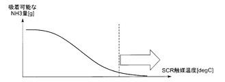
- the adsorption amount of NH 3 decreases by increasing the SCR catalyst temperature. That is, when the SCR catalyst temperature is raised, the amount of adsorption of NH 3 is lowered, and NH 3 is almost discharged as it is. This is the initialization of the SCR catalyst. Since it is difficult to actually measure the NH 3 adsorption amount, it is estimated from the urea (NH 3 ) injection amount and the NH 3 injection amount for purifying the NOx amount upstream of the SCR as in the following equation.
- NH 3 adsorption amount estimated value (g) ⁇ (urea injection amount ⁇ purification NH 3 injection amount) (1) Then, for example, a NOx purification rate is derived from a map showing the relationship between the estimated NH 3 adsorption amount and the SCR catalyst temperature, and the NOx purification rate and the NOx amount upstream of the SCR catalyst are calculated to calculate the NOx downstream of the SCR catalyst. Estimate the amount. If the estimated NOx amount downstream of the SCR catalyst then increases compared to the actual measured value of the NOx amount downstream of the SCR catalyst, the subsequent processing is continued with such erroneous data. As a result, the error is accumulated, and it is determined that highly accurate urea injection amount control and suitable NOx purification cannot be achieved, and the SCR catalyst temperature is raised to initialize the SCR catalyst.
- the exhaust purification controller unit determines the necessity of initialization of the SCR catalyst based on the error between the estimated NOx amount and the measured NOx amount downstream of the SCR catalyst. A necessity determining unit.
- the SCR catalyst initialization necessity determination unit is configured to determine the necessity of initialization of the SCR catalyst based on an elapse of a predetermined time after completion of the temperature increase of the SCR catalyst.
- the SCR catalyst temperature increase command for increasing the temperature of the SCR catalyst can be issued only when it is necessary to initialize the SCR catalyst.
- an exhaust gas purification method for an internal combustion engine in which NOx in the exhaust gas of the internal combustion engine is purified by an SCR catalyst disposed in an exhaust passage of the internal combustion engine, from the upstream side of the SCR catalyst.
- the NH 3 adsorption amount estimation value to be adsorbed from the NH 3 amount for purifying injection amount and the SCR catalyst upstream of the NOx of the NH 3 generated from the urea water to the SCR catalyst
- the estimated NOx amount downstream of the SCR catalyst is derived from the NH 3 adsorption amount estimated value and the SCR catalyst temperature, and based on the error between the NOx amount estimated value and the measured NOx amount downstream of the SCR catalyst.
- the NOx amount estimated value downstream of the SCR catalyst can be derived from the NH 3 adsorption amount estimated value and the SCR catalyst temperature.
- An error between the estimated NOx amount downstream of the SCR catalyst and the measured NOx amount downstream of the SCR catalyst is obtained, and the necessity of initialization of the SCR catalyst can be determined from the error.
- the adsorption amount of NH 3 decreases by increasing the SCR catalyst temperature.
- NH 3 injected from the upstream side of the SCR catalyst is not adsorbed by the SCR catalyst, and the SCR catalyst is in a state where NOx purification cannot be achieved at all, and initialization of the SCR catalyst is achieved.
- an SCR catalyst temperature increase possibility determination procedure for determining that the SCR catalyst can be increased in temperature is executed.
- the necessity determination procedure for SCR catalyst initialization when the error lower limit value> the integrated value of NOx error, or when the error upper limit value ⁇ the integrated value of NOx error, the necessity of the SCR catalyst is required. It is characterized by determining sex.
- the present invention according to claim 8 is characterized in that, in the SCR catalyst initialization necessity determination procedure, the necessity of the SCR catalyst is determined when a specified time has elapsed after the completion of the temperature increase of the SCR catalyst.
- the SCR catalyst temperature increasing procedure is performed by controlling the inlet temperature of the PM removal filter for collecting PM (particulate matter) in the exhaust upstream of the SCR catalyst. It is performed by control at the time of forced regeneration of the filter.
- the invention according to claim 10 is characterized in that the inlet temperature control of the PM removal filter is performed based on a target inlet temperature different from that during forced regeneration of the PM removal filter.
- the present invention according to claim 11 is characterized in that the inlet target temperature is raised at a predetermined rate of increase from the start of raising the temperature.
- the present invention according to claim 12 is characterized in that the increase of the inlet target temperature is set in a plurality of stages from the start of the temperature increase.
- the present invention according to claim 13 is characterized in that the inlet target temperature is corrected by the SCR catalyst temperature or the SCR catalyst upstream temperature.
- the present invention according to claim 14 is characterized in that when controlling the inlet temperature of the PM removal filter, the control is performed based on the outlet temperature of the PM removal filter.
- the present invention according to claim 15 is characterized in that the inlet temperature control of the PM removal filter is performed based on the temperature upstream of the SCR catalyst.
- the present invention according to claim 16 is characterized in that, when controlling the inlet temperature of the PM removal filter, the temperature is controlled based on the temperature of the SCR catalyst.
- the NH 3 adsorption amount estimated value is calculated, the NOx amount estimated value downstream of the SCR catalyst is derived, and the error between the NOx amount estimated value downstream of the SCR catalyst and the NOx amount measured value downstream of the SCR catalyst is calculated. Since the necessity of SCR catalyst initialization is determined and the SCR catalyst initialization can be achieved by raising the SCR catalyst temperature, the complicated initialization procedure and the complicated calculation as before are performed. It becomes unnecessary.
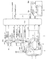
- FIG. 1 is a schematic system diagram according to a first embodiment of an internal combustion engine for carrying out an exhaust gas purification method for an internal combustion engine according to the present invention.
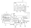
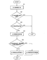
- FIG. 2 is a schematic configuration diagram of main parts of an exhaust emission control device in the internal combustion engine shown in FIG. 1. It is a flowchart which shows the SCR catalyst initialization process concerning 1st Embodiment. It is a graph showing the amount of NH 3 as possible adsorption to the SCR catalyst temperature. NH 3 and compared to the time course of the adsorption amount estimation value and the actual NH 3 adsorption is a graph showing the evolution of the SCR catalyst temperature in each case.
- FIG. 10 is a block diagram showing a flow of a specific correction procedure when correcting the DPF inlet target temperature shown in FIG. 9.
- FIG. 1 shows an example of an intake / exhaust system and an electrical system of an internal combustion engine 1 provided with the exhaust emission control device according to the first embodiment.
- the internal combustion engine 1 includes an intake / exhaust system in which an intake pipe 3, an exhaust pipe 4, and an EGR pipe 5 are connected to an engine body 2.
- the compressor and turbine of the supercharger 6 are interposed in the flow path of the exhaust pipe 4 upstream of the intake pipe 3 and in the vicinity of the engine outlet, and the intercooler 7 is provided in the intake pipe 3.
- the intake pipe 3 is provided with an intake throttle valve 8, and the EGR pipe 5 is provided with an EGR valve 9.
- the exhaust pipe 4 is connected to an exhaust purification device 10 as an exhaust gas aftertreatment device.
- An ECU 11 electronic control unit, that is, an engine control unit
- the vehicle-mounted battery 13 is electrically connected to the ECU 11 through the key switch Sw.
- a starter motor Mst is electrically connected to the in-vehicle battery 13 through a key switch Sw.
- an injector for example, an injector, a common rail pressure sensor, a fuel temperature sensor, a crank sensor, a cam sensor, a water temperature sensor, and a hydraulic switch (all not shown) are arranged in the engine body 2 to exchange signals with the ECU 11.
- an air flow meter m ef On the upstream side of the intake pipe 3, an air flow meter m ef , an intake temperature sensor S int , on the downstream side of the intake pipe 3, that is, on the inlet side of the engine body 2, an intake throttle valve 8, an intake absolute pressure sensor S ap , an intake air temperature A sensor S int is arranged.
- An EGR valve 9 is disposed in the EGR pipe 5.
- the exhaust purification device 10 has an oxidation catalyst 20 (here, DOC: Diesel Oxidation Catalyst) disposed on the upstream side of the exhaust pipe 4 constituting the exhaust passage connected to the engine body 2.
- the exhaust purification device 10 is disposed on the downstream side of the oxidation catalyst 20 and is disposed on the downstream side of the SCR catalyst 21 for purifying NOx in the exhaust of the engine body 2.
- an oxidation catalyst 22 for removing excess ammonia discharged from the reactor.
- a DPF 23 Diesel Particulate Filter
- PM removal filter that collects PM (particulate matter) in the exhaust gas.
- FIG. 1 it is shown that the DPF 23 is accommodated integrally with the DOC 20.
- a urea injection unit 24 that injects urea water is provided on the downstream side of the DPF 23 and the upstream side of the SCR catalyst 21.
- the urea injection unit 24 includes an electromagnetic injection valve 24v in which an injection nozzle enters the exhaust pipe 4, and a tank unit 24t that stores urea water.
- ammonia NH 3 serving as a direct reducing agent is generated by a chemical reaction from evaporation due to exhaust heat to hydrolysis. Is done. NH 3 and NOx in the exhaust gas react with each other while passing through the SCR catalyst 21, and NOx purification is performed by a reaction that changes into nitrogen N 2 and water H 2 O. Further, in this case, the detection signals from the NOx sensors S n1 and S n2 respectively arranged upstream and downstream of the SCR catalyst 21 are taken into the ECU 11 through CAN, and the operating temperature, engine speed, etc.
- the injection amount of the urea aqueous solution is controlled in accordance with important engine parameters.
- the engine body 2 and the intake pipe 3, the exhaust pipe 4, the EGR pipe 5, and sensor outputs from various sensors disposed in the exhaust purification device 10, the accelerator input Based on the signal, predetermined signal processing, calculation processing, and further a procedure of NOx purification processing of the exhaust purification device 10 are executed.
- the ECU 11 is provided with an exhaust purification controller unit 11C for executing the procedure of the NOx purification process.
- the exhaust purification controller unit 11C includes an NH3 adsorption amount estimated value calculation unit A, an NOx amount estimated value derivation unit B, an SCR catalyst temperature increase command unit C, an SCR catalyst initialization necessity determination unit D, and an SCR catalyst temperature increase. It has a possibility determination unit E and a temperature increase end determination unit F of the SCR catalyst.
- NH3 adsorption amount estimation value calculating portion A from the upstream side of the SCR catalyst, by injecting urea water into the exhaust passage 4, the injection quantity and NH 3 for purifying SCR catalyst upstream of the NOx of the NH 3 generated from the urea water
- An estimated NH 3 adsorption amount adsorbed on the SCR catalyst is calculated from the ejection amount.
- the NOx amount estimated value derivation section B derives the adsorbed NH 3 amount estimating value and the NOx amount estimation value of the SCR catalyst downstream from the SCR catalyst temperature from the NH3 adsorption amount estimation value calculation unit.
- the SCR catalyst temperature increase command unit C increases the SCR catalyst temperature based on the error between the NOx amount estimated value from the NOx amount estimated value deriving unit and the NOx amount measured value downstream of the SCR catalyst to estimate the NH3 adsorption amount.
- the SCR catalyst is initialized by initializing the value.
- the SCR catalyst initialization necessity determination unit D measures the error between the estimated NOx amount and the measured NOx amount downstream of the SCR catalyst, or when the predetermined time has elapsed after the temperature increase of the SCR catalyst, or downstream of the SCR catalyst. The necessity of initialization of the SCR catalyst is determined based on the value.
- the SCR catalyst temperature rise determination unit E determines that the temperature of the SCR catalyst can be raised when the operation is in an operation region where the temperature can be raised and the forced regeneration of the filter for removing the particulate matter in the exhaust is unnecessary.
- the exhaust purification controller unit has an SCR catalyst temperature rise end determination unit F.
- the first embodiment of the exhaust gas purification apparatus for carrying out the exhaust gas purification method for an internal combustion engine according to the present invention is as described above.
- a series of operations of the internal combustion engine 1 and the procedure of the NOx purification process of the exhaust gas purification apparatus 10 are performed. Will be described. Since a series of operations of the internal combustion engine 1 is not the gist of the present invention, it will be schematically described.
- the key switch Sw is turned on, the ECU 11 is energized from the in-vehicle battery 13 and the starter motor Mst is driven to rotate the crankshaft of the engine body 2.
- fuel is injected into the cylinder through the injector in response to a command from the ECU 11, and the engine is started.
- the combustion air sucked through the intake pipe 3 becomes high-pressure and high-temperature air by the compressor of the supercharger 6, is cooled by the intercooler 7, and is sent into the cylinder in the engine body 2, while the high-pressure air is Fuel is injected into the cylinder through the common rail Cr and the fuel injection valve Vf, and combustion is started.
- the combustion gas is exhausted to the exhaust purification device 10 through the exhaust pipe 4 while rotating the turbine of the supercharger 6. A part of the exhaust gas is recirculated into the cylinder of the engine body 2 through the EGR pipe 5 and is again used for combustion.
- the exhaust gas sent to the exhaust gas purification device 10 through the exhaust pipe 4 sequentially passes through the DOC 20 and DPF 23 that are oxidation catalysts, respectively, burns unburned components in the PM in the exhaust gas, removes the PM, and removes the SCR catalyst 21.
- NOx in the exhaust gas is purified by passing through the exhaust gas, and excess ammonia discharged from the SCR catalyst 21 is removed and discharged by the oxidation catalyst 22 on the downstream side of the SCR catalyst 21.
- urea water is injected into the exhaust pipe 4 through the electromagnetic injection valve 24v in the urea injection unit 24, and a direct reducing agent and a chemical reaction from evaporation due to exhaust heat to hydrolysis. Ammonia NH 3 is produced.
- NH 3 and NOx in the exhaust gas react with each other while passing through the SCR catalyst 21, and NOx can be purified by a reaction that changes into nitrogen N 2 and water H 2 O.
- the NH 3 adsorption amount estimated value calculation unit A calculates the NH 3 adsorption amount (step S1). As described above, the amount of NH 3 that can be adsorbed on the SCR catalyst varies depending on the SCR catalyst temperature. For example, FIG. 4 illustrates the relationship between the SCR catalyst temperature and the amount of NH 3 that can be adsorbed.
- the urea injection amount is the amount of NH 3 injected from the urea injection unit 24 on the upstream side of the SCR catalyst 21, and the purification NH 3 injection amount is the amount of NH 3 necessary for purification. It is obtained by a predetermined calculation.
- the NOx amount estimated value deriving unit B derives the NOx amount estimated value downstream of the SCR catalyst from the NH 3 adsorption amount estimated value and the SCR catalyst temperature from the NH 3 adsorption amount estimated value calculating unit A.
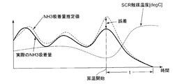
- the NOx amount estimation value are those corresponding to the adsorbed NH 3 amount estimating values can be displayed as a curve of the adsorbed NH 3 amount estimating value as shown by the broken line in FIG. 5, for example.
- the measured NOx amount downstream of the SCR catalyst is assumed as indicated by the solid line as the actual NH 3 adsorption amount.
- the SCR catalyst temperature is shown.
- the difference between the estimated NH 3 adsorption amount (the estimated NOx amount downstream of the SCR catalyst) and the actual NH 3 adsorption amount (the measured NOx amount downstream of the SCR catalyst) is increasing. It is shown.
- the exhaust gas purification controller unit 11C of the ECU 11 executes a procedure for determining the necessity of SCR catalyst initialization in step S2.
- the SCR catalyst initialization necessity determination unit D (1)
- NOx error at the SCR catalyst outlet is large
- NH3 adsorption amount estimated value NOx amount estimation downstream of SCR catalyst
- the actual NH3 adsorption amount measured value of NOx amount downstream of the SCR catalyst
- NOx error SCR catalyst downstream NOx amount (purification NH 3 injection amount (sensor measured value)) ⁇ SCR catalyst downstream NOx amount estimation Value (NH 3 adsorption amount estimate)
- a prescribed time for example, 30 Hr to 50 Hr
- NH 3 slip has occurred from the value of the NOx sensor S n2 on the downstream side of the SCR catalyst.
- the exhaust purification controller unit 11C of the ECU 11 determines whether or not the SCR catalyst temperature can be increased in step S3. However, when the following conditions (1) and (2) are satisfied, it is determined that the SCR catalyst temperature can be increased. That is, in the SCR catalyst temperature rise determination unit E, (1) When operating in an operation region in which the temperature can be increased according to the temperature increase possible determination map In this case, it is necessary to create a map in advance.
- (2) State in which forced regeneration is not required in DPF forced regeneration DPF forced regeneration is a state in which it is necessary to perform forced regeneration of DPF by an operation of performing combustion regeneration, for example, by clogging with PM by Late Post injection or the like. If there is, priority is given to DPF forced regeneration. This is because if the DPF forced regeneration is performed, the temperature of the SCR catalyst is also raised.
- step S4 the exhaust purification controller unit 11C of the ECU 11 outputs a temperature increase command for the SCR catalyst. That is, in the SCR catalyst temperature increase command unit C, (1)
- the DPF inlet temperature control when the SCR catalyst temperature rises is the same control method as the control during DPF forced regeneration. Thereby, control can be simplified.
- the throttle valve 8 is throttled and the temperature is increased by Early Post injection.
- Post injection refers to injecting excess fuel into the cylinder after main injection.
- the DPF inlet temperature is controlled by Late Post injection. This is because it is difficult to control the SCR catalyst upstream temperature.
- a DPF temperature at which the SCR catalyst temperature is 450 ° C. or higher is obtained in advance, and that temperature is set as a target temperature.
- the SCR catalyst upstream temperature is raised by the throttle valve 8 and the temperature is increased by Early Post injection.
- the exhaust purification controller unit 11C of the ECU 11 performs the SCR catalyst temperature rise end determination in step S5.
- the temperature rise end determination unit F When the SCR catalyst temperature> temperature threshold (400 to 450 ° C.) has elapsed, the temperature raising process is completed. In that case, the time t at which NH 3 adsorbed on the SCR catalyst becomes almost zero from the start of temperature rise is determined in advance.
- the estimated NH 3 adsorption amount and the actual NH 3 adsorption amount become 0, and the estimated NH 3 adsorption amount is initialized, that is, the initialization of the SCR catalyst. Is achieved.
- the initialization of the SCR catalyst can be achieved by raising the SCR catalyst temperature, so that the complicated initialization procedure as described above and the complicated calculation are performed. It becomes unnecessary.
- the present invention can be implemented as in the following second embodiment.
- the DPF inlet temperature control is executed while changing the parameters as in DPF forced regeneration.
- the DPF inlet target temperature achieved by the DPF inlet temperature control is about 500 ° C. (In the case of forced regeneration of DPF, about 600 ° C)
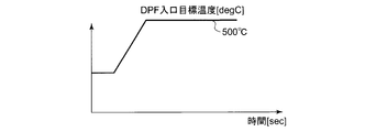
- the temperature of the DPF inlet is raised by the DPF inlet temperature control, the temperature is raised to the target temperature at a constant rate (deg./sec) from the start of raising the temperature over an appropriate time.
- FIGS. 6, 7, and 8 show a case where the temperature is raised so as to reach the target temperature (500 ° C.) in one step from the initial temperature of the DPF inlet.
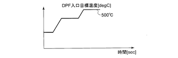
- FIG. 7 shows a case where the temperature is raised so as to reach the target temperature (500 ° C.) in two stages from the initial temperature of the DPF inlet.
- FIG. 8 shows a case where the temperature is raised so as to reach the target temperature (500 ° C.) in two stages from the initial temperature of the DPF inlet in multiple stages.
- the target temperature of the DPF inlet is increased at a constant rate from the start of raising the temperature, so that the NH 3 adsorption amount during the increase is secured, and NH 3 slip occurs due to a sharp decrease in the NH 3 adsorption amount. Can be suppressed.
- this invention can be implemented like the following 3rd Embodiment.
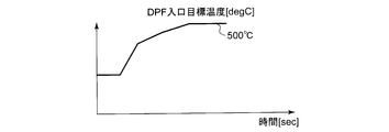
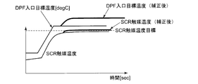
- the SCR catalyst cannot be heated to a required temperature due to an environmental change such as an increase in heat dissipation of the exhaust pipe at a low outside air temperature. If you want to deal with it. Therefore, the SCR catalyst can be raised to a necessary temperature by correcting the DPF inlet temperature with the SCR catalyst temperature or the SCR catalyst upstream temperature (see FIG. 9).
- FIG. 9 shows the temporal change of the target DPF inlet temperature with respect to the DPF inlet temperature, and shows the temporal change of the temperature of the SCR catalyst that changes accordingly.
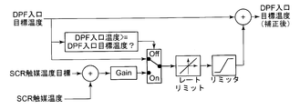
- FIG. 10 shows a specific procedure of the correction procedure for reaching the corrected DPF inlet target value indicated by the thick solid line shown in FIG. That is, FIG. 10 shows a procedure for correcting the DPF inlet target temperature using the SCR catalyst temperature or the SCR catalyst target temperature. Such a correction procedure is executed when the DPF inlet temperature is compared with the DPF inlet target temperature and the DPF inlet temperature is lower than the DPF inlet target temperature.
- the corrected DPF inlet target temperature is reached from the DPF inlet temperature with a predetermined rate limit (temperature increase rate) and a predetermined limiter.
- a gain is obtained in consideration of a deviation between an SCR catalyst temperature target (for example, 450 ° C.) and an SCR catalyst temperature (an SCR catalyst upstream temperature, for example, 400 ° C.) so as to eliminate the deviation, and a predetermined rate.
- SCR catalyst temperature target for example, 450 ° C.
- SCR catalyst temperature upstream temperature for example, 400 ° C.
- the DPF inlet target temperature is corrected by performing the correction procedure based on the SCR catalyst temperature target and the SCR catalyst temperature (SCR catalyst upstream temperature).
- the temperature of the catalyst can be increased.
- the temperature control target at the time of raising the temperature of the SCR catalyst is (1) the DPF outlet temperature, (2) the SCR upstream temperature, or (3 ) SCR catalyst temperature.
- the control target is an SCR catalyst, the temperature of the SCR catalyst can be raised to a required temperature or higher.
- the initialization of the SCR catalyst can be achieved by increasing the SCR catalyst temperature, it is not necessary to perform complicated initialization procedures and complicated calculations as in the past. .
- the manufacturing cost can be suppressed in an apparatus, and the applicability to various engines is high. .
Landscapes
- Engineering & Computer Science (AREA)
- Chemical & Material Sciences (AREA)
- Combustion & Propulsion (AREA)
- Chemical Kinetics & Catalysis (AREA)
- General Engineering & Computer Science (AREA)
- Mechanical Engineering (AREA)
- Health & Medical Sciences (AREA)
- General Chemical & Material Sciences (AREA)
- Oil, Petroleum & Natural Gas (AREA)
- Analytical Chemistry (AREA)
- Environmental & Geological Engineering (AREA)
- Biomedical Technology (AREA)
- Toxicology (AREA)
- Exhaust Gas After Treatment (AREA)
- Processes For Solid Components From Exhaust (AREA)
Priority Applications (4)
| Application Number | Priority Date | Filing Date | Title |
|---|---|---|---|
| US14/421,797 US10029210B2 (en) | 2012-10-30 | 2013-10-25 | Exhaust gas purification apparatus and method for internal combustion engine |
| IN1131DEN2015 IN2015DN01131A (OSRAM) | 2012-10-30 | 2013-10-25 | |
| EP13850570.6A EP2915969B1 (en) | 2012-10-30 | 2013-10-25 | Exhaust purification device and exhaust purification method for internal combustion engine |
| CN201380043174.XA CN104583550B (zh) | 2012-10-30 | 2013-10-25 | 内燃机的排气净化装置及其排气净化方法 |
Applications Claiming Priority (2)
| Application Number | Priority Date | Filing Date | Title |
|---|---|---|---|
| JP2012238691A JP6087580B2 (ja) | 2012-10-30 | 2012-10-30 | 内燃機関の排気浄化装置およびその排気浄化方法 |
| JP2012-238691 | 2012-10-30 |
Publications (1)
| Publication Number | Publication Date |
|---|---|
| WO2014069342A1 true WO2014069342A1 (ja) | 2014-05-08 |
Family
ID=50627251
Family Applications (1)
| Application Number | Title | Priority Date | Filing Date |
|---|---|---|---|
| PCT/JP2013/078901 Ceased WO2014069342A1 (ja) | 2012-10-30 | 2013-10-25 | 内燃機関の排気浄化装置およびその排気浄化方法 |
Country Status (6)
| Country | Link |
|---|---|
| US (1) | US10029210B2 (OSRAM) |
| EP (1) | EP2915969B1 (OSRAM) |
| JP (1) | JP6087580B2 (OSRAM) |
| CN (1) | CN104583550B (OSRAM) |
| IN (1) | IN2015DN01131A (OSRAM) |
| WO (1) | WO2014069342A1 (OSRAM) |
Cited By (3)
| Publication number | Priority date | Publication date | Assignee | Title |
|---|---|---|---|---|
| CN106014556A (zh) * | 2015-03-26 | 2016-10-12 | 丰田自动车株式会社 | 内燃机的排气净化装置 |
| US10029210B2 (en) | 2012-10-30 | 2018-07-24 | Mitsubishi Heavy Industries Engine & Turbocharger, Ltd. | Exhaust gas purification apparatus and method for internal combustion engine |
| CN114046198A (zh) * | 2022-01-11 | 2022-02-15 | 潍柴动力股份有限公司 | 一种双dpf再生控制方法、装置和发动机 |
Families Citing this family (9)
| Publication number | Priority date | Publication date | Assignee | Title |
|---|---|---|---|---|
| JP6269614B2 (ja) * | 2015-08-06 | 2018-01-31 | トヨタ自動車株式会社 | 内燃機関の排気浄化装置 |
| JP6911638B2 (ja) * | 2017-08-28 | 2021-07-28 | いすゞ自動車株式会社 | 内燃機関の排気浄化装置 |
| JP6911639B2 (ja) * | 2017-08-28 | 2021-07-28 | いすゞ自動車株式会社 | 内燃機関の排気浄化装置 |
| JP7151119B2 (ja) * | 2018-03-26 | 2022-10-12 | マツダ株式会社 | エンジンの触媒異常判定方法、及び、エンジンの触媒異常判定装置 |
| JP7151120B2 (ja) * | 2018-03-26 | 2022-10-12 | マツダ株式会社 | エンジンの触媒異常判定方法、及び、エンジンの触媒異常判定装置 |
| CN109578123B (zh) * | 2018-11-27 | 2020-06-26 | 潍柴动力股份有限公司 | 一种柴油机氧化催化器失效判定方法及装置 |
| CN111350574B (zh) * | 2018-12-23 | 2024-12-27 | 营口福泰科技有限责任公司 | 一种汽车国6排放后处理系统 |
| JP7234950B2 (ja) * | 2020-01-14 | 2023-03-08 | 株式会社デンソー | 内燃機関の排気浄化制御装置 |
| EP4361412B1 (en) * | 2022-10-27 | 2025-09-03 | Volvo Truck Corporation | A method of operating a reducing agent injector |
Citations (6)
| Publication number | Priority date | Publication date | Assignee | Title |
|---|---|---|---|---|
| JP2001027113A (ja) * | 1999-07-16 | 2001-01-30 | Toyota Motor Corp | 内燃機関の排気浄化装置 |
| JP2003286828A (ja) * | 2002-03-27 | 2003-10-10 | Mitsubishi Fuso Truck & Bus Corp | 内燃機関のNOx浄化装置 |
| JP2009281350A (ja) | 2008-05-26 | 2009-12-03 | Nippon Soken Inc | 内燃機関の排気浄化装置 |
| JP2009293444A (ja) * | 2008-06-03 | 2009-12-17 | Nippon Soken Inc | 内燃機関の排気浄化装置 |
| JP2010248963A (ja) * | 2009-04-14 | 2010-11-04 | Nippon Soken Inc | 内燃機関の排気浄化装置 |
| JP2010261423A (ja) * | 2009-05-11 | 2010-11-18 | Toyota Motor Corp | 内燃機関の排気浄化装置 |
Family Cites Families (13)
| Publication number | Priority date | Publication date | Assignee | Title |
|---|---|---|---|---|
| US6314722B1 (en) * | 1999-10-06 | 2001-11-13 | Matros Technologies, Inc. | Method and apparatus for emission control |
| US6993900B2 (en) * | 2002-10-21 | 2006-02-07 | Ford Global Technologies, Llc | Exhaust gas aftertreatment systems |
| US7858060B2 (en) * | 2008-07-30 | 2010-12-28 | Gm Global Technology Operations, Inc | Current storage estimation for selective catalytic reduction catalysts |
| US8596042B2 (en) * | 2008-08-28 | 2013-12-03 | Delphi International Operations Luxembourg S.A.R.L. | System and method for selective catalytic reduction control |
| JP4729631B2 (ja) * | 2009-03-11 | 2011-07-20 | トヨタ自動車株式会社 | 内燃機関の排気浄化装置 |
| JP2010265862A (ja) * | 2009-05-18 | 2010-11-25 | Toyota Industries Corp | 排気ガス浄化装置 |
| US8479496B2 (en) * | 2009-07-02 | 2013-07-09 | GM Global Technology Operations LLC | Selective catalytic reduction system using electrically heated catalyst |
| US8584444B2 (en) * | 2010-02-09 | 2013-11-19 | General Electric Company | Model-based controls for selective catalyst reduction system |
| US8733083B2 (en) * | 2010-04-26 | 2014-05-27 | Cummins Filtration Ip, Inc. | SCR catalyst ammonia surface coverage estimation and control |
| CN101832167B (zh) * | 2010-05-07 | 2012-07-11 | 东风汽车有限公司 | 一种scr催化器中的氨气吸附控制方法 |
| DE102010029740B4 (de) | 2010-06-07 | 2022-05-12 | Robert Bosch Gmbh | Verfahren zur Überwachung eines SCR-Katalysators |
| JP5002040B2 (ja) * | 2010-07-07 | 2012-08-15 | トヨタ自動車株式会社 | 内燃機関の排気浄化装置 |
| JP6087580B2 (ja) | 2012-10-30 | 2017-03-01 | 三菱重工業株式会社 | 内燃機関の排気浄化装置およびその排気浄化方法 |
-
2012
- 2012-10-30 JP JP2012238691A patent/JP6087580B2/ja active Active
-
2013
- 2013-10-25 US US14/421,797 patent/US10029210B2/en active Active
- 2013-10-25 WO PCT/JP2013/078901 patent/WO2014069342A1/ja not_active Ceased
- 2013-10-25 EP EP13850570.6A patent/EP2915969B1/en active Active
- 2013-10-25 IN IN1131DEN2015 patent/IN2015DN01131A/en unknown
- 2013-10-25 CN CN201380043174.XA patent/CN104583550B/zh active Active
Patent Citations (6)
| Publication number | Priority date | Publication date | Assignee | Title |
|---|---|---|---|---|
| JP2001027113A (ja) * | 1999-07-16 | 2001-01-30 | Toyota Motor Corp | 内燃機関の排気浄化装置 |
| JP2003286828A (ja) * | 2002-03-27 | 2003-10-10 | Mitsubishi Fuso Truck & Bus Corp | 内燃機関のNOx浄化装置 |
| JP2009281350A (ja) | 2008-05-26 | 2009-12-03 | Nippon Soken Inc | 内燃機関の排気浄化装置 |
| JP2009293444A (ja) * | 2008-06-03 | 2009-12-17 | Nippon Soken Inc | 内燃機関の排気浄化装置 |
| JP2010248963A (ja) * | 2009-04-14 | 2010-11-04 | Nippon Soken Inc | 内燃機関の排気浄化装置 |
| JP2010261423A (ja) * | 2009-05-11 | 2010-11-18 | Toyota Motor Corp | 内燃機関の排気浄化装置 |
Non-Patent Citations (1)
| Title |
|---|
| See also references of EP2915969A4 |
Cited By (4)
| Publication number | Priority date | Publication date | Assignee | Title |
|---|---|---|---|---|
| US10029210B2 (en) | 2012-10-30 | 2018-07-24 | Mitsubishi Heavy Industries Engine & Turbocharger, Ltd. | Exhaust gas purification apparatus and method for internal combustion engine |
| CN106014556A (zh) * | 2015-03-26 | 2016-10-12 | 丰田自动车株式会社 | 内燃机的排气净化装置 |
| CN114046198A (zh) * | 2022-01-11 | 2022-02-15 | 潍柴动力股份有限公司 | 一种双dpf再生控制方法、装置和发动机 |
| CN114046198B (zh) * | 2022-01-11 | 2022-03-15 | 潍柴动力股份有限公司 | 一种双dpf再生控制方法、装置和发动机 |
Also Published As
| Publication number | Publication date |
|---|---|
| CN104583550B (zh) | 2017-08-15 |
| US20150231569A1 (en) | 2015-08-20 |
| IN2015DN01131A (OSRAM) | 2015-06-26 |
| US10029210B2 (en) | 2018-07-24 |
| EP2915969A4 (en) | 2016-06-01 |
| EP2915969A1 (en) | 2015-09-09 |
| JP6087580B2 (ja) | 2017-03-01 |
| CN104583550A (zh) | 2015-04-29 |
| JP2014088800A (ja) | 2014-05-15 |
| EP2915969B1 (en) | 2018-02-28 |
Similar Documents
| Publication | Publication Date | Title |
|---|---|---|
| JP6087580B2 (ja) | 内燃機関の排気浄化装置およびその排気浄化方法 | |
| US9943806B2 (en) | Exhaust gas purification system | |
| CN102037230B (zh) | NOx传感器的异常诊断装置及异常诊断方法 | |
| JP2006125247A (ja) | エンジンの排気ガス浄化方法及び排気ガス浄化装置 | |
| US20160376972A1 (en) | Exhaust control system for internal combustion engine | |
| US8540953B2 (en) | Exhaust gas control apparatus and reductant dispensing method for internal combustion engine | |
| WO2015170643A1 (ja) | 排気浄化システム | |
| EP3073086B1 (en) | Exhaust gas control apparatus for internal combustion engine | |
| JP2010031731A (ja) | 内燃機関の排気浄化装置 | |
| US9512785B2 (en) | Exhaust gas purification system for internal combustion engine | |
| CN109154223B (zh) | 内燃机的排气气体净化系统及内燃机的排气气体净化方法 | |
| EP3135875B1 (en) | Exhaust purifying system | |
| EP3056701B1 (en) | Exhaust purification system | |
| JP4419150B2 (ja) | NOx触媒の異常診断装置及び異常診断方法 | |
| JP6071636B2 (ja) | 内燃機関の制御装置およびその制御方法 | |
| JP2019073980A (ja) | 内燃機関の排気浄化装置 | |
| WO2015015296A1 (en) | Control device for internal combustion engine and method of controlling internal combustion engine | |
| JP5543725B2 (ja) | 排気浄化装置 | |
| JP2018031285A (ja) | 昇温システム | |
| JP2019035379A (ja) | 内燃機関の排気浄化装置 |
Legal Events
| Date | Code | Title | Description |
|---|---|---|---|
| 121 | Ep: the epo has been informed by wipo that ep was designated in this application |
Ref document number: 13850570 Country of ref document: EP Kind code of ref document: A1 |
|
| WWE | Wipo information: entry into national phase |
Ref document number: 14421797 Country of ref document: US Ref document number: 2013850570 Country of ref document: EP |
|
| NENP | Non-entry into the national phase |
Ref country code: DE |