WO2014069129A1 - 放射線信号処理装置、放射線画像撮影システム、及び放射線信号処理方法 - Google Patents
放射線信号処理装置、放射線画像撮影システム、及び放射線信号処理方法 Download PDFInfo
- Publication number
- WO2014069129A1 WO2014069129A1 PCT/JP2013/076131 JP2013076131W WO2014069129A1 WO 2014069129 A1 WO2014069129 A1 WO 2014069129A1 JP 2013076131 W JP2013076131 W JP 2013076131W WO 2014069129 A1 WO2014069129 A1 WO 2014069129A1
- Authority
- WO
- WIPO (PCT)
- Prior art keywords
- radiation
- irradiation
- signal
- signal processing
- dose
- Prior art date
- Legal status (The legal status is an assumption and is not a legal conclusion. Google has not performed a legal analysis and makes no representation as to the accuracy of the status listed.)
- Ceased
Links
Images


Classifications
-
- H—ELECTRICITY
- H05—ELECTRIC TECHNIQUES NOT OTHERWISE PROVIDED FOR
- H05G—X-RAY TECHNIQUE
- H05G1/00—X-ray apparatus involving X-ray tubes; Circuits therefor
- H05G1/08—Electrical details
- H05G1/26—Measuring, controlling or protecting
- H05G1/30—Controlling
- H05G1/38—Exposure time
- H05G1/42—Exposure time using arrangements for switching when a predetermined dose of radiation has been applied, e.g. in which the switching instant is determined by measuring the electrical energy supplied to the tube
- H05G1/44—Exposure time using arrangements for switching when a predetermined dose of radiation has been applied, e.g. in which the switching instant is determined by measuring the electrical energy supplied to the tube in which the switching instant is determined by measuring the amount of radiation directly
-
- A—HUMAN NECESSITIES
- A61—MEDICAL OR VETERINARY SCIENCE; HYGIENE
- A61B—DIAGNOSIS; SURGERY; IDENTIFICATION
- A61B6/00—Apparatus or devices for radiation diagnosis; Apparatus or devices for radiation diagnosis combined with radiation therapy equipment
- A61B6/42—Arrangements for detecting radiation specially adapted for radiation diagnosis
- A61B6/4208—Arrangements for detecting radiation specially adapted for radiation diagnosis characterised by using a particular type of detector
- A61B6/4233—Arrangements for detecting radiation specially adapted for radiation diagnosis characterised by using a particular type of detector using matrix detectors
-
- A—HUMAN NECESSITIES
- A61—MEDICAL OR VETERINARY SCIENCE; HYGIENE
- A61B—DIAGNOSIS; SURGERY; IDENTIFICATION
- A61B6/00—Apparatus or devices for radiation diagnosis; Apparatus or devices for radiation diagnosis combined with radiation therapy equipment
- A61B6/54—Control of apparatus or devices for radiation diagnosis
- A61B6/542—Control of apparatus or devices for radiation diagnosis involving control of exposure
Definitions
- the present invention relates to a radiation signal processing apparatus, a radiation image capturing system, and a radiation signal processing method.
- radiation detectors such as FPD (Flat Panel Detector) that can arrange radiation sensitive layers on TFT (Thin Film Transistor) active matrix substrates and convert radiation dose into digital data (electrical signals) (referred to as “electronic cassettes”)
- FPD Fluor Deposition Detector
- TFT Thin Film Transistor
- electrospray cassettes a radiation image capturing apparatus that captures a radiation image represented by the amount of irradiated radiation using this radiation detector has been put into practical use.
- Some of such radiographic imaging apparatuses monitor radiation dose in order to control radiation start and stop.
- wireless communication In order to convey the detection result without error, it is exchanged with a digital signal.
- the radiation generator side makes a decision to stop the irradiation based on the cumulative amount of irradiated radiation
- the radiation imaging apparatus side sends information on the detected irradiation dose to the radiation generator side as needed during the radiation irradiation period. become.
- wirelessly exchanging digital signals it is naturally impossible to receive temporarily if the wireless strength is unstable, so the radiation generator side receives discrete information in terms of time.
- the cumulative amount of dose increases during the blank period between receiving dose information at a certain timing and receiving dose information at the next timing. I do not know. Therefore, when the dose information is received at the next timing, the necessary accumulated value may already be exceeded.
- the present invention has been made in consideration of the above facts, and an object thereof is to enable radiation irradiation stop control with high accuracy in a system that performs radiation irradiation stop control wirelessly.
- the radiation signal processing apparatus of the present invention captures an image corresponding to the irradiated radiation, detects the radiation dose, and outputs a signal representing the detection result from the radiation imaging apparatus.
- a receiving unit that receives a signal representing a detection result as a digital signal, and a digital signal that represents the detection result received by the receiving unit when the radiation imaging apparatus is irradiated with radiation and the radiation reaches a predetermined dose.
- Conversion means for converting the signal into an analog signal that can be recognized by the radiation irradiation apparatus that stops the radiation irradiation.
- the receiving means receives a signal representing the detection result of the radiation dose from the radiation imaging apparatus as a digital signal.
- the digital signal representing the detection result received by the receiving means is converted into an analog signal that can be recognized by the radiation irradiation apparatus. That is, by performing the conversion by the conversion means, the radiation irradiation stop control can be performed with high accuracy in a system that performs the radiation irradiation stop control wirelessly. In addition, radiation irradiation stop control can be performed by applying a radiation imaging apparatus capable of detecting the radiation irradiation amount to a system that performs radiation irradiation stop control using an ion chamber or the like.
- the receiving unit may receive the digital signal by wireless communication, and the converting unit may further output the analog signal to a radiation irradiation apparatus connected by wire.
- the receiving means may receive an irradiation stop notice signal indicating the irradiation time from the start of irradiation and the remaining irradiation time with respect to a predetermined appropriate irradiation time as the digital signal, or start of irradiation. May be received as the digital signal.
- the irradiation stop notice signal indicating the irradiation time from, the remaining irradiation time with respect to the predetermined appropriate irradiation time, and the unit of time may be received.
- the conversion means may obtain the voltage increase ⁇ per unit time from the digital signal, and convert the analog signal representing the voltage corresponding to the radiation dose by time integration.
- the conversion means can improve the accuracy of the signal by obtaining the voltage increase ⁇ per unit time based on the latest digital signal.
- the radiation imaging apparatus may transmit the irradiation stop notice signal that maximizes the voltage increase as the digital signal when the dose increases and stops immediately.
- a radiation imaging system having a function of detecting and outputting the dose of irradiated radiation and including a radiation image capturing device that captures a radiation image and the above-described radiation signal processing device may be configured. Good.
- the signal processing method of the radiographic imaging apparatus of the present invention captures an image corresponding to the irradiated radiation, and detects the radiation dose and outputs a signal representing the detection result from the radiographic imaging apparatus.
- a signal representing the result is received as a digital signal by the receiving means, and the received digital signal representing the detection result is irradiated to the radiation imaging apparatus and radiation irradiation is stopped when the radiation reaches a predetermined dose. It converts into an analog signal which can be recognized by the radiation irradiation apparatus.
- the signal representing the detection result of the radiation dose from the radiographic apparatus is received as a digital signal by the receiving means.
- the digital signal representing the received detection result is converted into an analog signal that can be recognized by the radiation irradiation apparatus. That is, by performing the conversion, the radiation irradiation stop control can be performed with high accuracy in a system that performs the radiation irradiation stop control wirelessly.
- radiation irradiation stop control can be performed by applying a radiation imaging apparatus capable of detecting the radiation irradiation amount to a system that performs radiation irradiation stop control using an ion chamber or the like.
- the digital signal may be received by wireless communication, and the analog signal may be further output to a radiation irradiation apparatus connected by wire.
- an irradiation stop notice signal indicating the irradiation time from the start of radiation irradiation and the remaining irradiation time with respect to a predetermined appropriate irradiation time may be received as the digital signal, or the irradiation time from the start of radiation irradiation And the irradiation stop notice signal showing the remaining irradiation time with respect to the predetermined appropriate irradiation time and the unit of time may be received as the digital signal.
- the voltage increase ⁇ per unit time may be obtained from the digital signal, and may be converted into an analog signal representing a voltage corresponding to the radiation dose by time integration. In this case, the accuracy of the signal can be improved by obtaining the voltage increase ⁇ per unit time based on the latest digital signal.
- the radiation imaging apparatus may transmit the irradiation stop notice signal that maximizes the voltage increase as the digital signal when the dose increases and stops immediately.
- the present invention may be a recording medium storing a program for causing a computer to execute the above-described radiation signal processing method.
- the present invention enables radiation irradiation stop control by applying a radiation imaging apparatus capable of detecting the amount of radiation irradiation to a related art system that performs radiation irradiation stop control using an ion chamber or the like. It has an excellent effect of being able to.
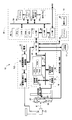
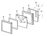
- FIG. 1 is a schematic configuration diagram of an outline of an overall configuration of an example of a radiographic image capturing system according to an embodiment. It is a figure which shows an example of the electronic cassette hold
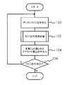
- FIG. It is a flowchart which shows an example of the flow of a process performed by I / F for AEC of the radiographic imaging system concerning this Embodiment.
- FIG. 1 shows a schematic configuration diagram of an overall configuration of an example of a radiographic imaging system according to the present exemplary embodiment.
- the radiographic image capturing system 10 of the present embodiment has a function in which the electronic cassette 20 itself detects a radiation irradiation start (imaging start) and a radiation irradiation stop (imaging end).
- the radiographic imaging system 10 of the present exemplary embodiment is based on an instruction (imaging menu) input from an external system (for example, RIS: Radiology Information System: radiation information system) via the console 16. It has a function of taking a radiographic image by an operation such as the above.
- an instruction for example, RIS: Radiology Information System: radiation information system
- the radiographic image capturing system 10 of the present embodiment has a function of causing a doctor, a radiographer, or the like to interpret a radiographic image by displaying the captured radiographic image on the display 50 of the console 16 or the radiographic image interpretation device 18. It is what you have.
- the radiographic imaging system 10 of the present exemplary embodiment includes a radiation generation device 12, a control device 14, a console 16, a storage unit 17, a radiographic image interpretation device 18, and an electronic cassette 20.
- the radiation generator 12 includes a power source 22, a radiation irradiation controller 23, and a high voltage generator 24.
- the radiation irradiation control unit 23 has a function of irradiating the imaging target region of the subject 30 with the radiation X from the radiation irradiation source 25 based on the control of the radiation control unit 62 of the control device 14.
- the radiation irradiation control unit 23 according to the present embodiment supplies the current supplied from the power supply 22 to the high voltage generator 24, supplies the high voltage generated by the high voltage generator 24 to the radiation irradiation source 25, and generates radiation.
- X is generated.
- the power source 22 may be either an AC power source or a DC power source.
- the high voltage generator 24 may be any of a single-phase transformer system, a three-phase transformer system, an inverter system, and a capacitor system.
- the installation type radiation generator 12 is shown in FIG. 1, it is not restricted to this, The radiation generator 12 may be a mobile type.
- the radiation X transmitted through the subject 30 is applied to the electronic cassette 20 held on the wall stand 28.
- the electronic cassette 20 is attached to a back bracket 32 provided on a wall stand 28 fixed to a wall.
- a cover 38 is provided on the radiation irradiation side of the electronic cassette 20.
- an ion chamber 34 having a plurality of lighting fields 34A to 34C for detecting the radiation dose and a bucky / grid 36 for removing scattered light can be arranged.
- the electronic cassette 20 outputs not only the image information indicating the radiation image but also a signal for stopping the radiation irradiation, and can control the radiation irradiation stop even without the ion chamber 34.
- the ion chamber 34 can be omitted. Or you may be comprised so that irradiation of a radiation can also be stopped using the ion chamber 34.
- the electronic cassette 20 has a function of generating a charge corresponding to the dose of the radiation X transmitted through the subject 30, and generating and outputting image information indicating a radiation image based on the generated charge amount.
- dose refers to radiation intensity, for example, radiation applied at a predetermined tube voltage and a predetermined tube current per unit time.
- FIG. 2 shows an example in which the electronic cassette 20 is held on the wall stand 28. However, a configuration may be adopted in which a photographing stand for a subject to lie down is provided and the electronic cassette 20 is held on the photographing stand.
- image information indicating the radiation image output by the electronic cassette 20 is input to the console 16 via the control device 14.
- the console 16 has a function of controlling the radiation generator 12 and the electronic cassette 20 by using an imaging menu and various information acquired from an external system (RIS) through wireless communication (LAN: Local Area Network). Have. Further, the console 16 has a function of transmitting / receiving various information including image information of radiographic images to / from the control device 14 and a function of transmitting / receiving various information to / from the electronic cassette 20.
- the console 16 is configured as a server computer, and includes a control unit 49, a display driver 48, a display 50, an operation input detection unit 52, an operation panel 54, an I / O unit 56, an I / F unit 57, and an I / F unit 57.
- / F unit 58 is provided.
- the control unit 49 has a function of controlling the operation of the entire console 16, and includes a CPU, a ROM, a RAM, and an HDD.
- the CPU has a function of controlling the operation of the entire console 16, and various programs including a control program used by the CPU are stored in advance in the ROM.
- the RAM has a function of temporarily storing various data
- the HDD hard disk drive
- the display driver 48 has a function of controlling display of various information on the display 50.
- the display 50 according to the present embodiment has a function of displaying an imaging menu, a captured radiographic image, and the like.
- the operation input detection unit 52 has a function of detecting an operation state with respect to the operation panel 54.
- the operation panel 54 is used by a doctor, a radiographer, or the like to input operation instructions related to radiographic image capturing.
- the operation panel 54 includes, for example, a touch panel, a touch pen, a plurality of keys, a mouse, and the like. When configured as a touch panel, it may be configured the same as the display 50.
- the I / O unit 56 and the I / F unit 58 transmit and receive various types of information to and from the control device 14 and the radiation generation device 12 through wireless communication and wired communication, and also perform an image with the electronic cassette 20. It has a function of transmitting and receiving various information such as information.
- the I / F unit 57 has a function of transmitting / receiving various types of information to / from the RIS.
- the control unit 49, the display driver 48, the operation input detection unit 52, the I / F unit 58, and the I / O unit 56 are connected so that information can be exchanged with each other via a bus 59 such as a system bus or a control bus.
- a bus 59 such as a system bus or a control bus.
- the control unit 49 controls the display of various information on the display 50 via the display driver 48 and controls the transmission / reception of various information with the radiation generator 12 and the electronic cassette 20 via the I / F unit 58. Can be performed respectively.
- the control device 14 has a function of controlling the radiation generation device 12 and the electronic cassette 20 based on an instruction from the console 16 and stores the radiation image received from the electronic cassette 20 in the storage unit 17. And a function of controlling display on the display 50 of the console 16 and the radiographic image interpretation device 18.
- control device 14 includes a system control unit 60, a radiation control unit 62, a panel control unit 64, an image processing control unit 66, and an I / F unit 68.
- the system control unit 60 has a function of controlling the entire control device 14 and a function of controlling the radiographic imaging system 10.
- the system control unit 60 includes a CPU, ROM, RAM, and HDD.
- the CPU has a function of controlling the operation of the entire control device 14 and the radiographic imaging system 10, and various programs including a control program used by the CPU are stored in advance in the ROM.
- the RAM has a function of temporarily storing various data
- the HDD has a function of storing and holding various data.
- the radiation control unit 62 has a function of controlling the radiation irradiation control unit 23 of the radiation generator 12 based on an instruction from the console 16 or the like.
- the panel control unit 64 has a function of controlling the electronic cassette 20 based on an instruction from the console 16 or the like.
- the image processing control unit 66 has a function of performing various image processing on the radiation image.
- the system control unit 60, the radiation control unit 62, the panel control unit 64, and the image processing control unit 66 are connected to each other through a bus 69 such as a system bus or a control bus so as to be able to exchange information.
- the storage unit 17 of the present embodiment has a function of storing captured radiographic images and information related to the radiographic images.
- An example of the storage unit 17 is an HDD.
- the radiographic image interpretation device 18 of the present embodiment is a device having a function for the radiographer to interpret the radiographic image taken, and is not particularly limited, and includes a so-called radiogram interpretation viewer, a console, and the like.
- the radiological image interpretation apparatus 18 according to the present embodiment is configured as a personal computer, and, like the console 16 and the control apparatus 14, a CPU, ROM, RAM, HDD, display driver, display 40, operation input detection unit, An operation panel 42, an I / O unit, and an I / F unit are provided. In FIG. 1, only the display 40 and the operation panel 42 are shown in these configurations in order to avoid complicated description.
- the radiographic imaging system 10 has an automatic exposure control (AEC: Automatic exposure control) function (hereinafter referred to as an AEC function) for controlling the stop of radiation irradiation, and outputs a signal output from the electronic cassette 20.
- AEC Automatic exposure control
- the radiation irradiation control unit 23 controls the high voltage generator 24 to control the timing of stopping the irradiation of radiation from the radiation irradiation source 25.
- the electronic cassette 20 has a configuration for detecting the radiation dose.
- a dedicated sensor or the like may be provided, but in the present embodiment, a configuration in which a pixel for detecting the radiation dose is provided.
- FIG. 3 is a block diagram in which a part of the configuration related to the AEC function in the radiographic image capturing system 10 according to the present embodiment is extracted.
- the electronic cassette 20 outputs a digital irradiation stop notice signal.
- the irradiation time t and the appropriate irradiation time T from the start of irradiation are recalculated at 1 msec intervals (however, the accuracy of t and T is in increments of 0.1 msec, for example), and sent repeatedly, so If it can be received even once, radiation can be stopped, and the risk of overexposure is reduced. In addition, it is possible to stop the dose with higher accuracy by updating it with the latest one out of repeated reception.
- the AEC I / F 26 controls the irradiation stop of the radiation obtained from the electronic cassette 20 so that the irradiation stop control using the ion chamber 34 of the related art can be used.
- the signal (stop warning signal) is converted into an analog signal in the related art format.
- the analog signal converted by the AEC I / F 26 is output to the radiation generation apparatus 12, whereby the radiation stoppage of radiation can be controlled.
- the AEC I / F 26 and the radiation generator 12 are connected by wire to prevent the radiation irradiation from being stopped due to interference or the like. Further, the electronic cassette 20 and the AEC I / F 26 may be connected by wire.
- the AEC I / F 26 includes an AEC signal receiving unit 70, an AEC signal converting unit 72, and an AEC signal transmitting unit 74.
- FIG. 4 is a functional block diagram showing a schematic configuration of the AEC I / F 26.
- the AEC signal receiving unit 70 receives the digital irradiation stop notification signal wirelessly transmitted from the electronic cassette 20 and outputs the received digital irradiation stop notification signal to the AEC signal conversion unit 72.
- the AEC signal conversion unit 72 converts the digital irradiation stop notice signal into an analog unit voltage increase signal and integrates the time, thereby obtaining an analog signal (voltage) representing a voltage corresponding to the radiation dose detected by the electronic cassette 20. Signal) is output to the AEC signal transmitter 74.
- the AEC signal transmission unit 74 outputs an analog signal (voltage signal) obtained by the conversion of the AEC signal conversion unit 72 to the radiation irradiation control unit 23 of the radiation generation apparatus 12 connected by wire.
- the radiation irradiation control unit 23 receives an analog signal representing a voltage corresponding to the radiation dose similar to that in the related technology, so that the radiation dose is reduced using the radiation exposure stop system of the related technology. Radiation can be irradiated at the appropriate dose.
- the irradiation start time is set to 0, and the set of irradiation stop notification signals sent from the electronic cassette 20 is (t1, ⁇ t1), (t2, ⁇ t2), (t3, ⁇ t3),.
- incidental information such as an identification ID and an error code
- incidental information may be sent.
- the voltage increase ⁇ is calculated as follows, assuming that the irradiation time t1 from the start of irradiation until now is successful, t2 is reception failure, and t3 and t4 are reception success.
- black circle indicates successful reception
- white circle indicates reception failure.
- the voltage increase ⁇ (V / sec) per unit time, which is the same as the AEC of the related technology, is output as a unit voltage increase signal. That is, the voltage increase ⁇ is time-integrated, and stops when the integration amount reaches Thres.
- the voltage increase ⁇ can be obtained at one time without receiving it twice. It can be converted into an analog signal.
- Thres in the above calculation indicates a threshold value for the appropriate irradiation time T, and is adjusted at the time of installation and maintenance of the radiation generator 12 so as to stop at a constant output with uniform exposure as in the related art AEC. adjust. By doing so, it is possible to associate what (digit) the electronic cassette 20 is stopped with what (V) the radiation irradiation control unit 23 is stopped. For example, it is assumed that Thres (V) is Th (digit) as the electronic cassette 20.
- the absolute value of the irradiation time t differs depending on the shooting scene immediately after the start of irradiation, immediately before the end, subject (thickness), etc., but it is not possible to increase the number of bits in order to reliably transmit by radio. Therefore, the irradiation stop notice signal includes the unit of time as (t, ⁇ t, unit), so that the irradiation time t is longer or shorter, and the remaining irradiation time ⁇ t is the number of digits. Since the bit length of the irradiation stop notice signal can be minimized, the transmission cycle can be shortened repeatedly.
- FIG. 5B is a diagram for explaining how to obtain the remaining irradiation time ⁇ t or the appropriate irradiation time T.
- T is a known value because it is the time from the start of irradiation.
- Th is adjusted at the time of installation and maintenance of the radiation generator 12 as with the above-described threshold value Thres, and is adjusted to stop at a constant output with uniform exposure, as in the related art AEC. is there.
- the integrated pixel value q (digit) at each time is also a known value since it is a value detected by the electronic cassette 20.
- T2 (Th / q2) ⁇ t2 It becomes.
- the electronic cassette 20 side is updated every time because there is no information loss due to wireless disconnection.
- FIG. 6 is a flowchart showing an example of the flow of processing performed in the AEC I / F 26 of the radiographic imaging system 10 according to the present exemplary embodiment.
- step 100 a digital AEC signal is received from the electronic cassette 20, and the process proceeds to step 102. That is, the AEC signal receiving unit 70 receives a digital irradiation stop notice signal output from the electronic cassette 20.
- the signal is converted into an analog voltage increase ⁇ (V / sec) per unit time, and the voltage increase ⁇ per unit time obtained is integrated over time to obtain a voltage corresponding to the radiation dose.
- An analog signal to be represented is obtained and the process proceeds to step 104.
- step 104 the converted analog signal (voltage signal) is output to the radiation irradiation control unit 23 of the radiation generator 12, and the process proceeds to step 106.
- the radiation irradiation control unit 23 can stop the radiation irradiation when the radiation irradiation amount reaches a predetermined amount, as in the related art AEC.
- step 106 it is determined whether or not an AEC signal has been received. If the determination is affirmative, the process returns to step 100 and the above-described processing is repeated. If the determination is negative, the series of processing ends. . Note that this determination determines whether or not the next AEC signal has been received, but depending on the wireless situation, the next AEC signal may not be received even though the irradiation stop dose is not reached. If the voltage increase [theta] has not reached the threshold value Thres, the process waits until the next AEC signal is received. Further, error processing (such as error notification) may be performed when a time during which the next AEC signal is not received even though the threshold Thres has not been reached has elapsed for a predetermined time or more.
- error processing such as error notification
- the digital irradiation stop notification signal output from the electronic cassette 20 is converted into an analog signal representing a dose by the AEC I / F 26 and output. Further, it is possible to perform complementary estimation between discrete dose information received in a jump by wireless communication, and it is possible to improve the accuracy of irradiation stop. In other words, it is possible to prevent the necessary accumulated value from being exceeded when the irradiation amount information is received, and the irradiation stop accuracy is good.
- the electronic cassette 20 can be used by directly using a system that performs AEC control using the ion chamber 34 or the like of related technology.
- the related art cassette can be used when the electronic cassette 20 cannot be used due to a failure or the like.
- the electronic cassette 20 for detecting the radiation dose can be applied to a related art system.
- a small communication load means that it is difficult to cause a delay in one-time wireless communication, which has a great advantage of stabilizing the system quality.
- the related art digital AEC signal irradiation control mechanism the more the transmission frequency is reduced, the larger the over amount will be when the cumulative amount is exceeded at a certain timing.
- the amount of over can be minimized while suppressing communication frequency and stabilizing communication quality.
- the AEC I / F 26 converts the digital irradiation stop notice signal into an analog signal (voltage signal) representing a voltage corresponding to the radiation dose, but it corresponds to the dose. You may make it convert into the analog signal (current signal) showing an electric current.
- the radiation in this embodiment is not particularly limited, and X-rays, ⁇ -rays, and the like can be applied.
- processing shown in the flowcharts in the above embodiments may be stored and distributed as various programs in various storage media.
- the configurations and operations of the radiographic imaging system 10, the radiation generator 12, the electronic cassette 20, and the like described in the present embodiment are merely examples, and can be changed according to the situation without departing from the gist of the present invention. It is.
Landscapes
- Health & Medical Sciences (AREA)
- Life Sciences & Earth Sciences (AREA)
- Medical Informatics (AREA)
- Engineering & Computer Science (AREA)
- Physics & Mathematics (AREA)
- General Health & Medical Sciences (AREA)
- Biomedical Technology (AREA)
- Surgery (AREA)
- Nuclear Medicine, Radiotherapy & Molecular Imaging (AREA)
- Optics & Photonics (AREA)
- Pathology (AREA)
- Radiology & Medical Imaging (AREA)
- Biophysics (AREA)
- Heart & Thoracic Surgery (AREA)
- Molecular Biology (AREA)
- High Energy & Nuclear Physics (AREA)
- Animal Behavior & Ethology (AREA)
- Veterinary Medicine (AREA)
- Public Health (AREA)
- Mathematical Physics (AREA)
- Toxicology (AREA)
- Measurement Of Radiation (AREA)
- Apparatus For Radiation Diagnosis (AREA)
- X-Ray Techniques (AREA)
Abstract
照射された放射線に応じた画像を撮影すると共に、放射線の照射量を検出して検出結果を表す信号を出力する放射線撮影装置から前記検出結果を表す信号をデジタル信号で受信する受信手段と、前記受信手段によって受信した前記検出結果を表すデジタル信号を、放射線を前記放射線撮影装置に照射すると共に放射線が所定照射量になった場合に放射線の照射を停止する放射線照射装置が認識可能なアナログ信号に変換する変換手段と、を備えた放射線信号処理装置。
Description
本発明は、放射線信号処理装置、放射線画像撮影システム、及び放射線信号処理方法に関する
近年、TFT(Thin Film Transistor)アクティブマトリクス基板上に放射線感応層を配置し、放射線量をデジタルデータ(電気信号)に変換できるFPD(Flat Panel Detector)等の放射線検出器(「電子カセッテ」等という場合がある)が実用化されており、この放射線検出器を用いて、照射された放射線量により表わされる放射線画像を撮影する放射線画像撮影装置が実用化されている。
このような放射線画像撮影装置では、放射線の照射開始や停止を制御するために、放射線量をモニタするものがある。
例えば、特開2008-595号公報に記載の技術では、電離箱を用いて放射線の照射量を検出して放射線の照射制御を行うことが記載されている。また、特開2008-595号公報に記載の技術では、電離箱と照射装置との間にインタフェースを設けて、電離箱から照射特性データを無線通信によって受け取り、照射装置が制御パラメータを決定することが可能なようにデータを仲介することが記載されている。
また、特開2006-263339号公報に記載の技術では、カセッテのX線量センサによって検出されたX線量信号に基づいて無線中継器を介してコンソールにX線終了信号を送信することが記載されている。
特開2008-595号公報、特開2006-263339号公報に記載の技術のように無線通信を用いて、放射線の照射量の検出結果を送信することが提案されているが、無線通信を用いるには検出結果を誤りなく伝えるためデジタル信号でのやり取りとなる。照射された放射線の累積量に基づき照射停止をする判断を放射線発生装置側で行なう場合、放射線撮影装置側は、放射線の照射期間中、検出した照射線量の情報を随時放射線発生装置側に送ることになる。デジタル信号を無線でやり取りする場合は、無線強度が不安定だと一時的に受信できないことが当然あるので、放射線発生装置側は時間的に離散的な情報を受信することになる。しかしながら時間的に離散的な情報では、例えば、あるタイミングでの照射量情報の受信と、その次のタイミングでの照射量情報の受信の空白の期間に、どの程度照射量の累積値が増加しているかわからない。従って次のタイミングで照射量情報を受信した時にはすでに必要な累積値をオーバーしてしまっていることがある。
また、イオンチャンバによって放射線の照射量を検出して放射線の照射停止制御を行う関連技術のシステムではアナログ信号を受信するインタフェースを備えるものが多く、デジタル信号のままではこれらに組み込むことができない。
本発明は、上記事実を考慮して成されたもので、無線で放射線照射停止制御を行うシステムにおいて、精度良く放射線照射停止制御を可能にすることを目的とする。
上記目的を達成するために本発明の放射線信号処理装置は、照射された放射線に応じた画像を撮影すると共に、放射線の照射量を検出して検出結果を表す信号を出力する放射線撮影装置から前記検出結果を表す信号をデジタル信号で受信する受信手段と、前記受信手段によって受信した前記検出結果を表すデジタル信号を、放射線を前記放射線撮影装置に照射すると共に放射線が所定照射量になった場合に放射線の照射を停止する放射線照射装置が認識可能なアナログ信号に変換する変換手段と、を備えている。
本発明の放射線信号処理装置によれば、受信手段では、放射線撮影装置から放射線の照射量の検出結果を表す信号をデジタル信号で受信する。
そして、変換手段では、受信手段によって受信した検出結果を表すデジタル信号が、放射線照射装置が認識可能なアナログ信号に変換される。すなわち、変換手段による変換を行うことによって、無線で放射線照射停止制御を行うシステムにおいて、精度良く放射線照射停止制御が可能となる。また、イオンチャンバ等を利用した放射線照射停止制御を行うシステムに、放射線照射量を検出可能な放射線撮影装置を適用して、放射線照射停止制御を可能にすることができる。
なお、受信手段が、無線通信により前記デジタル信号を受信し、変換手段が、前記アナログ信号を有線接続された放射線照射装置に更に出力するようにしてもよい。
また、受信手段は、放射線照射開始からの照射時間と、予め定めた適正照射時間に対する残りの照射時間とを表す照射停止予告信号を前記デジタル信号として受信するようにしてもよいし、放射線照射開始からの照射時間と、予め定めた適正照射時間に対する残りの照射時間と、時間の単位とを表す照射停止予告信号を前記デジタル信号として受信するようにしてもよい。
また、変換手段は、前記デジタル信号から単位時間あたりの電圧増加θを求めて、時間積分することにより、放射線の照射量に対応する電圧を表すアナログ信号に変換するようにしてもよい。この場合、変換手段は、最新の前記デジタル信号に基づいて単位時間あたりの電圧増加θを求めることにより、信号の精度を高めることができる。
また、放射線撮影装置は、線量が多くなり即停止する場合に前記電圧増加が最大となる前記照射停止予告信号を前記デジタル信号として送信するようにしてもよい。
なお、照射された放射線の線量を検出して出力する機能を備えて、放射線画像の撮影を行う放射線画像撮影装置と、上述の放射線信号処理装置と、を備えた放射線撮影システムを構成してもよい。
一方、本発明の放射線画像撮影装置の信号処理方法は、照射された放射線に応じた画像を撮影すると共に、放射線の照射量を検出して検出結果を表す信号を出力する放射線撮影装置から前記検出結果を表す信号をデジタル信号で受信手段によって受信し、受信した前記検出結果を表すデジタル信号を、放射線を前記放射線撮影装置に照射すると共に放射線が所定照射量になった場合に放射線の照射を停止する放射線照射装置が認識可能なアナログ信号に変換手段によって、変換する。
本発明の放射線画像撮影装置の信号処理方法によれば、放射線撮影装置から放射線の照射量の検出結果を表す信号をデジタル信号で受信手段によって受信する。
そして、受信した検出結果を表すデジタル信号を、放射線照射装置が認識可能なアナログ信号に変換する。すなわち、変換を行うことによって、無線で放射線照射停止制御を行うシステムにおいて、精度良く放射線照射停止制御が可能となる。また、イオンチャンバ等を利用した放射線照射停止制御を行うシステムに、放射線照射量を検出可能な放射線撮影装置を適用して、放射線照射停止制御を可能にすることができる。
無線通信により前記デジタル信号を受信し、前記アナログ信号を有線接続された放射線照射装置に更に出力するようにしてもよい。
また、放射線照射開始からの照射時間と、予め定めた適正照射時間に対する残りの照射時間とを表す照射停止予告信号を前記デジタル信号として受信するようにしてもよいし、放射線照射開始からの照射時間と、予め定めた適正照射時間に対する残りの照射時間と、時間の単位とを表す照射停止予告信号を前記デジタル信号として受信するようにしてもよい。
また、前記デジタル信号から単位時間あたりの電圧増加θを求めて、時間積分することにより、放射線の照射量に対応する電圧を表すアナログ信号に変換するようにしてもよい。この場合、最新の前記デジタル信号に基づいて単位時間あたりの電圧増加θを求めることにより、信号の精度を高めることができる。
また、放射線撮影装置は、線量が多くなり即停止する場合に前記電圧増加が最大となる前記照射停止予告信号を前記デジタル信号として送信するようにしてもよい。
なお、本発明は、コンピュータに、上述の放射線信号処理方法を実行させるためのプログラムを記憶した記録媒体であってもよい。
以上説明したように、本発明は、イオンチャンバ等を利用した放射線照射停止制御を行う関連技術のシステムに、放射線照射量を検出可能な放射線撮影装置を適用して、放射線照射停止制御を可能にすることができる、という優れた効果を有する。
以下、各図面を参照して本実施の形態の一例について説明する。まず、本実施の形態に係わる放射線画像撮影システム全体の概略構成について説明する。図1には、本実施の形態の放射線画像撮影システムの一例の全体構成の概略の概略構成図を示す。本実施の形態の放射線画像撮影システム10は、電子カセッテ20自身が、放射線の照射開始(撮影開始)を検出する機能や放射線の照射停止(撮影終了)を検出する機能を有している。
本実施の形態の放射線画像撮影システム10は、コンソール16を介して外部のシステム(例えば、RIS:Radiology Information System:放射線情報システム)から入力された指示(撮影メニュー)に基づいて、医師や放射線技師等の操作により放射線画像の撮影を行う機能を有するものである。
また、本実施の形態の放射線画像撮影システム10は、撮影された放射線画像をコンソール16のディスプレイ50や放射線画像読影装置18に表示させることにより、医師や放射線技師等に放射線画像を読影させる機能を有するものである。
本実施の形態の放射線画像撮影システム10は、放射線発生装置12、制御装置14、コンソール16、記憶部17、放射線画像読影装置18、及び電子カセッテ20を備えている。
放射線発生装置12は、電源22、放射線照射制御部23、及び高電圧発生装置24を備えている。放射線照射制御部23は、制御装置14の放射線制御部62の制御に基づいて放射線照射源25から放射線Xを被検者30の撮影対象部位に照射させる機能を有している。本実施の形態の放射線照射制御部23は、電源22から供給された電流を高電圧発生装置24に供給し、高電圧発生装置24により発生させた高電圧を放射線照射源25に供給し、放射線Xを発生させている。なお、電源22は、交流電源及び直流電源のいずれであってもよい。また、高電圧発生装置24は、単相変圧器方式、三相変圧器方式、インバータ方式、及びコンデンサ方式のいずれであってもよい。また、図1では、据え付け型の放射線発生装置12を示しているが、これに限らず、放射線発生装置12は、モバイル形式であってもよい。
被検者30を透過した放射線Xは、ウォールスタンド28に保持された電子カセッテ20に照射される。電子カセッテ20は、例えば、図2に示すように、壁に固定されたウォールスタンド28に設けられた背面ブラケット32に取り付けられる。電子カセッテ20の放射線照射側には、カバー38が設けられている。そして、電子カセッテ20とカバー38の間には、複数の採光野34A~34Cを有して放射線の照射量を検出するイオンチャンバ34及び散乱光を取り除くためのブッキー/グリッド36が配置可能とされている。なお、本実施の形態では、電子カセッテ20は、放射線画像を示す画像情報だけではなく、放射線の照射を停止するための信号を出力し、イオンチャンバ34が無くても放射線の照射停止を制御可能とされており、イオンチャンバ34を省略することもできる。或いは、イオンチャンバ34を用いて放射線の照射を停止することもできるように構成されていてもよい。
電子カセッテ20は、被検者30を透過した放射線Xの線量に応じた電荷を発生し、発生した電荷量に基づいて放射線画像を示す画像情報を生成して出力する機能を有するものである。なお、本実施の形態において「線量」とは、放射線強度のことをいい、例えば、単位時間当たりに所定の管電圧と所定の管電流にて照射する放射線のことをいう。また、図2では、電子カセッテ20をウォールスタンド28に保持する例を示すが、被験者が横になるための撮影台を備えて撮影台に電子カセッテ20を保持する構成としてもよい。
本実施の形態では、電子カセッテ20により出力された放射線画像を示す画像情報は、制御装置14を介してコンソール16に入力される。コンソール16は、無線通信(LAN:Local Area Network)等を介して外部システム(RIS)等から取得した撮影メニューや各種情報等を用いて、放射線発生装置12及び電子カセッテ20の制御を行う機能を有している。また、コンソール16は、制御装置14との間で放射線画像の画像情報を含む各種情報の送受信を行う機能と共に、電子カセッテ20との間で各種情報の送受信を行う機能を有している。
また、コンソール16は、サーバー・コンピュータとして構成されており、制御部49、ディスプレイドライバ48、ディスプレイ50、操作入力検出部52、操作パネル54、I/O部56、I/F部57、及びI/F部58を備えて構成されている。
制御部49は、コンソール16全体の動作を制御する機能を有しており、CPU、ROM、RAM、及びHDDを備えている。CPUは、コンソール16全体の動作を制御する機能を有しており、ROMには、CPUで使用される制御プログラムを含む各種プログラム等が予め記憶されている。RAMは、各種データを一時的に記憶する機能を有しており、HDD(ハードディスク・ドライブ)は、各種データを記憶して保持する機能を有している。
ディスプレイドライバ48は、ディスプレイ50への各種情報の表示を制御する機能を有している。本実施の形態のディスプレイ50は、撮影メニューや撮影された放射線画像等を表示する機能を有している。操作入力検出部52は、操作パネル54に対する操作状態を検出する機能を有している。操作パネル54は、放射線画像の撮影に関する操作指示を、医師や放射線技師等が入力するためのものである。本実施の形態では操作パネル54は、例えば、タッチパネル、タッチペン、複数のキー、及びマウス等を含んで構成されている。なお、タッチパネルとして構成する場合は、ディスプレイ50と同一として構成してもよい。
また、I/O部56及びI/F部58は、無線通信や有線通信により、制御装置14及び放射線発生装置12との間で各種情報の送受信を行うと共に、電子カセッテ20との間で画像情報等の各種情報の送受信を行う機能を有している。また、I/F部57は、RISとの間で、各種情報の送受信を行う機能を有している。
制御部49、ディスプレイドライバ48、操作入力検出部52、I/F部58、及びI/O部56は、システムバスやコントロールバス等のバス59を介して相互に情報等の授受が可能に接続されている。従って、制御部49は、ディスプレイドライバ48を介したディスプレイ50への各種情報の表示の制御、並びに、I/F部58を介した放射線発生装置12及び電子カセッテ20との各種情報の送受信の制御を各々行うことができる。
本実施の形態の制御装置14は、コンソール16からの指示に基づいて、放射線発生装置12及び電子カセッテ20を制御する機能を有すると共に、電子カセッテ20から受信した放射線画像の記憶部17への記憶、並びにコンソール16のディスプレイ50や放射線画像読影装置18への表示を制御する機能を有するものである。
また、本実施の形態の制御装置14は、システム制御部60、放射線制御部62、パネル制御部64、画像処理制御部66、及びI/F部68を備えている。
システム制御部60は、制御装置14全体を制御する機能を有すると共に、放射線画像撮影システム10を制御する機能を有している。システム制御部60は、CPU、ROM、RAM、及びHDDを備えている。CPUは、制御装置14全体及び放射線画像撮影システム10の動作を制御する機能を有しており、ROMには、CPUで使用される制御プログラムを含む各種プログラム等が予め記憶されている。RAMは、各種データを一時的に記憶する機能を有しており、HDDは、各種データを記憶して保持する機能を有している。放射線制御部62は、コンソール16の指示等に基づいて、放射線発生装置12の放射線照射制御部23を制御する機能を有している。パネル制御部64は、コンソール16の指示等に基づいて、電子カセッテ20を制御する機能を有している。画像処理制御部66は、放射線画像に対して各種画像処理を施す機能を有している。
システム制御部60、放射線制御部62、パネル制御部64、及び画像処理制御部66は、システムバスやコントロールバス等のバス69を介して相互に情報等の授受が可能に接続されている。
本実施の形態の記憶部17は、撮影された放射線画像及び当該放射線画像に関係する情報を記憶する機能を有するものである。記憶部17としては、例えば、HDD等が挙げられる。
また、本実施の形態の放射線画像読影装置18は、撮影された放射線画像を読影者が読影するための機能を有する装置であり、特に限定されないが、いわゆる、読影ビューワやコンソール等が挙げられる。本実施の形態の放射線画像読影装置18は、パーソナル・コンピュータとして構成されており、コンソール16や制御装置14と同様に、CPU、ROM、RAM、HDD、ディスプレイドライバ、ディスプレイ40、操作入力検出部、操作パネル42、I/O部、及びI/F部を備えて構成されている。なお、図1では、記載が煩雑になるのを避けるため、これらの構成のうち、ディスプレイ40及び操作パネル42のみを示している。
また、放射線画像撮影システム10は、放射線の照射停止を制御する自動露出制御(AEC:Automatic exposure control)機能(以下、AEC機能と称する)を有しており、電子カセッテ20から出力される信号に基づいて、放射線照射制御部23が高電圧発生装置24を制御することにより放射線照射源25からの放射線の照射停止のタイミングを制御する。すなわち、電子カセッテ20は、放射線の照射量を検出するための構成を有している。放射線の照射量を検出するための構成としては、専用のセンサ等を設けるようにしてもよいが、本実施の形態では、放射線の照射量を検出する画素を設けたものを適用する。
ところで、関連技術のシステムでは、AEC機能を行う際に、イオンチャンバ34によって線量を検出してアナログの線量を表す信号を放射線照射制御部23に出力し、累積線量が所定値に達したときに、放射線照射停止信号を高電圧発生装置24に出力することによって、放射線の照射を停止する構成であった。しかし、本実施の形態では、電子カセッテ20が放射線の照射量を検出して、無線通信によって検出結果を制御装置14に送信するようになっている。そのため、上述の制御装置14のI/F部68には、電子カセッテ20から無線送信される放射線の照射量の検出結果を受信するために、図3に示すように、AEC用I/F(インタフェース)26が設けられている。なお、図3は、本実施の形態に係わる放射線画像撮影システム10におけるAEC機能に関する一部の構成を抜き出したブロック図である。
ここで、無線通信で放射線の照射量の検出結果を受信するため、混信などにより信号が届かない可能性がある。そこで、電子カセッテ20は、デジタルの照射停止予告信号を出力する。電子カセッテは、例えば、照射停止予告信号として、照射開始から今までの照射時間tと、電子カセッテ20で計算された適正照射時間Tに対する残りの照射時間Δt(=T-t)と、を表すデジタル信号を出力する。なお、照射開始からの照射時間tと適正照射時間Tは、例えば、1msec間隔(但し、t、Tの精度は、例えば0.1msec刻み)で計算し直して繰り返し送ることで、受信側としてどれか1回でも受信できれば、放射線を停止することができるので、オーバー露光となるリスクが軽減する。また、繰り返し受信したうち、最近のもので更新することで、より精度の高い線量停止が可能となる。
また、関連技術のイオンチャンバ34を利用した放射線照射停止制御を利用可能とするために、本実施の形態では、AEC用I/F26が、電子カセッテ20から得られる放射線の照射停止を制御するための信号(停止予告信号)を関連技術の形式のアナログ信号に変換する機能を有している。AEC用I/F26によって変換されたアナログ信号は、放射線発生装置12へ出力されることにより、放射線の照射停止を制御することができる。なお、AEC用I/F26と放射線発生装置12とは有線接続され、混信等によって放射線の照射停止ができなくなることを防止するようにしている。また、電子カセッテ20とAEC用I/F26は、有線接続も可能としてもよい。
具体的には、図4に示すように、AEC用I/F26は、AEC信号受信部70、AEC信号変換部72、及びAEC信号送信部74を備えている。なお、図4は、AEC用I/F26の概略構成を示す機能ブロック図である。
AEC信号受信部70は、電子カセッテ20から無線送信されるデジタルの照射停止予告信号を受信して受信したデジタルの照射停止予告信号をAEC信号変換部72へ出力する。
AEC信号変換部72は、デジタルの照射停止予告信号をアナログの単位電圧増加信号に変換して時間積分することにより、電子カセッテ20が検出した放射線の照射量に対応する電圧を表すアナログ信号(電圧信号)を求めてAEC信号送信部74へ出力する。
AEC信号送信部74では、AEC信号変換部72の変換によって得られるアナログ信号(電圧信号)を有線接続された放射線発生装置12の放射線照射制御部23へ出力する。これによって、放射線照射制御部23では、関連技術と同様の放射線の照射量に対応する電圧を表すアナログ信号が入力されるので、関連技術の放射線照射停止システムを利用して、放射線の照射量が適正照射量になったところで放射線を照射することができる。
ここで、AEC用I/F26のAEC信号変換部72で行われるデジタルの照射停止予告信号からアナログ信号への変換について詳細に説明する。
まず、照射開始時間を0として、電子カセッテ20から送られる照射停止予告信号の組みを(t1、Δt1)、(t2、Δt2)、(t3、Δt3)、・・・とする。なお、照射停止予告信号以外にも付帯的な情報(識別IDやエラーコードなど)も送るようにしてもよい。
例えば、照射開始から今までの照射時間t1を受信成功、t2が受信失敗、t3及びt4が受信成功として以下のように電圧増加θの計算を行う。なお、図5Aの「黒丸」は受信成功を示し、「白丸」は受信失敗を示す。
θ1=Thres/Δt1
θ2=受信失敗なので計算されない。
θ3=(Thres-θ1×(t3-t1))/Δt3
θ4=(Thres-θ1×(t3-t1)-θ3×(t4-t3))/Δt4
θ1=Thres/Δt1
θ2=受信失敗なので計算されない。
θ3=(Thres-θ1×(t3-t1))/Δt3
θ4=(Thres-θ1×(t3-t1)-θ3×(t4-t3))/Δt4
すなわち、残りの高さを残り時間で割った量を求め、それを関連技術のAECと同じ単位時間あたりの電圧増加θ(V/sec)を単位電圧増加信号として出力する。つまり電圧増加θを時間積分していき、積分量がThresに達したら停止となる。このように照射停止予告信号をアナログの信号に変換することにより、2回受信しなくても1回で電圧増加θを求めることが可能であるので、無線が切れ易くても1回受信できれば、アナログの信号に変換することができる。
なお、線量が多くなり即停止の場合は、Δt=0を電子カセッテ20から出力することにより、θ=最大として即停止する。
また、上記計算中のThresは適正照射時間Tとなる閾値を示し、放射線発生装置12の設置やメンテナンス時に調整し、関連技術のAECと同様に、一様露光で一定の出力で停止するように調整する。こうすることで、電子カセッテ20として何(digit)で止めるかと放射線照射制御部23として何(V)で止めるかの対応付けができる。例えば、Thres(V)は電子カセッテ20としてTh(digit)であるとする。
線量安定性や線量検出や演算の精度の制約から、T=t-Δtは繰り返し送信の間、一定とは限らない。T1、T1、T3、・・・のように変化するので、上記式でt3-t1=Δt1-Δt3とは限らない。よって、常に最新の受信情報で傾きを更新することで精度を高める。
また、照射開始直後・終了直前・被写体(厚さ)などにより、撮影シーンによって照射時間tの絶対値は桁が異なるが、無線で確実に送るためにビット数を多く取れない。そこで照射停止予告信号には、(t、Δt、単位)のように、時間の単位も一緒に入れることにより、照射時間が長くても短くても照射時間t、残りの照射時間Δtの桁数を一定に抑えることができるので、照射停止予告信号のビット長を最小限にして繰り返し送信周期を短くすることが可能となる。
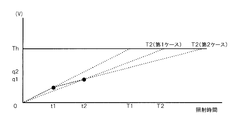
ここで、残りの照射時間Δtまたは適正照射時間Tを求める式について説明する。図5Bは、残りの照射時間Δtまたは適正照射時間Tの求め方を説明するための図である。
tは照射開始からの時間なので既知の値である。Thは上述の閾値Thresと同様に、放射線発生装置12の設置やメンテナンス時に調整し、関連技術のAECと同様に、一様露光で一定の出力で停止するように調整するので、既知の値である。また、各時刻での積算画素値q(digit)も電子カセッテ20で検出した値であるため既知の値である。
例えば、図5Bの場合には、t1秒でq1(digit)増加した訳だから、そのペースでTh(digit)になる時間Tは、以下の式で表される。
T1/t1=Th/q1より、
T1=(Th/q1)×t1となる。
T1/t1=Th/q1より、
T1=(Th/q1)×t1となる。
T2以降の決め方はいくつかあるが2通り説明する。まず、第1ケースとしてそれまでの全積分量q2とそれまでの全照射時間t2から、T1と同じように求めると、
T2=(Th/q2)×t2
となる。
T2=(Th/q2)×t2
となる。
他の方法(第2ケース)では、t1からt2までの変化分から計算する。この場合には以下の式となる。
(T2-t1)/(t2-t1)=(Th-q1)/(q2-q1)より、
T2=t1+(Th-q1)×(t2-t1)/(q2-q1)となる。
T2=t1+(Th-q1)×(t2-t1)/(q2-q1)となる。
T3、T4以降も同様に求めることができる。AEC用I/F26側と違って、電子カセッテ20側は無線切断による情報ロスがないので、毎回更新される。
なお、電圧増加θをAEC用I/F26側ではなく、電子カセッテ20側で計算する方法もある。しかしながら、電子カセッテ20側で電圧増加θを計算する場合には、無線が一部届かないことがあったときには、AEC用I/F26側で計算していないので、傾きを修正する手段がなく誤差が大きくなってしまうため、電圧増加θはAEC用I/F26側で計算する方が好ましい。
また、適正照射時間Tを電子カセッテ20側ではなく、AEC用I/F26側で計算する方法もあるが、その場合には、画素値qと照射時間tの対を送ってやればよい。この方法なら傾きを常に修正可能である。この場合には、電子カセッテ20側では画素値(digit)と時間、AEC用I/F26側で電圧と時間を扱うように分けた方が仕組み上わかりやすくなる。
続いて、上述のように構成された本実施の形態に係わる放射線撮影システム10のAEC用I/F26で行われる具体的な処理について説明する。図6は、本実施の形態に係わる放射線画像撮影システム10のAEC用I/F26で行われる処理の流れの一例を示すフローチャートである。
ステップ100では、電子カセッテ20からデジタルのAEC信号を受信してステップ102へ移行する。すなわち、電子カセッテ20から出力されるデジタルの照射停止予告信号をAEC信号受信部70が受信する。
ステップ102では、AEC信号変換部72によってデジタルの照射停止予告信号をアナログの線量を表す信号に変換する処理(AEC信号変換処理)が行われてステップ104へ移行する。すなわち、上述のように、照射開始から今までの照射時間tと、電子カセッテ20で計算された適正照射時間Tに対する残りの照射時間Δt(=T-t)と、を表すデジタルの照射停止予告信号を、アナログの単位時間あたりの電圧増加θ(V/sec)に変換する処理を行って、求めた単位時間あたりの電圧増加θを時間積分することにより、放射線の照射量に対応する電圧を表すアナログ信号を求めてステップ104へ移行する。
ステップ104では、変換したアナログ信号(電圧信号)を放射線発生装置12の放射線照射制御部23へ出力してステップ106へ移行する。これによって、放射線照射制御部23では、関連技術のAECと同様に、放射線の照射量が所定量に達したところで放射線の照射を停止することができる。
ステップ106では、AEC信号を受信したか否か判定され、該判定が肯定された場合にはステップ100に戻って上述の処理が繰り返され、判定が否定された場合には一連の処理を終了する。なお、該判定は、次のAEC信号を受信したか否かを判定するが、無線の状況によっては照射停止線量になっていないのに次のAEC信号を受信しない場合があるので、単位時間あたりの電圧増加θが閾値Thresに達していない場合には、次のAEC信号を受信するまで待機する。また、閾値Thresに達していないのに次のAEC信号を受信しない時間が予め定めた時間以上経過した場合にはエラー処理(エラー報知等)等を行うようにしてもよい。
このように、本実施の形態の放射線撮影システム10では、電子カセッテ20から出力されるデジタルの照射停止予告信号をAEC用I/F26によって線量を表すアナログ信号に変換して出力するようにしたので、無線通信によって飛び飛びで受信される離散的な線量情報の間を補完推定することができ、照射停止の精度を向上することができる。すなわち照射量情報を受信した時には既に必要な累積値をオーバーしてしまっている、ということを防ぐことができ照射停止の精度が良い。
また、関連技術のイオンチャンバ34等を利用したAEC制御を行うシステムをそのまま利用して電子カセッテ20を利用することができる。また、関連技術のシステムを利用することができるため、電子カセッテ20が故障などによって使用不可能な場合には、関連技術のカセッテを使用することもできる。
すなわち、アナログ信号を受け取るインタフェースが多くの放射線発生装置側にあるために、本実施の形態のようにAEC用I/F26によってアナログ信号に変化するようにすることで、様々な種類の放射線発生装置と接続可能になり、関連技術のシステムに放射線の照射量を検出する電子カセッテ20を適用することができる。
電子カセッテ20から送られる照射停止予告信号の送信頻度を少なくすればするほどネットワーク環境に与える通信負荷が少なくて済む。通信負荷が少ないということは1回1回の無線通信の遅延も生じ難いということであり、システム品質が安定する利点が大きい。しかしながら、関連技術のデジタルのAEC信号で照射制御する仕組みだと、送信頻度を少なくすればするほどあるタイミングで累積量がオーバーしてしまった時のオーバー量が大きくなってしまう。一方で本実施形態のようにアナログ信号に変換することで、通信頻度を抑えて通信品質を安定させつつ、オーバー量をミニマム化することができる。
なお、本実施の形態では、AEC用I/F26がデジタルの照射停止予告信号を放射線の照射量に対応する電圧を表すアナログ信号(電圧信号)に変換するようにしたが、照射量に対応する電流を表すアナログ信号(電流信号)に変換するようにしてもよい。
また、本実施の形態における放射線は、特に限定されるものではなく、X線やγ線等を適用することができる。
また、上記の実施の形態におけるフローチャートで示した処理は、プログラムとして各種記憶媒体に記憶して流通するようにしてもよい。
その他、本実施の形態で説明した放射線画像撮影システム10、放射線発生装置12、電子カセッテ20等の構成、動作等は一例であり、本発明の主旨を逸脱しない範囲内において状況に応じて変更可能である。
日本出願2012-242997の開示はその全体が参照により本明細書に取り込まれる。本明細書に記載された全ての文献、特許出願、および技術規格は、個々の文献、特許出願、および技術規格が参照により取り込まれることが具体的かつ個々に記された場合と同程度に、本明細書中に参照により取り込まれる。
Claims (16)
- 照射された放射線に応じた画像を撮影すると共に、放射線の照射量を検出して検出結果を表す信号を出力する放射線撮影装置から前記検出結果を表す信号をデジタル信号で受信する受信手段と、
前記受信手段によって受信した前記検出結果を表すデジタル信号を、放射線を前記放射線撮影装置に照射すると共に放射線が所定照射量になった場合に放射線の照射を停止する放射線照射装置が認識可能なアナログ信号に変換する変換手段と、
を備えた放射線信号処理装置。 - 前記受信手段は、無線通信により前記デジタル信号を受信し、
前記変換手段は、前記アナログ信号を有線接続された前記放射線照射装置に更に出力する、
請求項1に記載の放射線信号処理装置。 - 前記受信手段は、放射線照射開始からの照射時間と、予め定めた適正照射時間に対する残りの照射時間とを表す照射停止予告信号を前記デジタル信号として受信する、
請求項1又は請求項2に記載の放射線信号処理装置。 - 前記受信手段は、放射線照射開始からの照射時間と、予め定めた適正照射時間に対する残りの照射時間と、時間の単位とを表す照射停止予告信号を前記デジタル信号として受信する請求項1又は請求項2に記載の放射線信号処理装置。
- 前記変換手段は、前記デジタル信号から単位時間あたりの電圧増加を求めて、時間積分することにより、放射線の照射量に対応する電圧を表すアナログ信号に変換する請求項3又は請求項4に記載の放射線信号処理装置。
- 前記変換手段が、最新の前記デジタル信号に基づいて単位時間あたりの電圧増加を求める請求項5に記載の放射線信号処理装置。
- 前記放射線撮影装置は、線量が多くなり即停止する場合に前記電圧増加が最大となる前記照射停止予告信号を前記デジタル信号として送信する請求項5又は請求項6に記載の放射線信号処理装置。
- 照射された放射線の線量を検出して出力する機能を備えて、放射線画像の撮影を行う放射線画像撮影装置と、
請求項1~7の何れか1項に記載の放射線信号処理装置と、
を備えた放射線撮影システム。 - (a)照射された放射線に応じた画像を撮影すると共に、放射線の照射量を検出して検出結果を表す信号を出力する放射線撮影装置から前記検出結果を表す信号をデジタル信号で受信手段によって受信し、
(b)(a)で受信した前記検出結果を表すデジタル信号を、放射線を前記放射線撮影装置に照射すると共に放射線が所定照射量になった場合に放射線の照射を停止する放射線照射装置が認識可能なアナログ信号に変換手段によって変換する、
放射線信号処理方法。 - (a)は、無線通信により前記デジタル信号を受信し、
(b)は、前記アナログ信号を有線接続された前記放射線照射装置に更に出力する、
請求項9に記載の放射線信号処理方法。 - (a)は、放射線照射開始からの照射時間と、予め定めた適正照射時間に対する残りの照射時間とを表す照射停止予告信号を前記デジタル信号として受信する請求項9又は請求項10に記載の放射線信号処理方法。
- (a)は、放射線照射開始からの照射時間と、予め定めた適正照射時間に対する残りの照射時間と、時間の単位とを表す照射停止予告信号を前記デジタル信号として受信する請求項9又は請求項10に記載の放射線信号処理方法。
- (b)は、前記検出結果から単位時間あたりの電圧増加を求めて、時間積分することにより、放射線の照射量に対応する電圧を表すアナログ信号に変換する請求項11又は請求項12に記載の放射線信号処理方法。
- 前記変換手段が、最新の前記デジタル信号に基づいて単位時間あたりの電圧増加を求める請求項13に記載の放射線信号処理方法。
- 線量が多くなり即停止する場合に前記電圧増加が最大となる前記照射停止予告信号を前記デジタル信号として送信する請求項13又は請求項14に記載の放射線信号処理方法。
- コンピュータに放射線信号処理プロセスを実行させるためのプログラムを記憶したコンピュータ可読記録媒体であって、
前記放射線信号処理プロセスは、
(a)照射された放射線に応じた画像を撮影すると共に、放射線の照射量を検出して検出結果を表す信号を出力する放射線撮影装置から前記検出結果を表す信号をデジタル信号を受信し、
(b)(a)で受信した前記検出結果を表すデジタル信号を、放射線を前記放射線撮影装置に照射すると共に放射線が所定照射量になった場合に放射線の照射を停止する放射線照射装置が認識可能なアナログ信号に変換する、
ことを含む、コンピュータ可読記録媒体。
Priority Applications (2)
| Application Number | Priority Date | Filing Date | Title |
|---|---|---|---|
| CN201380056375.3A CN104768464B (zh) | 2012-11-02 | 2013-09-26 | 放射线信号处理装置、放射线图像摄影系统及放射线信号处理方法 |
| US14/692,746 US9674935B2 (en) | 2012-11-02 | 2015-04-22 | Radiation signal processing device, radiation imaging system, and radiation signal processing method |
Applications Claiming Priority (2)
| Application Number | Priority Date | Filing Date | Title |
|---|---|---|---|
| JP2012242997A JP6004898B2 (ja) | 2012-11-02 | 2012-11-02 | 放射線信号処理装置、放射線画像撮影システム、放射線信号処理方法、及び放射線信号処理プログラム |
| JP2012-242997 | 2012-11-02 |
Related Child Applications (1)
| Application Number | Title | Priority Date | Filing Date |
|---|---|---|---|
| US14/692,746 Continuation US9674935B2 (en) | 2012-11-02 | 2015-04-22 | Radiation signal processing device, radiation imaging system, and radiation signal processing method |
Publications (1)
| Publication Number | Publication Date |
|---|---|
| WO2014069129A1 true WO2014069129A1 (ja) | 2014-05-08 |
Family
ID=50627045
Family Applications (1)
| Application Number | Title | Priority Date | Filing Date |
|---|---|---|---|
| PCT/JP2013/076131 Ceased WO2014069129A1 (ja) | 2012-11-02 | 2013-09-26 | 放射線信号処理装置、放射線画像撮影システム、及び放射線信号処理方法 |
Country Status (4)
| Country | Link |
|---|---|
| US (1) | US9674935B2 (ja) |
| JP (1) | JP6004898B2 (ja) |
| CN (1) | CN104768464B (ja) |
| WO (1) | WO2014069129A1 (ja) |
Families Citing this family (4)
| Publication number | Priority date | Publication date | Assignee | Title |
|---|---|---|---|---|
| JP6021403B2 (ja) * | 2012-04-19 | 2016-11-09 | キヤノン株式会社 | 放射線撮像装置 |
| JP6706136B2 (ja) * | 2016-04-28 | 2020-06-03 | キヤノン株式会社 | 放射線撮像装置、放射線撮像システム、放射線撮像方法およびプログラム |
| WO2020056614A1 (en) * | 2018-09-19 | 2020-03-26 | Shenzhen Xpectvision Technology Co., Ltd. | A radiation detector with automatic exposure control and a method of automatic exposure control |
| JP7551697B2 (ja) * | 2022-06-28 | 2024-09-17 | キヤノン株式会社 | 放射線撮影システム、放射線撮像装置、および放射線撮影システムの制御方法 |
Citations (3)
| Publication number | Priority date | Publication date | Assignee | Title |
|---|---|---|---|---|
| JPH04105477A (ja) * | 1990-08-27 | 1992-04-07 | Hitachi Medical Corp | X線画像診断装置 |
| JP2008117641A (ja) * | 2006-11-06 | 2008-05-22 | Shimadzu Corp | X線撮影装置 |
| JP2012073230A (ja) * | 2010-08-31 | 2012-04-12 | Fujifilm Corp | 放射線撮影装置、及び放射線撮影システム |
Family Cites Families (11)
| Publication number | Priority date | Publication date | Assignee | Title |
|---|---|---|---|---|
| US4322619A (en) * | 1979-11-09 | 1982-03-30 | University Of Utah | Optical masking radiography |
| US6399950B1 (en) * | 2000-11-27 | 2002-06-04 | Shimadzu Corporation | Two-dimensional radiation detector |
| JP2006263339A (ja) | 2005-03-25 | 2006-10-05 | Konica Minolta Medical & Graphic Inc | 画像取得装置及び画像取得システム |
| JP4713952B2 (ja) * | 2005-06-02 | 2011-06-29 | 株式会社東芝 | X線透視撮影用自動露出制御装置 |
| US7313224B1 (en) * | 2006-06-22 | 2007-12-25 | General Electric Co. | Wireless integrated automatic exposure control module |
| JP2009034428A (ja) * | 2007-08-03 | 2009-02-19 | Konica Minolta Medical & Graphic Inc | X線撮影システム |
| JP5068128B2 (ja) * | 2007-09-28 | 2012-11-07 | 富士フイルム株式会社 | 放射線画像撮影装置 |
| CN100581475C (zh) * | 2008-03-04 | 2010-01-20 | 西安交通大学 | 一种医用x射线ccd型数字摄像机 |
| JP5151676B2 (ja) * | 2008-05-20 | 2013-02-27 | コニカミノルタエムジー株式会社 | 放射線画像撮影システム |
| US8873712B2 (en) * | 2010-04-13 | 2014-10-28 | Carestream Health, Inc. | Exposure control using digital radiography detector |
| CN202143287U (zh) * | 2011-06-02 | 2012-02-08 | 赵建国 | X线曝光控制设备及x线曝光系统 |
-
2012
- 2012-11-02 JP JP2012242997A patent/JP6004898B2/ja active Active
-
2013
- 2013-09-26 CN CN201380056375.3A patent/CN104768464B/zh active Active
- 2013-09-26 WO PCT/JP2013/076131 patent/WO2014069129A1/ja not_active Ceased
-
2015
- 2015-04-22 US US14/692,746 patent/US9674935B2/en active Active
Patent Citations (3)
| Publication number | Priority date | Publication date | Assignee | Title |
|---|---|---|---|---|
| JPH04105477A (ja) * | 1990-08-27 | 1992-04-07 | Hitachi Medical Corp | X線画像診断装置 |
| JP2008117641A (ja) * | 2006-11-06 | 2008-05-22 | Shimadzu Corp | X線撮影装置 |
| JP2012073230A (ja) * | 2010-08-31 | 2012-04-12 | Fujifilm Corp | 放射線撮影装置、及び放射線撮影システム |
Also Published As
| Publication number | Publication date |
|---|---|
| US9674935B2 (en) | 2017-06-06 |
| CN104768464B (zh) | 2018-12-18 |
| US20150230324A1 (en) | 2015-08-13 |
| JP6004898B2 (ja) | 2016-10-12 |
| CN104768464A (zh) | 2015-07-08 |
| JP2014090868A (ja) | 2014-05-19 |
Similar Documents
| Publication | Publication Date | Title |
|---|---|---|
| CN101849834B (zh) | 放射线成像设备及其暗电流校正方法 | |
| CN103841891B (zh) | 放射线摄影系统及其控制方法以及放射线图像检测装置 | |
| JP6326562B2 (ja) | X線システム | |
| JP6890443B2 (ja) | 放射線撮影システム、放射線撮影方法、及びプログラム | |
| CN102551752A (zh) | 辐射图像检测设备和用于控制辐射图像检测设备的方法 | |
| CN102525506A (zh) | 射线图像检测设备及其控制方法 | |
| JP6004898B2 (ja) | 放射線信号処理装置、放射線画像撮影システム、放射線信号処理方法、及び放射線信号処理プログラム | |
| CN104605873A (zh) | X射线摄像设备以及控制x射线摄像的控制设备和方法 | |
| JP2021137271A (ja) | 放射線撮影システム及びその制御方法、並びに、制御装置 | |
| EP3266376A1 (en) | Radiographing system, dose index management method, and storage medium | |
| JP2011067543A (ja) | 放射線制御装置及び放射線撮影システム、並びに撮影条件設定方法 | |
| JP2014161454A (ja) | 放射線画像撮影装置及びその制御方法、並びにプログラム | |
| JP2010197679A (ja) | 放射線画像取得システム及び放射線画像検出カセッテ | |
| JP6433113B2 (ja) | 放射線撮影装置、放射線撮影システム、制御方法、及びプログラム。 | |
| JP6944268B2 (ja) | 放射線撮影装置、放射線撮影システム、放射線撮影装置の制御方法及びプログラム | |
| JP2014090869A (ja) | 放射線信号処理装置、放射線画像撮影システム、放射線信号処理方法、及び放射線信号処理プログラム | |
| JP2006026283A (ja) | 放射線撮影システム | |
| US10498974B2 (en) | Radiation image capturing apparatus and radiation image capturing system | |
| CN108720854B (zh) | 放射线照射检测系统及放射线产生装置 | |
| JP2017094011A (ja) | 放射線撮影装置、放射線撮影システム、および放射線撮影装置の制御方法。 | |
| JP2008142093A (ja) | 放射線画像撮影システム及び放射線画像撮影用カセッテ | |
| JP2011098025A (ja) | 放射線画像生成システム | |
| JP2006122121A (ja) | 放射線画像撮影システム | |
| JP2009077891A (ja) | 放射線画像撮影用カセッテ | |
| JP2010119513A (ja) | X線撮影システム |
Legal Events
| Date | Code | Title | Description |
|---|---|---|---|
| 121 | Ep: the epo has been informed by wipo that ep was designated in this application |
Ref document number: 13850125 Country of ref document: EP Kind code of ref document: A1 |
|
| NENP | Non-entry into the national phase |
Ref country code: DE |
|
| 122 | Ep: pct application non-entry in european phase |
Ref document number: 13850125 Country of ref document: EP Kind code of ref document: A1 |