WO2014064962A1 - カメラモジュール及びチタン銅箔 - Google Patents
カメラモジュール及びチタン銅箔 Download PDFInfo
- Publication number
- WO2014064962A1 WO2014064962A1 PCT/JP2013/066983 JP2013066983W WO2014064962A1 WO 2014064962 A1 WO2014064962 A1 WO 2014064962A1 JP 2013066983 W JP2013066983 W JP 2013066983W WO 2014064962 A1 WO2014064962 A1 WO 2014064962A1
- Authority
- WO
- WIPO (PCT)
- Prior art keywords
- spring member
- camera module
- lens
- concentration
- mass
- Prior art date
- Legal status (The legal status is an assumption and is not a legal conclusion. Google has not performed a legal analysis and makes no representation as to the accuracy of the status listed.)
- Ceased
Links
Images


Classifications
-
- G—PHYSICS
- G02—OPTICS
- G02B—OPTICAL ELEMENTS, SYSTEMS OR APPARATUS
- G02B7/00—Mountings, adjusting means, or light-tight connections, for optical elements
- G02B7/02—Mountings, adjusting means, or light-tight connections, for optical elements for lenses
- G02B7/04—Mountings, adjusting means, or light-tight connections, for optical elements for lenses with mechanism for focusing or varying magnification
- G02B7/09—Mountings, adjusting means, or light-tight connections, for optical elements for lenses with mechanism for focusing or varying magnification adapted for automatic focusing or varying magnification
-
- C—CHEMISTRY; METALLURGY
- C22—METALLURGY; FERROUS OR NON-FERROUS ALLOYS; TREATMENT OF ALLOYS OR NON-FERROUS METALS
- C22C—ALLOYS
- C22C9/00—Alloys based on copper
-
- C—CHEMISTRY; METALLURGY
- C22—METALLURGY; FERROUS OR NON-FERROUS ALLOYS; TREATMENT OF ALLOYS OR NON-FERROUS METALS
- C22F—CHANGING THE PHYSICAL STRUCTURE OF NON-FERROUS METALS AND NON-FERROUS ALLOYS
- C22F1/00—Changing the physical structure of non-ferrous metals or alloys by heat treatment or by hot or cold working
- C22F1/08—Changing the physical structure of non-ferrous metals or alloys by heat treatment or by hot or cold working of copper or alloys based thereon
-
- G—PHYSICS
- G02—OPTICS
- G02B—OPTICAL ELEMENTS, SYSTEMS OR APPARATUS
- G02B7/00—Mountings, adjusting means, or light-tight connections, for optical elements
- G02B7/02—Mountings, adjusting means, or light-tight connections, for optical elements for lenses
- G02B7/04—Mountings, adjusting means, or light-tight connections, for optical elements for lenses with mechanism for focusing or varying magnification
- G02B7/08—Mountings, adjusting means, or light-tight connections, for optical elements for lenses with mechanism for focusing or varying magnification adapted to co-operate with a remote control mechanism
-
- G—PHYSICS
- G03—PHOTOGRAPHY; CINEMATOGRAPHY; ANALOGOUS TECHNIQUES USING WAVES OTHER THAN OPTICAL WAVES; ELECTROGRAPHY; HOLOGRAPHY
- G03B—APPARATUS OR ARRANGEMENTS FOR TAKING PHOTOGRAPHS OR FOR PROJECTING OR VIEWING THEM; APPARATUS OR ARRANGEMENTS EMPLOYING ANALOGOUS TECHNIQUES USING WAVES OTHER THAN OPTICAL WAVES; ACCESSORIES THEREFOR
- G03B3/00—Focusing arrangements of general interest for cameras, projectors or printers
- G03B3/10—Power-operated focusing
-
- Y—GENERAL TAGGING OF NEW TECHNOLOGICAL DEVELOPMENTS; GENERAL TAGGING OF CROSS-SECTIONAL TECHNOLOGIES SPANNING OVER SEVERAL SECTIONS OF THE IPC; TECHNICAL SUBJECTS COVERED BY FORMER USPC CROSS-REFERENCE ART COLLECTIONS [XRACs] AND DIGESTS
- Y10—TECHNICAL SUBJECTS COVERED BY FORMER USPC
- Y10T—TECHNICAL SUBJECTS COVERED BY FORMER US CLASSIFICATION
- Y10T428/00—Stock material or miscellaneous articles
- Y10T428/12—All metal or with adjacent metals
- Y10T428/12431—Foil or filament smaller than 6 mils
Definitions
- the present invention relates to a camera module and titanium copper foil.
- a camera module that employs this type of lens drive system has a spring member such as a compression coil spring or a leaf spring that elastically biases the lens toward the initial position in the optical axis direction, and an electromagnetic force that resists the biasing force of the spring member.
- Electromagnetic drive means including a coil and a magnet that are generated and can drive the lens in the optical axis direction, and control means for moving the lens to a predetermined position by controlling a drive current supplied to the electromagnetic drive means are provided. Yes. The operation principle will be briefly described. When the coil of the electromagnetic drive means is not energized, the spring member holds the lens in the initial position, but when a drive current is supplied from the power source to the coil of the electromagnetic drive means.
- Electromagnetic force against the urging force of the spring member is generated, and the coil moves integrally with the lens in the optical axis direction. Therefore, an autofocus operation of moving the lens to a desired position on the optical axis can be performed by controlling the magnitude of the drive current by the control means.
- the spring member is proportional to the elasticity.
- the present invention has been made in view of the actual situation of the prior art, and an object of the present invention is to suppress the sag of a spring member, and to prevent camera malfunction and titanium even when an impact such as dropping is applied. To provide copper foil.
- Titanium copper is C1990 (JIS registered alloy, 3.2 mass% Ti-residual Cu), NKT322 (developed alloy of XX Nippon Mining & Metals Co., Ltd., 3.2 mass% Ti-0.2 mass% Fe-residue It has been put to practical use as Cu) and the like, and has high proof stress and excellent stress relaxation characteristics.
- the present inventors can improve the sag characteristics of the titanium copper foil by controlling the Vickers hardness of the titanium copper foil or the composition of the extreme surface of the titanium copper foil within an appropriate range, and are suitably used as a spring member of the camera module. I found out that I can do it.
- the present invention completed on the basis of the above knowledge is a lens, a spring member that elastically biases the lens to an initial position in the optical axis direction, and an electromagnetic force that resists the biasing force of the spring member.
- a camera module comprising an electromagnetic drive means capable of driving in the optical axis direction and a control means for controlling a drive current supplied to the electromagnetic drive means, wherein the spring member is 2.9 to 3.5% by mass. It contains Ti, the balance is made of copper and inevitable impurities, has a Vickers hardness of 350 or more, and has a thickness of 0.01 mm or more and less than 0.1 mm.
- a lens, a spring member that elastically biases the lens to an initial position in the optical axis direction, and an electromagnetic force that resists the biasing force of the spring member are generated to drive the lens in the optical axis direction.
- a camera module comprising a possible electromagnetic drive means and a control means for controlling a drive current supplied to the electromagnetic drive means, wherein the spring member contains 2.9 to 3.5% by mass of Ti, and the balance Consists of copper and inevitable impurities, the Ti concentration at a depth of 0.1 ⁇ m from the surface is 0.6 times or more of the Ti concentration at a depth of 1 ⁇ m from the surface, and the thickness is 0.01 mm or more and 0 Less than 1 mm.
- the lens, a spring member that elastically biases the lens to an initial position in the optical axis direction, and an electromagnetic force that resists the biasing force of the spring member are generated to cause the lens to move in the optical axis direction.
- a camera module comprising a drivable electromagnetic drive means and a control means for controlling a drive current supplied to the electromagnetic drive means, wherein the spring member contains 2.9 to 3.5% by mass of Ti, The balance is made of copper and inevitable impurities, has a Vickers hardness of 350 or more, and the Ti concentration at a depth of 0.1 ⁇ m from the surface is 0.6 times the Ti concentration at a depth of 1 ⁇ m from the surface And the thickness is 0.01 mm or more and less than 0.1 mm.
- a camera module that performs an autofocus operation by moving a lens with an electromagnetic force that resists a biasing force of a spring member, wherein the spring member has a mass of 2.9 to 3.5 mass. % Ti, the balance is made of copper and inevitable impurities, has a Vickers hardness of 350 or more, and a thickness of 0.01 mm or more and less than 0.1 mm.
- a camera module that performs an autofocus operation by moving a lens with an electromagnetic force that resists a biasing force of a spring member, wherein the spring member has a mass of 2.9 to 3.5 mass. % Ti, the balance is made of copper and inevitable impurities, and the Ti concentration at a depth of 0.1 ⁇ m from the surface is not less than 0.6 times the Ti concentration at a depth of 1 ⁇ m from the surface, The thickness is 0.01 mm or more and less than 0.1 mm.
- a camera module that performs an autofocus operation by moving a lens with an electromagnetic force that resists a biasing force of a spring member, wherein the spring member has a mass of 2.9 to 3.5 mass.
- % Ti the balance is made of copper and inevitable impurities, has a Vickers hardness of 350 or more, and the Ti concentration at a depth of 0.1 ⁇ m from the surface is Ti at a depth of 1 ⁇ m from the surface.
- the density is 0.6 times or more and the thickness is 0.01 mm or more and less than 0.1 mm.
- the spring member further contains 0.17 to 0.23 mass% Fe.
- 2.9 to 3.5% by mass of Ti is contained, the balance is made of copper and inevitable impurities, the Vickers hardness is 350 or more, and the thickness is 0.8. It is a titanium copper foil which is 01 mm or more and less than 0.1 mm.
- the titanium copper foil has a Ti concentration of 0.6 times or more at a position 1 ⁇ m deep from the surface and a thickness of 0.01 mm or more and less than 0.1 mm.
- the remainder is made of copper and inevitable impurities, has a Vickers hardness of 350 or more, and is 0.1 ⁇ m from the surface.
- the titanium copper foil has a Ti concentration at a depth position of 0.6 or more times the Ti concentration at a depth of 1 ⁇ m from the surface and a thickness of 0.01 mm or more and less than 0.1 mm.
- the titanium copper foil according to the present invention further contains 0.17 to 0.23 mass% Fe.
- the present invention it is possible to provide a camera module and a titanium copper foil that can suppress the sag of the spring member and hardly cause malfunction even when an impact such as dropping is applied.
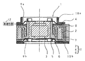
- FIG. 2 is a cross-sectional view illustrating an example of the operation of the camera module in FIG. 1.
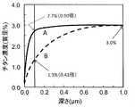
- It is a graph showing the change of Ti concentration of the depth direction of the titanium copper foil (solid line) which concerns on embodiment of this invention, and the conventional titanium copper foil (dotted line).
- It is a graph which shows the relationship between the total processing degree (r) of the spring member suitable for the camera module which concerns on embodiment of this invention, and Vickers hardness.
- r total processing degree
- Vickers hardness It is a graph showing the relationship between Vickers hardness and P value when the foil thickness of the spring member which concerns on embodiment of this invention is 0.028 mm.
- It is a graph showing the relationship between Vickers hardness and P value when the foil thickness of the spring member which concerns on embodiment of this invention is 0.052 mm.
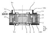
- the camera module 1 includes a lens 3, spring members 9 a and 9 b that elastically urge the lens 3 to an initial position in the optical axis direction, a spring member 9 a, Electromagnetic driving means 11 (yoke 2, magnet 4 and coil 6) capable of driving the lens 3 in the optical axis direction by generating an electromagnetic force against the urging force of 9b, and a driving current supplied to the electromagnetic driving means 11 And control means 12 for controlling.
- Electromagnetic driving means 11 (yoke 2, magnet 4 and coil 6) capable of driving the lens 3 in the optical axis direction by generating an electromagnetic force against the urging force of 9b, and a driving current supplied to the electromagnetic driving means 11
- control means 12 for controlling.
- the lens 3 is accommodated in the carrier 5.
- the carrier 5 is a molded product made of a synthetic resin or the like having a cylindrical structure with a bottom surface, and holds the lens 3 at the center position.
- a pre-formed coil 6 is bonded on the outer peripheral surface of the carrier 5.
- a magnet 4 is disposed on the outer side of the coil 6. The magnet 4 is magnetized in the radial direction.
- the magnet 4 is accommodated in the yoke 2.
- the yoke 2 is a magnetic material such as soft iron, has a U-shaped cylindrical shape with a closed upper surface portion, and has a cylindrical inner wall 2a and an outer wall 2b.
- the magnet 4 and the coil 6 are disposed in a space provided between the inner wall 2a and the outer wall 2b.
- the yoke 2 is mounted on a base 7 made of a resin molded product or the like.
- the coil 6, the magnet 4, and the yoke 2 function as electromagnetic driving means 11 of the camera module 1. That is, when a drive current is supplied to the coil 6, a predetermined electromagnetic force is generated by the magnet 4 and the yoke 2 against the urging force of the spring members 9a and 9b.
- a frame 8 composed of a resin molded product or the like disposed so as to cover the yoke 2 is disposed.
- a cap 10 b is attached to the bottom surface of the base 7.
- a cap 10 a is attached to the upper part of the frame 8.
- the spring members 9a and 9b are the same product, support the carrier 5 sandwiched from both ends in the same positional relationship, and function as a power feeding path to the coil 6.
- One lead wire of the coil 6 extends upward through a groove provided on the inner peripheral surface of the carrier 5 and is soldered to the spring member 9a.
- the other lead wire of the coil 6 extends downward through a groove provided on the bottom surface of the carrier 5 and is soldered to the spring member 9b.
- the spring member 9 a is fixed to the bottom portion of the carrier 5 and the base 7, and the spring member 9 a is fixed to the uppermost portion of the carrier 5 and the frame 8.
- Each of the spring members 9a and 9b has an outermost peripheral portion fixed to the frame 8 and the base 7, respectively, and a notch groove portion for each inner peripheral portion of 120 ° is fitted to the carrier 5 and fixed by heat caulking or the like.
- the spring member 9b and the base 7, and the spring member 9a and the frame 8 are fixed by adhesion, heat caulking, or the like.
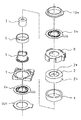
- the spring members 9a and 9b have the same shape, and are attached in the same positional relationship as shown in FIGS. 1 and 2, so that the axial displacement when the carrier 5 moves upward can be suppressed. it can. Since the coil 6 is manufactured by pressure molding after winding, the accuracy of the finished outer diameter is improved, and the coil 6 can be easily arranged in a predetermined narrow gap. Since the carrier 5 hits the base 7 at the lowermost position and hits the yoke 2 at the uppermost position, a carrier mechanism is provided in the vertical direction to prevent the carrier 5 from dropping off.
- a plate spring made of improved titanium copper foil is used as a material of the spring members 9a and 9b.
- This titanium copper foil contains 2.9 to 3.5% by mass of Ti and optionally 0.17 to 0.23% by mass of Fe, and the balance is made of copper and inevitable impurities, and more than 350 It has Vickers hardness, or on the titanium copper foil surface, the Ti concentration at a depth of 0.1 ⁇ m from the surface is 0.6 times or more of the Ti concentration at a depth of 1 ⁇ m from the surface.
- the control means 12 is electrically connected to the spring members 9a and 9b, the coil 6 connected to the spring members 9a and 9b, and the power supply means (not shown), and is supplied to the coil 6 and supplied to the coil 6. The magnitude of the drive current is controlled.
- FIG. 3 shows a cross-sectional view when a current is applied to the coil 6 to generate electromagnetic force and the carrier 5 provided with the lens 3 is moved upward.
- a predetermined drive current is supplied from the power source to the power supply terminals of the spring members 9 a and 9 b
- a current flows through the coil 6 connected to the power supply terminal, and an electromagnetic force upward in the drawing of FIG.
- the restoring force the urging force to the initial position
- the upward movement distance of the carrier 5 is a position where the electromagnetic force and the restoring force are balanced.
- the amount of movement of the carrier 5 is determined by the magnitude of the drive current applied to the coil 6.
- the magnet 4 has been described as having a cylindrical shape, the magnet 4 is not limited to this, and may be divided into three or four parts and magnetized in the radial direction, and this may be adhered and fixed to the inner surface of the outer wall 2b of the yoke 2.
- the present invention is not limited to the configuration of the camera module 1 shown in FIGS.
- a spring member of a general camera module capable of performing an autofocus operation by moving a lens with an electromagnetic force that resists the biasing force of the spring member the titanium copper foil according to the embodiment of the present invention and Of course, a spring member can be applied.
- the present invention includes various embodiments not described herein, and various modifications can be made without departing from the spirit of the present invention.
- Titanium copper improves strength and conductivity by dissolving Ti in a Cu matrix by solution treatment and dispersing fine precipitates in the alloy by aging treatment.
- Ti concentration is less than 2.9% by mass, precipitation of the precipitate is insufficient, and a desired strength cannot be obtained. If the Ti concentration exceeds 3.5% by mass, the bendability deteriorates. Further, in order to further improve the strength, 0.17 to 0.23% by mass of Fe can be contained.
- the chemical composition is standardized as JIS H 3130 (2006) with Ti: 2.9 to 3.5 mass% and Cu + Ti: 99.5 mass% or more. It is allowed to contain impurities of less than 0.5% by mass.
- titanium copper impurities include residual deoxidizers added to the molten metal (Al, Si, B, P, etc.), contamination from the furnace wall of the melting furnace and the molten metal coating (Al, Si, C, B, Na, Zr, Cr, etc.), impurities (Ag, etc.) contained in the main raw electrolytic copper at a relatively high concentration, contamination from scrap materials (S, etc.), contamination from atmospheric gases (O, N, etc.), etc. Is mentioned.
- the total amount of impurities is preferably 0.1% by mass, more preferably 0.05% by mass or less, and 0.01% by mass or less. Is more preferable.
- Hardness As the hardness increases, the proportionality limit increases and it becomes difficult for sag to occur. When the Vickers hardness is 350 or more, when used as a spring material for a camera module, a malfunction due to a drop impact is remarkably improved.
- the upper limit value of the Vickers hardness is not restricted from the viewpoint of the drop impact resistance, but the Vickers hardness of the titanium copper foil rarely exceeds 500.
- the strength (proportional limit) of the Ti-deficient layer is low compared to the part where the Ti concentration has not changed. Since the Ti-deficient layer is very thin, its influence on the material properties is difficult to detect in a tensile test or a hardness test, but may be manifested as a sag when a bending stress is applied. In bending deformation, the maximum stress is generated on the material surface, so that the sag characteristics due to bending are easily affected by the strength of the material surface layer. In addition, the thinner the material, the greater the influence of the Ti-deficient layer on the sag characteristics.
- the Ti concentration at a depth of 0.1 ⁇ m from the surface is adjusted to 0.6 times or more, more preferably 0.8 times or more of the Ti concentration at a depth of 1 ⁇ m from the surface, it is difficult for sag to occur. Thus, the malfunction due to the drop impact is remarkably improved.
- FIG. 4 shows the components of the titanium copper foil according to the embodiment of the present invention (product of the present invention) and the conventional titanium copper foil (conventional product) while being scraped by Ar sputtering using GDS (glow discharge emission spectroscopy).
- GDS low discharge emission spectroscopy
- the thickness of the titanium copper foil of the present invention is less than 0.1 mm, preferably 0.08 mm or less, more preferably 0.05 mm or less.
- the thickness of the titanium copper foil is less than 0.01 mm, the spring force as the spring material is insufficient.
- the spring members 9a and 9b of the autofocus module it is necessary to greatly deform the spring member in order to obtain a desired biasing force.
- the thickness of the titanium copper foil of the present invention is set to 0.01 mm or more, preferably 0.02 mm or more.
- Polishing for 5 to 300 seconds
- Polishing (6)
- Cold rolling (7) Aging treatment (350 to 550 ° C for 2 to 20 hours)
- Polishing (9)
- Cold rolling (10)
- Straightening annealing (300 to 600 ° C for 5 seconds to 10 hours)
- Hot rolling (1) can be performed under general titanium copper conditions.
- solution treatment (4) coarse Cu—Ti compound particles crystallized or precipitated during casting or hot rolling are dissolved in the Cu matrix.
- aging treatment (5) Cu 3 Ti or Cu 4 Ti fine particles are precipitated, and the strength of the alloy is increased by the fine precipitates.
- Cold rolling (6) and (9) is performed to increase the strength.
- the total workability (r) of cold rolling (6) and cold rolling (9) it is preferable to set the total workability (r) of cold rolling (6) and cold rolling (9) to 90% or higher.
- the strain relief annealing (10) is optionally performed in order to recover the spring limit value or the like that is lowered by the cold rolling when the cold rolling (9) is performed.
- Polishing (5), (8), and (11) are performed to remove the oxide scale on the surface generated in the heat treatments (4), (7), and (10).
- This polishing may be performed by chemical polishing or mechanical polishing. Further, chemical polishing and mechanical polishing may be used in combination.
- As the chemical polishing liquid a sulfuric acid-hydrogen peroxide solution, a ferric chloride solution, a cupric chloride solution, a nitric acid solution or the like having a strong corrosive power against Cu is used.
- a typical method of mechanical polishing is buffing using a rotary buff in which abrasive grains are embedded. *
- the surface oxidation of the material is most prominent in the solution treatment (4). This is due to the highest processing temperature. Therefore, in order to increase the Ti concentration at a depth of 0.1 ⁇ m from the surface, it is important to suppress the surface oxidation in the solution treatment (4). For this purpose, for example, the oxygen concentration in the heating furnace It is effective to reduce. Further, the Ti concentration at a position of a depth of 0.1 ⁇ m from the surface can also be increased by increasing the surface removal amount in the polishing (5).
- the titanium-copper of the present invention can be suitably used as a spring member for various parts other than the camera module, taking advantage of the feature that sag is unlikely to occur.
- electronic device parts such as a connector, a terminal, a socket, and a relay, are mentioned.
- C1990 and NKT322 alloys having compositions of C1990 and NKT322 (hereinafter, these alloys according to this example are described as C1990 and NKT322) are manufactured, and the hardness, surface composition, and foil thickness are camera modules.
- C1990 is an alloy registered in JIS H 3130 (2006), containing 2.9 to 3.5% by mass (typical value: 3.2% by mass) of Ti, with the balance being copper and inevitable Consists of impurities.
- NKT322 is an alloy developed by JX Nippon Mining & Metals Co., Ltd., 2.9 to 3.4 mass% (typical value 3.2 mass%) Ti and 0.17 to 0.23 mass%.
- Fe representsative value: 0.2% by mass), the balance being composed of copper and inevitable impurities.
- a rectangular parallelepiped ingot having a thickness of 150 mm and a width of 500 mm was manufactured by semi-continuous casting. This ingot was hot-rolled, heated at 950 ° C. for 3 hours, and then rolled to 10 mm. Next, in order to remove the oxide scale on the surface of the hot rolled sheet, the surface was chamfered. The thickness of the material after chamfering was 8 mm. Thereafter, cold rolling and heat treatment were performed in the order of the following steps to produce foils having thicknesses of 0.052 mm and 0.028 mm.
- Cold rolling 1 Cold rolling was performed to a predetermined thickness according to the target foil thickness and Vickers hardness.
- Solution treatment Heated at 800 ° C. for 10 seconds to 300 seconds. The heating time was appropriately adjusted so that the average diameter of the recrystallized grains after annealing was in the range of 5 to 20 ⁇ m. Furthermore, the heating atmosphere was changed to air, Ar, and CO, and the thickness of the oxide scale on the material surface, the Ti concentration immediately below the oxide scale, and the thickness of the Ti-deficient layer were adjusted.
- Polishing 1 After chemical polishing with a sulfuric acid-hydrogen peroxide solution, mechanical polishing was performed with a rotary buff to remove the oxide scale on the surface and the underlying material.
- the polishing depth of the surface was variously changed in the range of 0.3 to 1.0 ⁇ m depending on the concentration of the sulfuric acid-hydrogen peroxide solution and the duration of each polishing.
- Cold rolling 2 Cold rolling was performed to a predetermined thickness according to the target foil thickness and Vickers hardness.
- Aging treatment Heated at 450 ° C. for 5 hours in an Ar atmosphere.
- Polishing 2 After chemical polishing with a sulfuric acid-hydrogen peroxide solution, mechanical polishing was performed with a rotary buff to remove the oxide scale on the surface. The surface polishing depth was about 0.02 ⁇ m.
- Cold rolling 3 Rolled to the target foil thickness.
- the GDS analysis is performed on the surface of the foil sample that has been cold-rolled (7), and the Ti concentration ([% Ti] 0.1 ) at a depth of 0.1 ⁇ m from the surface and the position at a depth of 1 ⁇ m from the surface.
- Ti concentration ([% Ti] 1 ) was measured, and the titanium concentration ratio (R Ti ) on the surface defined by the following equation was obtained.
- R Ti [% Ti] 0.1 / [% Ti] 1
- micro Vickers hardness was measured in accordance with JIS Z 2244.
- FIG. 5 shows the relationship between the total degree of processing (r) and Vickers hardness. When R is 90% or more, a Vickers hardness of 350 or more is stably obtained.
- spring members 9a and 9b were manufactured using the foil sample after cold rolling, and the camera module 1 having the structure shown in FIGS. 1 to 3 was assembled.
- the camera module has the same structure.
- the current value (I Bmin ) when the carrier 5 starts moving and the current value (I Bmax ) when the moving amount of the carrier 5 is maximized were obtained.
- the camera module was dropped onto the floor from a height of 2 m, and the current value (I Amin ) when the carrier 5 started to move was measured for the camera module after dropping. From these measured values, the P value was determined by the following equation.
- P (%)
- the P value is a value obtained by dividing the change (absolute value) of the current at the start of movement due to dropping by the maximum current during movement.
Landscapes
- Physics & Mathematics (AREA)
- Chemical & Material Sciences (AREA)
- General Physics & Mathematics (AREA)
- Optics & Photonics (AREA)
- Engineering & Computer Science (AREA)
- Materials Engineering (AREA)
- Mechanical Engineering (AREA)
- Metallurgy (AREA)
- Organic Chemistry (AREA)
- Thermal Sciences (AREA)
- Crystallography & Structural Chemistry (AREA)
- Lens Barrels (AREA)
Abstract
Description
添付した図面を参照しながら本発明の実施の形態を説明する。以下の図面は模式的なものであり、厚みと平均寸法の関係、各層の厚みの比率等は現実のものとは異なることに留意すべきである。また、図面相互間においても互いの寸法の関係や比率が異なる部分が含まれていることは勿論である。また本明細書においては、説明の都合により「上」「下」の用語を適宜使用するが、これは図1又は図3における上下関係を指し、「上」はカメラから被写体に向う位置関係を表わす。
次に本発明に係るチタン銅箔について詳述する。
(合金成分)
Ti濃度は2.9~3.5質量%とする。チタン銅では、溶体化処理によりCuマトリックス中へTiを固溶させ、時効処理により微細な析出物を合金中に分散させることにより、強度及び導電率を向上させる。Ti濃度が2.9質量%未満になると、析出物の析出が不充分となり所望の強度が得られない。Ti濃度が3.5質量%を超えると、曲げ性が劣化する。また、強度を更に向上させるために、0.17~0.23質量%のFeを含有することができる。
チタン銅の代表的合金であるC1990の場合、その化学組成はJIS H 3130(2006年)において、Ti:2.9~3.5質量%、Cu+Ti:99.5質量%以上と規格化されており、0.5質量%未満の不純物を含有することが許容されている。チタン銅の不純物としては、例えば、溶湯に添加する脱酸剤の残留(Al、Si、B、P等)、溶解炉の炉壁や溶湯被覆剤からの混入(Al、Si、C、B、Na、Zr、Cr等)、主原料である電気銅が比較的高濃度で含有する不純物(Ag等)、スクラップ原料からの混入(S等)、雰囲気ガスからの混入(O、N等)等が挙げられる。本発明の効果をより良く発揮させるためには、不純物の総量は0.1質量%であることが好ましく、0.05質量%以下であることがより好ましく、0.01質量%以下であることがさらに好ましい。
硬さが上昇すると比例限界が高くなり、へたりが生じ難くなる。ビッカース硬さが350以上になると、カメラモジュールのばね材として用いた場合に、落下衝撃による動作不良が著しく改善される。ビッカース硬さの上限値は、耐落下衝撃特性の点からは規制されないが、チタン銅箔のビッカース硬さが500を超えることは少ない。
TiはCuと比較し著しく酸化しやすい。このため箔の製造プロセスにおいて、溶体化処理等の熱処理の際、高濃度のTiを含有する酸化スケールが材料表面に生成し、酸化スケール直下にTi濃度が母地より低い部分(以下、Ti欠乏層と称す)が生じる。これは高Tiの酸化スケールが成長する過程において、母地のTiが酸化スケール側に拡散(移動)するためである。その後、酸洗や機械研磨により酸化スケールを除去すると、箔表面にTi欠乏層が露呈する。
チタン銅箔の厚みが0.1mm以上になると、ばね部材9a、9bの付勢力が過大となり、レンズ駆動に必要な電磁力も増大する。その結果、カメラモジュールが大型化する、レンズの駆動精度が劣化する等の問題が生じる。
また、表面組成の制御により、チタン銅箔を板ばねとして用いたときのへたりが改善される効果は、箔厚が0.1mm未満になると発現し、箔が薄くなるほど顕著になる。同様に、ばね部材9a、9bに用いるチタン銅箔の表面組成制御により、オートフォーカスモジュールが落下衝撃を受けた際のばね部材のへたりが改善されオートフォーカスモジュールの動作不良が抑制される効果も、箔厚が0.1mm未満になると発現し、箔が薄くなるほど顕著になる。
そこで、本発明のチタン銅箔の厚みを0.1mm未満、好ましくは0.08mm以下、より好ましくは0.05mm以下とする。
一方、チタン銅箔の厚みが0.01mm未満になると、ばね材としてのばね力が不足する。特に、オートフォーカスモジュールのばね部材9a、9bとして用いる場合には、所望の付勢力を得るために、ばね部材により大きな変形を与えることが必要となる。その結果、落下衝撃を受けた際、ばね部材にへたりが発生しやすくなり、これはオートフォーカスモジュールの動作不良を招く。そこで、本発明のチタン銅箔の厚みを0.01mm以上、好ましくは0.02mm以上とする。
チタン銅箔の一般的な製造プロセスでは、まず溶解炉で電気銅、Ti等の原料を溶解し、所望の組成の溶湯を得る。そして、この溶湯をインゴットに鋳造する。チタンの酸化損耗を防止するため、溶解及び鋳造は真空中又は不活性ガス雰囲気中で行うことが好ましい。その後、次の順序で所望の厚み及び特性を有する箔に仕上げる。
(1)熱間圧延(温度800~1000℃、厚み5~20mm程度まで)
(2)面削(酸化スケール除去)
(3)冷間圧延
(4)溶体化処理(750~900℃で5~300秒間、水冷)
(5)研磨
(6)冷間圧延
(7)時効処理(350~550℃で2~20時間)
(8)研磨
(9)冷間圧延
(10)歪取り焼鈍(300~600℃で5秒~10時間)
(11)研磨
r(%)=(t0-t)/t0×100
(t0:研磨(5)の後の厚み、t:冷間圧延(9)の後の厚み)
本発明のチタン銅は、へたりが生じ難いという特徴を生かし、カメラモジュール以外の種々の部品のばね部材としても好適に使用することができる。例えば、コネクタ、端子、ソケット、リレー等の電子機器部品が挙げられる。
(2)溶体化処理:800℃で10秒間~300秒間加熱した。加熱時間は焼鈍後の再結晶粒の平均直径が5~20μmの範囲になるよう適宜調整した。さらに、加熱雰囲気を大気、Ar、COと変化させ、材料表面の酸化スケールの厚み、ならびに酸化スケール直下のTi濃度およびTi欠乏層の厚みを調整した。
(3)研磨1:硫酸-過酸化水素溶液により化学研磨した後、回転式バフにより機械研磨し、表面の酸化スケールおよびその直下の素地を除去した。その際、硫酸-過酸化水素溶液の濃度および各研磨の実施時間により、表面の研磨深さを0.3~1.0μmの範囲で種々変化させた。
(4)冷間圧延2:目標とする箔の厚みおよびビッカース硬さに応じ、所定の厚みまで冷間圧延した。
(5)時効処理:450℃で5時間、Ar雰囲気中で加熱した。
(6)研磨2:硫酸-過酸化水素溶液により化学研磨した後、回転式バフにより機械研磨し、表面の酸化スケールを除去した。表面の研磨深さは0.02μm程度であった。
(7)冷間圧延3:目標とする箔の厚みまで圧延した。
RTi=[%Ti]0.1/[%Ti]1
P(%)=|(IBmin-IAmin)|/IBmax×100
Claims (11)
- レンズと、
前記レンズを光軸方向の初期位置へ弾性付勢するばね部材と、
前記ばね部材の付勢力に抗する電磁力を生起して前記レンズを光軸方向へ駆動可能な電磁駆動手段と、
前記電磁駆動手段に供給される駆動電流を制御する制御手段と
を備えるカメラモジュールであって、
前記ばね部材が、2.9~3.5質量%のTiを含有し、残部が銅及び不可避的不純物からなり、350以上のビッカース硬さを有し、厚さが0.01mm以上0.1mm未満であることを特徴とするカメラモジュール。 - レンズと、
前記レンズを光軸方向の初期位置へ弾性付勢するばね部材と、
前記ばね部材の付勢力に抗する電磁力を生起して前記レンズを光軸方向へ駆動可能な電磁駆動手段と、
前記電磁駆動手段に供給される駆動電流を制御する制御手段と
を備えるカメラモジュールであって、
前記ばね部材が、2.9~3.5質量%のTiを含有し、残部が銅及び不可避的不純物からなり、表面から0.1μmの深さの位置におけるTi濃度が、表面から1μmの深さにおけるTi濃度の0.6倍以上であり、厚さが0.01mm以上0.1mm未満であることを特徴とするカメラモジュール。 - レンズと、
前記レンズを光軸方向の初期位置へ弾性付勢するばね部材と、
前記ばね部材の付勢力に抗する電磁力を生起して前記レンズを光軸方向へ駆動可能な電磁駆動手段と、
前記電磁駆動手段に供給される駆動電流を制御する制御手段と
を備えるカメラモジュールであって、
前記ばね部材が、2.9~3.5質量%のTiを含有し、残部が銅及び不可避的不純物からなり、350以上のビッカース硬さを有し、表面から0.1μmの深さの位置におけるTi濃度が、表面から1μmの深さにおけるTi濃度の0.6倍以上であり、厚さが0.01mm以上0.1mm未満であることを特徴とするカメラモジュール。 - ばね部材の付勢力に抗する電磁力でレンズを移動させることによってオートフォーカス動作を行うカメラモジュールであって、
前記ばね部材が、2.9~3.5質量%のTiを含有し、残部が銅及び不可避的不純物からなり、350以上のビッカース硬さを有し、厚さが0.01mm以上0.1mm未満であることを特徴とするカメラモジュール。 - ばね部材の付勢力に抗する電磁力でレンズを移動させることによってオートフォーカス動作を行うカメラモジュールであって、
前記ばね部材が、2.9~3.5質量%のTiを含有し、残部が銅及び不可避的不純物からなり、表面から0.1μmの深さの位置におけるTi濃度が、表面から1μmの深さにおけるTi濃度の0.6倍以上であり、厚さが0.01mm以上0.1mm未満であることを特徴とするカメラモジュール。 - ばね部材の付勢力に抗する電磁力でレンズを移動させることによってオートフォーカス動作を行うカメラモジュールであって、
前記ばね部材が、2.9~3.5質量%のTiを含有し、残部が銅及び不可避的不純物からなり、350以上のビッカース硬さを有し、表面から0.1μmの深さの位置におけるTi濃度が、表面から1μmの深さにおけるTi濃度の0.6倍以上であり、厚さが0.01mm以上0.1mm未満であることを特徴とするカメラモジュール。 - 前記ばね部材が、0.17~0.23質量%のFeを更に含有する請求項1~6のいずれか1項に記載のカメラモジュール。
- 2.9~3.5質量%のTiを含有し、残部が銅及び不可避的不純物からなり、350以上のビッカース硬さを有し、厚さが0.01mm以上0.1mm未満であることを特徴とするチタン銅箔。
- 2.9~3.5質量%のTiを含有し、残部が銅及び不可避的不純物からなり、表面から0.1μmの深さの位置におけるTi濃度が、表面から1μmの深さの位置におけるTi濃度の0.6倍以上であり、厚さが0.01mm以上0.1mm未満であることを特徴とするチタン銅箔。
- 2.9~3.5質量%のTiを含有し、残部が銅及び不可避的不純物からなり、350以上のビッカース硬さを有し、表面から0.1μmの深さの位置におけるTi濃度が、表面から1μmの深さの位置におけるTi濃度の0.6倍以上であり、厚さが0.01mm以上0.1mm未満であることを特徴とするチタン銅箔。
- 0.17~0.23質量%のFeを更に含有する請求項8~10のいずれか1項に記載のチタン銅箔。
Priority Applications (3)
| Application Number | Priority Date | Filing Date | Title |
|---|---|---|---|
| CN201380055771.4A CN104755979B (zh) | 2012-10-24 | 2013-06-20 | 照相机模块和钛铜箔 |
| US14/435,638 US9575286B2 (en) | 2012-10-24 | 2013-06-20 | Camera module and titanium-copper foil |
| KR1020157010517A KR101719080B1 (ko) | 2012-10-24 | 2013-06-20 | 카메라 모듈 및 티탄 동박 |
Applications Claiming Priority (4)
| Application Number | Priority Date | Filing Date | Title |
|---|---|---|---|
| JP2012-234893 | 2012-10-24 | ||
| JP2012234893 | 2012-10-24 | ||
| JP2012252651A JP5542898B2 (ja) | 2012-10-24 | 2012-11-16 | カメラモジュール及びチタン銅箔 |
| JP2012-252651 | 2012-11-16 |
Publications (1)
| Publication Number | Publication Date |
|---|---|
| WO2014064962A1 true WO2014064962A1 (ja) | 2014-05-01 |
Family
ID=50544343
Family Applications (1)
| Application Number | Title | Priority Date | Filing Date |
|---|---|---|---|
| PCT/JP2013/066983 Ceased WO2014064962A1 (ja) | 2012-10-24 | 2013-06-20 | カメラモジュール及びチタン銅箔 |
Country Status (6)
| Country | Link |
|---|---|
| US (1) | US9575286B2 (ja) |
| JP (1) | JP5542898B2 (ja) |
| KR (1) | KR101719080B1 (ja) |
| CN (1) | CN104755979B (ja) |
| TW (1) | TWI480618B (ja) |
| WO (1) | WO2014064962A1 (ja) |
Cited By (1)
| Publication number | Priority date | Publication date | Assignee | Title |
|---|---|---|---|---|
| TWI750358B (zh) * | 2017-09-12 | 2021-12-21 | 南韓商三星電機股份有限公司 | 相機模組 |
Families Citing this family (11)
| Publication number | Priority date | Publication date | Assignee | Title |
|---|---|---|---|---|
| JP6073268B2 (ja) * | 2014-08-29 | 2017-02-01 | Jx金属株式会社 | 高強度チタン銅箔及びその製造方法 |
| JP6703878B2 (ja) * | 2016-03-31 | 2020-06-03 | Jx金属株式会社 | チタン銅箔および、その製造方法 |
| JP2017179573A (ja) * | 2016-03-31 | 2017-10-05 | Jx金属株式会社 | めっき層を有するチタン銅箔 |
| JP6796943B2 (ja) * | 2016-03-31 | 2020-12-09 | Jx金属株式会社 | めっき層を有するチタン銅箔 |
| JP6662685B2 (ja) * | 2016-03-31 | 2020-03-11 | Jx金属株式会社 | めっき層を有するチタン銅箔 |
| JP6609589B2 (ja) * | 2017-03-30 | 2019-11-20 | Jx金属株式会社 | 層状組織を有する高強度チタン銅条および箔 |
| JP2019065361A (ja) * | 2017-10-03 | 2019-04-25 | Jx金属株式会社 | Cu−Ni−Sn系銅合金箔、伸銅品、電子機器部品およびオートフォーカスカメラモジュール |
| JP2019065362A (ja) * | 2017-10-03 | 2019-04-25 | Jx金属株式会社 | Cu−Ni−Sn系銅合金箔、伸銅品、電子機器部品およびオートフォーカスカメラモジュール |
| JP6650987B1 (ja) * | 2018-11-09 | 2020-02-19 | Jx金属株式会社 | チタン銅箔、伸銅品、電子機器部品及びオートフォーカスカメラモジュール |
| JP2019196548A (ja) * | 2019-07-10 | 2019-11-14 | Jx金属株式会社 | めっき層を有するチタン銅箔 |
| JP2019199650A (ja) * | 2019-07-10 | 2019-11-21 | Jx金属株式会社 | めっき層を有するチタン銅箔 |
Citations (2)
| Publication number | Priority date | Publication date | Assignee | Title |
|---|---|---|---|---|
| JP2010007159A (ja) * | 2008-06-30 | 2010-01-14 | Sumitomo Light Metal Ind Ltd | 銅合金材料及び溶接機器の電極部材 |
| JP2012145652A (ja) * | 2011-01-07 | 2012-08-02 | Canon Electronics Inc | 振動素子、光走査装置及びこれを用いた画像形成装置並びに画像投影装置 |
Family Cites Families (17)
| Publication number | Priority date | Publication date | Assignee | Title |
|---|---|---|---|---|
| US4719527A (en) * | 1984-10-31 | 1988-01-12 | Sanyo Electric Co., Ltd. | Composite magnetic head having accurately aligned gaps |
| DE3773258D1 (de) * | 1986-05-18 | 1991-10-31 | Daido Steel Co Ltd | Verschleissfeste gegenstaende aus titan oder aus einer titanlegierung. |
| US5096508A (en) * | 1990-07-27 | 1992-03-17 | Olin Corporation | Surface modified copper alloys |
| DE19882178B4 (de) * | 1997-11-12 | 2004-08-05 | Daido Steel Co. Ltd., Nagoya | Mit intermetallischer Verbindung beschichteter rostfreier Stahl und Verfahren zur Herstellung desselben |
| US20020157741A1 (en) * | 2001-02-20 | 2002-10-31 | Nippon Mining & Metals Co., Ltd. | High strength titanium copper alloy, manufacturing method therefor, and terminal connector using the same |
| JP4273247B2 (ja) | 2003-03-13 | 2009-06-03 | シコー株式会社 | レンズ駆動装置 |
| JP3740474B2 (ja) * | 2003-03-20 | 2006-02-01 | 日鉱金属加工株式会社 | 導電性に優れるチタン銅及びその製造方法 |
| CN100523981C (zh) * | 2005-12-26 | 2009-08-05 | 鑫视科技股份有限公司 | 影像撷取系统及其对焦装置 |
| JP4958462B2 (ja) * | 2006-03-31 | 2012-06-20 | シコー株式会社 | レンズ駆動装置 |
| CN200941127Y (zh) * | 2006-06-27 | 2007-08-29 | 泓记精密股份有限公司 | 音圈马达式对焦致动器 |
| US20080173792A1 (en) * | 2007-01-23 | 2008-07-24 | Advanced Chip Engineering Technology Inc. | Image sensor module and the method of the same |
| CN100479127C (zh) * | 2007-03-27 | 2009-04-15 | 中国科学院上海微系统与信息技术研究所 | 微机械圆片级芯片测试探卡及制作方法 |
| JP2009115895A (ja) | 2007-11-02 | 2009-05-28 | Alps Electric Co Ltd | カメラモジュール |
| JP4889801B2 (ja) * | 2009-11-25 | 2012-03-07 | Jx日鉱日石金属株式会社 | 電子部品用チタン銅の製造方法 |
| JP5094834B2 (ja) * | 2009-12-28 | 2012-12-12 | Jx日鉱日石金属株式会社 | 銅箔の製造方法、銅箔及び銅張積層板 |
| JP4761586B1 (ja) * | 2010-03-25 | 2011-08-31 | Jx日鉱日石金属株式会社 | 高強度チタン銅板及びその製造方法 |
| JP5226057B2 (ja) * | 2010-10-29 | 2013-07-03 | Jx日鉱日石金属株式会社 | 銅合金、伸銅品、電子部品及びコネクタ |
-
2012
- 2012-11-16 JP JP2012252651A patent/JP5542898B2/ja active Active
-
2013
- 2013-06-20 CN CN201380055771.4A patent/CN104755979B/zh active Active
- 2013-06-20 US US14/435,638 patent/US9575286B2/en active Active
- 2013-06-20 KR KR1020157010517A patent/KR101719080B1/ko active Active
- 2013-06-20 WO PCT/JP2013/066983 patent/WO2014064962A1/ja not_active Ceased
- 2013-06-21 TW TW102122064A patent/TWI480618B/zh active
Patent Citations (2)
| Publication number | Priority date | Publication date | Assignee | Title |
|---|---|---|---|---|
| JP2010007159A (ja) * | 2008-06-30 | 2010-01-14 | Sumitomo Light Metal Ind Ltd | 銅合金材料及び溶接機器の電極部材 |
| JP2012145652A (ja) * | 2011-01-07 | 2012-08-02 | Canon Electronics Inc | 振動素子、光走査装置及びこれを用いた画像形成装置並びに画像投影装置 |
Cited By (1)
| Publication number | Priority date | Publication date | Assignee | Title |
|---|---|---|---|---|
| TWI750358B (zh) * | 2017-09-12 | 2021-12-21 | 南韓商三星電機股份有限公司 | 相機模組 |
Also Published As
| Publication number | Publication date |
|---|---|
| JP5542898B2 (ja) | 2014-07-09 |
| US20150338603A1 (en) | 2015-11-26 |
| TW201416752A (zh) | 2014-05-01 |
| KR20150060868A (ko) | 2015-06-03 |
| CN104755979A (zh) | 2015-07-01 |
| CN104755979B (zh) | 2017-06-13 |
| US9575286B2 (en) | 2017-02-21 |
| TWI480618B (zh) | 2015-04-11 |
| KR101719080B1 (ko) | 2017-03-22 |
| JP2014102294A (ja) | 2014-06-05 |
Similar Documents
| Publication | Publication Date | Title |
|---|---|---|
| JP5542898B2 (ja) | カメラモジュール及びチタン銅箔 | |
| JP5723849B2 (ja) | 高強度チタン銅箔及びその製造方法 | |
| JP5526212B2 (ja) | 高強度チタン銅箔及びその製造方法 | |
| JP6080820B2 (ja) | 高強度チタン銅箔及びその製造方法 | |
| JP6391621B2 (ja) | チタン銅箔、伸銅品、電子機器部品およびオートフォーカスカメラモジュール | |
| TWI585221B (zh) | High strength titanium foil and its manufacturing method | |
| JP2019065361A (ja) | Cu−Ni−Sn系銅合金箔、伸銅品、電子機器部品およびオートフォーカスカメラモジュール | |
| JP5885642B2 (ja) | カメラモジュール及びチタン銅箔 | |
| EP3604573B1 (en) | High strength titanium copper having layered structure and use thereof | |
| JP6618410B2 (ja) | チタン銅箔、伸銅品、電子機器部品およびオートフォーカスカメラモジュール | |
| EP3878989B1 (en) | Titanium copper foil, copper rolled product, electronic device part and autofocus camera module | |
| JP6609589B2 (ja) | 層状組織を有する高強度チタン銅条および箔 | |
| JP2019031741A (ja) | チタン銅箔、伸銅品、電子機器部品およびオートフォーカスカメラモジュール |
Legal Events
| Date | Code | Title | Description |
|---|---|---|---|
| 121 | Ep: the epo has been informed by wipo that ep was designated in this application |
Ref document number: 13849584 Country of ref document: EP Kind code of ref document: A1 |
|
| WWE | Wipo information: entry into national phase |
Ref document number: 14435638 Country of ref document: US |
|
| ENP | Entry into the national phase |
Ref document number: 20157010517 Country of ref document: KR Kind code of ref document: A |
|
| NENP | Non-entry into the national phase |
Ref country code: DE |
|
| 122 | Ep: pct application non-entry in european phase |
Ref document number: 13849584 Country of ref document: EP Kind code of ref document: A1 |