WO2014064804A1 - ガスクロマトグラフ装置 - Google Patents
ガスクロマトグラフ装置 Download PDFInfo
- Publication number
- WO2014064804A1 WO2014064804A1 PCT/JP2012/077616 JP2012077616W WO2014064804A1 WO 2014064804 A1 WO2014064804 A1 WO 2014064804A1 JP 2012077616 W JP2012077616 W JP 2012077616W WO 2014064804 A1 WO2014064804 A1 WO 2014064804A1
- Authority
- WO
- WIPO (PCT)
- Prior art keywords
- column
- separation column
- separation
- module
- temperature
- Prior art date
- Legal status (The legal status is an assumption and is not a legal conclusion. Google has not performed a legal analysis and makes no representation as to the accuracy of the status listed.)
- Ceased
Links
Images





Classifications
-
- G—PHYSICS
- G01—MEASURING; TESTING
- G01N—INVESTIGATING OR ANALYSING MATERIALS BY DETERMINING THEIR CHEMICAL OR PHYSICAL PROPERTIES
- G01N30/00—Investigating or analysing materials by separation into components using adsorption, absorption or similar phenomena or using ion-exchange, e.g. chromatography or field flow fractionation
- G01N30/02—Column chromatography
- G01N30/26—Conditioning of the fluid carrier; Flow patterns
- G01N30/28—Control of physical parameters of the fluid carrier
- G01N30/30—Control of physical parameters of the fluid carrier of temperature
-
- G—PHYSICS
- G01—MEASURING; TESTING
- G01N—INVESTIGATING OR ANALYSING MATERIALS BY DETERMINING THEIR CHEMICAL OR PHYSICAL PROPERTIES
- G01N30/00—Investigating or analysing materials by separation into components using adsorption, absorption or similar phenomena or using ion-exchange, e.g. chromatography or field flow fractionation
- G01N30/02—Column chromatography
- G01N30/04—Preparation or injection of sample to be analysed
- G01N30/16—Injection
-
- G—PHYSICS
- G01—MEASURING; TESTING
- G01N—INVESTIGATING OR ANALYSING MATERIALS BY DETERMINING THEIR CHEMICAL OR PHYSICAL PROPERTIES
- G01N30/00—Investigating or analysing materials by separation into components using adsorption, absorption or similar phenomena or using ion-exchange, e.g. chromatography or field flow fractionation
- G01N30/02—Column chromatography
- G01N30/50—Conditioning of the sorbent material or stationary liquid
- G01N30/52—Physical parameters
- G01N30/54—Temperature
-
- G—PHYSICS
- G01—MEASURING; TESTING
- G01N—INVESTIGATING OR ANALYSING MATERIALS BY DETERMINING THEIR CHEMICAL OR PHYSICAL PROPERTIES
- G01N30/00—Investigating or analysing materials by separation into components using adsorption, absorption or similar phenomena or using ion-exchange, e.g. chromatography or field flow fractionation
- G01N30/02—Column chromatography
- G01N30/26—Conditioning of the fluid carrier; Flow patterns
- G01N30/28—Control of physical parameters of the fluid carrier
- G01N30/30—Control of physical parameters of the fluid carrier of temperature
- G01N2030/3084—Control of physical parameters of the fluid carrier of temperature ovens
-
- G—PHYSICS
- G01—MEASURING; TESTING
- G01N—INVESTIGATING OR ANALYSING MATERIALS BY DETERMINING THEIR CHEMICAL OR PHYSICAL PROPERTIES
- G01N30/00—Investigating or analysing materials by separation into components using adsorption, absorption or similar phenomena or using ion-exchange, e.g. chromatography or field flow fractionation
- G01N30/02—Column chromatography
- G01N30/60—Construction of the column
Definitions
- the present invention relates to a gas chromatograph apparatus provided with a column module that contains a separation column for separating a gasified sample for each component and controls its temperature.
- a method is generally used in which a separation column is accommodated in an oven equipped with a heater and the temperature of the separation column is adjusted.
- a fan is installed in the oven, and the air in the oven is stirred and convected by the fan to uniformly heat the temperature in the oven and adjust the temperature of the separation column.
- the air in the oven is replaced by introducing outside air into the oven with a fan.
- Patent Document 1 an assembly in which a heating wire is wound around a separation column is configured so that the temperature of the separation column is controlled independently of the oven. Thus, it is disclosed to improve the responsiveness of temperature control.
- the present invention is intended to enable the temperature of the separation column to be raised and lowered quickly while preventing the temperature of the separation column from being affected by temperature fluctuations and convection of the outside air. is there.
- a gas chromatograph apparatus includes a separation column that separates a sample gas for each component, and surrounds the periphery of the separation column with a heat insulating member and accommodates it inside, along the separation column between the separation column and the heat insulating member.
- the column module is provided at a position different from the intake port of the column housing member and the intake port of the column housing member and has an exhaust port for exhausting air in the gap, and sample introduction for introducing the sample gas into the separation column of the column module
- a detector for detecting sample components separated by the separation column, between the sample introduction part and the separation column, and between the detector and the separation column Containing a flow path for connecting, respectively, and the oven to regulate its internal temperature at a constant temperature, comprising a column module is what is held in an oven in a state where the separation column is placed horizontally.
- the temperature of the separation column can be controlled independently of the oven without causing a temperature distribution in the separation column. Can be adjusted.
- the separation column since the separation column is surrounded by the heat insulating member and accommodated in the column accommodating member, the separation column is blocked from the outside air, and is affected by the influence of convection of the outside air and temperature change. It can suppress that the temperature of a separation column fluctuates. Thereby, the reproducibility of the analysis result is improved.
- a gap for flowing air along the separation column is provided between the separation column and the heat insulating member, and an intake port for taking outside air into the gap and an exhaust port for exhausting the air in the gap are provided in the column. Since it is provided in the storage section, it is possible to take outside air into the column module when the separation column is cooled and flow it into the gap between the column storage member and the separation column, thereby improving the cooling efficiency of the separation column. . As a result, when the temperature of the separation column is raised, the temperature of the separation column can be quickly raised by the effect of blocking the outside air by the heat insulating member, and when the separation column is cooled, the circulation effect of the outside air along the separation column is possible. Since the separation column can be cooled quickly, the waiting time by adjusting the temperature of the separation column is shortened, and the processing efficiency of the analysis operation is improved.
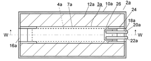
- FIG. 2 is a cross-sectional view of an example of a column module provided in the gas chromatograph apparatus when cut in a vertical direction at a YY position in FIG. 1B.
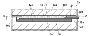
- FIG. 2 is a cross-sectional view when the column module is cut in the horizontal direction at the position XX in FIG. 1A. It is sectional drawing when cut
- the column module may further include a fan for taking cooling air into the gap from the intake port on either the intake port side or the exhaust port side. If it does so, a cooling wind can be efficiently taken in into the clearance gap between a separation column and a heat insulating material, and the cooling efficiency of a separation column can be improved.
- the fan is provided on the inlet side and an air duct is provided between the fan and the inlet. If it does so, external air can be efficiently taken in into the clearance gap between a separation column and a heat insulating material.
- the heater and the separation column are integrally formed in a state of being in contact with each other to form a column temperature adjusting body, between the heat insulating member and the upper surface of the column temperature adjusting body, and between the heat insulating member and the column.
- a gap may be provided between the lower surface of the temperature control unit. If it does so, since the cooling air taken in from the inlet port flows through the upper surface and the lower surface of the column temperature adjusting body, the cooling efficiency of the separation column is further improved.
- a plate-type heater can be cited as a heater for heating the separation column.
- the separation column is fixed in contact with one plane of the plate heater.
- the inside of a column module can be heated with high efficiency.
- a plurality of column modules may be held in the oven. For example, by mounting two or more column modules having separation columns with different separation characteristics in an oven and connecting them in series, components that are not separated by one separation column are separated by another separation column and guided to a detector. Can do.
- the column module 2 is configured such that a column temperature adjusting body 3 is accommodated in a column accommodating member 10.
- the column housing member 10 is a rectangular parallelepiped member, and includes an outer wall and a heat insulating member 12 disposed on the inside thereof.
- the outer wall of the column housing member 10 is formed of metal, for example, stainless steel (SUS304), and the heat insulating member 12 is formed of, for example, glass wool.
- An opening 16 is provided on one end surface of the column housing member 10, and an opening 18 is provided on the other end surface.
- a cavity 14 is provided inside the column housing member 10, and the cavity 14 is surrounded by the heat insulating member 12 at the top and bottom and the sides except for the openings 16 and 18 side.
- the cavity 14 communicates from the opening 16 to the opening 18 so that air can flow through the column housing member 10.
- the column temperature adjusting body 3 is disposed in a cavity 14 surrounded by a heat insulating member 12.
- the column temperature adjusting body 3 is constructed by sandwiching a chip-like separation column 4 made of a flow path substrate on a plate-type heater 6 and sandwiching it from the vertical direction by pressing plates 5 and 7.
- the pressing plate 5 is supported in a state of being separated from the heat insulating member 12 by a base 8 embedded in the heat insulating member 12 below the cavity 14.
- a heater 6, a separation column 4, and a press plate 7 are stacked on the press plate 5 in order from the bottom.
- the base 8 is arranged at positions corresponding to the four corners of the plate-type heater 6, but air enters the separation column 4 through the gap between the pressing plate 5 and the heat insulating member 12 on the lower side. As long as the structure flows along, the base 8 may have any structure.
- the holding plate 7 of the column temperature adjusting body 3 is provided with a through hole 19 that communicates with one end of the separation column 4 and a through hole 23 that communicates with the other end, and an inlet port connected to one end of the separation column 4 through the through hole 19.
- An outlet port 22 connected to the other end of the separation column 4 through 20 and a through hole 23 is installed on the upper surface of the holding plate 7.
- the inlet port 20 is provided for connecting a capillary (pipe) from a sample introduction part for introducing a sample gas
- the outlet port 22 is provided for connecting a capillary leading to a detector for detecting a sample component. Yes.
- the inlet port 20 and the outlet port 22 are drawn out from the outside of the column housing member 10 to the opening 18 in order to enable connection of capillaries.
- the chip-type separation column 4 made of a flow path substrate is used, but a capillary column may be used instead.
- the plate-type heater 6 may be used by being wound around a capillary column using a heating wire.
- a mica heater, a rubber heater, and a ceramic heater can be used as the plate-type heater 6, for example, a mica heater, a rubber heater, and a ceramic heater can be used.
- a column temperature adjusting body 3a composed of a separation column 4a, a heater 6a, and pressing plates 5a and 7a is held on the upper surface by a ceramic arm 24 as a holding member, and is suspended in a cavity 14a in the column housing member 10a. It is supported by the state.
- the ceramic arms 24 are provided so as to extend from the end face side of the column housing member 10a to the cavity 14a side so as to maintain the positions of the four corners of the column temperature adjusting body 3a.
- the cavity 14a is a space in which the upper and lower sides and the sides are surrounded by the heat insulating member 12a except for the openings 16a and 18a. Openings 16a and 18a are provided at both end faces of the column housing member 10a so that outside air can flow through the cavity 14a.
- the pressing plate 7a has a notch 26 on one end side, and the inlet port 20a and the outlet port 22a of the separation column 4 are provided in the notch 26.
- the insulation between the upper surface of the column temperature adjusting body 3 a and the heat insulating member 12 a on the upper side and the lower surface of the column temperature adjusting body 3 a and the lower heat insulation on the lower side There is a gap serving as an air passage between the member 12a and the outside air taken into the column housing member 10a from one of the openings 16a and 18a is transferred between the column temperature adjusting body 3a and the heat insulating member 12a. It is possible to exhaust air from the other opening through the gap. Thereby, the column temperature adjusting body 4a can be cooled with high efficiency.
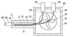
- FIG. 3 schematically shows the structure of the column module 2.
- the sample introduction part 38 and the detector 40 are attached to the upper surface of the casing 32 of the oven 30.
- Capillaries 42 and 44 are accommodated in the internal space 34 of the housing 32.
- the capillary 42 connects between the sample introduction unit 38 and the column module 2
- the capillary 44 connects between the column module 2 and the detector 40.
- the column module 2 is attached to the side wall of the casing 32 of the oven 30.
- the column module 2 is fixed to the casing 32 of the oven 30 in a state where the separation column 4 is horizontal so that the end face provided with the opening 18 is on the oven 30 side.
- An opening is provided in the side wall of the housing 32 to which the column module 2 is mounted, and one ends of the capillaries 42 and 44 are connected to the ports 20 and 22 of the column module 2 through the opening.
- the oven 30 has a heater (not shown) and a fan 36 in the internal space 34 of the heat-insulating housing 32, and controls the temperature of the internal space 34.
- the column module 2 controls the temperature of the separation column 4 independently of the oven 30. Since the column housing member 10 of the column module 2 has a structure in which the internal cavity 14 is surrounded by the heat insulating material 12, the temperature of the separation column 4 is controlled without being affected by temperature fluctuations or convection outside the column housing member 10. Can do. Since the heat capacity is smaller than that of the oven 30, rapid temperature increase and cooling are possible.
- the cooling in the separation column 4 and the oven 30 is performed by exhausting the air in the internal space 34 of the oven 30 by the fan 36 to reduce the pressure, and taking the external air into the internal space 34.
- the outside air is taken into the internal space 34 through the column module 2. That is, when the internal space 34 of the oven 30 is depressurized by the fan 36, the outside air is taken in from the opening 16 of the column module 2, passes through the cavity 14 in the column module 2, and is taken into the internal space 34 from the opening 18. It is. Accordingly, since the outside air passes through the column module 2 having a small heat capacity along the separation column 4, the separation column 4 can be rapidly cooled.
- the opening 16 of the column module 2 constitutes an intake port for taking outside air into the cavity 14, and the opening 18 constitutes an exhaust port for exhausting outside air from the cavity 14.
- a column fan 48 may be provided on the opening 16 side of the column module 2 via an air duct 46.
- the outside air is sent to the column module 2 side by the column fan 48, whereby the amount of cooling air flowing along the separation column 4 is increased, and the separation column 4 can be quickly cooled.
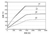
- the column module 2 is mounted in the oven 30 in a state where the separation column 4 is horizontal (hereinafter referred to as “horizontal placement”), so that the temperature distribution in the column module 2 is achieved. And the temperature of the separation column 4 can be uniformly controlled in its main plane.
- the column module 2 is arranged so that the separation column 4 is arranged vertically (hereinafter referred to as “vertically placed”), a temperature distribution in the vertical direction is generated in the column module 2 by the convection of heat, and the separation column 4 It becomes difficult to control the temperature uniformly.
- FIG. 6 shows the time change of each measured temperature when the column module 2 is placed vertically
- FIG. 7 shows the time change of each measured temperature when the column module 2 is placed horizontally.
- the temperature is measured at a position a1 of 20 mm from one end side of the separation column 4, a position a2 in the air layer in the vicinity thereof, a position b1 of 20 mm from the other end side of the separation column 4, and A thermocouple was inserted into position b2 in the air layer in the vicinity thereof.
- the interval between a1 and a2 is 60 mm.
- the gas chromatograph may include the column module 2a shown in FIGS. 2A and 2B. Good.
- one column module 2 is mounted on the oven 30, but the present invention is not limited to this, and two or more column modules 2 may be mounted on the oven 30.
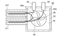
- FIG. 8 shows an embodiment of a gas chromatograph apparatus in which a plurality of column modules are held in an oven.
- Two column modules 2-1 and 2-2 are mounted in the oven 30 in parallel with each other so that the respective separation columns 4 are horizontal.
- the column modules 2-1 and 2-2 are connected in series.
- the sample introduction part 38 is connected to the inlet port of the column module 2-1 through the capillary 42a.
- the outlet port of the column module 2-1 and the inlet port of the column module 2-2 are connected via a capillary 43.
- the outlet port of the column module 2-2 is connected to the detector 40 via the capillary 44a.
- the column modules 2-1 and 2-2 of this embodiment may be the column module 2 in FIG. 1 or the column module 2a in FIG.
Landscapes
- Physics & Mathematics (AREA)
- Health & Medical Sciences (AREA)
- Life Sciences & Earth Sciences (AREA)
- Chemical & Material Sciences (AREA)
- Analytical Chemistry (AREA)
- Biochemistry (AREA)
- General Health & Medical Sciences (AREA)
- General Physics & Mathematics (AREA)
- Immunology (AREA)
- Pathology (AREA)
- Sampling And Sample Adjustment (AREA)
Abstract
Description
そして、本発明のガスクロマトグラフ装置のカラムモジュールは、分離カラムが断熱部材で囲われてカラム収容部材内に収容されているので、分離カラムが外気と遮断され、外気の対流や温度変化の影響によって分離カラムの温度が変動することを抑制できる。これにより、分析結果の再現性が向上する。さらに、分離カラムと断熱部材との間に分離カラムに沿って空気を流すための隙間が設けられ、さらにその隙間に外気を取り込むための吸気口及び隙間の空気を排気するための排気口がカラム収容部に設けられているので、分離カラムの冷却時にカラムモジュール内に外気を取り込んでカラム収容部材と分離カラムとの間の隙間に流すことができ、分離カラムの冷却効率を向上させることができる。これにより、分離カラムの温度を上昇させる際は断熱部材による外気との遮断効果によって迅速な分離カラムの昇温が可能であり、分離カラムを冷却する際は分離カラムに沿った外気の流通効果によって迅速な分離カラムの冷却が可能であるため、分離カラムの温度調整による待機時間が短縮され、分析動作の処理効率が向上する。
まず、図1A及び図1Bを用いて、ガスクロマトグラフ装置の備えているカラムモジュールについて説明する。
カラムモジュール2はカラム温調体3がカラム収容部材10内に収容されて構成されている。カラム収容部材10は直方体形状の部材であり、外壁とその内側に配置された断熱部材12とで構成されている。カラム収容部材10の外壁は金属、例えばステンレス(SUS304)で形成され、断熱部材12は例えばグラスウールで形成されている。カラム収容部材10の一方の端面に開口部16が設けられ、他方の端面に開口部18が設けられている。カラム収容部材10の内部には空洞14が設けられ、その空洞14は開口部16,18側を除いて、上下と側方が断熱部材12によって囲われている。空洞14は開口部16から開口部18まで通じており、空気がカラム収容部材10内を流通することができるようになっている。
プレート型のヒータ6としては、例えばマイカヒータ、ラバーヒータ及びセラミックヒータを使用することができる。
このカラムモジュール2aは分離カラム4a、ヒータ6a、押さえ板5a及び7aからなるカラム温調体3aが、保持部材であるセラミックアーム24によって上面が保持され、カラム収容部材10a内の空洞14a内において宙づりの状態に支持されている。セラミックアーム24はカラム温調体3aの四隅の位置を保持するように、カラム収容部材10aの端面側から空洞14a側へ延びるように設けられている。
4 分離カラム
5,5a,7,7a 押さえ板
6,6a ヒータ
8,8a 支持部材
10,10a カラム収容部材
12,12a 断熱部材
14,14a 隙間
16,16a 吸気口
18,18a 排気口
20,20a カラム入口ポート
22,22a カラム出口ポート
24 セラミックアーム
26 切欠き部
30 オーブン
32 オーブン筐体
34 オーブン内空間
36 オーブンファン
38 試料導入部
40 検出器
42,44 キャピラリ
46 エアダクト
48 カラム冷却ファン
Claims (6)
- 試料ガスを成分ごとに分離する分離カラム、前記分離カラムの周囲を断熱部材で囲って内部に収容するとともに、前記分離カラムと前記断熱部材との間に前記分離カラムに沿って空気を流すための隙間を有するカラム収容部材、前記カラム収容部材内に設けられ前記分離カラムに直接的又は間接的に接触して前記分離カラムを加熱するヒータ、前記カラム収容部材に設けられ前記隙間に外気を取り込むための吸気口及び前記カラム収容部材の前記吸気口とは別の位置に設けられ前記隙間の空気を排気するための排気口を備えたカラムモジュールと、
前記カラムモジュールの分離カラムに試料ガスを導入するための試料導入部と、
前記分離カラムで分離された試料成分を検出するための検出器と、
前記試料導入部と前記分離カラムとの間及び前記検出器と前記分離カラムとの間をそれぞれ接続するための流路を収容し、その内部温度を一定温度に調節するオーブンと、を備え、
前記カラムモジュールは前記分離カラムが水平に配置された状態で前記オーブンに保持されているガスクロマトグラフ装置。 - 前記カラムモジュールは、前記吸気口側又は前記排気口側のいずれか一方に前記吸気口から前記隙間に冷却風を取り込むためのファンをさらに備えている請求項1に記載のガスクロマトグラフ装置。
- 前記ファンは前記吸気口側に設けられ、前記ファンと前記吸気口の間にエアダクトが設けられている請求項2に記載のガスクロマトグラフ装置。
- 前記ヒータと前記分離カラムは互いに接触した状態で一体として構成されてカラム温調体をなし、
前記断熱部材と前記カラム温調体の上面との間及び前記断熱部材と前記カラム温調部の下面との間にそれぞれ隙間が設けられている請求項1から3のいずれか一項に記載のガスクロマトグラフ装置。 - 前記ヒータはプレート型ヒータであり、前記分離カラムは前記プレート型ヒータの一平面に接触した状態で固定されている請求項1から4のいずれか一項に記載のガスクロマトグラフ装置。
- 前記オーブンに複数の前記カラムモジュールが保持されている請求項1から5のいずれか一項に記載のガスクロマトグラフ装置。
Priority Applications (4)
| Application Number | Priority Date | Filing Date | Title |
|---|---|---|---|
| US14/437,863 US10241092B2 (en) | 2012-10-25 | 2012-10-25 | Gas chromatograph device |
| PCT/JP2012/077616 WO2014064804A1 (ja) | 2012-10-25 | 2012-10-25 | ガスクロマトグラフ装置 |
| CN201280076451.2A CN104737012A (zh) | 2012-10-25 | 2012-10-25 | 气相色谱仪装置 |
| JP2014543079A JP5949934B2 (ja) | 2012-10-25 | 2012-10-25 | ガスクロマトグラフ装置 |
Applications Claiming Priority (1)
| Application Number | Priority Date | Filing Date | Title |
|---|---|---|---|
| PCT/JP2012/077616 WO2014064804A1 (ja) | 2012-10-25 | 2012-10-25 | ガスクロマトグラフ装置 |
Publications (1)
| Publication Number | Publication Date |
|---|---|
| WO2014064804A1 true WO2014064804A1 (ja) | 2014-05-01 |
Family
ID=50544202
Family Applications (1)
| Application Number | Title | Priority Date | Filing Date |
|---|---|---|---|
| PCT/JP2012/077616 Ceased WO2014064804A1 (ja) | 2012-10-25 | 2012-10-25 | ガスクロマトグラフ装置 |
Country Status (4)
| Country | Link |
|---|---|
| US (1) | US10241092B2 (ja) |
| JP (1) | JP5949934B2 (ja) |
| CN (1) | CN104737012A (ja) |
| WO (1) | WO2014064804A1 (ja) |
Cited By (5)
| Publication number | Priority date | Publication date | Assignee | Title |
|---|---|---|---|---|
| JP2015225017A (ja) * | 2014-05-29 | 2015-12-14 | 横河電機株式会社 | ガスクロマトグラフ |
| JP2018155568A (ja) * | 2017-03-17 | 2018-10-04 | 株式会社島津製作所 | ガスクロマトグラフ |
| CN110785659A (zh) * | 2017-09-21 | 2020-02-11 | 株式会社岛津制作所 | 柱温箱 |
| JP2020024209A (ja) * | 2014-09-13 | 2020-02-13 | アジレント・テクノロジーズ・インクAgilent Technologies, Inc. | 装置 |
| US11940423B2 (en) | 2020-03-25 | 2024-03-26 | Shimadzu Corporation | Gas chromatograph |
Families Citing this family (4)
| Publication number | Priority date | Publication date | Assignee | Title |
|---|---|---|---|---|
| CN105572272A (zh) * | 2016-01-15 | 2016-05-11 | 湖南师范大学 | 一种新结构的毛细管加热装置 |
| US12050210B2 (en) * | 2019-02-27 | 2024-07-30 | Hitachi High-Tech Corporation | Analysis apparatus column oven |
| US12078618B2 (en) * | 2019-06-10 | 2024-09-03 | Shimadzu Corporation | Gas chromatograph-mass spectrometer |
| WO2021166255A1 (ja) * | 2020-02-21 | 2021-08-26 | 株式会社島津製作所 | 液体クロマトグラフおよび分析方法 |
Citations (3)
| Publication number | Priority date | Publication date | Assignee | Title |
|---|---|---|---|---|
| JPS5977063U (ja) * | 1982-11-16 | 1984-05-24 | 株式会社島津製作所 | 高速液体クロマトグラフ用カラムオ−ブン |
| JPH08327620A (ja) * | 1995-05-31 | 1996-12-13 | Hewlett Packard Co <Hp> | 分析機器並びに該機器における熱絶縁機器と熱絶縁方法 |
| US6530260B1 (en) * | 2002-02-04 | 2003-03-11 | Rvm Scientific, Inc. | Gas chromatography analysis system |
Family Cites Families (14)
| Publication number | Priority date | Publication date | Assignee | Title |
|---|---|---|---|---|
| FI117179B (fi) * | 2004-01-23 | 2006-07-14 | Environics Oy | Kaasukromatografi |
| US6920777B1 (en) * | 2004-02-02 | 2005-07-26 | Agilent Technologies, Inc. | Intake cross-sheets for gas chromatographic oven |
| US7291203B2 (en) * | 2004-03-10 | 2007-11-06 | Petroleum Ana Ryzes Company Lp | Negative temperature profiling using microwave GC apparatus |
| CN201273894Y (zh) | 2004-05-04 | 2009-07-15 | 珀金埃尔默Las公司 | 带有热交换装置的气相色谱分析炉 |
| US20060008385A1 (en) * | 2004-07-08 | 2006-01-12 | Millor Sammye E Ii | Method and apparatus for an analytical instrument oven module with variable speed fan |
| CN100432669C (zh) * | 2005-06-06 | 2008-11-12 | 张西咸 | 一种高精度温度控制微型色谱柱箱 |
| US8642931B2 (en) * | 2006-03-13 | 2014-02-04 | Valco Instruments Company, L.P. | Adaptive temperature controller |
| JP5040990B2 (ja) * | 2007-02-23 | 2012-10-03 | 東ソー株式会社 | カラムオーブン二重温調 |
| CN101382526A (zh) * | 2007-09-05 | 2009-03-11 | 中国科学院大连化学物理研究所 | 一种直热式快速程序升温气相色谱柱 |
| US20090173146A1 (en) * | 2008-01-07 | 2009-07-09 | Matthias Pursch | Temperature programmed low thermal mass fast liquid chromatography analysis system |
| CN201247230Y (zh) * | 2008-05-09 | 2009-05-27 | 中国石油天然气股份有限公司 | 管式色谱柱加热装置 |
| US8591630B2 (en) * | 2010-10-06 | 2013-11-26 | Aviv Amirav | Fast gas chromatograph method and device for analyzing a sample |
| CN102095824B (zh) * | 2011-01-30 | 2013-06-12 | 上海仪电分析仪器有限公司 | 一种毛细管色谱柱柱上加热装置 |
| US20130139574A1 (en) * | 2011-06-03 | 2013-06-06 | Phoenix S&T, Inc. | Devices for heating and cooling a capillary liquid chromatographic system |
-
2012
- 2012-10-25 US US14/437,863 patent/US10241092B2/en active Active
- 2012-10-25 CN CN201280076451.2A patent/CN104737012A/zh active Pending
- 2012-10-25 JP JP2014543079A patent/JP5949934B2/ja active Active
- 2012-10-25 WO PCT/JP2012/077616 patent/WO2014064804A1/ja not_active Ceased
Patent Citations (3)
| Publication number | Priority date | Publication date | Assignee | Title |
|---|---|---|---|---|
| JPS5977063U (ja) * | 1982-11-16 | 1984-05-24 | 株式会社島津製作所 | 高速液体クロマトグラフ用カラムオ−ブン |
| JPH08327620A (ja) * | 1995-05-31 | 1996-12-13 | Hewlett Packard Co <Hp> | 分析機器並びに該機器における熱絶縁機器と熱絶縁方法 |
| US6530260B1 (en) * | 2002-02-04 | 2003-03-11 | Rvm Scientific, Inc. | Gas chromatography analysis system |
Cited By (6)
| Publication number | Priority date | Publication date | Assignee | Title |
|---|---|---|---|---|
| JP2015225017A (ja) * | 2014-05-29 | 2015-12-14 | 横河電機株式会社 | ガスクロマトグラフ |
| JP2020024209A (ja) * | 2014-09-13 | 2020-02-13 | アジレント・テクノロジーズ・インクAgilent Technologies, Inc. | 装置 |
| JP2018155568A (ja) * | 2017-03-17 | 2018-10-04 | 株式会社島津製作所 | ガスクロマトグラフ |
| CN110785659A (zh) * | 2017-09-21 | 2020-02-11 | 株式会社岛津制作所 | 柱温箱 |
| CN110785659B (zh) * | 2017-09-21 | 2022-11-25 | 株式会社岛津制作所 | 柱温箱 |
| US11940423B2 (en) | 2020-03-25 | 2024-03-26 | Shimadzu Corporation | Gas chromatograph |
Also Published As
| Publication number | Publication date |
|---|---|
| JPWO2014064804A1 (ja) | 2016-09-05 |
| US20150268201A1 (en) | 2015-09-24 |
| US10241092B2 (en) | 2019-03-26 |
| JP5949934B2 (ja) | 2016-07-13 |
| CN104737012A (zh) | 2015-06-24 |
Similar Documents
| Publication | Publication Date | Title |
|---|---|---|
| JP5949934B2 (ja) | ガスクロマトグラフ装置 | |
| CN104101670B (zh) | 色谱柱单元以及具有该色谱柱单元的气相色谱仪装置 | |
| JP5943085B2 (ja) | ガスクロマトグラフ装置 | |
| US11402278B2 (en) | Low-temperature dry block temperature calibrator | |
| WO2024000284A1 (zh) | 温度补偿系统、半导体设备和温度补偿方法 | |
| US8721173B2 (en) | Temperature calibration device, a calibrator block, and a method for calibrating a temperature probe | |
| US9689847B2 (en) | Gas chromatography equipment | |
| TW200411960A (en) | Variable heater element for low to high temperature ranges | |
| CN103424495A (zh) | 用于气相色谱仪的色谱柱加热装置 | |
| KR102079533B1 (ko) | 유량 제어 밸브 및 그것을 사용한 질량 유량 제어 장치 | |
| WO2019137343A1 (zh) | 导流散热型干体温度校验仪 | |
| KR101422915B1 (ko) | 온도 제어 유닛, 기판 탑재대, 기판 처리 장치, 온도 제어 시스템 및 기판 처리 방법 | |
| US10067101B2 (en) | Gas chromatography (GC) column heater | |
| TW202401195A (zh) | 溫度補償系統、半導體設備和溫度補償方法 | |
| CN105911203A (zh) | 气相色谱仪装置和柱组件 | |
| CN101813652A (zh) | 示差扫描热量计 | |
| JP7846463B2 (ja) | ガスクロマトグラフ | |
| JP5469913B2 (ja) | 断熱構造及びこの断熱構造を有する収納装置 | |
| SU813246A1 (ru) | Термостат дл хроматографа | |
| JP5551811B2 (ja) | 示差走査熱量計 | |
| CN120631089A (zh) | 芯片独立控温系统及方法 | |
| CN121334907A (zh) | 加热装置及加工设备 | |
| JP2007335937A (ja) | 原子発振器及び原子発振器の温度制御方法 |
Legal Events
| Date | Code | Title | Description |
|---|---|---|---|
| 121 | Ep: the epo has been informed by wipo that ep was designated in this application |
Ref document number: 12886928 Country of ref document: EP Kind code of ref document: A1 |
|
| ENP | Entry into the national phase |
Ref document number: 2014543079 Country of ref document: JP Kind code of ref document: A |
|
| WWE | Wipo information: entry into national phase |
Ref document number: 14437863 Country of ref document: US |
|
| NENP | Non-entry into the national phase |
Ref country code: DE |
|
| 122 | Ep: pct application non-entry in european phase |
Ref document number: 12886928 Country of ref document: EP Kind code of ref document: A1 |