WO2014061543A1 - ベローズシール - Google Patents
ベローズシール Download PDFInfo
- Publication number
- WO2014061543A1 WO2014061543A1 PCT/JP2013/077578 JP2013077578W WO2014061543A1 WO 2014061543 A1 WO2014061543 A1 WO 2014061543A1 JP 2013077578 W JP2013077578 W JP 2013077578W WO 2014061543 A1 WO2014061543 A1 WO 2014061543A1
- Authority
- WO
- WIPO (PCT)
- Prior art keywords
- seal
- bellows
- ring
- retainer
- sealing ring
- Prior art date
Links
Images


Classifications
-
- F—MECHANICAL ENGINEERING; LIGHTING; HEATING; WEAPONS; BLASTING
- F16—ENGINEERING ELEMENTS AND UNITS; GENERAL MEASURES FOR PRODUCING AND MAINTAINING EFFECTIVE FUNCTIONING OF MACHINES OR INSTALLATIONS; THERMAL INSULATION IN GENERAL
- F16J—PISTONS; CYLINDERS; SEALINGS
- F16J15/00—Sealings
- F16J15/16—Sealings between relatively-moving surfaces
- F16J15/34—Sealings between relatively-moving surfaces with slip-ring pressed against a more or less radial face on one member
- F16J15/3404—Sealings between relatively-moving surfaces with slip-ring pressed against a more or less radial face on one member and characterised by parts or details relating to lubrication, cooling or venting of the seal
- F16J15/3408—Sealings between relatively-moving surfaces with slip-ring pressed against a more or less radial face on one member and characterised by parts or details relating to lubrication, cooling or venting of the seal at least one ring having an uneven slipping surface
- F16J15/3412—Sealings between relatively-moving surfaces with slip-ring pressed against a more or less radial face on one member and characterised by parts or details relating to lubrication, cooling or venting of the seal at least one ring having an uneven slipping surface with cavities
-
- F—MECHANICAL ENGINEERING; LIGHTING; HEATING; WEAPONS; BLASTING
- F16—ENGINEERING ELEMENTS AND UNITS; GENERAL MEASURES FOR PRODUCING AND MAINTAINING EFFECTIVE FUNCTIONING OF MACHINES OR INSTALLATIONS; THERMAL INSULATION IN GENERAL
- F16J—PISTONS; CYLINDERS; SEALINGS
- F16J15/00—Sealings
- F16J15/16—Sealings between relatively-moving surfaces
- F16J15/34—Sealings between relatively-moving surfaces with slip-ring pressed against a more or less radial face on one member
- F16J15/3436—Pressing means
- F16J15/3452—Pressing means the pressing force resulting from the action of a spring
-
- F—MECHANICAL ENGINEERING; LIGHTING; HEATING; WEAPONS; BLASTING
- F16—ENGINEERING ELEMENTS AND UNITS; GENERAL MEASURES FOR PRODUCING AND MAINTAINING EFFECTIVE FUNCTIONING OF MACHINES OR INSTALLATIONS; THERMAL INSULATION IN GENERAL
- F16J—PISTONS; CYLINDERS; SEALINGS
- F16J15/00—Sealings
- F16J15/16—Sealings between relatively-moving surfaces
- F16J15/34—Sealings between relatively-moving surfaces with slip-ring pressed against a more or less radial face on one member
- F16J15/36—Sealings between relatively-moving surfaces with slip-ring pressed against a more or less radial face on one member connected by a diaphragm or bellow to the other member
- F16J15/363—Sealings between relatively-moving surfaces with slip-ring pressed against a more or less radial face on one member connected by a diaphragm or bellow to the other member the diaphragm or bellow being made of metal
Definitions
- the present invention relates to a bellows used for sealing high-temperature and high-pressure liquids exceeding 200 ° C. in petroleum refining, petrochemicals, ironmaking chemistry, etc., for example, high-pressure pumps and compressors for handling hot oil in vacuum distillation equipment of oil refining plants. Regarding the seal.
- FIG. 3 a device having an inner periphery through which a rotating shaft 51 is inserted.
- a seal cover 52 attached to the outer surface in the axial direction of the rotation shaft 51 in the main body 50, a first seal ring 53 disposed on the inner peripheral side of the seal cover 52 so as to be movable in the axial direction, and a second fixed to the rotation shaft 51.
- a seal ring 54 and a spring 55 disposed on the inner peripheral side of the seal cover 52 and pressing the first seal ring 53 in the direction of the second seal ring 54 are attached to the inner peripheral side of the seal cover 52.
- the mechanical seal of the prior art 1 can secure the pressing force against the first sealing ring by the spring pressing force by attaching the spring to the seal cover, and the bellows is disposed in the mechanical seal device in the vicinity of the free length. Therefore, the axial dimension can be made smaller than that of the conventional bellows.
- the first sealing ring is fixed to the retainer by shrink fitting, the first sealing ring
- the compressive stress due to shrink fitting is always acting, and there is a concern about the breakage of the first sealing ring.
- the mechanical seal of the prior art 2 solves the problem of shrink fitting of the first seal ring to the retainer of the prior art 1, but the case where the first seal ring and the retainer have a lap joint structure. Since measures against the sealed fluid pressure of the first sealing ring are not taken, the sealing performance of the sealing surface of the first sealing ring and the second sealing ring and the sealing performance of the lap surface of the first sealing ring and the retainer are insufficient. There was a problem of being.
- the present invention relates to a bellows used for sealing high-temperature and high-pressure liquids exceeding 200 ° C. in petroleum refining, petrochemicals, ironmaking chemistry, etc., for example, high-pressure pumps and compressors for handling hot oil in vacuum distillation equipment of oil refining plants.
- the seal prevents damage due to shrink fitting of the sealing ring on the fixed side that is axially movable via the bellows on the inner peripheral side of the seal cover, prevents damage due to the stress of the bellows, and improves sealing performance at the same time.
- the object is to provide a bellows seal that can be established.
- a bellows seal of the present invention includes a seal cover formed between a housing and a rotating shaft and attached to a shaft seal portion, and is axially movable toward the inner peripheral side of the seal cover.
- a first seal ring disposed on the rotary shaft, a second seal ring fixed to the rotating shaft, and attached to an inner peripheral side of the seal cover, and extending and contracting in an axial direction between the seal cover and the first seal ring
- the first seal ring is hermetically connected to an end surface of a retainer fixed to the bellows by a lap joint, and the first seal ring and the retainer are prevented from rotating toward the seal cover by a knock pin.
- the bellows since the spring has a sufficient pressing force with respect to the first sealing ring, the bellows does not need to have a pressing force with respect to the first sealing ring, and the bellows is in a state near the free length. Can be mounted, the internal stress due to the compression of the bellows can be minimized, the number of bellows ridges can be reduced, the production cost of bellows can be reduced, and the bellows seal can be made compact Can do. Also, since the knock pin takes over the torque associated with the sliding of the first sealing ring and does not act on the bellows, the bellows is not affected even if the sliding torque fluctuates.
- the first sealing ring Since only the minimum internal stress due to the above acts, the combined stress can be minimized and the breakdown voltage can be improved.
- the first sealing ring has a structure in which the retainer and the lap joint are hermetically connected, the compressive stress due to shrink fitting does not act on the first sealing ring as in the prior art 1. Can prevent damage.
- the first sealing ring since the first sealing ring has a single structure, the change in flatness due to heat can be minimized.
- the bellows seal according to the present invention is secondly characterized in that, in the first feature, the first sealing ring includes a stepped portion projecting toward the retainer side, and an inner diameter of the stepped portion projecting toward the retainer side is equal to that of the bellows. It is characterized by being set to be larger than the center diameter. According to this feature, a pressing force due to pressure is applied to the contact portion on the inner peripheral side of the stepped portion protruding to the retainer side via the bellows, so that the sealing performance between the first sealing ring and the retainer is sufficiently maintained. be able to.
- the bellows seal of the present invention is characterized in that, in the first or second feature, the first seal ring has an centroid in an axial cross section between an intermediate position between the second seal ring and the retainer. It is set to be located on the opposite side to the second sealing ring. According to this feature, the first sealing ring is in sliding contact with the second sealing ring at the outer peripheral height, and the sealing performance of the sliding surfaces of the first sealing ring and the second sealing ring can be improved.
- the first sealing ring has a main body portion formed in a shape that is substantially symmetrical with respect to the centroid.
- the height of the step protruding to the second sealing ring side is set larger than the height of the step protruding to the retainer side.
- the radial width of the step portion projecting toward the retainer side of the first seal ring is a step portion projecting toward the second seal ring side. It is characterized by being set smaller than the width in the radial direction. According to this feature, the contact pressure between the retainer and the stepped portion that protrudes toward the retainer is greater than the contact pressure between the first seal ring and the second seal ring, so the sealing performance between the first seal ring and the retainer is improved. can do.
- the present invention has the following excellent effects. (1) Since the spring has a sufficient pressing force with respect to the first sealing ring, the bellows does not need to have a pressing force with respect to the first sealing ring, and the bellows can be attached in the vicinity of the free length. In addition, the internal stress due to the compression of the bellows can be minimized, the number of bellows ridges can be reduced, the production cost of the bellows can be reduced, and the bellows seal can be made compact. Also, since the knock pin takes over the torque associated with the sliding of the first sealing ring and does not act on the bellows, the bellows is not affected even if the sliding torque fluctuates.
- the first sealing ring Since only the minimum internal stress due to the above acts, the combined stress can be minimized and the breakdown voltage can be improved.
- the first sealing ring has a structure in which the retainer and the lap joint are hermetically connected, the compressive stress due to shrink fitting does not act on the first sealing ring as in the prior art 1. Can prevent damage.
- the first sealing ring since the first sealing ring has a single structure, the change in flatness due to heat can be minimized.
- the first sealing ring includes a stepped portion that protrudes toward the retainer side, and the inner diameter of the stepped portion that protrudes toward the retainer side is set to be equal to or greater than the center diameter of the bellows, thereby protruding toward the retainer side via the bellows. Since a pressing force due to pressure is applied to the contact portion on the inner peripheral side of the stepped portion, the sealing performance between the first sealing ring and the retainer can be sufficiently maintained.
- a stepped portion projecting toward the retainer side by setting a radial width of the stepped portion projecting toward the retainer side of the first seal ring smaller than a radial width of the stepped portion projecting toward the moving surface side; Since the surface pressure with the retainer becomes larger than the surface pressure between the first sealing ring and the second sealing ring, the sealing performance between the first sealing ring and the retainer can be improved.
- FIG. 3 is a view as seen from an arrow A in FIG. 2. It is a longitudinal cross-sectional view explaining the whole bellows seal of prior art 1.
- FIG. 1 A bellows seal according to Embodiment 1 of the present invention will be described with reference to FIGS. 1 and 2.
- reference numeral 1 indicates a high-pressure / high-temperature liquid exceeding 200 ° C. in petroleum refining, petrochemical and iron chemistry, for example, a handling 2 for a pump or the like that handles hot oil in a vacuum distillation facility of an oil refining plant.
- the right side is the machine inside (high pressure fluid side)
- the left side is the machine outside (atmosphere side).
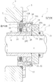
- the bellows seal 1 has a seal cover 3 attached to the housing 2 at a shaft sealing portion formed between the housing 2 and the rotary shaft 4, and a sleeve collar 5 and a sleeve 6 fitted to the rotary shaft 4.
- the seal cover 3 is hermetically attached to the housing 2 via an O-ring 7 by fixing means such as a bolt (not shown).
- the seal ring 8 constituting the first seal ring, the mating ring 9 constituting the second seal ring, the adapter 10, the bellows 11, the retainer 12, and the spring 13 are disposed on the inner peripheral side of the seal cover 3.
- the bellows 11 is attached between the adapter 10 and the retainer 12 so as to be stretchable along the axial direction of the rotary shaft 4.
- the metal which comprises the bellows 11 is manufactured from either materials, such as alloys, such as stainless steel, Inconel, Hastelloy, and a carpenter, and titanium.
- the bellows 11, the adapter 10, and the retainer 12 are fixed by, for example, welding.
- a plurality of springs 13 are arranged in the circumferential direction on the inner periphery of the seal cover 3 on the outer side in the radial direction of the bellows 11.
- the number of springs 13 is not particularly limited, but is 4 to 24.
- the mating ring 9 has one end abutting against the end surface of the sleeve 6 via the O-ring 14 and the other end abutting against the sleeve collar 5 via the O-ring 15, and is sandwiched between the sleeve 6 and the sleeve collar 5. It is attached and fixed to the rotating shaft 4 and rotates as the rotating shaft 4 rotates.
- a sliding surface 9S is formed on a side surface of the mating ring 9 facing the seal ring 8 side, and is in close contact with the sliding surface 8S of the seal ring 8 to rotate and slide.
- the mating ring 9 is manufactured from any material such as SiC (silicon carbide) or WC (tungsten carbide), carbon, and other ceramics, which are super-hard materials.
- a protrusion 3A that protrudes inward in the radial direction is formed on the inner periphery of the seal cover 3.
- An adapter 10 that holds one end of the bellows 11 is fitted to the inner peripheral surface of the protrusion 3A and the inner side surface of the protrusion 3A, and is fixed by welding.
- a cylindrical portion 3 ⁇ / b> B that extends toward the inner side of the axial machine and covers the outer peripheral surface of the seal ring 8 is formed on the inner periphery of the seal cover 3.
- a retainer 12 is fixed to the other end of the bellows 11.
- the retainer 12 is formed with a protrusion 12A extending outward in the radial direction, and the protrusion 12A and the seal ring 8 are prevented from rotating on the inner surface of the seal cover 3 by a knock pin 17.
- a spring 13 is disposed between the protruding portion 12A and the inner surface of the seal cover 3, and the protruding portion 12A is directed toward the mating ring 9 along the axial direction of the rotating shaft 4 by the spring 13.
- the seal ring 8 is pressed and pressed toward the mating ring 9 along the axial direction of the rotary shaft 4 via the protrusion 12A. Thereby, the sliding surface 8S of the seal ring 8 slides in close contact with the sliding surface 9S of the facing mating ring 9.
- the seal ring 8 has a main body portion 8A formed in a substantially symmetrical shape with respect to the centroid, and includes a step portion 8B protruding from the main body portion 8A toward the mating ring 9 and a step portion 8C protruding toward the retainer 12 side.
- the tip of the stepped portion 8B forms a sliding surface 8S and slides in close contact with the sliding surface 9S of the facing mating ring 9. Further, the tip end of the stepped portion 8 ⁇ / b> C contacts the retainer 12.
- the end of the stepped portion 8C and the end surface of the retainer 12 that contacts the tip of the stepped portion 8C are lapped, and both the lapped surfaces are hermetically connected with a lap joint.
- the seal ring 8 is manufactured from any material such as SiC (silicon carbide) or WC (tungsten carbide), carbon, and other ceramics, which are super-hard materials.
- the gap between the outer periphery of the seal ring 8 and the inner periphery of the cylindrical portion 3B that covers the outer peripheral surface of the seal ring 8 of the seal cover 3 is set to be a minimum gap, and the value shifted in the radial direction of the seal ring 8 is set. It is small.
- a snap ring 18 is attached to the inner peripheral surface on the distal end side of the cylindrical portion 3B.
- the centroid in the axial section of the seal ring 8 is located on the retainer 12 side, that is, on the opposite side of the mating ring 9 from the middle between the mating ring 9 and the retainer 12.
- L the distance from the mating ring 9 side to the centroid
- b the distance between the mating ring 9 and the retainer 12
- L> b / 2 is set.
- Such a shift of the centroid toward the anti-mate ring 9 side is, in this example, the retainer 12 in the step portion 8B protruding from the substantially symmetrical main body portion 8A of the seal ring 8 toward the mating ring 9 side.
- the protruding height is set larger than the stepped portion 8C protruding to the side. Since the cross-sectional areas of the step 8B and the step 8C are sufficiently smaller than the main body 8A, the centroid of the main body 8A is mated by setting the height of the step 8B to be higher than the height of the step 8C. As a result, the entire centroid in the axial cross section of the seal ring 8 is shifted to the side opposite to the mating ring 9 from the middle between the mating ring 9 and the retainer 12. .
- the inner diameter D Li of the step portion 8 ⁇ / b> C protruding to the retainer 12 side of the seal ring 8 is set to be equal to or larger than the center diameter D m of the bellows 11. Further, the radial width W 2 of the step portion 8C projecting retainer 12 side of the seal ring 8 is set smaller than the width W 1 in the radial direction of the step portion 8B projecting mating ring 9 side.
- the spring 13 is attached to the inner peripheral side of the seal cover 3 along the axial direction of the rotating shaft 4 in which the bellows 11 expands and contracts. Since the spring 13 has a sufficient pressing force against the seal ring 8 via the retainer 12, the bellows 11 does not need to have a pressing force against the seal ring 8. Therefore, the bellows 11 can be attached in the vicinity of the free length, and the internal stress due to the compression of the bellows 11 can be minimized. That is, since the number of peaks of the bellows 11 can be reduced, the production cost of the bellows 11 can be reduced. Moreover, the bellows seal 1 can be made compact. The number of peaks of the bellows 11 is desirably 6 or less, and preferably 4.
- the seal ring 8 since the seal ring 8 has a structure in which the retainer 12 and the lap joint are hermetically connected, the compressive stress due to shrink fitting does not act on the seal ring 8 as in the related art 1, so that the compressive stress is applied. Breakage can be prevented. Furthermore, since the seal ring 8 has a single structure, changes in flatness due to heat can be minimized.
- the retainer 12 and the seal ring 8 are prevented from rotating on the inner surface of the seal cover 3 by the knock pin 17, the torque associated with the sliding of the seal ring 8 is handled by the knock pin 17 and does not act on the bellows 11. Even if the dynamic torque fluctuates, the bellows 11 is not affected. Therefore, since only the stress due to the sealed fluid and the minimal internal stress due to compression act on the bellows 11, the combined stress can be minimized and the pressure resistance can be improved.
- the seal ring 8 has a centroid in an axial cross section located on the retainer 12 side, that is, on the opposite side of the mating ring 9 from the middle between the mating ring 9 and the retainer 12. since it is configured to, when the pressure by the sealed fluid acts as a uniform load on the outer peripheral surface of the seal ring 8, a moment M 1 clockwise to pivot the retainer 12 side, the mating ring 9 side Although a counterclockwise moment M 2 with fulcrum as a fulcrum is generated, M 1 > M 2 , and the step 8B protruding to the mating ring 9 side of the seal ring 8 has an outer peripheral height (also referred to as per-periphery or A-gap).
- the step 8C side of the seal ring 8 that protrudes toward the retainer 12 has an inner peripheral height (also referred to as per inner periphery or V-gap). For this reason, the sealing performance of the sliding surface of the seal ring 8 and the mating ring 9 can be improved.
- the shift of the centroid to the opposite side of the mating ring 9 is caused by the height of the step 8B protruding from the substantially symmetrical main body 8A of the seal ring 8 toward the mating ring 9. Can be achieved without impairing the function of the seal ring, because the height of the step is set larger than the height of the step portion 8C protruding to the retainer 12 side.
- the inner diameter D Li of the step portion 8C protruding to the retainer 12 side of the seal ring 8 is set to be equal to or larger than the center diameter D m of the bellows 11, the contact portion on the inner peripheral side of the step portion 8C is interposed via the bellows 11. Since a pressing force due to pressure is applied, the sealing performance between the seal ring 8 and the retainer 12 is sufficiently maintained.
- step portion 8C since the width W 2 in the radial direction of the stepped portion 8C projecting retainer 12 side of the seal ring 8 is set smaller than the width W 1 in the radial direction of the step portion 8B projecting mating ring 9 side, step portion The surface pressure between 8C and the retainer 12 becomes larger than the surface pressure between the seal ring 8 and the mating ring 9, and the sealing performance between the seal ring 8 and the retainer 12 can be improved.
- Embodiment 2 A bellows seal according to Embodiment 2 of the present invention will be described with reference to FIGS. 3 and 4.
- the bellows seal according to the second embodiment is different from the first embodiment in the shape and structure of the seal ring that constitutes the first seal ring and the mating ring that constitutes the second seal ring.
- the same reference numerals as those in FIG. 1 and FIG. 2 indicate the same members, and duplicate descriptions are omitted.
- the difference from Embodiment 1 will be mainly described.
- the seal ring 28 has a main body portion 28A having a substantially rectangular cross section, the sealing surface 28S on the mating ring 29 side of the main body portion 8A has a planar shape, and the retainer 12 side of the main body portion 28A.
- the surface is provided with a protruding step 28C.
- the sealing surface 28S is in close contact with the sealing surface 29S of the opposing mating ring 29.
- the tip of the stepped portion 28 ⁇ / b> C contacts the retainer 12.
- the end of the stepped portion 28C and the end surface of the retainer 12 that contacts the tip of the stepped portion 28C are lapped, and both the lapped surfaces are hermetically connected with a lap joint.
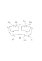
- the mating ring 29 has a cross-sectional shape that is substantially rectangular, and the sealing surface 29S on the seal ring 28 side is formed in a shape that can be in close contact with the surface 28S of the seal ring 28 on substantially the entire surface.
- the sealing surface 29 ⁇ / b> S of the mating ring 29 has a plurality of dynamic pressure generating grooves 30 and 31 that have a substantially L-shaped bent shape symmetrical to each other in the circumferential direction. Is formed.
- the dynamic pressure generating grooves 30, 31 are composed of portions 30a, 31a extending in the radial direction from the outer peripheral surface and portions 30b, 31b extending further in the circumferential direction.
- the portions 30b, 31b extending in the circumferential direction have a groove bottom having a radius. It forms an inclined surface that gradually becomes shallower toward the end on the opposite side to the portions 30a, 31a extending in the direction.
- the depths of the dynamic pressure generating grooves 30 and 31 are formed to a minute depth by fine processing in units of ⁇ m.
- the dynamic pressure generating grooves 30 and 31 shown in FIG. 4 are merely examples, and may be, for example, dimples or Rayleigh steps, and may be any shape as long as the dynamic pressure is generated by relative movement with the seal ring.
- the seal ring 28 is slightly separated from the sealing surface 29S of the mating ring 29 against the pressing force of the coil spring 13 against the mating ring 29. Therefore, the mating ring 29 and the seal ring 28 are separated. Means that a minute gap is formed between the sealing surfaces 28S and 29S, and the shaft sealing function is achieved in this gap while allowing a slight leakage of the sealed fluid.
- the bellows seal 1 of Embodiment 2 employs the structure of a lap joint as a non-contact type seal.
- the bellows seal 1 of the second embodiment configured as described above employs the structure of a lap joint as a non-contact seal, and has a sealing ring as compared with the contact seal of the first embodiment. Wear during rotation of the sealing surface can be prevented.
- the bellows seal 1 of this Embodiment 2 has the following effects in common with Embodiment 1.
- the bellows 11 can be attached in the vicinity of the free length, and the internal stress due to the compression of the bellows 11 can be minimized. That is, since the number of peaks of the bellows 11 can be reduced, the production cost of the bellows 11 can be reduced. Moreover, the bellows seal 1 can be made compact.
- the number of peaks of the bellows 11 is desirably 6 or less, and preferably 4.
- the seal ring 28 has a structure in which the retainer 12 and the lap joint are hermetically connected, the compressive stress due to shrinkage does not act on the seal ring 28 as in the prior art 1, so Breakage can be prevented. Furthermore, since the seal ring 28 has a single structure, a change in flatness due to heat can be minimized.
- the retainer 12 and the seal ring 28 are prevented from rotating on the inner surface of the seal cover 3 by the knock pin 17, the torque associated with the sliding of the seal ring 28 is handled by the knock pin 17 and does not act on the bellows 11. Even if the dynamic torque fluctuates, the bellows 11 is not affected. Therefore, since only the stress due to the sealed fluid and the minimal internal stress due to compression act on the bellows 11, the combined stress can be minimized and the pressure resistance can be improved.
- the present invention can be applied to both the contact type seal and the non-contact type seal. Applicable.
- the seal ring 8 is set by setting the centroid in the axial cross section of the seal ring 8 on the opposite side of the mating ring 9. The sealing performance of the sliding surface between the mating ring 9 and the mating ring 9 can be improved.
- the shift of the centroid to the anti-mate ring side in the axial cross section of the seal ring 8 is changed from the substantially symmetrical main body portion 8A of the seal ring 8 to the mating ring 9.
- the height of the stepped portion 8B protruding to the side is set to be larger than the height of the stepped portion 8C protruding to the retainer 12 side, but the present invention is not limited to this.
- the shape may be asymmetric with a large cross-sectional area on the side of the retainer 12, or the cross-sectional area of the base portion of the step portion 8C may be increased so that the cross-sectional area of the step portion 8C is larger than the cross-sectional area of the step portion 8B. Good.
Abstract
Description
前記第1密封環は、前記ベローズに固定されるリテーナの端面とラップジョイントをもって密封的に連結されると共に、前記第1密封環と前記リテーナとはノックピンにより前記シールカバー側に回り止めされることを特徴としている。
この特徴によれば、スプリングが第1密封環に対して十分な押圧力を有するために、ベローズは、第1密封環に対する押圧力をほどんど有する必要がなく、ベローズを自由長近傍の状態で取り付けることができ、ベローズの圧縮による内部応力を極小とすることができ、ベローズの山数を少なくすることができるためベローズの生産コストを低減することができ、また、ベローズシールをコンパクトにすることができる。
また、第1密封環の摺動に伴うトルクはノックピンが受け持ち、ベローズに作用しないので、摺動トルクが変動してもベローズは影響を受けないため、ベローズには、被密封流体による応力と圧縮による極小の内部応力しか作用しないので、合成応力を極小をとすることができ、耐圧を向上させることができる。
また、第1密封環は、リテーナとラップジョイントをもって密封的に連結される構造であるため、第1密封環には従来技術1のように焼嵌めによる圧縮応力が作用することはないので圧縮応力による破損を防止することができる。さらに、第1密封環は単体構造なので、熱による平面度変化を極小とすることができる。
この特徴によれば、ベローズを介してリテーナ側に突出する段部の内周側の接触部に圧力による押し付け力が付与されるので、第1密封環とリテーナとの密封性を十分に保持することができる。
この特徴によれば、第1密封環は第2密封環に対して外周高で摺接し、第1密封環と第2密封環との摺動面の密封性を向上することができる。
この特徴によれば、第1密封環の図心の第2密封環と反対側へのずれを、第1密封環の機能を損なうことなく達成することができる。
この特徴によれば、リテーナ側に突出する段部とリテーナとの面圧が第1密封環と第2密封環との面圧より大きくなるため、第1密封環とリテーナとの密封性を向上することができる。
(1)スプリングが第1密封環に対して十分な押圧力を有するために、ベローズは、第1密封環に対する押圧力をほどんど有する必要がなく、ベローズを自由長近傍の状態で取り付けることができ、ベローズの圧縮による内部応力を極小とすることができ、ベローズの山数を少なくすることができるためベローズの生産コストを低減することができ、また、ベローズシールをコンパクトにすることができる。
また、第1密封環の摺動に伴うトルクはノックピンが受け持ち、ベローズに作用しないので、摺動トルクが変動してもベローズは影響を受けないため、ベローズには、被密封流体による応力と圧縮による極小の内部応力しか作用しないので、合成応力を極小をとすることができ、耐圧を向上させることができる。
また、第1密封環は、リテーナとラップジョイントをもって密封的に連結される構造であるため、第1密封環には従来技術1のように焼嵌めによる圧縮応力が作用することはないので圧縮応力による破損を防止することができる。さらに、第1密封環は単体構造なので、熱による平面度変化を極小とすることができる。
図1及び図2を参照しながら、本発明の実施の形態1に係るベローズシールを説明する。
図1において、参照符号1は、石油精製、石油化学および製鉄化学等において200℃を越えるような高圧・高温液、たとえば、石油精製プラントの減圧蒸留設備の熱油を扱うポンプ等のハンジング2の機内側を機外側に対して密封するためのベローズシールである。なお、図中右側が機内側(高圧流体側)、図中左側が機外側(大気側)である。
シールリングの軸方向の断面における図心のメイティングリング9と反対側へのずれは、シールリング8の略対称な形状の本体部8Aからメイティングリング9側に突出する段部8Bの高さがリテーナ12側に突出する段部8Cの高さより大きく設定されていることにより行われるため、シールリングの機能を損なうことなく達成することができる。
図3及び図4を参照しながら、本発明の実施の形態2に係るベローズシールを説明する。
実施の形態2に係るベローズシールは、第1密封環を構成するシールリング及び第2密封環を構成するメイティングリングの形状・構造において実施の形態1と相違するが、その他は実施の形態1と同じであり、図3及び図4において、図1及び図2と同じ符号は同じ部材を指しており、重複する説明は省略する。
以下、実施の形態1と相違する部分について主に説明する。
動圧発生溝30、31の深さは、μm単位の微細加工によって微小深さに形成されている。
なお、図4に示す動圧発生溝30、31は、一例に過ぎず、例えば、ディンプルあるいはレイリーステップでもよく、要はシールリングとの相対移動により動圧を発生する形状であればよい。
このように、実施の形態2のベローズシール1は、ラップジョイントの構造を非接触式シールに採用したものである。
すなわち、ベローズ11が伸縮する回転軸4の軸方向に沿ってスプリング13がシールカバー3の内周側に取り付けられており、スプリング13がリテーナ12を介してシールリング8に対して十分な押圧力を有するため、ベローズ11は、シールリング8に対する押圧力をほどんど有する必要がない。そのため、ベローズ11を自由長近傍の状態で取り付けることができ、ベローズ11の圧縮による内部応力を極小とすることができる。つまり、ベローズ11の山数を少なくすることができるために、ベローズ11の生産コストを低減することができる。また、ベローズシール1をコンパクトにすることができる。ベローズ11の山数は、6山以下が望ましく、好適には4山である。
その際、実施の形態1のように、接触式シールの場合は、シールリング8の軸方向の断面における図心がメイティングリング9と反対側に位置するように設定することにより、シールリング8とメイティングリング9との摺動面の密封性を向上することができるというものである。
2 ハウジング
3 シールカバー
4 回転軸
5 スリーブカラー
6 スリーブ
7 Oリング
8、28 シールリング(第1密封環)
8A、28A シールリングの本体部
8B メイティングリング側に突出する段部
8C、28C リテーナ側に突出する段部
8S シールリングの摺動面
28S シールリングの密封面
9、29 メイティングリング(第2密封環)
9S メイティングリングの摺動面
29S メイティングリングの密封面
10 アダプタ
11 ベローズ
12 リテーナ
13 スプリング
14 Oリング
15 Oリング
17 ノックピン
18 スナップリング
30、31 動圧発生溝
L メイティングリング側からシールリングの図心までの距離
b メイティングリングとリテーナとの間の距離
DLI シールリングのリテーナ側に突出する段部の内径
Dm ベローズの中心径
W1 シールリングのメイティングリング側に突出する段部の径方向の幅
W2 シールリングのリテーナ側に突出する段部の径方向の幅
Claims (5)
- ハウジングと回転軸との間に形成され軸封部に装着されるシールカバーと、
前記シールカバーの内周側に軸方向移動自在に配置される第1密封環と、
前記回転軸に固定される第2密封環と、
前記シールカバーの内周側に取り付けられ、前記シールカバーと前記第1密封環との間に軸方向伸縮自在に取り付けられるベローズと、
前記シールカバーの内周側に配置され、前記第1密封環を前記第2密封環の方向に押圧するスプリングと、を具備し、
前記第1密封環は、前記ベローズに固定されるリテーナの端面とラップジョイントをもって密封的に連結されると共に、前記第1密封環と前記リテーナとはノックピンにより前記シールカバー側に回り止めされることを特徴とするベローズシール。 - 前記第1密封環は、リテーナ側に突出する段部を備え、前記リテーナ側に突出する段部の内径は前記ベローズの中心径以上に設定されることを特徴とする請求項1記載のベローズシール。
- 前記第1密封環は、軸方向の断面における図心が前記第2密封環とリテーナとの間の中間より前記第2密封環と反対側に位置するように設定されることを特徴とする請求項1又は2記載のベローズシール。
- 前記第1密封環は、その本体部が前記図心に対して略対称な形状に形成され、前記本体部から第2密封環側に突出する段部を備え、前記第2密封環側に突出する段部の高さが前記リテーナ側に突出する段部の高さより大きく設定されることを特徴とする請求項2又は3記載のベローズシール。
- 前記第1密封環の前記リテーナ側に突出する段部の径方向の幅は前記第2密封環側に突出する段部の径方向の幅より小さく設定されることを特徴とする請求項4記載のベローズシール。
Priority Applications (4)
| Application Number | Priority Date | Filing Date | Title |
|---|---|---|---|
| JP2014542085A JP6158205B2 (ja) | 2012-10-19 | 2013-10-10 | ベローズシール |
| CN201380048857.4A CN104685272A (zh) | 2012-10-19 | 2013-10-10 | 波纹管密封件 |
| EP13847540.5A EP2910823A4 (en) | 2012-10-19 | 2013-10-10 | bellows seal |
| US14/429,989 US20150240950A1 (en) | 2012-10-19 | 2013-10-10 | Bellows Seal |
Applications Claiming Priority (2)
| Application Number | Priority Date | Filing Date | Title |
|---|---|---|---|
| JP2012-232435 | 2012-10-19 | ||
| JP2012232435 | 2012-10-19 |
Publications (1)
| Publication Number | Publication Date |
|---|---|
| WO2014061543A1 true WO2014061543A1 (ja) | 2014-04-24 |
Family
ID=50488110
Family Applications (1)
| Application Number | Title | Priority Date | Filing Date |
|---|---|---|---|
| PCT/JP2013/077578 WO2014061543A1 (ja) | 2012-10-19 | 2013-10-10 | ベローズシール |
Country Status (5)
| Country | Link |
|---|---|
| US (1) | US20150240950A1 (ja) |
| EP (1) | EP2910823A4 (ja) |
| JP (1) | JP6158205B2 (ja) |
| CN (1) | CN104685272A (ja) |
| WO (1) | WO2014061543A1 (ja) |
Cited By (4)
| Publication number | Priority date | Publication date | Assignee | Title |
|---|---|---|---|---|
| WO2016006535A1 (ja) * | 2014-07-11 | 2016-01-14 | イーグル工業株式会社 | メカニカルシール |
| WO2016035860A1 (ja) * | 2014-09-04 | 2016-03-10 | イーグル工業株式会社 | メカニカルシール |
| WO2016186019A1 (ja) * | 2015-05-19 | 2016-11-24 | イーグル工業株式会社 | 摺動部品 |
| CN108506496A (zh) * | 2018-04-03 | 2018-09-07 | 北京化工大学 | 一种隔离型动压密封装置及机械设备 |
Families Citing this family (17)
| Publication number | Priority date | Publication date | Assignee | Title |
|---|---|---|---|---|
| EP2886914A4 (en) * | 2012-08-22 | 2016-07-27 | Eagle Ind Co Ltd | MECHANICAL DOUBLE SEAL |
| WO2014050920A1 (ja) * | 2012-09-29 | 2014-04-03 | イーグル工業株式会社 | 摺動部品 |
| WO2014142265A1 (ja) * | 2013-03-14 | 2014-09-18 | イーグルブルグマンジャパン株式会社 | メカニカルシール装置 |
| DE102016200821B3 (de) * | 2016-01-21 | 2017-05-11 | Eagleburgmann Germany Gmbh & Co. Kg | Gleitringdichtungsanordnung mit rückseitiger Abdichtung |
| JP6707021B2 (ja) * | 2016-12-22 | 2020-06-10 | 株式会社日立産機システム | スクリュー圧縮機 |
| WO2019069887A1 (ja) * | 2017-10-03 | 2019-04-11 | イーグル工業株式会社 | 摺動部品 |
| EP3832178B1 (en) * | 2018-08-01 | 2024-05-01 | Eagle Industry Co., Ltd. | Slide component |
| EP3842673A4 (en) | 2018-08-24 | 2022-05-04 | Eagle Industry Co., Ltd. | SLIDING ELEMENT |
| KR102589959B1 (ko) | 2018-11-30 | 2023-10-17 | 이구루코교 가부시기가이샤 | 슬라이딩 부품 |
| JP7345998B2 (ja) | 2018-12-21 | 2023-09-19 | イーグル工業株式会社 | 摺動部品 |
| US11933405B2 (en) | 2019-02-14 | 2024-03-19 | Eagle Industry Co., Ltd. | Sliding component |
| CN109751277B (zh) * | 2019-02-27 | 2024-02-13 | 沈阳北碳密封有限公司 | 自吸泵用正负压工况机械密封 |
| EP4006368A4 (en) | 2019-07-26 | 2023-08-16 | Eagle Industry Co., Ltd. | SLIDING ELEMENT |
| CN110509066B (zh) * | 2019-07-30 | 2024-05-03 | 航天晨光股份有限公司 | 一种小口径环形金属波纹管切割敲波机构 |
| US11396947B2 (en) * | 2019-12-05 | 2022-07-26 | Eaton Intelligent Power Limited | Face seal with welded bellows |
| GB2597764B (en) * | 2020-08-04 | 2023-11-01 | Crane John Uk Ltd | Apparatus and method |
| US11608751B2 (en) * | 2021-03-19 | 2023-03-21 | Raytheon Technologies Corporation | Self-guiding carbon seal system |
Citations (8)
| Publication number | Priority date | Publication date | Assignee | Title |
|---|---|---|---|---|
| JPS477555U (ja) * | 1971-02-19 | 1972-09-27 | ||
| JPH0234871U (ja) * | 1988-08-31 | 1990-03-06 | ||
| JPH0631252A (ja) | 1992-07-22 | 1994-02-08 | Ebara Corp | 洗浄装置 |
| JPH0932932A (ja) * | 1995-07-20 | 1997-02-07 | Eagle Ii G & G Aerospace Kk | 端面型回転軸シール装置 |
| JP2009501302A (ja) * | 2005-07-14 | 2009-01-15 | ブルクマン インダストリーズ ゲセルシャフト ミト ベシュレンクテル ハフツング ウント コンパニー コマンディトゲセルシャフト | スライドリングシール構造 |
| WO2010004809A1 (ja) | 2008-07-07 | 2010-01-14 | イーグル工業株式会社 | メカニカルシール装置 |
| JP2010216491A (ja) * | 2009-03-13 | 2010-09-30 | Eagle Ind Co Ltd | 高温用デッドエンドシール |
| JP2012102784A (ja) * | 2010-11-09 | 2012-05-31 | Nippon Pillar Packing Co Ltd | メカニカルシール |
Family Cites Families (18)
| Publication number | Priority date | Publication date | Assignee | Title |
|---|---|---|---|---|
| US2785913A (en) * | 1954-04-20 | 1957-03-19 | Crane Packing Co | Rotary mechanical seal with ceramic seat |
| US3776560A (en) * | 1971-03-04 | 1973-12-04 | Borg Warner | Bellows type fluid seal |
| US4105040A (en) * | 1977-06-27 | 1978-08-08 | Chester Arnold M | Temperature responsive valve seal |
| CA1126305A (en) * | 1979-05-11 | 1982-06-22 | Toshio Kawamura | Seal assembly for a linkage |
| JPS58118376A (ja) * | 1982-01-07 | 1983-07-14 | Nippon Pillar Packing Co Ltd | メカニカルシ−ル |
| FR2589955B1 (fr) * | 1985-11-08 | 1989-12-08 | Sealol | Dispositif d'etancheite de turbopompe |
| JP2648816B2 (ja) * | 1988-05-10 | 1997-09-03 | イーグル工業株式会社 | 円筒面シール |
| JPH0631252Y2 (ja) * | 1989-12-08 | 1994-08-22 | イーグル工業株式会社 | ベローズ型メカニカルシール |
| US5360076A (en) * | 1992-04-03 | 1994-11-01 | Hughes Tool Company | Dual metal face seal with single recessed energizer |
| JP2563081B2 (ja) * | 1994-03-22 | 1996-12-11 | 日本ピラー工業株式会社 | 非接触形軸封装置 |
| JP3650954B2 (ja) * | 1998-09-18 | 2005-05-25 | イーグル工業株式会社 | 高速用非接触型メカニカルシール |
| US7194803B2 (en) * | 2001-07-05 | 2007-03-27 | Flowserve Management Company | Seal ring and method of forming micro-topography ring surfaces with a laser |
| JP2003074714A (ja) * | 2001-08-31 | 2003-03-12 | Eagle Ind Co Ltd | メカニカルシール装置 |
| JP4111698B2 (ja) * | 2001-08-31 | 2008-07-02 | イーグル工業株式会社 | メカニカルシール装置 |
| US6902168B2 (en) * | 2002-03-19 | 2005-06-07 | Eagle Industry Co., Ltd. | Sliding element |
| US20060022411A1 (en) * | 2004-07-15 | 2006-02-02 | Beardsley M B | Sealing system |
| WO2006115118A1 (ja) * | 2005-04-22 | 2006-11-02 | Eagle Industry Co., Ltd. | メカニカルシール装置、摺動部品およびその製造方法 |
| CN102405365B (zh) * | 2009-04-23 | 2015-04-08 | 伊格尔工业股份有限公司 | 机械密封装置 |
-
2013
- 2013-10-10 JP JP2014542085A patent/JP6158205B2/ja active Active
- 2013-10-10 US US14/429,989 patent/US20150240950A1/en not_active Abandoned
- 2013-10-10 WO PCT/JP2013/077578 patent/WO2014061543A1/ja active Application Filing
- 2013-10-10 CN CN201380048857.4A patent/CN104685272A/zh active Pending
- 2013-10-10 EP EP13847540.5A patent/EP2910823A4/en not_active Withdrawn
Patent Citations (8)
| Publication number | Priority date | Publication date | Assignee | Title |
|---|---|---|---|---|
| JPS477555U (ja) * | 1971-02-19 | 1972-09-27 | ||
| JPH0234871U (ja) * | 1988-08-31 | 1990-03-06 | ||
| JPH0631252A (ja) | 1992-07-22 | 1994-02-08 | Ebara Corp | 洗浄装置 |
| JPH0932932A (ja) * | 1995-07-20 | 1997-02-07 | Eagle Ii G & G Aerospace Kk | 端面型回転軸シール装置 |
| JP2009501302A (ja) * | 2005-07-14 | 2009-01-15 | ブルクマン インダストリーズ ゲセルシャフト ミト ベシュレンクテル ハフツング ウント コンパニー コマンディトゲセルシャフト | スライドリングシール構造 |
| WO2010004809A1 (ja) | 2008-07-07 | 2010-01-14 | イーグル工業株式会社 | メカニカルシール装置 |
| JP2010216491A (ja) * | 2009-03-13 | 2010-09-30 | Eagle Ind Co Ltd | 高温用デッドエンドシール |
| JP2012102784A (ja) * | 2010-11-09 | 2012-05-31 | Nippon Pillar Packing Co Ltd | メカニカルシール |
Non-Patent Citations (1)
| Title |
|---|
| See also references of EP2910823A4 * |
Cited By (9)
| Publication number | Priority date | Publication date | Assignee | Title |
|---|---|---|---|---|
| WO2016006535A1 (ja) * | 2014-07-11 | 2016-01-14 | イーグル工業株式会社 | メカニカルシール |
| CN106471295A (zh) * | 2014-07-11 | 2017-03-01 | 伊格尔工业股份有限公司 | 机械密封 |
| JPWO2016006535A1 (ja) * | 2014-07-11 | 2017-06-01 | イーグル工業株式会社 | メカニカルシール |
| WO2016035860A1 (ja) * | 2014-09-04 | 2016-03-10 | イーグル工業株式会社 | メカニカルシール |
| JPWO2016035860A1 (ja) * | 2014-09-04 | 2017-06-15 | イーグル工業株式会社 | メカニカルシール |
| US10054230B2 (en) | 2014-09-04 | 2018-08-21 | Eagles Industry Co., Ltd. | Mechanical seal |
| WO2016186019A1 (ja) * | 2015-05-19 | 2016-11-24 | イーグル工業株式会社 | 摺動部品 |
| CN108506496A (zh) * | 2018-04-03 | 2018-09-07 | 北京化工大学 | 一种隔离型动压密封装置及机械设备 |
| CN108506496B (zh) * | 2018-04-03 | 2023-06-13 | 北京化工大学 | 一种隔离型动压密封装置及机械设备 |
Also Published As
| Publication number | Publication date |
|---|---|
| EP2910823A4 (en) | 2016-05-18 |
| CN104685272A (zh) | 2015-06-03 |
| JPWO2014061543A1 (ja) | 2016-09-05 |
| JP6158205B2 (ja) | 2017-07-05 |
| EP2910823A1 (en) | 2015-08-26 |
| US20150240950A1 (en) | 2015-08-27 |
Similar Documents
| Publication | Publication Date | Title |
|---|---|---|
| JP6158205B2 (ja) | ベローズシール | |
| EP2799752B1 (en) | Multi-port rotary joint | |
| US10371300B2 (en) | Rotary joint | |
| JP5514107B2 (ja) | メカニカルシール装置 | |
| WO2014192761A1 (ja) | メカニカルシール装置 | |
| US9447885B2 (en) | Double mechanical seal device | |
| WO2016006535A1 (ja) | メカニカルシール | |
| US11221074B2 (en) | Mechanical seal | |
| JP5914682B2 (ja) | 密封装置 | |
| US10816045B2 (en) | Clutch structure | |
| WO2018180307A1 (ja) | シール材の配置構造 | |
| JP7353721B2 (ja) | メカニカルシール用の二次シール | |
| JP6612092B2 (ja) | メカニカルシール | |
| JP7404358B2 (ja) | メカニカルシール | |
| CN104533827B (zh) | 一种符合ansi标准泵腔的机械密封 | |
| JP6256864B2 (ja) | スライドリングシール | |
| JP6240038B2 (ja) | メカニカルシール | |
| US11313508B2 (en) | Radial positioning device | |
| US10557554B2 (en) | Mechanical seal with high pressure high temperature secondary seal | |
| WO2018207747A1 (ja) | メカニカルシール | |
| JP2010261573A (ja) | 耐蝕性ベローズ形メカニカルシール | |
| JP2023526039A (ja) | 高温用途用メカニカルシール構造 | |
| JP5695531B2 (ja) | 端面接触形メカニカルシール | |
| JPH0416029Y2 (ja) | ||
| PL220034B1 (pl) | Mechaniczne uszczelnienie obrotowe |
Legal Events
| Date | Code | Title | Description |
|---|---|---|---|
| 121 | Ep: the epo has been informed by wipo that ep was designated in this application |
Ref document number: 13847540 Country of ref document: EP Kind code of ref document: A1 |
|
| ENP | Entry into the national phase |
Ref document number: 2014542085 Country of ref document: JP Kind code of ref document: A |
|
| WWE | Wipo information: entry into national phase |
Ref document number: 2013847540 Country of ref document: EP |
|
| WWE | Wipo information: entry into national phase |
Ref document number: 14429989 Country of ref document: US |
|
| NENP | Non-entry into the national phase |
Ref country code: DE |