WO2014058008A1 - 船体抵抗低減システムおよび船体の抵抗低減方法 - Google Patents
船体抵抗低減システムおよび船体の抵抗低減方法 Download PDFInfo
- Publication number
- WO2014058008A1 WO2014058008A1 PCT/JP2013/077583 JP2013077583W WO2014058008A1 WO 2014058008 A1 WO2014058008 A1 WO 2014058008A1 JP 2013077583 W JP2013077583 W JP 2013077583W WO 2014058008 A1 WO2014058008 A1 WO 2014058008A1
- Authority
- WO
- WIPO (PCT)
- Prior art keywords
- compressor
- exhaust
- exhaust turbine
- exhaust gas
- air
- Prior art date
- Legal status (The legal status is an assumption and is not a legal conclusion. Google has not performed a legal analysis and makes no representation as to the accuracy of the status listed.)
- Ceased
Links
Images

Classifications
-
- B—PERFORMING OPERATIONS; TRANSPORTING
- B63—SHIPS OR OTHER WATERBORNE VESSELS; RELATED EQUIPMENT
- B63B—SHIPS OR OTHER WATERBORNE VESSELS; EQUIPMENT FOR SHIPPING
- B63B1/00—Hydrodynamic or hydrostatic features of hulls or of hydrofoils
- B63B1/32—Other means for varying the inherent hydrodynamic characteristics of hulls
- B63B1/34—Other means for varying the inherent hydrodynamic characteristics of hulls by reducing surface friction
- B63B1/38—Other means for varying the inherent hydrodynamic characteristics of hulls by reducing surface friction using air bubbles or air layers gas filled volumes
-
- F—MECHANICAL ENGINEERING; LIGHTING; HEATING; WEAPONS; BLASTING
- F01—MACHINES OR ENGINES IN GENERAL; ENGINE PLANTS IN GENERAL; STEAM ENGINES
- F01N—GAS-FLOW SILENCERS OR EXHAUST APPARATUS FOR MACHINES OR ENGINES IN GENERAL; GAS-FLOW SILENCERS OR EXHAUST APPARATUS FOR INTERNAL-COMBUSTION ENGINES
- F01N5/00—Exhaust or silencing apparatus combined or associated with devices profiting by exhaust energy
- F01N5/04—Exhaust or silencing apparatus combined or associated with devices profiting by exhaust energy the devices using kinetic energy
-
- F—MECHANICAL ENGINEERING; LIGHTING; HEATING; WEAPONS; BLASTING
- F02—COMBUSTION ENGINES; HOT-GAS OR COMBUSTION-PRODUCT ENGINE PLANTS
- F02B—INTERNAL-COMBUSTION PISTON ENGINES; COMBUSTION ENGINES IN GENERAL
- F02B37/00—Engines characterised by provision of pumps driven at least for part of the time by exhaust
- F02B37/001—Engines characterised by provision of pumps driven at least for part of the time by exhaust using exhaust drives arranged in parallel
-
- F—MECHANICAL ENGINEERING; LIGHTING; HEATING; WEAPONS; BLASTING
- F02—COMBUSTION ENGINES; HOT-GAS OR COMBUSTION-PRODUCT ENGINE PLANTS
- F02B—INTERNAL-COMBUSTION PISTON ENGINES; COMBUSTION ENGINES IN GENERAL
- F02B37/00—Engines characterised by provision of pumps driven at least for part of the time by exhaust
- F02B37/007—Engines characterised by provision of pumps driven at least for part of the time by exhaust with exhaust-driven pumps arranged in parallel, e.g. at least one pump supplying alternatively
-
- F—MECHANICAL ENGINEERING; LIGHTING; HEATING; WEAPONS; BLASTING
- F02—COMBUSTION ENGINES; HOT-GAS OR COMBUSTION-PRODUCT ENGINE PLANTS
- F02B—INTERNAL-COMBUSTION PISTON ENGINES; COMBUSTION ENGINES IN GENERAL
- F02B63/00—Adaptations of engines for driving pumps, hand-held tools or electric generators; Portable combinations of engines with engine-driven devices
- F02B63/04—Adaptations of engines for driving pumps, hand-held tools or electric generators; Portable combinations of engines with engine-driven devices for electric generators
-
- F—MECHANICAL ENGINEERING; LIGHTING; HEATING; WEAPONS; BLASTING
- F02—COMBUSTION ENGINES; HOT-GAS OR COMBUSTION-PRODUCT ENGINE PLANTS
- F02G—HOT GAS OR COMBUSTION-PRODUCT POSITIVE-DISPLACEMENT ENGINE PLANTS; USE OF WASTE HEAT OF COMBUSTION ENGINES; NOT OTHERWISE PROVIDED FOR
- F02G5/00—Profiting from waste heat of combustion engines, not otherwise provided for
- F02G5/02—Profiting from waste heat of exhaust gases
-
- B—PERFORMING OPERATIONS; TRANSPORTING
- B63—SHIPS OR OTHER WATERBORNE VESSELS; RELATED EQUIPMENT
- B63B—SHIPS OR OTHER WATERBORNE VESSELS; EQUIPMENT FOR SHIPPING
- B63B1/00—Hydrodynamic or hydrostatic features of hulls or of hydrofoils
- B63B1/32—Other means for varying the inherent hydrodynamic characteristics of hulls
- B63B1/34—Other means for varying the inherent hydrodynamic characteristics of hulls by reducing surface friction
- B63B1/38—Other means for varying the inherent hydrodynamic characteristics of hulls by reducing surface friction using air bubbles or air layers gas filled volumes
- B63B2001/385—Other means for varying the inherent hydrodynamic characteristics of hulls by reducing surface friction using air bubbles or air layers gas filled volumes using exhaust gas
-
- F—MECHANICAL ENGINEERING; LIGHTING; HEATING; WEAPONS; BLASTING
- F02—COMBUSTION ENGINES; HOT-GAS OR COMBUSTION-PRODUCT ENGINE PLANTS
- F02B—INTERNAL-COMBUSTION PISTON ENGINES; COMBUSTION ENGINES IN GENERAL
- F02B63/00—Adaptations of engines for driving pumps, hand-held tools or electric generators; Portable combinations of engines with engine-driven devices
- F02B63/06—Adaptations of engines for driving pumps, hand-held tools or electric generators; Portable combinations of engines with engine-driven devices for pumps
-
- Y—GENERAL TAGGING OF NEW TECHNOLOGICAL DEVELOPMENTS; GENERAL TAGGING OF CROSS-SECTIONAL TECHNOLOGIES SPANNING OVER SEVERAL SECTIONS OF THE IPC; TECHNICAL SUBJECTS COVERED BY FORMER USPC CROSS-REFERENCE ART COLLECTIONS [XRACs] AND DIGESTS
- Y02—TECHNOLOGIES OR APPLICATIONS FOR MITIGATION OR ADAPTATION AGAINST CLIMATE CHANGE
- Y02T—CLIMATE CHANGE MITIGATION TECHNOLOGIES RELATED TO TRANSPORTATION
- Y02T10/00—Road transport of goods or passengers
- Y02T10/10—Internal combustion engine [ICE] based vehicles
- Y02T10/12—Improving ICE efficiencies
-
- Y—GENERAL TAGGING OF NEW TECHNOLOGICAL DEVELOPMENTS; GENERAL TAGGING OF CROSS-SECTIONAL TECHNOLOGIES SPANNING OVER SEVERAL SECTIONS OF THE IPC; TECHNICAL SUBJECTS COVERED BY FORMER USPC CROSS-REFERENCE ART COLLECTIONS [XRACs] AND DIGESTS
- Y02—TECHNOLOGIES OR APPLICATIONS FOR MITIGATION OR ADAPTATION AGAINST CLIMATE CHANGE
- Y02T—CLIMATE CHANGE MITIGATION TECHNOLOGIES RELATED TO TRANSPORTATION
- Y02T70/00—Maritime or waterways transport
- Y02T70/10—Measures concerning design or construction of watercraft hulls
Definitions
- the present invention relates to a hull resistance reduction system and a hull resistance reduction method that are suitable for use, for example, in a general-purpose ship.
- Patent Document 1 discloses a hull resistance reduction device that releases air bubbles on the surface of the hull of a ship in water to reduce frictional resistance during navigation.
- the ship resistance reduction device is driven by the exhaust gas from the main engine of the ship, and is provided with a supercharger that pumps combustion air to the main engine, and for combustion supplied from the supercharger to the main engine
- the air is extracted and discharged to the outer surface of the vessel, and the turbocharger is provided with a variable nozzle capable of adjusting the exhaust flow velocity in two stages, and the variable nozzle for extracting air for combustion and released to the outer surface of the ship It is shown that the variable nozzle is opened if the combustion air is not extracted and released to the outer surface of the ship.
- Patent Document 1 describes that a part of scavenging of a diesel main engine is introduced to the bottom of a ship.
- the pressure of scavenging changes with engine load, the pressure and amount of air of air required for bubble emission are substantially constant. Therefore, there is a risk that the pressure and the amount of air are insufficient at low loads, and the air that becomes bubbles must be depressurized at high loads.
- an auxiliary compressor is used to compensate for the decrease in pressure and air amount at low load operation. This increases the cost and cost of fuel. In addition, it is difficult to control the balance between the auxiliary compressor and the scavenging air.
- the present invention has been made in view of such circumstances, and it is possible to compress air that becomes air bubbles using energy of exhaust gas and to stably supply the air to the outer surface of the underwater hull. It is an object of the present invention to provide a reduction system and a method of reducing the resistance of a ship.
- a hull resistance reduction system and a hull resistance reduction method of the present invention adopt the following means.
- a ship body resistance reduction system comprising: a main engine; an exhaust turbine compressor operated by introducing a part of exhaust gas of the main engine; and a compression introduced from the exhaust turbine compressor And a discharge nozzle for guiding air to the outer surface of the ship, wherein the exhaust turbine compressor is provided with an exhaust turbine rotationally driven by the introduced exhaust gas, and a rotational driving force of the exhaust turbine.
- the compressor includes: a compressor that compresses air; and a motor generator that generates electricity from the exhaust turbine and boosts the compressor.
- an exhaust turbine compressor is provided separately from the turbocharger used in the main engine, for compressing air that becomes air bubbles that reduces the hull resistance.
- a part of exhaust gas extracted from an exhaust gas system for example, an exhaust gas manifold
- Exhaust gas extracted from the exhaust gas system is supplied to the exhaust turbine of the turbocharger.
- the exhaust gas turbine drives the exhaust gas turbine of the turbocharger so that the compressor can pressurize the air to be bubbles.
- the compressed air air that becomes air bubbles
- the friction between the hull and the sea can be stably reduced.
- a hybrid turbocharger in which a motor generator is provided in the turbocharger is suitably used.
- the compressor when the pressure of the compressed air discharged from the discharge nozzle falls below a predetermined value, the compressor is energized by the motor generator.
- the motor generator when the pressure of the compressed air discharged from the discharge nozzle falls below a predetermined value, the motor generator can be operated as a motor to energize the compressor. As a result, the energy of the exhaust gas led to the exhaust turbine compressor can be recovered sufficiently, and the motor generator can be operated supplementary, and the consumption of power for driving the motor generator can be suppressed. .
- the hull resistance reduction system operates the motor generator as a generator to supply electric power to the ship when the pressure of the compressed air discharged from the discharge nozzle exceeds a predetermined value. Do.
- a desired compressed air pressure can be obtained only by the energy of the exhaust gas led to the exhaust turbine compressor.
- the energy of the excess exhaust gas can be recovered by the power generation of the motor generator.
- a control valve is provided in the exhaust bypass pipe that guides part of the exhaust gas of the main engine to the exhaust turbine compressor.
- the flow rate of the exhaust gas flowing in the exhaust bypass pipe can be adjusted by providing the control valve in the exhaust bypass pipe.
- the motor generator is driven at variable speed by inverter control.
- the motor generator is in inverter control.
- the rotational frequency can be made variable according to the state of the main engine and the like, and energy saving control can be performed which can suppress the consumption of electric power.
- a method of reducing resistance of a hull according to a sixth aspect of the present invention comprises the steps of: driving an exhaust turbine compressor by introducing a part of exhaust gas from a main engine; and driving the compressor by driving the exhaust turbine. And reducing the pressure of the air discharged from the discharge nozzle.
- the method for reducing the resistance of a ship comprising the steps of: compressing the air; and guiding the compressed air to the outer surface of the underwater vessel by means of the discharge nozzle.
- the method further includes the step of energizing the compressor by a motor generator when the value is below a predetermined value.
- a method of reducing resistance of a hull according to a seventh aspect of the present invention comprises the steps of: driving an exhaust turbine compressor by introducing a part of exhaust gas from a main engine; and driving the compressor by driving the exhaust turbine. And reducing the pressure of the air discharged from the discharge nozzle.
- the method for reducing the resistance of a ship comprising the steps of: compressing the air; and guiding the compressed air to the outer surface of the underwater vessel by means of the discharge nozzle. If the value exceeds the predetermined value, the method further includes the step of operating the motor generator as a generator to supply power to the ship.
- the power required to compress air that is to be air bubbles can be reduced by the effect of exhaust heat recovery using a part of the energy of exhaust gas for compression of air. it can.
- an exhaust turbine compressor is provided to compress air as air bubbles.
- a part of exhaust gas extracted from an exhaust gas system of a main engine is used.
- the exhaust gas can drive the turbine of the exhaust turbine compressor to stably pressurize the air that is the air bubbles from the compressor.
- compressed air air that becomes air bubbles
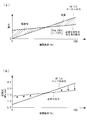
- FIG. 2 is a graph showing the relationship between the engine load and the scavenging pressure in the hull resistance reduction system according to the embodiment of the present invention.
- the hull resistance reduction system 30 discharges micro air bubbles onto the outer surface of the underwater vessel of the ship traveling above the water, particularly onto the outer surface of the bottom of the hull which is submerged below the waterline and when underwater. It is a system which reduces the frictional resistance of the hull by sailing.
- FIG. 1 shows a schematic configuration of a hull resistance reduction system 30 according to the present invention.
- the main engine 1 provided in the hull resistance reduction system 30 includes an exhaust gas system 2 (exhaust manifold), a supercharger 5, an air cooler 4 and a scavenging chamber 3.
- an exhaust turbine compressor 20 is provided separately from the supercharger 5 provided in the main engine 1.
- An exhaust bypass pipe 9 through which the exhaust gas extracted from the exhaust gas system 2 flows is connected to the exhaust turbine 20 b side of the exhaust turbine compressor 20.
- the compressor 20a, the exhaust turbine 20b, and the motor generator 21 of the exhaust turbine compressor 20 are connected by a rotating shaft 20c, and a discharge nozzle 24 extending to the surface of the hull outside the water is connected to the discharge side of the compressor 20a.
- the main engine 1 is, for example, a diesel engine for driving a main engine provided on a ship.
- the main engine 1 is driven by supplying fuel introduced from a fuel injection pump (not shown) and compressed air introduced from the turbocharger 5 into the cylinder.
- the supercharger 5 is provided between the exhaust gas system 2 of the main engine 1 and the scavenging chamber 3.
- the turbocharger 5 has a turbine 5b rotationally driven by exhaust gas led from the main engine 1, a rotating shaft 5c having one end connected to the turbine 5b, and a compressor 5a connected to the other end of the rotating shaft 5c. Is equipped.
- the rotational force obtained by the turbine 5b is transmitted through the rotation shaft 5c to be rotationally driven, and the compressor 5a compresses intake air taken in from an intake port (not shown).
- the compressed air compressed by the compressor 5 a is cooled by the air cooler 4 and then supplied to the scavenging chamber 3 of the main engine 1.
- the turbine 5 b is composed of a turbine blade that receives and rotates exhaust gas, and is housed in a turbine casing.
- the turbine casing includes a turbocharger suction pipe 6 to which the exhaust gas is led from the exhaust gas system 2 (exhaust gas manifold) of the main engine 1, and a turbocharger outlet pipe which guides the exhaust gas passing through the turbine blade to the outside of the turbine 5b. Connected to 8 and.
- the supercharger outlet pipe 8 is connected to an exhaust pipe 10 for exhausting the fuel to the outside of the ship.
- the compressor 5a has a suction pipe (not shown) connected to the suction side of the compressor 5a, and is connected to one end of a discharge pipe 7 through which compressed air flows on the discharge side of the compressor 5a. Further, an air cooler 4 is connected to the other end of the discharge pipe 7, and the air cooler 4 is connected to the scavenging chamber 3.
- An exhaust gas bypass pipe 9 is connected to the exhaust gas system 2 of the main engine 1, and the exhaust gas bypass pipe 9 is connected to an exhaust turbine 20b of an exhaust turbine compressor 20 driven by the extracted exhaust gas. Further, a control valve 11 is provided in the exhaust bypass pipe 9.
- the exhaust turbine compressor 20 has the same configuration as the turbocharger 5 except that it has a motor generator 21.
- a turbocharger outlet pipe 23 is connected to the discharge side of the exhaust turbine 20b of the exhaust turbine compressor 20. It is done.
- a discharge nozzle 24 extending to the surface of the hull outside the water is connected on the side of the compressor 20a of the exhaust turbine compressor 20, a discharge nozzle 24 extending to the surface of the hull outside the water is connected.
- the other end of the discharge nozzle 24 is provided, for example, on the surface of the ship such as the bottom of the ship, and compressed air (air that becomes air bubbles) is made into air bubbles from an opening opened to the surface of the ship Connected to a gas jet (not shown) that is jetted to the
- a gas jet not shown
- the compressor 20a, the exhaust turbine 20b and the motor generator 21 of the exhaust turbine compressor 20 are connected by a coaxial rotating shaft 20c.
- the exhaust turbine compressor 20 includes one motor generator 21 driven by the exhaust turbine compressor 20 to generate electric power.
- the exhaust turbine compressor 20 is disposed in series by connecting the motor generator 21, the compressor 20a, and the exhaust turbine 20b by the rotary shaft 20c, and the motor generator 21 is driven by the exhaust turbine compressor 20, It is generated.
- the exhaust gas extracted from the exhaust manifold 2 for collectively delivering the exhaust gas from a plurality of cylinders (not shown) to the exhaust pipe 10 is supercharged through the supercharger suction pipe 6. It is led to the 5 turbine 5b.
- the exhaust gas supplied to the turbine 5b rotationally drives the turbine 5b, and the rotational force obtained by the turbine 5b is transmitted via the rotation shaft 5c to rotationally drive the compressor 5a. This compresses the intake air.
- the compressed air compressed by the air compressor is supplied to the scavenging chamber 3 of the main engine 1 after being cooled by the air cooler 4.
- the exhaust gas supplied to the turbine 5 b is led from the turbocharger outlet piping 8 to the exhaust pipe 10 after rotating the rotating shaft 5 c.
- the exhaust gas discharged from the exhaust pipe 10 is discharged to the atmosphere from a chimney (not shown) after being subjected to necessary exhaust gas treatment.
- the exhaust turbine 20 b of the exhaust turbine compressor 20 is driven by part of the exhaust gas led via the exhaust bypass pipe 9.
- the rotational force obtained by the exhaust turbine 20 b is transmitted to the compressor 20 a and the motor generator 21 coaxial with the exhaust turbine 20 b of the exhaust turbine compressor 20.
- the compressor 20a of the exhaust turbine compressor 20 is rotationally driven and sucked by the rotational force obtained from the exhaust turbine 20b, and the air that becomes air bubbles is compressed.
- the compressor 20a is connected to a discharge nozzle 24 extending to the outer surface of the ship under water, and through the discharge nozzle 24 extended from the engine room to the bow of the ship, compressed air from an opening opened to the outer surface of the ship (Air to be air bubbles) is jetted out into the water near the outer surface of the ship as air bubbles.
- the motor generator 21 In the exhaust turbine compressor 20, the motor generator 21, the compressor 20a, and the exhaust turbine 20b are connected in series by the rotary shaft 20c.
- the motor generator 21 is inverter-controlled by the control device 22 and driven by the exhaust turbine compressor 20 to generate electric power.
- the motor generator 21 is driven by the exhaust turbine compressor 20, power of high frequency is generated, and is controlled by the control device 22 for converting it into AC power having voltage and frequency of inboard normal power. Moreover, since the motor generator 21 is inverter-controlled by the control device 22, it is, for example, variable speed drive.
- FIG. 2 (a) The relationship between the engine load and the power is shown in FIG. 2 (a).
- the engine load factor of the main engine 1 is shown on the horizontal axis, and the power is shown on the vertical axis.
- the output of the exhaust turbine 20b of the exhaust turbine compressor 20 increases.
- a point at which the line indicating the power for obtaining the necessary air and the line indicating the output of the exhaust turbine 20b intersect is, for example, 50% engine load.
- the motor generator 21 is driven by the electric power in the ship to energize the exhaust turbine compressor 20.
- the surplus output of the exhaust turbine compressor 20 is transmitted to the motor generator 21 to generate electric power.
- the relationship between the engine load and the scavenging pressure is shown in FIG.
- the required pressure is approximately 0.2 MPa (2 bar) or so, although it varies somewhat depending on the amount of air bubbled, and the horizontal axis represents the engine load factor of main engine 1, and the vertical axis represents the sweep Indicates barometric pressure.
- the discharge pressure of the compressor 20 a of the exhaust turbine compressor 20 is adjusted in order to secure the necessary pressure for compressing the lubricating air.
- the power is used by the motor generator 21 to obtain the necessary pressure using the power inside the ship.
- the control valve 11 is operated to the required pressure level and the exhaust gas supplied to the exhaust turbine 20b is adjusted to be throttled in order to pass it to the main engine 1 side. .
- the following effects are achieved.
- a part of exhaust gas extracted from the exhaust gas system 2 of the main engine 1 is used.
- the exhaust gas extracted from the exhaust gas system 2 is supplied to the exhaust turbine 20 b of the exhaust turbine compressor 20.
- the exhaust gas turbine 20b of the exhaust gas turbine compressor 20 is driven by the exhaust gas, and the air that becomes air bubbles can be stably pressurized by the compressor 20a.
- compressed air air that becomes air bubbles
- the exhaust turbine compressor 20 is preferably a hybrid supercharger in which the motor generator 21 is provided in the supercharger.
- the motor generator 21 When the pressure of the compressed air discharged from the discharge nozzle 24 falls below a predetermined value, the motor generator 21 can be operated as a motor to energize the compressor 20a. Thereby, after the energy of the exhaust gas led to the exhaust turbine compressor 20 is sufficiently recovered, the motor generator 21 can be auxiliary operated, and the consumption of the power for driving the motor generator 21 is suppressed. be able to.
- the desired compressed air pressure can be obtained only by the energy of the exhaust gas led to the exhaust turbine compressor 20, so excess exhaust can be obtained.
- the energy of the gas can be recovered by the power generation of the motor generator 21.
- the flow rate of the exhaust gas flowing into the exhaust bypass pipe 9 can be adjusted.
- the flow rate of the exhaust gas flowing in the exhaust bypass pipe 9 is throttled, and the supercharger on the main engine 1 side Supply exhaust gas to 5.
- the energy of the exhaust gas can be controlled in accordance with the state of the main engine 1, so the efficiency of the main engine 1 can be improved.
- the motor generator 21 is inverter controlled by the control device 22.
- the rotational frequency can be made variable according to the state of the main engine 1 and the like, power consumption can be further suppressed, and energy saving control can be performed.
Landscapes
- Engineering & Computer Science (AREA)
- Chemical & Material Sciences (AREA)
- Combustion & Propulsion (AREA)
- Mechanical Engineering (AREA)
- General Engineering & Computer Science (AREA)
- Physics & Mathematics (AREA)
- Fluid Mechanics (AREA)
- Ocean & Marine Engineering (AREA)
- Supercharger (AREA)
Priority Applications (2)
| Application Number | Priority Date | Filing Date | Title |
|---|---|---|---|
| KR1020157006167A KR101599681B1 (ko) | 2012-10-12 | 2013-10-10 | 선체저항저감 시스템 및 선체의 저항저감 방법 |
| CN201380046848.1A CN104755368B (zh) | 2012-10-12 | 2013-10-10 | 船体减阻系统及船体的减阻方法 |
Applications Claiming Priority (2)
| Application Number | Priority Date | Filing Date | Title |
|---|---|---|---|
| JP2012-226888 | 2012-10-12 | ||
| JP2012226888A JP5805044B2 (ja) | 2012-10-12 | 2012-10-12 | 船体抵抗低減システムおよび船体の抵抗低減方法 |
Publications (1)
| Publication Number | Publication Date |
|---|---|
| WO2014058008A1 true WO2014058008A1 (ja) | 2014-04-17 |
Family
ID=50477474
Family Applications (1)
| Application Number | Title | Priority Date | Filing Date |
|---|---|---|---|
| PCT/JP2013/077583 Ceased WO2014058008A1 (ja) | 2012-10-12 | 2013-10-10 | 船体抵抗低減システムおよび船体の抵抗低減方法 |
Country Status (4)
| Country | Link |
|---|---|
| JP (1) | JP5805044B2 (cg-RX-API-DMAC7.html) |
| KR (1) | KR101599681B1 (cg-RX-API-DMAC7.html) |
| CN (1) | CN104755368B (cg-RX-API-DMAC7.html) |
| WO (1) | WO2014058008A1 (cg-RX-API-DMAC7.html) |
Cited By (4)
| Publication number | Priority date | Publication date | Assignee | Title |
|---|---|---|---|---|
| WO2018142805A1 (ja) * | 2017-01-31 | 2018-08-09 | 三菱重工業株式会社 | 船舶の摩擦低減装置 |
| US10985608B2 (en) | 2016-12-13 | 2021-04-20 | General Electric Company | Back-up power system for a component and method of assembling same |
| EP3895973A1 (en) * | 2020-04-14 | 2021-10-20 | ABB Schweiz AG | Air supply apparatus for a ship, ship including the same, and method of supplying air to an air lubrication device |
| EP3933180A1 (de) * | 2020-07-01 | 2022-01-05 | MAN Energy Solutions SE | Schiffsantriebssystem und verfahren zum betreiben desselben |
Families Citing this family (6)
| Publication number | Priority date | Publication date | Assignee | Title |
|---|---|---|---|---|
| KR102109422B1 (ko) * | 2014-05-08 | 2020-05-12 | 현대자동차 주식회사 | 3단 터보 차저 시스템 및 그 제어방법 |
| JP6555724B2 (ja) * | 2014-06-27 | 2019-08-07 | 国立研究開発法人 海上・港湾・航空技術研究所 | 空気潤滑式船舶の空気供給制御システム及び空気潤滑式船舶 |
| KR102359459B1 (ko) * | 2014-07-11 | 2022-02-09 | 고쿠리츠겐큐카이하츠호진 가이죠·고완·고쿠기쥬츠겐큐죠 | 공기 윤활식 선박의 공기 공급 시스템 |
| KR101629363B1 (ko) * | 2015-01-07 | 2016-06-10 | 대우조선해양 주식회사 | 폐열회수를 이용한 전력생산 시스템 |
| KR102660673B1 (ko) * | 2019-03-28 | 2024-04-26 | 터보 시스템즈 스위츠랜드 엘티디. | 배를 위한 공기 공급 장치, 이를 포함하는 배, 및 공기를 공기 윤활 디바이스에 공급하기 위한 방법 |
| KR102652786B1 (ko) * | 2019-08-30 | 2024-03-29 | 삼성중공업 주식회사 | 선박의 공기윤활시스템 |
Citations (5)
| Publication number | Priority date | Publication date | Assignee | Title |
|---|---|---|---|---|
| JPH11348871A (ja) * | 1998-06-12 | 1999-12-21 | Ishikawajima Harima Heavy Ind Co Ltd | マイクロバブル装置への空気供給量制御方法 |
| JP2010023631A (ja) * | 2008-07-17 | 2010-02-04 | National Maritime Research Institute | 船舶の噴出気体供給方法及び噴出気体制御装置 |
| JP2010274905A (ja) * | 2009-05-26 | 2010-12-09 | Man Diesel Se | 船舶推進システム及び該システムを装備する船舶 |
| JP2011149327A (ja) * | 2010-01-21 | 2011-08-04 | Mitsubishi Heavy Ind Ltd | エンジン排気エネルギー回収装置、これを備える船舶およびこれを備える発電プラント |
| JP2012171582A (ja) * | 2011-02-24 | 2012-09-10 | Mitsubishi Heavy Ind Ltd | 船体抵抗低減装置 |
Family Cites Families (7)
| Publication number | Priority date | Publication date | Assignee | Title |
|---|---|---|---|---|
| DE3711863A1 (de) * | 1987-04-08 | 1988-10-27 | Man B & W Diesel Gmbh | Mehrmotorenanlage fuer schiffe |
| JPH11348870A (ja) * | 1998-06-12 | 1999-12-21 | Ishikawajima Harima Heavy Ind Co Ltd | マイクロバブル装置への過給機からの空気供給装置 |
| JP3605639B2 (ja) * | 2001-12-13 | 2004-12-22 | 独立行政法人海上技術安全研究所 | ガスタービン発電式電気推進船 |
| JP3682531B2 (ja) * | 2002-03-05 | 2005-08-10 | 独立行政法人海上技術安全研究所 | ハイブリッド型舶用推進装置 |
| DK2367717T3 (da) * | 2008-12-02 | 2013-12-16 | Dk Group Acs B V | Overtryksmikroboblegenerator |
| JP2013129406A (ja) * | 2011-12-22 | 2013-07-04 | Mitsubishi Heavy Ind Ltd | 船舶の空気潤滑システム |
| JP5294135B1 (ja) * | 2012-03-22 | 2013-09-18 | 西芝電機株式会社 | 船舶の圧縮空気供給システムとその装置 |
-
2012
- 2012-10-12 JP JP2012226888A patent/JP5805044B2/ja not_active Expired - Fee Related
-
2013
- 2013-10-10 WO PCT/JP2013/077583 patent/WO2014058008A1/ja not_active Ceased
- 2013-10-10 KR KR1020157006167A patent/KR101599681B1/ko not_active Expired - Fee Related
- 2013-10-10 CN CN201380046848.1A patent/CN104755368B/zh not_active Expired - Fee Related
Patent Citations (5)
| Publication number | Priority date | Publication date | Assignee | Title |
|---|---|---|---|---|
| JPH11348871A (ja) * | 1998-06-12 | 1999-12-21 | Ishikawajima Harima Heavy Ind Co Ltd | マイクロバブル装置への空気供給量制御方法 |
| JP2010023631A (ja) * | 2008-07-17 | 2010-02-04 | National Maritime Research Institute | 船舶の噴出気体供給方法及び噴出気体制御装置 |
| JP2010274905A (ja) * | 2009-05-26 | 2010-12-09 | Man Diesel Se | 船舶推進システム及び該システムを装備する船舶 |
| JP2011149327A (ja) * | 2010-01-21 | 2011-08-04 | Mitsubishi Heavy Ind Ltd | エンジン排気エネルギー回収装置、これを備える船舶およびこれを備える発電プラント |
| JP2012171582A (ja) * | 2011-02-24 | 2012-09-10 | Mitsubishi Heavy Ind Ltd | 船体抵抗低減装置 |
Cited By (6)
| Publication number | Priority date | Publication date | Assignee | Title |
|---|---|---|---|---|
| US10985608B2 (en) | 2016-12-13 | 2021-04-20 | General Electric Company | Back-up power system for a component and method of assembling same |
| WO2018142805A1 (ja) * | 2017-01-31 | 2018-08-09 | 三菱重工業株式会社 | 船舶の摩擦低減装置 |
| EP3895973A1 (en) * | 2020-04-14 | 2021-10-20 | ABB Schweiz AG | Air supply apparatus for a ship, ship including the same, and method of supplying air to an air lubrication device |
| WO2021209422A1 (en) * | 2020-04-14 | 2021-10-21 | Abb Switzerland Ltd. | Air supply apparatus for a ship, ship including the same, and method for supplying air to an air lubrication device |
| US12263913B2 (en) | 2020-04-14 | 2025-04-01 | Accelleron Switzerland Ltd. | Air supply apparatus for a ship, ship including the same, and method for supplying air to an air lubrication device |
| EP3933180A1 (de) * | 2020-07-01 | 2022-01-05 | MAN Energy Solutions SE | Schiffsantriebssystem und verfahren zum betreiben desselben |
Also Published As
| Publication number | Publication date |
|---|---|
| KR101599681B1 (ko) | 2016-03-03 |
| JP2014076783A (ja) | 2014-05-01 |
| KR20150041129A (ko) | 2015-04-15 |
| CN104755368B (zh) | 2016-07-20 |
| JP5805044B2 (ja) | 2015-11-04 |
| CN104755368A (zh) | 2015-07-01 |
Similar Documents
| Publication | Publication Date | Title |
|---|---|---|
| WO2014058008A1 (ja) | 船体抵抗低減システムおよび船体の抵抗低減方法 | |
| KR102359459B1 (ko) | 공기 윤활식 선박의 공기 공급 시스템 | |
| JP5808128B2 (ja) | ガス焚きエンジン | |
| CN101896706B (zh) | 增压装置 | |
| JP5155980B2 (ja) | ターボコンパウンドシステムおよびその運転方法 | |
| CN106458290B (zh) | 空气润滑式船舶的空气供给控制系统以及空气润滑式船舶 | |
| JP5294135B1 (ja) | 船舶の圧縮空気供給システムとその装置 | |
| WO2012114840A1 (ja) | 船体抵抗低減装置 | |
| KR102660673B1 (ko) | 배를 위한 공기 공급 장치, 이를 포함하는 배, 및 공기를 공기 윤활 디바이스에 공급하기 위한 방법 | |
| JP2010274905A (ja) | 船舶推進システム及び該システムを装備する船舶 | |
| CN107532502B (zh) | 内燃机的增压器剩余动力回收装置 | |
| JP6364691B2 (ja) | 内燃機関の過給機余剰動力回収装置 | |
| JP2008111384A (ja) | 船舶用エンジンの余剰排気エネルギ回収システム | |
| CN104302544B (zh) | 原动机系统及具备该原动机系统的船舶 | |
| JP5908056B2 (ja) | ガス焚きエンジン | |
| KR102694835B1 (ko) | 선박 엔진의 소기를 이용한 기포 배출시스템 및 방법 | |
| JP6348637B1 (ja) | 内燃機関の過給機余剰動力回収装置及び船舶 | |
| WO2025093440A1 (en) | Air supply apparatus, ship including the same, and method of supplying air to an air-powered device | |
| CN109874332B (zh) | 内燃机的增压器剩余动力回收装置及船舶 | |
| JP2003049674A (ja) | 内燃機関用過給システム | |
| JP2015166596A (ja) | ガス焚きエンジン |
Legal Events
| Date | Code | Title | Description |
|---|---|---|---|
| 121 | Ep: the epo has been informed by wipo that ep was designated in this application |
Ref document number: 13845288 Country of ref document: EP Kind code of ref document: A1 |
|
| ENP | Entry into the national phase |
Ref document number: 20157006167 Country of ref document: KR Kind code of ref document: A |
|
| NENP | Non-entry into the national phase |
Ref country code: DE |
|
| 122 | Ep: pct application non-entry in european phase |
Ref document number: 13845288 Country of ref document: EP Kind code of ref document: A1 |