WO2014057804A1 - 表面処理銅箔、表面処理銅箔の製造方法、負極集電体及び非水系二次電池の負極材 - Google Patents
表面処理銅箔、表面処理銅箔の製造方法、負極集電体及び非水系二次電池の負極材 Download PDFInfo
- Publication number
- WO2014057804A1 WO2014057804A1 PCT/JP2013/075891 JP2013075891W WO2014057804A1 WO 2014057804 A1 WO2014057804 A1 WO 2014057804A1 JP 2013075891 W JP2013075891 W JP 2013075891W WO 2014057804 A1 WO2014057804 A1 WO 2014057804A1
- Authority
- WO
- WIPO (PCT)
- Prior art keywords
- copper foil
- zinc
- treated copper
- treated
- negative electrode
- Prior art date
- Legal status (The legal status is an assumption and is not a legal conclusion. Google has not performed a legal analysis and makes no representation as to the accuracy of the status listed.)
- Ceased
Links
Images

Classifications
-
- C—CHEMISTRY; METALLURGY
- C22—METALLURGY; FERROUS OR NON-FERROUS ALLOYS; TREATMENT OF ALLOYS OR NON-FERROUS METALS
- C22C—ALLOYS
- C22C9/00—Alloys based on copper
-
- C—CHEMISTRY; METALLURGY
- C22—METALLURGY; FERROUS OR NON-FERROUS ALLOYS; TREATMENT OF ALLOYS OR NON-FERROUS METALS
- C22F—CHANGING THE PHYSICAL STRUCTURE OF NON-FERROUS METALS AND NON-FERROUS ALLOYS
- C22F1/00—Changing the physical structure of non-ferrous metals or alloys by heat treatment or by hot or cold working
-
- C—CHEMISTRY; METALLURGY
- C25—ELECTROLYTIC OR ELECTROPHORETIC PROCESSES; APPARATUS THEREFOR
- C25D—PROCESSES FOR THE ELECTROLYTIC OR ELECTROPHORETIC PRODUCTION OF COATINGS; ELECTROFORMING; APPARATUS THEREFOR
- C25D5/00—Electroplating characterised by the process; Pretreatment or after-treatment of workpieces
- C25D5/60—Electroplating characterised by the structure or texture of the layers
- C25D5/605—Surface topography of the layers, e.g. rough, dendritic or nodular layers
-
- B—PERFORMING OPERATIONS; TRANSPORTING
- B32—LAYERED PRODUCTS
- B32B—LAYERED PRODUCTS, i.e. PRODUCTS BUILT-UP OF STRATA OF FLAT OR NON-FLAT, e.g. CELLULAR OR HONEYCOMB, FORM
- B32B15/00—Layered products comprising a layer of metal
- B32B15/01—Layered products comprising a layer of metal all layers being exclusively metallic
-
- C—CHEMISTRY; METALLURGY
- C22—METALLURGY; FERROUS OR NON-FERROUS ALLOYS; TREATMENT OF ALLOYS OR NON-FERROUS METALS
- C22F—CHANGING THE PHYSICAL STRUCTURE OF NON-FERROUS METALS AND NON-FERROUS ALLOYS
- C22F1/00—Changing the physical structure of non-ferrous metals or alloys by heat treatment or by hot or cold working
- C22F1/08—Changing the physical structure of non-ferrous metals or alloys by heat treatment or by hot or cold working of copper or alloys based thereon
-
- C—CHEMISTRY; METALLURGY
- C23—COATING METALLIC MATERIAL; COATING MATERIAL WITH METALLIC MATERIAL; CHEMICAL SURFACE TREATMENT; DIFFUSION TREATMENT OF METALLIC MATERIAL; COATING BY VACUUM EVAPORATION, BY SPUTTERING, BY ION IMPLANTATION OR BY CHEMICAL VAPOUR DEPOSITION, IN GENERAL; INHIBITING CORROSION OF METALLIC MATERIAL OR INCRUSTATION IN GENERAL
- C23C—COATING METALLIC MATERIAL; COATING MATERIAL WITH METALLIC MATERIAL; SURFACE TREATMENT OF METALLIC MATERIAL BY DIFFUSION INTO THE SURFACE, BY CHEMICAL CONVERSION OR SUBSTITUTION; COATING BY VACUUM EVAPORATION, BY SPUTTERING, BY ION IMPLANTATION OR BY CHEMICAL VAPOUR DEPOSITION, IN GENERAL
- C23C22/00—Chemical surface treatment of metallic material by reaction of the surface with a reactive liquid, leaving reaction products of surface material in the coating, e.g. conversion coatings, passivation of metals
- C23C22/05—Chemical surface treatment of metallic material by reaction of the surface with a reactive liquid, leaving reaction products of surface material in the coating, e.g. conversion coatings, passivation of metals using aqueous solutions
-
- C—CHEMISTRY; METALLURGY
- C25—ELECTROLYTIC OR ELECTROPHORETIC PROCESSES; APPARATUS THEREFOR
- C25D—PROCESSES FOR THE ELECTROLYTIC OR ELECTROPHORETIC PRODUCTION OF COATINGS; ELECTROFORMING; APPARATUS THEREFOR
- C25D1/00—Electroforming
- C25D1/04—Wires; Strips; Foils
-
- C—CHEMISTRY; METALLURGY
- C25—ELECTROLYTIC OR ELECTROPHORETIC PROCESSES; APPARATUS THEREFOR
- C25D—PROCESSES FOR THE ELECTROLYTIC OR ELECTROPHORETIC PRODUCTION OF COATINGS; ELECTROFORMING; APPARATUS THEREFOR
- C25D3/00—Electroplating: Baths therefor
- C25D3/02—Electroplating: Baths therefor from solutions
- C25D3/38—Electroplating: Baths therefor from solutions of copper
-
- C—CHEMISTRY; METALLURGY
- C25—ELECTROLYTIC OR ELECTROPHORETIC PROCESSES; APPARATUS THEREFOR
- C25D—PROCESSES FOR THE ELECTROLYTIC OR ELECTROPHORETIC PRODUCTION OF COATINGS; ELECTROFORMING; APPARATUS THEREFOR
- C25D3/00—Electroplating: Baths therefor
- C25D3/02—Electroplating: Baths therefor from solutions
- C25D3/56—Electroplating: Baths therefor from solutions of alloys
- C25D3/565—Electroplating: Baths therefor from solutions of alloys containing more than 50% by weight of zinc
-
- C—CHEMISTRY; METALLURGY
- C25—ELECTROLYTIC OR ELECTROPHORETIC PROCESSES; APPARATUS THEREFOR
- C25D—PROCESSES FOR THE ELECTROLYTIC OR ELECTROPHORETIC PRODUCTION OF COATINGS; ELECTROFORMING; APPARATUS THEREFOR
- C25D5/00—Electroplating characterised by the process; Pretreatment or after-treatment of workpieces
- C25D5/48—After-treatment of electroplated surfaces
- C25D5/50—After-treatment of electroplated surfaces by heat-treatment
-
- C—CHEMISTRY; METALLURGY
- C25—ELECTROLYTIC OR ELECTROPHORETIC PROCESSES; APPARATUS THEREFOR
- C25D—PROCESSES FOR THE ELECTROLYTIC OR ELECTROPHORETIC PRODUCTION OF COATINGS; ELECTROFORMING; APPARATUS THEREFOR
- C25D5/00—Electroplating characterised by the process; Pretreatment or after-treatment of workpieces
- C25D5/60—Electroplating characterised by the structure or texture of the layers
- C25D5/615—Microstructure of the layers, e.g. mixed structure
- C25D5/617—Crystalline layers
-
- C—CHEMISTRY; METALLURGY
- C25—ELECTROLYTIC OR ELECTROPHORETIC PROCESSES; APPARATUS THEREFOR
- C25D—PROCESSES FOR THE ELECTROLYTIC OR ELECTROPHORETIC PRODUCTION OF COATINGS; ELECTROFORMING; APPARATUS THEREFOR
- C25D7/00—Electroplating characterised by the article coated
- C25D7/06—Wires; Strips; Foils
- C25D7/0614—Strips or foils
-
- H—ELECTRICITY
- H01—ELECTRIC ELEMENTS
- H01M—PROCESSES OR MEANS, e.g. BATTERIES, FOR THE DIRECT CONVERSION OF CHEMICAL ENERGY INTO ELECTRICAL ENERGY
- H01M4/00—Electrodes
- H01M4/02—Electrodes composed of, or comprising, active material
- H01M4/64—Carriers or collectors
-
- H—ELECTRICITY
- H01—ELECTRIC ELEMENTS
- H01M—PROCESSES OR MEANS, e.g. BATTERIES, FOR THE DIRECT CONVERSION OF CHEMICAL ENERGY INTO ELECTRICAL ENERGY
- H01M4/00—Electrodes
- H01M4/02—Electrodes composed of, or comprising, active material
- H01M4/64—Carriers or collectors
- H01M4/66—Selection of materials
- H01M4/661—Metal or alloys, e.g. alloy coatings
-
- H—ELECTRICITY
- H05—ELECTRIC TECHNIQUES NOT OTHERWISE PROVIDED FOR
- H05K—PRINTED CIRCUITS; CASINGS OR CONSTRUCTIONAL DETAILS OF ELECTRIC APPARATUS; MANUFACTURE OF ASSEMBLAGES OF ELECTRICAL COMPONENTS
- H05K1/00—Printed circuits
- H05K1/02—Details
- H05K1/09—Use of materials for the conductive, e.g. metallic pattern
-
- H—ELECTRICITY
- H05—ELECTRIC TECHNIQUES NOT OTHERWISE PROVIDED FOR
- H05K—PRINTED CIRCUITS; CASINGS OR CONSTRUCTIONAL DETAILS OF ELECTRIC APPARATUS; MANUFACTURE OF ASSEMBLAGES OF ELECTRICAL COMPONENTS
- H05K3/00—Apparatus or processes for manufacturing printed circuits
- H05K3/38—Improvement of the adhesion between the insulating substrate and the metal
- H05K3/382—Improvement of the adhesion between the insulating substrate and the metal by special treatment of the metal
- H05K3/385—Improvement of the adhesion between the insulating substrate and the metal by special treatment of the metal by conversion of the surface of the metal, e.g. by oxidation, whether or not followed by reaction or removal of the converted layer
-
- H—ELECTRICITY
- H05—ELECTRIC TECHNIQUES NOT OTHERWISE PROVIDED FOR
- H05K—PRINTED CIRCUITS; CASINGS OR CONSTRUCTIONAL DETAILS OF ELECTRIC APPARATUS; MANUFACTURE OF ASSEMBLAGES OF ELECTRICAL COMPONENTS
- H05K3/00—Apparatus or processes for manufacturing printed circuits
- H05K3/38—Improvement of the adhesion between the insulating substrate and the metal
- H05K3/389—Improvement of the adhesion between the insulating substrate and the metal by the use of a coupling agent, e.g. silane
-
- C—CHEMISTRY; METALLURGY
- C22—METALLURGY; FERROUS OR NON-FERROUS ALLOYS; TREATMENT OF ALLOYS OR NON-FERROUS METALS
- C22C—ALLOYS
- C22C18/00—Alloys based on zinc
-
- H—ELECTRICITY
- H01—ELECTRIC ELEMENTS
- H01M—PROCESSES OR MEANS, e.g. BATTERIES, FOR THE DIRECT CONVERSION OF CHEMICAL ENERGY INTO ELECTRICAL ENERGY
- H01M10/00—Secondary cells; Manufacture thereof
- H01M10/05—Accumulators with non-aqueous electrolyte
- H01M10/052—Li-accumulators
-
- H—ELECTRICITY
- H05—ELECTRIC TECHNIQUES NOT OTHERWISE PROVIDED FOR
- H05K—PRINTED CIRCUITS; CASINGS OR CONSTRUCTIONAL DETAILS OF ELECTRIC APPARATUS; MANUFACTURE OF ASSEMBLAGES OF ELECTRICAL COMPONENTS
- H05K2201/00—Indexing scheme relating to printed circuits covered by H05K1/00
- H05K2201/03—Conductive materials
- H05K2201/0332—Structure of the conductor
- H05K2201/0335—Layered conductors or foils
- H05K2201/0355—Metal foils
-
- H—ELECTRICITY
- H05—ELECTRIC TECHNIQUES NOT OTHERWISE PROVIDED FOR
- H05K—PRINTED CIRCUITS; CASINGS OR CONSTRUCTIONAL DETAILS OF ELECTRIC APPARATUS; MANUFACTURE OF ASSEMBLAGES OF ELECTRICAL COMPONENTS
- H05K2203/00—Indexing scheme relating to apparatus or processes for manufacturing printed circuits covered by H05K3/00
- H05K2203/07—Treatments involving liquids, e.g. plating, rinsing
- H05K2203/0703—Plating
- H05K2203/0726—Electroforming, i.e. electroplating on a metallic carrier thereby forming a self-supporting structure
-
- H—ELECTRICITY
- H05—ELECTRIC TECHNIQUES NOT OTHERWISE PROVIDED FOR
- H05K—PRINTED CIRCUITS; CASINGS OR CONSTRUCTIONAL DETAILS OF ELECTRIC APPARATUS; MANUFACTURE OF ASSEMBLAGES OF ELECTRICAL COMPONENTS
- H05K2203/00—Indexing scheme relating to apparatus or processes for manufacturing printed circuits covered by H05K3/00
- H05K2203/11—Treatments characterised by their effect, e.g. heating, cooling, roughening
- H05K2203/1194—Thermal treatment leading to a different chemical state of a material, e.g. annealing for stress-relief, aging
-
- Y—GENERAL TAGGING OF NEW TECHNOLOGICAL DEVELOPMENTS; GENERAL TAGGING OF CROSS-SECTIONAL TECHNOLOGIES SPANNING OVER SEVERAL SECTIONS OF THE IPC; TECHNICAL SUBJECTS COVERED BY FORMER USPC CROSS-REFERENCE ART COLLECTIONS [XRACs] AND DIGESTS
- Y02—TECHNOLOGIES OR APPLICATIONS FOR MITIGATION OR ADAPTATION AGAINST CLIMATE CHANGE
- Y02E—REDUCTION OF GREENHOUSE GAS [GHG] EMISSIONS, RELATED TO ENERGY GENERATION, TRANSMISSION OR DISTRIBUTION
- Y02E60/00—Enabling technologies; Technologies with a potential or indirect contribution to GHG emissions mitigation
- Y02E60/10—Energy storage using batteries
Definitions
- the present invention relates to a surface-treated copper foil, a method for producing the surface-treated copper foil, a negative electrode current collector, and a negative electrode material for a non-aqueous secondary battery.
- the surface-treated copper foil used for negative electrode current collector applications such as lithium ion secondary batteries with little decrease in tensile strength, its production method, and the surface-treated copper foil are used.
- the present invention relates to a negative electrode current collector and a negative electrode material.
- copper foil has been used as a circuit forming material for various electronic parts including printed wiring boards.
- copper foil is not limited to these circuit forming materials, and is also used as a negative electrode current collector for non-aqueous secondary batteries such as lithium ion secondary batteries.
- a negative electrode material of a lithium ion secondary battery is configured to include a negative electrode active material, a conductive material, a negative electrode mixture layer containing a binder (binder) and the like on the surface of a current collector made of a conductive material.
- the negative electrode active material occludes / releases lithium during charging / discharging of the lithium ion secondary battery, the negative electrode mixture layer expands / contracts accordingly. Since the negative electrode mixture layer is in close contact with the surface of the current collector, repeated stress is applied between the negative electrode mixture layer and the current collector by repeating the charge / discharge cycle of the lithium ion secondary battery.
- the current collector when the current collector has a low tensile strength, the current collector may expand due to a change in the volume of the negative electrode mixture, causing deformation such as wrinkles, or breakage.
- the current collector stretches and deforms such as wrinkles, a short circuit occurs between the positive electrode and the negative electrode, or the distance between the positive electrode and the negative electrode changes, preventing uniform electrode reaction, and charging / discharging Cycle durability may be reduced.
- the current collector is broken, the capacity per unit volume is reduced, and the battery characteristics of the lithium ion secondary battery are deteriorated. For this reason, when using copper foil as a collector, it is calculated
- the current collector when producing a negative electrode material for a lithium ion secondary battery, the current collector may be heated in a temperature range of 350 ° C. to 400 ° C. for more than 1 hour.
- the surface-treated copper foil disclosed in Patent Document 1 or Patent Document 2 has a reduced tensile strength, and depending on the heating time, a sufficient level of tensile strength may not be maintained.
- the problem of the present invention is that even when a high-temperature heat treatment is performed for a long time, the surface-treated copper foil with little decrease in tensile strength, a method for producing the surface-treated copper foil, and a current collector using the surface-treated copper foil It is providing the negative electrode material of a body and a non-aqueous secondary battery.
- the surface-treated copper foil according to the present invention is 20 mg / m 2 to 1000 mg per side on both sides of a copper foil containing 100 ppm or more in total of one or more trace components selected from carbon, sulfur, chlorine and nitrogen.
- the surface-treated copper foil according to the present invention has a tensile strength of 45 kgf / mm 2 or more after heating at 350 ° C. for 5 hours.
- the surface-treated layer preferably contains copper and / or a metal element whose diffusion rate in copper is faster than zinc in addition to zinc.
- the metal element is preferably tin.
- the surface-treated layer preferably contains 1 mg / m 2 to 200 mg / m 2 of tin per side.
- the average crystal grain size of copper constituting the copper foil is preferably 1.0 ⁇ m or less.
- the normal tensile strength of the copper foil is preferably 50 gf / mm 2 or more.
- the pre-annealing treatment is preferably performed at a temperature within the temperature range for 2 hours to 25 hours.
- the surface-treated copper foil according to the present invention is 20 mg / m 2 to 1000 mg per side on both sides of a copper foil containing 100 ppm or more in total of one or more trace components selected from carbon, sulfur, chlorine and nitrogen.
- the manufacturing method of the surface treatment copper foil which concerns on this invention is 20 mg / m per one surface on both surfaces of the copper foil which contains 100 ppm or more of 1 type, or 2 or more types of trace components chosen from carbon, sulfur, chlorine, and nitrogen in the total amount.
- the heating time in the pre-annealing process is preferably 2 hours or more and 25 hours or less.
- the negative electrode current collector according to the present invention is characterized by using any of the surface-treated copper foils described above.
- the negative electrode material of the non-aqueous secondary battery according to the present invention is characterized by using the negative electrode current collector.
- the surface-treated copper foil according to the present invention can be easily manufactured by forming a surface treatment layer containing zinc on both sides of the copper foil and performing the pre-annealing treatment, and a high-temperature heat treatment is performed for a long time. Even after being applied, it is possible to provide a copper foil with little decrease in tensile strength.
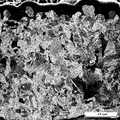
- 2 is a FIB-SIM image showing an example of a cross-sectional crystal structure of Example 1 after pre-annealing at 200 ° C. for 8 hours and after heating at 350 ° C. for 5 hours.
- 2 is a FIB-SIM image showing an example of a cross-sectional crystal structure of Comparative Sample 1 after heating at 350 ° C. for 5 hours.
- the surface-treated copper foil according to the present invention is provided with a surface treatment layer containing zinc (referred to as a zinc adhesion layer in the present embodiment) on both sides of the copper foil, and after the zinc adhesion layer is formed, pre-annealing treatment is performed.
- a surface treatment layer containing zinc referred to as a zinc adhesion layer in the present embodiment
- pre-annealing treatment is performed.
- the high temperature refers to a temperature higher than the temperature at which copper recrystallization occurs, and mainly refers to a temperature in the range of about 300 ° C. to 400 ° C.
- the long time means a time exceeding 1 hour and mainly means a time of 5 hours or more.
- the surface-treated copper foil will be described as an example in which the surface-treated copper foil is used as a negative electrode current collector of a non-aqueous secondary battery such as a lithium ion secondary battery, but the surface-treated copper according to the present invention is described.
- the foil can be used not only as a negative electrode current collector of a non-aqueous secondary battery such as the lithium ion secondary battery but also as a material for producing a printed wiring board.
- copper foil is demonstrated.
- the said zinc adhesion layer is provided on both surfaces of the copper foil which contains 100 ppm or more of 1 type, or 2 or more types of trace components chosen from carbon, sulfur, chlorine, and nitrogen in a total amount.
- copper foil means an untreated copper foil that has not been subjected to various treatments such as the above surface treatment
- surface treated copper foil means the zinc adhesion layer.
- the copper foil after various surface treatments is meant.
- the copper foil may be an electrolytic copper foil or a rolled copper foil, but it is easy to obtain a copper foil having fine crystal grains and excellent mechanical properties with high tensile strength. From the viewpoint, an electrolytic copper foil is preferable.
- an electrolytic copper foil is preferable.
- description will be given mainly by taking an electrolytic copper foil as an example, but in the following, when simply described as “copper foil", the copper foil includes not only “electrolytic copper foil” but also "rolled copper foil” Shall be.
- the copper foil contains one or more trace components selected from carbon, sulfur, chlorine and nitrogen in a total amount of 100 ppm or more.
- trace components selected from carbon, sulfur, chlorine and nitrogen in a total amount of 100 ppm or more.
- the copper foil used in the present invention contains 100 ppm or more of the trace components in total, and contains 20 ppm to 470 ppm of carbon, 5 ppm to 600 ppm of sulfur, 15 ppm to 600 ppm of chlorine, and 5 ppm to 600 ppm of nitrogen. It is preferable to do.
- the average crystal grain size of the copper foil is 1.0 ⁇ m or less
- the normal tensile strength is 50 kgf / mm 2 or more
- the normal elongation is 3%.
- a copper foil excellent in mechanical strength of ⁇ 15% can be obtained.
- each trace component when the content of each trace component is less than the lower limit value, for example, it is difficult to obtain a very fine crystal structure having an average crystal grain size of 1.0 ⁇ m or less, and copper having a higher tensile strength. A foil cannot be obtained, which is not preferable.
- content of each trace component in the said copper foil exceeds an upper limit, it is unpreferable from the following viewpoints. If the carbon content exceeds 470 ppm, the graphite becomes coarse and cracks are likely to occur, which is not preferable. When the sulfur content exceeds 600 ppm, the tensile strength of the copper foil is increased, but the elongation rate is lowered and embrittlement is not preferable.
- the chlorine content exceeds 600 ppm
- the deposited surface becomes rough in the case of an electrolytic copper foil.
- the negative electrode active material or the like it is difficult to adhere the negative electrode active material or the like to the surface without unevenness, and the amount of volume change when charging / discharging is repeated becomes non-uniform in a plane, which is not preferable.
- the nitrogen content exceeds 180 ppm
- the nitrogen compound becomes excessive, the effect of refining the precipitate structure of the copper foil is saturated, and the significance of increasing the nitrogen content is lost, which is not preferable.
- the unit of “ppm” used to represent the content of the trace component in the copper foil is synonymous with “mg / kg”, and that the trace component contains 100 ppm or more in total. It means that the total amount of the trace components contained per 1 kg of the copper foil is 100 mg or more.
- the average crystal grain size of the copper crystal grains constituting the crystal structure of the copper foil is preferably 1.0 ⁇ m or less, and more preferably 0.8 ⁇ m or less.
- the average crystal grain size exceeds 1.0 ⁇ m, it is difficult to maintain a tensile strength at a level required as a negative electrode current collector of a non-aqueous secondary battery such as a lithium ion secondary battery.
- the copper crystal grains constituting the copper foil are fine and uniform. Due to the uniform crystal grains, the grain boundaries are evenly distributed in the copper foil, and the load applied to the copper foil is dispersed without being biased to specific crystal grains, and the mechanical strength is high.
- the average crystal grain size refers to the average crystal grain size in the normal state of the copper foil, and can be determined based on the crystal grain size appearing in the cross section when the cross section of the copper foil is observed. .
- Normal tensile strength The normal tensile strength of the copper foil is preferably 50 kgf / mm 2 or more.
- “normal state” refers to a state managed at normal temperature or a state before heat treatment.
- the normal tensile strength of the copper foil itself is a higher value, and the surface-treated copper foil after being subjected to heat treatment regardless of the value of the normal tensile strength.
- the tensile strength of is preferably a higher value.
- the thickness of the copper foil is not particularly limited. What is necessary is just to employ
- the thickness of the copper foil is within a range of 5 ⁇ m to 35 ⁇ m (gauge thickness). And often.
- the thickness of the copper foil is often in the range of 5 ⁇ m to 120 ⁇ m (gauge thickness).
- the surface-treated copper foil according to the present invention is a thin copper foil of 5 ⁇ m to 35 ⁇ m, it has a tensile strength of a level required in the market as a negative electrode current collector of a lithium ion secondary battery.
- the surface-treated copper foil of the present invention is provided with a zinc adhesion layer containing 20 mg / m 2 to 1000 mg / m 2 of zinc per side on both sides of the copper foil.
- Zinc in the zinc adhesion layer provided on both sides of the copper foil diffuses into the copper foil with the passage of time and reacts with the trace components in the crystal structure. This zinc and the compound of the trace component are precipitated at the crystal grain boundary, and when the copper foil is heated, the growth of the crystal grain is prevented and the effect of suppressing the coarsening of the crystal grain is exhibited.
- the present invention after forming a zinc adhesion layer on both sides of the copper foil, by applying a pre-annealing treatment described later, zinc is not only the surface layer portion of the copper foil but also its inside ( Can be diffused to the center). Therefore, according to the present invention, even if the surface-treated copper foil is subjected to a heat treatment for a longer time at a high temperature in the subsequent use process, a fine crystal structure can be maintained even after the heat treatment. It can suppress and it can suppress that the tensile strength of the said copper foil falls.
- the amount of zinc deposited is preferably 25 mg / m 2 or more, and more preferably 50 mg / m 2 or more.
- the adhesion amount of zinc is preferably 500 mg / m 2 or less, more preferably 300 mg / m 2 or less, and further preferably 200 mg / m 2 or less.
- the total adhesion amount of zinc to the copper foil is within the range of 40 mg / m 2 to 2000 mg / m 2 .
- the total adhesion amount of the zinc is preferably 50 mg / m 2 or more, more preferably 100 mg / m 2 or more, from the same viewpoint as described above.
- the upper limit is more preferably is preferably 1000 mg / m 2 or less, 600 mg / m 2 or less.
- the zinc adhesion amount is the zinc adhesion amount (converted amount) per unit area when it is assumed that the surface of the copper foil is completely flat.
- the zinc adhesion layer can be a zinc layer made of zinc, or in addition to zinc, a zinc alloy layer containing copper and / or a metal element whose diffusion rate in copper is faster than zinc.
- a zinc alloy layer containing copper and / or a metal element whose diffusion rate in copper is faster than zinc.
- a metal element (hereinafter referred to as “foreign metal element”) having a diffusion rate in copper that is faster than that of zinc at a temperature of 300 ° C. or higher.
- foreign metal element a metal element having a diffusion rate in copper that is faster than that of zinc at a temperature of 300 ° C. or higher.
- the zinc adhesion layer may be a zinc-based composite layer in which a zinc layer and a dissimilar metal layer containing at least one of the dissimilar metal elements or two or more of them are stacked.
- the stacking order of the zinc layer and the dissimilar metal layer is not limited, and the zinc layer and the dissimilar metal layer may be sequentially stacked on the surface of the copper foil, or the dissimilar metal layer and zinc may be stacked on the surface of the copper foil. You may laminate
- the zinc adhesion layer contain the different metal element together with zinc, the different metal element can be diffused together with zinc in the copper foil. Since the diffusion rate of different metal elements is faster than that of zinc, these different metal elements reach deeper positions faster than zinc in the thickness direction of the copper foil. In addition, these different metal elements react with the above-mentioned trace components in the same manner as zinc to form a compound and suppress the coarsening of copper crystal grains.
- the zinc adhesion layer contains a dissimilar metal element together with zinc, even when heat treatment is performed at a high temperature for a longer time, the copper crystal grains become coarse in almost the entire thickness direction of the copper foil. Can be suppressed more effectively.
- Zinc refers to zinc having a purity of 99% or more.
- a zinc alloy refers to a mixture, solid solution, eutectic, compound, or the like of zinc and other elements.
- the zinc adhesion layer is a zinc alloy layer or a zinc-based composite layer
- the amount of the surface treatment so that the amount of deposition of tin is 1mg / m 2 ⁇ 200mg / m 2 per the above one side is preferably subjected.
- the zinc content ratio calculated by ⁇ [zinc adhesion amount] / [zinc-tin alloy adhesion amount] ⁇ ⁇ 100 is 30% by mass or more.
- zinc adhesion layers can be formed using, for example, a rust preventive agent containing zinc or zinc-tin, and function as a rust preventive layer.
- the surface-treated copper foil according to the present invention may have other surface treatment layers such as a roughening treatment layer, a chromate treatment layer, and an organic agent treatment layer as necessary. Can be optionally provided.
- the surface-treated copper foil when used as a negative electrode current collector of a lithium ion secondary battery by providing a roughened layer, the adhesion between the surface of the surface-treated copper foil and the negative electrode active material is improved. be able to.
- the chromate treatment layer and / or the organic agent treatment layer it is possible to suppress the copper foil surface from being oxidized by these layers together with the zinc adhesion layer. Moreover, the adhesiveness with the negative electrode active material etc. of the said lithium ion secondary battery can be made still better.
- the organic agent treatment layer include a silane coupling agent treatment layer and an organic rust prevention treatment layer.
- the surface-treated copper foil according to the present invention can be obtained by subjecting both surfaces of the copper foil to the above-mentioned surface treatment, followed by pre-annealing treatment that is heated in a temperature range of 200 ° C to 280 ° C.
- pre-annealing treatment zinc can be diffused into the copper foil in a state where recrystallization of copper is suppressed.
- the surface treatment copper foil is loaded with heat higher than the temperature at which copper recrystallization occurs, the above-mentioned compounds precipitated at the grain boundaries prevent the growth of crystal grains and the crystal grains become coarse. The effect which suppresses this can be exhibited.
- the pre-annealing process will be described later.
- the copper foil after the above surface treatment and before the pre-annealing treatment may be referred to as “surface-treated copper foil”.
- the surface-treated copper foil according to the present invention has the tensile strength after heating at 350 ° C. for 5 hours in an inert gas atmosphere by subjecting the surface-treated copper foil to the pre-annealing treatment. Is 45 kgf / mm 2 or more, and the tensile strength after the heat treatment is 50 kg / mm by adjusting the pre-annealing conditions to appropriate conditions according to the amount of copper foil and zinc (and tin) attached. 2 or more. In the present invention, it is particularly preferable that the tensile strength after heating at 350 ° C. for 5 hours is 50 kgf / mm 2 or more by adjusting the conditions of the pre-annealing treatment.
- the surface-treated copper foil according to the present invention preferably has a tensile strength maintenance rate within a range of 90% to 100% after heating at 350 ° C. for 5 hours with respect to the tensile strength in a normal state. More preferably, the maintenance ratio of the tensile strength is in the range of 95% to 100%. According to the present invention, by performing the pre-annealing treatment, it is possible to improve the maintenance ratio of the tensile strength after the heat treatment as compared with the case where the pre-annealing treatment is not performed.
- the copper foil which contains 100 ppm or more of 1 type, or 2 or more types of trace components chosen from carbon, sulfur, chlorine, and nitrogen in a total amount is prepared.
- the content of each trace component is preferably within the above-described range.
- the average crystal grain size of copper constituting the copper foil is preferably 1.0 ⁇ m or less, and the average crystal grain size is more preferably 0.8 ⁇ m or less as described above.
- a copper foil satisfying such conditions can be obtained, its production method is not limited, but by adjusting various additives in the electrolyte, a copper foil satisfying the above conditions can be obtained. From the viewpoint of ease, it is preferable to produce a copper foil by an electrolytic method.
- the roughening treatment layer has an arbitrary layer structure, and there is no particular limitation on the roughening treatment method and the roughening treatment conditions.
- pretreatment such as pickling treatment of the copper foil surface may be performed.
- the roughening treatment method and the roughening treatment conditions are not limited to this, and a conventionally known method can be appropriately adopted according to the surface characteristics required for the copper foil. That's fine.
- Zinc adhesion treatment a surface treatment (hereinafter referred to as “zinc adhesion treatment”) is performed on the surface of the copper foil using a surface treatment agent containing zinc to form a zinc adhesion layer containing zinc.
- a zinc adhesion layer can be formed in the surface of copper foil so that the adhesion amount of zinc may become in the said range.
- an electrochemical method such as electrolytic plating or electroless plating, or a physical vapor deposition method such as sputtering vapor deposition or chemical vapor reaction can be used.
- an electrochemical method such as electrolytic plating or electroless plating, or a physical vapor deposition method such as sputtering vapor deposition or chemical vapor reaction can be used.
- metal elements other than zinc may be contained in the surface treating agent, and the point that tin is preferable as the other metal elements is also as described above.
- Electrolytic plating method When the zinc adhesion treatment is performed on the surface of the copper foil by the electrolytic plating method, a zinc pyrophosphate zinc plating bath, a zinc cyanide plating bath, a zinc sulfate plating bath, or the like can be used.
- a zinc pyrophosphate plating bath specifically, a bath composition having a zinc concentration of 5 g / l to 30 g / l, a potassium pyrophosphate concentration of 50 g / l to 500 g / l, and a pH of 9 to pH 12 is employed.
- the copper foil itself is polarized to the cathode and electrolyzed under the conditions of a current density of 0.3 A / dm 2 to 10 A / dm 2 A, thereby attaching zinc to the copper foil surface.
- a layer can be formed.
- a chromate treatment may be optionally applied to the surface of the zinc adhesion layer.
- the chromate treatment includes electrolytic chromate treatment and immersion chromate treatment, and any method may be used. However, in consideration of the thickness variation of the chromate film, the stability of the adhesion amount, etc., it is preferable to employ electrolytic chromate treatment. Electrolytic conditions in the case of electrolytic chromate treatment are not particularly limited, and appropriate conditions can be adopted as appropriate.
- Organic agent treatment Moreover, you may perform an organic agent treatment with respect to the surface of a zinc adhesion layer.
- Examples of the organic agent treatment include silane coupling agent treatment and organic rust prevention treatment.
- Silane coupling agent treatment is not indispensable, considering the adhesiveness with the negative electrode active material of the insulating resin base material or lithium ion secondary battery required for the copper foil. Therefore, appropriate conditions and methods can be adopted as appropriate.
- Organic rust prevention treatment In order to further improve the rust prevention effect, when organic rust prevention treatment is performed, for example, benzotriazoles such as methylbenzotriazole (tolyltriazole), aminobenzotriazole, carboxyl benzotriazole, benzotriazole Surface treatment can be performed using an organic agent such as. As other organic agents, aliphatic carboxylic acids, alkylamines, benzoic acids, imidazoles, triazine thiols and the like may be used. The organic rust prevention treatment is not particularly limited, and appropriate conditions and methods can be appropriately employed.
- Drying step When the various surface treatments are completed on the copper foil, the drying step is performed, and the copper foil in a wet state in the various surface treatment steps is dried. Drying conditions are not particularly limited. However, when the organic agent treatment is performed, the silane coupling agent and / or organic rust preventive agent adhering to the copper foil surface is prevented from being thermally decomposed, and these agents are fixed on the copper foil surface in good condition. What is necessary is just to employ
- the pre-annealing process diffuses zinc from the zinc adhesion layer side into the copper foil by heat-treating the copper foil that has undergone the processes up to the drying process in a temperature range of 200 ° C. to 280 ° C. This is a step of obtaining the surface-treated copper foil.
- the copper foil is less likely to be coarsened even when heated in a temperature range of 200 ° C. to 280 ° C.
- the zinc is contained in the copper foil at a rate commensurate with industrial production efficiency as compared with the case where the copper foil is stored at room temperature.
- the zinc distribution in the copper foil can be made uniform.
- processing time the time for pre-annealing (hereinafter referred to as “processing time”) will be described.
- the amount of zinc diffused into the copper foil can be increased compared with the case where it is stored at room temperature, and even after heat treatment at high temperature. It is possible to suppress a decrease in tensile strength.
- the treatment time is preferably 2 hours or more and 25 hours or less.
- the said processing time is 8 hours or more and 25 hours or less from a viewpoint of diffusing zinc fully inside a copper foil, and making more uniform the distribution of zinc in copper foil.
- the treatment time is less than 2 hours, the amount of zinc diffusion into the copper foil is small, and if high-temperature heat treatment is performed for a long time, the crystal grains may be coarsened inside the copper foil. In some cases, the decrease in tensile strength cannot be sufficiently suppressed.
- the pre-annealing time is 25 hours or longer, the effect of suppressing the coarsening of the copper crystal grains is saturated even if the pre-annealing treatment is further performed. Moreover, the cost etc. concerning heat processing also increase. Therefore, from these viewpoints, the pre-annealing time is preferably within 25 hours.
- the pre-annealing conditions are the optimum heating temperature and / or suitable for the diffusion of zinc, depending on the crystal structure of the copper foil, the content of trace components in the copper foil, the amount of zinc attached to the copper foil, etc. Time is different. Accordingly, it is preferable to appropriately set appropriate pre-annealing conditions in the temperature and time within the above range according to these.
- the negative electrode current collector according to the present invention is characterized by using the surface-treated copper foil according to the present invention described above, and in a non-aqueous secondary battery such as a lithium ion secondary battery, is in contact with the negative electrode mixture inside the battery. It can be used as a current collector.
- the current collector according to the present invention is not particularly limited except that the surface-treated copper foil is used. Since the current collector according to the present invention uses the surface-treated copper foil, it has excellent mechanical properties such as tensile strength.
- the non-aqueous secondary battery is a general term for secondary batteries using an electrolyte other than an aqueous solution, and a secondary battery using an organic electrolyte, a polymer gel electrolyte, a solid electrolyte, a polymer electrolyte, a molten salt electrolyte, or the like.
- the negative electrode material according to the present invention is not particularly limited as long as the current collector is used.
- the negative electrode mixture layer can include, for example, a negative electrode active material, a conductive agent, and a binder.
- the surface-treated copper foil according to the present invention has a higher effect of suppressing a decrease in tensile strength than the case where the pre-annealing treatment is not performed, and the retention rate of the tensile strength after the heat treatment is increased.
- a tensile strength 45 kgf / mm 2 or more, preferably 50 kgf / mm 2 or more even after heating at 350 ° C. for 5 hours in an inert gas atmosphere. For this reason, by repeating the charge / discharge cycle in a lithium ion secondary battery or the like, even when a stress is repeatedly applied to the current collector, there is little risk of deformation such as wrinkles or breakage in the current collector.
- the electrical characteristics of the secondary battery can be maintained. Moreover, when manufacturing the negative electrode material of a lithium ion secondary battery, high temperature heat
- Example 1 the copper foil according to the present invention was manufactured and compared with Comparative Example 1 described later. Hereinafter, it will be described in the order of steps.
- an electrolytic copper foil having a total amount of the above trace elements in the copper foil of 100 ppm or more (carbon 44 ppm, sulfur 14 ppm, chlorine 54 ppm, nitrogen 11 ppm, average crystal grain size 0.64 ⁇ m) was prepared.
- an electrolytic copper foil having a thickness of 12 ⁇ m and not subjected to surface treatment was prepared for use in the manufacture of a VLP copper foil manufactured by Mitsui Kinzoku Co., Ltd.
- Roughening treatment step The copper foil is immersed in a copper plating solution having a free sulfuric acid concentration of 200 g / l, a copper concentration of 8 g / l, and a liquid temperature of 35 ° C. Electrolysis was performed under a burn copper plating condition with a density of 25 A / dm 2 , and fine copper particles were deposited on the cathode side surface of the copper foil. Next, in order to prevent the fine copper particles from falling off, the copper foil itself is polarized to the cathode in a copper plating solution having a free sulfuric acid concentration of 110 g / l, a copper concentration of 70 g / l, and a liquid temperature of 50 ° C. Electrolysis was performed under smooth plating conditions with a density of 25 A / dm 2 to complete the roughening treatment on the cathode side.
- Zinc adhesion treatment process A zinc adhesion layer made of a zinc-tin alloy was formed on both surfaces of the copper foil using a surface treatment agent containing zinc and tin on both surfaces of the copper foil after the roughening treatment. First, the formation method of a zinc adhesion layer is demonstrated.
- a zinc-tin alloy layer was formed as a zinc adhesion layer on both sides of the copper foil using a zinc pyrophosphate-tin plating bath.
- the zinc pyrophosphate-tin plating bath composition was such that the zinc concentration was 1 g / l to 6 g / l, the tin concentration was 1 g / l to 6 g / l, the potassium pyrophosphate concentration was 100 g / l, and the pH was 10.6.
- the liquid temperature is set to 30 ° C.
- the copper foil itself is polarized to the cathode, and the current density and electrolysis time are appropriately adjusted, so that the zinc adheres to one side of the copper foil.
- a copper foil having an amount of 50 mg / m 2 and an adhesion amount of tin of 5 mg / m 2 was obtained.
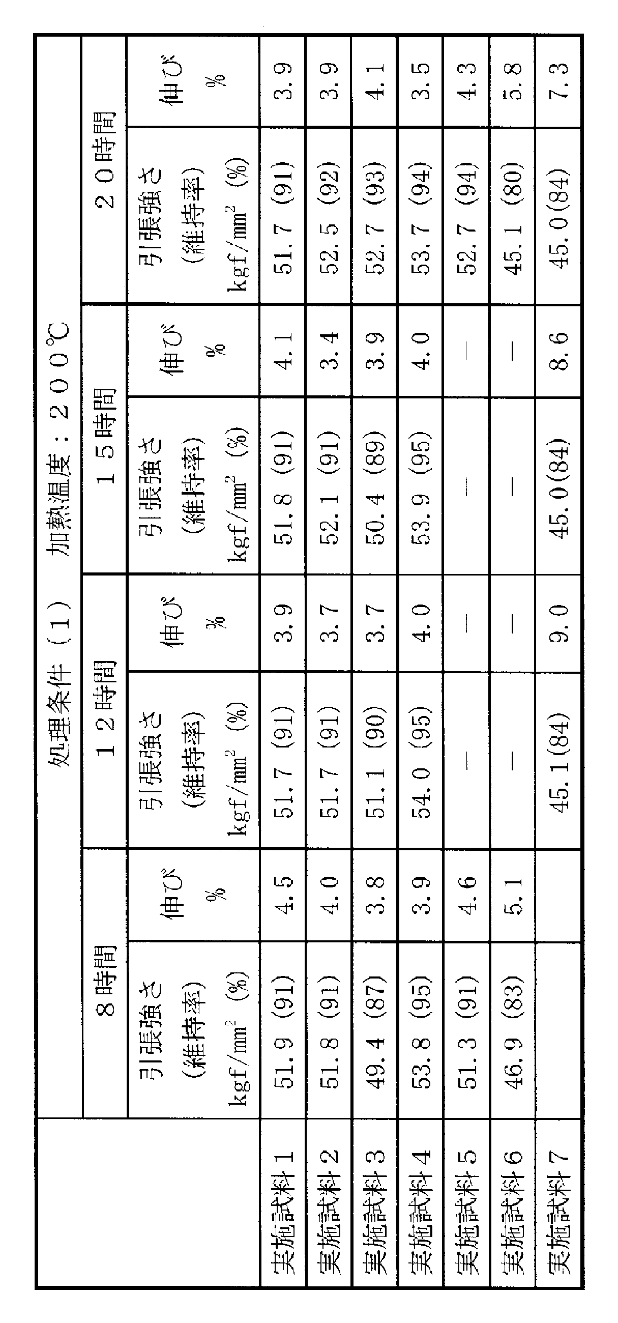
- Pre-annealing treatment step Next, pre-annealing treatment was performed on the sample 1 under the conditions shown in Table 1, and this was designated as an implementation sample 1. However, in the pre-annealing treatment, each sample was put in an oven and the internal temperature was raised at 5 ° C./min. In Table 1, the sample 1 was heated under the corresponding processing conditions. In Table 1, the column labeled “ ⁇ ” means that the pre-annealing process was performed on the sample with the number indicated in parentheses in the column under the conditions (temperature, processing time).
- Example 2 sample 2 was prepared in the same manner as in Example 1 except that the amount of tin deposited on one side was 15 mg / m 2, and then pre-annealing was performed under the conditions shown in Table 1. Sample 2 was obtained.
- Example 3 sample 3 was prepared in the same manner as in Example 1 except that the amount of tin deposited on one side was 30 mg / m 2, and then pre-annealed under the conditions shown in Table 1. It was set to 3.
- Example 4 Sample 4 was prepared in the same manner as in Example 1 except that the adhesion amount per one side of tin was 15 mg / m 2 and the total adhesion amount of zinc was 100 mg / m 2. A pre-annealing treatment was performed under the conditions shown in the following to obtain an implementation sample 4.
- Example 5 Sample 5 was prepared in the same manner as in Example 1 except that the adhesion amount per one side of tin was 15 mg / m 2 and the total adhesion amount of zinc was 150 mg / m 2. A pre-annealing treatment was performed under the conditions shown in the following to obtain an implementation sample 5.
- Example 6 In Example 6, another copper foil according to the present invention was manufactured as follows. Hereinafter, it will be described in the order of steps.
- Example 6 an electrolytic copper foil produced under the following conditions was used. First, an electrolytic solution (50 ° C.) containing copper ions at a concentration of 80 g / l, sulfuric acid at a concentration of 250 g / l, chlorine ions at a concentration of 2.7 ppm, and gelatin at a concentration of 2 ppm is used as the sulfuric acid-based copper electrolytic solution. Electrolysis was performed at a current density of 50 A / dm 2 to obtain an electrolytic copper foil having a thickness of 12 ⁇ m. The content of trace components in the electrolytic copper foil was 49 ppm carbon, 26 ppm sulfur, 24 ppm chlorine, 11 ppm nitrogen, and the average crystal grain size was 0.58 ⁇ m.
- Zinc adhesion step The same as in Example 1 except that the electrolytic copper foil after the above roughening treatment had a tin adhesion amount of 25 mg / m 2 and a zinc adhesion amount of 150 mg / m 2 per side.
- Sample 6 was prepared by forming a zinc adhesion layer on both sides of the copper foil. Then, in the same manner as in Example 1, pre-annealing treatment was performed under the conditions shown in Table 1, and the sample after each pre-annealing treatment was designated as Working Sample 6.
- Example 7 a surface-treated copper foil was produced in the same manner as in Example 1 except that a zinc layer was formed as the zinc adhesion layer.
- the zinc layer was formed using a zinc pyrophosphate plating bath.
- the zinc pyrophosphate plating bath was electrolyzed in the same manner as in Example 1 except that a zinc composition having a zinc concentration of 6 g / l, a potassium pyrophosphate concentration of 125 g / l, and a pH of 10.5 was employed.
- a copper foil having a zinc adhesion amount of 50 mg / m 2 per side was obtained, and this was designated as Sample 7.
- pre-annealing treatment was performed under the conditions shown in Table 1, and a sample after each pre-annealing was taken as an execution sample 7.
- samples were prepared in the same manner as in Examples 1 to 7 except that the pre-annealing treatment was not performed, and they were designated as Comparative Sample 1 to Comparative Sample 7, respectively.
- Table 2 shows the total amount of tin and zinc deposited on each sample and the type of copper foil.
- Table 2 shows the normal tensile strength of each copper foil (A or B) measured by the method described later.
- type A of copper foil refers to the electrolytic copper foil used in Examples 1 to 5 and Example 7
- type B of copper foil refers to the method described in Example 6. It refers to the produced electrolytic copper foil.
- the conditions of the scanning electron microscope at the time of observation were an acceleration voltage: 20 kV, an aperture diameter: 60 mm, a high current mode, and a sample angle: 70 °.
- the observation magnification, the measurement region, and the step size were measured by changing the conditions as appropriate according to the size of the crystal grains.
- Tables 3 to 7 show the tensile strengths of the respective samples and comparative samples after heat treatment at 350 ° C. for 5 hours.
- Table 7 shows the tensile strengths of Comparative Sample 5 and Comparative Sample 6 after heating at 350 ° C. for 1 hour.
- surface shows the maintenance rate of the tensile strength after the heat processing of each sample with respect to normal state tensile strength in percentage.
- the working sample 1 to the working sample 7 according to the present invention have a tensile strength of 45 kgf after heating at 350 ° C. for 5 hours regardless of the pre-annealing treatment conditions. / Mm 2 or more, and maintained a tensile strength of 79% to 102% of the normal tensile strength. Also, by adjusting the zinc adhesion amount, tin adhesion amount, etc. according to the content of the trace component of the copper foil, etc., by adopting preferable pre-annealing treatment conditions, 50 kgf even after heating at 350 ° C. for 5 hours. It was confirmed that the tensile strength of / mm 2 or more can be maintained, and the rate of decrease in tensile strength can be suppressed within 10%, more preferably within 5%.
- the zinc adhesion layer is a zinc-tin alloy layer, so that the zinc adhesion layer is more heat-treated than when the zinc adhesion layer is a zinc layer not containing tin. It was confirmed that the value of tensile strength was high and the maintenance rate was also improved.
- FIGS. 1 and 2 are FIB-SIM images showing the crystal structures of Example 1 and Comparative Sample 1 after heating at 350 ° C. for 5 hours, respectively.
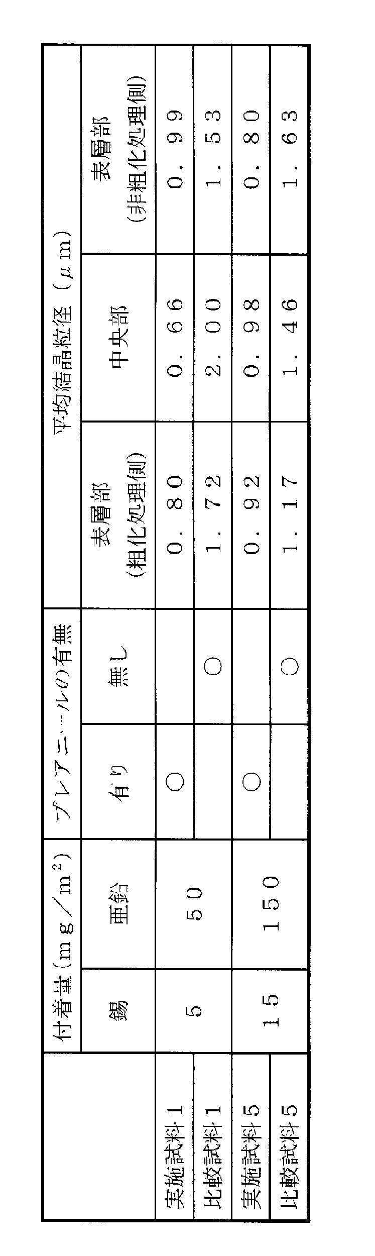
- Table 8 shows the average crystal grain size values of Example 1, Example 5, Comparative Sample 1 and Comparative Sample 5 after heating at 350 ° C. for 5 hours.
- the working sample 1 and the working sample 5 are pre-annealed (heated at 200 ° C. for 8 hours) before being heated at 350 ° C. for 5 hours. As shown in FIGS.
- the crystal structure of the working sample 1 is fine as a whole as compared with the crystal structure of the comparative sample 1.
- the working sample 1 and the working sample 5 have an average crystal grain size of 1.0 ⁇ m or less in any of the surface layer portion and the central portion of the copper foil, and are heated at 350 ° C. for 5 hours. It can be confirmed that a fine crystal structure is maintained throughout the thickness direction of the copper foil.
- the comparative sample 1 and the comparative sample 5 are heated at 350 ° C. for 5 hours, the average crystal grain size exceeds 1.0 ⁇ m in any region, and the crystal grains in the central portion of the copper foil are particularly coarse. It was confirmed that the tendency was high.
- zinc (and dissimilar metal elements) can be diffused not only to the surface layer portion of the copper foil but also to the center portion of the copper foil. It was confirmed that coarsening of copper crystal grains can be suppressed even when loaded.
- the surface copper foil according to the present invention can be easily manufactured by subjecting the surface of the copper foil to the surface treatment and then the pre-annealing treatment, and is subjected to a heat treatment for a long time at a high temperature. Even after being applied, it is possible to provide a copper foil with little decrease in tensile strength. Therefore, it can be suitably used for applications exposed to a high-temperature atmosphere during production, and can be particularly preferably used as a material for producing a negative electrode current collector of a non-aqueous secondary battery such as a lithium ion secondary battery and a printed wiring board.
Landscapes
- Chemical & Material Sciences (AREA)
- Engineering & Computer Science (AREA)
- Materials Engineering (AREA)
- Chemical Kinetics & Catalysis (AREA)
- Metallurgy (AREA)
- Organic Chemistry (AREA)
- Electrochemistry (AREA)
- Mechanical Engineering (AREA)
- General Chemical & Material Sciences (AREA)
- Crystallography & Structural Chemistry (AREA)
- Manufacturing & Machinery (AREA)
- Microelectronics & Electronic Packaging (AREA)
- Physics & Mathematics (AREA)
- Thermal Sciences (AREA)
- Cell Electrode Carriers And Collectors (AREA)
- Electroplating Methods And Accessories (AREA)
- Solid-Phase Diffusion Into Metallic Material Surfaces (AREA)
- Other Surface Treatments For Metallic Materials (AREA)
Abstract
本件発明の課題は、高温の熱処理が長時間施された場合でも、引張強さの低下の少ない表面処理銅箔、表面処理銅箔の製造方法、当該表面処理銅箔を用いた集電体及び非水系二次電池の負極材を提供することにある。 上記課題を解決するため炭素、硫黄、塩素及び窒素から選ばれる1種又は2種以上の微量成分をその総量で100ppm以上含む銅箔の両面に、片面当たり20mg/m2~1000mg/m2の亜鉛を含む表面処理層を備えた表面処理銅箔であって、200℃~280℃の温度範囲で加熱するプレアニール処理が施されたことを特徴とする表面処理銅箔を提供する。
Description
本件発明は、表面処理銅箔、表面処理銅箔の製造方法、負極集電体及び非水系二次電池の負極材に関する。特に、高温で長時間加熱された場合でも、引張強さの低下が少ないリチウムイオン二次電池等の負極集電体用途に用いられる表面処理銅箔、その製造方法、当該表面処理銅箔を用いた負極集電体及び負極材に関する。
従来より、銅箔はプリント配線板をはじめとして種々の電子部品の回路形成材料として使用されている。また、近年では、銅箔はこれらの回路形成材料に限らず、リチウムイオン二次電池等の非水系二次電池の負極集電体としても用いられている。
一般に、リチウムイオン二次電池の負極材は、導電性材料からなる集電体の表面に負極活物質と、導電材と、結着剤(バインダー)等を含む負極合剤層を備えて構成される。リチウムイオン二次電池の充放電時において、負極活物質がリチウムを吸蔵・放出すると、これに伴い負極合剤層が膨張・収縮する。負極合剤層は集電体の表面に密着されているため、リチウムイオン二次電池の充放電サイクルを繰り返すことにより、負極合剤層と集電体との間には繰返し応力が加わる。このため、集電体の引張強さが低いと、集電体は負極合剤の体積変化により、伸張して皺などの変形を生じたり、破断する恐れがある。集電体が伸張して皺などの変形を生じた場合、正極と負極との間で短絡が生じたり、正極と負極との間の距離が変化して均一な電極反応が阻害され、充放電サイクル耐久性が低下する恐れがある。また、集電体が破断した場合は、単位体積当たりの容量が減少し、リチウムイオン二次電池の電池的特性が低下する。このため、集電体として銅箔を用いる場合、当該銅箔は高い引張強さを有することが求められる。
ところで、負極材を製造する工程では、集電体の表面に負極合剤層を形成する際に、高温の熱が集電体に負荷される。一般的な銅箔の場合、高温の熱が負荷されると、銅の再結晶化により結晶粒が粗大化し、引張強さ等の機械的強度が低下する。このため、集電体用途に用いる銅箔は、高温の熱処理が施された後も高い引張強さを維持することが求められる。このような銅箔として、例えば、特許文献1及び特許文献2には、350℃で60分間加熱した後であっても40kgf/mm2以上、400℃で60分間加熱した後についても35kgf/mm2以上の引張強さを維持することのできる表面処理銅箔が開示されている。
しかしながら、リチウムイオン二次電池の負極材を製造する際には、集電体に対して350℃~400℃の温度範囲で1時間を超える加熱が行われる場合がある。この場合、上記特許文献1又は特許文献2に開示の表面処理銅箔では引張強さが低下し、加熱時間によっては、十分なレベルの引張強さを維持することができない場合があった。
従って、本件発明の課題は、高温の熱処理が長時間施された場合でも、引張強さの低下の少ない表面処理銅箔、表面処理銅箔の製造方法、当該表面処理銅箔を用いた集電体及び非水系二次電池の負極材を提供することにある。
本発明者等は、鋭意研究を行った結果、以下の技術的思想を採用することにより、高温の熱処理が長時間施された場合でも、引張強さの低下の少ない表面処理銅箔に想到した。
本件発明に係る表面処理銅箔は、炭素、硫黄、塩素及び窒素から選ばれる1種又は2種以上の微量成分をその総量で100ppm以上含む銅箔の両面に、片面当たり20mg/m2~1000mg/m2の亜鉛を含む表面処理層を備えた表面処理銅箔であって、200℃~280℃の温度範囲で加熱するプレアニール処理が施されたことを特徴とする。
本件発明に係る表面処理銅箔は、350℃で5時間加熱した後の引張強さが45kgf/mm2以上を示す。
本件発明に係る表面処理銅箔において、前記表面処理層は亜鉛以外に、銅及び/又は銅中の拡散速度が亜鉛よりも速い金属元素を含むことが好ましい。
本件発明に係る表面処理銅箔において、前記金属元素は錫であることが好ましい。
本件発明に係る表面処理銅箔において、前記表面処理層には片面当たり1mg/m2~200mg/m2の錫が含まれることが好ましい。
本件発明に係る表面処理銅箔において、前記銅箔を構成する銅の平均結晶粒径が1.0μm以下であることが好ましい。
本件発明に係る表面処理銅箔において、前記銅箔の常態引張強さは50gf/mm2以上であることが好ましい。
本件発明に係る表面処理銅箔において、前記プレアニール処理では、前記温度範囲内の温度で2時間以上25時間以下加熱されることが好ましい。
本件発明に係る表面処理銅箔は、炭素、硫黄、塩素及び窒素から選ばれる1種又は2種以上の微量成分をその総量で100ppm以上含む銅箔の両面に、片面当たり20mg/m2~1000mg/m2の亜鉛を含む表面処理層を備えた表面処理銅箔であって、350℃で5時間加熱した後の引張強さが50kgf/mm2以上であることを特徴とする。
本件発明に係る表面処理銅箔の製造方法は、炭素、硫黄、塩素及び窒素から選ばれる1種又は2種以上の微量成分をその総量で100ppm以上含む銅箔の両面に、片面当たり20mg/m2~1000mg/m2の亜鉛を含む表面処理層を形成する表面処理工程と、表面処理工程の後、200℃~280℃の温度範囲で加熱するプレアニール処理工程と、を備えることを特徴とする。
本件発明に係る表面処理銅箔の製造方法では、前記プレアニール処理工程における加熱時間が2時間以上25時間以下であることが好ましい。
本件発明に係る負極集電体は、上記いずれかに記載の表面処理銅箔を用いたことを特徴とする。
本件発明に係る非水系二次電池の負極材は、上記負極集電体を用いたことを特徴とする。
本件発明に係る表面処理銅箔は、銅箔の両面に亜鉛を含む表面処理層を形成し、上記プレアニール処理を施すことにより、簡易に製造することができ、且つ、高温の熱処理が長時間施された後であっても、引張強さの低下の少ない銅箔を提供することができる。
以下、本件発明に係る表面処理銅箔、表面処理銅箔の製造方法、負極集電体及び非水系二次電池の負極材の実施の形態を順に説明する。
1.表面処理銅箔
まず、本件発明に係る表面処理銅箔の実施の形態を説明する。本件発明に係る表面処理銅箔は、銅箔の両面に、亜鉛を含む表面処理層(本実施の形態では亜鉛付着層と称する。)を備え、当該亜鉛付着層が形成された後、プレアニール処理を施すことにより、高温の熱処理が長時間施された後であっても、引張強さの低下を抑制できるようにしたものである。なお、本件明細書において高温とは、銅の再結晶化が生じる温度以上の温度を指し、主として300℃~400℃程度の範囲内の温度を指す。また、長時間とは1時間を超える時間を指し、主として5時間以上の時間を意味するものとする。以下、本実施の形態では、当該表面処理銅箔をリチウムイオン二次電池等の非水系二次電池の負極集電体として用いる場合を例に挙げて説明するが、本件発明に係る表面処理銅箔は、当該リチウムイオン二次電池等の非水系二次電池の負極集電体に限らず、プリント配線板の製造材料として用いることができるのは勿論である。
まず、本件発明に係る表面処理銅箔の実施の形態を説明する。本件発明に係る表面処理銅箔は、銅箔の両面に、亜鉛を含む表面処理層(本実施の形態では亜鉛付着層と称する。)を備え、当該亜鉛付着層が形成された後、プレアニール処理を施すことにより、高温の熱処理が長時間施された後であっても、引張強さの低下を抑制できるようにしたものである。なお、本件明細書において高温とは、銅の再結晶化が生じる温度以上の温度を指し、主として300℃~400℃程度の範囲内の温度を指す。また、長時間とは1時間を超える時間を指し、主として5時間以上の時間を意味するものとする。以下、本実施の形態では、当該表面処理銅箔をリチウムイオン二次電池等の非水系二次電池の負極集電体として用いる場合を例に挙げて説明するが、本件発明に係る表面処理銅箔は、当該リチウムイオン二次電池等の非水系二次電池の負極集電体に限らず、プリント配線板の製造材料として用いることができるのは勿論である。
(1)銅箔
まず、銅箔について説明する。本件発明では、炭素、硫黄、塩素及び窒素から選ばれる1種又は2種以上の微量成分を総量で100ppm以上含む銅箔の両面に上記亜鉛付着層が設けられる。
ここで、本件発明では、「銅箔」とは、上記表面処理等の各種処理が施されていない未処理の銅箔を意味するものとし、「表面処理銅箔」とは、上記亜鉛付着層を形成するための亜鉛付着処理、プレアニール処理の他、各種表面処理後の銅箔を意味するものとする。また、当該銅箔は、電解銅箔であっても、圧延銅箔であってもよいが、結晶粒が微細であり、引張強さの高い機械的特性に優れた銅箔が得られやすいという観点から、電解銅箔であることが好ましい。以下、主として、電解銅箔を例に挙げて説明するが、以下において、単に「銅箔」と記載した場合、当該銅箔には「電解銅箔」だけではなく、「圧延銅箔」が含まれるものとする。
まず、銅箔について説明する。本件発明では、炭素、硫黄、塩素及び窒素から選ばれる1種又は2種以上の微量成分を総量で100ppm以上含む銅箔の両面に上記亜鉛付着層が設けられる。
ここで、本件発明では、「銅箔」とは、上記表面処理等の各種処理が施されていない未処理の銅箔を意味するものとし、「表面処理銅箔」とは、上記亜鉛付着層を形成するための亜鉛付着処理、プレアニール処理の他、各種表面処理後の銅箔を意味するものとする。また、当該銅箔は、電解銅箔であっても、圧延銅箔であってもよいが、結晶粒が微細であり、引張強さの高い機械的特性に優れた銅箔が得られやすいという観点から、電解銅箔であることが好ましい。以下、主として、電解銅箔を例に挙げて説明するが、以下において、単に「銅箔」と記載した場合、当該銅箔には「電解銅箔」だけではなく、「圧延銅箔」が含まれるものとする。
微量成分: 本件発明において、上述したとおり、当該銅箔は炭素、硫黄、塩素及び窒素から選ばれる1種又は2種以上の微量成分を総量で100ppm以上含有する。これらの微量成分の含有量が総量で100ppm以上になると、当該銅箔を構成する銅の結晶組織(結晶粒)の微細化が容易になり、引張強さの高い機械的強度に優れた銅箔が得られやすくなるためである。
ここで、本件発明で用いる銅箔は、当該微量成分を総量で100ppm以上含有すると共に、炭素を20ppm~470ppm、硫黄を5ppm~600ppm、塩素を15ppm~600ppm、窒素を5ppm~600ppmの範囲で含有することが好ましい。銅箔の結晶組織内にこれらの微量成分を適正な量だけ含有させることにより、上記銅の結晶組織の微細化がより容易になり、引張強さのより高い機械的強度に優れた銅箔とすることができる。具体的には、各微量成分を上記範囲内で含有させることにより、当該銅箔の平均結晶粒径が1.0μm以下となり、常態引張強さが50kgf/mm2以上、常態伸び率が3%~15%という機械的強度に優れた銅箔とすることができる。
ここで、各微量成分の含有量が下限値未満の場合には、例えば、平均結晶粒径が1.0μm以下の極微細な結晶組織を得ることが困難であり、引張強さのより高い銅箔を得ることができず好ましくない。一方、当該銅箔内の各微量成分の含有量が上限値を超える場合、以下の観点から好ましくない。炭素含有量が470ppmを超える場合には、グラファイトが粗大化し、クラックが生じやすくなるため好ましくない。硫黄含有量が600ppmを超える場合には、当該銅箔の引張強さは高くなるが、伸び率が低下し、脆化するため好ましくない。塩素含有量が600ppmを超える場合には、電解銅箔の場合、その析出表面が粗くなる。その場合、その表面に負極活物質等をムラ無く密着させることが困難になり、充放電を繰り返した時の体積変化量が面内で不均一となり、局所的に破断することから好ましくない。さらに、窒素含有量が180ppmを超えると、窒素化合物が過剰となり、銅箔の析出組織の微細化効果が飽和して、窒素含有量を増加させる意義が没却するため好ましくない。
但し、本件発明において、当該銅箔中の微量成分の含有量を表すために用いた「ppm」という単位は「mg/kg」と同義であり、当該微量成分を総量で100ppm以上含むとは、当該銅箔1kg当たりに含まれる当該微量成分の総量が100mg以上であることを意味する。
但し、本件発明において、当該銅箔中の微量成分の含有量を表すために用いた「ppm」という単位は「mg/kg」と同義であり、当該微量成分を総量で100ppm以上含むとは、当該銅箔1kg当たりに含まれる当該微量成分の総量が100mg以上であることを意味する。
平均結晶粒径: 次に、銅箔の結晶組織を構成する銅の結晶粒の平均結晶粒径について説明する。まず、当該平均結晶粒径は1.0μm以下であることが好ましく、0.8μm以下であることがより好ましい。当該平均結晶粒径が1.0μmを超える場合、リチウムイオン二次電池等の非水系二次電池の負極集電体として要求されるレベルの引張強さを維持することが困難になるため好ましくない。また、銅箔を構成する銅の結晶粒は微細であると共に、均一であることが好ましい。結晶粒が均一であることによって、結晶粒界が銅箔内に均一に分布し、当該銅箔に負荷された荷重が特定の結晶粒に偏ることなく分散され、引張強さの高い機械的強度に優れた銅箔とすることができる。但し、ここでいう平均結晶粒径は、当該銅箔の常態時における平均結晶粒径を指し、当該銅箔の断面を観察したときに断面に現れる結晶粒の粒径に基づいて求めることができる。
常態引張強さ: 当該銅箔の常態引張強さは50kgf/mm2以上であることが好ましい。但し、本件発明において「常態」とは、常温で管理されている状態、或いは、熱処理される前の状態を指す。常態引張強さが50kgf/mm2以上の銅箔を用いることにより、高温の熱処理が施された後も高い引張強さを示す表面処理銅箔を得られるようになる。但し、常態引張強さの高い銅箔であっても、熱処理が施された後の引張強さの低下が著しい場合もある。従って、本件発明では、当該銅箔自体の常態引張強さがより高い値であることが好ましい訳ではなく、常態引張強さの値によらず、熱処理が施された後の当該表面処理銅箔の引張強さがより高い値であることが好ましい。
厚み: 当該銅箔の厚みは特に限定されるものではない。当該表面処理銅箔の用途に応じて、適宜適切な厚みの銅箔を採用すればよい。例えば、本件発明に係る表面処理銅箔をリチウムイオン二次電池等の非水系二次電池の負極集電体として用いる場合には、当該銅箔の厚みを5μm~35μm(ゲージ厚)の範囲内とすることが多い。また、当該表面処理銅箔をプリント配線板を製造する際に用いる場合には、当該銅箔の厚みを5μm~120μm(ゲージ厚)の範囲内とすることが多い。本件発明に係る表面処理銅箔は5μm~35μmの薄い銅箔であっても、リチウムイオン二次電池の負極集電体として市場で要求されるレベルの引張強さを有する。
(2)亜鉛付着層(表面処理層)
次に、亜鉛付着層について説明する。本件発明の表面処理銅箔は、上記銅箔の両面に、片面当たり20mg/m2~1000mg/m2の亜鉛を含む亜鉛付着層を備えている。銅箔の両面に設けられた亜鉛付着層中の亜鉛は、時間の経過と共に銅箔内に拡散し、結晶組織内の上記微量成分と反応する。この亜鉛と上記微量成分の化合物は、結晶粒界に析出し、当該銅箔に熱が負荷されたときに、結晶粒の成長を妨げ、結晶粒が粗大化するのを抑制する効果を発揮する。本件発明では、銅箔の両面に亜鉛付着層を形成した後、後述するプレアニール処理を施すことにより、工業的生産効率に見合った速度で、亜鉛を銅箔の表層部だけではなく、その内部(中央部)にまで拡散させることができる。このため、本件発明によれば、当該表面処理銅箔がその後の使用過程で、高温でより長時間の熱処理が施された場合であっても、熱処理後も微細な結晶組織を維持することができ、当該銅箔の引張強さが低下することを抑制することができる。
次に、亜鉛付着層について説明する。本件発明の表面処理銅箔は、上記銅箔の両面に、片面当たり20mg/m2~1000mg/m2の亜鉛を含む亜鉛付着層を備えている。銅箔の両面に設けられた亜鉛付着層中の亜鉛は、時間の経過と共に銅箔内に拡散し、結晶組織内の上記微量成分と反応する。この亜鉛と上記微量成分の化合物は、結晶粒界に析出し、当該銅箔に熱が負荷されたときに、結晶粒の成長を妨げ、結晶粒が粗大化するのを抑制する効果を発揮する。本件発明では、銅箔の両面に亜鉛付着層を形成した後、後述するプレアニール処理を施すことにより、工業的生産効率に見合った速度で、亜鉛を銅箔の表層部だけではなく、その内部(中央部)にまで拡散させることができる。このため、本件発明によれば、当該表面処理銅箔がその後の使用過程で、高温でより長時間の熱処理が施された場合であっても、熱処理後も微細な結晶組織を維持することができ、当該銅箔の引張強さが低下することを抑制することができる。
ここで、亜鉛付着層中の亜鉛含有量、すなわち銅箔の表面に対する亜鉛の付着量が片面当たり20mg/m2未満である場合、銅箔内に拡散する亜鉛量が少なく、結晶粒の粗大化を十分に抑制する効果を得ることができず、微細な結晶組織を維持することが困難になるため好ましくない。当該観点から、亜鉛の付着量は25mg/m2以上であることが好ましく、50mg/m2以上であることがより好ましい。一方、亜鉛の付着量が1000mg/m2を超える場合には、亜鉛の付着量を増加させても付着量に応じた効果が得られる訳ではなく、資源の無駄遣いとなるため好ましくない。当該観点から、亜鉛の付着量は500mg/m2以下であることが好ましく、300mg/m2以下であることがより好ましく、200mg/m2以下であることが更に好ましい。
ここで、亜鉛付着層は、銅箔の片面当たりの上記範囲内の亜鉛を含有するため、当該銅箔に対する亜鉛の総付着量は、40mg/m2~2000mg/m2の範囲内となる。そして、当該亜鉛の総付着量は、上記と同様の観点から、50mg/m2以上であることが好ましく、100mg/m2以上であることがより好ましい。また、上限値は1000mg/m2以下であることが好ましく、600mg/m2以下であることがより好ましい。但し、当該亜鉛の付着量は、銅箔の表面が完全に平坦な状態であると仮定したときに単位面積当たりの亜鉛の付着量(換算量)とする。
上記亜鉛付着層は、亜鉛から成る亜鉛層とすることができる他、亜鉛以外に、銅及び/又は銅中の拡散速度が亜鉛よりも速い金属元素を含む亜鉛合金層としてもよい。例えば、300℃以上の温度下で、銅中の拡散速度が亜鉛よりも速い金属元素(以下、「異種金属元素」と称する。)として、Bi、Cd、Sn、Pb、Sb、In、Al、As、Ga、Geが挙げられる。また、亜鉛付着層を亜鉛層と上記異種金属元素のうち少なくともいずれか一種又は二種以上を含む異種金属層とを積層した亜鉛系複合層としてもよい。この場合、亜鉛層と異種金属層の積層順序は限定されるものではなく、銅箔の表面に亜鉛層、異種金属層の順に積層されてもよいし、銅箔の表面に異種金属層、亜鉛層の順に積層されていてもよい。亜鉛付着層を、亜鉛と共に上記異種金属元素を含む構成とすることにより、銅箔内に亜鉛と共に上記異種金属元素を拡散させることができる。異種金属元素の拡散速度は亜鉛よりも速いため、これらの異種金属元素は、銅箔の厚み方向において亜鉛よりも速くより深い位置に到達する。また、これらの異種金属元素は、亜鉛と同様に上記微量成分と反応して化合物を形成し、銅の結晶粒の粗大化を抑制する。従って、亜鉛付着層を亜鉛と共に異種金属元素を含む構成とすることにより、高温でより長時間の熱処理が施された場合でも、銅箔の厚み方向の略全域において、銅の結晶粒の粗大化をより有効に抑制させることができる。なお、亜鉛とは純度が99%以上の亜鉛を指す。また、亜鉛合金とは、亜鉛と他の元素との混合物、固溶体、共晶、化合物などを指す。
本件発明では、亜鉛付着層を亜鉛合金層又は亜鉛系複合層とする場合、上記異種金属元素の中でも特に錫を用いることが好ましい。この場合、上記換算量において、上記上記片面当たりの錫の付着量が1mg/m2~200mg/m2となるように表面処理が施されることが好ましい。また、この場合、{[亜鉛付着量]/[亜鉛-錫合金付着量]}×100で算出される亜鉛含有比率が30質量%以上であることが好ましい。銅箔の表面に対する亜鉛の付着量が上記範囲内であっても、亜鉛付着層中の亜鉛含有比率が30質量%未満である場合には、亜鉛量に対する錫量が過剰となる。このため、錫の存在により、銅箔内への亜鉛の拡散が阻害され、銅箔の内部に十分に亜鉛を拡散させることが困難になり、上述した効果が得られず好ましくない。なお、これらの亜鉛付着層は、例えば、亜鉛又は亜鉛-錫を含む防錆処理剤を用いて形成することができ、防錆処理層としての機能を奏する。
(3)その他の層構成
本件発明に係る表面処理銅箔は、上記亜鉛付着層の他に、必要に応じて、粗化処理層、クロメート処理層、有機剤処理層等の他の表面処理層を任意に備えることができる。
本件発明に係る表面処理銅箔は、上記亜鉛付着層の他に、必要に応じて、粗化処理層、クロメート処理層、有機剤処理層等の他の表面処理層を任意に備えることができる。
例えば、粗化処理層を設けることにより、当該表面処理銅箔をリチウムイオン二次電池の負極集電体として用いる場合、当該表面処理銅箔の表面と負極活物質との密着性を良好にすることができる。
また、クロメート処理層及び/又は有機剤処理層を備えることにより、上記亜鉛付着層と共に、これらの層により銅箔表面が酸化するのを抑制することができる。また、上記リチウムイオン二次電池の負極活物質等との密着性を更に良好なものとすることができる。なお、有機剤処理層としては、シランカップリング剤処理層、有機防錆処理層等を挙げることができる。
(4)プレアニール処理
本件発明に係る表面処理銅箔は、上記銅箔の両面に上記表面処理を施した後、200℃~280℃の温度範囲で加熱するプレアニール処理を施すことにより得られる。当該プレアニール処理を施すことにより、銅の再結晶化を抑制した状態で銅箔内に亜鉛を拡散させることができる。このため、当該表面処理銅箔に銅の再結晶化が生じる温度以上の熱が負荷されたときに、粒界に析出された上記化合物により、結晶粒の成長を妨げ、結晶粒が粗大化するのを抑制する効果を発揮させることができる。なお、プレアニール処理については後述する。また、以下において、上記各表面処理後の銅箔であって、プレアニール処理前のものを「表面処理済みの銅箔」と称する場合がある。
本件発明に係る表面処理銅箔は、上記銅箔の両面に上記表面処理を施した後、200℃~280℃の温度範囲で加熱するプレアニール処理を施すことにより得られる。当該プレアニール処理を施すことにより、銅の再結晶化を抑制した状態で銅箔内に亜鉛を拡散させることができる。このため、当該表面処理銅箔に銅の再結晶化が生じる温度以上の熱が負荷されたときに、粒界に析出された上記化合物により、結晶粒の成長を妨げ、結晶粒が粗大化するのを抑制する効果を発揮させることができる。なお、プレアニール処理については後述する。また、以下において、上記各表面処理後の銅箔であって、プレアニール処理前のものを「表面処理済みの銅箔」と称する場合がある。
(5)機械的特性
本件発明に係る表面処理銅箔は、表面処理済みの銅箔に対して上記プレアニール処理を施すことにより、不活性ガス雰囲気下において350℃で5時間加熱した後の引張強さが45kgf/mm2以上を示し、プレアニール処理の条件を銅箔及び亜鉛(及び錫)の付着量等に応じて適切な条件に調整することにより、当該熱処理後の引張強さは50kg/mm2以上を示す。本件発明においては、特に、プレアニール処理の条件を調整することにより、350℃で5時間加熱した後の引張強さが50kgf/mm2以上を示すことが好ましい。
本件発明に係る表面処理銅箔は、表面処理済みの銅箔に対して上記プレアニール処理を施すことにより、不活性ガス雰囲気下において350℃で5時間加熱した後の引張強さが45kgf/mm2以上を示し、プレアニール処理の条件を銅箔及び亜鉛(及び錫)の付着量等に応じて適切な条件に調整することにより、当該熱処理後の引張強さは50kg/mm2以上を示す。本件発明においては、特に、プレアニール処理の条件を調整することにより、350℃で5時間加熱した後の引張強さが50kgf/mm2以上を示すことが好ましい。
また、本件発明に係る表面処理銅箔は、常態時の引張強さに対する350℃で5時間加熱した後の引張強さの維持率が90%~100%の範囲内であることが好ましく、当該引張強さの維持率は95%~100%の範囲内であることがより好ましい。本件発明によれば、プレアニール処理を施すことにより、プレアニール処理を施さない場合と比較すると、当該熱処理後の引張強さの維持率を向上させることができる。
2.本件発明に係る表面処理銅箔の製造方法
次に、本件発明に係る表面処理銅箔の製造方法の実施の形態を説明する。下記の方法で表面処理銅箔を製造することにより、上述した本件発明に係る表面処理銅箔を得ることができる。以下、各工程毎に説明する。
次に、本件発明に係る表面処理銅箔の製造方法の実施の形態を説明する。下記の方法で表面処理銅箔を製造することにより、上述した本件発明に係る表面処理銅箔を得ることができる。以下、各工程毎に説明する。
(1)銅箔の準備
本件発明では、炭素、硫黄、塩素及び窒素から選ばれる1種又は2種以上の微量成分を総量で100ppm以上含む銅箔を準備する。ここで、各微量成分の含有量はそれぞれ上述した範囲内であることが好ましい。また、当該銅箔を構成する銅の平均結晶粒径が1.0μm以下であることが好ましく、当該平均結晶粒径が0.8μm以下であることがより好ましい点についても上述したとおりである。さらに、常態抗張力が50kgf/mm2以上の銅箔を用いることがより好ましい点についても上述したとおりである。このような条件を満たす銅箔を得ることができれば、その製造方法は限定されるものではないが、電解液中の各種添加物等を調整することにより、上記条件を満たす銅箔を得ることが容易であるという観点から電解法により銅箔を製造することが好ましい。
本件発明では、炭素、硫黄、塩素及び窒素から選ばれる1種又は2種以上の微量成分を総量で100ppm以上含む銅箔を準備する。ここで、各微量成分の含有量はそれぞれ上述した範囲内であることが好ましい。また、当該銅箔を構成する銅の平均結晶粒径が1.0μm以下であることが好ましく、当該平均結晶粒径が0.8μm以下であることがより好ましい点についても上述したとおりである。さらに、常態抗張力が50kgf/mm2以上の銅箔を用いることがより好ましい点についても上述したとおりである。このような条件を満たす銅箔を得ることができれば、その製造方法は限定されるものではないが、電解液中の各種添加物等を調整することにより、上記条件を満たす銅箔を得ることが容易であるという観点から電解法により銅箔を製造することが好ましい。
(2)粗化処理工程
次に、銅箔の表面に粗化処理層を設ける場合は、上記銅箔の表面に対して粗化処理を施す。本件発明において、粗化処理層は任意の層構成であり、粗化処理方法及び粗化処理条件について、特段の限定はない。また、粗化処理を施す前に、銅箔表面を酸洗処理する等の前処理を行ってよいのは勿論である。但し、粗化処理方法及び粗化処理条件は、これに限定されるものではなく、従来公知の方法を、当該銅箔に要求される表面特性に応じて、適宜適切な方法及び条件を採用すればよい。
次に、銅箔の表面に粗化処理層を設ける場合は、上記銅箔の表面に対して粗化処理を施す。本件発明において、粗化処理層は任意の層構成であり、粗化処理方法及び粗化処理条件について、特段の限定はない。また、粗化処理を施す前に、銅箔表面を酸洗処理する等の前処理を行ってよいのは勿論である。但し、粗化処理方法及び粗化処理条件は、これに限定されるものではなく、従来公知の方法を、当該銅箔に要求される表面特性に応じて、適宜適切な方法及び条件を採用すればよい。
(3)亜鉛付着工程(表面処理工程)
次に、銅箔の表面に、亜鉛を含む表面処理剤を用いて表面処理(以下、「亜鉛付着処理」と称する)を施し、亜鉛を含む亜鉛付着層を形成する。当該亜鉛付着処理工程では、銅箔の表面に、亜鉛の付着量が上記範囲内となるように、亜鉛付着層を形成することができれば、どのような方法を用いてもよい。例えば、電解めっき又は無電解めっき等の電気化学的手法、スパッタリング蒸着又は化学気相反応等の物理蒸着手法を用いることができる。しかしながら、生産コストを考慮すると、電気化学的手法を採用することが好ましい。なお、表面処理剤に亜鉛以外の他の金属元素が含まれていてもよいのは上述したとおりであり、当該他の金属元素として錫が好ましい点も上述したとおりである。
次に、銅箔の表面に、亜鉛を含む表面処理剤を用いて表面処理(以下、「亜鉛付着処理」と称する)を施し、亜鉛を含む亜鉛付着層を形成する。当該亜鉛付着処理工程では、銅箔の表面に、亜鉛の付着量が上記範囲内となるように、亜鉛付着層を形成することができれば、どのような方法を用いてもよい。例えば、電解めっき又は無電解めっき等の電気化学的手法、スパッタリング蒸着又は化学気相反応等の物理蒸着手法を用いることができる。しかしながら、生産コストを考慮すると、電気化学的手法を採用することが好ましい。なお、表面処理剤に亜鉛以外の他の金属元素が含まれていてもよいのは上述したとおりであり、当該他の金属元素として錫が好ましい点も上述したとおりである。
電解めっき法: 電解めっき法により、銅箔の表面に、亜鉛付着処理を施す場合、亜鉛めっき液として、ピロ燐酸亜鉛めっき浴、シアン化亜鉛めっき浴、硫酸亜鉛めっき浴等を用いることができる。例えば、ピロ燐酸亜鉛めっき浴を採用する場合、具体的には、亜鉛濃度が5g/l~30g/l、ピロ燐酸カリウム濃度が50g/l~500g/l、pH9~pH12の浴組成を採用し、液温20~50℃の溶液中で、銅箔自体をカソードに分極して、電流密度0.3A/dm2~10A/dm2Aの条件で電解することにより、銅箔表面に亜鉛付着層を形成することができる。
(4)クロメート処理
亜鉛付着層の表面に対して、任意でクロメート処理を施してもよい。クロメート処理には、電解クロメート処理と浸漬クロメート処理とがあるが、いずれの方法を用いても構わない。しかし、クロメート皮膜の厚さバラツキ、付着量の安定性等を考慮すると、電解クロメート処理を採用することが好ましい。電解クロメート処理の場合の電解条件は、特に限定を有するものではなく、適宜、適切な条件を採用することができる。
亜鉛付着層の表面に対して、任意でクロメート処理を施してもよい。クロメート処理には、電解クロメート処理と浸漬クロメート処理とがあるが、いずれの方法を用いても構わない。しかし、クロメート皮膜の厚さバラツキ、付着量の安定性等を考慮すると、電解クロメート処理を採用することが好ましい。電解クロメート処理の場合の電解条件は、特に限定を有するものではなく、適宜、適切な条件を採用することができる。
(5)有機剤処理
また、亜鉛付着層の表面に対して有機剤処理を施してもよい。ここで言う有機剤処理には、シランカップリング剤処理、有機防錆処理等がある。
また、亜鉛付着層の表面に対して有機剤処理を施してもよい。ここで言う有機剤処理には、シランカップリング剤処理、有機防錆処理等がある。
シランカップリング剤処理: 本件発明において、シランカップリング剤処理は必須ではなく、銅箔に対して要求される絶縁樹脂基材若しくはリチウムイオン二次電池の負極活物質との密着性等を考慮して、適宜施す処理であり、適宜、適切な条件及び方法を採用することができる。
有機防錆処理: また、防錆効果を更に向上するため、有機防錆処理を施す場合には、例えば、ベンゾトリアゾール類のメチルベンゾトリアゾール(トリルトリアゾール)、アミノベンゾトリアゾール、カルボキシルベンゾトリアゾール、ベンゾトリアゾール等の有機剤を用いて表面処理を施すことができる。また、その他の有機剤としては、脂肪族カルボン酸、アルキルアミン類、安息香酸類、イミダゾール類、トリアジンチオール類等を用いてもよい。有機防錆処理についても特に限定されるものではなく、適宜、適切な条件及び方法を採用することができる。
(6)乾燥工程
銅箔に対して、上記各種表面処理が終了すると、乾燥工程を行い、上記各種表面処理工程で濡れた状態にある銅箔を乾燥させる。乾燥条件は特に限定されるものではない。但し、有機剤処理を行った場合には、銅箔表面に付着したシランカップリング剤及び/又は有機防錆剤の熱分解等を防止し、銅箔表面にこれらの薬剤を良好な状態で定着させることができる熱処理条件(温度、時間等)を採用すればよい。
銅箔に対して、上記各種表面処理が終了すると、乾燥工程を行い、上記各種表面処理工程で濡れた状態にある銅箔を乾燥させる。乾燥条件は特に限定されるものではない。但し、有機剤処理を行った場合には、銅箔表面に付着したシランカップリング剤及び/又は有機防錆剤の熱分解等を防止し、銅箔表面にこれらの薬剤を良好な状態で定着させることができる熱処理条件(温度、時間等)を採用すればよい。
(7)プレアニール工程
次に、プレアニール工程について説明する。プレアニール工程は、上記乾燥工程までの工程を経た銅箔に対して、200℃~280℃の温度範囲で熱処理を施すことにより亜鉛付着層側から銅箔内に亜鉛を拡散させて、本件発明に係る表面処理銅箔を得る工程である。
次に、プレアニール工程について説明する。プレアニール工程は、上記乾燥工程までの工程を経た銅箔に対して、200℃~280℃の温度範囲で熱処理を施すことにより亜鉛付着層側から銅箔内に亜鉛を拡散させて、本件発明に係る表面処理銅箔を得る工程である。
温度: 本件発明において、上記銅箔は上記微量成分の存在により、200℃~280℃の温度範囲で加熱しても、結晶粒の粗大化が起こりにくい。また、表面に亜鉛付着層を備えた上記銅箔を上記温度範囲内で加熱すれば、当該銅箔を常温で保管する場合と比較すると、工業的生産効率に見合った速度で亜鉛を銅箔内に拡散させることができ、銅箔内における亜鉛の分布も均一化させることができる。このため、プレアニール処理を施すことにより、当該表面処理銅箔に対して高温の熱が長時間に渡って負荷されたときでも、銅の結晶粒の粗大化を抑制する効果を高めることができ、プレアニール処理を施さない場合と比較すると引張強さの低下を十分に抑制することが可能になる。
処理時間: 次に、プレアニール処理を施す時間(以下、「処理時間」)について説明する。上記表面処理後の銅箔に対してプレアニール処理を施すことにより、常温で保管した場合と比較すると、銅箔内への亜鉛拡散量を増加させることができ、高温で熱処理が施された後も引張強さの低下を抑制することが可能になる。しかしながら、銅箔の表層部だけではなく、銅箔の内部にも十分な量の亜鉛を拡散させるという観点から、当該処理時間は、2時間以上25時間以下であることが好ましい。また、銅箔の内部により十分に亜鉛を拡散させて、銅箔内の亜鉛の分布をより均一化するという観点から、当該処理時間は8時間以上25時間以下であることが好ましい。一方、当該処理時間が2時間未満の場合、銅箔の内部への亜鉛拡散量が少なく、高温の熱処理が長時間施された場合には銅箔の内部において結晶粒が粗大化する恐れがあり、引張強さの低下を十分に抑制することができない場合がある。また、プレアニール時間が25時間以上になると、それ以上プレアニール処理を施しても銅の結晶粒の粗大化を抑制する効果は飽和する。また、熱処理に係るコスト等も増加する。従って、これらの観点からプレアニール時間は25時間以内とすることが好ましい。
但し、プレアニール条件は、当該銅箔の結晶構造、当該銅箔内の微量成分の含有量、当該銅箔に対する亜鉛の付着量等に応じて、亜鉛の拡散に適した最適な加熱温度及び/又は時間は異なる。従って、これらに応じて、適宜、上記範囲内の温度及び時間の中で適切なプレアニール条件を設定することが好ましい。
〈本件発明に係る負極集電体の実施の形態〉
次に、本件発明に係る負極集電体の実施の形態を説明する。本件発明に係る負極集電体は、上述した本件発明に係る表面処理銅箔を用いたことを特徴とし、リチウムイオン二次電池等の非水系二次電池において、電池内部の負極合材に接触する集電体として用いることができる。本件発明に係る集電体は、上記表面処理銅箔を用いること以外は特に限定はない。本件発明に係る集電体は、上記表面処理銅箔を用いるため、引張強さ等の機械的特性に優れたものとなる。
次に、本件発明に係る負極集電体の実施の形態を説明する。本件発明に係る負極集電体は、上述した本件発明に係る表面処理銅箔を用いたことを特徴とし、リチウムイオン二次電池等の非水系二次電池において、電池内部の負極合材に接触する集電体として用いることができる。本件発明に係る集電体は、上記表面処理銅箔を用いること以外は特に限定はない。本件発明に係る集電体は、上記表面処理銅箔を用いるため、引張強さ等の機械的特性に優れたものとなる。
〈本件発明に係る非水系二次電池の負極材の実施の形態〉
次に、本件発明に係る非水系二次電池の負極材の実施の形態を説明する。ここで、非水系二次電池とは、水溶液以外の電解質を用いた二次電池の総称であり、有機電解液、ポリマーゲル電解質、固体電解質、ポリマー電解質、溶融塩電解質などを用いた二次電池をいう。本件発明に係る負極材は、上記集電体を用いたものであれば、その形態について特に限定されるものではない。例えば、リチウムイオン二次電池の負極材のように、集電体の表面に負極合剤層を備えた構成とすることができる。また、この場合、負極合剤層は、例えば、負極活物質と、導電剤と、結着剤とを含む構成とすることができる。
次に、本件発明に係る非水系二次電池の負極材の実施の形態を説明する。ここで、非水系二次電池とは、水溶液以外の電解質を用いた二次電池の総称であり、有機電解液、ポリマーゲル電解質、固体電解質、ポリマー電解質、溶融塩電解質などを用いた二次電池をいう。本件発明に係る負極材は、上記集電体を用いたものであれば、その形態について特に限定されるものではない。例えば、リチウムイオン二次電池の負極材のように、集電体の表面に負極合剤層を備えた構成とすることができる。また、この場合、負極合剤層は、例えば、負極活物質と、導電剤と、結着剤とを含む構成とすることができる。
上述した通り、本件発明に係る表面処理銅箔は、プレアニール処理を施さない場合と比較すると、引張強さの低下を抑制する効果が高く、熱処理後の引張強さの維持率が高くなる。その結果、不活性ガス雰囲気下において350℃で5時間加熱された後でも、45kgf/mm2以上、好ましくは50kgf/mm2以上の引張強さを維持することが可能になる。このため、リチウムイオン二次電池等において充放電サイクルを繰り返すことにより、集電体に繰返し応力が加わる場合でも、集電体に皺などの変形を生じたり、破断する恐れが小さく、リチウムイオン二次電池の電気的特性を維持することができる。また、リチウムイオン二次電池の負極材を製造する際には、集電体の表面に負極合剤層を形成する工程で、高温の熱が集電体に負荷される。この場合であっても、十分なレベルの引張強さを有する。
以下、実施例及び比較例を挙げて、本件発明に係る表面処理銅箔をより具体的に説明するが、本件発明は以下の実施例に限定されるものではない。
本実施例1では、本件発明に係る銅箔を製造し、後述する比較例1と対比することとした。以下、工程順に述べる。
銅箔の準備: まず、銅箔中の上記微量元素の合計量が100ppm以上(炭素44ppm、硫黄14ppm、塩素54ppm、窒素11ppm、平均結晶粒径0.64μm)の電解銅箔を用意した。具体的には、三井金属鉱業株式会社製のVLP銅箔の製造に用いる厚さ12μmの表面処理の施されていない電解銅箔を用意した。
粗化処理工程: そして、上記銅箔をフリー硫酸濃度が200g/l、銅濃度が8g/l、液温35℃の銅めっき液の中に浸漬し、銅箔自体をカソードに分極し、電流密度25A/dm2のヤケ銅めっき条件で電解し、銅箔の陰極面側表面に微細銅粒を析出付着させた。次に、この微細銅粒の脱落を防止するため、フリー硫酸濃度が110g/l、銅濃度が70g/l、液温50℃の銅めっき液中で、銅箔自体をカソードに分極し、電流密度25A/dm2の平滑めっき条件で電解して、陰極面側の粗化処理を完了した。
亜鉛付着処理工程: 上記粗化処理後の銅箔の両面に亜鉛及び錫を含む表面処理剤を用いて、銅箔の両面に亜鉛-錫合金からなる亜鉛付着層を形成した。まず、亜鉛付着層の形成方法について説明する。
本実施例では、ピロ燐酸亜鉛-錫めっき浴を用いて、銅箔の両面に亜鉛付着層として亜鉛-錫合金層を形成した。ピロ燐酸亜鉛-錫めっき浴の浴組成は、亜鉛濃度が1g/l~6g/l、錫濃度が1g/l~6g/l、ピロ燐酸カリウム濃度が100g/l、pH10.6とした。当該組成のピロ燐酸亜鉛-錫めっき浴中で、液温30℃とし、銅箔自体をカソードに分極して、電流密度及び電解時間を適宜調整することにより、銅箔の片面当たりの亜鉛の付着量が50mg/m2、錫の付着量が5mg/m2の銅箔を得て、これを試料1とした。
プレアニール処理工程: 次に、試料1に対して、表1に示す条件でプレアニール処理を施し、それを実施試料1とした。但し、プレアニール処理に際しては、各試料をオーブンに入れて、庫内温度を5℃/minで昇温させた。そして、表1において当該試料1が該当する処理条件で加熱した。なお、表1において、「○」と表示される欄は、当該条件(温度、処理時間)でプレアニール処理がその欄の括弧内に示す番号の試料に対して行ったことを意味する。
実施例2では、錫の片面当たりの付着量を15mg/m2とした以外は、実施例1と同様にして、試料2を作製した後、表1に示す条件でプレアニール処理を施して、実施試料2とした。
実施例3では、錫の片面当たりの付着量を30mg/m2とした以外は、実施例1と同様にして、試料3を作製した後、表1に示す条件でプレアニール処理を施して実施試料3とした。
実施例4では、錫の片面当たりの付着量を15mg/m2、亜鉛の総付着量を100mg/m2とした以外は、実施例1と同様にして、試料4を作製した後、表1に示す条件でプレアニール処理を施して実施試料4とした。
実施例5では、錫の片面当たりの付着量を15mg/m2、亜鉛の総付着量を150mg/m2とした以外は、実施例1と同様にして、試料5を作製した後、表1に示す条件でプレアニール処理を施して実施試料5とした。
次に、実施例6について説明する。実施例6では、本件発明に係る他の銅箔を以下のように製造した。以下、工程順に述べる。
銅箔の作製: 実施例6では、以下に示す条件で作製した電解銅箔を用いた。まず、硫酸系銅電解液として、銅イオンを80g/l、硫酸を250g/lの濃度で含み、且つ、塩素イオンを2.7ppm、ゼラチンを2ppmの濃度で含む電解液(50℃)を用い、50A/dm2の電流密度で電解を行い、12μmの厚さの電解銅箔を得た。当該電解銅箔中の微量成分の含有量は、炭素49ppm、硫黄26ppm、塩素24ppm、窒素11ppm、平均結晶粒径は0.58μmであった。
粗化処理工程: そして、上記銅箔に対して、実施例1と同様にして粗化処理を施した。
亜鉛付着工程: 上記粗化処理後の電解銅箔に、片面当たりの錫の付着量を25mg/m2、亜鉛の付着量を150mg/m2とした以外は、実施例1と同様にして上記銅箔の両面に亜鉛付着層を形成して試料6を作製した。そして、実施例1と同様にして、表1に示す条件でプレアニール処理を施し、各プレアニール処理後の試料を実施試料6とした。
実施例7では、亜鉛付着層として亜鉛層を形成した以外は、実施例1と同様にして表面処理銅箔を製造した。亜鉛層は、ピロ燐酸亜鉛めっき浴を用いて形成した。ピロ燐酸亜鉛めっき浴の浴組成は、亜鉛濃度が6g/l、ピロリン酸カリウム濃度が125g/l、pH10.5の浴組成を採用した以外は実施例1と同様にして電解を行い、銅箔の片面当たりの亜鉛の付着量が50mg/m2の銅箔を得て、これを試料7とした。その後、実施例1と同様にして、表1に示す条件でプレアニール処理を施し、各プレアニール後の試料を実施試料7とした。

比較例では、プレアニール処理を施さなかった以外は、実施例1~実施例7と同様に試料を作製し、それぞれ比較試料1~比較試料7とした。
各実施例及び比較例で作製した試料の条件等の対比を容易にするため、表2に各試料における錫及び亜鉛の総付着量及び銅箔の種類の別を示す。また、表2には、後述する方法で測定した各銅箔(A又はB)の常態引張強さを示す。なお、表2において、銅箔の種別Aとは、実施例1~実施例5及び実施例7で用いた電解銅箔を指し、銅箔の種別Bとは、実施例6に記載の方法で作製した電解銅箔を指す。
[評価]
1.評価方法
(1)微量元素含有量
実施例1~実施例6及び比較例で用いた各銅箔中の微量元素の微量元素の含有量は次のようにして測定した。まず、銅箔中の炭素及び硫黄の含有量は、株式会社堀場製作所製の炭素・硫黄分析装置(EMIA-920V)を用いて分析した。また、銅箔中の窒素の含有量については、株式会社堀場製作所製の酸素・窒素分析装置(EMGA-620)を用いて分析した。そして、銅箔中の塩素の含有量については、塩化銀比濁法により、株式会社日立ハイテクフィールディング製の分光光度計(U-3310)を用いて分析した。
1.評価方法
(1)微量元素含有量
実施例1~実施例6及び比較例で用いた各銅箔中の微量元素の微量元素の含有量は次のようにして測定した。まず、銅箔中の炭素及び硫黄の含有量は、株式会社堀場製作所製の炭素・硫黄分析装置(EMIA-920V)を用いて分析した。また、銅箔中の窒素の含有量については、株式会社堀場製作所製の酸素・窒素分析装置(EMGA-620)を用いて分析した。そして、銅箔中の塩素の含有量については、塩化銀比濁法により、株式会社日立ハイテクフィールディング製の分光光度計(U-3310)を用いて分析した。
(2)引張強さ
実施例1~実施例6及び比較例で得た各試料を不活性ガス雰囲気下において、350℃で5時間加熱し、加熱後の各試料の引張強さを測定した。
なお、本件発明において、「引張強さ」は、IPC-TM-650に準拠し、100mm×10mm(評点間距離:50mm)の短冊形の銅箔試料を用いて、引張り速度50mm/min.で測定したときの値をいう。
実施例1~実施例6及び比較例で得た各試料を不活性ガス雰囲気下において、350℃で5時間加熱し、加熱後の各試料の引張強さを測定した。
なお、本件発明において、「引張強さ」は、IPC-TM-650に準拠し、100mm×10mm(評点間距離:50mm)の短冊形の銅箔試料を用いて、引張り速度50mm/min.で測定したときの値をいう。
(3)結晶組織
実施例1及び実施例5と、比較例1及び比較例5で得た各試料及び粗化処理、亜鉛付着処理等を施す前の未処理の銅箔(A及びB)について、不活性ガス雰囲気下において、350℃で5時間加熱した後の結晶粒径を以下の方法で測定した。なお、実施例1及び実施例5で得た実施試料1及び実施試料5については、処理条件(1)(200℃)で8時間のプレアニール処理を施したものを用いた。
実施例1及び実施例5と、比較例1及び比較例5で得た各試料及び粗化処理、亜鉛付着処理等を施す前の未処理の銅箔(A及びB)について、不活性ガス雰囲気下において、350℃で5時間加熱した後の結晶粒径を以下の方法で測定した。なお、実施例1及び実施例5で得た実施試料1及び実施試料5については、処理条件(1)(200℃)で8時間のプレアニール処理を施したものを用いた。
銅箔の結晶粒径の測定には、EBSD評価装置(OIM Analysis、株式会社TSLソリューションズ製)を搭載したFE銃型の走査型電子顕微鏡(SUPRA 55VP、カールツァイス株式会社製)及び付属のEBSD解析装置を用いた。この装置を用いて、適切に断面加工された当該サンプルについて、EBSD法に準じて、銅箔の断面の結晶状態のパターンの画像データを得て、この画像データを、EBSD解析プログラム(OIM Analysis、株式会社TSLソリューションズ製)の分析メニューにて、平均結晶粒径の数値化を行った。本評価においては、方位差5°以上を、結晶粒界とみなした。観察時の走査型電子顕微鏡の条件は加速電圧:20kV、アパーチャー径:60mm、High Current mode、試料角度:70°であった。なお、観察倍率、測定領域、ステップサイズは、結晶粒の大きさに応じて、適宜、条件を変更して測定した。
2.評価結果
(1)引張強さ
まず、表3~表7に、350℃で5時間熱処理を施した後の各実施試料及び比較試料の引張強さを示す。また、表7には、350℃で1時間加熱した後の比較試料5及び比較試料6の引張強さを示す。また、各表には、常態引張強さに対する各試料の熱処理後の引張強さの維持率を百分率で示す。
(1)引張強さ
まず、表3~表7に、350℃で5時間熱処理を施した後の各実施試料及び比較試料の引張強さを示す。また、表7には、350℃で1時間加熱した後の比較試料5及び比較試料6の引張強さを示す。また、各表には、常態引張強さに対する各試料の熱処理後の引張強さの維持率を百分率で示す。
表3~表6に示すように本件発明に係る実施試料1~実施試料7は、プレアニール処理を施す際の処理条件によらず、350℃で5時間加熱した後の引張強さはいずれも45kgf/mm2以上の値を示し、且つ、常態引張強さの79%~102%の引張強さを維持した。また、銅箔の微量成分の含有量等に応じて、亜鉛の付着量、錫の付着量等を調整すると共に、好ましいプレアニール処理条件を採用することにより、350℃で5時間加熱した後でも50kgf/mm2以上の引張強さを維持することが可能であり、引張強さの低下率を10%以内、より好ましくは5%以内に抑制することが可能であることが確認された。
また、実施試料1~実施試料6と、実施試料7とを比較すると、亜鉛付着層を亜鉛-錫合金層とすることにより、亜鉛付着層を錫を含まない亜鉛層とした場合よりも熱処理後の引張強さの値が高く、且つ、維持率も向上することが確認された。
一方、表7に示すように比較試料1~比較試料7の場合、350℃で5時間加熱した後の引張強さは、45kgf/mm2以上の値を示すものもあるが、引張強さ維持率は65%~87%であり、いずれも引張強さが10%以上低下することが確認された。例えば、比較試料5及び比較試料6はそれぞれ350℃で1時間加熱した後の引張強さは51.5kgf/mm2、58.8kgf/mm2であったが、350℃で5時間加熱した後はそれぞれ47.3kgf/mm2、40kgf/mm2に低下する。一方、実施試料5及び実施試料6について見ると、例えば、表3に示すように最も温度の低い処理条件(1)(200℃)で8時間プレアニール処理を施した場合でも51.3kgf/mm2、46.9kgf/mm2の引張強さを維持している。また、表5に示すように、処理時間を例えば2時間としたとき、処理条件(3)(250℃)の場合には実施試料5及び実施試料6の引張強さはそれぞれ50.7kgf/mm2、49.3kgf/mm2を示し、処理条件(5)(275℃)の場合にはそれぞれ50.9kgf/mm2、49.2kgf/mm2である。従って、低温或いは短時間であってもプレアニール処理を施すことにより、高温で長時間加熱された後でも引張強さの低下を抑制する効果が得られることが確認された。


(2)結晶組織
次に、図1及び図2を参照して、実施試料1と比較試料1の結晶組織を対比する。図1及び図2はそれぞれ350℃で5時間加熱した後の実施試料1及び比較試料1の結晶組織を示すFIB-SIM像である。また、表8には、350℃で5時間加熱した後の実施試料1、実施試料5、比較試料1及び比較試料5の平均結晶粒径の値をそれぞれ示す。なお、上述した様に、実施試料1及び実施試料5については、350℃で5時間加熱する前に、プレアニール処理(処理条件(1)(200℃)で8時間加熱)が施されている。図1及び図2に示すように、実施試料1の結晶組織は、比較試料1の結晶組織と比較すると、結晶粒が全体的に微細であることが確認できる。また、表8に示すように、実施試料1及び実施試料5は銅箔の表層部及び中央部のいずれの領域においても平均結晶粒径が1.0μm以下であり、350℃で5時間加熱された後も銅箔の厚み方向全体において微細な結晶組織を維持していることが確認できる。一方、比較試料1及び比較試料5は、350℃で5時間加熱された場合、いずれの領域においても平均結晶粒径が1.0μmを超えると共に、特に銅箔の中央部における結晶粒が粗大する傾向が高いことが確認された。従って、各試料に対してプレアニール処理を施すことにより、銅箔の表層部だけではなく、銅箔の中央部にまで亜鉛(及び異種金属元素)を拡散させることができ、高温の熱が長時間負荷されたときも銅の結晶粒の粗大化を抑制することができることが確認された。
次に、図1及び図2を参照して、実施試料1と比較試料1の結晶組織を対比する。図1及び図2はそれぞれ350℃で5時間加熱した後の実施試料1及び比較試料1の結晶組織を示すFIB-SIM像である。また、表8には、350℃で5時間加熱した後の実施試料1、実施試料5、比較試料1及び比較試料5の平均結晶粒径の値をそれぞれ示す。なお、上述した様に、実施試料1及び実施試料5については、350℃で5時間加熱する前に、プレアニール処理(処理条件(1)(200℃)で8時間加熱)が施されている。図1及び図2に示すように、実施試料1の結晶組織は、比較試料1の結晶組織と比較すると、結晶粒が全体的に微細であることが確認できる。また、表8に示すように、実施試料1及び実施試料5は銅箔の表層部及び中央部のいずれの領域においても平均結晶粒径が1.0μm以下であり、350℃で5時間加熱された後も銅箔の厚み方向全体において微細な結晶組織を維持していることが確認できる。一方、比較試料1及び比較試料5は、350℃で5時間加熱された場合、いずれの領域においても平均結晶粒径が1.0μmを超えると共に、特に銅箔の中央部における結晶粒が粗大する傾向が高いことが確認された。従って、各試料に対してプレアニール処理を施すことにより、銅箔の表層部だけではなく、銅箔の中央部にまで亜鉛(及び異種金属元素)を拡散させることができ、高温の熱が長時間負荷されたときも銅の結晶粒の粗大化を抑制することができることが確認された。
本件発明に係る表面銅箔は、銅箔の表面に対して上記表面処理を施した後、上記プレアニール処理を施すことにより、簡易に製造することができ、且つ、高温で長時間の熱処理を施された後であっても、引張強さの低下の少ない銅箔を提供することができる。従って、製造時に高温雰囲気に晒される用途に好適に用いることができ、リチウムイオン二次電池等の非水系二次電池の負極集電体、プリント配線板の製造材料として特に好ましく用いることができる。
Claims (13)
- 炭素、硫黄、塩素及び窒素から選ばれる1種又は2種以上の微量成分をその総量で100ppm以上含む銅箔の両面に、片面当たり20mg/m2~1000mg/m2の亜鉛を含む表面処理層を備えた表面処理銅箔であって、
200℃~280℃の温度範囲で加熱するプレアニール処理が施されたことを特徴とする表面処理銅箔。 - 350℃で5時間加熱した後の引張強さが45kgf/mm2以上である請求項1に記載の表面処理銅箔。
- 前記表面処理層は亜鉛以外に、銅及び/又は銅中の拡散速度が亜鉛よりも速い金属元素を含む請求項1又は請求項2に記載の表面処理銅箔。
- 前記金属元素は錫である請求項3に記載の表面処理銅箔。
- 前記表面処理層には片面当たり1mg/m2~200mg/m2の錫が含まれる請求項4に記載の表面処理銅箔。
- 前記銅箔の常態時の銅の平均結晶粒径が1.0μm以下である請求項1~請求項5のいずれか一項に記載の表面処理銅箔。
- 前記銅箔の常態引張強さは50gf/mm2以上である請求項1~請求項6のいずれか一項に記載の表面処理銅箔。
- 前記プレアニール処理において、前記温度範囲内の温度で2時間以上25時間以下加熱される請求項1~請求項7のいずれか一項に記載の表面処理銅箔。
- 炭素、硫黄、塩素及び窒素から選ばれる1種又は2種以上の微量成分をその総量で100ppm以上含む銅箔の両面に、片面当たり20mg/m2~1000mg/m2の亜鉛を含む表面処理層を備えた表面処理銅箔であって、
350℃で5時間加熱した後の引張強さが50kgf/mm2以上であることを特徴とする表面処理銅箔。 - 炭素、硫黄、塩素及び窒素から選ばれる1種又は2種以上の微量成分をその総量で100ppm以上含む銅箔の両面に、片面当たり20mg/m2~1000mg/m2の亜鉛を含む表面処理層を形成する表面処理工程と、
表面処理工程の後、200℃~280℃の温度範囲で加熱するプレアニール処理工程と、
を備えることを特徴とする表面処理銅箔の製造方法。 - 前記プレアニール処理工程における加熱時間は2時間以上25時間以下である請求項10に記載の表面処理銅箔の製造方法。
- 請求項1~請求項9のいずれか一項に記載の表面処理銅箔を用いたことを特徴とする負極集電体。
- 請求項12に記載の負極集電体を用いたことを特徴とする非水系二次電池の負極材。
Priority Applications (3)
| Application Number | Priority Date | Filing Date | Title |
|---|---|---|---|
| CN201380052219.XA CN104704137B (zh) | 2012-10-12 | 2013-09-25 | 表面处理铜箔、表面处理铜箔的制造方法、负极集电体及非水性二次电池的负极材料 |
| KR1020207013943A KR102170014B1 (ko) | 2012-10-12 | 2013-09-25 | 표면 처리 구리박, 부극 집전체 및 비수계 이차 전지의 부극재 |
| KR1020157009072A KR102190664B1 (ko) | 2012-10-12 | 2013-09-25 | 표면 처리 구리박, 표면 처리 구리박의 제조 방법, 부극 집전체 및 비수계 이차 전지의 부극재 |
Applications Claiming Priority (2)
| Application Number | Priority Date | Filing Date | Title |
|---|---|---|---|
| JP2012-227367 | 2012-10-12 | ||
| JP2012227367A JP6030401B2 (ja) | 2012-10-12 | 2012-10-12 | 表面処理銅箔の製造方法 |
Publications (1)
| Publication Number | Publication Date |
|---|---|
| WO2014057804A1 true WO2014057804A1 (ja) | 2014-04-17 |
Family
ID=50477275
Family Applications (1)
| Application Number | Title | Priority Date | Filing Date |
|---|---|---|---|
| PCT/JP2013/075891 Ceased WO2014057804A1 (ja) | 2012-10-12 | 2013-09-25 | 表面処理銅箔、表面処理銅箔の製造方法、負極集電体及び非水系二次電池の負極材 |
Country Status (5)
| Country | Link |
|---|---|
| JP (1) | JP6030401B2 (ja) |
| KR (2) | KR102190664B1 (ja) |
| CN (1) | CN104704137B (ja) |
| TW (1) | TWI468284B (ja) |
| WO (1) | WO2014057804A1 (ja) |
Cited By (6)
| Publication number | Priority date | Publication date | Assignee | Title |
|---|---|---|---|---|
| JP2018009207A (ja) * | 2016-07-12 | 2018-01-18 | 古河電気工業株式会社 | 電解銅箔 |
| JP2019014973A (ja) * | 2018-09-26 | 2019-01-31 | 古河電気工業株式会社 | 電解銅箔 |
| US20240283007A1 (en) * | 2021-12-06 | 2024-08-22 | Samsung Electro-Mechanics Co., Ltd. | All solid-state battery |
| EP4424884A4 (en) * | 2021-10-26 | 2025-07-23 | Jcu Corp | METHOD FOR ENLARGING COPPER CRYSTAL GRAINS IN OBJECTS TO BE PLATED AND COPPER-CLAD MEMBRANE HAVING ENLARGED COPPER CRYSTAL GRAINS IN THE COPPER-CLAD MEMBRANE |
| EP4621086A1 (en) * | 2024-03-19 | 2025-09-24 | Chang Chun Petrochemical Co., Ltd. | Copper foil, current collector and lithium ion secondary battery |
| EP4621087A1 (en) * | 2024-03-19 | 2025-09-24 | Chang Chun Petrochemical Co., Ltd. | Copper foil, current collector and lithium ion secondary battery |
Families Citing this family (6)
| Publication number | Priority date | Publication date | Assignee | Title |
|---|---|---|---|---|
| JP6067910B1 (ja) * | 2015-11-04 | 2017-01-25 | 古河電気工業株式会社 | 電解銅箔、その電解銅箔を用いたリチウムイオン二次電池 |
| EP3310137B1 (en) * | 2016-10-14 | 2019-02-27 | ATOTECH Deutschland GmbH | Method for manufacturing a printed circuit board |
| WO2019163962A1 (ja) * | 2018-02-23 | 2019-08-29 | 古河電気工業株式会社 | 電解銅箔、並びに該電解銅箔を用いたリチウムイオン二次電池用負極、リチウムイオン二次電池、銅張積層板及びプリント配線板 |
| KR102922255B1 (ko) * | 2019-11-21 | 2026-02-02 | 에스케이넥실리스 주식회사 | 주름 발생이 방지된 동박, 그것을 포함하는 전극, 그것을 포함하는 이차전지, 및 그것의 제조방법 |
| CN112151808A (zh) * | 2020-10-15 | 2020-12-29 | 河源市东聚能源科技有限公司 | 一种锂电池用铜箔的制备方法 |
| EP4693423A1 (en) * | 2023-06-30 | 2026-02-11 | Mitsui Kinzoku Company, Limited | Metal foil |
Citations (8)
| Publication number | Priority date | Publication date | Assignee | Title |
|---|---|---|---|---|
| JPH07231161A (ja) * | 1994-02-15 | 1995-08-29 | Mitsui Mining & Smelting Co Ltd | プリント配線板用銅箔およびその製造方法 |
| JPH0851281A (ja) * | 1994-08-08 | 1996-02-20 | Nikko Gould Foil Kk | 印刷回路用高高温伸び銅箔の製造方法 |
| JPH10330983A (ja) * | 1997-05-30 | 1998-12-15 | Fukuda Metal Foil & Powder Co Ltd | 電解銅箔及びその製造方法 |
| JP2000165037A (ja) * | 1998-11-30 | 2000-06-16 | Mitsui Mining & Smelting Co Ltd | 耐薬品性および耐熱性に優れたプリント配線板用銅箔およびその製造方法 |
| WO2005103340A1 (ja) * | 2004-04-19 | 2005-11-03 | Mitsui Mining & Smelting Co., Ltd. | 複合箔及びその製造方法、並びに該複合箔を用いた集電体、非水電解液二次電池用電極及び非水電解液二次電池 |
| WO2005122297A1 (ja) * | 2004-06-10 | 2005-12-22 | Mitsui Mining & Smelting Co., Ltd. | キャリア箔付金属箔及びそのキャリア箔付金属箔の製造方法並びにそのキャリア箔付金属箔を用いた非水電解液二次電池の集電体 |
| JP2006128326A (ja) * | 2004-10-27 | 2006-05-18 | Mitsui Mining & Smelting Co Ltd | キャパシタ層形成材及びそのキャパシタ層形成材製造に用いる複合箔の製造方法並びにそのキャパシタ層形成材を用いて得られる内蔵キャパシタ回路を備えるプリント配線板。 |
| WO2012070591A1 (ja) * | 2010-11-22 | 2012-05-31 | 三井金属鉱業株式会社 | 表面処理銅箔 |
Family Cites Families (6)
| Publication number | Priority date | Publication date | Assignee | Title |
|---|---|---|---|---|
| KR100346542B1 (ko) * | 1999-01-25 | 2002-07-26 | 삼성에스디아이 주식회사 | 리튬 이차 전지 |
| JP2005251429A (ja) * | 2004-03-01 | 2005-09-15 | Mitsui Mining & Smelting Co Ltd | Al合金キャリア付孔開き金属箔及びその製造方法並びにAl合金キャリア付孔開き金属箔から分離された該孔開き金属箔を含む二次電池用電極及び二次電池 |
| US20060087794A1 (en) * | 2004-10-27 | 2006-04-27 | Mitsui Mining & Smelting Co., Ltd. | Capacitor layer forming material, method of manufacturing a composite foil used where manufacturing the same, and print wiring board having a circuit where a capacitor is embedded, obtained by using the same |
| JP5588607B2 (ja) * | 2007-10-31 | 2014-09-10 | 三井金属鉱業株式会社 | 電解銅箔及びその電解銅箔の製造方法 |
| JP5666839B2 (ja) * | 2010-06-30 | 2015-02-12 | 古河電気工業株式会社 | 2次電池用負極、負極集電体、2次電池及びこれらの製造方法 |
| JP5276158B2 (ja) * | 2010-12-27 | 2013-08-28 | 古河電気工業株式会社 | リチウムイオン二次電池、該電池用負極電極、該電池負極集電体用電解銅箔 |
-
2012
- 2012-10-12 JP JP2012227367A patent/JP6030401B2/ja active Active
-
2013
- 2013-09-25 KR KR1020157009072A patent/KR102190664B1/ko active Active
- 2013-09-25 WO PCT/JP2013/075891 patent/WO2014057804A1/ja not_active Ceased
- 2013-09-25 CN CN201380052219.XA patent/CN104704137B/zh active Active
- 2013-09-25 KR KR1020207013943A patent/KR102170014B1/ko active Active
- 2013-09-30 TW TW102135280A patent/TWI468284B/zh active
Patent Citations (9)
| Publication number | Priority date | Publication date | Assignee | Title |
|---|---|---|---|---|
| JPH07231161A (ja) * | 1994-02-15 | 1995-08-29 | Mitsui Mining & Smelting Co Ltd | プリント配線板用銅箔およびその製造方法 |
| JPH0851281A (ja) * | 1994-08-08 | 1996-02-20 | Nikko Gould Foil Kk | 印刷回路用高高温伸び銅箔の製造方法 |
| JPH10330983A (ja) * | 1997-05-30 | 1998-12-15 | Fukuda Metal Foil & Powder Co Ltd | 電解銅箔及びその製造方法 |
| JP2000165037A (ja) * | 1998-11-30 | 2000-06-16 | Mitsui Mining & Smelting Co Ltd | 耐薬品性および耐熱性に優れたプリント配線板用銅箔およびその製造方法 |
| WO2005103340A1 (ja) * | 2004-04-19 | 2005-11-03 | Mitsui Mining & Smelting Co., Ltd. | 複合箔及びその製造方法、並びに該複合箔を用いた集電体、非水電解液二次電池用電極及び非水電解液二次電池 |
| WO2005122297A1 (ja) * | 2004-06-10 | 2005-12-22 | Mitsui Mining & Smelting Co., Ltd. | キャリア箔付金属箔及びそのキャリア箔付金属箔の製造方法並びにそのキャリア箔付金属箔を用いた非水電解液二次電池の集電体 |
| JP2006128326A (ja) * | 2004-10-27 | 2006-05-18 | Mitsui Mining & Smelting Co Ltd | キャパシタ層形成材及びそのキャパシタ層形成材製造に用いる複合箔の製造方法並びにそのキャパシタ層形成材を用いて得られる内蔵キャパシタ回路を備えるプリント配線板。 |
| WO2012070591A1 (ja) * | 2010-11-22 | 2012-05-31 | 三井金属鉱業株式会社 | 表面処理銅箔 |
| WO2012070589A1 (ja) * | 2010-11-22 | 2012-05-31 | 三井金属鉱業株式会社 | 表面処理銅箔 |
Cited By (6)
| Publication number | Priority date | Publication date | Assignee | Title |
|---|---|---|---|---|
| JP2018009207A (ja) * | 2016-07-12 | 2018-01-18 | 古河電気工業株式会社 | 電解銅箔 |
| JP2019014973A (ja) * | 2018-09-26 | 2019-01-31 | 古河電気工業株式会社 | 電解銅箔 |
| EP4424884A4 (en) * | 2021-10-26 | 2025-07-23 | Jcu Corp | METHOD FOR ENLARGING COPPER CRYSTAL GRAINS IN OBJECTS TO BE PLATED AND COPPER-CLAD MEMBRANE HAVING ENLARGED COPPER CRYSTAL GRAINS IN THE COPPER-CLAD MEMBRANE |
| US20240283007A1 (en) * | 2021-12-06 | 2024-08-22 | Samsung Electro-Mechanics Co., Ltd. | All solid-state battery |
| EP4621086A1 (en) * | 2024-03-19 | 2025-09-24 | Chang Chun Petrochemical Co., Ltd. | Copper foil, current collector and lithium ion secondary battery |
| EP4621087A1 (en) * | 2024-03-19 | 2025-09-24 | Chang Chun Petrochemical Co., Ltd. | Copper foil, current collector and lithium ion secondary battery |
Also Published As
| Publication number | Publication date |
|---|---|
| JP2014080636A (ja) | 2014-05-08 |
| CN104704137A (zh) | 2015-06-10 |
| JP6030401B2 (ja) | 2016-11-24 |
| CN104704137B (zh) | 2017-10-13 |
| TW201414602A (zh) | 2014-04-16 |
| KR20200057102A (ko) | 2020-05-25 |
| KR102190664B1 (ko) | 2020-12-14 |
| TWI468284B (zh) | 2015-01-11 |
| KR20150068386A (ko) | 2015-06-19 |
| KR102170014B1 (ko) | 2020-10-26 |
Similar Documents
| Publication | Publication Date | Title |
|---|---|---|
| JP6030401B2 (ja) | 表面処理銅箔の製造方法 | |
| JP6553558B2 (ja) | 表面処理銅箔、負極集電体及び非水系二次電池の負極材 | |
| CN103221584B (zh) | 表面处理铜箔 | |
| JP6122847B2 (ja) | 銅箔、負極集電体及び非水系二次電池の負極材 | |
| JP5916904B1 (ja) | 電解銅箔、リチウムイオン二次電池用負極電極及びリチウムイオン二次電池並びにリジッドプリント配線板及びフレキシブルプリント配線板 | |
| KR101782737B1 (ko) | 전해 구리박, 리튬 이온 이차 전지용 부극 전극 및 리튬 이온 2차 전지, 프린트 배선판 및 전자파 실드재 | |
| CN107828984A (zh) | 铜合金箔 | |
| JP5643732B2 (ja) | リチウムイオン二次電池用負極集電銅箔、リチウムイオン二次電池用負極、リチウムイオン二次電池及びリチウムイオン二次電池用負極集電銅箔の製造方法 | |
| JP6440656B2 (ja) | 電解銅箔 | |
| WO2014002997A1 (ja) | 電解銅箔とその製造方法、リチウムイオン二次電池の負極電極、およびリチウムイオン二次電池 | |
| EP4621086A1 (en) | Copper foil, current collector and lithium ion secondary battery | |
| EP4621087A1 (en) | Copper foil, current collector and lithium ion secondary battery |
Legal Events
| Date | Code | Title | Description |
|---|---|---|---|
| 121 | Ep: the epo has been informed by wipo that ep was designated in this application |
Ref document number: 13844907 Country of ref document: EP Kind code of ref document: A1 |
|
| ENP | Entry into the national phase |
Ref document number: 20157009072 Country of ref document: KR Kind code of ref document: A |
|
| NENP | Non-entry into the national phase |
Ref country code: DE |
|
| 122 | Ep: pct application non-entry in european phase |
Ref document number: 13844907 Country of ref document: EP Kind code of ref document: A1 |