WO2014054566A1 - 使い捨て着用物品の吸収性コアの製造装置 - Google Patents
使い捨て着用物品の吸収性コアの製造装置 Download PDFInfo
- Publication number
- WO2014054566A1 WO2014054566A1 PCT/JP2013/076504 JP2013076504W WO2014054566A1 WO 2014054566 A1 WO2014054566 A1 WO 2014054566A1 JP 2013076504 W JP2013076504 W JP 2013076504W WO 2014054566 A1 WO2014054566 A1 WO 2014054566A1
- Authority
- WO
- WIPO (PCT)
- Prior art keywords
- peripheral surface
- fiber
- fibers
- surface side
- mesh member
- Prior art date
- Legal status (The legal status is an assumption and is not a legal conclusion. Google has not performed a legal analysis and makes no representation as to the accuracy of the status listed.)
- Ceased
Links
Images


Classifications
-
- A—HUMAN NECESSITIES
- A61—MEDICAL OR VETERINARY SCIENCE; HYGIENE
- A61F—FILTERS IMPLANTABLE INTO BLOOD VESSELS; PROSTHESES; DEVICES PROVIDING PATENCY TO, OR PREVENTING COLLAPSING OF, TUBULAR STRUCTURES OF THE BODY, e.g. STENTS; ORTHOPAEDIC, NURSING OR CONTRACEPTIVE DEVICES; FOMENTATION; TREATMENT OR PROTECTION OF EYES OR EARS; BANDAGES, DRESSINGS OR ABSORBENT PADS; FIRST-AID KITS
- A61F13/00—Bandages or dressings; Absorbent pads
- A61F13/15—Absorbent pads, e.g. sanitary towels, swabs or tampons for external or internal application to the body; Supporting or fastening means therefor; Tampon applicators
- A61F13/15577—Apparatus or processes for manufacturing
- A61F13/15617—Making absorbent pads from fibres or pulverulent material with or without treatment of the fibres
- A61F13/15658—Forming continuous, e.g. composite, fibrous webs, e.g. involving the application of pulverulent material on parts thereof
Definitions
- the present invention relates to an absorbent core manufacturing apparatus for disposable wearing articles.
- a pulverized fiber is adsorbed to a stacking concave portion formed continuously on the outer periphery of a stacking drum to form a continuous body of an absorber.
- an object of the present invention is to provide an apparatus for manufacturing an absorbent core of a disposable wearing article in which a continuous body stacked on a stacking drum is not easily deformed.
- the present invention provides a supply device for supplying pulverized fibers;
- a fiber pile drum that continuously piles the fibers on the outer circumferential surface in a predetermined pile concave portion while sucking the fibers fed from the feeding device inward from the outer circumferential surface;
- a mesh member for passing air and receiving the fibers;
- a template for forming the concave portion disposed on the outer peripheral surface side of the mesh member;
- An inhibitor member that inhibits suction of the fibers so that the amount of fibers to be stacked is reduced between the absorbent cores that are continuous with each other;
- the inhibition member is disposed on an inner peripheral surface side of the mesh member.
- the inhibiting member inhibits air and suction of the fibers so that the amount of fibers to be stacked is reduced between the absorbent cores that are continuous with each other. Therefore, in the continuous body of absorbent cores, thin portions with a small amount of fiber are formed at a predetermined pitch between the absorbent cores of each product unit. Therefore, it becomes easy to cut
- the inhibition member is arranged not on the outer peripheral surface side of the mesh member but on the inner peripheral surface side. Therefore, when the continuous body is unwound from the stacking drum (passed to another device), there is no possibility that the obstructive member gets in the way or engages and the absorbent core is not deformed.
- FIG. 1 is a side view of a manufacturing apparatus showing an embodiment of the present invention.
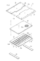
- FIG. 2 is a perspective view showing a template, a mesh member, a lattice member, and an inhibition member corresponding to one absorbent core in a flat shape.
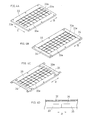
- FIGS. 3A and 3B are a plan view and a side view, respectively, showing a part of the stacking drum in a developed state.
- 4A to 4C are perspective views showing modified examples of the lattice member, respectively.
- FIG. 4D is a side view showing an enlarged end portion of the lattice member of the modified example of FIG. 4C.
- the manufacturing apparatus is further provided with a lattice member that supports the mesh member from the inner peripheral surface side, and the inhibition member is disposed on the inner peripheral surface side of the lattice member.
- the conventional general structure can be used as it is, and the device can be easily improved.
- the absorptive core manufactured by this manufacturing apparatus is used as a core of an incontinence pad other than disposable pants and diapers, for example, and has, for example, an hourglass shape.
- the manufacturing apparatus includes a supply device 1, a fiber drum 2, a conveyor 4, a cutter 5, and an anvil 6.
- the supply device 1 includes a dome-shaped case 10 and a defibrator 11.
- the defibrating machine 11 defibrates (pulverizes) the pulp supplied from upstream to produce fluff pulp (fiber).
- the fluff pulp fills the case 10 and is piled on the pile drum 2 because the inside of the pile drum 2 is set to a negative pressure.
- Such defibration and stacking are well-known techniques, and are disclosed in, for example, Patent Document 1.
- the granular material (superabsorbent polymer particle) of the high molecular compound with a high absorption capability called what is called a sap may be added.
- the stacking drum 2 includes a plurality or a plurality of segments 3 arranged along the circumferential direction R.
- FIG. 2 shows the components of the one segment 3 exploded and flatly developed.
- Each segment 3 includes a template 31, a mesh member 32, a lattice member 33 and an inhibition member 34.
- the mesh member 32 has a large number of through holes 32a formed in a thin metal plate by a known etching process.
- the through-hole 32a is set to a size that allows air to pass through and receives the fibers and the sap.
- a pair of the template 31 is provided, for example, and disposed on the outer peripheral surface side of the mesh member 32 to form the stacking recess 30. For convenience of drawing, the mesh of the mesh member 32 is enlarged and partially displayed.
- the pair of templates 31, 31 are separated from each other in the width direction D, and a space between them forms a fiber stacking recess 30.
- the fibers stacked in the stacked fiber recess 30 become the absorbent core of each wearing article.
- the fiber drum 2 shown in FIG. 1 sucks the fibers supplied from the supply device 1 inward from the outer peripheral surface 2f while continuously rotating in the circumferential direction R, so that the fibers are shown in FIG. 3A. Are continuously stacked on the outer peripheral surface 2 f of the predetermined stacking recess 30.
- the lattice member 33 in FIG. 2 is formed by a crosspiece 33a having a small thickness in the width direction D and the circumferential direction R so as not to inhibit fiber suction.
- the lattice member 33 is in contact with the mesh member 32 and supports the inner peripheral surface of the mesh member 32 that is weak against external force. That is, the inner peripheral surface side 32f of the mesh member 32 of FIG. 3B is supported, and the inhibition member 34 is disposed on the inner peripheral surface side 32f of the lattice member 33.
- the inhibition members 34 are disposed at both ends in the circumferential direction R of one segment 3, and the amount of fibers to be stacked between the absorbent cores C that are continuous to each other is reduced as shown in FIG. Inhibits the suction of the fibers so that.
- the width of the inhibition member 34 in FIG. 2 in the circumferential direction R is larger than the width of each bar 33 a of the lattice member 33.
- the obstructing member 34 is arranged so as to cover the ends on the inner peripheral surface side of the adjacent lattice members 33, 33. As shown in FIG.
- the width in the circumferential direction R of the bars 33e at both ends in the circumferential direction R of the bars 33a of the lattice member 33 is not provided separately from the width of the other bars 33a.
- the inhibition member 34 may be formed by the crosspieces 33e at both ends.
- the inhibition member 34 may be disposed between the ends of the adjacent lattice members 33. That is, for example, as shown in FIG. 4B, the length along the circumferential direction R of the lattice member 33 may be shortened so that the inhibition members 34 and 34 are disposed at both ends of the lattice member 33. Further, as shown in FIGS. 4C and 4D (enlarged side view of the end of the lattice member 33 in FIG. 4C), a thin portion is formed at the end in the circumferential direction R of the lattice member 33, and the adjacent lattice members 33, The obstructing member 34 may be arranged in a thin portion at the end of 33.
- a carrier web W supplied from a conveyor 4 is overlaid on the stacked continuous core C. Thereafter, the continuous core C and the carrier web W are integrally unwound from the stacking drum 2.
- the portion where the stacking is inhibited by the inhibiting member 34 is a thin portion Co.
- the thin portion Co is formed on the outer peripheral side of the continuous core C, while the inhibiting member 34 is disposed on the inner peripheral surface side of the mesh member 32. That is, the outer peripheral surface of the mesh member 32 in FIG. 2 has no ridges for forming the thin portion Co. Therefore, when the continuous core C is unwound from the stacking drum 2, the protrusion does not engage with the continuous core C and the continuous core C is not easily deformed.
- the continuous core C is sequentially cut in units of individual wearing articles by the cutter 5 and the anvil 6 in each thin portion Co. At this time, since the continuous core C is cut at the thin portion Co, the cutting is easy.
- the shape of the stacking concave portion 30 may be a rectangle.
- the inhibition member 34 may be disposed on the inner peripheral surface side of the mesh member 32 without providing the lattice member 33. Accordingly, such changes and modifications are to be construed as within the scope of the present invention as defined by the claims.
- the present invention can be used for an apparatus for manufacturing an absorbent core for disposable wearing articles.
- Feeder 10 Case 11: Defibrator 2: Stacking drum 2f: Outer peripheral surface 3: Segment 30: Stacking recess 31: Template 32: Mesh member 32f: Inner peripheral surface side 33: Lattice member 33a, 33e: Crosspiece 34: Inhibiting member 4: Conveyor 5: Cutter 6: Anvil C: Continuous core Co: Thin portion R: Circumferential direction D: Width direction W: Carrier web
Landscapes
- Health & Medical Sciences (AREA)
- Engineering & Computer Science (AREA)
- Vascular Medicine (AREA)
- Epidemiology (AREA)
- Biomedical Technology (AREA)
- Heart & Thoracic Surgery (AREA)
- Manufacturing & Machinery (AREA)
- Life Sciences & Earth Sciences (AREA)
- Animal Behavior & Ethology (AREA)
- General Health & Medical Sciences (AREA)
- Public Health (AREA)
- Veterinary Medicine (AREA)
- Absorbent Articles And Supports Therefor (AREA)
Abstract
粉砕された繊維を供給する供給装置(1)と、供給装置(1)から供給された繊維を外周面(2f)から内側に向かって吸引しながら、繊維を所定の積繊凹部(30)に外周面(2f)に連続的に積繊する積繊ドラム(2)とを備え、ドラム(2)は、エアを通し、かつ、繊維を受け止めるためのメッシュ部材(32)と、メッシュ部材(32)の外周面側に配置され凹部(30)を形成するための型板(31)と、互いに連続する吸収性コア(C)の間において、積繊される繊維の量が少なくなるように、繊維の吸引を阻害する阻害部材(34)とを備え、阻害部材(34)がメッシュ部材(32)の内周面側(32f)に配置されている。
Description
本発明は使い捨て着用物品の吸収性コアの製造装置に関する。
この種の吸収性コアを製造する方法としては、一般に、粉砕した繊維を積繊ドラムの外周に連続して形成された積繊凹部に吸着させて吸収体の連続体を形成している。
下記の特許文献1においては、積繊凹部には所定のピッチで前記凹部を幅方向に横切る凸条が設けられており、連続体に薄肉部を所定のピッチで形成する。これにより、連続体を薄肉部で切断容易としている。
しかし、前記先行技術では、凸条が凹部内に設けられているため、吸収体の連続体を凹部から取り出して次の搬送手段に渡す際に、連続体が凸条に引っ掛かり、連続体が崩れてしまうという問題が生じ易い。
したがって、本発明の目的は、積繊ドラムに積繊された連続体が型崩れしにくい使い捨て着用物品の吸収性コアの製造装置を提供することである。
本発明は粉砕された繊維を供給する供給装置と、
前記供給装置から供給された前記繊維を外周面から内側に向かって吸引しながら、前記繊維を所定の積繊凹部に前記外周面に連続的に積繊する積繊ドラムとを備え、前記ドラムは、
エアを通し、かつ、前記繊維を受け止めるためのメッシュ部材と、
前記メッシュ部材の外周面側に配置され前記凹部を形成するための型板と、
互いに連続する吸収性コアの間において、積繊される繊維の量が少なくなるように、前記繊維の吸引を阻害する阻害部材とを備え、
前記阻害部材が前記メッシュ部材の内周面側に配置されていることを特徴とする製造装置である。
前記供給装置から供給された前記繊維を外周面から内側に向かって吸引しながら、前記繊維を所定の積繊凹部に前記外周面に連続的に積繊する積繊ドラムとを備え、前記ドラムは、
エアを通し、かつ、前記繊維を受け止めるためのメッシュ部材と、
前記メッシュ部材の外周面側に配置され前記凹部を形成するための型板と、
互いに連続する吸収性コアの間において、積繊される繊維の量が少なくなるように、前記繊維の吸引を阻害する阻害部材とを備え、
前記阻害部材が前記メッシュ部材の内周面側に配置されていることを特徴とする製造装置である。
本発明において、阻害部材は互いに連続する吸収性コアの間において、積繊される繊維の量が少なくなるように、エアおよび前記繊維の吸引を阻害する。そのため、吸収性コアの連続体には、各製品単位の吸収性コアの間に積繊量の少ない薄肉部が所定のピッチで形成される。したがって、前記薄肉部において前記連続体を切断するのが容易になる。
一方、本発明においては前記阻害部材がメッシュ部材の外周面側ではなく、内周面側に配置されている。したがって、前記連続体を積繊ドラムから巻き出す(他の装置に渡す)際に、前記阻害部材が邪魔になったり係合したりして、吸収性コアが型崩れするおそれがない。
一方、本発明においては前記阻害部材がメッシュ部材の外周面側ではなく、内周面側に配置されている。したがって、前記連続体を積繊ドラムから巻き出す(他の装置に渡す)際に、前記阻害部材が邪魔になったり係合したりして、吸収性コアが型崩れするおそれがない。
好ましくは、前記メッシュ部材を内周面側から支持する格子部材を更に備え、前記阻害部材は前記格子部材の内周面側に配置されている製造装置である。
この場合、従来の一般的な構造をそのまま利用でき、装置の改良が容易になる。
以下、本発明の一実施例を図面にしたがって説明する。
本製造装置により製造される吸収性コアは、たとえば使い捨てパンツやオムツの他に失禁パッドなどのコアとして用いられ、例えば砂時計型の形状を有する。
本製造装置により製造される吸収性コアは、たとえば使い捨てパンツやオムツの他に失禁パッドなどのコアとして用いられ、例えば砂時計型の形状を有する。
図1に示すように、本製造装置は供給装置1、積繊ドラム2、コンベヤ4、カッター5およびアンビル6を備える。
供給装置1はドーム状のケース10と解繊機11とを備える。解繊機11は上流から供給されるパルプを繊維状に解繊(粉砕)してフラッフパルプ(繊維)を生成する。フラッフパルプはケース10内に充満すると共に、積繊ドラム2の内部が負圧に設定されていることにより、積繊ドラム2上に積繊される。このような解繊および積繊は周知の技術であり、たとえば、前記特許文献1に開示されている。
なお、吸収性コアを構成する素材として、いわゆるサップと呼ばれる高い吸収能力を持つ高分子化合物の粒状物(高吸水性ポリマー粒子)が添加されてもよい。
なお、吸収性コアを構成する素材として、いわゆるサップと呼ばれる高い吸収能力を持つ高分子化合物の粒状物(高吸水性ポリマー粒子)が添加されてもよい。
前記積繊ドラム2は周方向Rに沿って並んだ複数ないし多数のセグメント3を備える。
作図の便宜上、図2は前記1つのセグメント3の構成部品を分解した上で平坦に展開して示す。各セグメント3は型板31、メッシュ部材32、格子部材33および阻害部材34を備える。
作図の便宜上、図2は前記1つのセグメント3の構成部品を分解した上で平坦に展開して示す。各セグメント3は型板31、メッシュ部材32、格子部材33および阻害部材34を備える。
前記メッシュ部材32は、薄い金属板に周知のエッチング加工により多数ないし無数の貫通孔32aが形成されている。前記貫通孔32aは、エアを通し、かつ、前記繊維および前記サップを受け止めることのできる大きさに設定されている。前記型板31は例えば一対設けられ前記メッシュ部材32の外周面側に配置され積繊凹部30を形成する。
なお、作図の便宜上、メッシュ部材32のメッシュは拡大して、かつ、部分的に表示している。
なお、作図の便宜上、メッシュ部材32のメッシュは拡大して、かつ、部分的に表示している。
一対の型板31,31は幅方向Dに互いに離間しており、その間の空間は積繊凹部30を形成している。この積繊凹部30に積繊された繊維が個々の着用物品の吸収性コアとなる。
すなわち、図1の積繊ドラム2は、周方向Rに連続的に回転しながら前記供給装置1から供給された前記繊維を外周面2fから内側に向かって吸引することで、前記繊維を図3Aの所定の積繊凹部30の前記外周面2fに連続的に積繊する。
図2の前記格子部材33は、繊維の吸引を阻害しないように幅方向Dおよび周方向Rの厚みが小さい桟33aにより形成されている。この格子部材33はメッシュ部材32に接しており、外力に弱いメッシュ部材32の内周面を支持している。すなわち、図3Bの前記メッシュ部材32の内周面側32fを支持しており、前記阻害部材34は前記格子部材33の内周面側32fに配置されている。
前記阻害部材34は1つのセグメント3の周方向Rの両端に配置され、互いに連続する吸収性コアCの間において、図1に示すように積繊される繊維の量が少なくなって薄肉部Coが形成されるように、前記繊維の吸引を阻害する。図2の前記阻害部材34の周方向R方向の幅は格子部材33の各桟33aの幅よりも大きい。図3Bに示すように、隣り合う格子部材33,33の内周面側の端部同士を覆うように阻害部材34が配置されている。
なお、図4Aに示すように、阻害部材34を別途設けずに格子部材33の各桟33aのうち、周方向Rの両端の桟33eの周方向R方向の幅を他の桟33aの幅よりも大きくして当該両端の桟33eで阻害部材34が形成されてもよい。
なお、図4Aに示すように、阻害部材34を別途設けずに格子部材33の各桟33aのうち、周方向Rの両端の桟33eの周方向R方向の幅を他の桟33aの幅よりも大きくして当該両端の桟33eで阻害部材34が形成されてもよい。
また、阻害部材34が隣り合う格子部材33の端部同士の間に配置されてもよい。
すなわち、たとえば、図4Bに示すように、格子部材33の周方向Rに沿った長さを短くして同格子部材33の両端に阻害部材34,34が配置されるようにしてもよい。
また、図4Cおよび図4D(図4Cの格子部材33の端部の拡大側面図)に示すように、格子部材33の周方向Rの端部に薄肉部を形成し、隣り合う格子部材33,33の端部の薄肉部に阻害部材34が配置されるようにしてもよい。
すなわち、たとえば、図4Bに示すように、格子部材33の周方向Rに沿った長さを短くして同格子部材33の両端に阻害部材34,34が配置されるようにしてもよい。
また、図4Cおよび図4D(図4Cの格子部材33の端部の拡大側面図)に示すように、格子部材33の周方向Rの端部に薄肉部を形成し、隣り合う格子部材33,33の端部の薄肉部に阻害部材34が配置されるようにしてもよい。
図1に示すように、前記積繊された連続コアCには、コンベヤ4から供給されたキャリアウエブWが重ねられる。その後、前記連続コアCとキャリアウエブWとは一体となって積繊ドラム2から巻き出される。
一方、前記連続コアCの積繊において、阻害部材34により積繊が阻害された部位は薄肉部Coとなる。しかし、薄肉部Coは連続コアCの外周側に形成されており、一方、阻害部材34はメッシュ部材32の内周面側に配置されている。つまり、図2のメッシュ部材32の外周面には薄肉部Coを形成するための凸条がない。したがって、連続コアCが積繊ドラム2から巻き出される際に、該凸条が連続コアCに係合等することがなく、連続コアCが型崩れしにくい。
前記巻出後、連続コアCは各薄肉部Coにおいて、カッター5およびアンビル6により個々の着用物品の単位で次々に切断される。この際、連続コアCを薄肉部Coにおいて切断するので、前記切断が容易である。
以上のとおり、図面を参照しながら一実施例を説明したが、当業者であれば、本明細書を見て、自明な範囲内で種々の変更および修正を容易に想定するであろう。
たとえば、積繊凹部30の形状は長方形であってもよい。
また、格子部材33を設けることなくメッシュ部材32の内周面側に阻害部材34を配置してもよい。
したがって、そのような変更および修正は、請求の範囲から定まる本発明の範囲内のものと解釈される。
たとえば、積繊凹部30の形状は長方形であってもよい。
また、格子部材33を設けることなくメッシュ部材32の内周面側に阻害部材34を配置してもよい。
したがって、そのような変更および修正は、請求の範囲から定まる本発明の範囲内のものと解釈される。
本発明は使い捨て着用物品の吸収性コアの製造装置に利用できる。
1:供給装置 10:ケース 11:解繊機
2:積繊ドラム 2f:外周面
3:セグメント 30:積繊凹部 31:型板 32:メッシュ部材 32f:内周面側 33:格子部材 33a,33e:桟 34:阻害部材
4:コンベヤ
5:カッター
6:アンビル
C:連続するコア Co:薄肉部
R:周方向
D:幅方向
W:キャリアウエブ
2:積繊ドラム 2f:外周面
3:セグメント 30:積繊凹部 31:型板 32:メッシュ部材 32f:内周面側 33:格子部材 33a,33e:桟 34:阻害部材
4:コンベヤ
5:カッター
6:アンビル
C:連続するコア Co:薄肉部
R:周方向
D:幅方向
W:キャリアウエブ
Claims (2)
- 使い捨て着用物品の吸収性コアの製造装置であって、
粉砕された繊維を供給する供給装置と、
前記供給装置から供給された前記繊維を外周面から内側に向かって吸引しながら、前記繊維を所定の積繊凹部に前記外周面に連続的に積繊する積繊ドラムとを備え、前記ドラムは、
エアを通し、かつ、前記繊維を受け止めるためのメッシュ部材と、
前記メッシュ部材の外周面側に配置され前記凹部を形成するための型板と、
互いに連続する吸収性コアの間において、積繊される繊維の量が少なくなるように、前記繊維の吸引を阻害する阻害部材とを備え、
前記阻害部材が前記メッシュ部材の内周面側に配置されていることを特徴とする製造装置。 - 請求項1において、前記メッシュ部材を内周面側から支持する格子部材を更に備え、前記阻害部材は前記格子部材の内周面側に配置されている製造装置。
Priority Applications (2)
| Application Number | Priority Date | Filing Date | Title |
|---|---|---|---|
| JP2014539722A JP6282594B2 (ja) | 2012-10-05 | 2013-09-30 | 使い捨て着用物品の吸収性コアの製造装置 |
| CN201380051316.7A CN104684523B (zh) | 2012-10-05 | 2013-09-30 | 一次性穿着物品的吸收性芯的制造方法 |
Applications Claiming Priority (2)
| Application Number | Priority Date | Filing Date | Title |
|---|---|---|---|
| JP2012222800 | 2012-10-05 | ||
| JP2012-222800 | 2012-10-05 |
Publications (1)
| Publication Number | Publication Date |
|---|---|
| WO2014054566A1 true WO2014054566A1 (ja) | 2014-04-10 |
Family
ID=50434893
Family Applications (1)
| Application Number | Title | Priority Date | Filing Date |
|---|---|---|---|
| PCT/JP2013/076504 Ceased WO2014054566A1 (ja) | 2012-10-05 | 2013-09-30 | 使い捨て着用物品の吸収性コアの製造装置 |
Country Status (3)
| Country | Link |
|---|---|
| JP (1) | JP6282594B2 (ja) |
| CN (1) | CN104684523B (ja) |
| WO (1) | WO2014054566A1 (ja) |
Citations (5)
| Publication number | Priority date | Publication date | Assignee | Title |
|---|---|---|---|---|
| US4388056A (en) * | 1981-07-06 | 1983-06-14 | The Procter & Gamble Company | Apparatus for continuously making an air-laid fibrous web having patterned basis weight distribution |
| JPS62206071A (ja) * | 1985-12-10 | 1987-09-10 | キンバリ− クラ−ク コ−ポレ−シヨン | 軽又は重毛羽区域の制御された地合い |
| US6283669B1 (en) * | 1997-10-29 | 2001-09-04 | Jerry L. Toney | Concentricity stabilizer which is both a structural coupling and an alignment device |
| JP2006132009A (ja) * | 2004-11-02 | 2006-05-25 | Kao Corp | 吸収体の製造装置 |
| JP2013099522A (ja) * | 2011-10-19 | 2013-05-23 | Kao Corp | 積繊装置 |
Family Cites Families (1)
| Publication number | Priority date | Publication date | Assignee | Title |
|---|---|---|---|---|
| US4666647A (en) * | 1985-12-10 | 1987-05-19 | Kimberly-Clark Corporation | Apparatus and process for forming a laid fibrous web |
-
2013
- 2013-09-30 JP JP2014539722A patent/JP6282594B2/ja active Active
- 2013-09-30 WO PCT/JP2013/076504 patent/WO2014054566A1/ja not_active Ceased
- 2013-09-30 CN CN201380051316.7A patent/CN104684523B/zh active Active
Patent Citations (5)
| Publication number | Priority date | Publication date | Assignee | Title |
|---|---|---|---|---|
| US4388056A (en) * | 1981-07-06 | 1983-06-14 | The Procter & Gamble Company | Apparatus for continuously making an air-laid fibrous web having patterned basis weight distribution |
| JPS62206071A (ja) * | 1985-12-10 | 1987-09-10 | キンバリ− クラ−ク コ−ポレ−シヨン | 軽又は重毛羽区域の制御された地合い |
| US6283669B1 (en) * | 1997-10-29 | 2001-09-04 | Jerry L. Toney | Concentricity stabilizer which is both a structural coupling and an alignment device |
| JP2006132009A (ja) * | 2004-11-02 | 2006-05-25 | Kao Corp | 吸収体の製造装置 |
| JP2013099522A (ja) * | 2011-10-19 | 2013-05-23 | Kao Corp | 積繊装置 |
Also Published As
| Publication number | Publication date |
|---|---|
| CN104684523B (zh) | 2017-03-08 |
| JPWO2014054566A1 (ja) | 2016-08-25 |
| CN104684523A (zh) | 2015-06-03 |
| JP6282594B2 (ja) | 2018-02-21 |
Similar Documents
| Publication | Publication Date | Title |
|---|---|---|
| EP3069703A1 (en) | Absorbent body and device for producing same | |
| JP5404286B2 (ja) | ウェブ搬送装置 | |
| JP4528622B2 (ja) | 無駄が最小の形状をもつ幅方向嵌まり合い形吸収体パッド | |
| WO2011068062A1 (ja) | 吸収体の製造方法及び製造装置 | |
| JP2010227543A (ja) | 吸収体成型転写機構及び吸収性物品の製造方法 | |
| TW201117779A (en) | Folding device | |
| JP5953296B2 (ja) | 吸収体の製造装置 | |
| JP2003199790A (ja) | 使い捨て着用物品の製造方法 | |
| JP5508034B2 (ja) | 切断装置 | |
| RU2665904C1 (ru) | Бесцеллюлозная впитывающая сердцевина и способ формирования сердцевины | |
| JP5723859B2 (ja) | 吸収性物品に係る吸収体の製造装置、及び製造方法 | |
| JP6282594B2 (ja) | 使い捨て着用物品の吸収性コアの製造装置 | |
| JP6982453B2 (ja) | 吸収体の製造方法及び吸収体の製造装置 | |
| US11850129B2 (en) | Apparatus and method for manufacturing absorbent core used in disposable wearable article | |
| CN110636821B (zh) | 吸收体和吸收性物品的制造方法、以及吸收体和吸收性物品的制造装置 | |
| JP4786746B2 (ja) | エアレイド構造を製造するための装置 | |
| CN102791915A (zh) | 处理层压产品的设备 | |
| EP4005543B1 (en) | Manufacturing device and manufacturing method of absorber | |
| JP6255232B2 (ja) | 吸収体の製造装置 | |
| JP5822380B2 (ja) | 吸収体の製造方法 | |
| JP5709580B2 (ja) | 吸収体を製造する装置及び方法 | |
| EP4410253A1 (en) | Device and method for producing absorbent core of disposal wearable article | |
| JP6647009B2 (ja) | 吸収体の製造装置及び製造方法 | |
| JP2012176099A5 (ja) | ||
| JP5326000B2 (ja) | シームレスベルトの形成方法 |
Legal Events
| Date | Code | Title | Description |
|---|---|---|---|
| 121 | Ep: the epo has been informed by wipo that ep was designated in this application |
Ref document number: 13843994 Country of ref document: EP Kind code of ref document: A1 |
|
| ENP | Entry into the national phase |
Ref document number: 2014539722 Country of ref document: JP Kind code of ref document: A |
|
| NENP | Non-entry into the national phase |
Ref country code: DE |
|
| 122 | Ep: pct application non-entry in european phase |
Ref document number: 13843994 Country of ref document: EP Kind code of ref document: A1 |