WO2014054504A1 - 電圧均等化装置および電圧均等化方法 - Google Patents
電圧均等化装置および電圧均等化方法 Download PDFInfo
- Publication number
- WO2014054504A1 WO2014054504A1 PCT/JP2013/076126 JP2013076126W WO2014054504A1 WO 2014054504 A1 WO2014054504 A1 WO 2014054504A1 JP 2013076126 W JP2013076126 W JP 2013076126W WO 2014054504 A1 WO2014054504 A1 WO 2014054504A1
- Authority
- WO
- WIPO (PCT)
- Prior art keywords
- voltage
- battery
- pulse width
- width modulation
- batteries
- Prior art date
- Legal status (The legal status is an assumption and is not a legal conclusion. Google has not performed a legal analysis and makes no representation as to the accuracy of the status listed.)
- Ceased
Links
Images






Classifications
-
- H—ELECTRICITY
- H02—GENERATION; CONVERSION OR DISTRIBUTION OF ELECTRIC POWER
- H02J—ELECTRIC POWER NETWORKS; CIRCUIT ARRANGEMENTS OR SYSTEMS FOR SUPPLYING OR DISTRIBUTING ELECTRIC POWER; SYSTEMS FOR STORING ELECTRIC ENERGY
- H02J7/00—Circuit arrangements for charging or discharging batteries or for supplying loads from batteries
- H02J7/50—Circuit arrangements for charging or discharging batteries or for supplying loads from batteries acting upon multiple batteries simultaneously or sequentially
- H02J7/52—Circuit arrangements for charging or discharging batteries or for supplying loads from batteries acting upon multiple batteries simultaneously or sequentially for charge balancing, e.g. equalisation of charge between batteries
- H02J7/54—Passive balancing, e.g. using resistors or parallel MOSFETs
-
- H—ELECTRICITY
- H01—ELECTRIC ELEMENTS
- H01M—PROCESSES OR MEANS, e.g. BATTERIES, FOR THE DIRECT CONVERSION OF CHEMICAL ENERGY INTO ELECTRICAL ENERGY
- H01M10/00—Secondary cells; Manufacture thereof
- H01M10/42—Methods or arrangements for servicing or maintenance of secondary cells or secondary half-cells
- H01M10/44—Methods for charging or discharging
- H01M10/441—Methods for charging or discharging for several batteries or cells simultaneously or sequentially
-
- H—ELECTRICITY
- H01—ELECTRIC ELEMENTS
- H01M—PROCESSES OR MEANS, e.g. BATTERIES, FOR THE DIRECT CONVERSION OF CHEMICAL ENERGY INTO ELECTRICAL ENERGY
- H01M10/00—Secondary cells; Manufacture thereof
- H01M10/42—Methods or arrangements for servicing or maintenance of secondary cells or secondary half-cells
- H01M10/425—Structural combination with electronic components, e.g. electronic circuits integrated to the outside of the casing
- H01M2010/4271—Battery management systems including electronic circuits, e.g. control of current or voltage to keep battery in healthy state, cell balancing
-
- Y—GENERAL TAGGING OF NEW TECHNOLOGICAL DEVELOPMENTS; GENERAL TAGGING OF CROSS-SECTIONAL TECHNOLOGIES SPANNING OVER SEVERAL SECTIONS OF THE IPC; TECHNICAL SUBJECTS COVERED BY FORMER USPC CROSS-REFERENCE ART COLLECTIONS [XRACs] AND DIGESTS
- Y02—TECHNOLOGIES OR APPLICATIONS FOR MITIGATION OR ADAPTATION AGAINST CLIMATE CHANGE
- Y02E—REDUCTION OF GREENHOUSE GAS [GHG] EMISSIONS, RELATED TO ENERGY GENERATION, TRANSMISSION OR DISTRIBUTION
- Y02E60/00—Enabling technologies; Technologies with a potential or indirect contribution to GHG emissions mitigation
- Y02E60/10—Energy storage using batteries
Definitions
- the present invention relates to a voltage equalizing apparatus and a voltage equalizing method for equalizing the voltages of a plurality of batteries.
- the accuracy of equalization when performing voltage equalization processing to equalize the voltage of each battery for multiple batteries connected in series is the voltage measurement accuracy of each battery measured at the time of discharging or charging Depends on. For this reason, in order to accurately measure the voltage, the voltage must be measured using an accurate and expensive voltmeter.
- a charge state equalization apparatus that equalizes the charge state of each cell for an assembled battery formed by connecting a plurality of cells in series.
- a charge state equalization apparatus includes a plurality of discharge circuits connected in parallel to each cell to discharge each cell, a plurality of voltage measurement circuits and a control circuit connected to each discharge circuit to measure a voltage across each cell It has.
- the control circuit includes means for calculating the equalization target voltage based on the measured voltage before the start of discharge, and means for starting discharge for a cell whose both-end voltage exceeds the equalization target voltage.
- the corrected equalized target voltage is calculated by correcting the equalized target voltage based on the difference between the measured voltage before the start of discharge and the measured voltage after a certain time has elapsed since the start of discharge. And means for terminating the discharge when the measured voltage reaches the corrected equalization target voltage.
- the present invention has been made in view of the above circumstances, and an object thereof is to provide a voltage equalizing apparatus and a voltage equalizing method for equalizing battery voltages with high accuracy.
- the voltage equalization apparatus which is one of the embodiments includes an assembled battery, an inductor, a switch, a voltage measurement unit, a determination unit, and a pulse width modulation unit.
- Bundled batteries are connected in series.
- One terminal of the inductor is connected to the negative terminal of the battery and the positive terminal of the battery adjacent to the battery.
- One switch is connected between the positive terminal of the battery and the other terminal of the inductor, and the other switch is connected between the negative terminal of the battery adjacent to the battery and the other terminal of the inductor.
- the voltage measurement unit measures the voltage of each battery.
- the pulse width modulation unit controls the opening and closing of one switch and the other switch to execute a pulse width modulation process for voltage equalization.
- the determination unit calculates the average voltage of the battery, determines the voltage difference between the average voltage and the battery, and determines whether the voltage difference is higher than a first threshold determined by the allowable error value of the voltage measurement unit.
- the pulse width modulation unit executes a pulse width modulation process for equalizing the voltage when the voltage difference is higher than the first threshold value.
- the pulse width modulation unit The pulse width modulation process is executed by changing to 50%.
- the voltage equalization apparatus which is one of the other embodiments includes an assembled battery, an inductor, a switch, a voltage measurement unit, an adjustment voltage calculation unit, a target voltage calculation unit, a determination unit, and a pulse width modulation unit.
- Bundled batteries are connected in series.
- One terminal of the inductor is connected to the negative terminal of the battery and the positive terminal of the battery adjacent to the battery.
- One switch is connected between the positive terminal of the battery and the other terminal of the inductor, and the other switch is connected between the negative terminal of the battery adjacent to the battery and the other terminal of the inductor.
- the voltage measurement unit measures the voltage of each battery.
- the pulse width modulation unit controls the opening and closing of one switch and the other switch to execute a pulse width modulation process for voltage equalization.
- the adjustment voltage calculation unit obtains an adjustment voltage that is a difference between the battery start voltage before the start of the pulse width modulation process and the battery voltage after the lapse of a predetermined time.
- the target voltage calculation unit obtains the average voltage between the battery and the adjacent battery, and obtains the target voltage of the battery using the average voltage and the battery adjustment voltage.
- the determination unit calculates the average voltage of the battery, determines the voltage difference between the average voltage and the battery, and determines whether the voltage difference is higher than a first threshold determined by the allowable error value of the voltage measurement unit.
- the pulse width modulation unit executes the pulse width modulation process when the voltage difference is higher than the first threshold, stops the pulse width modulation process when the battery voltage reaches the target voltage, Then, the pulse width is changed to 50% duty and the pulse width modulation process is executed.
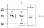
- FIG. 3 is a diagram illustrating an example of a control unit according to Embodiment 1.
- FIG. It is a figure which shows the relationship between 1 set of the battery to discharge, and the battery to charge.
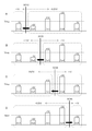
- FIG. 3 is a flowchart showing an example of the operation of the voltage equalizing apparatus in the first embodiment. It is a figure which shows the change of the voltage and electric current in Embodiment 1.
- FIG. It is a figure which shows one Example of the control part in Embodiment 2.
- FIG. FIG. 10 is a flowchart showing an example of the operation of the voltage equalization apparatus in Embodiment 2. It is a figure which shows the change of the voltage and electric current in Embodiment 2.
- FIG. 10 is a flowchart showing an example of voltage equalization operation in the third exemplary embodiment.
- FIG. 10 is a diagram for explaining an operation of the third embodiment. It is a flowchart which shows one Example of the operation
- Embodiment 1 will be described.
- FIG. 1 is a diagram showing an embodiment of a voltage equalizing apparatus.
- the voltage equalization apparatus of FIG. 1 has an assembled battery and a voltage equalization circuit.
- the assembled battery is a circuit in which a plurality of batteries 3a to 3d are connected in series.
- the voltage equalization circuit includes a control unit 1, a storage unit 2, voltage measurement units 4a to 4d, current measurement units 5a to 5c, coils L1 to L3 (inductors), and switches SW1 to SW6.
- the control unit 1 performs PWM (PulseSWWidthPWMModulation) control of the switches SW1 to SW6, so that the batteries 3a to 3d are used using the coils L1 to L3. Make the voltage even.
- PWM PulseSWWidthPWMModulation
- the control unit 1 may be a central processing unit (CPU), a multi-core CPU, or a programmable device (such as a field programmable gate array (FPGA) or a programmable logic device (PLD)).
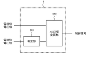
- the control unit 1 includes, for example, a determination unit 201 and a pulse width modulation unit 202 described later.
- the storage unit 2 may be a memory such as a Read Only Memory (ROM) or a Random Access Memory (RAM), a hard disk, or the like. Data such as parameter values and variable values may be recorded in the storage unit 2 or may be used as a work area at the time of execution.
- ROM Read Only Memory
- RAM Random Access Memory
- the batteries 3a to 3d may be secondary batteries.
- a lithium ion secondary battery, a nickel hydride secondary battery, or the like can be considered.
- four batteries are used for explanation, but the number of batteries is not limited to four.
- the data measured by the voltage measuring units 4 a to 4 d is output to the control unit 1.
- Current measuring units 5a to 5c measure current. For example, an ammeter can be considered. The data measured by the current measuring units 5a to 5c is output to the control unit 1.
- the currents flowing through the batteries 3a to 3d during charging / discharging are determined using the currents measured by the current measuring units 5a to 5c. How to determine the currents flowing through the batteries 3a to 3d are as follows. The method is not limited to the above method. For example, an ammeter may be connected in series to the negative electrode side of each of the batteries 3a to 3d, and the current flowing through each of the batteries 3a to 3d may be measured and obtained.
- the coils L1 to L3 are used for charging the electric power discharged from the discharging batteries for each set in the coils L1 to L3, and then supplying the electric power stored in the coils L1 to L3 to the charging battery. .
- the switches SW1 to SW6 are switches used for performing a voltage equalization process.
- the switches SW1 to SW6 use, for example, MOSFETs (Metal-Oxide-Semiconductor Field-Effect Transistors) or relays.
- voltage measuring units 4a to 4d are connected to both ends of the batteries 3a to 3d, respectively.
- the negative electrode terminal of the battery 3a, the positive electrode terminal of the battery 3b, and one terminal of the current measuring unit 5a are connected, and the other terminal of the current measuring unit 5a is connected to one terminal of the coil L1.
- the other terminal of the coil L1 is connected to one terminal of the switches SW1 and SW2, and the other terminal of the switch SW1 is connected to the positive terminal of the battery 3a.
- the other terminal of the switch SW2 is connected to the negative terminal of the battery 3b.
- the negative terminal of the battery 3b, the positive terminal of the battery 3c, and one terminal of the current measuring unit 5b are connected, and the other terminal of the current measuring unit 5b is connected to one terminal of the coil L2.
- the other terminal of the coil L2 is connected to one terminal of the switches SW3 and SW4, and the other terminal of the switch SW3 is connected to the positive terminal of the battery 3b.
- the other terminal of the switch SW4 is connected to the negative terminal of the battery 3c.
- the negative terminal of the battery 3c, the positive terminal of the battery 3d, and one terminal of the current measuring unit 5c are connected, and the other terminal of the current measuring unit 5c is connected to one terminal of the coil L3.
- the other terminal of the coil L3 is connected to one terminal of the switches SW5 and SW6, and the other terminal of the switch SW5 is connected to the positive terminal of the battery 3c.
- the other terminal of the switch SW6 is connected to the negative terminal of the battery 3d.
- control unit will be described with reference to FIGS.
- FIG. 2 is a diagram illustrating an embodiment of the control unit.
- FIG. 3 is a diagram showing a relationship between a set of discharging batteries and charging batteries.
- the control unit 1 acquires the voltage measured by the voltage measuring units 4a to 4d and the current measured by the current measuring units 5a to 5c.
- the 2 determines the voltage of the first battery and the second battery connected in series.
- the voltage is a value measured by the voltage measurement unit before starting a pulse width modulation process (voltage equalization process) described later for equalizing the voltages of the first battery and the second battery.
- an average voltage of the voltage of the first battery and the voltage of the second battery is obtained, and the voltage difference between the average voltage Vavg and the voltage of the first battery or the voltage difference between the average voltage and the voltage of the second battery. Ask for. Thereafter, it is determined whether or not the voltage difference is greater than or equal to a first threshold value determined by an allowable error value in voltage measurement of the voltage measurement unit.
- the first threshold value may be determined using, for example, the allowable error of the voltage measurement unit, or may be determined using the maximum allowable error of the voltage measurement unit through experiments or simulations. Alternatively, the first threshold value may be obtained by adding the tolerances of the adjacent voltage measurement units. For example, the allowable error of the voltage measuring unit 4a and the allowable error of the voltage measuring unit 4b may be added and used. Further, it is conceivable to store the first threshold value in the storage unit 2.
- the determination unit 201 acquires the voltage V01 of the battery 3a (first battery) and the voltage V02 of the battery 3b (second battery) before the start of the pulse width modulation process from the respective voltage measurement units 4a and 4b.
- the voltages V01 and V02 include an allowable error.
- between the average voltage Vavg and the voltage V01 or a voltage difference V2
- the determination unit 201 determines whether the voltage difference V1 or the voltage difference V2 is higher than the first threshold value, and transmits the determination result to the pulse width modulation unit 202.
- between the voltage Vn1 of the first battery and the average voltage Vavg, the voltage Vn2 of the second battery, and the average voltage Vavg Voltage difference Vs2
- the pulse width is changed to 50% duty, and pulse width modulation processing (voltage equalization processing) with 50% duty is executed. In this example, it has been proposed to set the duty to 50% as the optimum value. However, in practice, it is desirable to determine the duty in the vicinity of 50% in consideration of the circuit of the voltage equalizing device and the surrounding environment.
- the reason why the pulse width is changed to 50% duty is that the current that flows according to the voltage difference between the voltage of the first battery and the voltage of the second battery by setting the duty to 50% is the first. This is because the voltage difference between the voltage of the second battery and the voltage of the second battery is set to 0V.
- the pulse width modulation unit 202 changes the duty to 50% and stops the pulse width modulation process when the pulse width modulation process is executed for a predetermined time.
- the determined time may be calculated and stored in the storage unit 2 until the voltage difference Vs1 or the voltage difference Vs2 becomes substantially zero after the voltage difference Vs1 or the voltage difference Vs2 becomes zero.
- FIG. 4 is a flowchart showing an example of the operation of the voltage equalizing apparatus according to the first embodiment.
- FIG. 5 is a diagram illustrating changes in voltage and current in the first embodiment. A set of the battery 3a and the battery 3b will be described.
- Control A in FIG. 5 is control that shifts to constant voltage control after voltage equalization with a constant current. In constant voltage control, control is performed based on voltage values measured by the voltage measuring units 4a and 4b.
- Control B in FIG. 5 is control for shifting to pulse width modulation processing with a duty of 50% after voltage equalization with a constant current, and performs control without referring to the voltage values measured by the voltage measuring units 4a and 4b.
- step S401 the control unit 1 acquires the voltages V01 and V02 of the batteries 3a and 3b from the voltage measurement units 4a and 4b. Voltages V01 and V02 are acquired in a period before time t1 from time t0 before the start of the pulse width modulation process of control A and control B in FIG.
- step S402 an average voltage (target voltage in the first embodiment) Vavg of the voltages V01 and V02 acquired by the control unit 1 is obtained.
- step S403 the control unit 1 obtains a voltage difference V1 between the average voltage Vavg and the voltage V01 or a voltage difference V2 between the average voltage Vavg and the voltage V02.
- step S404 the control unit 1 determines whether or not the voltage difference V1 or the voltage difference V2 is higher than the first threshold value. If the voltage difference V1 is higher than the first threshold value (Yes), the process proceeds to step S405. If it is equal to or less than the threshold (No), the process proceeds to step S407.
- step S405 when the voltage difference V1 or the voltage difference V2 is higher than the first threshold, the control unit 1 starts a pulse width modulation process for performing voltage equalization with a constant current. Pulse width modulation processing is performed to equalize the voltage with a constant current from the time t1 of the control A and the control B in FIG.
- reference numerals 501 and 505 denote voltage changes of the battery 3a
- 502 and 506 denote voltage changes of the battery 3b.
- Control A 504 in FIG. 5 indicates a change in current IL
- control B 507 in FIG. 5 indicates a change in current IL.
- step S406 the control unit 1 determines whether or not the voltage difference Vs1 between the current voltage Vn1 of the battery 3a and the average voltage Vavg or the voltage difference Vs2 between the current voltage Vn2 and the average voltage Vavg of the battery 3b is equal to or less than a first threshold value. Determine. When the voltage difference Vs1 or the voltage difference Vs2 is equal to or smaller than the first threshold (Yes), the process proceeds to step S407, and when it is higher than the first threshold (No), the process proceeds to step S406.
- step S407 the control unit 1 starts the pulse width modulation process with a duty of 50%.
- the control B since the pulse width modulation processing is performed with a duty of 50% after the time t2, the voltages of the battery 3a and the battery 3b become equal at the time t3.
- the pulse width modulation process is performed after the time t2 with a duty of 50%, it converges at the time t3.
- the pulse width modulation process is not performed after time t2 with a duty of 50%, and is based on the measurement result of the voltage measuring units 4a and 4b.
- the voltage of the batteries 3a and 3b varies without converging to the obtained average voltage Vavg or the actual average voltage (target voltage).
- the average voltage Vavg obtained in step S402 includes an allowable error of the voltage measuring units 4a and 4b, it is different from the actual average voltage (target voltage), but the pulse width modulation process is performed with a duty of 50%.
- the voltages Vn1 and Vn2 can be brought close to the target voltage. That is, the voltages of the battery 3a and the battery 3b can be accurately and evenly used without using an expensive voltage measuring unit with good measurement accuracy.
- a voltage measuring unit with high measurement accuracy is required to equalize the voltages of the batteries 3a and 3b with high accuracy.
- step S408 it is determined whether or not the determined time has elapsed since the control unit 1 started the pulse width modulation process with a duty of 50%. If the determined time has elapsed (Yes), step S409 is performed. Migrate to If the determined time has not elapsed (No), the pulse width modulation process is continued with a duty of 50% in step S408.
- the determined time is a period represented by time t2 and time t3 of control B in FIG.
- step S409 the control unit 1 ends the pulse width modulation process with a duty of 50%.
- pulse width modulation processing for performing voltage equalization with a constant current is executed.
- the present invention is not limited to a constant current, and for example, a constant voltage may be used.
- the first embodiment it is possible to improve the accuracy of equalizing the battery voltage without using an expensive voltage measurement unit with high measurement accuracy.
- Embodiment 2 will be described.
- the control unit 1 of the voltage equalization circuit according to the second embodiment fixes the pulse width for improving the accuracy of equalizing the battery voltage to 50% duty and the control for shortening the time for equalizing the voltages of the batteries 3a to 3d. To perform pulse width modulation.
- the voltage measured by the voltage measuring units 4a to 4d is equalized.
- the actual voltages of the batteries 3a to 3d deviate from the target average voltage Vavg. That is, from the average voltage Vavg of each set of batteries, the voltage determined by the internal resistance of each of the batteries 3a to 3d and the current flowing through each of the batteries 3a to 3d is the time from when the voltages of the batteries 3a to 3d become equal. It will shift as time passes.
- the control unit 1 includes an adjustment voltage calculation unit 601, a target voltage calculation unit 602, a determination unit 603, a pulse width modulation unit 604, and the like illustrated in FIG.
- FIG. 6 is a diagram illustrating an example of the control unit.
- the control unit 1 monitors whether a constant current is supplied to the batteries 3a to 3d when equalizing the voltage with a constant current.
- the adjustment voltage calculation unit 601 of the control unit 1 starts the first battery before starting the pulse width modulation process that performs voltage equalization with a constant current and after the start of the pulse width modulation process that performs voltage equalization with a constant current.
- a first adjustment voltage that is a difference from the voltage of the first battery after elapse of the determined time is obtained.
- the target voltage calculation unit 602 of the control unit 1 obtains an average voltage from the average of the voltage of the first battery and the voltage of the second battery, and uses the average voltage and the adjustment voltage of the first battery to A first target voltage is obtained, and a second target voltage of the second battery is obtained using the average voltage and the adjustment voltage of the second battery.
- the average voltage Vavg is obtained from the average of the voltage of the battery 3a and the voltage of the battery 3b. Then, the target voltage Vt1 of the battery 3a is obtained using the average voltage Vavg and the adjustment voltage ⁇ V1 of the battery 3a, and the target voltage Vt2 of the battery 3b is obtained using the average voltage Vavg and the adjustment voltage ⁇ V2 of the battery 3b.
- the target voltage Vt1 of the battery to be discharged and the target voltage Vt2 of the battery to be charged are obtained by Equations 1 and 2.
- the unit 603 acquires the voltages of the first battery and the second battery connected in series. Subsequently, an average voltage between the voltage of the first battery and the voltage of the second battery is obtained, and a voltage difference between the average voltage and the voltage of the first battery or a voltage difference between the average voltage and the voltage of the second battery is calculated. Ask.
- the first threshold value may be determined using, for example, the allowable error of the voltage measurement unit, or may be determined using the maximum allowable error of the voltage measurement unit obtained through experiments or simulations. Alternatively, the first threshold value may be obtained by adding the tolerances of the adjacent voltage measurement units. For example, the allowable error of the voltage measuring unit 4a and the allowable error of the voltage measuring unit 4b may be added and used. Further, it is conceivable to store the first threshold value in the storage unit 2.
- the determination unit 603 obtains the start voltage V01 of the battery 3a (first battery) and the start voltage V02 of the battery 3b (second battery) before the start of the pulse width modulation process from the respective voltage measurement units 4a and 4b. .
- the start voltages V01 and V02 include an allowable error.
- between the average voltage Vavg and the start voltage V01 or a voltage difference V2
- the determination unit 603 determines whether the voltage difference V1 or the voltage difference V2 is higher than the first threshold value, and transmits the determination result to the pulse width modulation unit 604.
- the pulse width modulation unit 604 When the voltage difference V1 or the voltage difference V2 is higher than the first threshold, the pulse width modulation unit 604 performs a pulse width modulation process (voltage equalization process) that performs voltage equalization with a constant current. Subsequently, the pulse width modulation unit 604 of the control unit 1 performs a pulse width modulation process when the voltage of the first battery becomes the first target voltage or when the voltage of the second battery becomes the second target voltage. To stop.
- a pulse width modulation process voltage equalization process
- the voltage difference Vs1 between the current voltage Vn1 and the average voltage of the battery 3a or the voltage difference Vs2 between the current voltage Vn2 and the average voltage of the battery 3b is the first voltage.
- the pulse width is changed to 50% duty, and pulse width modulation processing with a duty of 50% is executed.
- the polarization may be canceled, and when the polarization is canceled, the pulse width may be changed to 50% duty and the pulse width modulation processing with 50% duty may be executed.
- the pulse width modulation unit 604 stops the pulse width modulation processing when the duty width is changed to 50% and the pulse width modulation processing is executed for a predetermined time.
- the determined time may be calculated and stored in the storage unit 2 until the voltage difference Vs1 or the voltage difference Vs2 becomes substantially zero after the voltage difference Vs1 or the voltage difference Vs2 becomes zero.
- FIG. 7 is a flowchart showing an example of the operation of the voltage equalizing apparatus according to the second embodiment.
- FIG. 8 is a diagram illustrating changes in voltage and current in the second embodiment. Control 806 in FIG. 8 indicates a change in current IL, and control D 807 in FIG. 8 indicates a change in current IL.
- step S404 of the second embodiment it is determined whether or not the voltage difference V1 or the voltage difference V2 is higher than the first threshold. If the voltage difference V1 is higher than the first threshold (Yes), the process proceeds to step S701. When the voltage difference V1 or the voltage difference V2 is equal to or smaller than the first threshold (No), the process proceeds to step S706.
- step S701 the control unit 1 starts a pulse width modulation process for performing voltage equalization with a constant current.
- the pulse width modulation process is started at time t1 in the diagrams of the controls C and D in FIG.
- the control unit 1 obtains the adjustment voltages ⁇ V1 and ⁇ V2.
- the control unit 1 determines whether or not the adjustment voltage ⁇ V2) has been reached.
- the process proceeds to step S704. If the voltage Vn1 does not become the target voltage Vt1 and the voltage Vn2 does not become the target voltage Vt2 (No), in step S703, the pulse width modulation process for performing voltage equalization with a constant current is continued.
- the pulse width modulation process is started at time t1 in the control C and D diagrams of FIG.
- step S704 the control unit 1 finishes the pulse width modulation process, and in step S705, the control unit 1 waits for polarization elimination.
- the pulse width modulation processing ends at time t3 in the diagrams of the controls C and D in FIG. 8, and the polarization elimination is waited until time t4 in the diagram of control D in FIG.
- the process proceeds to step S706.
- Waiting for the elimination of polarization means that the voltage difference Vs1 between the current voltage Vn1 of the battery 3a and the average voltage or the voltage difference between the current voltage Vn2 of the battery 3b and the average voltage when the polarization is eliminated after stopping.
- Vs2 becomes equal to or lower than the first threshold, the pulse width is changed to 50% duty, and pulse width modulation processing with 50% duty is executed.
- the polarization may be canceled, and when the polarization is canceled, the pulse width may be changed to 50% duty and the pulse width modulation processing with 50% duty may be executed.
- the voltage of the batteries 3a and 3b varies without converging to the average voltage Vavg or the actual average voltage (target voltage) even after the time t4 as indicated by 803 in the figure. .
- step S706 the control unit 1 starts the pulse width modulation process with a duty of 50%.
- the voltages of the battery 3a and the battery 3b are equalized at time t5.
- the average voltage Vavg obtained in step S402 includes an allowable error of the voltage measuring units 4a and 4b, it is different from the actual average voltage (target voltage), but the pulse width modulation process is performed with a duty of 50%.
- the voltages Vn1 and Vn2 can be brought close to the target voltage. That is, the voltage of the battery 3a and the battery 3b can be made uniform with high accuracy without using an expensive voltage measurement unit with good measurement accuracy.
- the control C a voltage measuring unit with high measurement accuracy is required to equalize the voltages of the batteries 3a and 3b with high accuracy.
- step S707 it is determined whether or not the determined time has elapsed since the control unit 1 started the pulse width modulation process with a duty of 50%. If the determined time has elapsed (Yes), step S708 is performed. Migrate to If the determined time has not elapsed (No), the pulse width modulation process is continued with a duty of 50% in step S707.
- the determined time is a period represented by time t4 and time t5 in the control D diagram of FIG.
- step S708 the control unit 1 ends the pulse width modulation process with a duty of 50%.
- a pulse width modulation process for performing voltage equalization with a constant current is executed, but the present invention is not limited to a constant current.
- the second embodiment it is possible to improve the accuracy of equalizing the battery voltage without using an expensive voltage measurement unit with good measurement accuracy.
- the second embodiment it is possible to shorten the time for equalizing the battery voltage and further improve the accuracy for equalizing the battery voltage.
- the present invention is not limited to the first and second embodiments, and various improvements and modifications can be made without departing from the gist of the present invention.
- Embodiment 3 will be described.
- voltage equalization processing pulse width modulation processing in constant current charging
- a conventional switching converter compares voltages between two adjacent batteries, The direction of charge transfer is determined based on the comparison result, and the switching converter is controlled so as to move the charge in the determined direction. Therefore, due to the influence of fluctuations in the voltage of surrounding batteries, the voltage does not move efficiently as a whole, such as the voltage level of the adjacent battery repeatedly inverts and wasteful reciprocation of charge is repeated.
- the equalization process takes a lot of time.
- the third embodiment provides a voltage equalization apparatus and a voltage equalization method capable of improving the operational efficiency of the voltage equalization processing and shortening the time required for the voltage equalization processing. Is applied to the voltage equalization apparatus and the voltage equalization method.
- the charge movement direction for the voltage equalization process is uniquely determined without being affected by the voltage fluctuations of the surrounding batteries.
- the voltage equalization process can be performed efficiently while minimizing the amount of charge movement.
- the battery voltage equalization efficiency can be improved and the time required for the voltage equalization process can be shortened.
- the pulse width modulation process with a duty of 50% described in the first and second embodiments the accuracy of equalizing battery voltages can be improved without using an expensive voltage measurement unit with good measurement accuracy. Can do.
- the time for equalizing the battery voltage can be further shortened, and the accuracy for equalizing the battery voltage can be improved.
- Embodiment 3 below describes an operation example of voltage equalization processing for five series-connected batteries, but is not limited to this, and voltage equalization for at least three or more series-connected batteries is not limited thereto. It can be applied to the conversion process.
- Embodiment 3 The configuration of Embodiment 3 will be described.
- FIG. 9 is a diagram illustrating an example of the voltage equalizing apparatus according to the third embodiment.
- the voltage equalizing apparatus in FIG. 9 includes switching converters SC12, SC23, SC34, SC45 and a control unit 1.
- the control unit 1 includes an average voltage calculation unit 901, a comparison unit 902, a pulse width modulation unit 903, and a determination unit 904.
- the switching converter SC12 includes switches SW12 and SW21, diodes D21 and D12, and a coil L12, and performs charge transfer of the batteries Ce1 and Ce2 via the coil L12.
- the switching converter SC23 includes switches SW23 and SW32, diodes D32 and D23, and a coil L23, and performs charge transfer of the batteries Ce2 and Ce3 via the coil L23.
- the switching converter SC34 includes switches SW34 and SW43, diodes D43 and D34, and a coil L34, and performs charge transfer of the batteries Ce3 and Ce4 via the coil L34.
- the switching converter SC45 includes switches SW45 and SW54, diodes D54 and D45, and a coil L45, and performs charge transfer of the batteries Ce4 and Ce5 via the coil L45.
- the average voltage calculation unit 901, the comparison unit 902, and the pulse width modulation unit 903 are divided into two groups with the batteries (inductors) L12, L23, L34, and L45 of the switching converters SC12, SC23, SC34, and SC45 as boundaries.
- the average voltage of the two groups is compared to determine the movement direction of the charge, and used to control the movement of the charge in the movement direction.
- the average voltage calculation unit 901 inputs the battery voltage of each battery Ce1, Ce2, Ce3, Ce4, and Ce5 from the voltage measurement unit (not shown) of each battery Ce1, Ce2, Ce3, Ce4, and Ce5.
- the average voltage calculation unit 901 sequentially divides at least three batteries connected in series into two groups while maintaining the column order of the series connection, and calculates the average voltage of the batteries in each group. The calculation of the average voltage will be described with reference to FIGS. However, the grouping may be stored in the storage unit in advance.
- the comparison unit 902 compares the average voltages of the two groups calculated by the average voltage calculation unit 901.
- the pulse width modulation unit 903 moves the charge from the battery located at the boundary of the group having a high average voltage to the adjacent battery located at the boundary of the group having a low average voltage.
- Switch on / off control is performed. For example, for each of the switching converters SC12, SC23, SC34, and SC45, the pulse width is determined based on the movement direction and amount of charge, and the current switch is controlled to be turned on / off.
- the pulse width modulation unit 903 executes a pulse width modulation process with a duty of 50%.
- the determination unit 904 detects the switching converter that has stopped after stopping the charge transfer, and when there are two switching converters that are stopped, the two switching converters that are stopped control in common. When it is determined that there is a battery, an instruction to cause the target switching converter to perform pulse width modulation processing with a duty of 50% is output to the pulse width modulation unit 903. For example, when the switching converter SC23 in FIG. 9 is performing the pulse width modulation process and the switching converters SC34 and SC45 are stopped, the target switching converter is charged between the battery Ce4 and the battery Ce5 connected to the battery Ce4. Since it is not moved, the switching converter SC45 is targeted. In addition, since the battery Ce3 has been moved by the switching converter SC23, the switching converter SC34 does not become a target switching converter.
- FIG. 10 is a diagram showing an example of an average voltage when batteries are divided into two groups.
- the grouping indicates that the five batteries Ce1 to Ce5 connected in series are sequentially divided into two groups while maintaining the column order of the series connection. Moreover, the average voltage of the battery in each group is shown.
- the average voltage Vavg of the entire battery is used as a reference voltage
- the battery Ce1 is ⁇ 1V with respect to the average voltage Vavg
- the battery Ce2 is ⁇ 2V with respect to the average voltage Vavg
- the battery Ce3 is + 1V with respect to the average voltage Vavg
- the battery Ce4 is + 3V with respect to the average voltage Vavg
- the battery Ce5 is -1V with respect to the average voltage Vavg.
- FIG. 10A shows an average voltage Vavg-1V of the group of only the battery Ce1 and an average voltage Vavg + 0.25V of the group of the batteries Ce2 to Ce5 when divided into the group of only the battery Ce1 and the group of the batteries Ce2 to Ce5.
- the group boundary is between the battery Ce1 and the battery Ce2
- the battery Ce1 and the battery Ce2 are adjacent batteries positioned at the group boundary.
- FIG. 10B shows the average voltage Vavg ⁇ 1.5V of the group of the batteries Ce1 to Ce2 and the average voltage of the group of the batteries Ce3 to Ce5 when divided into the group of the batteries Ce1 to Ce2 and the group of the batteries Ce3 to Ce5.
- An example calculated as Vavg + 1V is shown.
- the group boundary is between the battery Ce2 and the battery Ce3, and the battery Ce2 and the battery Ce3 are also adjacent batteries located at the group boundary.
- FIG. 10C shows the average voltage Vavg ⁇ 0.67 V of the group of the batteries Ce1 to Ce3 and the average voltage of the group of the batteries Ce4 to Ce5 when divided into the group of the batteries Ce1 to Ce3 and the group of the batteries Ce4 to Ce5.
- An example calculated as Vavg + 1V is shown.
- the group boundary is between the battery Ce3 and the battery Ce4, and the battery Ce3 and the battery Ce4 are also adjacent batteries positioned at the group boundary.
- FIG. 10D shows that when divided into the group of batteries Ce1 to Ce4 and the group of only battery Ce5, the average voltage Vavg + 0.25V of the group of batteries Ce1 to Ce4, the average voltage Vavg-1V of the group of only battery Ce5, and A calculated example is shown.
- the group boundary is between the battery Ce4 and the battery Ce5, and the battery Ce4 and the battery Ce5 are also adjacent batteries located at the group boundary.
- a switching converter SC12 is interposed between the battery Ce1 and the battery Ce2
- a switching converter SC23 is interposed between the battery Ce2 and the battery Ce3
- a switching converter SC34 is interposed between the battery Ce3 and the battery Ce4.
- a switching converter SC45 is interposed between the battery Ce4 and the battery Ce5.
- the switching converter SC23 when attention is paid to the switching converter SC23, as shown in FIG. 10B, the average voltage ⁇ 1.5V of the batteries Ce1 and Ce2 is compared with the average voltage + 1V of the batteries Ce3 to Ce5.
- Switching converter converts the current from battery Ce3 (battery located at the boundary of the high average voltage group) of the higher average voltage group to battery Ce2 (adjacent battery located at the boundary of the low average voltage group) Flow through SC23.
- each switching converter SC12, SC23, SC34, SC45 can be configured to drive each switch simultaneously or in parallel.
- each switching converter is not affected by the operation of other switching converters.
- the operation of the switching converter SC23 is charge transfer only between the battery Ce2 and the battery Ce3, and the average voltage of the group due to other grouping does not change by this charge transfer. is there.
- the charge transfer by the other switching converters SC12, SC34, SC45 does not affect the operation of the switching converter SC23. That is, the charge transfer by the switching converter SC12 is only charge transfer between the battery Ce1 and the battery Ce2, and the charge transfer by the switching converter SC34 is only charge transfer between the battery Ce3 and the battery Ce4. Since the charge transfer by SC45 is only the charge transfer between the battery Ce4 and the battery Ce5, the average voltage of the group of the battery Ce1 and the battery Ce2 and the group of the battery Ce3 to the battery Ce5 is not affected.
- the switching converters SC12, SC23, SC34, and SC45 can be driven independently, and the control unit 1 drives the switching converters SC12, SC23, SC34, and SC45 at the same time or in parallel.
- the operation time can be shortened.
- two adjacent batteries located at the boundary between two groups and a switching converter corresponding to the two batteries are associated with each other and stored in advance in the storage unit.
- two adjacent batteries Ce1, battery Ce2, and switching converter SC12 located at the boundary between the group of batteries Ce1 and the groups of batteries Ce2 to 5 are associated with each other and stored in advance in the storage unit.
- FIG. 11 is a flowchart showing an example of the voltage equalization operation in the third embodiment.
- FIG. 11 shows an operation example of charge transfer with respect to adjacent batteries in the m-th and m + 1-th column order of batteries connected in series. It is assumed that the total number of batteries is n.
- the example of FIG. 11 shows the operation of the control unit capable of operating the switching converters SC12, SC23, SC34, and SC45 of FIG. 9 simultaneously or in parallel.
- four CPUs may be prepared for each of the switching converters SC12, SC23, SC34, and SC45 and operated simultaneously or in parallel.
- a multi-core CPU or a programmable device may be prepared for the switching converters SC12, SC23, SC34, and SC45 and operated simultaneously or in parallel.
- step S1101 the control unit 1 calculates the average voltage Avm of the first to mth battery groups and the average voltage Avm + 1 of the (m + 1) th to nth battery groups.
- step S1103 if Avm is greater than Avm + 1 as a result of the comparison, the control unit 1 performs on / off control of the switch so as to move the charge from the mth battery to the m + 1th battery.
- step S1104 the control unit 1 calculates Avm and Avm + 1 after the charge transfer.
- step S1105 the control unit 1 compares Avm and Avm + 1, and if Avm> Avm + 1 (Yes), the process proceeds to step S1103, and if Avm ⁇ Avm + 1 (No), the process ends.
- step S1106 when Avm is smaller than Avm + 1 as a result of the comparison, the control unit 1 performs on / off control of the switch so as to move the charge from the m + 1st battery to the mth battery.
- step S1107 the control unit 1 calculates Avm and Avm + 1 after the charge transfer.
- step S1108 the control unit 1 compares Avm and Avm + 1, and if Avm ⁇ Avm + 1 (Yes), the process proceeds to step S1106, and if Avm ⁇ Avm + 1 (No), the process ends.
- FIG. 12 is a diagram for explaining the operation in the case of charge transfer until the target voltage is reached.
- the average voltage Vavg-1V (Avm) of the group of only the battery Ce1 is the average voltage Vavg of the group of the batteries Ce2 to Ce5 + 0.25V (Avm + 1). Since it is smaller, the process proceeds to step S1106. Then, since the boundary of the group is between the battery Ce1 and the battery Ce2, the control unit 1 causes the switching converter SC12 to start the control to move the charge from the battery Ce2 to the adjacent battery Ce1.
- the average voltage Vavg ⁇ 1.5V (Avm) of the group of batteries Ce1 to Ce2 is the average voltage Vavg + 1V of the group of batteries Ce3 to Ce5. Since it is smaller than (Avm + 1), the process proceeds to step S1106. Then, since the boundary of the group is between the battery Ce2 and the battery Ce3, the control unit 1 causes the switching converter SC23 to start the control to move the charge from the battery Ce3 to the adjacent battery Ce2.
- the average voltage Vavg ⁇ 0.67V (Avm) of the group of the batteries Ce1 to Ce3 is the average voltage Vavg + 1V of the group of the batteries Ce4 to Ce5. Since it is smaller than (Avm + 1), the process proceeds to step S1106. Then, since the boundary of the group is between the battery Ce3 and the battery Ce4, the control unit 1 causes the switching converter SC34 to start the control to move the charge from the battery Ce4 to the adjacent battery Ce3.
- the average voltage Vavg + 0.25V (Avm) of the group of batteries Ce1 to Ce4 is the average voltage Vavg-1V (Avm + 1) of the group of only the battery Ce5.
- the process proceeds to step S1103. Then, since the boundary of the group is between the battery Ce4 and the battery Ce5, the control unit 1 causes the switching converter SC45 to start the control to move the charge from the battery Ce4 to the adjacent battery Ce5.
- step S1103 it is determined whether or not the condition of step S1105 is satisfied.
- step S1106 it is determined whether or not the condition of step S1108 is satisfied.
- the switching converter SC12 is stopped because the condition of step S1108 is not satisfied at the time time1 of FIG. That is, since the average voltage (Avm) of the group of only the battery Ce1 is equal to the average voltage (Avm + 1) of the group of the batteries Ce2 to Ce5, the control of the charge transfer of the switching converter SC12 is stopped.
- step S1108 is satisfied at time time1 in FIG. 12, so the switching converter SC23 is not stopped. That is, since the average voltage Vavg ⁇ 1.0 V (Avm) of the group of the batteries Ce1 to Ce2 is smaller than the average voltage Vavg + 1.0 V (Avm + 1) of the group of the batteries Ce3 to Ce5, the control of the charge transfer of the switching converter SC23 is continued. .
- step S1108 is satisfied at time time1 in FIG. 12, so the switching converter SC34 is not stopped. That is, since the average voltage Vavg ⁇ 0.33V (Avm) of the group of the batteries Ce1 to Ce3 is smaller than the average voltage Vavg + 0.5V (Avm + 1) of the group of the batteries Ce4 to Ce5, the control of the charge transfer of the switching converter SC34 is continued. .
- the switching converter SC45 is stopped because the condition of step S1105 is not satisfied at the time time1 in FIG. That is, since the average voltage (Avm) of the group of the batteries Ce1 to Ce4 is equal to the average voltage (Avm + 1) of the group of only the battery Ce5, the control of the charge transfer of the switching converter SC45 is stopped.
- the voltage of the battery Ce2 does not change, on the one hand, the charge is transferred from the battery Ce2 to the battery Ce1, but on the other hand, the charge is transferred from the battery Ce3 to the battery Ce2. Because. Similarly, the voltage of the battery Ce3 does not change because the charge is transferred from the battery Ce3 to the battery Ce2 on the one hand and the charge is transferred from the battery Ce4 to the battery Ce3 on the other hand.
- the switching converters SC23 and SC34 continue to control the charge transfer.
- step S1108 is not satisfied at time time2 in FIG. 12, so the switching converter SC34 is stopped. That is, since the average voltage (Avm) of the group of batteries Ce1 to Ce3 is equal to the average voltage (Avm + 1) of the group of batteries Ce4 to Ce5, the control of the charge transfer of the switching converter SC34 is stopped.
- the voltage of the battery Ce3 does not change because the charge is transferred from the battery Ce3 to the battery Ce2, while the charge is transferred from the battery Ce4 to the battery Ce3. This is because it has been moved.
- the switching converter SC23 is stopped because the condition of step S1108 is satisfied at time time3 in FIG. That is, since the average voltage (Avm) of the group of the batteries Ce1 to Ce2 is equal to the average voltage (Avm + 1) of the group of the batteries Ce3 to Ce5, the control of the charge transfer of the switching converter SC23 is stopped.
- FIG. 13 is a flowchart showing an embodiment of an operation for switching to a pulse width modulation process with a duty of 50%.
- the control unit 1 detects a switching converter that has stopped after stopping the charge transfer. If a switching converter that has stopped after stopping the charge transfer is detected (Yes), the process proceeds to step S1302, and if it is not detected (No), it waits for any switching converter to stop.
- step S1302 the control unit 1 detects whether there is a stopped switching converter having a common battery with the switching converter detected in step S1301. However, switching converters that have already been subjected to pulse width modulation processing with a duty of 50% or switching converters that have finished pulse width modulation processing with a duty of 50% are excluded from targets to be detected in step S1302. If there is a stopped switching converter having a common battery (Yes), the process proceeds to step S1303. When there is no stopped switching converter having a common battery (No), the process proceeds to step S1301.
- step S1303 the control unit 1 instructs the target switching converter to perform a pulse width modulation process with a determined time duty of 50%.
- step S1304 the control unit 1 detects whether or not all the switching converters are stopped. If all the switching converters are stopped (Yes), the process proceeds to step S1305. If not stopped (No), the process proceeds to step S1301.
- step S1305 the control unit 1 instructs the last switching converter stopped to perform the pulse width modulation process with the determined time duty of 50%.
- the switching converter SC45 performs a pulse width modulation process with a duty of 50% after the time time2.
- the switching converters SC12, SC23, and SC34 perform pulse width modulation processing with a duty of 50% for a predetermined time.
- the present invention is not limited to the embodiment described above, and various configurations or embodiments can be taken without departing from the gist of the present invention.
- the average voltage of the two groups is compared, but the average voltage of one group may be compared with the average voltage of all the batteries.
- the comparison unit 902 compares the average voltage of one of the two groups with the average voltage of all the batteries.
- the pulse width modulation unit 903 moves from the battery located at the boundary of one group to the boundary of the other group.
- the charge is transferred to the adjacent battery and the average voltage of one group is lower than the average voltage of all cells, the charge is transferred from the adjacent battery located at the boundary of the other group to the battery located at the boundary of the other group. Control to move the.
- steps S1301 to 1303 may be omitted in the third embodiment, and after all the switching converters are stopped (time time 3), all the switching converters may be subjected to pulse width modulation processing with a duty of 50%.
Landscapes
- Engineering & Computer Science (AREA)
- Power Engineering (AREA)
- Manufacturing & Machinery (AREA)
- Chemical & Material Sciences (AREA)
- Chemical Kinetics & Catalysis (AREA)
- Electrochemistry (AREA)
- General Chemical & Material Sciences (AREA)
- Charge And Discharge Circuits For Batteries Or The Like (AREA)
- Secondary Cells (AREA)
Abstract
電池電圧を均等にする精度を向上させる電圧均等化装置および電圧均等化方法を提供する。電池の平均電圧を求め、平均電圧と電池との電圧差を求め、電圧差が電圧計測部の許容誤差値により決まる第1の閾値より高いか否かを判定する判定部と、電圧差が、第1の閾値より高い場合に、電圧均等化を行うパルス幅変調処理を実行し、電圧差が第1の閾値以下になると、パルス幅をデューティ50%に変更してパルス幅変調処理を実行するパルス幅変調部と、を備える電圧均等化装置。
Description
本発明は、複数の電池の電圧を均等にする電圧均等化装置および電圧均等化方法に関する。
直列に接続される複数の電池に対して、各電池の電圧を均等にする電圧均等化処理を実行した際の均等化の精度は、放電または充電の際に計測される電池各々の電圧計測精度に左右される。そのため、精度よく電圧を計測するためには精度のよい高価な電圧計を用いて電圧を計測しなければならない。
関連する技術として、複数のリチウムイオン二次電池を直列に接続している組電池を定電流・定電圧充電して満充電にする組電池の充電方法が知られている。この充電方法によれば、組電池のトータル電圧がトータル設定電圧に上昇するまでは定電流充電し、トータル電圧がトータル設定電圧に上昇した後は、定電流充電を定電圧充電に切り換えて満充電されるまで充電する。さらに、充電される各々の電池電圧を検出し、いずれかの電池電圧が設定電圧を超えた後、パルス充電に切り換えて充電する。その結果、簡単な充電回路を使用しながら、直列に接続している電池がアンバランスな状態となる組電池を、劣化した電池に与える悪影響を少なくしながら、できる限り大容量に充電する。
また、関連する技術として、複数のセルを直列に接続してなる組電池を対象として各セルの充電状態を均等化する充電状態均等化装置が知られている。充電状態均等化装置は各セルに対して並列に接続されて各セルの放電を行なう複数の放電回路、各放電回路に接続されて各セルの両端電圧を測定する複数の電圧測定回路および制御回路を具えている。制御回路は、放電開始前の測定電圧に基づいて均等化目標電圧を算出する手段と、両端電圧が該均等化目標電圧を越えるセルについて放電を開始する手段と、を具えている。さらに、それらのセルについて夫々、放電開始前の測定電圧と放電開始から一定時間経過後の測定電圧との差に基づいて均等化目標電圧に補正を施すことにより補正後均等化目標電圧を算出する手段と、測定電圧が補正後均等化目標電圧に達したときに放電を終了する手段と、を具えている。
また、関連する技術として、PWM(Pulse Width Modulation:パルス幅変調)制御においてデューティを50%にする技術が開示されている。
本発明は上記のような実情に鑑みてなされたものであり、精度良く電池電圧を均等にする電圧均等化装置および電圧均等化方法を提供することを目的とする。
実施の態様のひとつである電圧均等化装置は、組電池、インダクタ、スイッチ、電圧計測部、判定部、パルス幅変調部を有している。
組電池は複数の電池が直列に接続される。インダクタは、電池の負極端子とその電池に隣接する電池の正極端子とに一方の端子が接続され。一方のスイッチは、電池の正極端子とインダクタの他方の端子との間に接続され、他方のスイッチは、電池に隣接する電池の負極端子とインダクタの他方の端子との間に接続される。
電圧計測部は、電池それぞれの電圧を計測する。
パルス幅変調部は、一方のスイッチと他方のスイッチの開閉を制御して電圧均等化を行うためのパルス幅変調処理を実行させる。
判定部は、電池の平均電圧を求め、平均電圧と電池との電圧差を求め、電圧差が電圧計測部の許容誤差値により決まる第1の閾値より高いか否かを判定する。
また、パルス幅変調部は、電圧差が、第1の閾値より高い場合に、電圧均等化を行うパルス幅変調処理を実行し、電圧差が、第1の閾値以下になると、パルス幅をデューティ50%に変更してパルス幅変調処理を実行させる。
実施の他の態様のひとつである電圧均等化装置は、組電池、インダクタ、スイッチ、電圧計測部、調整電圧算出部、目標電圧算出部、判定部、パルス幅変調部を有している。
組電池は複数の電池が直列に接続される。インダクタは、電池の負極端子とその電池に隣接する電池の正極端子とに一方の端子が接続される。一方のスイッチは、電池の正極端子とインダクタの他方の端子との間に接続され、他方のスイッチは、電池に隣接する電池の負極端子とインダクタの他方の端子との間に接続される。
電圧計測部は、電池それぞれの電圧を計測する。
パルス幅変調部は、一方のスイッチと他方のスイッチの開閉を制御して電圧均等化を行うためのパルス幅変調処理を実行させる。
調整電圧算出部は、パルス幅変調処理の開始前の電池の開始電圧と決められた時間経過後の電池の電圧との差である調整電圧を求める。
目標電圧算出部は、電池と隣接する電池との平均電圧を求め、平均電圧と電池の調整電圧を用いて電池の目標電圧を求める。
判定部は、電池の平均電圧を求め、平均電圧と電池との電圧差を求め、電圧差が電圧計測部の許容誤差値により決まる第1の閾値より高いか否かを判定する。
また、パルス幅変調部は、電圧差が、第1の閾値より高い場合に、パルス幅変調処理を実行し、電池の電圧が目標電圧になると、パルス幅変調処理を停止し、停止したのちに、パルス幅をデューティ50%に変更してパルス幅変調処理を実行させる。
本実施の態様によれば、電池電圧を均等にする精度を向上させることができるという効果を奏する。
以下図面に基づいて、実施形態について詳細を説明する。
実施形態1について説明する。
図1は、電圧均等化装置の一実施例を示す図である。図1の電圧均等化装置は組電池と電圧均等化回路を有する。組電池は複数の電池3a~3dが直列に接続されている回路である。電圧均等化回路は、制御部1、記憶部2、電圧計測部4a~4d、電流計測部5a~5c、コイルL1~L3(インダクタ)、スイッチSW1~SW6を有している。図1に示したアクティブ方式の電圧均等化回路では、スイッチSW1~SW6を制御部1がPWM(Pulse Width Modulation:パルス幅変調)制御することにより、コイルL1~L3を用いて電池3a~3dの電圧を均等にする。
電圧均等化装置の構成について説明する。
図1の制御部1は、Central Processing Unit(CPU)、マルチコアCPU、プログラマブルなデバイス(Field Programmable Gate Array(FPGA)、Programmable Logic Device(PLD)など)を用いることが考えられる。制御部1は、例えば、後述する判定部201、パルス幅変調部202などを有している。
記憶部2は、例えばRead Only Memory(ROM)、Random Access Memory(RAM)などのメモリやハードディスクなどが考えられる。なお、記憶部2にはパラメータ値、変数値などのデータを記録してもよいし、実行時のワークエリアとして用いてもよい。
電池3a~3dは二次電池などを用いることが考えられる。二次電池として、例えば、リチウムイオン二次電池、ニッケル水素二次電池などが考えられる。なお、本例では4つの電池を用いて説明しているが4つに限定されるものではない。
電圧計測部4a~4d、電池3a~3d各々の電圧を計測する。例えば、電圧計などが考えられる。また、電圧計測部4a~4dが計測したデータは制御部1に出力される。
電流計測部5a~5cは電流を計測する。例えば、電流計などが考えられる。また、電流計測部5a~5cが計測したデータは制御部1に出力される。
なお、図1の例では電池3a~3d各々に充放電時に流れる電流を、電流計測部5a~5cの計測した電流を用いて求めているが、電池3a~3d各々に流れる電流の求め方は上記方法に限定されるものではない。例えば、電池3a~3d各々の負極側に電流計をそれぞれ直列に接続して、電池3a~3d各々に流れる電流を計測して求めてもよい。
コイルL1~L3は、各組ごとの放電する電池から放電された電力がコイルL1~L3に蓄積され、その後コイルL1~L3に蓄積された電力を充電する電池に供給して充電するために用いる。
スイッチSW1~SW6は、電圧均等化処理を行うために用いられるスイッチである。スイッチSW1~SW6は、例えば、MOSFET(Metal-Oxide-Semiconductor Field-Effect Transistor)やリレーを用いる。
電圧均等化装置の接続について説明する。
図1の電圧均等化装置は、電池3a~3dの両端には電圧計測部4a~4dがそれぞれ接続されている。
電池3aの負極端子と電池3bの正極端子と電流計測部5aの一方の端子が接続され、電流計測部5aの他方の端子はコイルL1の一方の端子に接続されている。コイルL1の他方の端子はスイッチSW1、SW2の一方の端子に接続され、スイッチSW1の他方の端子は電池3aの正極端子に接続される。スイッチSW2の他方の端子は電池3bの負極端子に接続される。
電池3bの負極端子と電池3cの正極端子と電流計測部5bの一方の端子が接続され、電流計測部5bの他方の端子はコイルL2の一方の端子に接続されている。コイルL2の他方の端子はスイッチSW3、SW4の一方の端子に接続され、スイッチSW3の他方の端子は電池3bの正極端子に接続される。スイッチSW4の他方の端子は電池3cの負極端子に接続される。
電池3cの負極端子と電池3dの正極端子と電流計測部5cの一方の端子が接続され、電流計測部5cの他方の端子はコイルL3の一方の端子に接続されている。コイルL3の他方の端子はスイッチSW5、SW6の一方の端子に接続され、スイッチSW5の他方の端子は電池3cの正極端子に接続される。スイッチSW6の他方の端子は電池3dの負極端子に接続される。
制御部について図2と図3を用いて説明する。
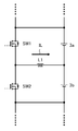
図2は、制御部の一実施例を示す図である。図3は、1組の放電する電池と充電する電池の関係を示す図である。
制御部1は、電圧計測部4a~4dの計測した電圧と、電流計測部5a~5cの計測した電流を取得する。
図2の判定部201は、直列に接続されている第1の電池と第2の電池の電圧を取得する。電圧は、第1の電池と第2の電池の電圧を均等にするための後述するパルス幅変調処理(電圧均等化処理)を開始する前の電圧計測部が計測した値である。
続いて、第1の電池の電圧と第2の電池の電圧の平均電圧を求め、平均電圧Vavgと第1の電池の電圧との電圧差または平均電圧と第2の電池の電圧との電圧差を求める。その後、電圧差が電圧計測部の電圧計測における許容誤差値により決まる第1の閾値以上か否かを判定する。
第1の閾値は、例えば、電圧計測部の許容誤差を用いて決めてもよいし、実験やシミュレーションにより電圧計測部の最大許容誤差を用いて決めてもよい。また、隣り合う電圧計測部それぞれの許容誤差を加算して第1の閾値としてもよい。例えば、電圧計測部4aの許容誤差と電圧計測部4bの許容誤差を加算して用いてもよい。また、第1の閾値は記憶部2に記憶しておくことが考えられる。
第1の電池の電圧が第2の電池の電圧より高い場合について、図3を用いて説明する。すなわち、電池3aが放電をしてコイルL1を介して電流ILを電池3bに供給して充電をする場合について説明する。
判定部201は、パルス幅変調処理の開始前の電池3a(第1の電池)の電圧V01と電池3b(第2の電池)の電圧V02を、それぞれの電圧計測部4a、4bから取得する。なお、電圧V01、V02には許容誤差が含まれている。
続いて、判定部201は、電池3aの電圧V01と電池3bの電圧V02の平均電圧Vavg=(V01+V02)/2を求める。続いて、平均電圧Vavgと電圧V01との電圧差V1=|V01-Vavg|または平均電圧Vavgと電圧V02との電圧差V2=|V02-Vavg|を求める。
その後、判定部201は電圧差V1または電圧差V2が第1の閾値より高いか否かを判定し、判定結果をパルス幅変調部202に送信する。
パルス幅変調部202は、電圧差V1または電圧差V2が第1の閾値より高い場合に、電圧均等化を行うパルス幅変調処理を実行する。また、電圧均等化を行うパルス幅変調処理中に、第1の電池の電圧Vn1と平均電圧Vavgとの電圧差Vs1=|Vn1-Vavg|と、第2の電池の電圧Vn2と平均電圧Vavgとの電圧差Vs2=|Vavg-Vn2|と、を求める。電圧差Vs1または電圧差Vs2が第1の閾値以下になると、パルス幅をデューティ50%に変更し、デューティ50%のパルス幅変調処理(電圧均等化処理)を実行する。なお、本例では最適値としてデューティ50%にすることを提案しているが、実際には電圧均等化装置の回路や周辺環境を加味してデューティを50%近傍に決めることが望ましい。
ここで、パルス幅をデューティ50%に変更する理由は、デューティ50%にすることで第1の電池の電圧と第2の電池の電圧との電圧差に応じて流れる成り行きの電流が、第1の電池の電圧と第2の電池の電圧との電圧差を0Vにするためである。
また、パルス幅変調部202はデューティ50%に変更してパルス幅変調処理を決められた時間だけ実行するとパルス幅変調処理を停止させる。決められた時間は、例えば、実験やシミュレーションにより電圧差Vs1または電圧差Vs2が第1の閾値になってから略ゼロになるまでの時間を求めて、記憶部2に記憶してもよい。
実施形態1の動作について説明する。
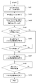
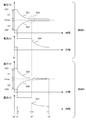
図4は、実施形態1における電圧均等化装置の動作の一実施例を示すフロー図である。図5は、実施形態1における電圧と電流の変化を示す図である。電池3aと電池3bの組について説明をする。図5の制御Aは定電流で電圧均等化をした後に定電圧の制御に移行する制御で、定電圧の制御においては電圧計測部4a、4bの計測した電圧値に基づいて制御を行う。図5の制御Bは定電流で電圧均等化をした後にデューティ50%のパルス幅変調処理に移行する制御で、電圧計測部4a、4bの計測した電圧値を参照しない制御を行う。
ステップS401では、制御部1が各電池3a、3bの電圧V01、V02を電圧計測部4a、4bから取得する。図5の制御Aと制御Bのパルス幅変調処理を開始する前である時間t0から時間t1より前の期間において電圧V01、V02を取得する。
ステップS402では、制御部1が取得した電圧V01、V02の平均電圧(実施形態1の目標電圧)Vavgを求める。
ステップS403では、制御部1が平均電圧Vavgと電圧V01との電圧差V1または平均電圧Vavgと電圧V02との電圧差V2を求める。
ステップS404では、制御部1が電圧差V1または電圧差V2が第1の閾値より高いか否かを判定し、第1の閾値より高い場合(Yes)にはステップS405に移行し、第1の閾値以下の場合(No)にはステップS407に移行する。
ステップS405では電圧差V1または電圧差V2が第1の閾値より高い場合に、制御部1が定電流で電圧均等化を行うパルス幅変調処理を開始する。図5の制御Aと制御Bの時間t1から定電流で電圧均等化を行うパルス幅変調処理を行う。図5の制御Aと制御Bにおいて、501、505は電池3aの電圧変化を示し、502、506は電池3bの電圧変化を示す。図5の制御Aの504は電流ILの電流変化を示し、図5の制御Bの507は電流ILの電流変化を示している。
ステップS406では、制御部1は現在の電池3aの電圧Vn1と平均電圧Vavgとの電圧差Vs1または現在の電池3bの電圧Vn2と平均電圧Vavgとの電圧差Vs2が第1の閾値以下か否かを判定する。電圧差Vs1または電圧差Vs2が第1の閾値以下の場合(Yes)にはステップS407に移行し、第1の閾値より高い場合(No)にはステップS406に移行する。
ステップS407で制御部1はデューティ50%でパルス幅変調処理を開始する。制御Bでは時間t2以降にデューティ50%でパルス幅変調処理を行うため、時間t3において電池3aと電池3bの電圧は均等になる。
図5の制御Bではデューティ50%でパルス幅変調処理を時間t2以降で行うため、時間t3で収束する。一方、図5の制御Aではデューティ50%でパルス幅変調処理を時間t2以降に行わず電圧計測部4a、4bの計測結果に基づいているため、破線範囲503に示すように時間t2以降になっても、求めた平均電圧Vavgまたは実際の平均電圧(目標電圧)に収束せずに、電池3a、3bの電圧はばらついてしまう。
ここで、ステップS402で求めた平均電圧Vavgは電圧計測部4a、4bの許容誤差を含んでいるため、実際の平均電圧(目標電圧)とは異なるが、デューティ50%でパルス幅変調処理を行うことで電圧Vn1、Vn2を目標電圧に近づけることができる。すなわち、高価な計測精度のよい電圧計測部を用いることなく、電池3aと電池3bの電圧を精度よく均等にできる。一方、制御Aでは電池3aと電池3bの電圧を精度よく均等にするには計測精度のよい電圧計測部が必要になる。
ステップS408では、制御部1がデューティ50%でパルス幅変調処理を開始してから決められた時間を経過したか否かを判定し、決められた時間を経過した場合(Yes)にはステップS409に移行する。決められた時間を経過していない場合に(No)にはステップS408においてデューティ50%でパルス幅変調処理を継続する。決められた時間は、図5の制御Bの時間t2と時間t3により表される期間である。
ステップS409では、制御部1はデューティ50%のパルス幅変調処理を終了する。
なお、実施形態1では定電流で電圧均等化を行うためのパルス幅変調処理を実行させているが定電流に限定されるものではなく、例えば、定電圧などを用いてよい。
実施形態1によれば、計測精度のよい高価な電圧計測部を用いなくても、電池電圧を均等にする精度を向上させることができるという効果を奏する。
実施形態2について説明する。
実施形態2の電圧均等化回路の制御部1は、電池3a~3dの電圧を均等にする時間を短縮する制御と、電池電圧を均等にする精度を向上させるパルス幅をデューティ50%に固定してパルス幅変調処理を行う。
図1の電池3a、3bの組、電池3b、3cの組、電池3c、3dの組について電圧均等化処理を行う際に、電圧計測部4a~4dで計測した電圧が均等になった時点で電圧均等化処理を停止させると、目標とする平均電圧Vavgから実際の電池3a~3dの電圧はずれてしまう。すなわち、それぞれの組の電池の平均電圧Vavgから、電池3a~3d各々の内部抵抗と電池3a~3d各々に流れる電流により決まる電圧だけ、電池3a~3d各々の電圧が均等になった時点から時間の経過とともにずれてしまう。そして、この電圧のずれを調整するために、繰り返し電圧均等化処理を行うと、電池3a~3dの電圧が均等になるまでに時間がかかる。そこで、電池3a~3dの内部抵抗を推定し、推定した内部抵抗に応じて調整電圧を求め、各組における放電をする電池と充電をする電池の目標電圧を、調整電圧を用いて後述する式1、式2に示す目標電圧にする。そして、各組における放電をする電池の電圧と充電をする電池の電圧の大小関係が逆転したのち、目標電圧になるまで定電流で電圧均等化を行う。電圧均等化を停止したのち推定した内部抵抗の緩和を利用して電池の電圧を均等にする。このような定電流で電圧均等化をすることで電池3a~3dの電圧を均等にする時間を短縮できる。
実施形態2の制御部1は、図6に示す調整電圧算出部601、目標電圧算出部602、判定部603、パルス幅変調部604などを有している。図6は、制御部の一実施例を示す図である。また、制御部1は定電流で電圧均等化をする際に電池3a~3dに一定の電流が供給されているかを監視する。
制御部1の調整電圧算出部601は、定電流で電圧均等化を行うパルス幅変調処理の開始前の第1の電池の開始電圧と定電流で電圧均等化を行うパルス幅変調処理の開始後の決められた時間経過後の第1の電池の電圧との差である第1の調整電圧を求める。また、定電流で電圧均等化を行うパルス幅変調処理の開始前の第2の電池の開始電圧と定電流で電圧均等化を行うパルス幅変調処理の開始後の決められた時間経過後の第2の電池の電圧との差である第2の調整電圧を求める。
電池3a(第1の電池)の開始電圧V01が電池3b(第2の電池)の開始電圧V02より高い場合、パルス幅変調処理の開始前の電池3aの開始電圧V01と決められた時間経過後の電池3aの電圧との差である調整電圧ΔV1を求める。パルス幅変調処理の開始前の電池3bの開始電圧V02と決められた時間経過後の電池3bの電圧との差である調整電圧ΔV2(第2の調整電圧)を求める。
制御部1の目標電圧算出部602は、第1の電池の電圧と第2の電池の電圧の平均から平均電圧を求め、平均電圧と第1の電池の調整電圧を用いて第1の電池の第1の目標電圧を求め、平均電圧と第2の電池の調整電圧を用いて第2の電池の第2の目標電圧を求める。
放電する電池3aと充電する電池3bの組の場合、電池3aの電圧と電池3bの電圧の平均から平均電圧Vavgを求める。そして、平均電圧Vavgと電池3aの調整電圧ΔV1を用いて電池3aの目標電圧Vt1を求め、平均電圧Vavgと電池3bの調整電圧ΔV2を用いて電池3bの目標電圧Vt2を求める。
放電をする電池の目標電圧Vt1と充電をする電池の目標電圧Vt2は式1、2により求める。
目標電圧Vt1=平均電圧Vavg-調整電圧ΔV1 式1
目標電圧Vt2=平均電圧Vavg+調整電圧ΔV2 式2
Vt1 :放電をする電池の目標電圧
Vt2 :充電をする電池の目標電圧
Vavg:組ごとの電池の平均電圧
ΔV1 :内部抵抗に応じて決まる電圧
ΔV2 :内部抵抗に応じて決まる電圧
制御部1の判定部603は、直列に接続されている第1の電池と第2の電池の電圧を取得する。続いて、第1の電池の電圧と第2の電池の電圧の平均電圧を求め、平均電圧と第1の電池の電圧との電圧差または平均電圧と第2の電池の電圧との電圧差を求める。
目標電圧Vt2=平均電圧Vavg+調整電圧ΔV2 式2
Vt1 :放電をする電池の目標電圧
Vt2 :充電をする電池の目標電圧
Vavg:組ごとの電池の平均電圧
ΔV1 :内部抵抗に応じて決まる電圧
ΔV2 :内部抵抗に応じて決まる電圧
制御部1の判定部603は、直列に接続されている第1の電池と第2の電池の電圧を取得する。続いて、第1の電池の電圧と第2の電池の電圧の平均電圧を求め、平均電圧と第1の電池の電圧との電圧差または平均電圧と第2の電池の電圧との電圧差を求める。
その後、電圧差が電圧計測部の電圧計測における許容誤差値により決まる第1の閾値以上か否かを判定する。第1の閾値は、例えば、電圧計測部の許容誤差を用いて決めてもよいし、実験やシミュレーションにより電圧計測部の最大許容誤差を求めて用いて決めてもよい。また、隣り合う電圧計測部それぞれの許容誤差を加算して第1の閾値としてもよい。例えば、電圧計測部4aの許容誤差と電圧計測部4bの許容誤差を加算して用いてもよい。また、第1の閾値は記憶部2に記憶しておくことが考えられる。
第1の電池の電圧が第2の電池の電圧より高い場合について、図3を用いて説明する。すなわち、電池3aが放電をしてコイルL1を介して電流ILを電池3bに供給して充電をする場合について説明する。
判定部603は、パルス幅変調処理の開始前の電池3a(第1の電池)の開始電圧V01と電池3b(第2の電池)の開始電圧V02をそれぞれの電圧計測部4a、4bから取得する。なお、開始電圧V01、V02には許容誤差が含まれている。
続いて、判定部603は、電池3aの開始電圧V01と電池3bの開始電圧V02の平均電圧Vavg=(V01+V02)/2を求める。続いて、平均電圧Vavgと開始電圧V01との電圧差V1=|V01-Vavg|または平均電圧Vavgと開始電圧V02との電圧差V2=|V02-Vavg|を求める。
その後、判定部603は電圧差V1または電圧差V2が第1の閾値より高いか否かを判定し、判定結果をパルス幅変調部604に送信する。
パルス幅変調部604は、電圧差V1または電圧差V2が第1の閾値より高い場合に、定電流で電圧均等化を行うパルス幅変調処理(電圧均等化処理)を実行する。続いて、制御部1のパルス幅変調部604は、第1の電池の電圧が第1の目標電圧になるか、または第2の電池の電圧が第2の目標電圧になると、パルス幅変調処理を停止する。
また、停止したのちに分極が解消していく際に、現在の電池3aの電圧Vn1と平均電圧との電圧差Vs1または現在の電池3bの電圧Vn2と平均電圧との電圧差Vs2が第1の閾値以下になるとパルス幅をデューティ50%に変更し、デューティ50%のパルス幅変調処理を実行する。
また、停止したのちに分極が解消するのを待ち、分極が解消されるとパルス幅をデューティ50%に変更し、デューティ50%のパルス幅変調処理を実行してもよい。
なお、本例では最適値としてデューティ50%にすることを提案しているが、実際には電圧均等化装置の回路や周辺環境を加味してデューティを50%近傍に決めることが望ましい。
また、パルス幅変調部604はデューティ50%に変更してパルス幅変調処理を決められた時間だけ実行するとパルス幅変調処理を停止させる。決められた時間は、例えば、実験やシミュレーションにより電圧差Vs1または電圧差Vs2が第1の閾値になってから略ゼロになるまでの時間を求めて、記憶部2に記憶してもよい。
実施形態2の動作について説明する。
図7は、実施形態2における電圧均等化装置の動作の一実施例を示すフロー図である。図8は、実施形態2における電圧と電流の変化を示す図である。図8の制御Cの806は電流ILの電流変化を示し、図8の制御Dの807は電流ILの電流変化を示している。
電池3aと電池3bの組について説明をする。実施形態1で説明したステップS401~S404と同じ処理を行う。ただし、実施形態2のステップS404では電圧差V1または電圧差V2が第1の閾値より高いか否かを判定し、第1の閾値より高い場合(Yes)にはステップS701に移行する。電圧差V1または電圧差V2が第1の閾値以下の場合(No)にはステップS706に移行する。
ステップS701では制御部1が定電流で電圧均等化を行うパルス幅変調処理を開始する。図8の制御C、Dの図の時間t1においてパルス幅変調処理を開始する。ステップS702で決められた時間を経過した後、制御部1が調整電圧ΔV1、ΔV2を求める。
ステップS703では、電池3aの現在の計測した電圧Vn1が目標電圧Vt1(=平均電圧Vavg-調整電圧ΔV1)になったか、または電池3bの現在の計測した電圧Vn2が目標電圧Vt2(=平均電圧Vavg+調整電圧ΔV2)になったか、制御部1が判定をする。電圧Vn1が目標電圧Vt1になるかまたは電圧Vn2が目標電圧Vt2になる場合(Yes)にはステップS704に移行する。電圧Vn1が目標電圧Vt1にならず、かつ電圧Vn2が目標電圧Vt2にならない場合(No)にはステップS703では定電流で電圧均等化を行うパルス幅変調処理を継続する。図8の制御C、Dの図の時間t1からパルス幅変調処理を開始する。
ステップS704では、制御部1がパルス幅変調処理を終了し、ステップS705では制御部1が分極解消を待つ。図8の制御C、Dの図の時間t3でパルス幅変調処理を終了し、図8の制御Dの図の時間t4まで分極解消を待つ。次にステップS706に移行する。
分極解消を待つとは、停止したのちに分極が解消していく際に、現在の電池3aの電圧Vn1と平均電圧との電圧差Vs1または現在の電池3bの電圧Vn2と平均電圧との電圧差Vs2が第1の閾値以下になるとパルス幅をデューティ50%に変更し、デューティ50%のパルス幅変調処理を実行する。
また、停止したのちに分極が解消するのを待ち、分極が解消されるとパルス幅をデューティ50%に変更し、デューティ50%のパルス幅変調処理を実行してもよい。
図8の制御Cでは、図の803に示すように時間t4以降になっても、平均電圧Vavgまたは実際の平均電圧(目標電圧)に収束せずに、電池3a、3bの電圧はばらついてしまう。
ステップS706で制御部1はデューティ50%でパルス幅変調処理を開始する。制御Dの図では時間t4以降にデューティ50%でパルス幅変調処理を行うため、時間t5において電池3aと電池3bの電圧は均等になる。ここで、ステップS402で求めた平均電圧Vavgは電圧計測部4a、4bの許容誤差を含んでいるため、実際の平均電圧(目標電圧)とは異なるが、デューティ50%でパルス幅変調処理を行うことで電圧Vn1、Vn2を目標電圧に近づけることができる。すなわち、計測精度のよい高価な電圧計測部を用いることなく、電池3aと電池3bの電圧を精度よく均等にできる。一方、制御Cでは電池3aと電池3bの電圧を精度よく均等にするには計測精度のよい電圧計測部が必要になる。
ステップS707では、制御部1がデューティ50%でパルス幅変調処理を開始してから決められた時間を経過したか否かを判定し、決められた時間を経過した場合(Yes)にはステップS708に移行する。決められた時間を経過していない場合に(No)にはステップS707においてデューティ50%でパルス幅変調処理を継続する。決められた時間は、図8の制御Dの図の時間t4と時間t5により表される期間である。
ステップS708では、制御部1はデューティ50%のパルス幅変調処理を終了する。
なお、実施形態2では定電流で電圧均等化を行うためのパルス幅変調処理を実行させているが定電流に限定されるものではない。
実施形態2によれば、計測精度のよい高価な電圧計測部を用いなくても、電池電圧を均等にする精度を向上させることができるという効果を奏する。
また、実施形態2によれば電池の電圧を均等にする時間を短縮でき、さらに電池電圧を均等にする精度を向上させることができるという効果を奏する。
また、本発明は、実施形態1、2に限定されるものでなく、本発明の要旨を逸脱しない範囲内で種々の改良、変更が可能である。
実施形態3について説明する。
3個以上の電池が直列接続された組電池に対して、従来のスイッチングコンバータによる電圧均等化処理(定電流充電でのパルス幅変調処理)は、隣接する2つの電池同士で電圧を比較し、その比較結果により電荷移動の方向を決定し、決定した方向に電荷を移動するようにスイッチングコンバータを制御している。そのため、周辺の電池の電圧変動の影響を受け、隣接する電池とで電圧の高低が反転を繰り返したり、電荷の無駄な往復移動を繰り返したりするなど、全体として効率良く電荷移動が行われず、電圧均等化処理に多くの時間を要する。
実施形態3では、電圧均等化処理の動作効率を向上させ、電圧均等化処理に要する時間の短縮化を図ることができる電圧均等化装置および電圧均等化方法を提供するとともに、実施形態1、2の技術を、その電圧均等化装置および電圧均等化方法に適用する。
実施形態3によれば、電圧均等化処理のための電荷の移動方向が、周辺の電池の電圧変動に影響されることなく、一意に決定されるため、隣接する電池で電荷の無駄な往復移動を繰り返すことがなく、電荷の移動量を最少に抑え、効率良く電圧均等化処理を行うことができる。さらに、電池電圧の均等化効率の向上および電圧均等化処理に要する時間の短縮化が可能になる。
また、実施形態1、2で説明したデューティ50%のパルス幅変調処理を適用することで、計測精度のよい高価な電圧計測部を用いなくても、電池電圧を均等にする精度を向上させることができる。
また、実施形態2で説明した各電池の平均電圧と調整電圧により決まる目標電圧になるまでパルス幅変調処理を行うことと、実施形態1、2で説明したデューティ50%のパルス幅変調処理と、を用いて、さらに電池の電圧を均等にする時間を短縮でき、電池電圧を均等にする精度を向上させることができる。
以下の実施形態3では、5個の直列接続の電池に対する電圧均等化処理の動作例について説明するが、これに限定されるものではなく、少なくとも3個以上の直列に接続された電池に対する電圧均等化処理に適用が可能である。
実施形態3の構成について説明をする。
図9は、実施形態3における電圧均等化装置の一実施例を示す図である。図9の電圧均等化装置は、スイッチングコンバータSC12、SC23、SC34、SC45と制御部1を備える。制御部1は、平均電圧算出部901、比較部902、パルス幅変調部903および判定部904を備える。
スイッチングコンバータSC12は、スイッチSW12、SW21、ダイオードD21、D12およびコイルL12を有し、コイルL12を介して電池Ce1、Ce2の電荷移動を行う。スイッチングコンバータSC23は、スイッチSW23、SW32、ダイオードD32、D23およびコイルL23を有し、コイルL23を介して電池Ce2、Ce3の電荷移動を行う。スイッチングコンバータSC34は、スイッチSW34、SW43、ダイオードD43、D34およびコイルL34を有し、コイルL34を介して電池Ce3、Ce4の電荷移動を行う。スイッチングコンバータSC45は、スイッチSW45、SW54、ダイオードD54、D45およびコイルL45を有し、コイルL45を介して電池Ce4、Ce5の電荷移動を行う。
平均電圧算出部901、比較部902およびパルス幅変調部903は、スイッチングコンバータSC12、SC23、SC34、SC45のコイル(インダクタ)L12、L23、L34、L45を境にして、全電池を2つのグループに分け、2つのグループの平均電圧を比較して電荷の移動方向を決定し、該移動方向に電荷を移動させる制御に用いられる。
平均電圧算出部901は、各電池Ce1、Ce2、Ce3、Ce4、Ce5の電圧計測部(図示省略)から各電池Ce1、Ce2、Ce3、Ce4、Ce5の電池電圧を入力する。平均電圧算出部901は、直列接続された少なくとも3個の電池を、該直列接続の列順を維持したまま、順次、2つのグループに分け、各グループ内の電池の平均電圧を算出する。平均電圧の算出については後述する図10のA~Dを用いて説明する。ただし、グループ分けは予め記憶部に記憶しておいてもよい。
比較部902は、平均電圧算出部901で計算した2つのグループの平均電圧を比較する。
パルス幅変調部903は、比較部902の比較結果を基に、平均電圧の高いグループの境界に位置する電池から、平均電圧の低いグループの境界に位置する隣接する電池へ、電荷を移動させるよう、スイッチのオン/オフ制御を行う。例えば、スイッチングコンバータSC12、SC23、SC34、SC45それぞれに対して、電荷の移動方向と移動量に基づいてパルス幅を決定し、電流スイッチのオン/オフ制御をする。
また、パルス幅変調部903はデューティ50%のパルス幅変調処理を実行する。
判定部904は、電荷移動を終了して停止しているスイッチングコンバータを検出し、停止している2つのスイッチングコンバータがある場合で、且つ停止している2つのスイッチングコンバータが共通して制御している電池があると判定された場合に、対象のスイッチングコンバータにデューティ50%のパルス幅変調処理をさせる指示を、パルス幅変調部903に出力する。対象のスイッチングコンバータは、例えば、図9のスイッチングコンバータSC23がパルス幅変調処理中で、スイッチングコンバータSC34、SC45が停止している場合、電池Ce4と電池Ce4に接続される電池Ce5の間では電荷の移動がされていないので、スイッチングコンバータSC45を対象とする。なお、電池Ce3はスイッチングコンバータSC23により電荷の移動がされているので、スイッチングコンバータSC34は対象のスイッチングコンバータにはならない。
電池のグループに分けと、グループの平均電圧について説明をする。
図10は、電池を2グループに分けたときの平均電圧の一実施例を示す図である。グループ分けは、直列接続された5個の電池Ce1~Ce5を、該直列接続の列順を維持したまま、順々に、2つのグループに分けたことを示している。また、各グループ内の電池の平均電圧を示している。
図10では、電池全体の平均電圧Vavgを基準電圧とし、電池Ce1は平均電圧Vavgに対して-1V、電池Ce2は平均電圧Vavgに対して-2V、電池Ce3は平均電圧Vavgに対して+1V、電池Ce4は平均電圧Vavgに対して+3V、電池Ce5は平均電圧Vavgに対して-1Vであったとする。
図10のAは、電池Ce1のみのグループと、電池Ce2~Ce5のグループとに分けたとき、電池Ce1のみのグループの平均電圧Vavg-1V、電池Ce2~Ce5のグループの平均電圧Vavg+0.25Vと計算された例を示している。この場合、グループの境界は電池Ce1と電池Ce2との間で、電池Ce1と電池Ce2はグループの境界に位置する隣接する電池である。
図10のBは、電池Ce1~Ce2のグループと、電池Ce3~Ce5のグループとに分けたとき、電池Ce1~Ce2のグループの平均電圧Vavg-1.5V、電池Ce3~Ce5のグループの平均電圧Vavg+1Vと計算された例を示している。この場合、グループの境界は電池Ce2と電池Ce3との間で、電池Ce2と電池Ce3はグループの境界に位置する隣接する電池でもある。
図10のCは、電池Ce1~Ce3のグループと、電池Ce4~Ce5のグループとに分けたとき、電池Ce1~Ce3のグループの平均電圧Vavg-0.67V、電池Ce4~Ce5のグループの平均電圧Vavg+1Vと計算された例を示している。この場合、グループの境界は電池Ce3と電池Ce4との間で、電池Ce3と電池Ce4はグループの境界に位置する隣接する電池でもある。
図10のDは、電池Ce1~Ce4のグループと、電池Ce5のみのグループとに分けたとき、電池Ce1~Ce4のグループの平均電圧Vavg+0.25V、電池Ce5のみのグループの平均電圧Vavg-1Vと計算された例を示している。この場合、グループの境界は電池Ce4と電池Ce5との間で、電池Ce4と電池Ce5はグループの境界に位置する隣接する電池でもある。
電荷移動の処理について説明する。
電池Ce1と電池Ce2との間には、スイッチングコンバータSC12が介在し、電池Ce2と電池Ce3との間には、スイッチングコンバータSC23が介在し、電池Ce3と電池Ce4との間には、スイッチングコンバータSC34が介在し、電池Ce4と電池Ce5との間には、スイッチングコンバータSC45が介在する。
一例としてスイッチングコンバータSC23に注目すると、図10のBに示すように、電池Ce1と電池Ce2の平均電圧-1.5Vと、電池Ce3~Ce5の平均電圧+1Vとを比較し、平均電圧の低い方のグループの電池Ce2(平均電圧の低いグループの境界に位置する隣接する電池)へ、平均電圧の高い方のグループの電池Ce3(平均電圧の高いグループの境界に位置する電池)から電流をスイッチングコンバータSC23により流す。
スイッチングコンバータSC23による電流の流出/流入は、電池Ce1と電池Ce2の平均電圧が電池Ce3~Ce5の平均電圧と等しくなったとき又はそれを超えたときに停止する。
同様に、その他のスイッチングコンバータSC12、SC34、SC45についても、両側のグループの電池の平均電圧を基に電荷の移動方向を決定する。各スイッチングコンバータSC12、SC23、SC34、SC45は、同時に又は並行して各スイッチを駆動する構成とすることができる。
このとき、各スイッチングコンバータの動作は、他のスイッチングコンバータの動作による影響を受けない。例えば、スイッチングコンバータSC23に着目すると、スイッチングコンバータSC23の動作は、電池Ce2と電池Ce3との間だけの電荷移動であり、この電荷移動によって、他のグループ分けによるグループの平均電圧は変化しないからである。
すなわち、電池Ce2と電池Ce3との間の電荷移動だけでは、図10のAのグループ分けによる電池Ce2~Ce5のグループでは、同一グループ内の電池間での電荷移動となるため、電池Ce2~Ce5のグループの平均電圧に変化は生じない。同様に、図10のCのグループ分けによる電池Ce1~Ce3のグループでも、同一グループ内の電池間での電荷移動となるため、電池Ce1~Ce3のグループの平均電圧に変化は生じない。また、図10のDのグループ分けによる電池Ce1~Ce4のグループでも、同一グループ内の電池間での電荷移動となるため、電池Ce1~Ce4のグループの平均電圧に変化は生じない。
また、他のスイッチングコンバータSC12、SC34、SC45による電荷移動も、スイッチングコンバータSC23の動作に影響を与えない。すなわち、スイッチングコンバータSC12による電荷移動は、電池Ce1と電池Ce2との間だけの電荷移動であり、スイッチングコンバータSC34による電荷移動は、電池Ce3と電池Ce4との間だけの電荷移動であり、スイッチングコンバータSC45による電荷移動は、電池Ce4と電池Ce5との間だけの電荷移動であるため、電池Ce1と電池Ce2のグループと、電池Ce3~電池Ce5のグループの各平均電圧に影響を与えない。
従って、スイッチングコンバータSC12、SC23、SC34、SC45を、独立に駆動することができ、制御部1は、各スイッチングコンバータSC12、SC23、SC34、SC45を同時に又は並行して駆動することにより、電池バランスの動作時間を短縮することが可能となる。
なお、図10のA~Dに示したように2つのグループの境界に位置する隣接する2つの電池と、2つの電池に対応するスイッチングコンバータと、を関連付けて予め記憶部に記憶しておく。例えば図10のAの場合、電池Ce1のグループと電池Ce2~5のグループの境界に位置する隣接する2つの電池Ce1と電池Ce2とスイッチングコンバータSC12とを関連付けて予め記憶部に記憶しておく。
実施形態3の動作について説明する。
図11は、実施形態3における電圧均等化の動作の一実施例を示すフロー図である。図11は、直列接続された電池のm番目とm+1番目の列順の隣接電池に対する電荷移動の動作例を示している。なお、電池の全個数はn個であるとする。なお、図11の例は図9のスイッチングコンバータSC12、SC23、SC34、SC45それぞれを同時に又は並行して動作させることが可能な制御部の動作を示している。例えば、スイッチングコンバータSC12、SC23、SC34、SC45それぞれに対して4つのCPUを用意して同時に又は並行して動作させてもよい。また、スイッチングコンバータSC12、SC23、SC34、SC45に対してマルチコアCPUまたはプログラマブルなデバイスなどを用意して同時に又は並行して動作させてもよい。
ステップS1101では、制御部1が第1番目から第m番目までの電池のグループの平均電圧Avmと、m+1番目からn番目までの電池のグループの平均電圧Avm+1とを算出する。
ステップS1102では、制御部1がAvmとAvm+1との大小比較をし、Avm>Avm+1の場合(Yes)にはステップS1103に移行し、Avm<Avm+1の場合(No)にはステップS1106に移行する。なお、Avm=Avm+1の場合には、電荷の移動をしない。
ステップS1103では、比較の結果、AvmがAvm+1より大きい場合、m番目の電池からm+1番目の電池へ電荷を移動させるよう、制御部1がスイッチのオン/オフ制御を行う。
ステップS1104では、制御部1が電荷移動後のAvmとAvm+1とを算出する。
ステップS1105では、制御部1がAvmとAvm+1との大小比較をし、Avm>Avm+1の場合(Yes)にはステップS1103に移行し、Avm≦Avm+1の場合(No)には処理を終了する。
ステップS1106では、比較の結果、AvmがAvm+1より小さい場合、m+1番目の電池からm番目の電池へ電荷を移動させるよう、制御部1がスイッチのオン/オフ制御を行う。
ステップS1107では、制御部1が電荷移動後のAvmとAvm+1とを算出する。
ステップS1108では、制御部1がAvmとAvm+1との大小比較をし、Avm<Avm+1の場合(Yes)にはステップS1106に移行し、Avm≧Avm+1の場合(No)には処理を終了する。
図12は、目標電圧になるまで電荷移動をする場合の動作を説明するための図である。
図10のAの電池Ce1のみのグループと電池Ce2~Ce5のグループの場合、電池Ce1のみのグループの平均電圧Vavg-1V(Avm)は電池Ce2~Ce5のグループの平均電圧Vavg+0.25V(Avm+1)より小さいので、ステップS1106に移行する。そうすると、グループの境界は電池Ce1と電池Ce2との間であるから、電池Ce2から隣接する電池Ce1へ電荷の移動をさせる制御を制御部1がスイッチングコンバータSC12に開始させる。
図10のBの電池Ce1~Ce2のグループと、電池Ce3~Ce5のグループの場合、電池Ce1~Ce2のグループの平均電圧Vavg-1.5V(Avm)は電池Ce3~Ce5のグループの平均電圧Vavg+1V(Avm+1)より小さいので、ステップS1106に移行する。そうすると、グループの境界は電池Ce2と電池Ce3との間であるから、電池Ce3から隣接する電池Ce2へ電荷の移動をさせる制御を制御部1がスイッチングコンバータSC23に開始させる。
図10のCの電池Ce1~Ce3のグループと、電池Ce4~Ce5のグループの場合、電池Ce1~Ce3のグループの平均電圧Vavg-0.67V(Avm)は電池Ce4~Ce5のグループの平均電圧Vavg+1V(Avm+1)より小さいので、ステップS1106に移行する。そうすると、グループの境界は電池Ce3と電池Ce4との間であるから、電池Ce4から隣接する電池Ce3へ電荷の移動をさせる制御を制御部1がスイッチングコンバータSC34に開始させる。
図10のDの電池Ce1~Ce4のグループと、電池Ce5のみのグループの場合、電池Ce1~Ce4のグループの平均電圧Vavg+0.25V(Avm)は電池Ce5のみのグループの平均電圧Vavg-1V(Avm+1)より小さいので、ステップS1103に移行する。そうすると、グループの境界は電池Ce4と電池Ce5との間であるから、電池Ce4から隣接する電池Ce5へ電荷の移動をさせる制御を制御部1がスイッチングコンバータSC45に開始させる。
ステップS1103に移行した場合、ステップS1105の条件を満たしているか否かを判定する。ステップS1106に移行した場合、ステップS1108の条件を満たしているか否かを判定する。
図10のAの電池Ce1のみのグループと電池Ce2~Ce5のグループの場合、図12の時間time1でステップS1108の条件を満たさないので、スイッチングコンバータSC12を停止させる。すなわち、電池Ce1のみのグループの平均電圧(Avm)は電池Ce2~Ce5のグループの平均電圧(Avm+1)と等しくなるので、スイッチングコンバータSC12の電荷移動の制御を停止させる。
図10のBの電池Ce1~Ce2のグループと、電池Ce3~Ce5のグループの場合、図12の時間time1でステップS1108の条件を満たすので、スイッチングコンバータSC23を停止させない。すなわち、電池Ce1~Ce2のグループの平均電圧Vavg-1.0V(Avm)は電池Ce3~Ce5のグループの平均電圧Vavg+1.0V(Avm+1)より小さいので、スイッチングコンバータSC23の電荷移動の制御を継続させる。
図10のCの電池Ce1~Ce3のグループと、電池Ce4~Ce5のグループの場合、図12の時間time1でステップS1108の条件を満たすので、スイッチングコンバータSC34を停止させない。すなわち、電池Ce1~Ce3のグループの平均電圧Vavg-0.33V(Avm)は電池Ce4~Ce5のグループの平均電圧Vavg+0.5V(Avm+1)より小さいので、スイッチングコンバータSC34の電荷移動の制御を継続させる。
図10のDの電池Ce1~Ce4のグループと、電池Ce5のみのグループの場合、図12の時間time1でステップS1105の条件を満たさないので、スイッチングコンバータSC45を停止させる。すなわち、電池Ce1~Ce4のグループの平均電圧(Avm)は電池Ce5のみのグループの平均電圧(Avm+1)と等しくなるので、スイッチングコンバータSC45の電荷移動の制御を停止させる。
図12の時間time1までの期間において、電池Ce2の電圧に変化がないのは、一方で電池Ce2から電池Ce1に電荷移動させているが、他方で電池Ce3から電池Ce2に電荷移動がされているためである。同じように、電池Ce3の電圧に変化がないのは、一方で電池Ce3から電池Ce2に電荷移動させているが、他方で電池Ce4から電池Ce3に電荷移動がされているためである。
図12の時間time1から時間time2になるまでの期間について説明する。
図12の時間time0から時間time1の期間においてスイッチングコンバータSC23、SC34が電荷移動の制御を継続している。
図10のBの電池Ce1~Ce2のグループと、電池Ce3~Ce5のグループの場合、図12の時間time2でステップS1108の条件を満たすので、スイッチングコンバータSC23を停止させない。すなわち、電池Ce1~Ce2のグループの平均電圧Vavg-0.5V(Avm)は電池Ce3~Ce5のグループの平均電圧Vavg+0.33V(Avm+1)より小さいので、スイッチングコンバータSC23の電荷移動の制御を継続させる。
図10のCの電池Ce1~Ce3のグループと、電池Ce4~Ce5のグループの場合、図12の時間time2でステップS1108の条件を満たさないので、スイッチングコンバータSC34を停止させる。すなわち、電池Ce1~Ce3のグループの平均電圧(Avm)は電池Ce4~Ce5のグループの平均電圧(Avm+1)と等しくなるので、スイッチングコンバータSC34の電荷移動の制御を停止させる。
図12の時間time1から時間time2になるまでの期間において、電池Ce3の電圧に変化がないのは、一方で電池Ce3から電池Ce2に電荷移動させているが、他方で電池Ce4から電池Ce3に電荷移動がされているためである。
図12の時間time2から時間time3になるまでの期間について説明する。
図12の時間time1から時間time2においてスイッチングコンバータSC23だけが電荷移動の制御を継続している。
図10のBの電池Ce1~Ce2のグループと、電池Ce3~Ce5のグループの場合、図12の時間time3でステップS1108の条件を満たさいので、スイッチングコンバータSC23を停止させる。すなわち、電池Ce1~Ce2のグループの平均電圧(Avm)は電池Ce3~Ce5のグループの平均電圧(Avm+1)と等しいので、スイッチングコンバータSC23の電荷移動の制御を停止させる。
このように、制御することで、隣接する電池で電荷の無駄な往復移動を繰り返すことがなく、電荷の移動量を最少に抑え、効率良く電圧均等化処理を行うことができる。さらに、電池電圧の均等化効率の向上および電圧均等化処理に要する時間の短縮化が可能になる。
デューティ50%のパルス幅変調処理への切り替える場合について説明する。
図13は、デューティ50%のパルス幅変調処理への切り替える動作の一実施例を示すフロー図である。ステップS1301では、制御部1が電荷移動を終了して停止しているスイッチングコンバータを検出する。電荷移動を終了して停止しているスイッチングコンバータを検出した場合(Yes)にはステップS1302に移行し、検出しない場合(No)にはいずれかのスイッチングコンバータが停止するのを待つ。
ステップS1302では、制御部1がステップS1301で検出したスイッチングコンバータとで共通の電池を有する停止しているスイッチングコンバータがあるかを検出する。ただし、既にデューティ50%のパルス幅変調処理をしているスイッチングコンバータまたはデューティ50%のパルス幅変調処理を終了したスイッチングコンバータは、ステップS1302の検出する対象から外す。共通の電池を有する停止しているスイッチングコンバータがある場合(Yes)にはステップS1303に移行する。共通の電池を有する停止しているスイッチングコンバータがない場合(No)にはステップS1301に移行する。
ステップS1303では、制御部1が対象となるスイッチングコンバータに、決められた時間デューティ50%でパルス幅変調処理をさせる指示をする。
ステップS1304では、制御部1がすべてのスイッチングコンバータが停止をしているか否かを検出し、すべてのスイッチングコンバータが停止している場合(Yes)にはステップS1305に移行する。停止していない場合(No)にはステップS1301に移行する。
ステップS1305では、制御部1が停止をした最後のスイッチングコンバータに、決められた時間デューティ50%でパルス幅変調処理をさせる指示をする。
このように、停止している2つのスイッチングコンバータがある場合で、且つ2つのスイッチングコンバータが共通して制御している電池があると判定された場合に、デューティ50%のパルス幅変調処理をさせる指示を、パルス幅変調部903に出力する。
図12の例では、時間time2以降からスイッチングコンバータSC45がデューティ50%のパルス幅変調処理を決められた時間行う。また、時間time3でスイッチングコンバータSC12、SC23、SC34がデューティ50%のパルス幅変調処理を決められた時間行う。
このように制御することで、計測精度のよい高価な電圧計測部を用いなくても、電池電圧を均等にする精度を向上させることができる。
なお、本発明は、以上に述べた実施の形態に限定されるものではなく、本発明の要旨を逸脱しない範囲内で種々の構成または実施形態を取ることができる。
例えば、実施形態3で、2つのグループの平均電圧を比較したが、一方のグループの平均電圧と全電池の平均電圧を比較しても良い。この場合、比較部902は、2つのグループのうちの一方のグループの平均電圧と全電池の平均電圧とを比較する。パルス幅変調部903は、比較部の比較結果を基に、一方のグループの平均電圧が全電池の平均電圧より高いときは、一方のグループの境界に位置する電池から、他方のグループの境界に位置する隣接電池へ電荷を移動させ、一方のグループの平均電圧が全セルの平均電圧より低いときは、一方のグループの境界に位置する電池へ、他方のグループの境界に位置する隣接電池から電荷を移動させるよう制御を行う。
また、実施形態3でステップS1301~1303を省き、全てのスイッチングコンバータが停止してから(時間time3)、全てのスイッチングコンバータにデューティ50%のパルス幅変調処理をさせても良い。
Claims (9)
- 複数の電池が直列に接続される組電池と、
前記電池の負極端子と前記電池に隣接する電池の正極端子とに一方の端子が接続されるインダクタと、
前記電池の正極端子と前記インダクタの他方の端子との間に接続される一方のスイッチと、
前記電池に隣接する電池の負極端子と前記インダクタの他方の端子との間に接続される他方のスイッチと、
前記電池それぞれの電圧を計測する電圧計測部と、
前記一方のスイッチと前記他方のスイッチを制御して電圧均等化を行うためのパルス幅変調処理を実行させるパルス幅変調部と、
前記電池の平均電圧を求め、前記平均電圧と前記電池との電圧差を求め、前記電圧差が電圧計測部の許容誤差値により決まる第1の閾値より高いか否かを判定する判定部と、
を備え、
前記パルス幅変調部は、
前記電圧差が、前記第1の閾値より高い場合に、電圧均等化を行うパルス幅変調処理を実行し、前記電圧差が、前記第1の閾値以下になると、パルス幅をデューティ50%に変更してパルス幅変調処理を実行させる、
ことを特徴とする電圧均等化装置。 - 前記パルス幅変調部は、定電流で電圧均等化を行うためのパルス幅変調処理を実行させることを特徴とする請求項1に記載の電圧均等化装置。
- 決められた時間を経過するとパルス幅がデューティ50%の前記パルス幅変調処理を停止させる、ことを特徴とする請求項1または2に記載の電圧均等化装置。
- 複数の電池が直列に接続される組電池と、
前記電池の負極端子と前記電池に隣接する電池の正極端子とに一方の端子が接続されるインダクタと、
前記電池の正極端子と前記インダクタの他方の端子との間に接続される一方のスイッチと、
前記電池に隣接する電池の負極端子と前記インダクタの他方の端子との間に接続される他方のスイッチと、
前記電池それぞれの電圧を計測する電圧計測部と、
前記一方のスイッチと前記他方のスイッチを制御して電圧均等化を行うためのパルス幅変調処理を実行させるパルス幅変調部と、
前記パルス幅変調処理の開始前の前記電池の開始電圧と決められた時間経過後の前記電池の電圧との差である調整電圧を求める調整電圧算出部と、
前記電池の平均電圧を求め、前記平均電圧と前記電池の調整電圧を用いて前記電池の目標電圧を求める目標電圧算出部と、
前記電池の平均電圧を求め、前記平均電圧と前記電池との電圧差を求め、前記電圧差が電圧計測部の許容誤差値により決まる第1の閾値より高いか否かを判定する判定部と、
を備え、
前記パルス幅変調部は、
前記電圧差が、前記第1の閾値より高い場合に、前記パルス幅変調処理を実行し、前記電池の電圧が前記目標電圧になると、前記パルス幅変調処理を停止し、停止したのちに、パルス幅をデューティ50%に変更してパルス幅変調処理を実行させる、
ことを特徴とする電圧均等化装置。 - 決められた時間を経過するとパルス幅がデューティ50%の前記パルス幅変調処理を停止させる、ことを特徴とする請求項4に記載の電圧均等化装置。
- 直列に接続される前記電池を、該直列接続の列順を維持したまま、2つのグループに分け、前記2つのグループそれぞれの平均電圧を算出する平均電圧算出部と、
前記2つのグループの平均電圧を比較する比較部と、
前記比較部の比較結果を基に、前記平均電圧の高いグループの境界に位置する電池から、前記平均電圧の低いグループの境界に位置する前記電池に隣接する電池へ、電荷を移動させるよう、前記一方のスイッチと前記他方のスイッチの制御を行うパルス幅変調部と、
を備える、
を特徴とする請求項1~5のいずれか1つに記載の電圧均等化装置。 - 直列に接続される前記電池を、該直列接続の列順を維持したまま、2つのグループに分け、前記2つのグループそれぞれの平均電圧を算出する平均電圧算出部と、
前記2つのグループのうちの一方のグループの平均電圧と全電池の平均電圧とを比較する比較部と、
前記比較部の比較結果を基に、一方のグループの平均電圧が全電池の平均電圧より高いときは、該一方のグループの境界に位置する電池から、他方のグループの境界に位置する隣接電池へ電荷を移動させ、前記一方のグループの平均電圧が全セルの平均電圧より低いときは、該一方のグループの境界に位置する電池へ、前記他方のグループの境界に位置する隣接電池から電荷を移動させるよう、前記一方のスイッチと前記他方のスイッチの制御を行うパルス幅変調部と、
を備える、
ことを特徴とする請求項1~5のいずれか1つに記載の電圧均等化装置。 - 複数の電池が直列に接続される組電池と、前記電池の負極端子と前記電池に隣接する電池の正極端子とに一方の端子が接続されるインダクタと、前記電池の正極端子と前記インダクタの他方の端子との間に接続される一方のスイッチと、前記電池に隣接する電池の負極端子と前記インダクタの他方の端子との間に接続される他方のスイッチと、前記電池それぞれの電圧を計測する電圧計測部と、前記一方のスイッチと前記他方のスイッチを制御して電圧均等化を行うためのパルス幅変調処理を実行させる制御部と、を有する電圧均等化回路の電圧均等化方法であって、
制御部は、
前記電池の平均電圧を求め、前記平均電圧と前記電池との電圧差を求め、前記電圧差が電圧計測部の許容誤差値により決まる第1の閾値より高いか否かを判定し、
前記電圧差が、前記第1の閾値より高い場合に、電圧均等化を行うパルス幅変調処理を実行し、
前記電圧差が、前記第1の閾値以下になると、パルス幅をデューティ50%に変更してパルス幅変調処理を実行させる、
ことを特徴とする電圧均等化方法。 - 複数の電池が直列に接続される組電池と、前記電池の負極端子と前記電池に隣接する電池の正極端子とに一方の端子が接続されるインダクタと、前記電池の正極端子と前記インダクタの他方の端子との間に接続される一方のスイッチと、前記電池に隣接する電池の負極端子と前記インダクタの他方の端子との間に接続される他方のスイッチと、前記一方のスイッチと前記他方のスイッチを制御して電圧均等化を行うためのパルス幅変調処理を実行させる制御部と、を有する電圧均等化回路の電圧均等化方法であって、
制御部は、
前記電池の平均電圧を求め、前記平均電圧と前記電池との電圧差を求め、前記電圧差が電圧計測部の許容誤差値により決まる第1の閾値より高いか否かを判定し、
前記電圧差が、前記第1の閾値より高い場合に、前記パルス幅変調処理を実行し、
前記パルス幅変調処理の開始前の前記電池の開始電圧と決められた時間経過後の前記電池の電圧との差である調整電圧を求め、
前記電池の平均電圧を求め、前記平均電圧と前記電池の調整電圧を用いて前記電池の目標電圧を求め、
前記電池の電圧が前記目標電圧になると、前記パルス幅変調処理を停止し、
停止したのちに、パルス幅をデューティ50%に変更してパルス幅変調処理を実行させる、
ことを特徴とする電圧均等化方法。
Applications Claiming Priority (2)
| Application Number | Priority Date | Filing Date | Title |
|---|---|---|---|
| JP2012-221796 | 2012-10-04 | ||
| JP2012221796 | 2012-10-04 |
Publications (1)
| Publication Number | Publication Date |
|---|---|
| WO2014054504A1 true WO2014054504A1 (ja) | 2014-04-10 |
Family
ID=50434832
Family Applications (1)
| Application Number | Title | Priority Date | Filing Date |
|---|---|---|---|
| PCT/JP2013/076126 Ceased WO2014054504A1 (ja) | 2012-10-04 | 2013-09-26 | 電圧均等化装置および電圧均等化方法 |
Country Status (1)
| Country | Link |
|---|---|
| WO (1) | WO2014054504A1 (ja) |
Citations (1)
| Publication number | Priority date | Publication date | Assignee | Title |
|---|---|---|---|---|
| JP2003158828A (ja) * | 2001-11-20 | 2003-05-30 | Japan Storage Battery Co Ltd | 組電池用の電圧レベル均等化装置 |
-
2013
- 2013-09-26 WO PCT/JP2013/076126 patent/WO2014054504A1/ja not_active Ceased
Patent Citations (1)
| Publication number | Priority date | Publication date | Assignee | Title |
|---|---|---|---|---|
| JP2003158828A (ja) * | 2001-11-20 | 2003-05-30 | Japan Storage Battery Co Ltd | 組電池用の電圧レベル均等化装置 |
Similar Documents
| Publication | Publication Date | Title |
|---|---|---|
| CN103094956B (zh) | 用于电池均衡的装置和方法 | |
| CN111656644B (zh) | 对电池充电的基于非线性伏安法的方法和实现该方法的快速充电系统 | |
| JP5454632B2 (ja) | 充放電制御装置 | |
| US10554055B2 (en) | Battery system and method for controlling the same | |
| US10559963B2 (en) | Balance correction apparatus and electric storage system | |
| JP5975169B2 (ja) | 充放電装置、充放電制御方法、及びプログラム | |
| JP6763376B2 (ja) | 蓄電池制御装置、蓄電システム、制御方法及びコンピュータ可読媒体 | |
| US9356467B2 (en) | Charge balancing circuit for series connected chains of charge storage elements | |
| US20140084868A1 (en) | Balancing method and battery system | |
| US9343918B2 (en) | Balancing apparatus, balancing method, and battery module | |
| US9472961B2 (en) | Method of forming a balancing circuit for a plurality of battery cells and structure therefor | |
| JP5126403B1 (ja) | 充放電制御装置 | |
| JP5482809B2 (ja) | 均等化装置 | |
| JP5760877B2 (ja) | 組電池の制御装置 | |
| KR102155153B1 (ko) | 상이한 개수들의 저장 소자들을 브릿징하여, 두 개의 브랜치들을 구비한 배터리를 밸런싱하는 방법 | |
| JP2012257392A (ja) | 組電池の容量調節装置 | |
| JP6065821B2 (ja) | セルの充放電電力/電流制限装置、組電池の充放電電力/電流制限装置及び組電池 | |
| JP2014147167A (ja) | セルバランス制御装置及びセルバランス制御方法 | |
| JP2014176184A (ja) | 電圧均等化装置及び電圧均等化方法 | |
| WO2017219136A1 (en) | Method of balancing a multi-cell battery | |
| JP2014075953A (ja) | 電池充電装置および電圧均等化方法 | |
| JP2014155405A (ja) | 電圧均等化装置および電圧均等化方法 | |
| WO2014141989A1 (ja) | 電圧均等化装置及び電圧均等化方法 | |
| JP5562894B2 (ja) | 組電池の容量調節回路 | |
| JP2015119614A (ja) | 蓄電状態調整回路、蓄電状態調整装置及び電池パック |
Legal Events
| Date | Code | Title | Description |
|---|---|---|---|
| 121 | Ep: the epo has been informed by wipo that ep was designated in this application |
Ref document number: 13843149 Country of ref document: EP Kind code of ref document: A1 |
|
| NENP | Non-entry into the national phase |
Ref country code: DE |
|
| 122 | Ep: pct application non-entry in european phase |
Ref document number: 13843149 Country of ref document: EP Kind code of ref document: A1 |
|
| NENP | Non-entry into the national phase |
Ref country code: JP |