WO2014054472A1 - Dispositif d'étanchéité - Google Patents
Dispositif d'étanchéité Download PDFInfo
- Publication number
- WO2014054472A1 WO2014054472A1 PCT/JP2013/075794 JP2013075794W WO2014054472A1 WO 2014054472 A1 WO2014054472 A1 WO 2014054472A1 JP 2013075794 W JP2013075794 W JP 2013075794W WO 2014054472 A1 WO2014054472 A1 WO 2014054472A1
- Authority
- WO
- WIPO (PCT)
- Prior art keywords
- seal ring
- ring
- mounting groove
- sealing device
- support ring
- Prior art date
Links
Images


Classifications
-
- F—MECHANICAL ENGINEERING; LIGHTING; HEATING; WEAPONS; BLASTING
- F16—ENGINEERING ELEMENTS AND UNITS; GENERAL MEASURES FOR PRODUCING AND MAINTAINING EFFECTIVE FUNCTIONING OF MACHINES OR INSTALLATIONS; THERMAL INSULATION IN GENERAL
- F16J—PISTONS; CYLINDERS; SEALINGS
- F16J15/00—Sealings
- F16J15/16—Sealings between relatively-moving surfaces
- F16J15/166—Sealings between relatively-moving surfaces with means to prevent the extrusion of the packing
-
- F—MECHANICAL ENGINEERING; LIGHTING; HEATING; WEAPONS; BLASTING
- F16—ENGINEERING ELEMENTS AND UNITS; GENERAL MEASURES FOR PRODUCING AND MAINTAINING EFFECTIVE FUNCTIONING OF MACHINES OR INSTALLATIONS; THERMAL INSULATION IN GENERAL
- F16J—PISTONS; CYLINDERS; SEALINGS
- F16J15/00—Sealings
- F16J15/16—Sealings between relatively-moving surfaces
- F16J15/18—Sealings between relatively-moving surfaces with stuffing-boxes for elastic or plastic packings
- F16J15/24—Sealings between relatively-moving surfaces with stuffing-boxes for elastic or plastic packings with radially or tangentially compressed packing
-
- F—MECHANICAL ENGINEERING; LIGHTING; HEATING; WEAPONS; BLASTING
- F16—ENGINEERING ELEMENTS AND UNITS; GENERAL MEASURES FOR PRODUCING AND MAINTAINING EFFECTIVE FUNCTIONING OF MACHINES OR INSTALLATIONS; THERMAL INSULATION IN GENERAL
- F16J—PISTONS; CYLINDERS; SEALINGS
- F16J15/00—Sealings
- F16J15/16—Sealings between relatively-moving surfaces
- F16J15/32—Sealings between relatively-moving surfaces with elastic sealings, e.g. O-rings
- F16J15/3204—Sealings between relatively-moving surfaces with elastic sealings, e.g. O-rings with at least one lip
- F16J15/3208—Sealings between relatively-moving surfaces with elastic sealings, e.g. O-rings with at least one lip provided with tension elements, e.g. elastic rings
- F16J15/3212—Sealings between relatively-moving surfaces with elastic sealings, e.g. O-rings with at least one lip provided with tension elements, e.g. elastic rings with metal springs
Definitions
- the present invention relates to a sealing device according to sealing technology.
- the sealing device of the present invention is used, for example, in a pneumatic or pneumatic device with rotational motion, rocking motion or reciprocating motion, or used in various devices which require the sealing device in rotational, swing or reciprocating applications.
- the sealing device shown in FIG. 5 has been known as a sealing device for rotation, swinging or reciprocating movement, and this sealing device has a seal ring 51 made of PTFE or the like on the mating seal surfaces 52, 53.
- spring means 54 which consists of rubber rings, such as O ring, are used together (refer to patent documents 1).
- the seal ring 51 may be sealed depending on the magnitude of the pressure (sealing fluid pressure) acting on the outer periphery of the seal ring 51. 51 is deformed in the inner circumferential direction, a gap is generated on the outer peripheral side of the seal ring 51, and this gap may be a leak path to leak pressure.
- the present invention is a sealing device provided with a resin seal ring and spring means, in which the seal ring is less likely to be deformed in the inner circumferential direction even when pressure is applied, thereby making it difficult to generate a gap and sealability. It is an object of the present invention to provide a sealing device that can improve the
- the sealing device according to claim 1 of the present invention is mounted in a mounting groove provided on the outer peripheral surface of one of two members moving relative to each other and is positioned on the outer peripheral side of the mounting groove
- a support ring made of a rigid material such as a metal, which is combined with the seal ring, having a portion in contact with the inner peripheral surface of the cylindrical portion and a portion in contact with the other axial end face of the radial portion; Seal ring A spring means for pressing the said supporting ring, characterized in that it comprises the function of supporting the cylindrical portion of the seal ring from the inner periphery thereof.
- a sealing device according to claim 2 of the present invention is characterized in that, in the sealing device according to claim 1, the spring means is a rubber ring or a metal spring.
- the sealing device of the present invention having the above-described configuration includes, as a third component, a support ring made of a rigid material such as metal in addition to a seal ring made of resin and spring means.
- the seal ring made of resin is provided with a radially inward portion at one axial end of the cylindrical portion and is formed into a half-cut cross section L-shape or a substantially L-shape.
- a support ring made of metal or the like rigid material is combined with the seal ring including a portion in contact with the inner peripheral surface of the cylindrical portion of the seal ring and a portion in contact with the other axial end face of the radial portion.
- the support ring is disposed on the inner peripheral side of the cylindrical portion of the seal ring, and the function of supporting the cylindrical portion from the inner peripheral side is exhibited.
- the deformation in the circumferential direction is suppressed.
- the spring means presses the support ring and the seal ring toward the mating seal surface.
- a rubber ring or a metal spring is preferably used.
- the present invention has the following effects.
- the support ring made of a rigid material such as metal supports the cylindrical portion of the seal ring made of resin from the inner peripheral side, pressure acts on the support ring. Also, deformation of the seal ring in the inner circumferential direction is suppressed. Therefore, a gap is unlikely to occur on the outer peripheral side of the seal ring, and the sealing performance can be improved.
- (A) is a half cut sectional view of the sealing device according to the comparative example
- (B) is a half cut sectional view showing the state of occurrence of the failure Half cut sectional view of the sealing device according to the first embodiment of the present invention
- (A) is a half cut sectional view of the sealing device according to the comparative example
- (B) is a half cut sectional view showing the state of occurrence of the failure Half cut sectional view of the sealing device according to the second embodiment of the present invention
- the present invention includes the following embodiments.
- seal ring and the support ring in the present invention are applicable regardless of whether they are cut or not, and the same effect can be obtained.
- FIG. 1 shows a sealing device according to a comparative example
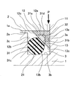
- FIG. 2 shows a sealing device according to a first embodiment of the present invention.
- the sealing device according to the comparative example shown in FIG. 1 (A) is configured as follows.
- this sealing device is mounted in an annular mounting groove 3 provided on the outer peripheral surface 1a of one member 1 of the two members 1 and 2 moving relative to each other (relative rotation or relative rocking) and The two members 1 and 2 are sealed by bringing them into close contact with the other member 2 located on the outer peripheral side and one side wall 3a of the mounting groove 3, and a resin seal made of PTFE or the like as its component It has a ring 11 and a rubber ring 21 as a spring means.
- the mounting groove 3 has a half-cut rectangular shape.
- the seal ring 11 has a cylindrical outer peripheral surface 11a, an axial end surface 11b in a plane perpendicular to the axis, and a tapered inner peripheral surface 11c, and is formed in a half-cut triangular shape. It is in close sliding contact with the inner circumferential surface 2a of the member 2 and is in close contact with one side wall 3a of the mounting groove 3 with one end face 11b in the axial direction.
- the rubber ring 21 is in the form of an O-ring having a half-cut circular cross section, and is interposed in a compressed state between the inner peripheral surface 11c of the seal ring 11 and the bottom wall 3b and the other side wall 3c of the mounting groove 3
- the seal ring 11 is pressed against the inner peripheral surface 2 a of the other member 2 and one side wall 3 a of the mounting groove 3 with a repulsive force.
- the seal ring 11 made of resin and having a half-cut triangular cross section in the comparative example is integrally provided with the radial direction portion 13 radially inward at one axial end of the cylindrical portion 12
- the support ring 31 made of a rigid material such as metal is assembled on the inner peripheral side of the cylindrical portion 12 in a half-cut cross-sectional L-shape or a substantially L-shape.
- the cylindrical portion 12 of the seal ring 11 is provided with a cylindrical outer peripheral surface 12a, an inner peripheral surface 12b similar to a cylindrical surface, and an axially opposite end surface 12c of a tapered surface. It is slidably in close contact with the inner circumferential surface 2a.
- the seal surface pressure at the close contact portion is appropriately set by the initial fitting margin of the cylindrical portion 12 with respect to the other member 2, or the support ring 31 is assembled on the inner peripheral side of the cylindrical portion 12
- the diameter of the portion 12 is appropriately set by enlargement.
- the other end face 12c in the axial direction may not be tapered, and may be, for example, a plane perpendicular to the axis.
- the radial direction portion 13 of the seal ring 11 includes an axial end surface 13a in the axial direction and an axial end surface 13b in the axial direction and an inner peripheral surface 13c in the axial direction.
- the end face 13 a is in close contact with one side wall 3 a of the mounting groove 3.
- the seal surface pressure at the close contact portion is appropriately set by the radial direction portion 13 being pressed in one axial direction by the rubber ring 21 through the support ring 31.
- the inner circumferential surface 13c may not be tapered, and may be, for example, cylindrical.
- the support ring 31 is provided with a cylindrical outer peripheral surface 31a, an axial end surface 31b in a plane perpendicular to the axis, and an inner peripheral surface 31c in a tapered surface, and one axial end and end surface 31b of the outer peripheral surface 31a. And a chamfered portion 31d in the form of a tapered surface parallel to the inner peripheral surface 31c between the outer peripheral end and the outer peripheral end portion to form a half-cut trapezoidal or substantially trapezoidal shape, and inside the cylindrical portion 12 of the seal ring 11 with the outer peripheral surface 31a.
- the end face 31 b of the seal ring 11 is in close contact with the other end face 13 b in the axial direction of the radial portion 13 of the seal ring 11.
- the outer peripheral surface 31a of the support ring 31 comprises "the site
- the rubber ring 21 is formed in an O-ring shape having a half-cut circular cross section, and is interposed in a compressed state between the inner peripheral surface 31 c of the support ring 31 and the bottom wall 3 b and the other side wall 3 c of the mounting groove 3
- the support ring 31 is pressed with a repulsive force, and the seal ring 11 is pressed via the support ring 31.
- the support ring 31 made of a rigid material such as metal is assembled on the inner peripheral side of the cylindrical portion 12 of the seal ring 11 made of resin, the support ring 31 has a cylindrical shape. The function of supporting the portion 12 from the inner peripheral side is exhibited. Therefore, even if pressure (sealing fluid pressure) P acts on seal ring 11 from the outer peripheral side, seal ring 11 is hardly deformed in the inner peripheral direction, and outer peripheral surface 11 a of seal ring 11 and the inner peripheral surface of the other member 2 Since it is hard to generate a radial direction gap between 2a and 2a, it is possible to suppress the leakage of the pressure P which makes this route a leak path.
- the support ring 31 has the repulsion force of the rubber ring 21.
- the support ring 31 has the repulsion force of the rubber ring 21.
- the support ring 31 bites into the corner where the inner peripheral surface 12b of the cylindrical portion 12 of the seal ring 11 and the other end surface 13b of the radial direction portion 13 intersect due to the wedge action.
- the chamfering portion 31d is provided on the shoulder portion of the support ring 31 as described above in the sealing device, so the support ring 31 does not contact the corner, thereby supporting the support ring 31 does not cut into the corner and damage the seal ring 11.
- the radial thickness dimension ((outer diameter-inner diameter) / 2) of the cylindrical portion 12 of the seal ring 11 is the radial distance between the bottom wall 3b of the mounting groove 3 and the inner peripheral surface 2a of the other member 2 Preferably, it is in the range of 20 to 30% of the dimension.
- the axial width of the seal ring 11 is preferably in the range of 90 to 100% of the axial width of the mounting groove 3.
- the radial interval between the outer peripheral surface 12a of the cylindrical portion 12 of the seal ring 11 and the inner peripheral end of the axial end face 13b of the radial direction portion 13 is the bottom wall 3b of the mounting groove 3 and the other It is preferable to set it in the range of 40 to 60% of the radial interval dimension between the inner peripheral surfaces 2a of the members 2.
- the axial width of the support ring 31 and the radial width of the support ring 31 ((outer diameter ⁇ inner diameter) / 2) are preferably equal to each other. Further, these dimensions are preferably in the range of 30 to 50% of the axial width dimension of the mounting groove 3.
- the radial width ((outside diameter-inner diameter) / 2) of the rubber ring 21 is 60 to 80 of the radial spacing between the bottom wall 3 b of the mounting groove 3 and the inner peripheral surface 2 a of the other member 2. It is preferable to make it the range of%.
- Each of the taper inclination angles with respect to the central axis is preferably 45 degrees. Also, these three planes may be arranged on the same plane by default.
- the material of the rubber ring 21 may be NBR, FKM, EPDM, or any other rubber-like elastic material.
- FIG. 3 shows a sealing device according to a comparative example
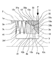
- FIG. 4 shows a sealing device according to a second embodiment of the present invention.
- the sealing device according to the comparative example shown in FIG. 3A is configured as follows.
- this sealing device is mounted in an annular mounting groove 3 provided on the outer peripheral surface 1a of one member 1 of the two members 1 and 2 moving relative to each other (relative rotation or relative rocking) and The two members 1 and 2 are sealed by bringing them into close contact with the other member 2 located on the outer peripheral side and one side wall 3a of the mounting groove 3, and a resin seal made of PTFE or the like as its component It has a ring 11, a support ring 31 made of a rigid material such as metal, and a metal spring 41 as spring means.
- the mounting groove 3 has a half-cut rectangular shape.
- the seal ring 11 has a cylindrical outer peripheral surface 11a, an axial end surface 11b in a plane perpendicular to the axis, and a tapered inner peripheral surface 11c, and is formed in a half-cut triangular shape. It is in close sliding contact with the inner circumferential surface 2a of the member 2 and is in close contact with one side wall 3a of the mounting groove 3 with one end face 11b in the axial direction.
- the support ring 31 has a tapered outer peripheral surface 31e, an axially perpendicular plane end face 31f, and a cylindrical inner peripheral surface 31g. It is slidably in close contact with the inner circumferential surface 11 c of 11.
- the metal spring 41 is coiled, and is interposed in a compressed state between the other axial end face 31 f of the support ring 31 and the other side wall 3 c of the mounting groove 3 and presses the support ring 31 with its repulsive force. At the same time, the seal ring 11 is pressed against the inner peripheral surface 2 a of the other member 2 and one side wall 3 a of the mounting groove 3 via the support ring 31.
- a plurality of metal springs 41 are equally spaced on the circumference of the sealing device.
- the seal ring 11 made of resin and having a half-cut triangular cross section in the comparative example is integrally provided with the radial direction portion 13 radially inward at one axial end of the cylindrical portion 12
- the projecting portion 33 provided on the outer peripheral surface 31 e of the support ring 31 is assembled on the inner peripheral side of the cylindrical portion 12.
- the cylindrical portion 12 of the seal ring 11 is provided with a cylindrical outer peripheral surface 12a, an inner peripheral surface 12b similar to a cylindrical surface, and an axially opposite end surface 12c of a tapered surface. It is slidably in close contact with the inner circumferential surface 2a.
- the seal surface pressure at the close contact portion is appropriately set by the initial fitting margin of the cylindrical portion 12 with respect to the other member 2, or the support ring 31 is assembled on the inner peripheral side of the cylindrical portion 12
- the diameter of the portion 12 is appropriately set by enlargement.
- the radial direction portion 13 of the seal ring 11 is provided with an axial end face 13a in the axial direction and an axial end face 13b in the axial direction, and an inner peripheral surface 13c in the tapered side.
- One end face 13 a is in close contact with one side wall 3 a of the mounting groove 3.
- the seal surface pressure at the close contact portion is appropriately set by the radial direction portion 13 being pressed in one axial direction by the metal spring 41 via the support ring 31.
- the support ring 31 has a tapered outer peripheral surface 31e, an axial end surface 31f having an axis-perpendicular planar shape, and an inner peripheral surface 31g having a cylindrical surface shape, and is formed into a semitriangular cross section.
- the projection 33 is provided.
- the projecting portion 33 has a cylindrical outer peripheral surface 33a and an axial end surface 33b perpendicular to the axis, and is supported between one axial end of the outer peripheral surface 33a and the outer peripheral end of the end surface 33b.
- a chamfered portion 33c in the form of a tapered surface parallel to the outer peripheral surface 31e of the ring 31 is formed into a half-cut trapezoidal or substantially trapezoidal shape, and is in close contact with the inner peripheral surface 12b of the cylindrical portion 12 of the seal ring 11 with the outer peripheral surface 33a.
- the one end face 33 b in the axial direction is in close contact with the other end face 13 b in the axial direction of the radial direction portion 13 of the seal ring 11.
- the outer peripheral surface 33a of the projection part 33 comprises "the site
- the metal spring 41 is coil-shaped, and is interposed in a compressed state between the other axial end face 31 f of the support ring 31 and the other side wall 3 c of the mounting groove 3 and presses the support ring 31 with its repulsive force.
- the seal ring 11 is pressed via the support ring 31.
- the projection 33 of the support ring 31 made of a rigid material such as metal is assembled on the inner peripheral side of the cylindrical portion 12 of the seal ring 11 made of resin, the projection of the support ring 31 A function 33 is exerted to support the cylindrical portion 12 of the seal ring 11 from the inner peripheral side. Therefore, even if pressure (sealing fluid pressure) P acts on seal ring 11 from the outer peripheral side, seal ring 11 is hardly deformed in the inner peripheral direction, and outer peripheral surface 11 a of seal ring 11 and the inner peripheral surface of the other member 2 Since it is hard to generate a radial direction gap between 2a and 2a, it is possible to suppress the leakage of the pressure P which makes this route a leak path.
- the support ring 31 has a repulsive force of the metal spring 41.
- the radial direction portion 13 of the seal ring 11 is pressed against one side wall 3a of the mounting groove 3 and the cylindrical portion 12 of the seal ring 11 is pressed against the inner peripheral surface 2a of the other member 2
- the wedge action is exhibited by the combination with the pressing force.
- the projection 33 of the support ring 31 is formed at the corner where the inner peripheral surface 12b of the cylindrical portion 12 of the seal ring 11 intersects with the other end face 13b of the radial direction 13 in the axial direction by the wedge action. Since there is a risk of biting in and damaging the seal ring 11, in the sealing device, the chamfered portion 33c is provided on the shoulder portion of the projection 33 of the support ring 31 as described above. There is no contact, so that the support ring 31 does not cut into the corner and damage the seal ring 11.
- the material of the seal ring 11 made of resin may be hard resin such as nylon other than PTFE.
Landscapes
- Engineering & Computer Science (AREA)
- General Engineering & Computer Science (AREA)
- Mechanical Engineering (AREA)
- Sealing Devices (AREA)
Abstract
Priority Applications (4)
| Application Number | Priority Date | Filing Date | Title |
|---|---|---|---|
| JP2014539673A JP5914682B2 (ja) | 2012-10-03 | 2013-09-25 | 密封装置 |
| US14/432,672 US20150260290A1 (en) | 2012-10-03 | 2013-09-25 | Sealing device |
| CN201380051699.8A CN104685269A (zh) | 2012-10-03 | 2013-09-25 | 密封装置 |
| EP13843166.3A EP2905517A4 (fr) | 2012-10-03 | 2013-09-25 | Dispositif d'étanchéité |
Applications Claiming Priority (2)
| Application Number | Priority Date | Filing Date | Title |
|---|---|---|---|
| JP2012220956 | 2012-10-03 | ||
| JP2012-220956 | 2012-10-03 |
Publications (1)
| Publication Number | Publication Date |
|---|---|
| WO2014054472A1 true WO2014054472A1 (fr) | 2014-04-10 |
Family
ID=50434800
Family Applications (1)
| Application Number | Title | Priority Date | Filing Date |
|---|---|---|---|
| PCT/JP2013/075794 WO2014054472A1 (fr) | 2012-10-03 | 2013-09-25 | Dispositif d'étanchéité |
Country Status (5)
| Country | Link |
|---|---|
| US (1) | US20150260290A1 (fr) |
| EP (1) | EP2905517A4 (fr) |
| JP (1) | JP5914682B2 (fr) |
| CN (1) | CN104685269A (fr) |
| WO (1) | WO2014054472A1 (fr) |
Cited By (2)
| Publication number | Priority date | Publication date | Assignee | Title |
|---|---|---|---|---|
| JP2018109421A (ja) * | 2016-12-28 | 2018-07-12 | Nok株式会社 | 密封装置 |
| US20210299903A1 (en) * | 2020-03-24 | 2021-09-30 | Hypertherm, Inc. | High-pressure seal for a liquid jet cutting system |
Families Citing this family (3)
| Publication number | Priority date | Publication date | Assignee | Title |
|---|---|---|---|---|
| CN105899858B (zh) * | 2014-05-29 | 2017-08-25 | Nok株式会社 | 密封结构及密封装置 |
| CN108019152A (zh) * | 2017-12-28 | 2018-05-11 | 苏州新锐合金工具股份有限公司 | 一种单金属密封轴承三牙轮钻头 |
| CN112901775B (zh) * | 2021-01-13 | 2022-12-30 | 西安近代化学研究所 | 一种由密封圈从内至外上下交替组合成型的片状径向密封装置 |
Citations (6)
| Publication number | Priority date | Publication date | Assignee | Title |
|---|---|---|---|---|
| JPS5728953U (fr) * | 1980-07-24 | 1982-02-16 | ||
| JPH08193603A (ja) | 1993-11-05 | 1996-07-30 | Fichtel & Sachs Ag | 揺動形アクチュエータ |
| JPH1178851A (ja) | 1997-09-10 | 1999-03-23 | Nabco Ltd | マスタシリンダにおけるシールリングの傾き防止方法 |
| JP2002156043A (ja) * | 2000-11-20 | 2002-05-31 | Nok Corp | 密封装置 |
| JP3403694B2 (ja) | 2000-05-17 | 2003-05-06 | ジャパン・ハムワージ株式会社 | ロータリーベーン式舵取機のリングシール構造 |
| JP2006329337A (ja) * | 2005-05-26 | 2006-12-07 | Nok Corp | 密封構造及び樹脂製シールリング |
Family Cites Families (21)
| Publication number | Priority date | Publication date | Assignee | Title |
|---|---|---|---|---|
| US3394939A (en) * | 1966-12-08 | 1968-07-30 | Johns Manville | Fluid pressure actuable seal |
| FR1588804A (fr) * | 1968-05-10 | 1970-03-16 | ||
| US3645543A (en) * | 1970-08-14 | 1972-02-29 | Parker Hannifin Corp | Shaft packing assembly |
| US3718338A (en) * | 1971-02-03 | 1973-02-27 | Shamban & Co W S | Sealing assembly |
| US4109716A (en) * | 1975-07-21 | 1978-08-29 | Otis Engineering Corporation | Seal |
| US4143586A (en) * | 1975-10-28 | 1979-03-13 | Poly-Seal | Mud pump piston |
| SE423436B (sv) * | 1978-10-31 | 1982-05-03 | Tetra Pak Int | Tetningsanordning for en roterbar axel |
| US4201392A (en) * | 1979-04-16 | 1980-05-06 | Grant Oil Tool Company | High and low pressure seal |
| US4489953A (en) * | 1981-12-10 | 1984-12-25 | Fmc Corporation | Fire-safe seal for swivel joint |
| GB2125492B (en) * | 1982-08-16 | 1986-07-02 | Ae Plc | Fluid seals for marine propulsion shafting |
| US5306021A (en) * | 1986-02-25 | 1994-04-26 | Morvant John D | V-shaped seal with anti-extrusion section |
| DK165803C (da) * | 1988-09-26 | 1993-06-21 | Shamban W S Europ | Taetningskonstruktion til taetning mellem to flader |
| US5111736A (en) * | 1989-04-04 | 1992-05-12 | Buchberger Anton H | Vented static seal assembly |
| US5511620A (en) * | 1992-01-29 | 1996-04-30 | Baugh; John L. | Straight Bore metal-to-metal wellbore seal apparatus and method of sealing in a wellbore |
| DE9315357U1 (de) * | 1993-10-11 | 1995-02-16 | Merkel Martin Gmbh Co Kg | Dichtungsanordnung |
| US5603511A (en) * | 1995-08-11 | 1997-02-18 | Greene, Tweed Of Delaware, Inc. | Expandable seal assembly with anti-extrusion backup |
| US6454272B1 (en) * | 1999-06-08 | 2002-09-24 | W. S. Shamban Europa A/S | Sealing arrangement and a sealing member therefor |
| US6502826B1 (en) * | 2000-10-30 | 2003-01-07 | Caterpillar Inc | Hydraulic cylinder piston seal |
| US8312805B1 (en) * | 2004-05-04 | 2012-11-20 | Novatech Holdings Corp. | High pressure pump piston |
| US7341258B2 (en) * | 2004-09-24 | 2008-03-11 | Greene, Tweed Of Delaware, Inc. | Cammed seal assembly with sealing ring having an angled leg portion and foot portion with elastomeric energizer element |
| DE102009022334B4 (de) * | 2009-05-13 | 2023-01-05 | Parker Hannifin Gmbh | Dichtung mit L-förmigem Querschnitt |
-
2013
- 2013-09-25 JP JP2014539673A patent/JP5914682B2/ja not_active Expired - Fee Related
- 2013-09-25 WO PCT/JP2013/075794 patent/WO2014054472A1/fr active Application Filing
- 2013-09-25 CN CN201380051699.8A patent/CN104685269A/zh active Pending
- 2013-09-25 US US14/432,672 patent/US20150260290A1/en not_active Abandoned
- 2013-09-25 EP EP13843166.3A patent/EP2905517A4/fr not_active Withdrawn
Patent Citations (6)
| Publication number | Priority date | Publication date | Assignee | Title |
|---|---|---|---|---|
| JPS5728953U (fr) * | 1980-07-24 | 1982-02-16 | ||
| JPH08193603A (ja) | 1993-11-05 | 1996-07-30 | Fichtel & Sachs Ag | 揺動形アクチュエータ |
| JPH1178851A (ja) | 1997-09-10 | 1999-03-23 | Nabco Ltd | マスタシリンダにおけるシールリングの傾き防止方法 |
| JP3403694B2 (ja) | 2000-05-17 | 2003-05-06 | ジャパン・ハムワージ株式会社 | ロータリーベーン式舵取機のリングシール構造 |
| JP2002156043A (ja) * | 2000-11-20 | 2002-05-31 | Nok Corp | 密封装置 |
| JP2006329337A (ja) * | 2005-05-26 | 2006-12-07 | Nok Corp | 密封構造及び樹脂製シールリング |
Non-Patent Citations (1)
| Title |
|---|
| See also references of EP2905517A4 * |
Cited By (2)
| Publication number | Priority date | Publication date | Assignee | Title |
|---|---|---|---|---|
| JP2018109421A (ja) * | 2016-12-28 | 2018-07-12 | Nok株式会社 | 密封装置 |
| US20210299903A1 (en) * | 2020-03-24 | 2021-09-30 | Hypertherm, Inc. | High-pressure seal for a liquid jet cutting system |
Also Published As
| Publication number | Publication date |
|---|---|
| EP2905517A1 (fr) | 2015-08-12 |
| EP2905517A4 (fr) | 2015-10-07 |
| CN104685269A (zh) | 2015-06-03 |
| JPWO2014054472A1 (ja) | 2016-08-25 |
| JP5914682B2 (ja) | 2016-05-11 |
| US20150260290A1 (en) | 2015-09-17 |
Similar Documents
| Publication | Publication Date | Title |
|---|---|---|
| US10612660B2 (en) | Gasket | |
| JP5547354B1 (ja) | 密封装置 | |
| WO2014054472A1 (fr) | Dispositif d'étanchéité | |
| WO2010098001A1 (fr) | Dispositif d'étanchéité | |
| US9316316B2 (en) | Segmented seal | |
| WO2018037918A1 (fr) | Dispositif d'étanchéité | |
| US10883606B2 (en) | Mechanical seal | |
| JP5758550B2 (ja) | メカニカルシール | |
| WO2018180307A1 (fr) | Structure d'agencement pour matériau d'étanchéité | |
| JP6577329B2 (ja) | メカニカルシール | |
| JP2012255495A (ja) | シールリング | |
| KR20150133636A (ko) | 축 시일 | |
| JP2015045357A (ja) | 密封装置 | |
| JP6895357B2 (ja) | 密封装置 | |
| JP6660759B2 (ja) | 密封装置 | |
| JP2015140861A (ja) | 密封装置 | |
| WO2018008520A1 (fr) | Structure d'agencement de matériau d'étanchéité | |
| JP2015025532A (ja) | 密封装置 | |
| JP2012154352A (ja) | 密封装置 | |
| JP2011007214A (ja) | 密封装置 | |
| JP2013227998A (ja) | 回転軸シール |
Legal Events
| Date | Code | Title | Description |
|---|---|---|---|
| 121 | Ep: the epo has been informed by wipo that ep was designated in this application |
Ref document number: 13843166 Country of ref document: EP Kind code of ref document: A1 |
|
| ENP | Entry into the national phase |
Ref document number: 2014539673 Country of ref document: JP Kind code of ref document: A |
|
| WWE | Wipo information: entry into national phase |
Ref document number: 14432672 Country of ref document: US |
|
| NENP | Non-entry into the national phase |
Ref country code: DE |
|
| WWE | Wipo information: entry into national phase |
Ref document number: 2013843166 Country of ref document: EP |