WO2014054315A1 - 安全キャビネット - Google Patents
安全キャビネット Download PDFInfo
- Publication number
- WO2014054315A1 WO2014054315A1 PCT/JP2013/066465 JP2013066465W WO2014054315A1 WO 2014054315 A1 WO2014054315 A1 WO 2014054315A1 JP 2013066465 W JP2013066465 W JP 2013066465W WO 2014054315 A1 WO2014054315 A1 WO 2014054315A1
- Authority
- WO
- WIPO (PCT)
- Prior art keywords
- safety cabinet
- work space
- air
- opening
- work
- Prior art date
- Legal status (The legal status is an assumption and is not a legal conclusion. Google has not performed a legal analysis and makes no representation as to the accuracy of the status listed.)
- Ceased
Links
Images


Classifications
-
- B—PERFORMING OPERATIONS; TRANSPORTING
- B01—PHYSICAL OR CHEMICAL PROCESSES OR APPARATUS IN GENERAL
- B01L—CHEMICAL OR PHYSICAL LABORATORY APPARATUS FOR GENERAL USE
- B01L1/00—Enclosures; Chambers
-
- B—PERFORMING OPERATIONS; TRANSPORTING
- B08—CLEANING
- B08B—CLEANING IN GENERAL; PREVENTION OF FOULING IN GENERAL
- B08B15/00—Preventing escape of dirt or fumes from the area where they are produced; Collecting or removing dirt or fumes from that area
- B08B15/02—Preventing escape of dirt or fumes from the area where they are produced; Collecting or removing dirt or fumes from that area using chambers or hoods covering the area
- B08B15/023—Fume cabinets or cupboards, e.g. for laboratories
Definitions
- the present invention relates to a safety cabinet, and more particularly, to a safety cabinet in which devices such as a centrifuge, an analyzer, and an observation device can be incorporated in the safety cabinet for infectious disease research and pharmaceutical development.
- the safety cabinet forms an air barrier by sucking air outside the safety cabinet from the work opening under the front and lower slide type front shutter formed on the front of the work space, forming an air barrier, and the atmosphere outside the safety cabinet work space and the safety cabinet Is physically shut off.
- the air sucked from the work opening passes through the inside of the safety cabinet, and removes infectious substances together with dust by an exhaust HEPA filter installed in the safety cabinet, and is exhausted out of the safety cabinet as clean air.
- the air blowing means for guiding air from the work opening to the exhaust HEPA filter may be provided inside the safety cabinet device or may be installed outside the safety cabinet device.
- the air outside the safety cabinet is directly taken into the work space of the safety cabinet, and there is no air supply HEPA filter at the top of the work space. Used when working with infectious substances in the work space, etc., for work that should ensure the safety of the worker and that do not require aseptic operation.
- the biohazard class I cabinet is configured so that infectious substances handled in the work space do not leak out of the safety cabinet by the air barrier at the work opening and the exhaust HEPA filter.
- Patent Document 1 Japanese Patent Laid-Open No. 2007-111596.
- the centrifugal separation tank of the centrifuge is arranged on the downstream side (lower surface) of the work space, and as described in the embodiment, the airflow entering from the vent hole under the shutter is below the centrifuge formed on the work table lower surface. It flows so as to surround the separation tank and is led to the return duct.
- This configuration clean air in the work space above the centrifuge is maintained, and the work space and the outside of the safety cabinet are isolated by an air barrier formed by a vent hole under the shutter.
- the airflow for the air barrier passes through the lower part of the centrifuge formed on the lower surface of the work space and is guided to the return duct.
- Patent Document 1 Japanese Patent Laid-Open No. 2007-111596.
- a lid is formed on the work table surface on the lower surface of the work space, and a separation tank of a centrifuge is formed below the cover.
- the airflow that has come down from the work space is sucked from three places: a vent hole in the work space, a space between the work table surface and the centrifuge separation tank, and a vent hole under the shutter and led to the return duct.
- the airflow sucked from the vent hole under the shutter passes through the return duct below the separation tank of the centrifuge and is guided to the blower.
- An object of the present invention is to provide a safety cabinet in which the inflow airflow is not affected by the position, size, and operation of the device incorporated in the work space, for example, the operation of opening and closing a lid such as a centrifuge. is there.
- the infectious spray (aerosol) generated in the work space does not stay in the work space, and is the shortest distance.
- the wind speed near the center of the opening becomes slow.
- a front shutter structure with a vertical slide type is used, and the work opening is set to about 200 mm during work or It is necessary to increase the wind speed of the entire opening, which increases the exhaust air volume of the exhaust fan and increases the heat load of the building.
- Another object of the present invention is to improve the wind speed distribution in the work opening, eliminate the need for a sliding front shutter, and secure an air barrier with the minimum necessary wind speed, thereby reducing power consumption and building thermal load. It is to suppress.
- Another object of the present invention is to provide an airflow configuration in which the basic performance of the safety cabinet is not affected even when the lid of an embedded device such as a centrifuge is opened.
- the present invention provides a work space where an operator works, a front shutter formed on the front surface of the work space, a work opening connected to the work space below the front shutter, A front cabinet above the work opening, comprising: a safety cabinet having a suction unit for sucking air from the work opening and exhausting the air in the work space to the outside of the safety cabinet by a blower through an air cleaning unit.
- a front shutter rectifying plate inclined inward of the work space is formed below the front shutter, and left and right side wall surfaces in the work space are provided, and the side wall surface and the side surface of the safety cabinet are provided.
- a side exhaust flow path is formed, first slits or punching holes are formed in the left and right side wall surfaces, and air in the working space is passed through the slits or punching holes to the side. Feeding the exhaust passage, and wherein the evacuating via said air cleaning unit.
- the first slit or the punching hole is formed below the front shutter rectifying plate in the extension line direction.
- a chamber is provided between the ceiling plate of the work space and the HEPA filter of the air cleaning means, the side exhaust flow path is connected to the chamber, and laterally extends to the back side of the ceiling plate.
- the second slit is formed in the above.
- the wind speed of the suction airflow (inflow airflow) formed in the work opening when a device such as an analyzer or an observation device is installed in a work space of a safety cabinet, and placed or fixed, the wind speed of the suction airflow (inflow airflow) formed in the work opening and It is possible to provide a safety cabinet in which the inflow airflow is not affected by the position of the airflow, the position of the apparatus, the operation of the device, for example, the operation of opening and closing a lid such as a centrifuge.
- infectious sprays generated in the work space are exhausted at the shortest distance without staying in the work space.
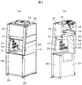
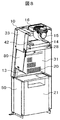
- the external appearance perspective view and longitudinal cross-sectional view of the safety cabinet carrying the class I type centrifuge which shows 1st Embodiment of this invention are shown.
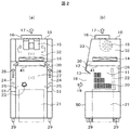
- the front sectional drawing and side sectional drawing of the safety cabinet of this invention shown in FIG. 1 are shown.
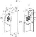
- the simple model for analysis for the voxel analysis of the safety cabinet of the present invention is shown.
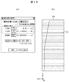
- the analysis conditions and analysis range for voxel analysis of the safety cabinet are shown.
- the analysis result of the flow of the air in the center sectional view shown to FIG. 3A is shown.
- the longitudinal cross-sectional view of the simple model for an analysis of the safety cabinet which has a front shutter rectifier of the present invention is shown.
- the analysis result of the flow of the air by the front shutter rectifier of FIG. 4A is shown.
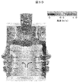
- FIG. 5A shows an analysis result of air flow in a central vertical portion of the safety cabinet of FIG. 5A.
- the analysis result of the air flow of the center horizontal part of the safety cabinet of FIG. 5A is shown.
- the analysis result of the air flow of the front part of the safety cabinet of FIG. 5A is shown.
- inner side of the ceiling board of the work space upper part of this invention is shown.
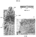
- the analysis result of the air flow of the safety cabinet of FIG. 6A is shown.
- the perspective view of the safety cabinet when mounting the centrifuge of this invention is shown.
- the cross-sectional perspective view of the safety cabinet which made the front shutter which shows 2nd Embodiment of this invention movable is shown.
- cover of the centrifuge which shows 3rd Embodiment of this invention, and varies the flow volume of a fan is shown.
- the side view of the safety cabinet for demonstrating the area and the wind speed in the opening part of the working space which shows 4th Embodiment of this invention, and the slit of the side wall surface on either side is shown.
- FIG. 1 shows an external perspective view and a longitudinal sectional view of a class I type safety cabinet equipped with a centrifuge showing Embodiment 1 of the present invention
- FIG. 2 shows a front sectional view of the safety cabinet of FIG. Side surface sectional drawing is shown.
- Class I type safety cabinets generally have a structure that prevents the discharge of aerosol by injecting air from the entire opening for the purpose of protecting workers, and directly injects indoor air and exhausts HEPA filters. It is the composition which discharges through.
- the safety cabinet of the present invention shown in FIGS. 1 and 2 is an improvement based on this class I configuration.
- 10 is a safety cabinet
- 11 is a work space where an operator works
- 12 is a fixed front shutter disposed above the opening of the work space
- 13 is a tip of the fixed front shutter 12.
- the left and right walls 31 have exhaust slits
- 21 is a centrifuge disposed below the work space
- 22 is a lid of the centrifuge 21
- 23 is an infectious substance.
- Reference numeral 24 denotes a side exhaust passage disposed on the left and right sides of the work space
- 25 denotes an air flow flowing from the work space to the side exhaust passage 24 through a slit 20 (referred to as a first slit)
- 26 denotes a flow in the side exhaust passage 24.
- 27 indicates a negative pressure in the work space
- 28 indicates a slit (referred to as a second slit) disposed on the back side of the ceiling plate 41 in the work space
- 29 indicates a caster
- 30 indicates the left and right sides of the work space.
- a chamber (referred to as a first chamber) in which air exhausted from the slit 20 on the wall surface and the slit 28 on the back side of the ceiling plate 41 gathers, 31 is the left and right side wall surfaces of the work space, 32 is the air after passing through the HEPA filter 14 A chamber for exhausting air from the blower 15 (referred to as a second chamber), 33 is an upper front part of the cabinet body, 50 is a lower front part of the cabinet body, and 51 is a side part of the cabinet body.
- a first chamber in which air exhausted from the slit 20 on the wall surface and the slit 28 on the back side of the ceiling plate 41 gathers
- 31 is the left and right side wall surfaces of the work space
- 32 is the air after passing through the HEPA filter 14
- a chamber for exhausting air from the blower 15 (referred to as a second chamber)
- 33 is an upper front part of the cabinet body
- 50 is a lower front part of the cabinet body
- 51 is a side part of the cabinet body.
- a fixed front shutter 12 is disposed above the opening 18 of the work space 11, and a front shutter rectifying plate 13 is inclined to the inside of the work space at the lower end of the fixed front shutter 12. Formed and arranged.
- this front shutter rectifying plate 13 is not formed and only the fixed front shutter 12 is provided, the air inflow air 19 into the work space is along the entire peripheral side wall of the lower surface of the fixed front shutter 12 and the opening 18 of the work space. Therefore, there is a possibility that a wind speed distribution can be achieved in which the wind speed increases and the wind speed near the center of the work space 18 decreases.
- a front shutter rectifying plate 13 is disposed. This effect will be described later.
- a ceiling plate 41 is formed on the upper side of the work space 11, and a space is formed on the upper portion of the ceiling plate 41 by a ceiling surface and a surface on which the HEPA filter 14 is disposed, and a chamber for collecting air exhausted from the work space 11 30 is formed.
- the air in the chamber 30 is sucked into the HEPA filter 14 and filters dust, infectious substances 23, and the like.
- the clean air that has passed through the HEPA filter 14 is exhausted to the outside of the safety cabinet 10 by the blower 15 via the exhaust duct 16.
- a chamber 32 of clean air space in which the blower 15 is installed is formed.
- a space is formed by the left and right side wall surfaces 31 of the work space 11 and the side surface portion 51 of the safety cabinet 10, and the air in the work space 11 is caused to flow into this space to form the side exhaust flow path 24.
- Upper portions of the side exhaust passages 24 formed on the left and right sides of the work space are connected to the first chamber 30.
- the air in the work space 11 flows through the slits formed in the left and right wall surfaces of the work space and flows into the side exhaust flow path 24.
- the vertically elongated slit holes are formed in the vertical direction on the left and right side wall surfaces of the work space, but they may be punched holes or elliptical holes.
- a plurality of second slits 28 that are elongated in the width direction are arranged at the back of the ceiling plate 41 so that the air on the back side in the work space flows upward.
- the front shutter rectifying plate 13 disposed below the fixed front shutter 12 is provided to improve the wind speed distribution of the working opening 18 and has a length of 50 to 150 mm and a fixed angle of fixed. From the front shutter 12 toward the work space 11, it is fixed at an angle of 30 to 60 ° from the horizontal.
- the material may be a transparent glass surrounded by a SUS frame or a steel plate.
- left and right side slits 20 for exhaust provided in the work space 11 are directed from the front to the back of the work space 11 in order to rectify the inflow air flowing from outside the cabinet. Thus, the opening area is gradually reduced.
- a centrifuge 21 is mounted in the lower part of the work space of the safety cabinet 10. As shown in FIG. 7, the centrifuge 21 is mounted by removing the lower front plate 50 of the safety cabinet 10 and moving the centrifuge 21 with the casters 50 to the lower part of the work space. Moreover, when the lid 22 of the centrifuge is opened so that the operator can work easily, the centrifuge is installed so as to fall down on the back side of the work space. After installation, the lower front plate 50 of the safety cabinet is attached. Further, the lower front plate 50 of the cabinet 10 may be fixed by screwing on both sides or may be provided with a hinge on one side and fixed as a door. Casters 29 are provided on the legs of the safety cabinet so that they can be moved with a light force when moving.
- FIG. 3A to FIG. 3C the front shutter rectifying plate 13 is not formed, the slits 20 formed on the left and right wall surfaces 31 of the work space are arranged in three rows in the vertical direction, and the shape is an elongated vertically long hole, and the slit is arranged.
- This area is set at the approximate center of the wall, and the air flow is analyzed when the entire area is formed in a rectangular area.
- FIG. 3A shows a perspective view and a longitudinal sectional view of a simple model for analysis of a safety cabinet to be analyzed.
- the width (L2) of the cabinet is 850 mm
- the height (L1) is 1950 mm
- the depth (L3) is 780 mm
- the width (L6) of the opening in the work space is 650 mm
- the height (L5) of the opening of the space is 550 mm.
- the average wind speed is 0.5 m / s.
- the slit 20 has a configuration in which 60 holes of 100 mm ⁇ 10 mm are formed on one side.
- FIG. 3B shows the conditions to be analyzed
- FIG. 3B (a) shows the input unit representing the setting of the cross-sectional calculation
- FIG. 3B (b) shows the range to be analyzed.
- the height direction of the simplified model for analysis of the safety cabinet is the y direction
- the width direction is the x direction
- the depth direction is the z direction
- the number of cross sections is 300 in the y direction
- the z direction is 175
- the voxel size display is about 9.2 million cells
- the analysis range is a range including the entire cabinet as shown in FIG. 3B (b).
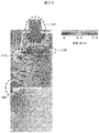
- FIG. 3C shows the air flow in the longitudinal section of the safety cabinet shown in FIG. 3A (b).
- 100 indicates the air flow below the opening of the work space
- 120 indicates the air flow in the chamber 30 above the ceiling plate 41
- 130 indicates the air flow in the exhaust chamber 32.
- the region from 100 to 130 is a portion where the wind speed is high, and in the figure, the wind speed is indicated by an arrow line, and the black bundle portion indicates that the wind speed is high.
- the air flow is about 1 m / s with respect to the average wind speed of 0.5 m / s.
- the air that has flowed in as shown by the arrows flows in from the opening and flows toward the back, and since there is no front shutter rectifying plate, it is caught at the upper end of the opening of the work space. Turbulent flow is generated, and the air is exhausted from the slits 20 on the left and right side wall surfaces.
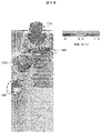
- FIG. 4A shows a configuration in which a front shutter rectifying plate 13 is inclined at the front end of the fixed front shutter 12 and inclined toward the work space.
- the slits 20 formed on the left and right side walls in the work space are the same as in FIG. 3A, and 60 holes of 100 mm ⁇ 10 mm (both sides) are formed.
- the air flow in the configuration of FIG. 4A is shown in FIG. 4B.
- the part where the wind speed is high is a part surrounded by a circle (dotted line)
- 140 indicates the air flow below the opening of the work space
- 150 indicates the air flow above the opening of the work space.
- Reference numeral 160 denotes an air flow in the chamber 30 above the ceiling plate
- 170 denotes an air flow in the exhaust chamber 32.
- the air that flows in along the front shutter rectifying plate 13 out of the air that flows in from the opening is caught in the upper side of the work space and generates turbulent flow. That is, when the arrangement of the slits 20 on the left and right side walls is the same, and the front shutter rectifying plate 13 is arranged, the formation of the slits 20 is the same as the configuration of FIG. To do.
- the front shutter rectifying plate 13 is arranged, the slit 20 is arranged, and the flow of air when the arrangement of the slit 20 is changed is analyzed.
- the front shutter rectifying plate 13 is disposed at the front end of the fixed front shutter 12 so as to be inclined toward the working space, and the arrangement of the slits 20 formed on the left and right side wall surfaces of the working space is an extension of the front shutter rectifying plate 13.
- positioned below the direction is shown, and the flow of the air of this structure is analyzed.
- FIG. 5A shows a cross-sectional perspective view of a simplified analysis model of a safety cabinet in which the front shutter rectifying plate 13 is formed in the upper part of the opening and the slit 20 is disposed below the extending direction 40 of the front shutter rectifying plate 13.
- B shows a side view.
- the slits 20 are arranged in three rows below the extension line 40 of the front shutter rectifying plate 13, and the range of the arrangement is substantially triangular.
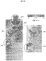
- FIG. 5B shows the analysis result of the air flow having the configuration shown in FIG. 5A (a).
- the part where the wind speed is high is a portion surrounded by a circle (dotted line)
- 180 indicates the air flow below the opening of the work space
- 190 indicates the air flow above the opening of the work space
- 200 indicates the air flow in the chamber 30 above the ceiling plate 41
- 210 indicates the air flow in the exhaust chamber 32.
- the slit 20 It concentrates in the slit 20 arrange
- the front shutter rectifying plate 13 is disposed on the upper side of the opening so as to be inclined inward of the work space, and the range of the slit 20 disposed on the left and right side walls of the work space is below the extension line direction of the rectifying plate 13.
- FIG. 5C shows the analysis result of the horizontal air flow in the central portion of the work space in the simplified analysis model of the safety cabinet shown in FIG. 5A.
- a large amount of air with high wind speed passes through the slit 20 from the work space and flows in the side exhaust passage 24, and the wind speed at the center is low and the wind speed on both sides is high in the work space.
- the wind speed is low on the back side of the work space, and there is a possibility that it may be hazy.
- FIG. 5D shows the analysis result of the air flow in the front central section of the working space and the exhaust part in the simplified model for analysis of the safety cabinet shown in FIG. 5A.
- the air flow in the vicinity of the center from the opening of the work space has a low wind speed at the center of the work space, the wind speed increases as it approaches the left and right side walls, and the portion where the slit 20 is located is higher. That is, although the slits 20 are arranged in three rows in the vertical direction, it can be seen that the wind speed at that portion is high. Further, in the side exhaust passage 24 and the chamber 30 on the ceiling plate, the wind speed is high, and the wind speed of the exhaust duct portion of the exhaust chamber 32 is high. Also, the wind speed at the upper center of the work space is low.
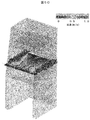
- FIG. 6A shows a longitudinal sectional perspective view and a plan view of the ceiling board 41 of a simple model for analysis of a safety cabinet in which slits 28 are arranged.
- the front shutter rectifying plate 13 is arranged above the opening of the work space
- the slit 20 is arranged below the extending line direction of the rectifying plate 13, and below the extending line direction of the rectifying plate 13.
- a plurality of slits 20 are vertically arranged on the side, the entire range of the slits is substantially triangular, and the slits 28 are arranged in the width direction on the back side of the ceiling surface 41. Further, in this configuration, the circle A is a place where air easily stagnates.
- FIG. 6B shows the analysis result of the air flow in the configuration of FIG. 6A.
- the air that has flowed in through the opening of the work space travels straight and flows through the slits 20 on the left and right side wall surfaces 31, and the air that flows in along the rectifying plate 13 flows on the slits on the left and right side wall surfaces.
- the air that flows in along the rectifying plate 13 flows on the slits on the left and right side wall surfaces.
- the stagnation is eliminated by the slit 28 arranged on the back side of the ceiling board.
- Example 2 Next, it forms so that the front shutter 80 which has arrange
- a configuration that can be adjusted is shown in FIG.
- the front shutter 80 is formed so as to be sandwiched between the upper front portion 33 and the upper front portion back plate 42 of the safety cabinet and is configured to be slidable. Further, when the worker works, the front shutter rectifying plate 13 can be made detachable so that it can be removed if it hinders the work.
- the front shutter 80 is transparent so that the work space can be seen. In the case of Example 1, since it is a fixed type, it may be opaque.
- a handle is formed in the center of the outer side of the front shutter 80 so that the operator can perform an up / down sliding operation.
- 21 is a centrifuge
- 22 is a centrifuge lid
- 60 is a sensor for detecting the opening / closing of the centrifuge lid
- 61 is a lid opening / closing sensor input circuit
- 62 is a detection for detecting the opening / closing of the lid.
- a circuit, 63 is a controller for controlling the motor
- 64 is a motor for driving the blower 15, and 15 is a blower.
- the operator puts the sample between the centrifuges, inserts the centrifuge between the rotors, opens the lid of the centrifuge, puts the rotor in the chamber of the separator, closes the lid, and turns on the SW of the centrifuge To do.
- open the centrifuge lid remove the rotor and close the lid.
- An open / close sensor 60 arranged at the lid is installed, and when the lid of the centrifuge is opened, a lid open signal is sent to the lid open / close sensor input circuit 61, and the detection circuit 62 detects that the lid has been opened.
- the motor controller 63 temporarily increases the rotating power for a predetermined time, increases the rotational speed of the motor 64, and increases the wind force of the blower 15.
- the centrifuge 21 and the safety cabinet 10 are not integrated, they are connected via a connector or wirelessly transmitted to the cabinet body to connect the sensor output.
- a sensor for detecting the opening / closing of the centrifuge lid an optical sensor is used to emit light on a part of the lid surface, receive reflection from the lid surface, and detect the opening / closing of the lid.
- switches that turn on and off at the same time, and mechanical switches such as ⁇ switches.
- Example 4 Next, the optimal area ratio and wind speed of the slit 20 of the opening surface of the safety cabinet of Example 4 of this invention and the side wall surface of the right and left of a working space are demonstrated.
- the optimum opening area of the entire slit 20 disposed on the left and right side walls of the work space is obtained.
- the resistance due to the speed change when exhausting from the work space and passing through the slit 20 in the in-machine resistance of the safety cabinet is set to 2 to 3 Pa depending on the characteristics of the blower 15. Determine to be.
- the in-machine resistance is a pressure loss where a speed change occurs in the flow path
- the pressure loss ⁇ P due to the speed change is expressed by the following equation.
- Equation 1 ⁇ ⁇ (1/2) ⁇ ⁇ ⁇ (V1 2 ⁇ V2 2 ) (Equation 1)
- ⁇ is the pressure loss coefficient
- ⁇ is the density of the fluid (1.2 for air)
- V1 is the speed before the speed changes
- V2 is the speed after the speed changes.
- the pressure loss coefficient ⁇ varies depending on the material in the flow path, the fluid velocity, etc., it may not be 1 or more in the case of a large size, so 1 may be used in the rough calculation.
- the total area S OUT of the slits 20 is 100 mm ⁇ 10 mm in the area of one slit, and 40 are arranged on one side.
- the air volume Q in the work space is usually 0.5 m / s because the velocity of the air flowing into the opening is 0.5 m / s.
- Q is 10.7 m 3 / s.
- the ratio of the wind speed of the slits on the left and right side wall surfaces in the work space to the wind speed of the air flowing into the opening is 4.4. Therefore, the ratio of the wind speed of the slits on the left and right side wall surfaces in the work space to the wind speed of the air flowing into the opening may be about four times as high.
- the wind speed distribution of the work opening 18 is improved, and an air barrier can be secured even in the case of a wide opening where the height of the work opening 18 exceeds 400 mm, thereby improving workability.
- the infectious substance 23 generated during the experiment work in a device such as a centrifuge, an analyzer, or an observer incorporated in the safety cabinet 10 is efficiently transferred from the work space 11 to the side exhaust passages 24 installed on the left and right of the work space. Discharged. Since the configuration does not exhaust from the back of the work space 11, even when a large device is mounted in the safety cabinet 10, the depth space can be minimized, the carry-in route and the installation space can be secured, and the centrifugal built into the safety cabinet 10. Even when the open / close lid 22 of the apparatus 21 such as a separator, analyzer or observer moves up and down, a stable air flow can be formed without obstructing the exhaust path so that the work can be performed with peace of mind. became.
- first chamber Between the ceiling plate and the HEPA filter Chamber (first chamber), 31... Left and right side wall surfaces of work space, 32 .. Exhaust chamber (second chamber), 40. Extension line of front shutter rectifier plate, 41. Ceiling plate of work space, Side portions of 1 .. safety cabinet, 60 .. cover opening and closing sensor of the centrifuge, 62 .. cover opening and closing sensor sensing circuit, 63 .. motor controller, for 64 .. blower motor, 80 .. movable front shutter.
Landscapes
- Health & Medical Sciences (AREA)
- Clinical Laboratory Science (AREA)
- Chemical & Material Sciences (AREA)
- Chemical Kinetics & Catalysis (AREA)
- Devices For Use In Laboratory Experiments (AREA)
- Ventilation (AREA)
- Centrifugal Separators (AREA)
Priority Applications (2)
| Application Number | Priority Date | Filing Date | Title |
|---|---|---|---|
| IN11130DEN2014 IN2014DN11130A (enExample) | 2012-10-04 | 2013-06-14 | |
| SG11201500074XA SG11201500074XA (en) | 2012-10-04 | 2013-06-14 | Safety cabinet |
Applications Claiming Priority (2)
| Application Number | Priority Date | Filing Date | Title |
|---|---|---|---|
| JP2012222133A JP5873413B2 (ja) | 2012-10-04 | 2012-10-04 | 安全キャビネット |
| JP2012-222133 | 2012-10-04 |
Publications (1)
| Publication Number | Publication Date |
|---|---|
| WO2014054315A1 true WO2014054315A1 (ja) | 2014-04-10 |
Family
ID=50434651
Family Applications (1)
| Application Number | Title | Priority Date | Filing Date |
|---|---|---|---|
| PCT/JP2013/066465 Ceased WO2014054315A1 (ja) | 2012-10-04 | 2013-06-14 | 安全キャビネット |
Country Status (5)
| Country | Link |
|---|---|
| JP (1) | JP5873413B2 (enExample) |
| IN (1) | IN2014DN11130A (enExample) |
| MY (1) | MY174864A (enExample) |
| SG (1) | SG11201500074XA (enExample) |
| WO (1) | WO2014054315A1 (enExample) |
Cited By (4)
| Publication number | Priority date | Publication date | Assignee | Title |
|---|---|---|---|---|
| CN108405544A (zh) * | 2018-05-10 | 2018-08-17 | 北京天辰昊桦科技有限公司 | 一种净化操作区污染物的装置 |
| CN111715416A (zh) * | 2020-06-29 | 2020-09-29 | 徐州医科大学 | 一种气溶胶颗粒吸附净化离心机 |
| SE2050211A1 (sv) * | 2020-02-25 | 2021-08-26 | KYOCERA Fineceramics Solutions GmbH | Abluftreiniger |
| TWI801898B (zh) * | 2020-09-28 | 2023-05-11 | 日商日立產機系統股份有限公司 | 安全櫃體 |
Families Citing this family (7)
| Publication number | Priority date | Publication date | Assignee | Title |
|---|---|---|---|---|
| SE539939C2 (sv) * | 2014-10-23 | 2018-01-30 | Qleanair Scandinavia Ab | Dragrum med perforerad vägg |
| JP6787657B2 (ja) * | 2015-10-15 | 2020-11-18 | 株式会社ゲンダイプラント | 揮発性薬剤注液装置 |
| US10874012B2 (en) | 2016-10-19 | 2020-12-22 | Hitachi Industrial Equipment Systems Co., Ltd. | Biosafety cabinet and clean air device |
| JP7093741B2 (ja) * | 2019-03-27 | 2022-06-30 | 株式会社日立産機システム | 気流の可視化方法、及び、それを用いたシミュレーション装置 |
| JP7281432B2 (ja) * | 2020-06-10 | 2023-05-25 | 株式会社日立産機システム | パスボックス |
| KR20230090361A (ko) | 2021-06-15 | 2023-06-21 | 가부시키가이샤 히다치 산키시스템 | 안전 캐비닛 |
| KR102826934B1 (ko) * | 2023-09-05 | 2025-06-30 | 삼성전자주식회사 | 설비 전방 단부 모듈 및 이를 포함하는 기판 처리 설비 |
Citations (7)
| Publication number | Priority date | Publication date | Assignee | Title |
|---|---|---|---|---|
| JPS52170393U (enExample) * | 1976-06-17 | 1977-12-24 | ||
| JPH09170794A (ja) * | 1995-12-19 | 1997-06-30 | Itoki Crebio Corp | ドラフトチャンバーの排気制御装置 |
| JP2005502856A (ja) * | 2001-09-18 | 2005-01-27 | バルドナー ラボラインリヒトゥンゲン ゲーエムベーハー ウント ツェーオー.カーゲー | 排気装置 |
| JP2005334771A (ja) * | 2004-05-27 | 2005-12-08 | Hitachi Industrial Equipment Systems Co Ltd | 清浄作業台 |
| JP2007111596A (ja) * | 2005-10-19 | 2007-05-10 | Airtech Japan Ltd | 遠心分離機を組み込んだ安全キャビネット及びバイオクリーンベンチ |
| JP2009095771A (ja) * | 2007-10-17 | 2009-05-07 | Oriental Giken Kogyo Kk | ヒュームフード |
| JP2010094603A (ja) * | 2008-10-16 | 2010-04-30 | Dalton Corp | ドラフトチャンバー |
Family Cites Families (1)
| Publication number | Priority date | Publication date | Assignee | Title |
|---|---|---|---|---|
| US9056339B2 (en) * | 2010-08-27 | 2015-06-16 | Exposure Control Technologies, Inc. | Airfoil and baffle assemblies that reduce airflow requirements for fume hoods and fume hoods incorporating same |
-
2012
- 2012-10-04 JP JP2012222133A patent/JP5873413B2/ja active Active
-
2013
- 2013-06-14 SG SG11201500074XA patent/SG11201500074XA/en unknown
- 2013-06-14 WO PCT/JP2013/066465 patent/WO2014054315A1/ja not_active Ceased
- 2013-06-14 MY MYPI2015000105A patent/MY174864A/en unknown
- 2013-06-14 IN IN11130DEN2014 patent/IN2014DN11130A/en unknown
Patent Citations (7)
| Publication number | Priority date | Publication date | Assignee | Title |
|---|---|---|---|---|
| JPS52170393U (enExample) * | 1976-06-17 | 1977-12-24 | ||
| JPH09170794A (ja) * | 1995-12-19 | 1997-06-30 | Itoki Crebio Corp | ドラフトチャンバーの排気制御装置 |
| JP2005502856A (ja) * | 2001-09-18 | 2005-01-27 | バルドナー ラボラインリヒトゥンゲン ゲーエムベーハー ウント ツェーオー.カーゲー | 排気装置 |
| JP2005334771A (ja) * | 2004-05-27 | 2005-12-08 | Hitachi Industrial Equipment Systems Co Ltd | 清浄作業台 |
| JP2007111596A (ja) * | 2005-10-19 | 2007-05-10 | Airtech Japan Ltd | 遠心分離機を組み込んだ安全キャビネット及びバイオクリーンベンチ |
| JP2009095771A (ja) * | 2007-10-17 | 2009-05-07 | Oriental Giken Kogyo Kk | ヒュームフード |
| JP2010094603A (ja) * | 2008-10-16 | 2010-04-30 | Dalton Corp | ドラフトチャンバー |
Cited By (5)
| Publication number | Priority date | Publication date | Assignee | Title |
|---|---|---|---|---|
| CN108405544A (zh) * | 2018-05-10 | 2018-08-17 | 北京天辰昊桦科技有限公司 | 一种净化操作区污染物的装置 |
| SE2050211A1 (sv) * | 2020-02-25 | 2021-08-26 | KYOCERA Fineceramics Solutions GmbH | Abluftreiniger |
| SE544303C2 (sv) * | 2020-02-25 | 2022-03-29 | KYOCERA Fineceramics Solutions GmbH | Frånluftrenare för laboratoriedragskåp eller laboratorieskåp |
| CN111715416A (zh) * | 2020-06-29 | 2020-09-29 | 徐州医科大学 | 一种气溶胶颗粒吸附净化离心机 |
| TWI801898B (zh) * | 2020-09-28 | 2023-05-11 | 日商日立產機系統股份有限公司 | 安全櫃體 |
Also Published As
| Publication number | Publication date |
|---|---|
| MY174864A (en) | 2020-05-19 |
| JP5873413B2 (ja) | 2016-03-01 |
| IN2014DN11130A (enExample) | 2015-09-25 |
| JP2014073457A (ja) | 2014-04-24 |
| SG11201500074XA (en) | 2015-03-30 |
Similar Documents
| Publication | Publication Date | Title |
|---|---|---|
| JP5873413B2 (ja) | 安全キャビネット | |
| TWI408317B (zh) | 具有抗擾動氣流能力的排油煙機 | |
| US7503842B2 (en) | Air curtain-assisted exhaust method and device thereof | |
| JP5073840B2 (ja) | 吸引捕集装置 | |
| JP6266127B2 (ja) | クリーンエア装置および塵埃点検方法 | |
| CN105744710A (zh) | 除尘除静电设备 | |
| JP5860334B2 (ja) | 動物飼育用安全キャビネット | |
| EP1657494B1 (en) | Exhaust hood | |
| KR102165033B1 (ko) | 계량 시스템 | |
| CN210385898U (zh) | 一种流量控制生物安全柜 | |
| JP2001033072A (ja) | 換気システム | |
| RU2605896C2 (ru) | Устройство выдувания очищенного воздуха | |
| JP7401915B2 (ja) | 局所空気清浄化装置 | |
| JP2015014381A (ja) | エアシャワー装置 | |
| CN211706804U (zh) | 一种新型生物安全柜 | |
| KR20220043005A (ko) | 안전 캐비닛 | |
| CN100473914C (zh) | 气帘辅助排气方法及其装置 | |
| CN213348918U (zh) | 一种带可检测前窗气流装置的生物安全柜 | |
| CN218981598U (zh) | 生物安全柜 | |
| JP6387529B2 (ja) | 手乾燥装置 | |
| JP2013085994A (ja) | 安全キャビネット | |
| JP5280216B2 (ja) | 全排気型安全キャビネット | |
| CN117123282B (zh) | 一种生物安全柜 | |
| KR102007899B1 (ko) | 실험실 흄후드 | |
| JP2013056308A (ja) | ドラフト装置 |
Legal Events
| Date | Code | Title | Description |
|---|---|---|---|
| 121 | Ep: the epo has been informed by wipo that ep was designated in this application |
Ref document number: 13843464 Country of ref document: EP Kind code of ref document: A1 |
|
| NENP | Non-entry into the national phase |
Ref country code: DE |
|
| 122 | Ep: pct application non-entry in european phase |
Ref document number: 13843464 Country of ref document: EP Kind code of ref document: A1 |