WO2014054315A1 - Safety cabinet - Google Patents
Safety cabinet Download PDFInfo
- Publication number
- WO2014054315A1 WO2014054315A1 PCT/JP2013/066465 JP2013066465W WO2014054315A1 WO 2014054315 A1 WO2014054315 A1 WO 2014054315A1 JP 2013066465 W JP2013066465 W JP 2013066465W WO 2014054315 A1 WO2014054315 A1 WO 2014054315A1
- Authority
- WO
- WIPO (PCT)
- Prior art keywords
- safety cabinet
- work space
- air
- opening
- work
- Prior art date
Links
Images


Classifications
-
- B—PERFORMING OPERATIONS; TRANSPORTING
- B01—PHYSICAL OR CHEMICAL PROCESSES OR APPARATUS IN GENERAL
- B01L—CHEMICAL OR PHYSICAL LABORATORY APPARATUS FOR GENERAL USE
- B01L1/00—Enclosures; Chambers
-
- B—PERFORMING OPERATIONS; TRANSPORTING
- B08—CLEANING
- B08B—CLEANING IN GENERAL; PREVENTION OF FOULING IN GENERAL
- B08B15/00—Preventing escape of dirt or fumes from the area where they are produced; Collecting or removing dirt or fumes from that area
- B08B15/02—Preventing escape of dirt or fumes from the area where they are produced; Collecting or removing dirt or fumes from that area using chambers or hoods covering the area
- B08B15/023—Fume cabinets or cupboards, e.g. for laboratories
Definitions
- the present invention relates to a safety cabinet, and more particularly, to a safety cabinet in which devices such as a centrifuge, an analyzer, and an observation device can be incorporated in the safety cabinet for infectious disease research and pharmaceutical development.
- the safety cabinet forms an air barrier by sucking air outside the safety cabinet from the work opening under the front and lower slide type front shutter formed on the front of the work space, forming an air barrier, and the atmosphere outside the safety cabinet work space and the safety cabinet Is physically shut off.
- the air sucked from the work opening passes through the inside of the safety cabinet, and removes infectious substances together with dust by an exhaust HEPA filter installed in the safety cabinet, and is exhausted out of the safety cabinet as clean air.
- the air blowing means for guiding air from the work opening to the exhaust HEPA filter may be provided inside the safety cabinet device or may be installed outside the safety cabinet device.
- the air outside the safety cabinet is directly taken into the work space of the safety cabinet, and there is no air supply HEPA filter at the top of the work space. Used when working with infectious substances in the work space, etc., for work that should ensure the safety of the worker and that do not require aseptic operation.
- the biohazard class I cabinet is configured so that infectious substances handled in the work space do not leak out of the safety cabinet by the air barrier at the work opening and the exhaust HEPA filter.
- Patent Document 1 Japanese Patent Laid-Open No. 2007-111596.
- the centrifugal separation tank of the centrifuge is arranged on the downstream side (lower surface) of the work space, and as described in the embodiment, the airflow entering from the vent hole under the shutter is below the centrifuge formed on the work table lower surface. It flows so as to surround the separation tank and is led to the return duct.
- This configuration clean air in the work space above the centrifuge is maintained, and the work space and the outside of the safety cabinet are isolated by an air barrier formed by a vent hole under the shutter.
- the airflow for the air barrier passes through the lower part of the centrifuge formed on the lower surface of the work space and is guided to the return duct.
- Patent Document 1 Japanese Patent Laid-Open No. 2007-111596.
- a lid is formed on the work table surface on the lower surface of the work space, and a separation tank of a centrifuge is formed below the cover.
- the airflow that has come down from the work space is sucked from three places: a vent hole in the work space, a space between the work table surface and the centrifuge separation tank, and a vent hole under the shutter and led to the return duct.
- the airflow sucked from the vent hole under the shutter passes through the return duct below the separation tank of the centrifuge and is guided to the blower.
- An object of the present invention is to provide a safety cabinet in which the inflow airflow is not affected by the position, size, and operation of the device incorporated in the work space, for example, the operation of opening and closing a lid such as a centrifuge. is there.
- the infectious spray (aerosol) generated in the work space does not stay in the work space, and is the shortest distance.
- the wind speed near the center of the opening becomes slow.
- a front shutter structure with a vertical slide type is used, and the work opening is set to about 200 mm during work or It is necessary to increase the wind speed of the entire opening, which increases the exhaust air volume of the exhaust fan and increases the heat load of the building.
- Another object of the present invention is to improve the wind speed distribution in the work opening, eliminate the need for a sliding front shutter, and secure an air barrier with the minimum necessary wind speed, thereby reducing power consumption and building thermal load. It is to suppress.
- Another object of the present invention is to provide an airflow configuration in which the basic performance of the safety cabinet is not affected even when the lid of an embedded device such as a centrifuge is opened.
- the present invention provides a work space where an operator works, a front shutter formed on the front surface of the work space, a work opening connected to the work space below the front shutter, A front cabinet above the work opening, comprising: a safety cabinet having a suction unit for sucking air from the work opening and exhausting the air in the work space to the outside of the safety cabinet by a blower through an air cleaning unit.
- a front shutter rectifying plate inclined inward of the work space is formed below the front shutter, and left and right side wall surfaces in the work space are provided, and the side wall surface and the side surface of the safety cabinet are provided.
- a side exhaust flow path is formed, first slits or punching holes are formed in the left and right side wall surfaces, and air in the working space is passed through the slits or punching holes to the side. Feeding the exhaust passage, and wherein the evacuating via said air cleaning unit.
- the first slit or the punching hole is formed below the front shutter rectifying plate in the extension line direction.
- a chamber is provided between the ceiling plate of the work space and the HEPA filter of the air cleaning means, the side exhaust flow path is connected to the chamber, and laterally extends to the back side of the ceiling plate.
- the second slit is formed in the above.
- the wind speed of the suction airflow (inflow airflow) formed in the work opening when a device such as an analyzer or an observation device is installed in a work space of a safety cabinet, and placed or fixed, the wind speed of the suction airflow (inflow airflow) formed in the work opening and It is possible to provide a safety cabinet in which the inflow airflow is not affected by the position of the airflow, the position of the apparatus, the operation of the device, for example, the operation of opening and closing a lid such as a centrifuge.
- infectious sprays generated in the work space are exhausted at the shortest distance without staying in the work space.
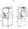
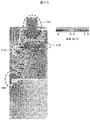
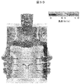
- the external appearance perspective view and longitudinal cross-sectional view of the safety cabinet carrying the class I type centrifuge which shows 1st Embodiment of this invention are shown.
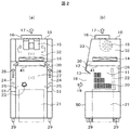
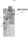
- the front sectional drawing and side sectional drawing of the safety cabinet of this invention shown in FIG. 1 are shown.
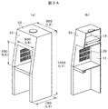
- the simple model for analysis for the voxel analysis of the safety cabinet of the present invention is shown.
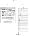
- the analysis conditions and analysis range for voxel analysis of the safety cabinet are shown.
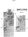
- the analysis result of the flow of the air in the center sectional view shown to FIG. 3A is shown.
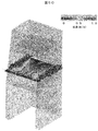
- the longitudinal cross-sectional view of the simple model for an analysis of the safety cabinet which has a front shutter rectifier of the present invention is shown.
- the analysis result of the flow of the air by the front shutter rectifier of FIG. 4A is shown.
- FIG. 5A shows an analysis result of air flow in a central vertical portion of the safety cabinet of FIG. 5A.
- the analysis result of the air flow of the center horizontal part of the safety cabinet of FIG. 5A is shown.
- the analysis result of the air flow of the front part of the safety cabinet of FIG. 5A is shown.
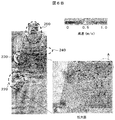
- inner side of the ceiling board of the work space upper part of this invention is shown.
- the analysis result of the air flow of the safety cabinet of FIG. 6A is shown.
- the perspective view of the safety cabinet when mounting the centrifuge of this invention is shown.
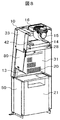
- the cross-sectional perspective view of the safety cabinet which made the front shutter which shows 2nd Embodiment of this invention movable is shown.
- cover of the centrifuge which shows 3rd Embodiment of this invention, and varies the flow volume of a fan is shown.
- the side view of the safety cabinet for demonstrating the area and the wind speed in the opening part of the working space which shows 4th Embodiment of this invention, and the slit of the side wall surface on either side is shown.
- FIG. 1 shows an external perspective view and a longitudinal sectional view of a class I type safety cabinet equipped with a centrifuge showing Embodiment 1 of the present invention
- FIG. 2 shows a front sectional view of the safety cabinet of FIG. Side surface sectional drawing is shown.
- Class I type safety cabinets generally have a structure that prevents the discharge of aerosol by injecting air from the entire opening for the purpose of protecting workers, and directly injects indoor air and exhausts HEPA filters. It is the composition which discharges through.
- the safety cabinet of the present invention shown in FIGS. 1 and 2 is an improvement based on this class I configuration.
- 10 is a safety cabinet
- 11 is a work space where an operator works
- 12 is a fixed front shutter disposed above the opening of the work space
- 13 is a tip of the fixed front shutter 12.
- the left and right walls 31 have exhaust slits
- 21 is a centrifuge disposed below the work space
- 22 is a lid of the centrifuge 21
- 23 is an infectious substance.
- Reference numeral 24 denotes a side exhaust passage disposed on the left and right sides of the work space
- 25 denotes an air flow flowing from the work space to the side exhaust passage 24 through a slit 20 (referred to as a first slit)
- 26 denotes a flow in the side exhaust passage 24.
- 27 indicates a negative pressure in the work space
- 28 indicates a slit (referred to as a second slit) disposed on the back side of the ceiling plate 41 in the work space
- 29 indicates a caster
- 30 indicates the left and right sides of the work space.
- a chamber (referred to as a first chamber) in which air exhausted from the slit 20 on the wall surface and the slit 28 on the back side of the ceiling plate 41 gathers, 31 is the left and right side wall surfaces of the work space, 32 is the air after passing through the HEPA filter 14 A chamber for exhausting air from the blower 15 (referred to as a second chamber), 33 is an upper front part of the cabinet body, 50 is a lower front part of the cabinet body, and 51 is a side part of the cabinet body.
- a first chamber in which air exhausted from the slit 20 on the wall surface and the slit 28 on the back side of the ceiling plate 41 gathers
- 31 is the left and right side wall surfaces of the work space
- 32 is the air after passing through the HEPA filter 14
- a chamber for exhausting air from the blower 15 (referred to as a second chamber)
- 33 is an upper front part of the cabinet body
- 50 is a lower front part of the cabinet body
- 51 is a side part of the cabinet body.
- a fixed front shutter 12 is disposed above the opening 18 of the work space 11, and a front shutter rectifying plate 13 is inclined to the inside of the work space at the lower end of the fixed front shutter 12. Formed and arranged.
- this front shutter rectifying plate 13 is not formed and only the fixed front shutter 12 is provided, the air inflow air 19 into the work space is along the entire peripheral side wall of the lower surface of the fixed front shutter 12 and the opening 18 of the work space. Therefore, there is a possibility that a wind speed distribution can be achieved in which the wind speed increases and the wind speed near the center of the work space 18 decreases.
- a front shutter rectifying plate 13 is disposed. This effect will be described later.
- a ceiling plate 41 is formed on the upper side of the work space 11, and a space is formed on the upper portion of the ceiling plate 41 by a ceiling surface and a surface on which the HEPA filter 14 is disposed, and a chamber for collecting air exhausted from the work space 11 30 is formed.
- the air in the chamber 30 is sucked into the HEPA filter 14 and filters dust, infectious substances 23, and the like.
- the clean air that has passed through the HEPA filter 14 is exhausted to the outside of the safety cabinet 10 by the blower 15 via the exhaust duct 16.
- a chamber 32 of clean air space in which the blower 15 is installed is formed.
- a space is formed by the left and right side wall surfaces 31 of the work space 11 and the side surface portion 51 of the safety cabinet 10, and the air in the work space 11 is caused to flow into this space to form the side exhaust flow path 24.
- Upper portions of the side exhaust passages 24 formed on the left and right sides of the work space are connected to the first chamber 30.
- the air in the work space 11 flows through the slits formed in the left and right wall surfaces of the work space and flows into the side exhaust flow path 24.
- the vertically elongated slit holes are formed in the vertical direction on the left and right side wall surfaces of the work space, but they may be punched holes or elliptical holes.
- a plurality of second slits 28 that are elongated in the width direction are arranged at the back of the ceiling plate 41 so that the air on the back side in the work space flows upward.
- the front shutter rectifying plate 13 disposed below the fixed front shutter 12 is provided to improve the wind speed distribution of the working opening 18 and has a length of 50 to 150 mm and a fixed angle of fixed. From the front shutter 12 toward the work space 11, it is fixed at an angle of 30 to 60 ° from the horizontal.
- the material may be a transparent glass surrounded by a SUS frame or a steel plate.
- left and right side slits 20 for exhaust provided in the work space 11 are directed from the front to the back of the work space 11 in order to rectify the inflow air flowing from outside the cabinet. Thus, the opening area is gradually reduced.
- a centrifuge 21 is mounted in the lower part of the work space of the safety cabinet 10. As shown in FIG. 7, the centrifuge 21 is mounted by removing the lower front plate 50 of the safety cabinet 10 and moving the centrifuge 21 with the casters 50 to the lower part of the work space. Moreover, when the lid 22 of the centrifuge is opened so that the operator can work easily, the centrifuge is installed so as to fall down on the back side of the work space. After installation, the lower front plate 50 of the safety cabinet is attached. Further, the lower front plate 50 of the cabinet 10 may be fixed by screwing on both sides or may be provided with a hinge on one side and fixed as a door. Casters 29 are provided on the legs of the safety cabinet so that they can be moved with a light force when moving.
- FIG. 3A to FIG. 3C the front shutter rectifying plate 13 is not formed, the slits 20 formed on the left and right wall surfaces 31 of the work space are arranged in three rows in the vertical direction, and the shape is an elongated vertically long hole, and the slit is arranged.
- This area is set at the approximate center of the wall, and the air flow is analyzed when the entire area is formed in a rectangular area.
- FIG. 3A shows a perspective view and a longitudinal sectional view of a simple model for analysis of a safety cabinet to be analyzed.
- the width (L2) of the cabinet is 850 mm
- the height (L1) is 1950 mm
- the depth (L3) is 780 mm
- the width (L6) of the opening in the work space is 650 mm
- the height (L5) of the opening of the space is 550 mm.
- the average wind speed is 0.5 m / s.
- the slit 20 has a configuration in which 60 holes of 100 mm ⁇ 10 mm are formed on one side.
- FIG. 3B shows the conditions to be analyzed
- FIG. 3B (a) shows the input unit representing the setting of the cross-sectional calculation
- FIG. 3B (b) shows the range to be analyzed.
- the height direction of the simplified model for analysis of the safety cabinet is the y direction
- the width direction is the x direction
- the depth direction is the z direction
- the number of cross sections is 300 in the y direction
- the z direction is 175
- the voxel size display is about 9.2 million cells
- the analysis range is a range including the entire cabinet as shown in FIG. 3B (b).
- FIG. 3C shows the air flow in the longitudinal section of the safety cabinet shown in FIG. 3A (b).
- 100 indicates the air flow below the opening of the work space
- 120 indicates the air flow in the chamber 30 above the ceiling plate 41
- 130 indicates the air flow in the exhaust chamber 32.
- the region from 100 to 130 is a portion where the wind speed is high, and in the figure, the wind speed is indicated by an arrow line, and the black bundle portion indicates that the wind speed is high.
- the air flow is about 1 m / s with respect to the average wind speed of 0.5 m / s.
- the air that has flowed in as shown by the arrows flows in from the opening and flows toward the back, and since there is no front shutter rectifying plate, it is caught at the upper end of the opening of the work space. Turbulent flow is generated, and the air is exhausted from the slits 20 on the left and right side wall surfaces.
- FIG. 4A shows a configuration in which a front shutter rectifying plate 13 is inclined at the front end of the fixed front shutter 12 and inclined toward the work space.
- the slits 20 formed on the left and right side walls in the work space are the same as in FIG. 3A, and 60 holes of 100 mm ⁇ 10 mm (both sides) are formed.
- the air flow in the configuration of FIG. 4A is shown in FIG. 4B.
- the part where the wind speed is high is a part surrounded by a circle (dotted line)
- 140 indicates the air flow below the opening of the work space
- 150 indicates the air flow above the opening of the work space.
- Reference numeral 160 denotes an air flow in the chamber 30 above the ceiling plate
- 170 denotes an air flow in the exhaust chamber 32.
- the air that flows in along the front shutter rectifying plate 13 out of the air that flows in from the opening is caught in the upper side of the work space and generates turbulent flow. That is, when the arrangement of the slits 20 on the left and right side walls is the same, and the front shutter rectifying plate 13 is arranged, the formation of the slits 20 is the same as the configuration of FIG. To do.
- the front shutter rectifying plate 13 is arranged, the slit 20 is arranged, and the flow of air when the arrangement of the slit 20 is changed is analyzed.
- the front shutter rectifying plate 13 is disposed at the front end of the fixed front shutter 12 so as to be inclined toward the working space, and the arrangement of the slits 20 formed on the left and right side wall surfaces of the working space is an extension of the front shutter rectifying plate 13.
- positioned below the direction is shown, and the flow of the air of this structure is analyzed.
- FIG. 5A shows a cross-sectional perspective view of a simplified analysis model of a safety cabinet in which the front shutter rectifying plate 13 is formed in the upper part of the opening and the slit 20 is disposed below the extending direction 40 of the front shutter rectifying plate 13.
- B shows a side view.
- the slits 20 are arranged in three rows below the extension line 40 of the front shutter rectifying plate 13, and the range of the arrangement is substantially triangular.
- FIG. 5B shows the analysis result of the air flow having the configuration shown in FIG. 5A (a).
- the part where the wind speed is high is a portion surrounded by a circle (dotted line)
- 180 indicates the air flow below the opening of the work space
- 190 indicates the air flow above the opening of the work space
- 200 indicates the air flow in the chamber 30 above the ceiling plate 41
- 210 indicates the air flow in the exhaust chamber 32.
- the slit 20 It concentrates in the slit 20 arrange
- the front shutter rectifying plate 13 is disposed on the upper side of the opening so as to be inclined inward of the work space, and the range of the slit 20 disposed on the left and right side walls of the work space is below the extension line direction of the rectifying plate 13.
- FIG. 5C shows the analysis result of the horizontal air flow in the central portion of the work space in the simplified analysis model of the safety cabinet shown in FIG. 5A.
- a large amount of air with high wind speed passes through the slit 20 from the work space and flows in the side exhaust passage 24, and the wind speed at the center is low and the wind speed on both sides is high in the work space.
- the wind speed is low on the back side of the work space, and there is a possibility that it may be hazy.
- FIG. 5D shows the analysis result of the air flow in the front central section of the working space and the exhaust part in the simplified model for analysis of the safety cabinet shown in FIG. 5A.
- the air flow in the vicinity of the center from the opening of the work space has a low wind speed at the center of the work space, the wind speed increases as it approaches the left and right side walls, and the portion where the slit 20 is located is higher. That is, although the slits 20 are arranged in three rows in the vertical direction, it can be seen that the wind speed at that portion is high. Further, in the side exhaust passage 24 and the chamber 30 on the ceiling plate, the wind speed is high, and the wind speed of the exhaust duct portion of the exhaust chamber 32 is high. Also, the wind speed at the upper center of the work space is low.
- FIG. 6A shows a longitudinal sectional perspective view and a plan view of the ceiling board 41 of a simple model for analysis of a safety cabinet in which slits 28 are arranged.
- the front shutter rectifying plate 13 is arranged above the opening of the work space
- the slit 20 is arranged below the extending line direction of the rectifying plate 13, and below the extending line direction of the rectifying plate 13.
- a plurality of slits 20 are vertically arranged on the side, the entire range of the slits is substantially triangular, and the slits 28 are arranged in the width direction on the back side of the ceiling surface 41. Further, in this configuration, the circle A is a place where air easily stagnates.
- FIG. 6B shows the analysis result of the air flow in the configuration of FIG. 6A.
- the air that has flowed in through the opening of the work space travels straight and flows through the slits 20 on the left and right side wall surfaces 31, and the air that flows in along the rectifying plate 13 flows on the slits on the left and right side wall surfaces.
- the air that flows in along the rectifying plate 13 flows on the slits on the left and right side wall surfaces.
- the stagnation is eliminated by the slit 28 arranged on the back side of the ceiling board.
- Example 2 Next, it forms so that the front shutter 80 which has arrange
- a configuration that can be adjusted is shown in FIG.
- the front shutter 80 is formed so as to be sandwiched between the upper front portion 33 and the upper front portion back plate 42 of the safety cabinet and is configured to be slidable. Further, when the worker works, the front shutter rectifying plate 13 can be made detachable so that it can be removed if it hinders the work.
- the front shutter 80 is transparent so that the work space can be seen. In the case of Example 1, since it is a fixed type, it may be opaque.
- a handle is formed in the center of the outer side of the front shutter 80 so that the operator can perform an up / down sliding operation.
- 21 is a centrifuge
- 22 is a centrifuge lid
- 60 is a sensor for detecting the opening / closing of the centrifuge lid
- 61 is a lid opening / closing sensor input circuit
- 62 is a detection for detecting the opening / closing of the lid.
- a circuit, 63 is a controller for controlling the motor
- 64 is a motor for driving the blower 15, and 15 is a blower.
- the operator puts the sample between the centrifuges, inserts the centrifuge between the rotors, opens the lid of the centrifuge, puts the rotor in the chamber of the separator, closes the lid, and turns on the SW of the centrifuge To do.
- open the centrifuge lid remove the rotor and close the lid.
- An open / close sensor 60 arranged at the lid is installed, and when the lid of the centrifuge is opened, a lid open signal is sent to the lid open / close sensor input circuit 61, and the detection circuit 62 detects that the lid has been opened.
- the motor controller 63 temporarily increases the rotating power for a predetermined time, increases the rotational speed of the motor 64, and increases the wind force of the blower 15.
- the centrifuge 21 and the safety cabinet 10 are not integrated, they are connected via a connector or wirelessly transmitted to the cabinet body to connect the sensor output.
- a sensor for detecting the opening / closing of the centrifuge lid an optical sensor is used to emit light on a part of the lid surface, receive reflection from the lid surface, and detect the opening / closing of the lid.
- switches that turn on and off at the same time, and mechanical switches such as ⁇ switches.
- Example 4 Next, the optimal area ratio and wind speed of the slit 20 of the opening surface of the safety cabinet of Example 4 of this invention and the side wall surface of the right and left of a working space are demonstrated.
- the optimum opening area of the entire slit 20 disposed on the left and right side walls of the work space is obtained.
- the resistance due to the speed change when exhausting from the work space and passing through the slit 20 in the in-machine resistance of the safety cabinet is set to 2 to 3 Pa depending on the characteristics of the blower 15. Determine to be.
- the in-machine resistance is a pressure loss where a speed change occurs in the flow path
- the pressure loss ⁇ P due to the speed change is expressed by the following equation.
- Equation 1 ⁇ ⁇ (1/2) ⁇ ⁇ ⁇ (V1 2 ⁇ V2 2 ) (Equation 1)
- ⁇ is the pressure loss coefficient
- ⁇ is the density of the fluid (1.2 for air)
- V1 is the speed before the speed changes
- V2 is the speed after the speed changes.
- the pressure loss coefficient ⁇ varies depending on the material in the flow path, the fluid velocity, etc., it may not be 1 or more in the case of a large size, so 1 may be used in the rough calculation.
- the total area S OUT of the slits 20 is 100 mm ⁇ 10 mm in the area of one slit, and 40 are arranged on one side.
- the air volume Q in the work space is usually 0.5 m / s because the velocity of the air flowing into the opening is 0.5 m / s.
- Q is 10.7 m 3 / s.
- the ratio of the wind speed of the slits on the left and right side wall surfaces in the work space to the wind speed of the air flowing into the opening is 4.4. Therefore, the ratio of the wind speed of the slits on the left and right side wall surfaces in the work space to the wind speed of the air flowing into the opening may be about four times as high.
- the wind speed distribution of the work opening 18 is improved, and an air barrier can be secured even in the case of a wide opening where the height of the work opening 18 exceeds 400 mm, thereby improving workability.
- the infectious substance 23 generated during the experiment work in a device such as a centrifuge, an analyzer, or an observer incorporated in the safety cabinet 10 is efficiently transferred from the work space 11 to the side exhaust passages 24 installed on the left and right of the work space. Discharged. Since the configuration does not exhaust from the back of the work space 11, even when a large device is mounted in the safety cabinet 10, the depth space can be minimized, the carry-in route and the installation space can be secured, and the centrifugal built into the safety cabinet 10. Even when the open / close lid 22 of the apparatus 21 such as a separator, analyzer or observer moves up and down, a stable air flow can be formed without obstructing the exhaust path so that the work can be performed with peace of mind. became.
- first chamber Between the ceiling plate and the HEPA filter Chamber (first chamber), 31... Left and right side wall surfaces of work space, 32 .. Exhaust chamber (second chamber), 40. Extension line of front shutter rectifier plate, 41. Ceiling plate of work space, Side portions of 1 .. safety cabinet, 60 .. cover opening and closing sensor of the centrifuge, 62 .. cover opening and closing sensor sensing circuit, 63 .. motor controller, for 64 .. blower motor, 80 .. movable front shutter.
Abstract
Provided is a safety cabinet configured so that an inflowing air flow is not affected by the position and size of a device mounted in a work space and by the operation of equipment, such as the operation of opening and closing the lid of a centrifugal separator. A safety cabinet is provided with a work space in which a worker works, a front face shutter which is formed at the front face of the work space, a work opening section which is located below the front face shutter and which is interconnected with the work space, and an air discharge means which sucks air from the work opening section and discharges the air within the work space by means of a blower to the outside of the safety cabinet through an air purification means. The safety cabinet is characterized in that a front face shutter flow regulation plate which is tilted toward the inside of the work space is formed on the underside of the front face shutter, that the safety cabinet is provided with left and right side wall surfaces within the work surface, that side air discharge passages are formed by the side wall surfaces and by the side surfaces of the safety cabinet, that slits are formed in the left and right side wall surfaces, and that air within the work space is sent to the side air discharge passages through the slits and discharged through the air purification means.
Description
本発明は、安全キャビネットに関し、特に、感染症の研究や医薬品の開発のために遠心分離機、分析器、観察器などの装置を安全キャビネット内に組み込み可能な安全キャビネットに関する。
The present invention relates to a safety cabinet, and more particularly, to a safety cabinet in which devices such as a centrifuge, an analyzer, and an observation device can be incorporated in the safety cabinet for infectious disease research and pharmaceutical development.
安全キャビネットは、作業空間の前面に形成された上下スライド式の前面シャッタ下方の作業開口部より安全キャビネット外の空気を吸い込むことで、エアバリアを形成し、安全キャビネットの作業空間と安全キャビネット外の雰囲気を、物理的に遮断している。作業開口部から吸い込まれた空気は、安全キャビネットの内部を通り、安全キャビネットに設置された排気用HEPAフィルタで、塵埃とともに感染物質を除去し、清浄空気として安全キャビネットの装置外に排気される。作業開口部から排気用HEPAフィルタへ空気を誘導する送風手段は、安全キャビネット装置内部に装備している場合と、安全キャビネット装置外に設置されている場合がある。
The safety cabinet forms an air barrier by sucking air outside the safety cabinet from the work opening under the front and lower slide type front shutter formed on the front of the work space, forming an air barrier, and the atmosphere outside the safety cabinet work space and the safety cabinet Is physically shut off. The air sucked from the work opening passes through the inside of the safety cabinet, and removes infectious substances together with dust by an exhaust HEPA filter installed in the safety cabinet, and is exhausted out of the safety cabinet as clean air. The air blowing means for guiding air from the work opening to the exhaust HEPA filter may be provided inside the safety cabinet device or may be installed outside the safety cabinet device.
安全キャビネットの構造による分類のバイオハザード対策用クラスIキャビネットの場合、安全キャビネット外の空気をそのまま安全キャビネットの作業空間に取り込み、作業空間上部に給気用HEPAフィルタのない構造である。作業空間で感染物質を取り扱う場合などで、作業者の安全性を確保すべき作業で、かつ無菌操作が不要な作業に使用される。以上の構成により、バイオハザード対策用クラスIキャビネットでは、作業開口部のエアバリアと排気用HEPAフィルタにより、作業空間内で取り扱う感染物質が安全キャビネット外に漏れないように構成している。
In the case of class I cabinets for biohazard measures classified according to the structure of the safety cabinet, the air outside the safety cabinet is directly taken into the work space of the safety cabinet, and there is no air supply HEPA filter at the top of the work space. Used when working with infectious substances in the work space, etc., for work that should ensure the safety of the worker and that do not require aseptic operation. With the above configuration, the biohazard class I cabinet is configured so that infectious substances handled in the work space do not leak out of the safety cabinet by the air barrier at the work opening and the exhaust HEPA filter.
安全キャビネットの作業空間内で、装置を取り扱う作業の一つに、遠心分離機の蓋を開けるという作業がある。遠心分離機内では感染性のある実験材料を、回転撹拌するので、内部では飛沫(エアロゾル)が多量に発生している状態である。さらに、遠心分離機の蓋を開ける瞬間に、内部の飛沫(エアロゾル)が遠心分離機外に放出される。このように、感染性のある飛沫(エアロゾル)が放出される可能性があるため、安全キャビネットの作業空間内で遠心分離機の蓋を開けることによる外部への感染物質の拡大を防止している。
One of the tasks to handle the device in the work space of the safety cabinet is to open the centrifuge lid. In the centrifuge, since the infectious experimental material is rotationally agitated, a large amount of droplets (aerosol) is generated inside. Furthermore, at the instant when the lid of the centrifuge is opened, internal droplets (aerosol) are discharged outside the centrifuge. In this way, infectious droplets (aerosols) may be released, preventing the spread of infectious substances to the outside by opening the centrifuge lid in the work space of the safety cabinet. .
従来技術による遠心分離機を安全キャビネットに組み込んだ構造を、特許文献1(特開2007-111596号公報)に示す。遠心分離機の回転分離槽を作業空間の下流側(下面)に配置し、実施の形態に記載のように、シャッタ下の通気孔から入った気流は、作業台下面に形成した遠心分離機下方の分離槽を囲うように流れ、リターンダクトに導かれる。この構成により、遠心分離機上方の作業空間の清浄空気を維持し、かつ、シャッタ下の通気孔によるエアバリアで、作業空間と安全キャビネット外部を隔離している。エアバリアのための気流は、作業空間下面に形成した遠心分離機下方を通り、リターンダクトに導かれている。
A structure in which a conventional centrifugal separator is incorporated in a safety cabinet is shown in Patent Document 1 (Japanese Patent Laid-Open No. 2007-111596). The centrifugal separation tank of the centrifuge is arranged on the downstream side (lower surface) of the work space, and as described in the embodiment, the airflow entering from the vent hole under the shutter is below the centrifuge formed on the work table lower surface. It flows so as to surround the separation tank and is led to the return duct. With this configuration, clean air in the work space above the centrifuge is maintained, and the work space and the outside of the safety cabinet are isolated by an air barrier formed by a vent hole under the shutter. The airflow for the air barrier passes through the lower part of the centrifuge formed on the lower surface of the work space and is guided to the return duct.
前記従来技術の遠心分離機を組み込んだ安全キャビネットを特許文献1(特開2007-111596号公報)に示す。文献1には、作業空間下面の作業台面に蓋を形成し、その下方に遠心分離機の分離槽を形成している。作業空間から降りてきた気流は、作業空間の通気孔、作業台面と遠心分離機分離槽の間の空間、シャッタ下の通気孔の3箇所から吸い込まれ、リターンダクトに導かれている。シャッタ下の通気孔から吸い込まれた気流は、遠心分離機の分離槽下方のリターンダクトを通り、送風機に導かれる。この構成により、作業空間の清浄気流である清浄度を維持しつつ、シャッタ下の気流により、作業空間と安全キャビネット外の空間を、物理的に隔離している。
A safety cabinet incorporating the above-described conventional centrifugal separator is shown in Patent Document 1 (Japanese Patent Laid-Open No. 2007-111596). In Document 1, a lid is formed on the work table surface on the lower surface of the work space, and a separation tank of a centrifuge is formed below the cover. The airflow that has come down from the work space is sucked from three places: a vent hole in the work space, a space between the work table surface and the centrifuge separation tank, and a vent hole under the shutter and led to the return duct. The airflow sucked from the vent hole under the shutter passes through the return duct below the separation tank of the centrifuge and is guided to the blower. With this configuration, the work space and the space outside the safety cabinet are physically separated by the airflow under the shutter while maintaining the cleanliness that is the clean airflow in the work space.
従来技術による遠心分離機を組み込んだ安全キャビネットでは、シャッタ下方から吸い込んだ気流が、遠心分離機の下方を通り、リターンダクトに導かれるため作業台面の遠心分離機位置が変わると、シャッタ下方から吸い込まれる気流の状態が変わる可能性がある。
In a safety cabinet incorporating a centrifuge according to the prior art, the airflow sucked from the lower part of the shutter passes through the lower part of the centrifuge and is guided to the return duct. Therefore, if the centrifuge position on the work surface changes, the air is sucked from the lower part of the shutter. There is a possibility that the state of airflow will change.
また、遠心分離機の分離槽が大きい容量のものや自立型の遠心分離機を導入したい場合、シャッタ下方から吸い込まれた気流が、キャビネットに組み込んだ装置が障害となり、効率よく排気されずエアバリアを形成できない可能性があり、かつシャッタ開口部高さが200mm程度で小さいため、大きな遠心分離機の蓋を開ける作業では、作業性が非常に悪かった。
Also, if you want to introduce a centrifugal separator with a large capacity or a free-standing centrifugal separator, the airflow drawn from the bottom of the shutter becomes an obstacle to the device built into the cabinet, and the air barrier is not efficiently exhausted. There is a possibility that it cannot be formed, and since the height of the shutter opening is as small as about 200 mm, the workability is very poor in the operation of opening the lid of a large centrifuge.
安全キャビネットの場合、日本工業規格 JIS K3800 バイオハザード対策用クラスIIキャビネットに記載のように、気流の状態が変わった場合、枯草菌芽胞を使用した物理的隔離性能を再び評価する必要がある。クラスIキャビネットにおいては、上記規格の作業者の安全性に関する気流バランス性能を評価する必要がある。
In the case of a safety cabinet, it is necessary to re-evaluate the physical isolation performance using Bacillus subtilis spores when the airflow state changes as described in Japanese Industrial Standards JIS K3800 Biohazard Class II Cabinet. In a class I cabinet, it is necessary to evaluate the airflow balance performance related to the safety of the operator of the above standard.
本発明の目的は、安全キャビネットにおいて、作業空間に組み込む装置の位置、大きさ、機器の操作、例えば遠心分離機のような蓋を開閉する操作により流入気流が影響されない安全キャビネットを提供することにある。
An object of the present invention is to provide a safety cabinet in which the inflow airflow is not affected by the position, size, and operation of the device incorporated in the work space, for example, the operation of opening and closing a lid such as a centrifuge. is there.
また、感染性のある材料が作業空間に淀まないことを重要な機能とする安全キャビネットにおいて、作業空間で発生した感染性のある飛沫(エアロゾル)が作業空間に滞留することが無く、最短距離で排気することが可能な安全キャビネットを提供できる。
Also, in a safety cabinet that has an important function of preventing infectious materials from entering the work space, the infectious spray (aerosol) generated in the work space does not stay in the work space, and is the shortest distance. Can provide a safety cabinet that can be evacuated.
作業開口が400mm以上と広い場合、開口部中央付近の風速が遅くなるので、エアバリアを確保するには、上下スライド式の前面シャッタ構造とし、作業時は作業開口を200mm程度に設定するか、作業開口部全体の風速を上げる必要があり、排気ファンの排気風量が上がるとともに建物の熱負荷が大きくなる。
When the work opening is wide as 400 mm or more, the wind speed near the center of the opening becomes slow. To secure an air barrier, a front shutter structure with a vertical slide type is used, and the work opening is set to about 200 mm during work or It is necessary to increase the wind speed of the entire opening, which increases the exhaust air volume of the exhaust fan and increases the heat load of the building.
本発明の他の目的は、作業開口部の風速分布を改善し、スライド式の前面シャッタを不要とし、必要最小限の風速でエアバリアを確保することにより、消費電力を抑制し、建物の熱負荷を抑制することにある。また、例えば、遠心分離機等の組み込み装置の蓋を開けた状態でも安全キャビネットの基本性能が影響されない気流構成を提供することにある。
Another object of the present invention is to improve the wind speed distribution in the work opening, eliminate the need for a sliding front shutter, and secure an air barrier with the minimum necessary wind speed, thereby reducing power consumption and building thermal load. It is to suppress. Another object of the present invention is to provide an airflow configuration in which the basic performance of the safety cabinet is not affected even when the lid of an embedded device such as a centrifuge is opened.
上記目的を達成するために、本発明は、作業者が作業をする作業空間と、該作業空間の前面に形成する前面シャッタと、該前面シャッタ下部の前記作業空間に連接する作業開口部と、該作業開口部から空気を吸い込み、前記作業空間の空気を空気清浄手段を介して安全キャビネット外へ送風機により排気する排気手段と、を有する安全キャビネットであって、前記作業開口部の上方の前面シャッタを固定し、該前面シャッタの下側に前記作業空間の内側方向に傾斜した前面シャッタ整流板を形成し、前記作業空間内の左右の側壁面を設け、該側壁面と前記安全キャビネットの側面とで側面排気流路を形成し、前記左右の側壁面に第1のスリット又はパンチング孔を形成し、前記作業空間の空気を該スリット又はパンチング孔を介して前記側面排気流路に送り、前記空気清浄手段を介して排気することを特徴とする。
In order to achieve the above object, the present invention provides a work space where an operator works, a front shutter formed on the front surface of the work space, a work opening connected to the work space below the front shutter, A front cabinet above the work opening, comprising: a safety cabinet having a suction unit for sucking air from the work opening and exhausting the air in the work space to the outside of the safety cabinet by a blower through an air cleaning unit. A front shutter rectifying plate inclined inward of the work space is formed below the front shutter, and left and right side wall surfaces in the work space are provided, and the side wall surface and the side surface of the safety cabinet are provided. A side exhaust flow path is formed, first slits or punching holes are formed in the left and right side wall surfaces, and air in the working space is passed through the slits or punching holes to the side. Feeding the exhaust passage, and wherein the evacuating via said air cleaning unit.
また、上記安全キャビネットにおいて、前記前面シャッタ整流板の延長線方向の下側に、前記第1のスリット又はパンチング孔を形成することを特徴とする。
In the safety cabinet, the first slit or the punching hole is formed below the front shutter rectifying plate in the extension line direction.
また、上記安全キャビネットにおいて、前記作業空間の天井板と前記空気清浄手段のHEPAフィルタとの間にチャンバを設け、前記側面排気流路は該チャンバに接続され、前記天井板の奥側に横方向に第2のスリットを形成したことを特徴とする。
Further, in the safety cabinet, a chamber is provided between the ceiling plate of the work space and the HEPA filter of the air cleaning means, the side exhaust flow path is connected to the chamber, and laterally extends to the back side of the ceiling plate. The second slit is formed in the above.
本発明によれば、安全キャビネットの作業空間内に、分析器や観察器などの装置を組み込み、配置したり固定したりした場合、作業開口部に形成される吸い込み気流(流入気流)の風速及び気流の状態が、装置の位置、大きさ、機器の操作、例えば遠心分離機のような蓋を開閉する操作により流入気流が影響されない安全キャビネットを提供できる。
According to the present invention, when a device such as an analyzer or an observation device is installed in a work space of a safety cabinet, and placed or fixed, the wind speed of the suction airflow (inflow airflow) formed in the work opening and It is possible to provide a safety cabinet in which the inflow airflow is not affected by the position of the airflow, the position of the apparatus, the operation of the device, for example, the operation of opening and closing a lid such as a centrifuge.
また、感染性のある材料が作業空間に滞留しないことを重要な機能とする安全キャビネットにおいて、作業空間で発生した感染性のある飛沫(エアロゾル)が、作業空間に滞留することなく最短距離で排気することが可能な安全キャビネットを提供できる。
Also, in a safety cabinet that has an important function of preventing infectious materials from staying in the work space, infectious sprays (aerosols) generated in the work space are exhausted at the shortest distance without staying in the work space. Can provide a safety cabinet that can be done.
以下、本発明の実施の形態を、図を用いて説明する。
(実施例1)
図1は、本発明の実施例1を示す遠心分離機を搭載したクラスIタイプの安全キャビネットの外観斜視図及びその縦断面図を示し、図2は、図1の安全キャビネットの正面断面図及び側面断面図を示す。クラスIタイプの安全キャビネットは、一般に作業者の保護を目的に、全面開口部から空気を流入させてエアロゾルの排出を防止する構造となっており、室内の空気を直接流入し、排気はHEPAフィルタを通して排出する構成である。図1、図2に示す本発明の安全キャビネットは、このクラスIの構成をベースにし改良したものである。 Hereinafter, embodiments of the present invention will be described with reference to the drawings.
(Example 1)
FIG. 1 shows an external perspective view and a longitudinal sectional view of a class I type safety cabinet equipped with a centrifuge showing Embodiment 1 of the present invention, and FIG. 2 shows a front sectional view of the safety cabinet of FIG. Side surface sectional drawing is shown. Class I type safety cabinets generally have a structure that prevents the discharge of aerosol by injecting air from the entire opening for the purpose of protecting workers, and directly injects indoor air and exhausts HEPA filters. It is the composition which discharges through. The safety cabinet of the present invention shown in FIGS. 1 and 2 is an improvement based on this class I configuration.
図1及び図2において、10は安全キャビネット、11は作業者が作業する作業空間、12は作業空間の開口部の上側に配置された固定式前面シャッタ、13は固定式前面シャッタ12の先端に配置された前面シャッタ整流板、14はHEPAフィルタ、15は送風機、16は排気ダクト、17は排気の気流、18は作業空間の開口部、19は安全キャビネット外部から入る流入気流、20は作業空間の左右壁31に配置した排気用スリット、21は作業空間の下側に配置した遠心分離機、22は遠心分離機21の蓋、23は感染物質を示す。24は作業空間の左右に配置した側面排気通路、25は作業空間から側面排気通路24にスリット20(第1のスリットという)を介して流れる空気の流れで、26は側面排気通路24内を流れる空気の流れを示す。27は作業空間内が負圧であることを示し、28は作業空間の天井板41の奥側に配置したスリット(第2のスリットという)、29はキャスタで、30は作業空間の左右の側壁面のスリット20及び天井板41の奥側のスリット28より排気される空気が集まるチャンバ(第1のチャンバという)、31は作業空間の左右の側壁面、32はHEPAフィルタ14通過後の空気を送風機15により排気するためのチャンバ(第2のチャンバという)で、33はキャビネット本体の上部前面部、50はキャビネット本体の下部前面部、51はキャビネット本体の側面部である。
1 and 2, 10 is a safety cabinet, 11 is a work space where an operator works, 12 is a fixed front shutter disposed above the opening of the work space, and 13 is a tip of the fixed front shutter 12. Arranged front shutter rectifier plate, 14 HEPA filter, 15 blower, 16 exhaust duct, 17 exhaust airflow, 18 opening of work space, 19 incoming airflow from outside of safety cabinet, 20 work space The left and right walls 31 have exhaust slits, 21 is a centrifuge disposed below the work space, 22 is a lid of the centrifuge 21, and 23 is an infectious substance. Reference numeral 24 denotes a side exhaust passage disposed on the left and right sides of the work space, 25 denotes an air flow flowing from the work space to the side exhaust passage 24 through a slit 20 (referred to as a first slit), and 26 denotes a flow in the side exhaust passage 24. Shows air flow. 27 indicates a negative pressure in the work space, 28 indicates a slit (referred to as a second slit) disposed on the back side of the ceiling plate 41 in the work space, 29 indicates a caster, and 30 indicates the left and right sides of the work space. A chamber (referred to as a first chamber) in which air exhausted from the slit 20 on the wall surface and the slit 28 on the back side of the ceiling plate 41 gathers, 31 is the left and right side wall surfaces of the work space, 32 is the air after passing through the HEPA filter 14 A chamber for exhausting air from the blower 15 (referred to as a second chamber), 33 is an upper front part of the cabinet body, 50 is a lower front part of the cabinet body, and 51 is a side part of the cabinet body.
次に、本発明の安全キャビネットの構成について説明する。図1及び図2において、作業空間11の開口部18の上部に固定式前面シャッタ12を配置し、固定式前面シャッタ12の下側先端には、前面シャッタ整流板13を作業空間内側に傾斜させて形成し配置している。この前面シャッタ整流板13を形成せず、固定式前面シャッタ12のみの場合、作業空間への空気の流入気流19は固定式前面シャッタ12の下面と作業空間の開口部18の全周側壁に沿って風速が高くなり、作業空間18の中央付近の風速が低くなるという風速分布ができる可能性がある。この風速分布におけるアンバランスを解消するため、前面シャッタ整流板13を配置している。この効果については後で説明する。
Next, the configuration of the safety cabinet of the present invention will be described. 1 and 2, a fixed front shutter 12 is disposed above the opening 18 of the work space 11, and a front shutter rectifying plate 13 is inclined to the inside of the work space at the lower end of the fixed front shutter 12. Formed and arranged. When this front shutter rectifying plate 13 is not formed and only the fixed front shutter 12 is provided, the air inflow air 19 into the work space is along the entire peripheral side wall of the lower surface of the fixed front shutter 12 and the opening 18 of the work space. Therefore, there is a possibility that a wind speed distribution can be achieved in which the wind speed increases and the wind speed near the center of the work space 18 decreases. In order to eliminate this imbalance in the wind speed distribution, a front shutter rectifying plate 13 is disposed. This effect will be described later.
作業空間11の上側には、天井板41を形成し、天井板41の上部には天井面とHEPAフィルタ14を配置する面とで空間を形成し、作業空間11から排気される空気を集めるチャンバ30を形成する。チャンバ30内の空気は、HEPAフィルタ14に吸い込まれ、塵埃や感染物質23などをろ過する。HEPAフィルタ14を通過した清浄空気は、送風機15により排気ダクト16を介して安全キャビネット10の外部へ排気される。この送風機15が設置された清浄空気の空間のチャンバ32を形成する。
A ceiling plate 41 is formed on the upper side of the work space 11, and a space is formed on the upper portion of the ceiling plate 41 by a ceiling surface and a surface on which the HEPA filter 14 is disposed, and a chamber for collecting air exhausted from the work space 11 30 is formed. The air in the chamber 30 is sucked into the HEPA filter 14 and filters dust, infectious substances 23, and the like. The clean air that has passed through the HEPA filter 14 is exhausted to the outside of the safety cabinet 10 by the blower 15 via the exhaust duct 16. A chamber 32 of clean air space in which the blower 15 is installed is formed.
また、作業空間11の左右の側壁面31と安全キャビネット10の側面部51とで空間を形成し、作業空間11内の空気をこの空間に流し、側面排気流路24を形成する。作業空間の左右に形成された側面排気流路24の上部は第1のチャンバ30に接続される。また、作業空間11内の空気は、作業空間の左右の壁面に形成したスリットを通過して側面排気流路24に流れる。なお、図1及び図2には、作業空間の左右の側壁面に垂直方向に細長い縦長のスリットの孔を形成しているが、パンチング孔でも楕円形の孔でも構わない。また、天井板41の奥の方には幅方向に細長い第2のスリット28を複数個配置し、作業空間内の奥側の空気が上方に流れるように形成している。
Further, a space is formed by the left and right side wall surfaces 31 of the work space 11 and the side surface portion 51 of the safety cabinet 10, and the air in the work space 11 is caused to flow into this space to form the side exhaust flow path 24. Upper portions of the side exhaust passages 24 formed on the left and right sides of the work space are connected to the first chamber 30. Further, the air in the work space 11 flows through the slits formed in the left and right wall surfaces of the work space and flows into the side exhaust flow path 24. In FIG. 1 and FIG. 2, the vertically elongated slit holes are formed in the vertical direction on the left and right side wall surfaces of the work space, but they may be punched holes or elliptical holes. Further, a plurality of second slits 28 that are elongated in the width direction are arranged at the back of the ceiling plate 41 so that the air on the back side in the work space flows upward.
固定式前面シャッタ12の下方に配置されている前面シャッタ整流板13は、作業開口部18の風速分布を改善するために設けられたものであり、長さは50~150mm、固定角度は、固定式前面シャッタ12から作業空間11に向かって、水平から30~60°傾けて固定されている。材質は、透明ガラスにSUS製のフレームで囲まれたもの、または鋼板製でも良い。また、前面シャッタ整流板4の延長線上に沿って、作業空間11に設けられた排気用の左右側面スリット20は、キャビネット外から入る流入気流を整流するために作業空間11の前方から背面に向かって徐々に開口面積が小さくなっている構造である。
The front shutter rectifying plate 13 disposed below the fixed front shutter 12 is provided to improve the wind speed distribution of the working opening 18 and has a length of 50 to 150 mm and a fixed angle of fixed. From the front shutter 12 toward the work space 11, it is fixed at an angle of 30 to 60 ° from the horizontal. The material may be a transparent glass surrounded by a SUS frame or a steel plate. Further, along the extension line of the front shutter rectifying plate 4, left and right side slits 20 for exhaust provided in the work space 11 are directed from the front to the back of the work space 11 in order to rectify the inflow air flowing from outside the cabinet. Thus, the opening area is gradually reduced.
また、安全キャビネット10の作業空間内の下部には、遠心分離機21を搭載する。遠心分離機21の搭載は、図7に示すように安全キャビネット10の下部前面板50を外し、キャスタ50の付いた遠心分離機21を作業空間の下部まで移動して設置、固定する。また作業者が作業し易いように遠心分離機の蓋22を開けたとき、作業空間の奥側に倒れるように設置する。設置後は、安全キャビネットの下部前面板50を取り付ける。また、キャビネット10の下部前面板50は、両側をねじ留めして固定しても、片側にヒンジを設け、扉として固定しても良い。安全キャビネットの脚部にはキャスタ29を設け、移動時に軽い力で動かせるようにしている。
Also, a centrifuge 21 is mounted in the lower part of the work space of the safety cabinet 10. As shown in FIG. 7, the centrifuge 21 is mounted by removing the lower front plate 50 of the safety cabinet 10 and moving the centrifuge 21 with the casters 50 to the lower part of the work space. Moreover, when the lid 22 of the centrifuge is opened so that the operator can work easily, the centrifuge is installed so as to fall down on the back side of the work space. After installation, the lower front plate 50 of the safety cabinet is attached. Further, the lower front plate 50 of the cabinet 10 may be fixed by screwing on both sides or may be provided with a hinge on one side and fixed as a door. Casters 29 are provided on the legs of the safety cabinet so that they can be moved with a light force when moving.
次に、本発明の安全キャビネットの構成において、空気の流れについてボクセル解析した結果について説明する。先ず、図3A~図3Cにおいて、前面シャッタ整流板13は形成しないで、作業空間の左右壁面31に形成したスリット20を垂直方向に3列として、その形状は細長い縦長の孔で、スリットを配置した領域は壁面のほぼ中央とし、全体が矩形の範囲に形成した場合の空気の流れを解析する。
Next, the result of the voxel analysis of the air flow in the configuration of the safety cabinet of the present invention will be described. First, in FIG. 3A to FIG. 3C, the front shutter rectifying plate 13 is not formed, the slits 20 formed on the left and right wall surfaces 31 of the work space are arranged in three rows in the vertical direction, and the shape is an elongated vertically long hole, and the slit is arranged. This area is set at the approximate center of the wall, and the air flow is analyzed when the entire area is formed in a rectangular area.
図3Aは、解析する安全キャビネットの解析用簡易モデルの斜視図及びその縦断面図を示す。図3Aの安全キャビネットの解析用簡易モデルにおいて、キャビネットの横幅(L2)は850mm、高さ(L1)は1950mm、奥行(L3)は780mm、作業空間の開口部の幅(L6)は650mm、作業空間の開口部の高さ(L5)は550mmとしている。また、平均風速は0.5m/sである。また、スリット20は、100mm×10mmの孔を片側に60個形成した構成である。
FIG. 3A shows a perspective view and a longitudinal sectional view of a simple model for analysis of a safety cabinet to be analyzed. In the simplified model for analysis of the safety cabinet shown in FIG. 3A, the width (L2) of the cabinet is 850 mm, the height (L1) is 1950 mm, the depth (L3) is 780 mm, the width (L6) of the opening in the work space is 650 mm, the work The height (L5) of the opening of the space is 550 mm. The average wind speed is 0.5 m / s. The slit 20 has a configuration in which 60 holes of 100 mm × 10 mm are formed on one side.
また、図3Aに示した解析用簡易モデルを解析する条件を図3Bに示す。図3Bは解析する条件を示し、図3B(a)は断面計算の設定を表す入力部を示し、図3B(b)は解析する範囲を示している。図3B(a)において、安全キャビネットの解析用簡易モデルの高さ方向をy方向、幅方向をx方向、奥行方向をz方向とすると、y方向に断面数を300とし、z方向を175、x方向を175に分割して解析とすると、ボクセルサイズ表示は約920万セルとなり、解析範囲は図3B(b)に示すようにキャビネット全体を包括する範囲である。
Moreover, the conditions for analyzing the simple model for analysis shown in FIG. 3A are shown in FIG. 3B. FIG. 3B shows the conditions to be analyzed, FIG. 3B (a) shows the input unit representing the setting of the cross-sectional calculation, and FIG. 3B (b) shows the range to be analyzed. In FIG. 3B (a), when the height direction of the simplified model for analysis of the safety cabinet is the y direction, the width direction is the x direction, and the depth direction is the z direction, the number of cross sections is 300 in the y direction, the z direction is 175, When analysis is performed by dividing the x direction into 175, the voxel size display is about 9.2 million cells, and the analysis range is a range including the entire cabinet as shown in FIG. 3B (b).
上記の解析条件により解析した結果を図3Cに示す。図3Cは、図3A(b)に示す安全キャビネットの縦断面の部分の空気の流れを示す。図3Cにおいて、100は作業空間の開口部の下側の空気の流れを示し、120は天井板41上部のチャンバ30の空気の流れを示し、130は排気用チャンバ32の空気の流れを示す。この100~130の領域が風速の高い部分で、図では風速を矢印の線で表しており、黒い束となっている部分は風速が高いことを表している。そして、この図において、平均風速0.5m/sに対し、1m/s程度の空気の流れである。また、作業空間内において、矢印で表しているように流入した空気は、開口部より流入し奥の方へ流れ、前面シャッタ整流板を有していないため作業空間の開口部上側端部で巻き込むように流れたりして乱流を生じて、左右の側壁面のスリット20より排気される。
The result of analysis under the above analysis conditions is shown in FIG. 3C. FIG. 3C shows the air flow in the longitudinal section of the safety cabinet shown in FIG. 3A (b). In FIG. 3C, 100 indicates the air flow below the opening of the work space, 120 indicates the air flow in the chamber 30 above the ceiling plate 41, and 130 indicates the air flow in the exhaust chamber 32. The region from 100 to 130 is a portion where the wind speed is high, and in the figure, the wind speed is indicated by an arrow line, and the black bundle portion indicates that the wind speed is high. In this figure, the air flow is about 1 m / s with respect to the average wind speed of 0.5 m / s. Also, in the work space, the air that has flowed in as shown by the arrows flows in from the opening and flows toward the back, and since there is no front shutter rectifying plate, it is caught at the upper end of the opening of the work space. Turbulent flow is generated, and the air is exhausted from the slits 20 on the left and right side wall surfaces.
次に、前面シャッタ整流板13を配置したときの空気の流れについて解析する。図4Aは、固定式前面シャッタ12の先端に前面シャッタ整流板13を作業空間側に傾斜して配置した構成を示す。作業空間内の左右の側壁に形成したスリット20は、図3Aと同じで、100mm×10mmの孔を60個(両側)形成している。この図4Aの構成における空気の流れを図4Bに示す。図4Bにおいて、風速が高い箇所は丸(点線)で囲んだ部分で、140は作業空間の開口部の下側の空気の流れを示し、150は作業空間の開口部の上側の空気の流れを示し、160は天井板上部のチャンバ30の空気の流れで、170は排気用のチャンバ32の空気の流れを示す。
Next, the flow of air when the front shutter rectifying plate 13 is arranged will be analyzed. FIG. 4A shows a configuration in which a front shutter rectifying plate 13 is inclined at the front end of the fixed front shutter 12 and inclined toward the work space. The slits 20 formed on the left and right side walls in the work space are the same as in FIG. 3A, and 60 holes of 100 mm × 10 mm (both sides) are formed. The air flow in the configuration of FIG. 4A is shown in FIG. 4B. In FIG. 4B, the part where the wind speed is high is a part surrounded by a circle (dotted line), 140 indicates the air flow below the opening of the work space, and 150 indicates the air flow above the opening of the work space. Reference numeral 160 denotes an air flow in the chamber 30 above the ceiling plate, and 170 denotes an air flow in the exhaust chamber 32.
また、作業空間内において、開口部より流入した空気のうち前面シャッタ整流板13に沿って流入した空気は、作業空間の上側に巻き込まれ、乱流を生じる。すなわち、左右の側面壁のスリット20の配置を同じとし、前面シャッタ整流板13を配置した場合、スリット20の形成が図3Aの構成と同じであるため作業空間における空気の流れはほぼ同じと判断する。
Also, in the work space, the air that flows in along the front shutter rectifying plate 13 out of the air that flows in from the opening is caught in the upper side of the work space and generates turbulent flow. That is, when the arrangement of the slits 20 on the left and right side walls is the same, and the front shutter rectifying plate 13 is arranged, the formation of the slits 20 is the same as the configuration of FIG. To do.
次に、前面シャッタ整流板13を配置し、スリット20を配置し、スリット20の配置を変えたときの空気の流れについて解析する。図5Aは、固定式前面シャッタ12の先端に前面シャッタ整流板13を作業空間側に傾斜して配置し、作業空間の左右の側壁面に形成したスリット20の配置を前面シャッタ整流板13の延長方向より下側に配置した構成を示し、この構成の空気の流れを解析する。
Next, the front shutter rectifying plate 13 is arranged, the slit 20 is arranged, and the flow of air when the arrangement of the slit 20 is changed is analyzed. In FIG. 5A, the front shutter rectifying plate 13 is disposed at the front end of the fixed front shutter 12 so as to be inclined toward the working space, and the arrangement of the slits 20 formed on the left and right side wall surfaces of the working space is an extension of the front shutter rectifying plate 13. The structure arrange | positioned below the direction is shown, and the flow of the air of this structure is analyzed.
図5Aは、前面シャッタ整流板13を開口部上部に形成し、前面シャッタ整流板13の延長方向40の下側にスリット20を配置した安全キャビネットの解析簡易モデルの断面斜視図を示し、図5A(b)は側面図を示す。図5A(b)に示すように、スリット20は前面シャッタ整流板13の延長線40の下側に3列配置し、その配置の範囲は略三角形である。
5A shows a cross-sectional perspective view of a simplified analysis model of a safety cabinet in which the front shutter rectifying plate 13 is formed in the upper part of the opening and the slit 20 is disposed below the extending direction 40 of the front shutter rectifying plate 13. (B) shows a side view. As shown in FIG. 5A (b), the slits 20 are arranged in three rows below the extension line 40 of the front shutter rectifying plate 13, and the range of the arrangement is substantially triangular.
図5A(a)に示した構成の空気の流れの解析結果を図5Bに示す。 図5Bにおいて、風速が高い部分は、丸(点線)で囲んだ箇所で、180は作業空間の開口部の下側の空気の流れを示し、190は作業空間の開口部の上側の空気の流れを示し、200は天井板41上部のチャンバ30の空気の流れを示し、210は排気用チャンバ32の空気の流れを示す。また、この構成において、作業空間内の空気の流れをみると、開口部より流入した空気の中で前面シャッタ整流板13に沿って流入した空気は、上側への巻き込まれは小さく、前面シャッタ整流板13の延長線方向の下側に配置したスリット20に集中し、排気される。そして、図4Bのスリット20全体の配置が矩形状の場合の空気の流れと比較すると、図5Bのスリット20全体の配置が整流板13の延長線より下側に配置し、略三角形の空気の流れの場合の方がスリット20における風速が高くなっている。
FIG. 5B shows the analysis result of the air flow having the configuration shown in FIG. 5A (a). In FIG. 5B, the part where the wind speed is high is a portion surrounded by a circle (dotted line), 180 indicates the air flow below the opening of the work space, and 190 indicates the air flow above the opening of the work space. 200 indicates the air flow in the chamber 30 above the ceiling plate 41, and 210 indicates the air flow in the exhaust chamber 32. Further, in this configuration, when the flow of air in the work space is viewed, the air that flows in along the front shutter rectifying plate 13 out of the air that flows in from the opening portion is hardly entangled upward, and the front shutter rectification is performed. It concentrates in the slit 20 arrange | positioned on the lower side of the extension line direction of the board 13, and is exhausted. 4B, the overall arrangement of the slit 20 in FIG. 5B is arranged below the extension line of the rectifying plate 13, and the substantially triangular air flow is compared with the flow of air when the entire arrangement of the slit 20 in FIG. 4B is rectangular. In the case of the flow, the wind speed in the slit 20 is higher.
このように、開口部の上側に前面シャッタ整流板13を作業空間の内側に傾斜して配置し、作業空間の左右の側面壁に配置するスリット20の範囲を整流板13の延長線方向の下側にし、スリット20の配置全体を略三角形状にする構成で、遠心分離機の蓋を開けたときエアロゾルの開口部からの放出を防止できる。
In this manner, the front shutter rectifying plate 13 is disposed on the upper side of the opening so as to be inclined inward of the work space, and the range of the slit 20 disposed on the left and right side walls of the work space is below the extension line direction of the rectifying plate 13. With the configuration in which the entire arrangement of the slits 20 is substantially triangular, the aerosol can be prevented from being released from the opening when the centrifuge lid is opened.
次に、図5Aに示した安全キャビネットの解析簡易モデルにおける作業空間の中央部の水平方向の空気の流れの解析結果を図5Cに示す。図5Cにおいて、作業空間からスリット20を通過し、側面排気流路24内を風速の高い空気が多く流れ、作業空間内は中央の風速が低く、両側の風速が高くなっている。また、作業空間の奥側は風速が低く、淀む可能性がある。
Next, FIG. 5C shows the analysis result of the horizontal air flow in the central portion of the work space in the simplified analysis model of the safety cabinet shown in FIG. 5A. In FIG. 5C, a large amount of air with high wind speed passes through the slit 20 from the work space and flows in the side exhaust passage 24, and the wind speed at the center is low and the wind speed on both sides is high in the work space. In addition, the wind speed is low on the back side of the work space, and there is a possibility that it may be hazy.
次に、図5Aに示した安全キャビネットの解析用簡易モデルにおける作業空間及び排気の部分の正面中央断面における空気の流れの解析結果を図5Dに示す。図5Dにおいて、作業空間の開口部から中央付近の空気の流れは作業空間の中央の風速が低く、左右の側壁に近づくにつれて風速は高くなり、スリット20のある箇所はさらに高くなっている。すなわち、スリット20を3列垂直方向に配置しているが、その部分の風速が高いことが分かる。また、側面排気流路24及び天井板上のチャンバ30内は、風速が高く、排気用のチャンバ32の排気ダクトの部分の風速が高い。また、作業空間の中央上部の風速は低い。
Next, FIG. 5D shows the analysis result of the air flow in the front central section of the working space and the exhaust part in the simplified model for analysis of the safety cabinet shown in FIG. 5A. In FIG. 5D, the air flow in the vicinity of the center from the opening of the work space has a low wind speed at the center of the work space, the wind speed increases as it approaches the left and right side walls, and the portion where the slit 20 is located is higher. That is, although the slits 20 are arranged in three rows in the vertical direction, it can be seen that the wind speed at that portion is high. Further, in the side exhaust passage 24 and the chamber 30 on the ceiling plate, the wind speed is high, and the wind speed of the exhaust duct portion of the exhaust chamber 32 is high. Also, the wind speed at the upper center of the work space is low.
次に、作業空間の上部に配置した天井板41の奥側にスリット28を配置した場合の空気の流れについて解析し、その解析結果について説明する。図6Aは、スリット28を配置した安全キャビネットの解析用簡易モデルの縦断面斜視図及び天井板41の平面図を示す。この解析用簡易モデルは、作業空間の開口部上部に前面シャッタ整流板13を配置し、整流板13の延長線方向より下側にスリット20を配置し、この整流板13の延長線方向より下側に複数のスリット20を縦に3列配置し、スリット全体の範囲を略三角形状とし、天井面41の奥側に幅方向にスリット28を配置した構成である。また、この構成で丸Aの部分が空気が淀み易い箇所である。
Next, the flow of air when the slit 28 is arranged on the back side of the ceiling plate 41 arranged at the upper part of the work space will be analyzed, and the analysis result will be described. FIG. 6A shows a longitudinal sectional perspective view and a plan view of the ceiling board 41 of a simple model for analysis of a safety cabinet in which slits 28 are arranged. In this simple model for analysis, the front shutter rectifying plate 13 is arranged above the opening of the work space, the slit 20 is arranged below the extending line direction of the rectifying plate 13, and below the extending line direction of the rectifying plate 13. A plurality of slits 20 are vertically arranged on the side, the entire range of the slits is substantially triangular, and the slits 28 are arranged in the width direction on the back side of the ceiling surface 41. Further, in this configuration, the circle A is a place where air easily stagnates.
この図6Aの構成における空気の流れの解析結果を図6Bに示す。図6Bにおいて、作業空間の開口部より流入した空気は、直進し、左右の側壁面31のスリット20より排気する流れがあり、整流板13に沿って流入する空気は、左右の側壁面のスリット20の方向に向かうものと、作業空間の天井板の奥側のスリット28に向かうものが存在することが分かる。そして、作業空間の奥側上方に空気が淀み易かったが、天井板の奥側に配置したスリット28により淀みは解消されている。
FIG. 6B shows the analysis result of the air flow in the configuration of FIG. 6A. In FIG. 6B, the air that has flowed in through the opening of the work space travels straight and flows through the slits 20 on the left and right side wall surfaces 31, and the air that flows in along the rectifying plate 13 flows on the slits on the left and right side wall surfaces. It can be seen that there are those heading toward the direction 20 and those heading toward the slit 28 on the back side of the ceiling plate of the work space. And although air was easy to stagnate above the back side of the work space, the stagnation is eliminated by the slit 28 arranged on the back side of the ceiling board.
(実施例2)
次に、本発明の実施例2の前面シャッタ整流板13を先端に配置した前面シャッタ80を上下にスライドできるように形成し、作業者が安全キャビネットの開口部の高さを作業内容に応じて調整できる構成を図8に示す。 図8において、前面シャッタ80は、安全キャビネットの上部前面部33と上部前面部裏板42とで挟むように形成し、スライドできる構成とする。また、作業者が作業する際、前面シャッタ整流板13が作業の妨げになる場合は外すことができるように着脱自在にすることもできる。また、前面シャッタ80は作業空間内が見えるように透明とする。実施例1の場合においては固定式にしているため不透明でも良い。また、前面シャッタ80の外側の中央には作業者の手で上下スライド操作ができるように取手を形成する。 (Example 2)
Next, it forms so that thefront shutter 80 which has arrange | positioned the front shutter rectification | straightening plate 13 of Example 2 of this invention to the front-end | tip can be slid up and down, and an operator sets the height of the opening part of a safety cabinet according to the work content. A configuration that can be adjusted is shown in FIG. In FIG. 8, the front shutter 80 is formed so as to be sandwiched between the upper front portion 33 and the upper front portion back plate 42 of the safety cabinet and is configured to be slidable. Further, when the worker works, the front shutter rectifying plate 13 can be made detachable so that it can be removed if it hinders the work. The front shutter 80 is transparent so that the work space can be seen. In the case of Example 1, since it is a fixed type, it may be opaque. In addition, a handle is formed in the center of the outer side of the front shutter 80 so that the operator can perform an up / down sliding operation.
次に、本発明の実施例2の前面シャッタ整流板13を先端に配置した前面シャッタ80を上下にスライドできるように形成し、作業者が安全キャビネットの開口部の高さを作業内容に応じて調整できる構成を図8に示す。 図8において、前面シャッタ80は、安全キャビネットの上部前面部33と上部前面部裏板42とで挟むように形成し、スライドできる構成とする。また、作業者が作業する際、前面シャッタ整流板13が作業の妨げになる場合は外すことができるように着脱自在にすることもできる。また、前面シャッタ80は作業空間内が見えるように透明とする。実施例1の場合においては固定式にしているため不透明でも良い。また、前面シャッタ80の外側の中央には作業者の手で上下スライド操作ができるように取手を形成する。 (Example 2)
Next, it forms so that the
(実施例3)
次に、本発明の実施例3の遠心分離機21を蓋22が開いたら排気の送風機15の回転数を増加し、遠心分離機21内のエアロゾルが作業空間の開口部より放出されない構成について、図9を用いて説明する。図9において、21は遠心分離機、22は遠心分離機の蓋、60は遠心分離機の蓋22の開閉を検知するセンサ、61は蓋開閉センサ入力回路、62は蓋の開閉を検知する検知回路、63はモータをコントロールするコントローラ、64は送風機15を駆動するモータ、15は送風機である。 (Example 3)
Next, when thelid 22 of the centrifuge 21 according to the third embodiment of the present invention is opened, the rotational speed of the exhaust fan 15 is increased, and the aerosol in the centrifuge 21 is not discharged from the opening of the working space. This will be described with reference to FIG. In FIG. 9, 21 is a centrifuge, 22 is a centrifuge lid, 60 is a sensor for detecting the opening / closing of the centrifuge lid 22, 61 is a lid opening / closing sensor input circuit, and 62 is a detection for detecting the opening / closing of the lid. A circuit, 63 is a controller for controlling the motor, 64 is a motor for driving the blower 15, and 15 is a blower.
次に、本発明の実施例3の遠心分離機21を蓋22が開いたら排気の送風機15の回転数を増加し、遠心分離機21内のエアロゾルが作業空間の開口部より放出されない構成について、図9を用いて説明する。図9において、21は遠心分離機、22は遠心分離機の蓋、60は遠心分離機の蓋22の開閉を検知するセンサ、61は蓋開閉センサ入力回路、62は蓋の開閉を検知する検知回路、63はモータをコントロールするコントローラ、64は送風機15を駆動するモータ、15は送風機である。 (Example 3)
Next, when the
次に、図9の動作について説明する。先ず、作業者は、試料を遠心間に入れ、遠心間をロータに挿入し、ロータを遠心分離器の蓋を開け、分離器のチャンバに納めて蓋を閉め、遠心分離機のSWを入れ動作する。動作が完了すると、遠心分離機の蓋を開け、ロータを取り出して蓋を閉める。蓋の部分に配置した開閉センサ60を設置し、遠心分離機の蓋が開いたとき蓋開の信号が蓋開閉センサ入力回路61に送られ、検知回路62により蓋が開になったことを検知する。遠心分離器の蓋が開となったことを検知すると、モータのコントローラ63が回転しているパワーを一時的に所定時間増加し、モータ64の回転数を上げ、送風機15の風力を増加する。
Next, the operation of FIG. 9 will be described. First, the operator puts the sample between the centrifuges, inserts the centrifuge between the rotors, opens the lid of the centrifuge, puts the rotor in the chamber of the separator, closes the lid, and turns on the SW of the centrifuge To do. When the operation is complete, open the centrifuge lid, remove the rotor and close the lid. An open / close sensor 60 arranged at the lid is installed, and when the lid of the centrifuge is opened, a lid open signal is sent to the lid open / close sensor input circuit 61, and the detection circuit 62 detects that the lid has been opened. To do. When it is detected that the centrifuge lid is opened, the motor controller 63 temporarily increases the rotating power for a predetermined time, increases the rotational speed of the motor 64, and increases the wind force of the blower 15.
このような構成にすることで、遠心分離機の蓋を開けたとき遠心分離機のチャンバ内のエアロゾルが作業空間から左右の側壁のスリット20及び天井板41の奥側のスリット28より排気され、作業空間の開口部からは放出されない。従って、作業者の安全性はより向上する。また、遠心分離機21と安全キャビネット10は一体となっていないので、コネクタを介して接続するか、ワイヤレスでセンサ出力をキャビネット本体に送信するなどして接続する。また、遠心分離機の蓋の開閉を検知するセンサには、光センサを用い、蓋の一部の面に発光し、蓋の面の反射を受光して蓋の開閉を検知する方法や、磁束でON-OFFするリードスイッチを内蔵したものや、μスイッチなどメカスイッチなどがある。
With this configuration, when the centrifuge lid is opened, the aerosol in the centrifuge chamber is exhausted from the work space through the slits 20 on the left and right side walls and the slit 28 on the back side of the ceiling plate 41, It is not discharged from the opening of the work space. Therefore, the safety of the worker is further improved. In addition, since the centrifuge 21 and the safety cabinet 10 are not integrated, they are connected via a connector or wirelessly transmitted to the cabinet body to connect the sensor output. In addition, as a sensor for detecting the opening / closing of the centrifuge lid, an optical sensor is used to emit light on a part of the lid surface, receive reflection from the lid surface, and detect the opening / closing of the lid. There are built-in reed switches that turn on and off at the same time, and mechanical switches such as μ switches.
(実施例4)
次に、本発明の実施例4の安全キャビネットの開口面と作業空間の左右の側壁面のスリット20の最適な面積比及び風速について説明する。本発明の遠心分離機用クラスIタイプの安全キャビネットにおいて、作業空間の左右の側壁に配置したスリット20の全体の最適な開口面積を求める。この左右側壁のスリット20の開口の大きさを求める方法として、安全キャビネットの機内抵抗において、作業空間から排気しスリット20を通過するときの速度変化による抵抗を、送風機15の特性により2~3Paになるように定める。このような抵抗によれば、送風機の能力を上げる必要もなく、効率良く排気することができる。また、この抵抗値が高すぎる場合は送風機の能力を上げる必要があり、逆に抵抗値が低すぎる場合はスリット20の1個当たりの風速が低く、作業空間中央に発生するエアロゾルをスリット20に引きつける力が弱く、効率良く排気できない。 Example 4
Next, the optimal area ratio and wind speed of theslit 20 of the opening surface of the safety cabinet of Example 4 of this invention and the side wall surface of the right and left of a working space are demonstrated. In the class I type safety cabinet for the centrifuge of the present invention, the optimum opening area of the entire slit 20 disposed on the left and right side walls of the work space is obtained. As a method for obtaining the size of the opening of the slit 20 on the left and right side walls, the resistance due to the speed change when exhausting from the work space and passing through the slit 20 in the in-machine resistance of the safety cabinet is set to 2 to 3 Pa depending on the characteristics of the blower 15. Determine to be. According to such resistance, it is not necessary to increase the capacity of the blower, and the exhaust can be efficiently performed. If the resistance value is too high, it is necessary to increase the performance of the blower. Conversely, if the resistance value is too low, the wind speed per one slit 20 is low, and aerosol generated in the center of the work space enters the slit 20. The attractive force is weak and exhaust cannot be performed efficiently.
次に、本発明の実施例4の安全キャビネットの開口面と作業空間の左右の側壁面のスリット20の最適な面積比及び風速について説明する。本発明の遠心分離機用クラスIタイプの安全キャビネットにおいて、作業空間の左右の側壁に配置したスリット20の全体の最適な開口面積を求める。この左右側壁のスリット20の開口の大きさを求める方法として、安全キャビネットの機内抵抗において、作業空間から排気しスリット20を通過するときの速度変化による抵抗を、送風機15の特性により2~3Paになるように定める。このような抵抗によれば、送風機の能力を上げる必要もなく、効率良く排気することができる。また、この抵抗値が高すぎる場合は送風機の能力を上げる必要があり、逆に抵抗値が低すぎる場合はスリット20の1個当たりの風速が低く、作業空間中央に発生するエアロゾルをスリット20に引きつける力が弱く、効率良く排気できない。 Example 4
Next, the optimal area ratio and wind speed of the
ここで、機内抵抗とは流路において、速度変化が生じるところでは圧力損失が発生し、速度変化による圧力損失ΔPは次式で表される。
Here, the in-machine resistance is a pressure loss where a speed change occurs in the flow path, and the pressure loss ΔP due to the speed change is expressed by the following equation.
ΔP=η×(1/2)×ρ×(V12-V22) (数1)
(数1)において、ηは圧力損失係数、ρは流体の密度(空気の場合は1.2)、V1は速度が変化する前の速度、V2は速度が変化した後の速度を表す。また、圧力損失係数ηは流路内の材質、流体速度等で変わってくるが、大型の場合1以上になることはないため概略的な計算では1を使用しても良い。 ΔP = η × (1/2) × ρ × (V1 2 −V2 2 ) (Equation 1)
In (Equation 1), η is the pressure loss coefficient, ρ is the density of the fluid (1.2 for air), V1 is the speed before the speed changes, and V2 is the speed after the speed changes. Moreover, although the pressure loss coefficient η varies depending on the material in the flow path, the fluid velocity, etc., it may not be 1 or more in the case of a large size, so 1 may be used in the rough calculation.
次に、図3A(a)に示した安全キャビネットの解析用簡易モデルに表した寸歩を用いて、作業空間の開口部及び作業空間の左右の側壁のスリット20について説明する。作業空間の開口部すなわち空気流入の開口部の面積SINは、
SIN=0.65m(横幅)×0.55m(縦)=0.36m2 である。 Next, the opening of the work space and theslits 20 on the left and right side walls of the work space will be described using the steps shown in the simplified model for analysis of the safety cabinet shown in FIG. 3A (a). The area S IN of the opening of the opening or air inlet of the working space,
S IN = 0.65 m (width) × 0.55 m (length) = 0.36 m 2 .
SIN=0.65m(横幅)×0.55m(縦)=0.36m2 である。 Next, the opening of the work space and the
S IN = 0.65 m (width) × 0.55 m (length) = 0.36 m 2 .
また、スリット20の総面積SOUTは、1個のスリットの面積が100mm×10mmで、片側に40個配置しているので、
SOUT=0.1m×0.01mm×40個×2=0.08m2 となる。
従って、本発明の構成において、最適な作業空間の開口面積と左右の側壁のスリットの総面積との比は、SIN/SOUT=0.22‥ となる。よって、最適な作業空間の開口面積と左右の側壁のスリットの総面積との比は0.1~0.3の範囲であれば良い。 Further, the total area S OUT of theslits 20 is 100 mm × 10 mm in the area of one slit, and 40 are arranged on one side.
S OUT = 0.1 m × 0.01 mm × 40 pieces × 2 = 0.08 m 2
Therefore, in the configuration of the present invention, the ratio of the optimum opening area of the work space and the total area of the slits on the left and right side walls is S IN / S OUT = 0.22. Therefore, the ratio between the optimum opening area of the work space and the total area of the slits on the left and right side walls may be in the range of 0.1 to 0.3.
SOUT=0.1m×0.01mm×40個×2=0.08m2 となる。
従って、本発明の構成において、最適な作業空間の開口面積と左右の側壁のスリットの総面積との比は、SIN/SOUT=0.22‥ となる。よって、最適な作業空間の開口面積と左右の側壁のスリットの総面積との比は0.1~0.3の範囲であれば良い。 Further, the total area S OUT of the
S OUT = 0.1 m × 0.01 mm × 40 pieces × 2 = 0.08 m 2
Therefore, in the configuration of the present invention, the ratio of the optimum opening area of the work space and the total area of the slits on the left and right side walls is S IN / S OUT = 0.22. Therefore, the ratio between the optimum opening area of the work space and the total area of the slits on the left and right side walls may be in the range of 0.1 to 0.3.
次に、本発明の安全キャビネットの風速について説明する。先ず、作業空間内の風量Qは、開口部に流入する空気の速度が通常0.5m/sであるから開口部の面積との積により、
Q=0.36(m2)×0.5(m/s)×60(s)
=10.7(m3/min)
となり、Qは10.7m3/s となる。
従って、作業空間内の左右の側壁面のスリットの風速Vは、
V=10.7(m3/min)/0.08(m2)/60(s)=2.23(m/s) となる。従って、作業空間内の左右の側壁面のスリットの風速と開口部に流入する空気の風速の比は4.4となる。よって、作業空間内の左右の側壁面のスリットの風速と開口部に流入する空気の風速の比は概略4倍強程度あれば良い。 Next, the wind speed of the safety cabinet of the present invention will be described. First, the air volume Q in the work space is usually 0.5 m / s because the velocity of the air flowing into the opening is 0.5 m / s.
Q = 0.36 (m 2 ) × 0.5 (m / s) × 60 (s)
= 10.7 (m 3 / min)
Q is 10.7 m 3 / s.
Accordingly, the wind speed V of the slits on the left and right side wall surfaces in the work space is
V = 10.7 (m 3 /min)/0.08 (m 2 ) / 60 (s) = 2.23 (m / s). Therefore, the ratio of the wind speed of the slits on the left and right side wall surfaces in the work space to the wind speed of the air flowing into the opening is 4.4. Therefore, the ratio of the wind speed of the slits on the left and right side wall surfaces in the work space to the wind speed of the air flowing into the opening may be about four times as high.
この構成により、作業開口部18の風速分布が改善され、作業開口部18の高さが400mmを超えるような広い開口の場合でもエアバリアを確保できるようになり、作業性が改善された。また、安全キャビネット10に組み込む遠心分離機、分析器または観察器などの装置での実験作業時に発生した感染物質23を作業空間11から効率良く作業空間の左右に設置された側面排気流路24に排出される。作業空間11の背面から排気しない構成のため、安全キャビネット10内に大型装置を搭載する場合でも、奥行スペースが最小にでき、搬入経路と設置スペースの確保が可能となり、かつ安全キャビネット10に組み込む遠心分離機、分析器または観察器などの装置21の開閉式の蓋22が上下に移動する構造の場合でも、排気経路を妨げられることなく、安定した気流を形成でき、安心して作業を行えるようになった。
With this configuration, the wind speed distribution of the work opening 18 is improved, and an air barrier can be secured even in the case of a wide opening where the height of the work opening 18 exceeds 400 mm, thereby improving workability. Further, the infectious substance 23 generated during the experiment work in a device such as a centrifuge, an analyzer, or an observer incorporated in the safety cabinet 10 is efficiently transferred from the work space 11 to the side exhaust passages 24 installed on the left and right of the work space. Discharged. Since the configuration does not exhaust from the back of the work space 11, even when a large device is mounted in the safety cabinet 10, the depth space can be minimized, the carry-in route and the installation space can be secured, and the centrifugal built into the safety cabinet 10. Even when the open / close lid 22 of the apparatus 21 such as a separator, analyzer or observer moves up and down, a stable air flow can be formed without obstructing the exhaust path so that the work can be performed with peace of mind. became.
10‥安全キャビネット、11‥作業空間、12‥固定式前面シャッタ、13‥前面シャッタ整流板、14‥HEPAフィルタ、15‥送風機、16‥排気ダクト、17‥排気空気の流れ、18‥作業開口部、19‥キャビネット外からの流入気流、20‥作業空間内の左右側壁面のスリット(第1のスリット)、21‥遠心分離機、22‥遠心分離機の蓋、23‥感染物質、24‥側面排気流路、25‥側面排気流路24内の空気の流れ、28‥作業空間の天井板の奥側に形成したスリット(第2のスリット)、29‥キャスタ、30‥天井板とHEPAフィルタ間のチャンバ(第1のチャンバ)、31‥作業空間の左右側壁面、32‥排気用チャンバ(第2のチャンバ)、40‥前面シャッタ整流板の延長線、41‥作業空間の天井板、51‥安全キャビネットの側面部、60‥遠心分離機の蓋開閉センサ、62‥蓋開閉センサの検知回路、63‥モータコントローラ、64‥送風機用モータ、80‥可動式前面シャッタ。
DESCRIPTION OF SYMBOLS 10 ... Safety cabinet, 11 ... Working space, 12 ... Fixed front shutter, 13 ... Front shutter baffle plate, 14 ... HEPA filter, 15 ... Blower, 16 ... Exhaust duct, 17 ... Flow of exhaust air, 18 ... Work opening , 19 ... Inflow air from outside the cabinet, 20 ... Slits on the left and right side walls (first slit) in the work space, 21 ... Centrifuge, 22 ... Centrifuge lid, 23 ... Infectious substance, 24 ... Side Exhaust flow path, 25 ... Air flow in the side exhaust flow path 24, 28 ... Slit (second slit) formed on the back side of the ceiling plate in the work space, 29 ... Caster, 30 ... Between the ceiling plate and the HEPA filter Chamber (first chamber), 31... Left and right side wall surfaces of work space, 32 .. Exhaust chamber (second chamber), 40. Extension line of front shutter rectifier plate, 41. Ceiling plate of work space, Side portions of 1 ‥ safety cabinet, 60 ‥ cover opening and closing sensor of the centrifuge, 62 ‥ cover opening and closing sensor sensing circuit, 63 ‥ motor controller, for 64 ‥ blower motor, 80 ‥ movable front shutter.
Claims (8)
- 作業者が作業をする作業空間と、
該作業空間の前面に形成する前面シャッタと、
該前面シャッタ下部の前記作業空間に連接する作業開口部と、
該作業開口部から空気を吸い込み、前記作業空間の空気を空気清浄手段を介して安全キャビネット外へ送風機により排気する排気手段と、を有する安全キャビネットであって、
前記作業開口部の上方の前面シャッタを固定し、
該前面シャッタの下側に前記作業空間の内側方向に傾斜した前面シャッタ整流板を形成し、
前記作業空間内の左右の側壁面を設け、該側壁面と前記安全キャビネットの側面とで側面排気流路を形成し、
前記左右の側壁面に第1のスリット又はパンチング孔を形成し、
前記作業空間の空気を該スリット又はパンチング孔を介して前記側面排気流路に送り、前記空気清浄手段を介して排気することを特徴とする安全キャビネット。 A workspace where workers work,
A front shutter formed in front of the work space;
A work opening connected to the work space below the front shutter;
An exhaust means for sucking air from the work opening and exhausting the air in the work space to the outside of the safety cabinet through an air cleaning means by a blower,
Fixing the front shutter above the working opening;
Forming a front shutter rectifying plate inclined inward of the work space below the front shutter;
Left and right side wall surfaces in the work space are provided, and side wall exhaust passages are formed by the side wall surfaces and the side surfaces of the safety cabinet,
Forming first slits or punching holes in the left and right side wall surfaces;
A safety cabinet characterized in that air in the working space is sent to the side exhaust passage through the slit or punching hole and exhausted through the air cleaning means. - 請求項1記載の安全キャビネットにおいて、
前記前面シャッタ整流板の延長線方向の下側に、前記第1のスリット又はパンチング孔を形成することを特徴とする安全キャビネット。 The safety cabinet of claim 1,
The safety cabinet, wherein the first slit or the punching hole is formed on the lower side of the extended direction of the front shutter rectifying plate. - 請求項1又は2記載の安全キャビネットにおいて、
前記作業空間の天井板と前記空気清浄手段のHEPAフィルタとの間にチャンバを設け、前記側面排気流路は該チャンバに接続され、
前記天井板の奥側に横方向に第2のスリットを形成したことを特徴とする安全キャビネット。 The safety cabinet according to claim 1 or 2,
A chamber is provided between the ceiling plate of the work space and the HEPA filter of the air cleaning means, and the side exhaust flow path is connected to the chamber,
A safety cabinet, wherein a second slit is formed in the lateral direction on the back side of the ceiling board. - 請求項1乃至3記載の安全キャビネットにおいて、
遠心分離機を前記作業空間の下部に搭載し、
該遠心分離機の蓋を開けたとき、前記送風機の出力を所定時間増加することを特徴とする安全キャビネット。 The safety cabinet according to claims 1 to 3,
Mount the centrifuge at the bottom of the working space,
A safety cabinet characterized in that when the lid of the centrifuge is opened, the output of the blower is increased for a predetermined time. - 請求項4記載の安全キャビネットにおいて、
前記遠心分離器の蓋を開け、前記送風機の回転数を増加するシステムは、
前記遠心分離機の蓋及び該遠心分離機本体に設置した蓋開閉センサと、
該蓋開閉センサにより前記蓋の開状態を検知する検知回路と、
該検知回路により前記蓋が開状態と判断されたら、前記送風機の回転数を上げるモータコントローラを備えることを特徴とする安全キャビネット。 The safety cabinet according to claim 4,
The system for opening the centrifuge lid and increasing the rotational speed of the blower is:
A lid opening and closing sensor installed on the centrifuge lid and the centrifuge body;
A detection circuit for detecting an open state of the lid by the lid open / close sensor;
A safety cabinet, comprising: a motor controller that increases the rotational speed of the blower when the detection circuit determines that the lid is open. - 請求項1乃至3記載の安全キャビネットにおいて、
前記作業空間の開口面積と前記左右の側壁面に形成した第1のスリット又はパンチング孔の開口面積との比は0、1~0.3の値であることを特徴とする安全キャビネット。 The safety cabinet according to claims 1 to 3,
The safety cabinet according to claim 1, wherein the ratio of the opening area of the working space to the opening area of the first slit or punching hole formed on the left and right side wall surfaces is a value of 0, 1 to 0.3. - 請求項6記載の安全キャビネットにおいて、
前記左右の側壁面の第1のスリット又はパンチング孔を通過する風速は、前記作業空間の開口部に流入する空気の風速の概略4倍とすることを特徴とする安全キャビネット。 The safety cabinet according to claim 6,
The safety cabinet characterized in that the wind speed passing through the first slits or punching holes on the left and right side wall surfaces is approximately four times the wind speed of the air flowing into the opening of the work space. - 作業者が作業をする作業空間と、
該作業空間の前面に形成する前面シャッタと、
該前面シャッタ下部の前記作業空間に連接する作業開口部と、
該作業開口部から空気を吸い込み、前記作業空間の空気をHEPAフィルタを介して安全キャビネット外へ排気する送風機と、
前記作業空間の下部に設置する遠心分離機と、を有する安全キャビネットであって、
前記作業開口部の上方の前面シャッタを可動可能とし、
該前面シャッタの下側に前記作業空間の内側方向に傾斜した前面シャッタ整流板を形成し、
前記作業空間内の左右の側壁面を設け、該側壁面と前記安全キャビネットの側面とで側面排気流路を形成し、
前記左右の側壁面で、前記前面シャッタ整流板の延長線方向の下側に、前記第1のスリットを形成して、前記作業空間の空気を該第1のスリットより前記側面排気流路へ排気し、
前記作業空間の天井板の奥側に横方向に第2のスリットを形成し、
前記作業空間の空気を前記第1のスリット及び第2のスリットを通過させ、前記HEPAフィルタを介して排気することを特徴とする安全キャビネット。 A workspace where workers work,
A front shutter formed in front of the work space;
A work opening connected to the work space below the front shutter;
A blower for sucking air from the work opening and exhausting the air in the work space to the outside of the safety cabinet via a HEPA filter;
A safety cabinet having a centrifuge installed at a lower portion of the work space,
The front shutter above the working opening is movable,
Forming a front shutter rectifying plate inclined inward of the work space below the front shutter;
Left and right side wall surfaces in the work space are provided, and side wall exhaust passages are formed by the side wall surfaces and the side surfaces of the safety cabinet,
The first slit is formed on the left and right side wall surfaces below the front shutter rectifying plate in the extension line direction, and air in the working space is exhausted from the first slit to the side exhaust passage. And
Forming a second slit laterally on the back side of the ceiling plate of the work space;
A safety cabinet characterized in that air in the work space passes through the first slit and the second slit and is exhausted through the HEPA filter.
Priority Applications (2)
| Application Number | Priority Date | Filing Date | Title |
|---|---|---|---|
| IN11130DEN2014 IN2014DN11130A (en) | 2012-10-04 | 2013-06-14 | |
| SG11201500074XA SG11201500074XA (en) | 2012-10-04 | 2013-06-14 | Safety cabinet |
Applications Claiming Priority (2)
| Application Number | Priority Date | Filing Date | Title |
|---|---|---|---|
| JP2012222133A JP5873413B2 (en) | 2012-10-04 | 2012-10-04 | Safety cabinet |
| JP2012-222133 | 2012-10-04 |
Publications (1)
| Publication Number | Publication Date |
|---|---|
| WO2014054315A1 true WO2014054315A1 (en) | 2014-04-10 |
Family
ID=50434651
Family Applications (1)
| Application Number | Title | Priority Date | Filing Date |
|---|---|---|---|
| PCT/JP2013/066465 WO2014054315A1 (en) | 2012-10-04 | 2013-06-14 | Safety cabinet |
Country Status (5)
| Country | Link |
|---|---|
| JP (1) | JP5873413B2 (en) |
| IN (1) | IN2014DN11130A (en) |
| MY (1) | MY174864A (en) |
| SG (1) | SG11201500074XA (en) |
| WO (1) | WO2014054315A1 (en) |
Cited By (4)
| Publication number | Priority date | Publication date | Assignee | Title |
|---|---|---|---|---|
| CN108405544A (en) * | 2018-05-10 | 2018-08-17 | 北京天辰昊桦科技有限公司 | A kind of device of purification run area pollutant |
| CN111715416A (en) * | 2020-06-29 | 2020-09-29 | 徐州医科大学 | Aerosol particle adsorption purification centrifuge |
| SE2050211A1 (en) * | 2020-02-25 | 2021-08-26 | KYOCERA Fineceramics Solutions GmbH | Air purifier |
| TWI801898B (en) * | 2020-09-28 | 2023-05-11 | 日商日立產機系統股份有限公司 | Safety cabinet |
Families Citing this family (6)
| Publication number | Priority date | Publication date | Assignee | Title |
|---|---|---|---|---|
| SE539939C2 (en) * | 2014-10-23 | 2018-01-30 | Qleanair Scandinavia Ab | Drawing room with perforated wall |
| JP6787657B2 (en) * | 2015-10-15 | 2020-11-18 | 株式会社ゲンダイプラント | Volatile drug injection device |
| JP6650048B2 (en) * | 2016-10-19 | 2020-02-19 | 株式会社日立産機システム | Safety cabinet and clean air device |
| JP7093741B2 (en) * | 2019-03-27 | 2022-06-30 | 株式会社日立産機システム | Airflow visualization method and simulation device using it |
| JP7281432B2 (en) * | 2020-06-10 | 2023-05-25 | 株式会社日立産機システム | pass box |
| WO2022264288A1 (en) * | 2021-06-15 | 2022-12-22 | 株式会社日立産機システム | Safety cabinet |
Citations (7)
| Publication number | Priority date | Publication date | Assignee | Title |
|---|---|---|---|---|
| JPS52170393U (en) * | 1976-06-17 | 1977-12-24 | ||
| JPH09170794A (en) * | 1995-12-19 | 1997-06-30 | Itoki Crebio Corp | Exhaust control device of draft chamber |
| JP2005502856A (en) * | 2001-09-18 | 2005-01-27 | バルドナー ラボラインリヒトゥンゲン ゲーエムベーハー ウント ツェーオー.カーゲー | Exhaust system |
| JP2005334771A (en) * | 2004-05-27 | 2005-12-08 | Hitachi Industrial Equipment Systems Co Ltd | Clean working table |
| JP2007111596A (en) * | 2005-10-19 | 2007-05-10 | Airtech Japan Ltd | Safety cabinet and biologically clean bench each equipped with centrifuge disposed therein |
| JP2009095771A (en) * | 2007-10-17 | 2009-05-07 | Oriental Giken Kogyo Kk | Fume hood |
| JP2010094603A (en) * | 2008-10-16 | 2010-04-30 | Dalton Corp | Draft chamber |
Family Cites Families (1)
| Publication number | Priority date | Publication date | Assignee | Title |
|---|---|---|---|---|
| US9056339B2 (en) * | 2010-08-27 | 2015-06-16 | Exposure Control Technologies, Inc. | Airfoil and baffle assemblies that reduce airflow requirements for fume hoods and fume hoods incorporating same |
-
2012
- 2012-10-04 JP JP2012222133A patent/JP5873413B2/en active Active
-
2013
- 2013-06-14 SG SG11201500074XA patent/SG11201500074XA/en unknown
- 2013-06-14 WO PCT/JP2013/066465 patent/WO2014054315A1/en active Application Filing
- 2013-06-14 MY MYPI2015000105A patent/MY174864A/en unknown
- 2013-06-14 IN IN11130DEN2014 patent/IN2014DN11130A/en unknown
Patent Citations (7)
| Publication number | Priority date | Publication date | Assignee | Title |
|---|---|---|---|---|
| JPS52170393U (en) * | 1976-06-17 | 1977-12-24 | ||
| JPH09170794A (en) * | 1995-12-19 | 1997-06-30 | Itoki Crebio Corp | Exhaust control device of draft chamber |
| JP2005502856A (en) * | 2001-09-18 | 2005-01-27 | バルドナー ラボラインリヒトゥンゲン ゲーエムベーハー ウント ツェーオー.カーゲー | Exhaust system |
| JP2005334771A (en) * | 2004-05-27 | 2005-12-08 | Hitachi Industrial Equipment Systems Co Ltd | Clean working table |
| JP2007111596A (en) * | 2005-10-19 | 2007-05-10 | Airtech Japan Ltd | Safety cabinet and biologically clean bench each equipped with centrifuge disposed therein |
| JP2009095771A (en) * | 2007-10-17 | 2009-05-07 | Oriental Giken Kogyo Kk | Fume hood |
| JP2010094603A (en) * | 2008-10-16 | 2010-04-30 | Dalton Corp | Draft chamber |
Cited By (5)
| Publication number | Priority date | Publication date | Assignee | Title |
|---|---|---|---|---|
| CN108405544A (en) * | 2018-05-10 | 2018-08-17 | 北京天辰昊桦科技有限公司 | A kind of device of purification run area pollutant |
| SE2050211A1 (en) * | 2020-02-25 | 2021-08-26 | KYOCERA Fineceramics Solutions GmbH | Air purifier |
| SE544303C2 (en) * | 2020-02-25 | 2022-03-29 | KYOCERA Fineceramics Solutions GmbH | Exhaust air purifier for laboratory fume cupboards or laboratory cabinets |
| CN111715416A (en) * | 2020-06-29 | 2020-09-29 | 徐州医科大学 | Aerosol particle adsorption purification centrifuge |
| TWI801898B (en) * | 2020-09-28 | 2023-05-11 | 日商日立產機系統股份有限公司 | Safety cabinet |
Also Published As
| Publication number | Publication date |
|---|---|
| IN2014DN11130A (en) | 2015-09-25 |
| MY174864A (en) | 2020-05-19 |
| JP5873413B2 (en) | 2016-03-01 |
| SG11201500074XA (en) | 2015-03-30 |
| JP2014073457A (en) | 2014-04-24 |
Similar Documents
| Publication | Publication Date | Title |
|---|---|---|
| JP5873413B2 (en) | Safety cabinet | |
| US7503842B2 (en) | Air curtain-assisted exhaust method and device thereof | |
| TWI408317B (en) | Range hood with anti-disturbing airflow capability | |
| EP1657494B1 (en) | Exhaust hood | |
| CN105579154A (en) | Air suction wall for equipping industrial working areas, such as welding areas | |
| JP5073840B2 (en) | Suction collector | |
| JP6266127B2 (en) | Clean air device and dust inspection method | |
| KR20160065994A (en) | Multi-cyclone type collector | |
| CN105744710A (en) | Dust-removing electrostatic-eliminating equipment | |
| JP2015166646A (en) | Exhaust air circulating utilization type safety cabinet, and clean room air circulating system with exhaust air circulating utilization type safety cabinet | |
| CN102728592B (en) | Exhaust device with deflection plate | |
| CN210385898U (en) | Flow control biological safety cabinet | |
| JP7182523B2 (en) | safety cabinet | |
| JP5860334B2 (en) | Animal rearing safety cabinet | |
| KR102165033B1 (en) | Weighing system | |
| CN211706804U (en) | Novel biological safety cabinet | |
| KR20150071179A (en) | Water Vapor Removing Apparatus for Filter Dust Collector | |
| JP2001033072A (en) | Ventilation system | |
| JP2015014381A (en) | Air shower device | |
| JP7401915B2 (en) | local air purification device | |
| KR101515734B1 (en) | Cooling device for elevator | |
| CN218981598U (en) | Biological safety cabinet | |
| JP2013085994A (en) | Safety cabinet | |
| KR102007899B1 (en) | fume Hood for a laboratory | |
| JP2013056308A (en) | Draft apparatus |
Legal Events
| Date | Code | Title | Description |
|---|---|---|---|
| 121 | Ep: the epo has been informed by wipo that ep was designated in this application |
Ref document number: 13843464 Country of ref document: EP Kind code of ref document: A1 |
|
| NENP | Non-entry into the national phase |
Ref country code: DE |
|
| 122 | Ep: pct application non-entry in european phase |
Ref document number: 13843464 Country of ref document: EP Kind code of ref document: A1 |