WO2014054092A1 - 往復動圧縮機 - Google Patents
往復動圧縮機 Download PDFInfo
- Publication number
- WO2014054092A1 WO2014054092A1 PCT/JP2012/075324 JP2012075324W WO2014054092A1 WO 2014054092 A1 WO2014054092 A1 WO 2014054092A1 JP 2012075324 W JP2012075324 W JP 2012075324W WO 2014054092 A1 WO2014054092 A1 WO 2014054092A1
- Authority
- WO
- WIPO (PCT)
- Prior art keywords
- crankshaft
- reciprocating compressor
- oil
- chamber
- crank chamber
- Prior art date
- Legal status (The legal status is an assumption and is not a legal conclusion. Google has not performed a legal analysis and makes no representation as to the accuracy of the status listed.)
- Ceased
Links
Images




Classifications
-
- F—MECHANICAL ENGINEERING; LIGHTING; HEATING; WEAPONS; BLASTING
- F04—POSITIVE - DISPLACEMENT MACHINES FOR LIQUIDS; PUMPS FOR LIQUIDS OR ELASTIC FLUIDS
- F04B—POSITIVE-DISPLACEMENT MACHINES FOR LIQUIDS; PUMPS
- F04B39/00—Component parts, details, or accessories, of pumps or pumping systems specially adapted for elastic fluids, not otherwise provided for in, or of interest apart from, groups F04B25/00 - F04B37/00
- F04B39/04—Measures to avoid lubricant contaminating the pumped fluid
-
- F—MECHANICAL ENGINEERING; LIGHTING; HEATING; WEAPONS; BLASTING
- F04—POSITIVE - DISPLACEMENT MACHINES FOR LIQUIDS; PUMPS FOR LIQUIDS OR ELASTIC FLUIDS
- F04B—POSITIVE-DISPLACEMENT MACHINES FOR LIQUIDS; PUMPS
- F04B27/00—Multi-cylinder pumps specially adapted for elastic fluids and characterised by number or arrangement of cylinders
- F04B27/04—Multi-cylinder pumps specially adapted for elastic fluids and characterised by number or arrangement of cylinders having cylinders in star- or fan-arrangement
- F04B27/0404—Details, component parts specially adapted for such pumps
-
- F—MECHANICAL ENGINEERING; LIGHTING; HEATING; WEAPONS; BLASTING
- F04—POSITIVE - DISPLACEMENT MACHINES FOR LIQUIDS; PUMPS FOR LIQUIDS OR ELASTIC FLUIDS
- F04B—POSITIVE-DISPLACEMENT MACHINES FOR LIQUIDS; PUMPS
- F04B35/00—Piston pumps specially adapted for elastic fluids and characterised by the driving means to their working members, or by combination with, or adaptation to, specific driving engines or motors, not otherwise provided for
- F04B35/01—Piston pumps specially adapted for elastic fluids and characterised by the driving means to their working members, or by combination with, or adaptation to, specific driving engines or motors, not otherwise provided for the means being mechanical
-
- F—MECHANICAL ENGINEERING; LIGHTING; HEATING; WEAPONS; BLASTING
- F04—POSITIVE - DISPLACEMENT MACHINES FOR LIQUIDS; PUMPS FOR LIQUIDS OR ELASTIC FLUIDS
- F04B—POSITIVE-DISPLACEMENT MACHINES FOR LIQUIDS; PUMPS
- F04B39/00—Component parts, details, or accessories, of pumps or pumping systems specially adapted for elastic fluids, not otherwise provided for in, or of interest apart from, groups F04B25/00 - F04B37/00
- F04B39/0005—Component parts, details, or accessories, of pumps or pumping systems specially adapted for elastic fluids, not otherwise provided for in, or of interest apart from, groups F04B25/00 - F04B37/00 adaptations of pistons
- F04B39/0022—Component parts, details, or accessories, of pumps or pumping systems specially adapted for elastic fluids, not otherwise provided for in, or of interest apart from, groups F04B25/00 - F04B37/00 adaptations of pistons piston rods
-
- F—MECHANICAL ENGINEERING; LIGHTING; HEATING; WEAPONS; BLASTING
- F04—POSITIVE - DISPLACEMENT MACHINES FOR LIQUIDS; PUMPS FOR LIQUIDS OR ELASTIC FLUIDS
- F04B—POSITIVE-DISPLACEMENT MACHINES FOR LIQUIDS; PUMPS
- F04B39/00—Component parts, details, or accessories, of pumps or pumping systems specially adapted for elastic fluids, not otherwise provided for in, or of interest apart from, groups F04B25/00 - F04B37/00
- F04B39/0094—Component parts, details, or accessories, of pumps or pumping systems specially adapted for elastic fluids, not otherwise provided for in, or of interest apart from, groups F04B25/00 - F04B37/00 crankshaft
-
- F—MECHANICAL ENGINEERING; LIGHTING; HEATING; WEAPONS; BLASTING
- F04—POSITIVE - DISPLACEMENT MACHINES FOR LIQUIDS; PUMPS FOR LIQUIDS OR ELASTIC FLUIDS
- F04B—POSITIVE-DISPLACEMENT MACHINES FOR LIQUIDS; PUMPS
- F04B39/00—Component parts, details, or accessories, of pumps or pumping systems specially adapted for elastic fluids, not otherwise provided for in, or of interest apart from, groups F04B25/00 - F04B37/00
- F04B39/02—Lubrication
- F04B39/0223—Lubrication characterised by the compressor type
- F04B39/023—Hermetic compressors
-
- F—MECHANICAL ENGINEERING; LIGHTING; HEATING; WEAPONS; BLASTING
- F04—POSITIVE - DISPLACEMENT MACHINES FOR LIQUIDS; PUMPS FOR LIQUIDS OR ELASTIC FLUIDS
- F04B—POSITIVE-DISPLACEMENT MACHINES FOR LIQUIDS; PUMPS
- F04B39/00—Component parts, details, or accessories, of pumps or pumping systems specially adapted for elastic fluids, not otherwise provided for in, or of interest apart from, groups F04B25/00 - F04B37/00
- F04B39/02—Lubrication
- F04B39/0223—Lubrication characterised by the compressor type
- F04B39/023—Hermetic compressors
- F04B39/0261—Hermetic compressors with an auxiliary oil pump
-
- F—MECHANICAL ENGINEERING; LIGHTING; HEATING; WEAPONS; BLASTING
- F04—POSITIVE - DISPLACEMENT MACHINES FOR LIQUIDS; PUMPS FOR LIQUIDS OR ELASTIC FLUIDS
- F04B—POSITIVE-DISPLACEMENT MACHINES FOR LIQUIDS; PUMPS
- F04B39/00—Component parts, details, or accessories, of pumps or pumping systems specially adapted for elastic fluids, not otherwise provided for in, or of interest apart from, groups F04B25/00 - F04B37/00
- F04B39/02—Lubrication
- F04B39/0223—Lubrication characterised by the compressor type
- F04B39/0276—Lubrication characterised by the compressor type the pump being of the reciprocating piston type, e.g. oscillating, free-piston compressors
-
- F—MECHANICAL ENGINEERING; LIGHTING; HEATING; WEAPONS; BLASTING
- F04—POSITIVE - DISPLACEMENT MACHINES FOR LIQUIDS; PUMPS FOR LIQUIDS OR ELASTIC FLUIDS
- F04B—POSITIVE-DISPLACEMENT MACHINES FOR LIQUIDS; PUMPS
- F04B39/00—Component parts, details, or accessories, of pumps or pumping systems specially adapted for elastic fluids, not otherwise provided for in, or of interest apart from, groups F04B25/00 - F04B37/00
- F04B39/02—Lubrication
- F04B39/0284—Constructional details, e.g. reservoirs in the casing
-
- F—MECHANICAL ENGINEERING; LIGHTING; HEATING; WEAPONS; BLASTING
- F04—POSITIVE - DISPLACEMENT MACHINES FOR LIQUIDS; PUMPS FOR LIQUIDS OR ELASTIC FLUIDS
- F04B—POSITIVE-DISPLACEMENT MACHINES FOR LIQUIDS; PUMPS
- F04B39/00—Component parts, details, or accessories, of pumps or pumping systems specially adapted for elastic fluids, not otherwise provided for in, or of interest apart from, groups F04B25/00 - F04B37/00
- F04B39/12—Casings; Cylinders; Cylinder heads; Fluid connections
- F04B39/128—Crankcases
-
- F—MECHANICAL ENGINEERING; LIGHTING; HEATING; WEAPONS; BLASTING
- F04—POSITIVE - DISPLACEMENT MACHINES FOR LIQUIDS; PUMPS FOR LIQUIDS OR ELASTIC FLUIDS
- F04B—POSITIVE-DISPLACEMENT MACHINES FOR LIQUIDS; PUMPS
- F04B39/00—Component parts, details, or accessories, of pumps or pumping systems specially adapted for elastic fluids, not otherwise provided for in, or of interest apart from, groups F04B25/00 - F04B37/00
- F04B39/16—Filtration; Moisture separation
-
- F—MECHANICAL ENGINEERING; LIGHTING; HEATING; WEAPONS; BLASTING
- F04—POSITIVE - DISPLACEMENT MACHINES FOR LIQUIDS; PUMPS FOR LIQUIDS OR ELASTIC FLUIDS
- F04B—POSITIVE-DISPLACEMENT MACHINES FOR LIQUIDS; PUMPS
- F04B49/00—Control, e.g. of pump delivery, or pump pressure of, or safety measures for, machines, pumps, or pumping installations, not otherwise provided for, or of interest apart from, groups F04B1/00 - F04B47/00
- F04B49/02—Stopping, starting, unloading or idling control
- F04B49/03—Stopping, starting, unloading or idling control by means of valves
Definitions
- This disclosure relates to a reciprocating compressor.
- a reciprocating compressor is applied to a refrigeration cycle, for example, and is used for compression of a refrigerant.
- a suction chamber, a discharge chamber, a cylinder, and a crank chamber are defined in a housing of a reciprocating compressor, and a lower portion of the crank chamber serves as an oil reservoir chamber that stores lubricating oil.
- a piston is disposed in the cylinder so as to be able to reciprocate, and a crankshaft is disposed in the crank chamber so as to be rotatable via a bearing.
- the piston is connected to the crankshaft through a connecting rod, and the rotational motion of the crankshaft is converted into the reciprocating motion of the piston.
- the gas to be compressed leaks from the gap between the inner wall surface of the cylinder and the piston ring and flows into the crank chamber.
- a pressure equalizing path that communicates the crank chamber and the suction chamber is provided. Accordingly, during normal operation (load operation) of the compressor, the leaked gas in the crank chamber is returned to the suction chamber through the pressure equalization path.
- the reciprocating compressor of Patent Document 1 has an unload mechanism, and can be operated (no-load operation) with the suction valve open.
- the pressure in the suction chamber increases, so that gas flows from the suction chamber to the crank chamber through the pressure equalization path.
- the pressure equalizing pipe provided outside the housing forms a pressure equalizing path, but the pressure equalizing path may be provided inside the housing.
- the reciprocating compressor of Patent Document 1 is provided with a pump, and during operation of the reciprocating compressor, the lubricating oil in the oil reservoir is sucked up by the pump and provided inside the housing and the crankshaft.
- the oil is supplied to a bearing that supports the crankshaft through an oil passage.
- the leaked gas in the crank chamber is returned to the suction chamber through the pressure equalization path according to the pressure difference between the crank chamber and the suction chamber.
- the pressure in the suction chamber rapidly decreases, so the pressure difference between the crank chamber and the suction chamber increases, and the pressure equalizing path
- the flow rate (return speed) of the leaked gas returned to the suction chamber increases.
- the lubricating oil after lubrication of each bearing is scattered as oil droplets in the crank chamber.
- the scattered oil droplets of the lubricating oil flow into the suction chamber through the pressure equalizing path along with the flow of the leaking gas.
- the lubricating oil accumulated in the suction chamber is discharged after being sucked into the cylinder.
- the amount of lubricating oil that flows into the suction chamber increases with the return speed of the leaked gas. Therefore, if the return speed is high, the amount of lubricating oil discharged from the reciprocating compressor increases and the reciprocating compression is performed. There is a risk that the amount of lubricating oil in the machine will decrease and oil will rise.
- the pressure equalizing pipe constituting the pressure equalizing path has a function as an oil separator.
- the lubricating oil in the pressure equalizing path is reduced. Be blown up by leaking gas.
- the amount of lubricating oil discharged from the reciprocating compressor increases, the amount of lubricating oil in the reciprocating compressor decreases, and the oil rises. May occur.
- An object of at least one embodiment of the present invention is to provide a reciprocating compressor in which a decrease in lubricating oil is suppressed.
- a suction chamber, a discharge chamber, a cylinder, and a crank chamber are provided, and a lower portion of the crank chamber is configured as an oil storage chamber for storing lubricating oil.
- a housing that is reciprocally disposed in the cylinder, a crankshaft that is rotatably disposed in the crank chamber and connected to the piston via a connecting rod, and opens to the crank chamber
- a pressure equalizing passage having an open end and communicating the suction chamber and the crank chamber
- a partition member disposed between the crankshaft and the open end of the pressure equalizing passage, the partition member comprising:
- a reciprocating compressor characterized in that it extends from one side of the crankshaft to the other side so as to cover at least the lower side of the crankshaft through the lower side of the crankshaft. That.
- the partition member includes a plurality of partition plates, and the plurality of plate members are arranged along the axial direction of the crankshaft. In this configuration, since the partition member is composed of a plurality of partition plates, it is easy to install the partition member in the crank chamber.
- the partition plate includes a lower part of a quarter-cylindrical shape that is curved along the lower side of the crankshaft, and an upper part that is connected to the lower part and is located on the side of the crankshaft.
- the partition plate has a lower part of a quarter-cylindrical shape that is curved along the lower side of the crankshaft, and an upper part that is connected to the lower part and is located on the side of the crankshaft.
- ends of the plurality of partition plates adjacent in the axial direction of the crankshaft overlap each other with a gap in the thickness direction of the partition plate.
- the lubricating oil collected at the lower part of each partition plate can be smoothly caused to flow into the oil storage chamber through the gap between the end portions of the partition plate.
- the reciprocating compressor further includes a collecting member that is disposed in a gap at an end of the partition plate and collects the lubricating oil that passes through the gap.
- a collecting member that is disposed in a gap at an end of the partition plate and collects the lubricating oil that passes through the gap.
- the reciprocating compressor according to an embodiment further includes an oil separator disposed between the partition member and an open end of the pressure equalizing path, and the oil separator is provided on the partition member side and is bent.
- a labyrinth portion that defines a flow path, and a hollow portion that is provided on the opening end side and that defines a flow path having a larger cross-sectional area than the flow path of the labyrinth portion.
- the particle size of the oil droplet increases while passing through the maze portion, and the oil droplet is easily separated from the gas by gravity sedimentation while passing through the cavity portion.
- the oil droplets are efficiently collected by the oil separator, the amount of the lubricating oil flowing into the opening end of the pressure equalizing path is further reduced, and the discharge of the lubricating oil from the reciprocating compressor is further suppressed.
- a reciprocating compressor in which a decrease in lubricating oil is suppressed.
- FIG. 1 It is a figure which shows the schematic longitudinal cross-section of the reciprocating compressor of one Embodiment of this invention with the structure of a refrigerating cycle. It is a figure which shows the schematic cross section of the reciprocating compressor in FIG. It is a perspective view which shows roughly the partition plate in FIG.1 and FIG.2. It is a figure which shows the schematic cross section of the reciprocating compressor of other one Embodiment. It is a figure which shows a part of schematic cross section of the reciprocating compressor of other one Embodiment. It is a figure which shows schematically the external appearance of the oil separator in FIG. It is a figure which shows a part of schematic cross section of the reciprocating compressor of other one Embodiment. It is a figure which shows the state by which the collection member has been arrange
- FIG. 1 is a diagram schematically illustrating a configuration of a refrigeration cycle to which a reciprocating compressor is applied, along with a schematic longitudinal section of a reciprocating compressor according to an embodiment.
- the refrigeration cycle has a circulation path 10 through which refrigerant circulates.
- the circulation path 10 includes a reciprocating compressor, a condenser (high-pressure side heat exchanger) 12, an expansion valve (expander) 14, and an evaporator (low-pressure side). (Heat exchanger) 16 is arranged in this order in the circulation direction of the refrigerant.
- an oil separator 18 and a liquid receiver 20 are further arranged in the circulation path 10.
- the reciprocating compressor is configured to suck and compress a refrigerant having a pressure (suction pressure) of 1 MPa to 3 MPa and discharge a refrigerant having a pressure (discharge pressure) of 4 MPa to 6 MPa, for example.
- a refrigerant having a pressure (suction pressure) of 1 MPa to 3 MPa
- discharge pressure a refrigerant having a pressure (discharge pressure) of 4 MPa to 6 MPa
- the refrigerant is, for example, ammonia or carbon dioxide.
- the reciprocating compressor has a housing 22, and the housing 22 is provided with a suction port 24 and a discharge port 26.
- the suction port 24 is connected to the outlet of the evaporator 16 through a pipe, and the discharge port 26 is connected to the inlet of the oil separator 18 through the pipe.
- a suction chamber 28, a discharge chamber 30, a cylinder 32 and a crank chamber 34 are provided inside the housing 22 .
- a piston 36 is disposed in the cylinder 32 so as to be able to reciprocate.
- a compression chamber is defined in the cylinder 32 by the piston 36.
- the suction chamber 28 communicates with the suction port 24 and can communicate with the compression chamber via a suction valve.
- the discharge chamber 30 communicates with the discharge port 26 and can communicate with the compression chamber via a discharge valve.
- the reciprocating compressor of the present embodiment is a multi-cylinder reciprocating compressor having a plurality of pistons 36 and cylinders 32.
- the cylinder 32 is defined by a cylinder sleeve, but may be defined by a cylinder block.
- crankshaft 40 is rotatably disposed in the crank chamber 34, and a connecting rod 38 is connected to the crankshaft 40. More specifically, the crankshaft 40 is rotatably supported by the housing 22 via a slide bearing as a radial bearing. Further, a sliding bearing as a radial bearing is interposed between the connecting rod 38 and the piston 36 and the crankshaft 40.
- crankshaft 40 penetrates the housing 22 in an airtight manner, and a drive source (not shown) is connected to the outer end of the crankshaft 40.
- a drive source (not shown) is connected to the outer end of the crankshaft 40.
- the reciprocating compressor of this embodiment is provided with the unloader mechanism (capacity control mechanism) for changing discharge capacity according to load.
- the unloader mechanism has an unloader piston 37 that can be operated according to a load, and can control the opening and closing of the intake valve according to the position of the unloader piston 37.
- the intake valve is always opened by the link member interlocked with the unloader piston 37, thereby reducing the suction capacity.
- the suction capacity is increased in order to reduce the suction pressure, the capacity control mechanism is operated to change the position of the unloader piston 37, whereby the suction valve is released from being normally opened, and the suction capacity is increased and returned.
- the reciprocating compressor is configured so that lubricating oil is supplied to sliding portions such as a radial bearing and a piston 36 during operation.
- the bottom of the crank chamber 34 is partitioned as a lubricating oil storage chamber 35.
- the reciprocating compressor has an oil pump 42 that operates in conjunction with the crankshaft 40, and the lubricating oil drawn up from the oil storage chamber 35 by the oil pump 42 is provided inside or outside the housing 22. It is supplied to each sliding part through a path.
- the oil passage is also formed inside the crankshaft 40 as indicated by a dotted line in FIG.
- oil filters 46 and 48 for purifying the lubricating oil are installed inside the oil storage chamber 35 and outside the housing 22, respectively.
- FIG. 2 is a diagram schematically showing a cross section of the reciprocating compressor in FIG. 1.
- the reciprocating compressor during operation, the refrigerant leaks from the gap between the piston 36 and the wall surface of the cylinder 32 and flows into the crank chamber 34.
- the reciprocating compressor In order to suppress the pressure in the crank chamber 34 from rising due to the leaked refrigerant (leakage gas), the reciprocating compressor has a pressure equalizing path 50 that connects the crank chamber 34 and the suction chamber 28.
- the pressure equalizing path 50 is formed by a through hole provided in the housing 22.
- the pressure equalizing path 50 has an open end (inlet end) that opens to the crank chamber 34 and an open end (outlet end) that opens to the suction chamber 28.
- the inlet end of the pressure equalizing path 50 is located above the normal oil level of the lubricating oil in the oil storage chamber 35.
- the reciprocating compressor of the present embodiment further includes a partition member 52 that partitions the opening end of the pressure equalizing path 50 and the crankshaft 40.
- the partition member 52 is formed by three partition plates 54a, 54b, 54c.
- the partition plates 54a, b, and c are collectively referred to as a partition plate 54.
- the partition plate 54 includes a substantially quarter-cylindrical lower portion 56 and a flat plate-like upper portion 58 integrally connected to the lower portion 56, and an upper end side of the upper portion 58 is bolted to the housing 22. It is fixed with the fixing member.
- the lower portion 56 of the partition plate 54 is bent downward and convex along the lower side of the crankshaft 40.
- the upper portion 58 is inclined so as to become higher as it is farther from the crankshaft 40 in the horizontal direction, and is located on both sides of the crankshaft 40 in the horizontal direction orthogonal to the crankshaft 40.
- the partition plate 54 passes under the crankshaft 40 from the portion of the housing 22 located on one side of the crankshaft 40 to the portion of the housing 22 located on the other side. It spreads in a form that covers at least the lower side.
- the lower part 56 of the partition plate 54 is most recessed immediately below the crankshaft 40.
- partition plate 54 extends in the axial direction of the crankshaft 40.
- the three partition plates 54a, b, c are arranged along the axial direction of the crankshaft 40, and the ends of the adjacent partition plates 54a, b, c are in the thickness direction of the partition plates 54a, b, c. It overlaps with a gap.
- the partition plate 54 partitions the crankshaft 40 and the inlet end of the pressure equalizing path 50, so that the bearings and the like are lubricated during operation of the reciprocating compressor. Even if the oil droplets of the lubricating oil after scattering are scattered from the crankshaft 40 or the bearing, the oil droplets collide with the partition plate 54, so that the oil droplets are prevented from flowing directly into the inlet end of the pressure equalizing path 50. . For this reason, the amount of the lubricating oil flowing into the suction chamber 28 through the pressure equalizing passage 50 is reduced, and the discharge of the lubricating oil from the reciprocating compressor is suppressed.
- the oil droplets that collide with the partition plate 54 gather in the downwardly projecting lower portion 56, and the collected lubricating oil enters the oil storage chamber 35 through the gap between the partition plates 54. It flows down smoothly.
- the present invention is not limited to the above-described embodiment, and includes a mode in which the above-described embodiment is modified as exemplified below.
- the same or similar configurations as those of the preceding embodiments are denoted by the same reference numerals, and description thereof is simplified or omitted.
- FIG. 4 schematically shows a cross section of a reciprocating compressor according to another embodiment.
- a pressure equalizing path 50 is formed by a pressure equalizing pipe 60 provided outside the housing 22.
- the partition plate 54 prevents oil droplets from directly flowing into the inlet end of the pressure equalizing path 50.
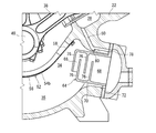
- FIG. 5 schematically shows a part of a cross section of a reciprocating compressor according to still another embodiment.
- the reciprocating compressor in FIG. 5 further includes an oil separator 64 installed in the crank chamber 34.
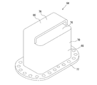
- FIG. 6 is a perspective view schematically showing the appearance of the oil separator 64. Referring to FIGS. 5 and 6, the oil separator 64 has a labyrinth portion 66 on the partition plate 54 side, and a pressure equalizing path. A cavity portion 68 is provided on the inlet end side of the.
- the maze part 66 defines a bent flow path, and the cavity 68 defines a flow path having a larger cross-sectional area than the maze part 66.
- the oil separator 64 includes a cylindrical peripheral wall 70 and a flange 72 that extends outward from one end of the peripheral wall 70.
- the axial direction of the peripheral wall 70 is directed to the crankshaft 40.
- a plurality of partition walls 76 that are orthogonal to the peripheral wall 70 are provided inside the peripheral wall 70.
- the partition walls 76 are separated from each other in the axial direction of the peripheral wall 70, and define a flow path in which the maze portion 66 is bent.
- a through hole (gas return throttle 78) communicating with the inlet end of the pressure equalizing passage 50 is provided in the flange 72.
- a through hole (oil dropping throttle 80) that communicates the midway portion of the pressure equalizing passage 50 and the crank chamber 34 is provided.
- the lubricating oil flowing down from the suction chamber 28 is returned to the crank chamber 34 through the oil drop restrictor 80.
- the cross-sectional area of the oil drop restrictor 80 is set so that the lubricating oil accumulates on the oil drop restrictor 80, and the oil droplets in the crank chamber 34 directly flow into the oil drop restrictor 80 and enter the suction chamber 28.
- a check valve that restricts the flow of fluid in the direction from the crank chamber 34 toward the suction chamber 28 may be provided at the position of the oil drop restrictor 80.
- the particle size of the oil droplet increases while passing through the labyrinth portion 66 of the oil separator 64, and the oil droplet is easily separated from the gas by gravity sedimentation while passing through the cavity portion 68. Become.
- the oil droplets are efficiently recovered by the oil separator 64, the amount of the lubricating oil flowing into the inlet end of the pressure equalizing passage 50 is further reduced, and the discharge of the lubricating oil from the reciprocating compressor is further suppressed.
- the oil separator 64 can be installed in the crank chamber 34 without causing an increase in the size of the housing 22.
- FIG. 7 schematically shows a part of a cross section of a reciprocating compressor according to still another embodiment.
- an oil return path 82 that communicates the suction chamber 28 and the crank chamber 34 is provided separately from the pressure equalizing path 50.
- the cross-sectional area of the oil return path 82 is set so that the oil return path 82 is always closed by the lubricating oil, and oil droplets in the crank chamber 34 directly flow into the oil return path 82 and reach the suction chamber 28. None do.
- FIG. 8 illustrates a configuration in which the collecting member 84 is disposed in the gap between the end portions of the partition plate 54.
- the collection member 84 has a mesh structure, and the oil droplets passing through the collection member 84 are collected and enlarged, and the enlarged oil droplets flow down to the oil storage chamber. According to the collection member 84, the amount of the lubricating oil flowing into the inlet end of the pressure equalizing passage 50 is further reduced, and the discharge of the lubricating oil from the reciprocating compressor is further suppressed.
- the refrigeration cycle described above has the oil separator 18 between the reciprocating compressor and the condenser 12, but since the lubricating oil discharged from the reciprocating compressor is reduced, the oil separator 18 may be omitted.
- the partition member 52 mentioned above was comprised by the three partition plates 54, the number of the partition plates 54 is not specifically limited.
- the partition plate 54 is made of a plate material, a slit may be formed in the plate material, or the partition plate 54 may be made of a mesh, a punching metal, or the like.
Landscapes
- Engineering & Computer Science (AREA)
- Mechanical Engineering (AREA)
- General Engineering & Computer Science (AREA)
- Compressor (AREA)
- Compressors, Vaccum Pumps And Other Relevant Systems (AREA)
Description
例えば特許文献1に記載されているように、往復動圧縮機のハウジング内には、吸入室、吐出室、シリンダ及びクランク室が区画され、クランク室の下部が潤滑油を貯留する油溜室として利用される。シリンダ内には、ピストンが往復動可能に配置され、クランク室には軸受を介して回転可能にクランク軸が配置される。ピストンはクランク軸と連接棒を介して連結され、クランク軸の回転運動がピストンの往復運動に変換される。
従って、圧縮機の通常運転(負荷運転)時には、均圧路を通じて、クランク室内の漏れガスが吸入室に返戻される。一方、特許文献1の往復動圧縮機は、アンロード機構を有しており、吸入弁を開いたままの状態での運転(無負荷運転)が可能である。負荷運転から無負荷運転への移行時には、吸入室の圧力が高くなるため、均圧路を通じて吸入室からクランク室へとガスが流れる。
なお、特許文献1の往復動圧縮機では、ハウジングの外部に設けられた均圧管が均圧路を構成しているが、均圧路は、ハウジングの内部に設けられていてもよい。
この構成では、仕切り部材が複数の仕切り板からなるので、クランク室内への仕切り部材の設置が容易である。
この構成では、仕切り板に衝突した油滴が仕切り板の下部に集まり、集まった潤滑油を貯油室に円滑に流下させることができる。
この構成では、各仕切り板の下部に集まった潤滑油を、仕切り板の端部同士の隙間を通じて、貯油室に円滑に流下させることができる。
この構成では、均圧路の開口端に流入する潤滑油の量が更に低減され、往復動圧縮機からの潤滑油の吐出が更に抑制される。
冷凍サイクルは、冷媒が循環する循環路10を有し、循環路10には、往復動圧縮機、凝縮器(高圧側熱交換器)12、膨張弁(膨張器)14及び蒸発器(低圧側熱交換器)16が冷媒の循環方向にてこの順序で配置されている。なお、本実施形態では、循環路10に、油分離器18及び受液器20が更に配置されている。
ハウジング22の内部には、吸入室28、吐出室30、シリンダ32、及び、クランク室34が設けられている。シリンダ32内にはピストン36が往復動可能に配置され、シリンダ32内には、ピストン36によって圧縮室が区画される。吸入室28は、吸入ポート24と連通するとともに、吸入弁を介して圧縮室と連通可能である。吐出室30は、吐出ポート26と連通するとともに、吐出弁を介して圧縮室と連通可能である。
そして、吸い込み容量が減少した状態が続き負荷側温度が上昇すると、蒸発器16での冷媒の蒸発が進行して吸入圧力が上昇する。
吸入圧力を下げるために吸い込み容量を増加させる場合、容量制御機構を働かせてアンローダピストン37の位置を変化させることにより、吸入弁の常時開放が解除され、吸い込み容量が増大して元に戻る。
なお、本実施形態では、潤滑油を浄化するためのオイルフィルタ46,48が貯油室35内及びハウジング22の外にそれぞれ設置されている。
往復動圧縮機においては、運転中、ピストン36とシリンダ32の壁面との隙間から冷媒が漏れ出し、クランク室34内に流入する。この漏れ出した冷媒(漏れガス)によって、クランク室34の圧力が上昇するのを抑制するために、往復動圧縮機は、クランク室34と吸入室28とを連通する均圧路50を有する。本実施形態では、ハウジング22に設けられた貫通孔によって、均圧路50が形成されている。
仕切り板54がハウジング22に固定された状態では、仕切り板54の下部56が、クランク軸40の下側に沿って下向きに凸に曲がっている。上部58は、水平方向にてクランク軸40から離れるほど高くなるように傾斜しており、クランク軸40と直交する水平方向にてクランク軸40の両側方に位置している。
図4の往復動圧縮機では、ハウジング22の外部に設けられた均圧管60によって、均圧路50が形成されている。
この構成においても、仕切り板54によって、均圧路50の入口端へ油滴が直接流入することが防止される。
図5の往復動圧縮機は、クランク室34内に設置された油分離器64を更に備えている。
図6は、油分離器64の外観を概略的に示す斜視図であり、図5及び図6を参照すると、油分離器64は、仕切り板54側に迷路部66を有し、均圧路の入口端側に空洞部68を有する。
具体的には、油分離器64は、筒形状の周壁70と、周壁70の一端から外側に向けて延びる鍔72を有する。周壁70の軸線方向はクランク軸40に向けられている。周壁70の内側には、それぞれ周壁70と直交する複数の仕切り壁76が設けられている。仕切り壁76は、周壁70の軸線方向にて相互に離隔しており、迷路部66の折れ曲がった流路を規定している。そして、鍔72には、均圧路50の入口端と連通する貫通孔(ガス戻し絞り78)が設けられている。
なお、オイル落とし絞り80の位置に、クランク室34から吸入室28に向かう方向での流体の流れを制限する逆止弁を設置してもよい。
この往復動圧縮機では、吸入室28とクランク室34とを連通する油返戻路82が、均圧路50とは別に設けられている。油返戻路82の断面積は、油返戻路82が潤滑油によって常時閉塞されるように設定されており、クランク室34内の油滴が油返戻路82に直接流入して吸入室28に到達することはない。
この捕集部材84によれば、均圧路50の入口端に流入する潤滑油の量が更に低減され、往復動圧縮機からの潤滑油の吐出が更に抑制される。
更に、上述した仕切り部材52は、3つの仕切り板54によって構成されていたが、仕切り板54の数は特に限定されることはない。また、仕切り板54は、板材によって構成されていたが、板材にはスリットが形成されていてもよく、あるいは、仕切り板54は、メッシュやパンチングメタル等によって構成されていてもよい。
28 吸入室
30 吐出室
32 シリンダ
34 クランク室
35 貯油室
36 ピストン
38 連接棒
40 クランク軸
50 均圧路
52 仕切り部材
54(54a,54b,54c) 仕切り板
56 下部
58 上部
64 油分離器
66 迷路部
68 空洞部
Claims (6)
- 吸入室、吐出室、シリンダ、及び、クランク室が設けられ、前記クランク室の下部が潤滑油を貯留するための貯油室として構成されているハウジングと、
前記シリンダ内に往復動可能に配置されたピストンと、
前記クランク室に回転可能に配置され、前記ピストンと連接棒を介して連結されたクランク軸と、
前記クランク室に開口する開口端を有し、前記吸入室と前記クランク室を連通する均圧路と、
前記クランク軸と前記均圧路の開口端との間に配置された仕切り部材とを備え、
前記仕切り部材は、前記クランク軸の一方の側方から他方の側方まで、前記クランク軸の下側を通って前記クランク軸の少なくとも下側を覆う形で広がっている
ことを特徴とする往復動圧縮機。 - 前記仕切り部材は複数の仕切り板からなり、
前記複数の板材は前記クランク軸の軸線方向に沿って配列されている
ことを特徴とする請求項1に記載の往復動圧縮機。 - 前記仕切り板は、前記クランク軸の下側に沿って湾曲した四半円筒形状の下部と、前記下部に連なって前記クランク軸の側方に位置する上部とを有する
ことを特徴とする請求項2に記載の往復動圧縮機。 - 前記クランク軸の軸線方向にて隣り合う前記複数の仕切り板の端部は、前記仕切り板の厚さ方向に隙間を存して相互に重なっている
ことを特徴とする請求項3に記載の往復動圧縮機。 - 前記仕切り板の端部の隙間に配置され、前記隙間を通過する前記潤滑油を捕集する捕集部材を更に備える
ことを特徴とする請求項4に記載の往復動圧縮機。 - 前記仕切り部材と前記均圧路の開口端との間に配置された油分離器を更に備え、
前記油分離器は、
前記仕切り部材側に設けられ、折れ曲がった流路を規定する迷路部と、
前記開口端側に設けられ、前記迷路部の流路よりも大きな断面積の流路を規定する空洞部とを有する
ことを特徴とする請求項1に記載の往復動圧縮機。
Priority Applications (9)
| Application Number | Priority Date | Filing Date | Title |
|---|---|---|---|
| PL12885949T PL2891800T3 (pl) | 2012-10-01 | 2012-10-01 | Sprężarka tłokowa |
| PCT/JP2012/075324 WO2014054092A1 (ja) | 2012-10-01 | 2012-10-01 | 往復動圧縮機 |
| HUE12885949A HUE035664T2 (en) | 2012-10-01 | 2012-10-01 | Piston compressor |
| DK12885949.3T DK2891800T3 (en) | 2012-10-01 | 2012-10-01 | PISTON COMPRESSOR |
| EP12885949.3A EP2891800B1 (en) | 2012-10-01 | 2012-10-01 | Reciprocating compressor |
| JP2014539489A JP5863135B2 (ja) | 2012-10-01 | 2012-10-01 | 往復動圧縮機 |
| US14/428,655 US20150240798A1 (en) | 2012-10-01 | 2012-10-01 | Reciprocating compressor |
| NO12885949A NO2891800T3 (ja) | 2012-10-01 | 2012-10-01 | |
| ES12885949.3T ES2652667T3 (es) | 2012-10-01 | 2012-10-01 | Compresor de movimiento alternativo |
Applications Claiming Priority (1)
| Application Number | Priority Date | Filing Date | Title |
|---|---|---|---|
| PCT/JP2012/075324 WO2014054092A1 (ja) | 2012-10-01 | 2012-10-01 | 往復動圧縮機 |
Publications (1)
| Publication Number | Publication Date |
|---|---|
| WO2014054092A1 true WO2014054092A1 (ja) | 2014-04-10 |
Family
ID=50434454
Family Applications (1)
| Application Number | Title | Priority Date | Filing Date |
|---|---|---|---|
| PCT/JP2012/075324 Ceased WO2014054092A1 (ja) | 2012-10-01 | 2012-10-01 | 往復動圧縮機 |
Country Status (9)
| Country | Link |
|---|---|
| US (1) | US20150240798A1 (ja) |
| EP (1) | EP2891800B1 (ja) |
| JP (1) | JP5863135B2 (ja) |
| DK (1) | DK2891800T3 (ja) |
| ES (1) | ES2652667T3 (ja) |
| HU (1) | HUE035664T2 (ja) |
| NO (1) | NO2891800T3 (ja) |
| PL (1) | PL2891800T3 (ja) |
| WO (1) | WO2014054092A1 (ja) |
Cited By (3)
| Publication number | Priority date | Publication date | Assignee | Title |
|---|---|---|---|---|
| WO2019130432A1 (ja) * | 2017-12-26 | 2019-07-04 | 株式会社前川製作所 | 往復動圧縮機 |
| JP2021148017A (ja) * | 2020-03-17 | 2021-09-27 | 新日本空調株式会社 | 往復動圧縮機 |
| WO2025028234A1 (ja) | 2023-07-28 | 2025-02-06 | 株式会社前川製作所 | ブローバイガスプレート及び往復動圧縮機 |
Families Citing this family (6)
| Publication number | Priority date | Publication date | Assignee | Title |
|---|---|---|---|---|
| JP2018071492A (ja) * | 2016-11-02 | 2018-05-10 | アネスト岩田株式会社 | 圧縮機 |
| CN107676250B (zh) * | 2017-10-29 | 2024-03-15 | 南京润泽流体控制设备有限公司 | 往复式注射泵 |
| US20200102943A1 (en) | 2018-10-02 | 2020-04-02 | Vilter Manufacturing Llc | 3D-Printed Oil Separation for Reciprocating Compressors |
| WO2020072083A1 (en) * | 2018-10-02 | 2020-04-09 | Vilter Manufacturing Llc | 3d-printed oil separation for reciprocating compressors |
| DE102018129473B4 (de) * | 2018-11-22 | 2025-12-11 | Bitzer Kühlmaschinenbau Gmbh | Kältemittelverdichter |
| CN109611314A (zh) * | 2018-12-29 | 2019-04-12 | 南京久鼎制冷空调设备有限公司 | 高承压亚临界co2制冷压缩机 |
Citations (4)
| Publication number | Priority date | Publication date | Assignee | Title |
|---|---|---|---|---|
| DE955987C (de) * | 1954-06-03 | 1957-01-10 | Frankfurter Maschb A G Vorm Po | Verfahren zur Entlastung des Triebwerkes bei Druckerhoehungsverdichtern |
| GB2058233A (en) * | 1979-05-10 | 1981-04-08 | Carrier Corp | Oil return system and method |
| US4887514A (en) | 1988-11-18 | 1989-12-19 | Vilter Manufacturing Corporation | Oil separation and gas pressure equalizer means for reciprocating gas compressor |
| WO2001088374A1 (en) * | 2000-05-17 | 2001-11-22 | Zexel Cold Systems Company | Reciprocating compressor |
Family Cites Families (5)
| Publication number | Priority date | Publication date | Assignee | Title |
|---|---|---|---|---|
| US2008715A (en) * | 1931-01-31 | 1935-07-23 | Gen Motors Corp | Refrigerating apparatus |
| US2844305A (en) * | 1953-11-03 | 1958-07-22 | Gen Motors Corp | Refrigerating apparatus |
| US3844688A (en) * | 1973-05-08 | 1974-10-29 | Dunham Bush Inc | Compressor crank case venting arrangement for eliminating lube oil carryover |
| US4273519A (en) * | 1978-09-05 | 1981-06-16 | Tecumseh Products Company | Split crankcase radial automotive compressor |
| JPH10196540A (ja) * | 1997-01-10 | 1998-07-31 | Toyota Autom Loom Works Ltd | 圧縮機 |
-
2012
- 2012-10-01 PL PL12885949T patent/PL2891800T3/pl unknown
- 2012-10-01 JP JP2014539489A patent/JP5863135B2/ja active Active
- 2012-10-01 EP EP12885949.3A patent/EP2891800B1/en active Active
- 2012-10-01 NO NO12885949A patent/NO2891800T3/no unknown
- 2012-10-01 US US14/428,655 patent/US20150240798A1/en not_active Abandoned
- 2012-10-01 WO PCT/JP2012/075324 patent/WO2014054092A1/ja not_active Ceased
- 2012-10-01 DK DK12885949.3T patent/DK2891800T3/en active
- 2012-10-01 HU HUE12885949A patent/HUE035664T2/en unknown
- 2012-10-01 ES ES12885949.3T patent/ES2652667T3/es active Active
Patent Citations (4)
| Publication number | Priority date | Publication date | Assignee | Title |
|---|---|---|---|---|
| DE955987C (de) * | 1954-06-03 | 1957-01-10 | Frankfurter Maschb A G Vorm Po | Verfahren zur Entlastung des Triebwerkes bei Druckerhoehungsverdichtern |
| GB2058233A (en) * | 1979-05-10 | 1981-04-08 | Carrier Corp | Oil return system and method |
| US4887514A (en) | 1988-11-18 | 1989-12-19 | Vilter Manufacturing Corporation | Oil separation and gas pressure equalizer means for reciprocating gas compressor |
| WO2001088374A1 (en) * | 2000-05-17 | 2001-11-22 | Zexel Cold Systems Company | Reciprocating compressor |
Cited By (8)
| Publication number | Priority date | Publication date | Assignee | Title |
|---|---|---|---|---|
| WO2019130432A1 (ja) * | 2017-12-26 | 2019-07-04 | 株式会社前川製作所 | 往復動圧縮機 |
| KR20200078653A (ko) | 2017-12-26 | 2020-07-01 | 가부시끼가이샤 마에가와 세이사꾸쇼 | 왕복식 압축기 |
| CN111373147A (zh) * | 2017-12-26 | 2020-07-03 | 株式会社前川制作所 | 往复运动式压缩机 |
| CN111373147B (zh) * | 2017-12-26 | 2022-02-11 | 株式会社前川制作所 | 往复运动式压缩机 |
| JP2021148017A (ja) * | 2020-03-17 | 2021-09-27 | 新日本空調株式会社 | 往復動圧縮機 |
| WO2025028234A1 (ja) | 2023-07-28 | 2025-02-06 | 株式会社前川製作所 | ブローバイガスプレート及び往復動圧縮機 |
| KR20260019638A (ko) | 2023-07-28 | 2026-02-10 | 가부시끼가이샤 마에가와 세이사꾸쇼 | 블로바이 가스 플레이트 및 왕복동 압축기 |
| EP4722534A4 (en) * | 2023-07-28 | 2026-04-15 | Maekawa Seisakusho Kk | GAS LEAK PLATE AND ALTERNATIVE COMPRESSOR |
Also Published As
| Publication number | Publication date |
|---|---|
| JPWO2014054092A1 (ja) | 2016-08-25 |
| JP5863135B2 (ja) | 2016-02-16 |
| PL2891800T3 (pl) | 2018-03-30 |
| EP2891800A1 (en) | 2015-07-08 |
| EP2891800A4 (en) | 2016-09-07 |
| ES2652667T3 (es) | 2018-02-05 |
| US20150240798A1 (en) | 2015-08-27 |
| NO2891800T3 (ja) | 2018-04-21 |
| DK2891800T3 (en) | 2018-01-02 |
| EP2891800B1 (en) | 2017-11-22 |
| HUE035664T2 (en) | 2018-05-28 |
Similar Documents
| Publication | Publication Date | Title |
|---|---|---|
| JP5863135B2 (ja) | 往復動圧縮機 | |
| US6237362B1 (en) | Internal oil separator for compressors of refrigeration systems | |
| US9011109B2 (en) | Variable Capacity Compressor | |
| JP6898468B2 (ja) | 往復動圧縮機 | |
| US12339043B2 (en) | Compressor | |
| JP2009063234A (ja) | 圧縮機潤滑システム | |
| US20130272903A1 (en) | Refrigerant Compressor | |
| CN102312816A (zh) | 密闭型压缩机及制冷循环装置 | |
| JP6540954B2 (ja) | 圧縮機 | |
| TWI903638B (zh) | 漏氣板及往復式壓縮機 | |
| JP2009108750A (ja) | ピストン型圧縮機 | |
| JP2013170556A (ja) | 密閉形圧縮機及びこれを用いた冷蔵庫 | |
| CN102725527A (zh) | 流体机械 | |
| JP2010275870A (ja) | 密閉型圧縮機および冷凍冷蔵装置 | |
| JP2003293953A (ja) | レシプロ式密閉型電動圧縮機 | |
| CN107975476A (zh) | 低背压压缩机 | |
| JP4946988B2 (ja) | 圧縮機 | |
| JP5463275B2 (ja) | 密閉型圧縮機及びこれを備えた冷蔵庫 | |
| JP2013245666A (ja) | 密閉型圧縮機及びこれを備えた冷蔵庫 | |
| JP2009264110A (ja) | 圧縮機 | |
| JP2005002823A (ja) | 圧縮機 | |
| JP2007077929A (ja) | 圧縮機 | |
| JP2008008271A (ja) | 圧縮機 | |
| JP2011012600A (ja) | スクロール圧縮機 | |
| JP2005002822A (ja) | 圧縮機 |
Legal Events
| Date | Code | Title | Description |
|---|---|---|---|
| 121 | Ep: the epo has been informed by wipo that ep was designated in this application |
Ref document number: 12885949 Country of ref document: EP Kind code of ref document: A1 |
|
| ENP | Entry into the national phase |
Ref document number: 2014539489 Country of ref document: JP Kind code of ref document: A |
|
| WWE | Wipo information: entry into national phase |
Ref document number: 14428655 Country of ref document: US |
|
| NENP | Non-entry into the national phase |
Ref country code: DE |
|
| REEP | Request for entry into the european phase |
Ref document number: 2012885949 Country of ref document: EP |
|
| WWE | Wipo information: entry into national phase |
Ref document number: 2012885949 Country of ref document: EP |