WO2014050939A1 - 発電機におけるステータ構造 - Google Patents
発電機におけるステータ構造 Download PDFInfo
- Publication number
- WO2014050939A1 WO2014050939A1 PCT/JP2013/076000 JP2013076000W WO2014050939A1 WO 2014050939 A1 WO2014050939 A1 WO 2014050939A1 JP 2013076000 W JP2013076000 W JP 2013076000W WO 2014050939 A1 WO2014050939 A1 WO 2014050939A1
- Authority
- WO
- WIPO (PCT)
- Prior art keywords
- stator core
- coil end
- coil
- slots
- stator
- Prior art date
Links
Images


Classifications
-
- H—ELECTRICITY
- H02—GENERATION; CONVERSION OR DISTRIBUTION OF ELECTRIC POWER
- H02K—DYNAMO-ELECTRIC MACHINES
- H02K1/00—Details of the magnetic circuit
- H02K1/06—Details of the magnetic circuit characterised by the shape, form or construction
- H02K1/12—Stationary parts of the magnetic circuit
- H02K1/18—Means for mounting or fastening magnetic stationary parts on to, or to, the stator structures
- H02K1/185—Means for mounting or fastening magnetic stationary parts on to, or to, the stator structures to outer stators
-
- H—ELECTRICITY
- H02—GENERATION; CONVERSION OR DISTRIBUTION OF ELECTRIC POWER
- H02K—DYNAMO-ELECTRIC MACHINES
- H02K3/00—Details of windings
- H02K3/46—Fastening of windings on the stator or rotor structure
- H02K3/50—Fastening of winding heads, equalising connectors, or connections thereto
-
- H—ELECTRICITY
- H02—GENERATION; CONVERSION OR DISTRIBUTION OF ELECTRIC POWER
- H02K—DYNAMO-ELECTRIC MACHINES
- H02K3/00—Details of windings
- H02K3/46—Fastening of windings on the stator or rotor structure
- H02K3/52—Fastening salient pole windings or connections thereto
- H02K3/527—Fastening salient pole windings or connections thereto applicable to rotors only
-
- H—ELECTRICITY
- H02—GENERATION; CONVERSION OR DISTRIBUTION OF ELECTRIC POWER
- H02K—DYNAMO-ELECTRIC MACHINES
- H02K5/00—Casings; Enclosures; Supports
- H02K5/04—Casings or enclosures characterised by the shape, form or construction thereof
- H02K5/16—Means for supporting bearings, e.g. insulating supports or means for fitting bearings in the bearing-shields
- H02K5/161—Means for supporting bearings, e.g. insulating supports or means for fitting bearings in the bearing-shields radially supporting the rotary shaft at both ends of the rotor
-
- H—ELECTRICITY
- H02—GENERATION; CONVERSION OR DISTRIBUTION OF ELECTRIC POWER
- H02K—DYNAMO-ELECTRIC MACHINES
- H02K5/00—Casings; Enclosures; Supports
- H02K5/24—Casings; Enclosures; Supports specially adapted for suppression or reduction of noise or vibrations
-
- H—ELECTRICITY
- H02—GENERATION; CONVERSION OR DISTRIBUTION OF ELECTRIC POWER
- H02K—DYNAMO-ELECTRIC MACHINES
- H02K9/00—Arrangements for cooling or ventilating
- H02K9/14—Arrangements for cooling or ventilating wherein gaseous cooling medium circulates between the machine casing and a surrounding mantle
Definitions
- a plurality of slots are provided on the inner periphery of a stator core surrounding a rotor fixed to a rotating shaft, and a plurality of slots are accommodated in slots spaced apart in the circumferential direction of the stator core with a plurality of slots interposed therebetween.
- a coil comprising a plurality of coil end portions arranged on the outer sides in the axial direction of the stator core is wound around the stator core, and a cooling fan for circulating cooling air through the stator core is rotated.
- the present invention relates to a generator fixed to a shaft, and more particularly to improvement of a stator structure.
- a generator stator in which a plurality of coil end portions are arranged in an annular arrangement having an inner diameter larger than the inner diameter of the starter core and arranged at both ends of the stator core is already known from Patent Document 1 and the like. Yes.
- Patent Document 1 in the structure in which a plurality of coil end portions are arranged at both ends of the stator core so as to have an annular arrangement having an inner diameter larger than the inner diameter of the starter core, the length of the coil end portion is long. Not only does the copper length increase, but the area of the coil end that comes into contact with the outside air becomes relatively small, making it difficult to dissipate heat from the coil end.
- the present invention has been made in view of such circumstances, and the length of the coil end portion is shortened to reduce the amount of copper, and the cooling effect can be improved by increasing the heat radiation area of the coil end portion.
- An object is to provide a stator structure in a generator.
- a plurality of slots are provided on the inner periphery of a stator core that surrounds a rotor fixed to a rotating shaft, and a plurality of slots are interposed between each other in the circumferential direction of the stator core.
- a coil in which a plurality of coil side portions accommodated in spaced apart slots are connected by a plurality of coil end portions arranged outside the both axial ends of the stator core is wound around the stator core, and cooling air is contained in the stator core.
- the one end side along the axial direction of the stator core is 2 inward from the inner periphery of the stator core as viewed from the direction along the axis of the rotating shaft.
- a plurality of coil end portions that connect the two slots by shortcuts are dispersed so that an opening that allows the rotation shaft to pass therethrough is formed in the central portion.
- the first feature to be location.
- the present invention provides a support member having a plurality of fitting recesses, the coil end portions being connected to the fitting recesses in order to maintain a distributed arrangement of the plurality of coil end portions.
- the second feature is that each of the coil end portions is attached so as to be fitted to each other.
- a plurality of coil end portions form a shortcut between the two slots while forming an opening that allows the rotation shaft to pass therethrough. Therefore, the length of the coil end portion can be shortened to reduce the amount of copper, and the cooling effect by the cooling air flowing through the stator core can be improved. Since the coil end portions are dispersedly arranged, the heat dissipation area of the coil end portions can be increased and a more excellent cooling effect can be obtained.
- the plurality of coil end portions are fitted into the plurality of fitting recesses of the support member to maintain the distributed arrangement state of each coil end portion, the number of parts is increased.
- the distributed arrangement of the plurality of coil end portions can be easily maintained while suppressing the above.
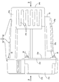
- FIG. 1 is a side view of the generator according to the first embodiment.
- FIG. 2 is a view taken in the direction of arrow 2 in FIG.
- FIG. 3 is a view taken in the direction of arrow 3 in FIG.
- First embodiment 4 is a cross-sectional view taken along line 4-4 of FIG.
- First embodiment 5 is a cross-sectional view taken along line 5-5 of FIG.
- First embodiment 6 is a perspective view of the first bracket.
- FIG. 7 is a perspective view of the second bracket.
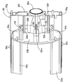
- FIG. 8 is a perspective view of the rotor and the cooling fan.
- (First embodiment) 9 is a cross-sectional view taken along line 9-9 of FIG. (First embodiment) FIG.
- FIG. 10 is a perspective view of the bobbin half.
- (First embodiment) 11 is a cross-sectional view of the rotor taken along line 11-11 in FIG.
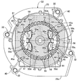
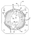
- FIG. 12 is a perspective view of the stator.
- FIG. 13 is a front view of one end of the stator as viewed from the direction along the axis of the rotating shaft.
- FIG. 14 is a view corresponding to FIG. 3 in a state in which a vibration-proof rubber is attached to the attachment portion.
- FIG. 15 is a view corresponding to FIG. 3 in a state in which a mounting leg is mounted on the mounting portion.
- FIG. 16 is a view corresponding to FIG.
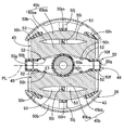
- FIG. 17 is a perspective view of a stator corresponding to FIG. 12 of the second embodiment.
- FIGS. 1 to 16 The first embodiment of the present invention will be described with reference to FIGS. 1 to 16.
- the housing 21 of the generator is coupled to the first bracket 22 and the first bracket 22.
- a cover 24 attached to the first bracket 22 on the opposite side of the second bracket 23.
- a stator 25 is fixed to the first bracket 22 of the housing 21, and one end portion of the rotating shaft 27 is connected to the ball bearing 28 on the bearing portion 22 a of the first bracket 22.
- a rotor 26 that is rotatably supported through the stator 25 and is surrounded by the stator 25 is fixed to the rotary shaft 27, and a cooling fan 29 that rotates together with the rotary shaft 27 is covered with the second bracket 23.
- the first bracket 22 has a substantially cylindrical shape surrounding the bearing portion 22 a formed in a short cylindrical shape so as to fit the outer ring 28 a of the ball bearing 28 and the stator 25.
- the cylindrical portion 22b and one end of the cylindrical portion 22b are spaced apart in the circumferential direction of the bearing portion 22a, for example, four locations, and the other end is spaced in the circumferential direction of the one end portion of the cylindrical portion 22b.
- a retaining ring 30 for preventing axial movement of the ball bearing 28 in the bearing portion 22a is interposed.
- the second bracket 23 has a cylindrical side wall portion 23a whose one end is coupled to the cylindrical portion 22b of the first bracket 22, and a radius from the other end of the side wall portion 23a.
- An inward flange 23b projecting inward in the direction is integrally formed, and a circular opening 31 is formed on the inner periphery of the inward flange 23b.
- a flat outward flange 22d is integrally provided so as to protrude outward, and on the outer periphery of the outward flange 22d.
- a coupling protrusion 22e that slightly protrudes toward the second bracket 23 so as to abut one end of the side wall 23a is formed in one piece.
- the coupling protrusion 22e of the first bracket 22 is bolts 32, 32... Arranged at a plurality of locations spaced in the circumferential direction of the cylindrical portion 22b, and the side wall portion 23a of the second bracket 23.
- the second bracket 23 is attached to a drive source having a crankshaft 34 as a drive shaft connected coaxially to the rotary shaft 27, for example, an engine body 35 of the internal combustion engine E.
- the flange 23b is provided with a plurality of, for example, four fastening holes 36, 36,... Disposed around the opening 31, and the second bracket 23 has bolts 37, which are inserted into the fastening holes 36, 36,. 37... Are fastened to the engine body 35 at 37.
- the rotary shaft 27 has a tapered hole 38 at the end on the internal combustion engine E side, and is formed in a cylindrical shape.
- the rotary shaft 27 is inserted into the second bracket 23 through the opening 31.
- a tapered portion 34a at the end of the crankshaft 34 is fitted coaxially into the tapered hole 38, and a bolt 39 inserted into the rotating shaft 27 from the cover 24 side is screwed into the crankshaft 34 and tightened.
- the rotary shaft 27 is coaxially connected to the crankshaft 34 so as not to be relatively rotatable.
- the first bracket 22 is fastened to the engine body 35 in a state where the rotor 25 is fixed to a rotating shaft 27 to which the stator 25 is fixed and one end portion is rotatably supported by the bearing portion 22a.
- the two end portions of a plurality of, for example, two knock pins 40 for positioning the rotary shaft 27 and the crankshaft 34 to be aligned with each other. are provided in the coupling protrusion 22e of the first bracket 22 and the side wall 23a of the second bracket 23, respectively.
- the rotor 26 is formed by laminating a plurality of electromagnetic steel plates, and on a rotor core 43 fixed to the rotary shaft 27, a plane passing through the central axis of the rotary shaft 27.
- Field coils 45, 45 arranged on both sides of the PL are wound around a bobbin 44.
- One end of the rotating shaft 27 is press-fitted into an inner ring 28b of the ball bearing 28, and a pair of fields is provided on the outer periphery of a slip ring support 46 fixed to the rotating shaft 27 between the ball bearing 28 and the rotor 26.
- a pair of slip rings 47, 47 electrically connected to the magnetic coils 45, 45 are provided at intervals in the axial direction of the rotary shaft 27 and are supported by the first bracket 22 as shown in FIG. 4.
- a pair of brushes 49, 49 held by the brush holder 48 are in sliding contact with the slip rings 47, 47 individually.
- the bobbin 44 is attached to the rotor core 43 such that a pair of bobbin halves 50 and 50 formed in the same shape by a synthetic resin sandwich the rotor core 43 from both sides in a direction along the axis of the rotating shaft 27. Become.
- the bobbin half 50 includes a cylindrical support portion 50 a through which the rotation shaft 27 is inserted outside the rotor core 43 along the axis of the rotation shaft 27, and the rotation shaft 27.
- a pair of ends that are connected to both sides of the inner end of the cylindrical support portion 50a so as to extend along the one plane PL passing through the central axis, and that are opposed to and contact the outer end of the rotor core 43 along the axis of the rotary shaft 27.
- the plate portions 50b, 50b, and two ends of the end plate portions 50b are connected to the longitudinal ends on the one plane PL side.
- the inner side plate portions 50c, 50c,..., The outer side plate portions 50d, 50d, ... facing the inner side plate portions 50c, 50c, ..., and the inner side plate portions 50c, 50c, ... and the inner side plate portions 50d, 50d, ... are connected. Opening grooves 51, 51 ... are formed respectively by the bottom plate portions 50e, 50e ..., and two pairs of grooves 51, 51 ... which make a pair in the direction along the one plane PL are the bobbin half 50, that is, the bobbin. 44. Further, the inner regulating plate portions 50f, 50f are provided with flow holes 52, 52... Located on both sides of the cylindrical support portion 50a, and the flow holes 52, 52 are in a direction along the axis of the rotary shaft 27. Are formed integrally with the bobbin half 50.
- coil sides 45 a and 45 a of the field coil 45 are accommodated in the grooves 51 and 51 that form a pair in the direction along the one plane PL passing through the central axis of the rotating shaft 27.
- the coil end portions 45b and 45b at both ends of the field coil 45 are restricted from moving toward the one plane PL by the inner regulating plate portion 50f so as to connect the paired coil side portions 45a and 45a. It arrange
- the coil ends 45b and 45b of the field coil 45 are formed on the bobbin 44 at the portion corresponding to the outer end of the rotor core 43, as shown in FIG.
- Separating projections 50i, 50i are provided to divide the outer side portion 45ba ... and the outer side portion 45bb ..., and the inner projections are formed on both sides of the separating projections 50i, 50i along the circumferential direction of the rotary shaft 27.
- Gaps 53 are formed between the side portions 45ba and the outer side portions 45bb, respectively.
- the end plate portion 50b of the bobbin 44 has support bases 50j and 50j that protrude from the central portion in the longitudinal direction outward in the axial direction of the rotary shaft 27 and support the coil end portions 45b and 45b.
- the air passages 54 and 54 are formed between the coil end portions 45b and the end plate portions 50b on both sides of the support bases 50j and 50j along the circumferential direction of the rotary shaft 27, and are integrated with the end plate portion 50b.
- the separation protrusions 50i are projected from the support base 50j.
- air passages 54, 54 formed between the coil end portion 45 b and the end plate portion 50 b on both sides of the support base 50 j are formed at the outer ends along the radial direction of the rotating shaft 27 and the support base 50 j and
- the inner ends of the air passages 54, 54 that open to the outside of the rotor 26 through the space between the outer restricting protrusions 50 k, 50 k and extend along the radial direction of the rotating shaft 27 are provided in the inner restricting plate portion 50 f. It is opened to the outside of the rotor 26 at the outer end along the axial direction of the rotary shaft 27 through the flow holes 52.
- the stator 25 includes a plurality of output coils 57, 57... And a pair of stator coils 56, which are formed by laminating a plurality of electromagnetic steel plates and provided with a plurality of slots 55.
- the exciting coils 58 and 58 are wound.
- stator 25 is fixed to the first bracket 22 so as to be surrounded by the cylindrical portion 22b of the first bracket 22, and the cooling air sucked by the cooling fan 29 is the rotor 26.
- the stator 25 can be circulated between the outer periphery of the stator 25 and the inner periphery of the cylindrical portion 22b.
- a plurality of circumferential locations, for example, four locations on the outer periphery of the stator core 56 are press-fitted into the cylindrical portion 22b.
- the inner periphery of the cylindrical portion 22b is tapered with the second bracket 23 side as the maximum diameter in order to facilitate the insertion of the stator core 56 into the cylindrical portion 22b from the second bracket 23 side.
- the press-fit portions 59 for press-fitting the outer periphery of the stator core 56 are provided at four locations spaced in the circumferential direction of the intermediate portion of the cylindrical portion 22b.
- the press-fit portions 59 have the press-fit surfaces 60 extending along the axis of the rotary shaft 27 at the tip and extend in parallel to the direction along the axis of the rotary shaft 27. It is composed of two or three ridges 61, 61 ... projecting integrally on the inner surface of 22b, and between each of the ridges 61, 61 ... between the outer circumference of the stator 25 and the inner circumference of the cylindrical portion 22b.
- the cooling air can be circulated.
- the plurality of output coils 57, 57... And the pair of exciting coils 58, 58 are separated from each other in the circumferential direction of the stator core 56 with a plurality of slots 55, 55.
- a plurality of coil side portions 57a, 57a,... 58a, 58a,... Accommodated in 55, 55 are arranged outside the both axial ends of the stator core 56.
- stator core 56 is located on the inner side of the inner periphery of the stator core 56 when viewed from the direction along the axis of the rotary shaft 27.
- the fastener 63 an electrically insulated adhesive tape or lacing yarn may be used.
- the cooling fan 29 includes a cylindrical mounting tube portion 29 a that is fitted and fixed to the rotating shaft 27 in the second bracket 23, and the rotor 26.
- a taper tube portion 29b having a small diameter end connected to the mounting tube portion 29a so as to increase in diameter in the opposite direction, and a base end at a circumferentially spaced position on the outer periphery of the taper tube portion 29b Are formed in a ring shape so as to face the cooling fan 29 side end of the stator 25 and on the outer periphery of the plurality of blades 29c, 29c.
- a ring plate-like partition plate 29d provided in common is integrally provided, and a plurality of reinforcing ribs 29e, 29e,... Are integrally protruded from the inner periphery of the tapered cylindrical portion 29b.
- a discharge cylinder part 23c for discharging the cooling air discharged from the cooling fan 29 to the side is integrally provided at the lower part of the second bracket 23, and an outer end opening of the discharge cylinder part 23c is provided. Is provided with a louver 64 that divides the outer end opening into a plurality of sections.
- the cover 24 has a cylindrical side wall portion 24a and an end wall portion 24b that closes the outer end of the side wall portion 24a.
- the first bracket 22 is formed in a cylindrical shape and is fastened with bolts 65 and 65 to cylindrical boss portions 22f and 22f provided integrally on both sides of the bearing portion 22a in the first bracket 22. Fixed to.
- a plurality of first suction holes 66, 66... Opened downward are provided in the lower part of the side wall 24 a of the cover 24.
- a plurality of second suction holes 67 extending in the direction along the axis of the rotary shaft 27 are provided on both sides of the side wall portion 23a with a space therebetween in the vertical direction.
- 67... Are concealed in a side view, and flanges 24 c, 24 c... Projecting from the upper edges of the second suction holes 67, 67.
- the end wall portion 24b of the cover 24 is provided with a plurality of third suction holes 68, 68... By the operation of the cooling fan 29, and the first suction holes 66, 66. The cooling air is sucked into the housing 21 through the third suction holes 68, 68.
- one end portion of the first bracket 22, that is, the lower portion of the end portion on the cover 24 side, is a flat surface facing the cover 24 side so as to be disposed below the cover 24 when viewed from the cover 24 side.
- a pair of left and right mounting portions 22g, 22g having mounting surfaces 70, 70 are integrally provided.
- the mounting portions 22g and 22g are provided with a pair of vibration isolating rubbers 72, 72 for bolts 71, 72 for supporting the generator on the mount 69 via the vibration isolating rubbers 72, 72, for example.
- the mounting legs 73 are attached with a pair of bolts 71 and 71, and as shown in FIG.
- the state in which the stay 74 for mounting the exhaust muffler and the anti-vibration rubbers 72, 72 can be switched together by a pair of bolts 71, 71 can be switched, and the support legs of the generator can be made versatile. Can do.
- the first bracket 22 having a bearing portion 22a that pivotally supports one end of the rotating shaft 27, and the second bracket that covers the cooling fan 29 that rotates together with the rotating shaft 27.
- the stator 25 is fixed to a housing 21 having a stator 23, and the rotor 26 surrounded by the stator 25 is fixed to the rotating shaft 27.
- the stator 25 is fixed to the first bracket 22, and the A cylindrical portion 22b surrounding the stator 25 is integrally provided so that the cooling air sucked by the cooling fan 29 is circulated between the outer periphery of the stator 25, and the second bracket 23 is connected to the cylindrical portion. 22b, the cooling air is circulated along the outer periphery of the stator 25 to increase the cooling efficiency of the stator 25, and the long through-bolt
- the so as to couple the first and second brackets 22 and 23 without using the cost can be reduced.
- stator 25 since a plurality of circumferential positions on the outer periphery of the stator 25 are press-fitted into the cylindrical portion 22b, the number of parts can be reduced when the stator 25 is fixed to the first bracket 22.
- the cooling fan 29 is provided with a ring-plate-shaped partition plate 29d facing the end of the stator 25 on the cooling fan 29 side, the circulation of the cooling air that has circulated along the outer periphery of the stator 25 By changing the direction to the rotating shaft 27 side at the end of the stator 25 on the cooling fan 29 side, the end of the stator 25 on the cooling fan 29 side can be effectively cooled with cooling air.
- the second bracket 23 fastened to the engine body 35 of the internal combustion engine E including the crankshaft 34 coaxially connected to the rotary shaft 27 and one end portion of the rotary shaft 27 are rotated by the bearing portion 22a of the first bracket 22.
- both ends of a plurality of knock pins 40 for positioning the shafts of the rotary shaft 27 and the crankshaft 34 together are fitted. Since the positioning holes 41..., 42... Are provided in the first and second brackets 22 and 23, respectively, the concave and convex fitting portions are not required as compared with the case where the first and second brackets 22 and 23 are fitted and positioned. Further, it is possible to further increase the cooling effect by increasing the outer diameter of the cooling fan 29 without increasing the outer shape of the second bracket 23.
- the rotor 26 has field coils 45, 45 arranged on both sides of a plane PL passing through the central axis of the rotary shaft 27 on a bobbin 44 attached to the rotor core 43 fixed to the rotary shaft 27.
- the bobbin 44 is configured to be wound and corresponds to the outer end of the rotor core 43 in the axial direction.
- the coil end portions 45b at both ends of the field coils 45 along the axial direction of the rotary shaft 27 are provided on the bobbin 44.
- 45b are separated into an inner portion 45ba along the radial direction of the rotary shaft 27 and an outer portion 45bb..., 45b, along the circumferential direction of the rotary shaft 27.
- gaps 53 are formed between the inner side portions 45ba and the outer side portions 45b on both sides of the separation protrusions 50i, respectively, the heat dissipation area of the coil end portion 45b of the field coil 45 is formed. Increases, the coil end portions 45b and thus the field coil 45 effectively cooled, thereby improving the power generation efficiency.
- the field plate is raised from the end plate portions 50b of the bobbin 44 so as to face and abut the outer end of the rotor core 43 in the axial direction of the rotary shaft 27 from the end plate portions 50b.
- a support base 50j for supporting the coil end portion 45b of the coil 45 is provided between the coil end portion 45b and the end plate portion 50b on both sides of the support base 50j along the circumferential direction of the rotary shaft 27.
- the separation protrusion 50i is provided on the support base 50j. Therefore, the heat dissipation area of the coil end portion 45b is further increased, and the coil end portion 45b is formed. As a result, the field coil 45 can be cooled more effectively, and the power generation efficiency can be further improved.
- a plurality of slots 55, 55... are provided on the inner periphery of the stator core 56 surrounding the rotor 26 fixed to the rotary shaft 27, and the plurality of slots 55, 55.
- a plurality of coil side portions 57a, 57a,... 58a, 58a,... Housed in slots 55, 55 spaced apart from each other are arranged on the outer sides in the axial direction of the stator core 56.
- a pair of exciting coils 58, 58 connected by 58 b, 58 b are wound around the stator core 56, and at one end side along the axial direction of the stator core 56, the rotating shaft A plurality of coils that connect the two slots in a shortcut manner inwardly of the inner periphery of the stator core 56 as viewed from the direction along the axis 27
- the end portions 57b, 57b,... 58b, 58b are dispersedly arranged so as to form an opening 62 allowing the insertion of the rotating shaft 27 at the center, so that the coil end portions 57b, 57b,.
- the amount of copper can be reduced by reducing the length of the coil, and the cooling effect by the cooling air flowing through the stator core 56 can be improved, and the heat dissipation of the coil end portions 57b, 57b,.
- the area can be increased and a more excellent cooling effect can be obtained.
- FIG. 17 A second embodiment of the present invention will be described with reference to FIG. 17.
- a plurality of coil end portions 57 b, 57 b, 58 b, 58 b are connected to the rotary shaft 27 ( (See the first embodiment), the two slots 55, 55 are arranged so as to be short-cut and connected to the inside of the stator core 56 as seen from the direction along the axis. .. Are attached to the coil end portions 57b, 57b... 58b, 58b.
- the coil end portions 57b, 57b,..., 58b, 58b are fitted into the fitting recesses 81, 81... Of the binding member 80, so that the opening 62 is formed at the center.
- the end portions 57b, 57b ..., 58b, 58b are maintained in a distributed state, and the coil end portions 57b, 57b ...; 58b, 58b are impregnated with varnish while the binding members 80 are attached. Fixed to each other.
- the distributed arrangement of the plurality of coil end portions 57b, 57b,..., 58b, 58b can be easily maintained while suppressing an increase in the number of parts.
Landscapes
- Engineering & Computer Science (AREA)
- Power Engineering (AREA)
- Windings For Motors And Generators (AREA)
- Synchronous Machinery (AREA)
- Motor Or Generator Cooling System (AREA)
Abstract
回転軸に固定されるロータを囲繞するステータコアの内周に複数のスロットが設けられ、相互間に複数のスロットを介在させてステータコアの周方向に離隔したスロットに収容される複数のコイル辺部がステータコアの軸方向両端外方に配置される複数のコイルエンド部で連結されて成るコイルがステータコアに巻装され、ステータコア内に冷却空気を流通させる冷却ファンが回転軸に固定される発電機において、ステータコア(56)の軸方向に沿う一端側で、回転軸の軸線に沿う方向から見てステータコア(56)の内周よりも内方で2つのスロット(55)間をショートカットして結ぶ複数のコイルエンド部(57b,58b)が、回転軸の挿通を許容する開口部(62)を中心部に形成するようにして分散配置される。これにより、コイルエンド部の長さを短くして銅量の低減を図るとともにコイルエンド部の放熱面積増加によって冷却効果の向上を図ることができる。
Description
本発明は、回転軸に固定されるロータを囲繞するステータコアの内周に複数のスロットが設けられ、相互間に複数のスロットを介在させて前記ステータコアの周方向に離隔したスロットに収容される複数のコイル辺部が前記ステータコアの軸方向両端外方に配置される複数のコイルエンド部で連結されて成るコイルが前記ステータコアに巻装され、前記ステータコア内に冷却空気を流通させる冷却ファンが前記回転軸に固定される発電機に関し、特にステータ構造の改良に関する。
発電機のステータにおいて、複数のコイルエンド部をスタータコアの内径よりも大きな内径の環状配置となるように纏めてステータコアの両端に配置するようにしたものが、特許文献1等で既に知られている。
ところが、上記特許文献1で開示されるように、スタータコアの内径よりも大きな内径の環状配置となるように複数のコイルエンド部を纏めてステータコアの両端に配置する構造では、コイルエンド部の長さが長くなって銅量が増えるだけでなく、コイルエンド部の外気に触れる面積が比較的小さくなり、コイルエンド部から放熱し難い。
本発明は、かかる事情に鑑みてなされたものであり、コイルエンド部の長さを短くして銅量の低減を図るとともにコイルエンド部の放熱面積増加によって冷却効果の向上を図り得るようにした発電機におけるステータ構造を提供することを目的とする。
上記目的を達成するために、本発明は、回転軸に固定されるロータを囲繞するステータコアの内周に複数のスロットが設けられ、相互間に複数のスロットを介在させて前記ステータコアの周方向に離隔したスロットに収容される複数のコイル辺部が前記ステータコアの軸方向両端外方に配置される複数のコイルエンド部で連結されて成るコイルが前記ステータコアに巻装され、前記ステータコア内に冷却空気を流通させる冷却ファンが前記回転軸に固定される発電機において、前記ステータコアの軸方向に沿う一端側で、前記回転軸の軸線に沿う方向から見て前記ステータコアの内周よりも内方で2つのスロット間をショートカットして結ぶ複数のコイルエンド部が、前記回転軸の挿通を許容する開口部を中心部に形成するようにして分散配置されることを第1の特徴とする。
また本発明は、第1の特徴の構成に加えて、複数の嵌合凹部を有する支持部材が、複数の前記コイルエンド部の分散配置を維持すべく、それらのコイルエンド部を前記嵌合凹部にそれぞれ嵌合させるようにして複数の前記コイルエンド部に装着されることを第2の特徴とする。
本発明の第1の特徴によれば、ステータコアの軸方向に沿う一端側で、複数のコイルエンド部が、回転軸の挿通を許容する開口部を中心部で形成しながら2つのスロット間をショートカットして結ぶように配置されるので、コイルエンド部の長さを短くして銅量の低減を図ることができるとともに、ステータコア内を流通する冷却空気による冷却効果を向上することができ、しかも複数のコイルエンド部は分散配置されるので、コイルエンド部の放熱面積を増大し、より優れた冷却効果を得ることができる。
また本発明の第2の特徴によれば、支持部材が有する複数の嵌合凹部に、複数のコイルエンド部を嵌合させで各コイルエンド部の分散配置状態を維持するので、部品点数の増大を抑えつつ複数のコイルエンド部の分散配置を簡単に維持することができる。
26・・・ロータ
27・・・回転軸
55・・・スロット
56・・・ステータコア
57,58・・・コイル
57a,58a・・・コイル辺部
57b,58b・・・コイルエンド部
62・・・開口部
80・・・結束部材
81・・・嵌合凹部
27・・・回転軸
55・・・スロット
56・・・ステータコア
57,58・・・コイル
57a,58a・・・コイル辺部
57b,58b・・・コイルエンド部
62・・・開口部
80・・・結束部材
81・・・嵌合凹部
以下、本発明の実施の形態について添付の図面を参照しながら説明する。
本発明の第1の実施の形態について図1~図16を参照しながら説明すると、先ず図1~図3において、この発電機のハウジング21は、第1ブラケット22と、第1ブラケット22に結合される第2ブラケット23と、第2ブラケット23と反対側で第1ブラケット22に取付けられるカバー24とを備える。
図4および図5を併せて参照して、前記ハウジング21の第1ブラケット22にはステータ25が固定されており、第1ブラケット22が有する軸受部22aに回転軸27の一端部がボールベアリング28を介して回転自在に支承され、前記ステータ25で囲まれるロータ26が前記回転軸27に固定され、前記回転軸27とともに回転する冷却ファン29が第2ブラケット23で覆われる。
図6を併せて参照して、第1ブラケット22は、前記ボールベアリング28の外輪28aを嵌入させるようにして短円筒状に形成される前記軸受部22aと、前記ステータ25を囲繞する略円筒状の筒状部22bと、前記軸受部22aの周方向に間隔をあけた複数箇所たとえば4箇所に一端部が連なるとともに他端部が前記筒状部22bの一端部の周方向に間隔をあけた複数箇所に連なる複数の連結腕部22c,22c…とを一体に有する。
前記軸受部22aに嵌入された前記外輪28aの外周および前記軸受部22aの内周間には、前記ボールベアリング28の前記軸受部22a内での軸方向移動を阻止する止め輪30が介装される。
図7を併せて参照して、第2ブラケット23は、第1ブラケット22の前記筒状部22bに一端部が結合される筒状の側壁部23aと、該側壁部23aの他端部から半径方向内方に張り出す内向き鍔部23bとを一体に有し、前記内向き鍔部23bの内周で円形の開口部31が形成される。
第1ブラケット22における筒状部22bの第2ブラケット23側の端部には、平坦な外向き鍔部22dが外側方に張り出すように一体に設けられ、その外向き鍔部22dの外周には、第2ブラケット23における前記側壁部23aの一端部を当接させるようにして第2ブラケット23側にわずかに突出する結合突部22eが無状に連なって一体に形成される。而して第1ブラケット22の前記結合突部22eは、前記筒状部22bの周方向に間隔をあけた複数箇所に配置されるボルト32,32…で、第2ブラケット23の前記側壁部23aに締結される。
第2ブラケット23は、前記回転軸27に同軸に連結される駆動軸としてのクランクシャフト34を備える駆動源たとえば内燃機関Eの機関本体35に取付けられるものであり、第2ブラケット23の前記内向き鍔部23bには、前記開口部31の周囲に配置される複数たとえば4つの締結孔36,36…が設けられ、第2ブラケット23は、前記締結孔36,36…に挿通されるボルト37,37…で前記機関本体35に締結される。
前記回転軸27は、前記内燃機関E側の端部にテーパ孔38を有して円筒状に形成されるものであり、前記開口部31を貫通して第2ブラケット23内に挿入される前記クランクシャフト34の端部のテーパ部34aが前記テーパ孔38に同軸に嵌入され、前記カバー24側から前記回転軸27に挿入されるボルト39を前記クランクシャフト34に螺合して締めつけることで、前記クランクシャフト34に前記回転軸27が同軸にかつ相対回転不能に連結される。
ところで、第1ブラケット22は、前記ステータ25が固定されるとともに前記軸受部22aに一端部が回転自在に支承された回転軸27に前記ロータ26が固定された状態で、前記機関本体35に締結された状態にある第2ブラケット23に締結されるものであり、その際に、前記回転軸27および前記クランクシャフト34の軸芯を合わせるべく位置決めするための複数たとえば2つのノックピン40…の両端部を嵌合するための有底の位置決め孔41…,42…が、第1ブラケット22の前記結合突部22eならびに第2ブラケット23の前記側壁部23aにそれぞれ設けられる。
図8および図9を併せて参照して、前記ロータ26は、複数の電磁鋼板が積層されて成るとともに前記回転軸27に固定されるロータコア43に、前記回転軸27の中心軸線を通る一平面PLの両側に配置される界磁コイル45,45がボビン44を介して巻装されて成る。
また前記回転軸27の一端部は前記ボールベアリング28の内輪28bに圧入され、このボールベアリング28および前記ロータ26間で前記回転軸27に固定されるスリップリング支持体46の外周に、一対の界磁コイル45,45にそれぞれ電気的に接続される一対のスリップリング47,47が前記回転軸27の軸方向に間隔をあけて設けられ、図4で示すように、第1ブラケット22で支持されたブラシホルダ48で保持される一対のブラシ49,49が前記スリップリング47,47に個別に摺接する。
前記ボビン44は、合成樹脂によって同一形状に形成される一対のボビン半体50,50が、前記回転軸27の軸線に沿う方向で両側から前記ロータコア43を挟むようにして、前記ロータコア43に装着されて成る。
図10を併せて参照して、前記ボビン半体50は、前記回転軸27の軸線に沿って前記ロータコア43の外方で前記回転軸27を挿通させる円筒支持部50aと、前記回転軸27の中心軸線を通る前記一平面PLに沿って延びるようにして前記円筒支持部50aの内端部両側に連なるとともに前記回転軸27の軸線に沿う前記ロータコア43の外端に対向、当接する一対の端板部50b,50bと、それらの端板部50b…の前記一平面PL側の長手方向両端部にそれぞれ連なって前記一平面PLに沿って回転軸27の軸線方向に延びる一対ずつ2組の内側側板部50c,50c…と、前記一平面PLから離隔した側から前記内側側板部50c,50c…に対向するようにして回転軸27の軸線方向に延びるとともに前記端板部50b…の長手方向両端部にそれぞれ連なる一対ずつ2組の外側側板部50d,50d…と、相互に対向する内側側板部50c,50c…および外側側板部50d,50d…間をそれぞれ結ぶ底板部50e,50e…と、前記内側側板部50c,50c…に面一に連なって前記端板部50b,50bに立設されるとともに前記円筒支持部50aの外端部に連なる一対の内側規制板部50f,50fと、前記一平面PLに沿う前記内側規制板部50f,50fの両端部間を連結する一対の連結板部50g,50gとを一体に有する。
前記内側側板部50c,50c…と、その内側側板部50c,50c…に対向する外側側板部50d,50d…と、それらの内側側板部50c,50c…および内側側板部50d,50d…間を結ぶ底板部50e,50e…とで外方に開放した溝51,51…がそれぞれ形成され、前記一平面PLに沿う方向で対をなす2組の溝51,51…が前記ボビン半体50すなわちボビン44に形成される。また前記内側規制板部50f,50fには、前記円筒支持部50aの両側に位置する流通孔52,52…が設けられており、それらの流通孔52,52を回転軸27の軸線に沿う方向で横切る補強枠部50h,50h…が前記ボビン半体50に一体に形成される。
図11を併せて参照して、前記回転軸27の中心軸線を通る前記一平面PLに沿う方向で対をなす溝51,51には界磁コイル45のコイル辺部45a,45aがそれぞれ収容される。前記界磁コイル45の両端のコイルエンド部45b,45bは、対をなすコイル辺部45a,45aを連結するようにして、前記内側規制板部50fで前記一平面PL側への移動を規制されるようにしつつ前記端板部50bを覆うように配置される。
しかも前記ロータコア43の外端に対応する部分で前記ボビン44には、前記界磁コイル45のコイルエンド部45b,45bを、図11で明示するように、前記回転軸27の半径方向に沿う内方側の部分45ba…と、外方側の部分45bb…とに分ける分離突部50i,50iが設けられ、前記回転軸27の周方向に沿う前記分離突部50i,50iの両側で前記内方側の部分45ba…および前記外方側の部分45bb…間に空隙53,53がそれぞれ形成される。
ところで前記ボビン44の前記端板部50bには、その長手方向中央部から前記回転軸27の軸方向外方に隆起して前記コイルエンド部45b,45bを支持する支持台50j,50jが,前記回転軸27の周方向に沿う前記支持台50j,50jの両側で前記コイルエンド部45b…および前記端板部50b…間に空気通路54,54を形成するようにして前記端板部50bに一体に設けられる。しかも前記分離突部50i…は、前記支持台50j…に突設される。
前記端板部50bの長手方向両端部の外周には、前記一平面PLから遠ざかる側への移動を規制する外側規制突部50k,50k…がそれぞれ一体に突設され、前記支持台50j…の外端部には、支持台50j…上に載った前記コイルエンド部45b…の外側への移動を規制する規制突部50m…が一体に突設される。
而して前記支持台50jの両側で前記コイルエンド部45bおよび前記端板部50b間に形成される空気通路54,54は、前記回転軸27の半径方向に沿う外端で前記支持台50jおよび前記両外側規制突部50k,50k間を介してロータ26の外方に開放され、前記回転軸27の半径方向に沿う空気通路54,54の内端は、前記内側規制板部50fに設けられる流通孔52…を経て前記回転軸27の軸方向に沿う外端で前記ロータ26の外方に開放される。
図12を併せて参照して、前記ステータ25は、複数の電磁鋼板が積層されて成るとともに内周に複数のスロット55…が設けられるステータコア56に、複数の出力コイル57,57…および一対の励磁コイル58,58が巻装されて成る。
しかも前記ステータ25は、第1ブラケット22の前記筒状部22bで囲繞されるようにして第1ブラケット22に固定されるものであり、前記冷却ファン29で吸引される冷却空気は、前記ロータ26および前記ステータ25間を流通可能であるとともに、前記ステータ25の外周および前記筒状部22bの内周間も流通可能である。
前記ステータ25における前記ステータコア56の外周の周方向複数箇所たとえば4箇所は、前記筒状部22b内に圧入される。ところで、前記筒状部22bの内周は、前記ステータコア56を第2ブラケット23側から前記筒状部22b内に挿入するのを容易とするために、第2ブラケット23側を最大径としたテーパ状に形成されており、この筒状部22bの中間部の周方向に間隔をあけた4箇所に前記ステータコア56の外周を圧入するための被圧入部59…が設けられる。
それらの被圧入部59…は、前記回転軸27の軸線に沿って延びる被圧入面60…を先端部に有するとともに前記回転軸27の軸線に沿う方向に平行に延びるようにして前記筒状部22bの内面に一体に突設される2または3個の突条61,61…から成り、各突条61,61…相互間で、前記ステータ25の外周および前記筒状部22bの内周間を冷却空気が流通可能である。
図13を併せて、複数の出力コイル57,57…および一対の励磁コイル58,58は、相互間に複数のスロット55,55…を介在させて前記ステータコア56の周方向に離隔した2つのスロット55,55に収容される複数のコイル辺部57a,57a…;58a…,58a…が、前記ステータコア56の軸方向両端外方に配置される複数のコイルエンド部57b,57b…;58b,58bで連結されて成る。
しかも前記ステータコア56の軸方向に沿う一端側(この実施の形態では冷却ファン29と反対方向の一端側)で、前記回転軸27の軸線に沿う方向から見て前記ステータコア56の内周よりも内方で2つのスロット55,55間をショートカットして結ぶ複数のコイルエンド部57b,57b…;58b,58bが、それらのコイルエンド部57b,57b…;58b,58bを構成する複数の導線をファスナ63,63…で結束するとともに前記回転軸27の挿通を許容する開口部62を中心部に形成するようにして分散配置され、分散配置された各コイルエンド部57b,57b…;58b,58b同士はワニス含浸によって相互に固定される。なおファスナ63に代えて、電気的に絶縁された粘着テープや、レーシング糸を用いても良い。
再び図4、図5および図8に注目して、前記冷却ファン29は、第2ブラケット23内で前記回転軸27に嵌合、固定される円筒状の取付け筒部29aと、前記ロータ26と反対方向に向かうにつれて大径となるようにして小径端が前記取付け筒部29aに連設されるテーパ筒部29bと、該テーパ筒部29bの外周の周方向に間隔をあけた位置に基端部が連設される複数の羽根29c,29c…と、前記ステータ25の前記冷却ファン29側の端部に対向してリング状に形成されるとともに複数の前記羽根29c,29c…の外周部に共通に連設されるリング板状の仕切り板29dとを一体に備え、前記テーパ筒部29bの内周には複数の補強リブ29e,29e…が一体に突設される。
第2ブラケット23の下部には、前記冷却ファン29から吐出される冷却空気を側方に排出するための排出筒部23cが一体に設けられており、この排出筒部23cの外端開口部には、該外端開口部を複数に区画するルーバ64が設けられる。
図1、図3~図5に注目して、前記カバー24は、筒状の側壁部24aと、その側壁部24aの外端を閉じる端壁部24bを一体に有して合成樹脂によって有底筒状に形成されるものであり、第1ブラケット22における前記軸受部22aの両側に一体に設けられる円筒状のボス部22f,22fに、ボルト65,65で締結されることによって第1ブラケット22に固定される。
このカバー24における前記側壁部24aの下部には下方に開放した複数の第1吸入孔66,66…が設けられる。また前記側壁部23aの両側には、前記回転軸27の軸線に沿う方向で長く延びる複数の第2吸入孔67,67…が上下に間隔をあけて設けられるとともに、それらの第2吸入孔67,67…を側面視で隠すようにして第2吸入孔67,67…の上縁から突出する庇部24c,24c…が設けられる。さらに前記カバー24における前記端壁部24bには複数の第3吸入孔68,68…が設けられ、前記冷却ファン29の作動によって第1吸入孔66,66…、第2吸入孔67,67…および第3吸入孔68,68…から前記ハウジング21内に冷却空気が吸入されることになる。
ところで第1ブラケット22の一端部すなわち前記カバー24側の端部の下部には、前記カバー24側から見たときに該カバー24の下方に配置されるようにして前記カバー24側に臨む平坦な取付け面70,70を有する左右一対の取付け部22g,22gが一体に設けられる。
これらの取付け部22g,22gには、図14で示すように、発電機をたとえば架台69上に防振ゴム72,72を介して支持するにあたって一対の前記防振ゴム72,72をボルト71,71で取付ける状態、図15で示すように、発電機をたとえば架台69上に取付け脚73を介して支持するにあたってその取付け脚73を一対のボルト71,71で取付ける状態、ならびに図16で示すように、排気マフラーを取付けるためのステー74および前記防振ゴム72,72を一対のボルト71,71による共締めで取付ける状態を切り換えることができ、発電機の支持脚部に汎用性を持たせることができる。
次にこの第1の実施の形態の作用について説明すると、回転軸27の一端部を軸支する軸受部22aを有する第1ブラケット22と、回転軸27とともに回転する冷却ファン29を覆う第2ブラケット23とを有するハウジング21にステータ25が固定され、該ステータ25で囲まれるロータ26が前記回転軸27に固定されるのであるが、第1ブラケット22に、前記ステータ25が固定されるとともに、前記冷却ファン29で吸引される冷却空気を前記ステータ25の外周との間に流通させるようにして前記ステータ25を囲繞する筒状部22bが一体に設けられ、第2ブラケット23が、前記筒状部22bに結合されるので、ステータ25の外周に沿って冷却空気を流通させてステータ25の冷却効率を高め、また長いスルーボルトを用いることなく第1および第2ブラケット22,23を結合するようにしてコスト低減を図ることができる。
また前記ステータ25の外周の周方向複数箇所が、前記筒状部22b内に圧入されるので、ステータ25を第1ブラケット22に固定するにあたって部品点数を少なくすることができる。
また前記冷却ファン29に、前記ステータ25の前記冷却ファン29側の端部に対向するリング板状の仕切り板29dが固設されるので、ステータ25の外周に沿って流通してきた冷却空気の流通方向を、ステータ25の冷却ファン29側の端部で回転軸27側に変化させることによってステータ25の冷却ファン29側の端部を冷却空気で効果的に冷却することができる。
また回転軸27に同軸に連結されるクランクシャフト34を備える内燃機関Eの機関本体35に締結される第2ブラケット23と、前記回転軸27の一端部を第1ブラケット22の軸受部22aで回転自在に支承した状態にある第2ブラケット23とを締結する前に前記回転軸27および前記クランクシャフト34の軸芯を合わせて位置決めするための複数のノックピン40…の両端部を嵌合するための位置決め孔41…,42…が、第1および第2ブラケット22,23にそれぞれ設けられるので、第1および第2ブラケット22,23を嵌合位置決めするものに比べると、凹凸嵌合部が不要となり、第2ブラケット23の外形形状を大きくすることなく冷却ファン29の外径を大きくして冷却効果のさらなる向上を図ることができる。
またロータ26は、回転軸27に固定されるロータコア43に装着されるボビン44に、前記回転軸27の中心軸線を通る一平面PLの両側に配置されるようにして界磁コイル45,45が巻装されるように構成され、前記ロータコア43の軸方向外端に対応する部分で前記ボビン44には、前記回転軸27の軸方向に沿う前記界磁コイル45…の両端のコイルエンド部45b,45bを、前記回転軸27の半径方向に沿う内方側の部分45ba…と、外方側の部分45bb…とに分ける分離突部50i…が設けられ、前記回転軸27の周方向に沿う前記分離突部50i…の両側で前記内方側の部分45ba…および前記外方側の部分45b…間に空隙53…がそれぞれ形成されるので、界磁コイル45のコイルエンド部45bの放熱面積を増大し、コイルエンド部45bひいては界磁コイル45を効果的に冷却し、発電効率の向上を図ることができる。
またロータコア43の軸方向外端に対向、当接するようにして前記ボビン44が備える端板部50bに、それらの端板部50bから前記回転軸27の軸方向外方に隆起して前記界磁コイル45の前記コイルエンド部45bを支持する支持台50jが、前記回転軸27の周方向に沿う前記支持台50jの両側で前記コイルエンド部45bおよび前記端板部50b間に空気通路54,54を形成するようにして前記端板部50bに一体に設けられ、前記分離突部50iが前記支持台50jに突設されるので、コイルエンド部45bの放熱面積をより増大し、コイルエンド部45bひいては界磁コイル45をより効果的に冷却し、発電効率のさらなる向上を図ることができる。
さらに回転軸27に固定されるロータ26を囲繞するステータコア56の内周に複数のスロット55,55…が設けられ、相互間に複数のスロット55,55…を介在させて前記ステータコア56の周方向に離隔したスロット55,55に収容される複数のコイル辺部57a,57a…;58a…,58a…が前記ステータコア56の軸方向両端外方に配置される複数のコイルエンド部57b,57b…;58b,58bで連結されて成る複数の出力コイル57,57…および一対の励磁コイル58,58が前記ステータコア56に巻装されており、前記ステータコア56の軸方向に沿う一端側で、前記回転軸27の軸線に沿う方向から見て前記ステータコア56の内周よりも内方で2つのスロット間をショートカットして結ぶ複数のコイルエンド部57b,57b…;58b,58bが、前記回転軸27の挿通を許容する開口部62を中心部に形成するようにして分散配置されるので、コイルエンド部57b,57b…;58b,58bの長さを短くして銅量の低減を図ることができるとともに、ステータコア56内を流通する冷却空気による冷却効果を向上することができ、しかもコイルエンド部57b,57b…;58b,58bの放熱面積を増大し、より優れた冷却効果を得ることができる。
本発明の第2の実施の形態について図17を参照しながら説明すると、ステータコア56の軸方向に沿う一端側で、複数のコイルエンド部57b,57b…,58b,58bは、前記回転軸27(第1の実施の形態参照)の軸線に沿う方向から見て前記ステータコア56の内周よりも内方で2つのスロット55,55間をショートカットして結ぶように配置されるのであるが、それらのコイルエンド部57b,57b…,58b,58bには、複数の嵌合凹部81,81…をそれぞれ有する複数の結束部材80,80…が装着される。
而して前記結束部材80の嵌合凹部81,81…に各コイルエンド部57b,57b…,58b,58bが嵌合されることによって、開口部62を中心部に形成するようにして各コイルエンド部57b,57b…,58b,58bが分散配置される状態が維持されることになり、結束部材80…が装着された状態で各コイルエンド部57b,57b…;58b,58b同士はワニス含浸によって相互に固定される。
この第2の実施の形態によれば、部品点数の増大を抑えつつ複数のコイルエンド部57b,57b…,58b,58bの分散配置を簡単に維持することができる。
以上、本発明の実施の形態について説明したが、本発明は上記実施の形態に限定されるものではなく、その要旨を逸脱することなく種々の設計変更を行うことが可能である。
Claims (2)
- 回転軸(27)に固定されるロータ(26)を囲繞するステータコア(56)の内周に複数のスロット(55)が設けられ、相互間に複数のスロット(55)を介在させて前記ステータコア(56)の周方向に離隔したスロット(55)に収容される複数のコイル辺部(57a,58a)が前記ステータコア(56)の軸方向両端外方に配置される複数のコイルエンド部(57b,58b)で連結されて成るコイル(57,58)が前記ステータコア(56)に巻装され、前記ステータコア(56)内に冷却空気を流通させる冷却ファン(29)が前記回転軸(27)に固定される発電機において、前記ステータコア(56)の軸方向に沿う一端側で、前記回転軸(27)の軸線に沿う方向から見て前記ステータコア(56)の内周よりも内方で2つのスロット(55)間をショートカットして結ぶ複数のコイルエンド部(57b,58b)が、前記回転軸(27)の挿通を許容する開口部(62)を中心部に形成するようにして分散配置されることを特徴とする発電機におけるステータ構造。
- 複数の嵌合凹部(81)を有する結束部材(80)が、複数の前記コイルエンド部(57b,58b)の分散配置を維持すべく、それらのコイルエンド部(57b,58b)を前記嵌合凹部(81)にそれぞれ嵌合させるようにして複数の前記コイルエンド部(57b,58b)に装着されることを特徴とする請求項1記載の発電機におけるステータ構造。
Priority Applications (1)
| Application Number | Priority Date | Filing Date | Title |
|---|---|---|---|
| CN201380050938.8A CN104756369A (zh) | 2012-09-27 | 2013-09-26 | 发电机中的定子结构 |
Applications Claiming Priority (2)
| Application Number | Priority Date | Filing Date | Title |
|---|---|---|---|
| JP2012214188A JP6037108B2 (ja) | 2012-09-27 | 2012-09-27 | 発電機におけるステータ構造 |
| JP2012-214188 | 2012-09-27 |
Publications (1)
| Publication Number | Publication Date |
|---|---|
| WO2014050939A1 true WO2014050939A1 (ja) | 2014-04-03 |
Family
ID=50388334
Family Applications (1)
| Application Number | Title | Priority Date | Filing Date |
|---|---|---|---|
| PCT/JP2013/076000 WO2014050939A1 (ja) | 2012-09-27 | 2013-09-26 | 発電機におけるステータ構造 |
Country Status (3)
| Country | Link |
|---|---|
| JP (1) | JP6037108B2 (ja) |
| CN (1) | CN104756369A (ja) |
| WO (1) | WO2014050939A1 (ja) |
Citations (4)
| Publication number | Priority date | Publication date | Assignee | Title |
|---|---|---|---|---|
| JPS53127605A (en) * | 1977-04-13 | 1978-11-08 | Hitachi Ltd | Stator of motor |
| JPS5778250U (ja) * | 1980-10-27 | 1982-05-14 | ||
| JP2000278903A (ja) * | 1999-03-26 | 2000-10-06 | Nissan Motor Co Ltd | 電動機及びその製造方法 |
| JP2003061291A (ja) * | 2001-08-10 | 2003-02-28 | Sawafuji Electric Co Ltd | 発動発電機用ブラケット構造 |
Family Cites Families (2)
| Publication number | Priority date | Publication date | Assignee | Title |
|---|---|---|---|---|
| DE2018125A1 (de) * | 1970-04-16 | 1971-11-04 | Licentia Gmbh | Elektromotor mit Innenlaufer |
| JPS53143901A (en) * | 1977-05-23 | 1978-12-14 | Hitachi Ltd | Coil end support |
-
2012
- 2012-09-27 JP JP2012214188A patent/JP6037108B2/ja active Active
-
2013
- 2013-09-26 WO PCT/JP2013/076000 patent/WO2014050939A1/ja active Application Filing
- 2013-09-26 CN CN201380050938.8A patent/CN104756369A/zh active Pending
Patent Citations (4)
| Publication number | Priority date | Publication date | Assignee | Title |
|---|---|---|---|---|
| JPS53127605A (en) * | 1977-04-13 | 1978-11-08 | Hitachi Ltd | Stator of motor |
| JPS5778250U (ja) * | 1980-10-27 | 1982-05-14 | ||
| JP2000278903A (ja) * | 1999-03-26 | 2000-10-06 | Nissan Motor Co Ltd | 電動機及びその製造方法 |
| JP2003061291A (ja) * | 2001-08-10 | 2003-02-28 | Sawafuji Electric Co Ltd | 発動発電機用ブラケット構造 |
Also Published As
| Publication number | Publication date |
|---|---|
| CN104756369A (zh) | 2015-07-01 |
| JP6037108B2 (ja) | 2016-11-30 |
| JP2014068516A (ja) | 2014-04-17 |
Similar Documents
| Publication | Publication Date | Title |
|---|---|---|
| JP6016230B2 (ja) | 発電機 | |
| KR101683494B1 (ko) | 계자권선형 구동모터의 회전자 | |
| US10594185B2 (en) | Rotor assembly and motor including same | |
| WO2018068651A1 (zh) | 一种转子结构、电机及压缩机 | |
| CN103138484B (zh) | 用于无刷电动机的冷却结构 | |
| JP2004120848A (ja) | アウタロータ型多極発電機 | |
| US20170082115A1 (en) | Electric supercharger | |
| KR20150144294A (ko) | 히트 싱크를 갖는 회전자 | |
| US11349370B2 (en) | Rotary electric machine with shrink-fitted bearing | |
| US10224777B2 (en) | Brushless motor with water stopping walls creating labyrinth structure | |
| RU2726953C2 (ru) | Электромотор, в частности, для вентиляторов для воздуха для горения или для смеси воздуха и газообразного продукта горения, в газовых горелках, узел статора для такого электромотора и способ сборки для такого узла статора | |
| US6307297B1 (en) | Recessed alternator pole piece | |
| JP5858364B2 (ja) | 発電機用ロータ | |
| JP2002010574A (ja) | アウターロータ形磁石式回転機 | |
| CN109586508A (zh) | 轴向磁通马达以及电气装置 | |
| WO2014050939A1 (ja) | 発電機におけるステータ構造 | |
| JP2015188279A (ja) | 発電機 | |
| AU2014322794B2 (en) | An electric or hybrid vehicle using motor-generator having shaft with centrifugal fan blades for cooling | |
| JP2022062289A (ja) | 電動機及び電動送風機 | |
| US20230064660A1 (en) | Motor and aircraft | |
| US20230066950A1 (en) | Motor and aircraft | |
| US9083211B2 (en) | Axial gap type generator | |
| US11316400B2 (en) | Motor | |
| AU2019430538B2 (en) | Fan motor | |
| JP2018014844A (ja) | 空調用ブロアモータユニット |
Legal Events
| Date | Code | Title | Description |
|---|---|---|---|
| 121 | Ep: the epo has been informed by wipo that ep was designated in this application |
Ref document number: 13842147 Country of ref document: EP Kind code of ref document: A1 |
|
| NENP | Non-entry into the national phase |
Ref country code: DE |
|
| 122 | Ep: pct application non-entry in european phase |
Ref document number: 13842147 Country of ref document: EP Kind code of ref document: A1 |